design and construction of a machine for fatigue …m2d/proceedings_m2d2017/... · being able to be...
TRANSCRIPT
Proceedings of the 7th International Conference on Mechanics and Materials in Design
Albufeira/Portugal 11-15 June 2017. Editors J.F. Silva Gomes and S.A. Meguid.
Publ. INEGI/FEUP (2017)
-769-
PAPER REF: 6744
DESIGN AND CONSTRUCTION OF A MACHINE FOR FATIGUE
TESTS BY ROTATION AND FLEXION
Claudinei José de Oliveira1, Gilmar Cordeiro da Silva
2(*), Priscila Herrera Diez
2,
Gabriel Moreira Santos2, Leonardo Alves Sousa
2
1Brazilian Institute of Markets and Capitals (IBMEC), Minas Gerais, Brazil
2Pontifical University Catholic of Minas Gerais (PUC-MG), Brazil
(*)Email: [email protected]
ABSTRACT
This work proposes the design and construction of a machine capable of inducing the fatigue
phenomenon by associating the rotation and flexion movements in standardized test bodies,
being able to be applied in several types of materials in order to verify their resistance. The
machine has a simple and robust structure with immediate decoupling system after failure.
This equipment was built to meet the needs of practice and research of the institution.
Keywords:. fatigue, flexion, rotation, fatigue failure, flexor fatigue.
INTRODUCTION
Fatigue is a type of mechanical failure, caused mainly by the application of loads that vary
over time. Its main feature is a gradual process of nucleation and crack growth which can lead
to component rupture. This cumulative and localized fracture process can be caused by low
variations in service loads and can be quite slow, taking several cycles up to its failure.
(Hibbeler, 2000). In general, fatigue cracks are nucleation in singularities or discontinuities in
virtually all materials. Discontinuities may be superficial or internal to the material. The
singularities can be structural, such as inclusions, particles of impurity or even geometric,
such as scratches.(Rosa, 2002) and (Nascimento, 2011). One of the possible explanations for
nucleation of fatigue cracks occur in most cases on the surface may be due to the fact that
plastic deformation is easier on the surface and slippage of steps also occur on the surface, in
addition to the fact that the maximum stress will always be positioned at some superficial
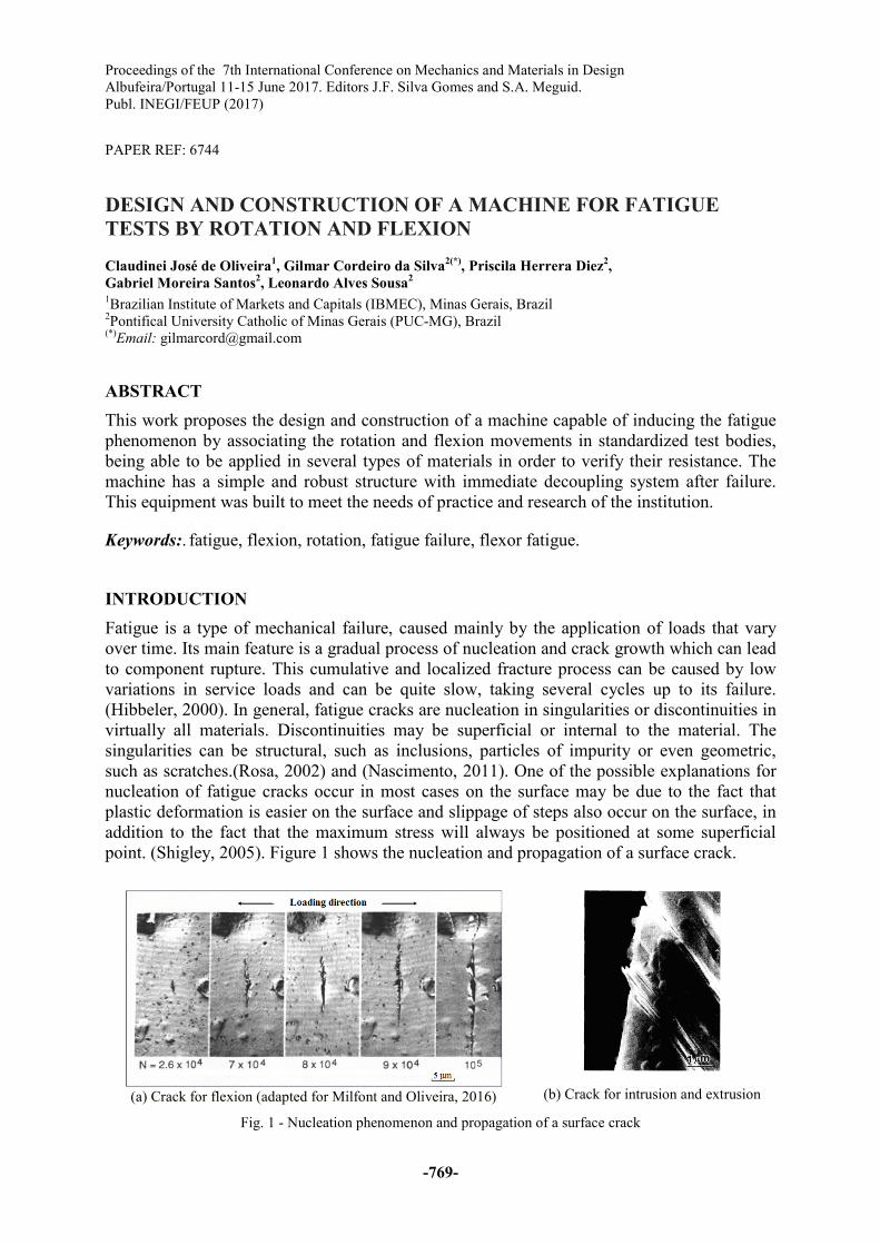
point. (Shigley, 2005). Figure 1 shows the nucleation and propagation of a surface crack.
(a) Crack for flexion (adapted for Milfont and Oliveira, 2016)
(b) Crack for intrusion and extrusion
Fig. 1 - Nucleation phenomenon and propagation of a surface crack

Topic-G: Mechanical Design and Prototyping
-770-
FATIGUE RESISTANCE
And the ability of a material to withstand cyclic loading conditions. However, in the presence
of a measurable plastic deformation, the materials respond differently to the cyclic
deformation than to the cyclic stress. (Torres, 2003)
Cyclic loading will produce cyclic stresses which, in turn, will produce cyclic deformations.
These deformations are elastic in a first moment, however, over time, small plastic
deformations begin to appear starting from existing micro structural defects or geometric
discontinuities of the material. These plastic deformations are permanent deformations and
tend to increase over time and use of the equipment. Therefore, for fatigue failure it is
necessary that three factors be applied simultaneously in the material: a) dynamic demands, b)
tensile stress, c) plastic deformation. (Rosa, 2002)
The characteristics described below, are factors of great impact when the subject is the
resistance to fatigue of materials:
- Surface finish: the better the surface finish the greater its fatigue strength.
- Size of the piece: these are inversely proportional quantities, that is, the larger the
component, the lower its resistance to fatigue.
- Temperature: the metals present an increase in their resistance to fatigue with the
decrease of the temperature.
- Stress concentration: all discontinuities such as notches, holes and grooves modify the
distribution of voltages, causing an increase in localized voltages at certain points.
- Microstructural effects: the fatigue of steels occurs due to their microstructure as well as
the level of impurities present. A tempered and quenched material has better fatigue
characteristics than in its normalized / annealed state.
The limit of resistance to fatigue is determined from the following variables, they are: (Filho,
2010):
- Sf: Fatigue resistance limit for finite life of the test body cycles, where equations 01 and
02 define the boundary conditions.
�� = 10� . � (01)
� = ����. 10
�� (02)
Were, � = − �� . ���
�,�.����� e � = ��� (�,�.���)
��
- Se: Fatigue resistance limit for infinite life of the test body 10� ≤ � ≤ 10",where it is
determined by equation 03..
�� = #$%#%#�%#&%#�%#�% …%�� (03)
Where, Se is the resistance limit of the fatigue element of the machine element, Se' is
the limit of resistance of the test body, ka is the surface finish factor, kb is the size or

Proceedings of the 7th International Conference on Mechanics and Materials in Design
-771-
dimension factor, kc is the reliability factor, kd is the temperature factor, ke is the stress
concentration factor and kf is the factor for other effects.
The behavior of the fatigue can be seen in figure 02 below.
Fig. 2 - Curve S-N (adapted Rosa, 2002)
RESISTANCE TO FATIGUE FOR INFINITE LIFE - Estimative for factors k
The surface of a specimen undergoes a final polishing in the axial direction aiming at a finish
without any notch effects (manufacturing marks). The factor "ka" depends on the quality of
the final workpiece finish and tensile strength of the constituent material, being
mathematically defined by equation 04 (Nascimento, 2011).
#$ = (. ��� (04)
Where, Sut is the minimum tensile strength; And a and b can be determined from table 02
below.
Table 1 - Parameters for the surface modification factor (Shigley, 2005)
Surface Finishing Factor a
Exponent b Sut (Mpa)
Rectified 1.58 -0,085
Machined or cold rolled 4.51 -0,265
Hot rolled 57.7 -0,718
Wrought 272 -0,995
DIMENSION FACTOR (kb)
The calculation of the dimension factor for flexions and torsions is given by equations 05
when (2.79 ≤ d ≤ 51 mm) and 06 when (51 ≤ d ≤ 254 mm)
# = ) &*,"+,
�.����= 1.24/ �.��* (05)

Topic-G: Mechanical Design and Prototyping
-772-
# = 0.859 − 0.000837/ (06)
For values above 254 mm, kb ranges from 0.60 to 0.70 for bending and twisting. If the part is
under axial loads, the diameter does not interfere on the fatigue resistance limit, therefore, we
adopt kb = 1. When the part is not rotating or the cross section is non-circular, the factor value
must be calculated. In these cases the effective diameter is used, which is obtained by
equating the volume of the material subjected to the load and 95% of the maximum load for
the same volume of the test piece. (Shigley, 2005) and (Torres, 2011).
In the case of parts with non-circular sections, the effective diameter is calculated through
equation 07.
/� = 0,808. (�ℎ)� +6 (07)
Where, h is the height, b is the width of the rectangular section.
RELIABILITY FACTOR (kc)
It is the probability of an element or equipment delivering faultless performance over a period
of time, set by the designer, under specified conditions, it is the probability of some type of
failure occurring (Shigley, 2005). The table 2 represents the values of kc.
Table 02 - Reliability Factor (Shigley, 2005)
Reliability Reliability factor (%)
50 1.000
90 0.897
95 0.868
99 0.814
99.9 0.753
99.99 0.702
99.999 0.659
99.9999 0.620
TEMPERATURE FACTOR (kd)
When the design component will operate at a temperature other than the temperature at which
the fatigue tests were performed, a correction in the fatigue strength of the material is required
to suit the working temperature. With this, the temperature factor can be defined according to
equation 08.
#& = 7 1 → 9 ≤ 350°�0.5 → 350°� ≤ 9 ≤ 500°� (08)

Proceedings of the 7th International Conference on Mechanics and Materials in Design
-773-
TENSION CONCENTRATION FACTOR (ke)
The stress concentration is present in structures containing curvatures, notches and other form
of significant perturbation in part geometry. The theoretical concentration factors, "Ke", are
obtained experimentally or can be obtained in proper tables and graphs, as shown in figure 03
below. (Shigley, 2005).
Fig. 3 - Theoretical concentration factor (Shigley, 2005)
This factor, when multiplied by the stress "σ0" (calculated by the mathematical model without
the existence of notch), allows determining the maximum stress that acts on the notch
according to equation 09 (Shigley, 2005).
;<$= = #� . ;� (09)
Depending on the material or its resistance, this geometric or theoretical stress concentration
factor, "kt", undergoes changes, decreasing its intensity as a function of the "q" sensitivity of
the notch. The relation that determines effective or practical factor was defined by Peterson by
equation 10 (Shigley, 2005).
> = ?@ �?AB�
→ #� = 1 C >(#� − 1) (10)
Where, kt is the factor of static tension concentration and kf is the stress concentration factor in
fatigue.
The sensitivity to notch depends on the tensile strength limit and notch radius. The
experimental values use this sensitivity varying from 0 to 1, with the most used values being
between 0.6 and 0.9. (Shigley, 2005).
Calculating the factor "kf", we can use equation 11 below to find the corrective factor ke.

Topic-G: Mechanical Design and Prototyping
-774-
#� = �?@
(11)
VARIABLE FACTOR MODIFICATION FACTOR (kf)
The miscellaneous effects modification factor is reserved for any other type of effect that
occurs on the equipment or machine element that was not mentioned. As an example we have
residual stresses, corrosion, chemical environment and so on.
FATIGUE TESTING
The equipment that performs this type of test is constituted by a system of application of
loads, allowing the change of intensity and direction of the effort. The tests are related to the
type of effort to be applied. Among these tests, the most used are: traction-compression,
torsion and rotational flexion (Shigley, 2005) and (Norton, 2004).
ROTATING FLEXION
This test consists of a test specimen subjected to bending stresses, while it is rotated about an
axis, by a motor system, in a specific and constant rotation. The test starts with a certain
voltage level until the rupture occurs, and the number of cycles and the voltage up to rupture
are recorded. It runs with different specimens of the same material, changing only the applied
voltage. The collected data are represented in diagram S - N. (Silva and Arevalos, 2011) and
(Norton, 2004).
The equipment used to perform the rotary flex fatigue tests consists of a rotary counter, an
electric motor, a load applicator, and supports for the test body. The motor generates the
necessary rotation for the tests. The rotation counter records the number of cycles until the
specimen is ruptured. For bending to occur, devices capable of applying a given load to the
specimen are required, ie by the load applicators. The fixation and support of the test piece are
made by mandrels and forceps (Norton, 2004).
Below, in figures 04 and 05, two models of equipment for the test of fatigue by rotating
flexure are presented. The first has load application at both ends of the test body, while the
second, has load application in only one end of the body.
Fig. 4 - Schematic of a rotary bending fatigue test machine (Udomphol, 2012)
Proceedings of the 7th International Conference on Mechanics and Materials in Design
-775-
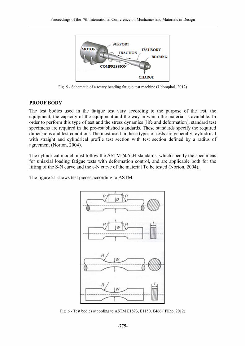
Fig. 5 - Schematic of a rotary bending fatigue test machine (Udomphol, 2012)
PROOF BODY
The test bodies used in the fatigue test vary according to the purpose of the test, the
equipment, the capacity of the equipment and the way in which the material is available. In
order to perform this type of test and the stress dynamics (life and deformation), standard test
specimens are required in the pre-established standards. These standards specify the required
dimensions and test conditions.The most used in these types of tests are generally: cylindrical
with straight and cylindrical profile test section with test section defined by a radius of
agreement (Norton, 2004).
The cylindrical model must follow the ASTM-606-04 standards, which specify the specimens
for uniaxial loading fatigue tests with deformation control, and are applicable both for the
lifting of the S-N curve and the ε-N curve of the material To be tested (Norton, 2004).
The figure 21 shows test pieces according to ASTM.
Fig. 6 - Test bodies according to ASTM E1823, E1150, E466 ( Filho, 2012)

Topic-G: Mechanical Design and Prototyping
-776-
METHODOLOGY
The development of this work was divided in the following stages: initially we carried out a
bibliographical revision of the theory about fatigue tests and then focusing on the type of
rotational flexion. As a second step, we researched the main existing test machines for this
type of test, and then chose type with load bearing at both ends of the rotary axis. Having
chosen the type of machine to be analyzed, a design of the basic mechanical components of
the system was carried out. The proposed kinematic scheme is shown in figure 7.
Fig. 7 - Proposed initial scheme
Through the drawing software Unigraphics NX 9.5 an outline of the project to realize the
budget was realized. The project was finalized in January 2017 and the equipment is
undergoing functional tests. Some improvements may be made, because as the tests involve
cyclic loads, the need to include flexible couplings in order to mitigate vibrations is analyzed.
From the system itself.
.
RESULTS AND CONCLUSIONS
The machine after design and construction, presents the configuration of figure 8 below where
all its components can be seen

Proceedings of the 7th International Conference on Mechanics and Materials in Design
-777-
(a) Structure complete. (b) Description of components.
Fig. 8 - Machine per rotation and bending fatigue.
The stress (S) is generated by the weights that are added during the tests (washer gym), being
able to be up to 25 kg, in which the cycles (N) are measured by a counter coupled to the axis
of rotation, and can generate the points for a curve S-N. The table 03 showing the values for
resolution the equipment.
Table 3 - Weight ratio for equivalent stress
Washer (gym) 1 2 3 4 5
Weight (kg) 5 10 15 20 25
Stress (Mpa) 50 100 150 200 250
ACKNOWLEDGMENTS
The authors are grateful to the technicians of the PUC Minas manufacturing and assembly
laboratory for the help and disposition in the construction and adaptation of the design of this
testing machine.
REFERENCES
[1]-Filho, Flávio de Marco, Notas de Aula, UFRJ, 2010.
[2]-Hibbeler, R.C. Resistência dos Materiais, Terceira Edição, Livros Técnicos e Científicos
Editora, Rio de Janeiro, 2000.
[3]-Marques Silva, Fabrício C., AREVALOS M., Rodrigo, Modernização da Máquina de
Fadiga por Flexão Rotativa do Laboratório de Ensaios de Materiais. Departamento de
Engenharia Mecânica, Universidade de Brasília, 2011.
[4]-Milfont, Gilfran, Oliveira Mauricio. Falhas por Fadiga e notas de aula, 2016, Address:
http://inspecaoequipto.blogspot.com.br/2014/02/falha-por-fadiga.html

Topic-G: Mechanical Design and Prototyping
-778-
[5]-Nascimento, Alexandre Gomes, Avaliação da Resistência à Fadiga de Aços CA6NM,
Universidade de Brasília, 2011.
[6]-Norton, Robert L., Projetos de Máquinas, 2ª ed., Porto Alegre, Bookman, 2004.
[7]-Rosa, Edison da, Análise de resistência mecânica (Mecânica da Fratura e Fadiga), UFSC,
2002.
[8]-Shigley, Joseph E., Mischke, Charles R., Budynas, Richard G. Projeto de Engenharia
Mecânica Translation: João Batista de Aguiar, José Manuel de Aguiar, 7ª ed. Porto Alegre,
Bookman, 2005.
[9]-Torres, Carlos Alberto, Vida em Fadiga de um Ferro Fundido, PUC RJ, 2003.
[10]-Udomphol, T., Mechanical Metallurgy Laboratory - Fatigue Testing, ed. 2012.