design and construction of long-span single-layer dome
TRANSCRIPT
HKIE TRANSACTIONS, 2018VOL. 25, NO. 1, 29–43https://doi.org/10.1080/1023697X.2017.1409663
Design and construction of long-span single-layer dome structures by directanalysis
Y P Liua, S J Panb, Simon W K Leungb and S L Chana
aDepartment of Civil and Environmental Engineering, The Hong Kong Polytechnic University, Hong Kong, People’s Republic of China;bBuilding Construction, China State Construction Engineering (Hong Kong) Limited, Hong Kong, People’s Republic of China
ABSTRACTLong-span roofs are widely used worldwide as they provide large internal spaces withoutobstructions like columns. In designing long-span roofs, the traditional design method facesmany difficulties, such as uncertainty in buckling effective length. The advanced second-orderdirect analysis (SODA) method for design shows and has many advantages for structural safetyand cost saving. In this paper, the SODA considering P- and P-δ effects as well as initial imper-fections is proposed for designing of long-span roofs and the assumption of effective length isno longer required. The application of this concept of SODA to the design of practical structuresappears to benewandunique, especially on the aspects of design at the construction stages. Keyconsiderations for the construction of long-span structures by SODA are first reported. The plan-ning of the lifting procedure, temporary support system (TSS) and off-loading sequences for loadtransfer from a TSS to permanent structure is guided by SODA such that an economic design andsafe construction can be achieved. A constructed long-span single-layer roof structure in Macauis used to demonstrate the validity, practicality, accuracy and reliability of the proposedmethodand is taken as an example of successful joint work for advanced design by academicians andengineers in practice.
ARTICLE HISTORYReceived 13 March 2017Accepted 14 November 2017
KEYWORDSSecond-order direct analysis;construction sequence;long-span structures; domestructures; off-loadinganalysis
1. Introduction
Long-span roof structures are widely constructed instadia, shopping malls, public halls, warehouses, air-port terminals and so on as they provide large inter-nal spaces without obstructing structural supports likecolumns. The commonly used typologies of roof struc-tures include single-layer grids, double- andmulti-layergrids and their combinations. Long-span roofs gener-ally experience large deflections and are sensitive toinitial imperfections and patterned loads, especially forsingle-layer domes. The structural design complexityincludes the fact that roof members cannot be clearlyclassified as beams or columns like their counterpartsin conventional building structures; most steel designcodes are for buildings made of columns and beams.Furthermore, the checking of snap-through or snap-back buckling is beyond the capacity of a traditionallinear design method based on the effective lengthapproach (ELM) due to the complex buckling modeinvolving large deflections.
In Hong Kong and the region such as Singapore,Macau, etc., the second-order direct analysis (SODA)method is quite commonly adopted in design officesfor conventional structural design under static loads[1,2], performance-based seismic design [3], progres-sive collapse analysis, structural fire analysis [4] and
so on. This method is known to reflect the true andultimate structural behaviour of members and framesin the analysis stage more accurately, while the tra-ditional ELM only gives approximate responses withthe need to carry out additional stability checks in thedesign stage after analysis. The stability design checkis not consistent with the analysis and it is based onan engineer’s experience, which becomes unreliablefor complex and uncommon structures with a compli-cated buckling mode. For instance, the value of effec-tive length is not reliable to be determined for shal-low domes susceptible to snap-through buckling. Withconsideration of P- and P-δ effects, initial imperfec-tions and other factors which affect strength, stabilityand stiffness such as joint behaviour, the assumptionof effective length or K-factor required in the designstage can be completely discarded in SODA because theeffects of instability have been automatically consideredrationally and reliably in the equilibrium and stabilitychecks in the analysis stage.
Although the SODA has been well researched [5–9]and its concept has been specified in many moderndesign codes such as EC3 [10], AISC-LRFD [11] andCoPHK [12], previous work mainly focused on theapplication of SODA in design stage for structures aftercompletion, rather than in the construction stage. It
CONTACT S L Chan [email protected]
© 2018 The Hong Kong Institution of Engineers
30
is frequently seen that many long-span roof structurescollapsed during construction, for example, Terminal2E of the Charles de Gaulle airport in Paris (2004)and long-span roof trusses in Italy (2008) [13]. One ofthe causes of collapse is that the professional structuralengineers rarely participate in the process of designduring construction. The design and construction aregenerally carried out separately by different parties,such that the structural instability during constructionis overlooked and leads to a collapse. This issue hasbeen getting more attention in recent years, but manyengineers still mainly adopt the old ELM which, asmentioned above, is unreliable for some complex anduncommon structures.
It should be noted that the geometric configuration,support conditions, joint rigidity and loads of the struc-ture under construction change with the constructionsequence. Due to different structural configurationsincluding absence of permanent supports, the struc-tural behaviour of a structure under construction candiffer greatly from that in design for structures duringpermanent use. To this end, lack of or insufficient tem-porary bracings for long-span structures during con-struction commonly result in collapse incidents. Afterinstallation, the temporary supports should be gradu-ally removed with proper sequences so that the loadscan be safely transferred to the permanent structurewithout unfavourable influences on the permanent roofstructure. This paper shows the importance of fillingthe gap in tasks between design (including analysis),materials manufacturing and delivery, and construc-tion and load transfer from a temporary support system(TSS) to a permanent structure by means of a properdesign and analysis method as a whole for the consider-ation of safety in construction. These issues are hard tobe solved by traditional ELM since the support condi-tions and the system stiffness are kept changing duringthe construction process such that the effective lengthfor a stability check is no longer constant as in a con-ventional static design on the basis of an undeformedcomplete structure. On the contrary, the SODA cancheck the structure at any stage due to the considerationof various failure factors by this method.
In this paper, the SODA considering P- and P-δeffects as well as initial imperfections is proposed forthe design of long-span roofs not only in the final com-pleted stage, but also in the construction stage. The pro-fessional structural engineers are required to be moreinvolved during the construction process for stabilityand safety checks. This paper first presents the key con-siderations for construction of long-span structures bySODA which has not been reported for applicationsin the construction stage before. The planning of sub-division roof panels, the lifting procedure, the TSS andoff-loading sequences for load transfer from a tempo-rary support system to permanent structure and so oncan be effectively modelled and analysed by SODA so
that an economical and safe design for the structuresin construction and completed stages can be developedand achieved.
A practical design of a long-span single-layer domestructure recently constructed in Macau is used todemonstrate the validity and accuracy of the proposedmethod in this paper. As the tapered I-section mem-bers were required in this project for the aestheticconsideration, the curved tapered-three-hinges (TTH)beam-column element [14] allowing formember initialbowing will be reviewed in Section 2. In Section 3, thedesign procedures by SODA for this practical projectwill be introduced. In Sections 4 and 5, the design con-siderations for construction sequences and off-loadingsequences will be discussed, respectively. The SODAis adopted throughout the whole design and construc-tion process achieving a safe and cost-effective designand providing a sustainable solution for design andconstruction of long-span roof structures.
2. Modelling of tapered I-sectionmembers
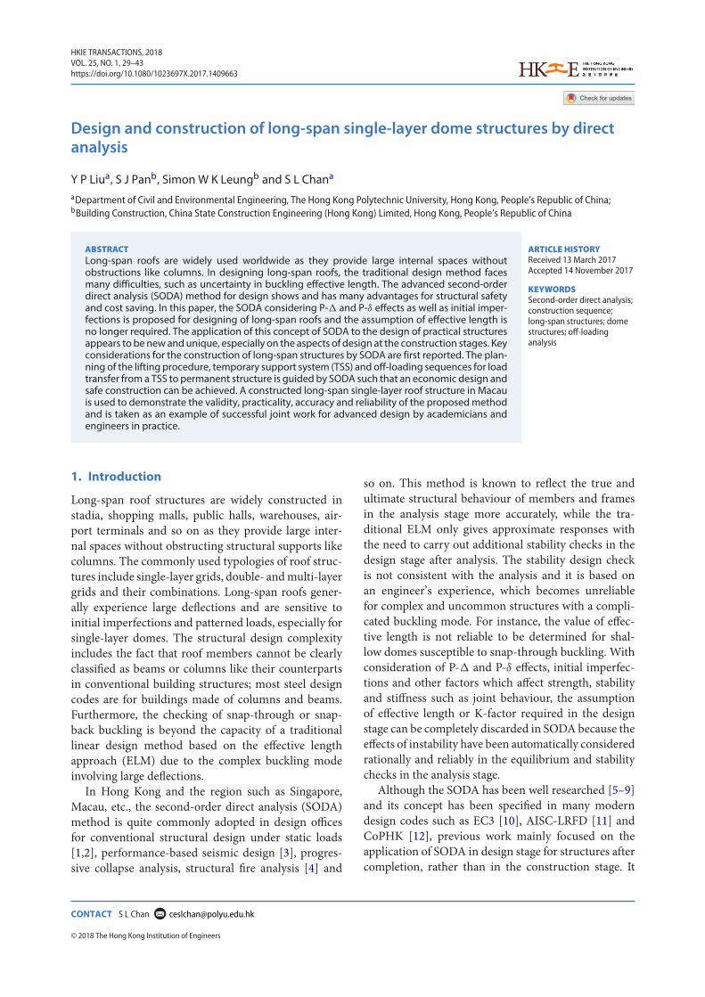
According to modern design codes such as EC3 [10],AISC-LRFD [11] and CoPHK [12], the initial imper-fections in both global frames and local members arethe key factors which should be included in the anal-ysis process of SODA. The global and local imperfec-tions can be considered by adjusting coordinates ofeach node and setting initial bowing of each memberrespectively based on eigen-buckling modes prior toSODA. The former can be easily handled in the anal-ysis procedures while the latter should be supported bya robust and reliable beam-column element allowingfor initial bowing such as the Pointwise-equilibrating-polynomial (PEP) element [15] and the curved stabilityfunction [9]. As non-prismatic member is required inthis project, the curved TTH beam-column element[14] allowing for member initial imperfection will bebriefly introduced as follows for completeness. Thelocalmember basic forces and deformations of the TTHelement can be seen in Figure 1.
(a)
(b)
Figure 1. Localmemberbasic forces anddeformations: (a) localx-y plan; and (b) local x-z plan.
Y P LIU ET AL.
31
The Euler-Bernoulli hypothesis is adopted andwarping and shear deformation is neglected in the TTHelement. The applied loads are conservative and nodal.The total potential energy of the system can beexpressed as the sum of the strain energy U and theexternal work done W as:
= U − W, (1)
U = 12
∫LEAu2dx +
∑ 12
∫LEIn(x)v2ndx
+∑ 1
2
∫LP(v2n + 2v0nvn)dx
+∑∫
θm,n
Sm,ndθ (n = y, z), (2)
W =∑
Fiui, (3)
in which EA is the axial stiffness constant and meanvalue for non-prismatic section taken in this paper;EIn(x) is the flexural stiffness about y- or z- axis andchanged with x along the member for tapered section;θm,n and Sm,n are the hinge rotations and stiffness of theinternal plastic hinge at y- or z- axis; P is axial force;u is the axial displacement function considering bow-ing effects; vn is the transverse displacement functionbased on three-order polynomial; and v0n is the trans-verse displacement function for initial imperfections.More details on the shape functions of u, vn and v0n canbe found in Liu et al. [14].
By the minimum potential energy principle, the firstvariation of the potential energy function yields theequilibrium equations as:
δ = ∂
∂ui+ ∂
∂q∂q∂ui
= 0 and i = 1 to 12. (4)
The secant stiffness between forces and displace-ments can be obtained fromEquation (4). Furthermore,the tangent stiffness matrix can be obtained by the sec-ond variation of the total potential energy functionas:
δ2 = ∂2
∂ui∂ujδuiδuj
=[∂Fi∂uj
+ ∂Fi∂P
∂P∂uj
]δuiδuj and i, j = 1 to 12.
(5)
From Equation (5), the tangent stiffness of the TTHelement can be formulated. In the incremental-iterativenonlinear analysis procedure, tangent stiffness is usedas a predictor for estimating the displacement incre-ment due to small but finite force, while the secantstiffness is used as a corrector of equilibrium. Gener-ally, the Newton–Raphson method is used to find thesolutions of the equilibrium equations. More details of
the secant and tangent stiffnessmatrices of theTTHele-ment should be referred to Liu et al. [14]. The structuraladequacy of every member will be checked using thefollowing section capacity check:
PpyA
+ My + P(y + 0y) + P(δy + δ0y)
Mcy
+ Mz + P(z + 0z) + P(δz + δ0z)
Mcz= ϕ ≤ 1,
(6)
where P is the axial force in member; A is the cross-sectional area; py is the design strength; My, Mz arethe first-order bending moments about the minor andmajor axes; Mcy,Mcz are the moment capacities aboutthe minor and major axes; y,z are the nodal dis-placements due to out-of-plumbness of frame swayinduced by loads; 0y,0z are the nodal displace-ments due to out-of-plumbness of frame imperfections;δy, δz are the member deformations due to loads onthe member; δ0y, δ0z are the member deformations dueto member initial bow; and ϕ is the section capac-ity factor. If ϕ > 1, a member fails in design strengthcheck and if ϕ << 1, the member section is very muchover-designed and the member size can be reduced.
The TTH element and the section capacity checkin Equation (6) have been successfully applied to thedesign of a practical long-span single-layer dome struc-ture which will be used as a case study in this paper. Inthis project, all the steelmembers of the roof are taperedI-sections. For each member, the section depth is var-ied from 300mm to the maximum 800mm while thesection breadth is kept constant.
A simply supported column with initial curvatureof L/400 under pure compression is studied here toverify the validity and accuracy of the TTH element.Due to the existing initial geometrical imperfection, aP-δ moment will be induced at the mid-span of thecolumn. The end moments at two ends can be easilyconsidered by standard finite element procedure. Thus,this simple example can be used to test the elementperformance for practical projects under general load-ing conditions. The height of the column is 6 m. Thethickness of the flanges and the web is 20mm. Thesection breadth along the member length is 300mm.Only the section depth is allowed to vary from 300mmto 800mm. The steel material is S355 with Young’smodulus of 205,000MPa and Poisson’s ratio of 0.3. Thebuckling loads calculated by the SODAwithout consid-eration of material yielding are listed in Table 1. Theresults using 40 stepped elements by the PEP element[15] are also given for verification purposes. As morethan 40 stepped elements have little influence upon theresults, this set of data can be regarded as the standardanswer to this verification example. It can be seen fromTable 1 that the results by one TTH element per mem-ber generally agree well with those by stepped elements.
HKIE TRANSACTIONS
32
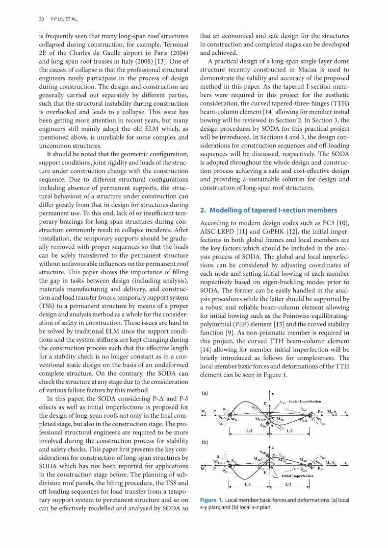
Table 1. Buckling load (Pcr) of a pinned-pinned column using tapered I-section.
D1/D21 ele. (TTH) permemb., kN
40 stepped ele. (PEP)per memb., kN
Pinned-pinned column(tapered I-section)
300/300 4689 (4.67%) 4480
300/400 4717 (4.24%) 4525
300/500 4794 (4.92%) 4569
300/600 4813 (4.56%) 4603
300/700 4836 (4.90%) 4610
300/800 4878 (3.54%) 4711
The differences between the two set results are lessthan 5%. Thus, the precision by one TTH element permember is acceptable for practical application. For con-servative design, the section capacity factor obtainedfrom Equation (6) is limited to 0.95 in practical designas the TTH element exhibits slightly stiffer behaviourthan the PEP element.
3. Design of theMGM Spectacle Roof structureby SODA
The proposed SODA method equipped with the TTHelement [14] has been successfully applied to the designof the “Spectacle Roof” atrium at the MGM resort in
Cotai, Macau, which will be detailed herein as a realcase study.
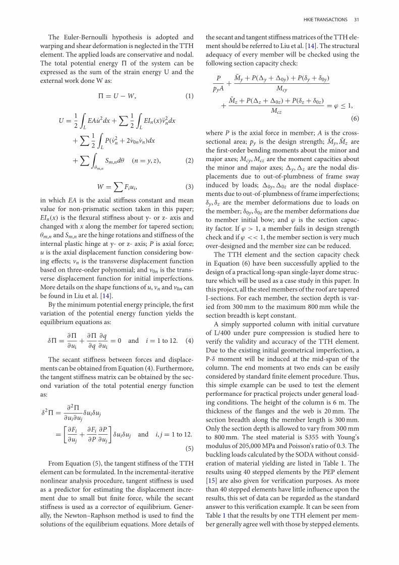
The MGM Spectacle Roof is a single-layer long-span thin shell structure, as shown in Figures 2 and 3.This roof is irregular in geometry with three humps atdifferent heights and takes the form of three vaulted“domes”with “valleys” in between. It covers a large pub-lic space between the hotel towers and associated func-tion and gaming halls. All structural slopes of the roofare less than 30° and the rise-span ratio is not greaterthan 0.2.
In this Section, the major considerations for thedesign of the MGM Spectacle Roof by SODA will beintroduced.
(a)
(b)
Figure 2. Structural dimensions of the MGM Spectacle Roof: (a) plan view; and (b) elevation view.Note: In plan view, N stands for node, M stands for member and B stands for bearing.
Y P LIU ET AL.
33
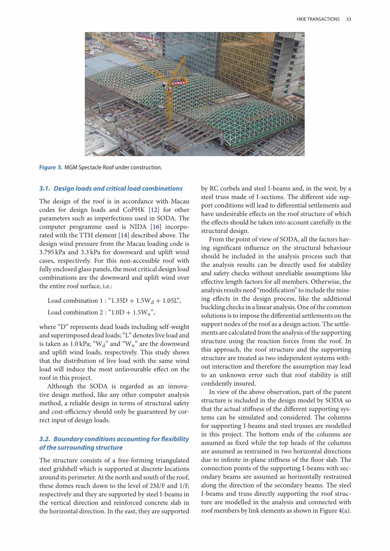
Figure 3. MGM Spectacle Roof under construction.
3.1. Design loads and critical load combinations
The design of the roof is in accordance with Macaucodes for design loads and CoPHK [12] for otherparameters such as imperfections used in SODA. Thecomputer programme used is NIDA [16] incorpo-rated with the TTH element [14] described above. Thedesign wind pressure from the Macau loading code is3.795 kPa and 3.3 kPa for downward and uplift windcases, respectively. For this non-accessible roof withfully enclosed glass panels, the most critical design loadcombinations are the downward and uplift wind overthe entire roof surface, i.e.:
Load combination 1 : “1.35D + 1.5Wd + 1.05L”,
Load combination 2 : “1.0D + 1.5Wu”,
where “D” represents dead loads including self-weightand superimposed dead loads; “L” denotes live load andis taken as 1.0 kPa; “Wd” and “Wu” are the downwardand uplift wind loads, respectively. This study showsthat the distribution of live load with the same windload will induce the most unfavourable effect on theroof in this project.
Although the SODA is regarded as an innova-tive design method, like any other computer analysismethod, a reliable design in terms of structural safetyand cost-efficiency should only be guaranteed by cor-rect input of design loads.
3.2. Boundary conditions accounting for flexibilityof the surrounding structure
The structure consists of a free-forming triangulatedsteel gridshell which is supported at discrete locationsaround its perimeter. At the north and south of the roof,these domes reach down to the level of 2M/F and 1/F,respectively and they are supported by steel I-beams inthe vertical direction and reinforced concrete slab inthe horizontal direction. In the east, they are supported
by RC corbels and steel I-beams and, in the west, by asteel truss made of I-sections. The different side sup-port conditions will lead to differential settlements andhave undesirable effects on the roof structure of whichthe effects should be taken into account carefully in thestructural design.
From the point of view of SODA, all the factors hav-ing significant influence on the structural behaviourshould be included in the analysis process such thatthe analysis results can be directly used for stabilityand safety checks without unreliable assumptions likeeffective length factors for all members. Otherwise, theanalysis results need “modification” to include themiss-ing effects in the design process, like the additionalbuckling checks in a linear analysis.One of the commonsolutions is to impose the differential settlements on thesupport nodes of the roof as a design action. The settle-ments are calculated from the analysis of the supportingstructure using the reaction forces from the roof. Inthis approach, the roof structure and the supportingstructure are treated as two independent systems with-out interaction and therefore the assumption may leadto an unknown error such that roof stability is stillconfidently insured.
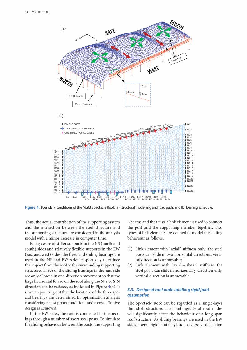
In view of the above observation, part of the parentstructure is included in the design model by SODA sothat the actual stiffness of the different supporting sys-tems can be simulated and considered. The columnsfor supporting I-beams and steel trusses are modelledin this project. The bottom ends of the columns areassumed as fixed while the top heads of the columnsare assumed as restrained in two horizontal directionsdue to infinite in-plane stiffness of the floor slab. Theconnection points of the supporting I-beams with sec-ondary beams are assumed as horizontally restrainedalong the direction of the secondary beams. The steelI-beams and truss directly supporting the roof struc-ture are modelled in the analysis and connected withroof members by link elements as shown in Figure 4(a).
HKIE TRANSACTIONS
34
(a)
(b)
Figure 4. Boundary conditions of the MGM Spectacle Roof: (a) structural modelling and load path; and (b) bearing schedule.
Thus, the actual contribution of the supporting systemand the interaction between the roof structure andthe supporting structure are considered in the analysismodel with a minor increase in computer time.
Being aware of stiffer supports in the NS (north andsouth) sides and relatively flexible supports in the EW(east and west) sides, the fixed and sliding bearings areused in the NS and EW sides, respectively to reducethe impact from the roof to the surrounding supportingstructure. Three of the sliding bearings in the east sideare only allowed in one-directionmovement so that thelarge horizontal forces on the roof along the N-S or S-Ndirection can be resisted, as indicated in Figure 4(b). Itis worth pointing out that the locations of the three spe-cial bearings are determined by optimisation analysisconsidering real support conditions and a cost-effectivedesign is achieved.
In the EW sides, the roof is connected to the bear-ings through a number of short steel posts. To simulatethe sliding behaviour between the posts, the supporting
I-beams and the truss, a link element is used to connectthe post and the supporting member together. Twotypes of link elements are defined to model the slidingbehaviour as follows:
(1) Link element with “axial” stiffness only: the steelposts can slide in two horizontal directions, verti-cal direction is unmovable;
(2) Link element with “axial+ shear” stiffness: thesteel posts can slide in horizontal y-direction only,vertical direction is unmovable.
3.3. Design of roof node fulfilling rigid jointassumption
The Spectacle Roof can be regarded as a single-layerthin shell structure. The joint rigidity of roof nodeswill significantly affect the behaviour of a long-spanroof structure. As sliding bearings are used in the EWsides, a semi-rigid joint may lead to excessive deflection
Y P LIU ET AL.
35
compared with a rigid joint. Hence, a rigid joint ispreferred in this project to control deflections.
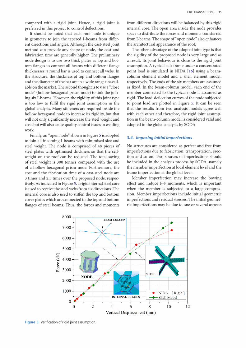
It should be noted that each roof node is uniquein geometry to join the tapered I-beams from differ-ent directions and angles. Although the cast-steel jointmethod can provide any shape of node, the cost andfabrication time are generally higher. The preliminarynode design is to use two thick plates as top and bot-tom flanges to connect all beams with different flangethicknesses; a round bar is used to connect all webs. Inthe structure, the thickness of top and bottom flangesand the diameter of the bar are in a wide range unavail-able on themarket. The second thought is to use a “closenode” (hollow hexagonal prism node) to link the join-ing six I-beams. However, the rigidity of this joint typeis too low to fulfil the rigid joint assumption in theglobal analysis. Many stiffeners are required inside thehollow hexagonal node to increase its rigidity, but thatwill not only significantly increase the steel weight andcost, but will also cause quality control issues inweldingwork.
Finally, an “open node” shown in Figure 5 is adoptedto join all incoming I-beams with minimised size andsteel weight. The node is comprised of 48 pieces ofsteel plates with optimised thickness so that the self-weight on the roof can be reduced. The total savingof steel weight is 300 tonnes compared with the useof a hollow hexagonal prism node. Furthermore, thecost and the fabrication time of a cast-steel node are3 times and 2.5 times over the proposed node, respec-tively. As indicated in Figure 5, a rigid internal steel coreis used to receive the steel webs from six directions. Theinternal core is also used to stiffen the top and bottomcover plates which are connected to the top and bottomflanges of steel beams. Thus, the forces and moments
from different directions will be balanced by this rigidinternal core. The open area inside the node providesspace to distribute the forces and moments transferredfrom I-beams. The shape of “open node” also enhancesthe architectural appearance of the roof.
The other advantage of the adopted joint type is thatthe rigidity of the proposed node is very large and asa result, its joint behaviour is close to the rigid jointassumption. A typical sub-frame under a concentratedpoint load is simulated in NIDA [16] using a beam-column element model and a shell element model,respectively. The ends of the six members are assumedas fixed. In the beam-column model, each end of themember connected to the typical node is assumed asrigid. The load-deflection curves of the node subjectedto point load are plotted in Figure 5. It can be seenthat the results from two analysis models agree wellwith each other and therefore, the rigid joint assump-tion in the beam-columnmodel is considered valid andadopted in the global analysis by SODA.
3.4. Imposing initial imperfections
No structures are considered as perfect and free fromimperfections due to fabrication, transportation, erec-tion and so on. Two sources of imperfections shouldbe included in the analysis process by SODA, namelythe member imperfection at local element level and theframe imperfection at the global level.
Member imperfection may increase the bowingeffect and induce P-δ moments, which is importantwhen the member is subjected to a large compres-sion. Member imperfections include initial geometricimperfections and residual stresses. The initial geomet-ric imperfections may be due to one or several aspects
Figure 5. Verification of rigid joint assumption.
HKIE TRANSACTIONS
36
such as cambering, sweeping, twist, out of straight-ness and cross-section distortion. The residual stressescan be due to the manufacturing and fabrication pro-cesses. In EC3 [10] and CoPHK [12], these two kindsof imperfections are simply combined into an equiv-alent geometric imperfection while AISC-LRFD [11]adopts 0.1% member length as geometric imperfectionand explicitly considers residual stress by the modi-fiedmodulus approach [8]. In this paper, the equivalentinitial bowing imperfections following CoPHK [12] isadopted for the tapered I-beams. The beam-columnelement TTH described in the previous section is usedto model the tapered I-beams.
The frame imperfections are mainly caused by theout-of-plumbness of frame and column in the erectionprocess and during the construction stage. This type ofimperfectionmay increase the sway effect and induce P- moments, especially when the structure is subjectedto large vertical loads.
For regular building structure, the notional horizon-tal force method can be used to consider the globalimperfection. An alternative and more reliable methodfor the complex structure is to use the elastic bucklingmode as the imperfection mode with amplitude equalto height or span/300. In this project, the amplitude ofspan/300 is used. The global imperfection is imposedby modifying the node coordinates while the mem-ber imperfections can be enforced by setting the initialbowing to the same direction as the buckling modeshape.
4. Design considerations on constructionsequence
The design mentioned above is the first step bringinga structure to be plotted in the 2D AutoCAD draw-ings or the 3D BIM model. Apart from the refineddesign by SODA, the final structural configuration alsodepends on the careful consideration of constructionsequences of other related matters, like the availabilityof machinery equipment. For long-span structures, it iscommon to divide them into modules in shop for easytransportation, site assembling and up-lifting with con-sideration of the capacity of crane and TSSs. Structuralengineers play an important role in the checking of thestability of TSS and assembly units during construction.
The size of an assembly unit not only affects safety, butalso the cost of the TSS.
4.1. Delivery and lifting plan
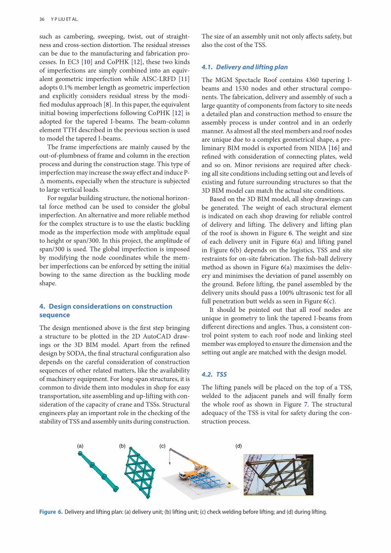
The MGM Spectacle Roof contains 4360 tapering I-beams and 1530 nodes and other structural compo-nents. The fabrication, delivery and assembly of such alarge quantity of components from factory to site needsa detailed plan and construction method to ensure theassembly process is under control and in an orderlymanner. As almost all the steelmembers and roof nodesare unique due to a complex geometrical shape, a pre-liminary BIM model is exported from NIDA [16] andrefined with consideration of connecting plates, weldand so on. Minor revisions are required after check-ing all site conditions including setting out and levels ofexisting and future surrounding structures so that the3D BIM model can match the actual site conditions.
Based on the 3D BIM model, all shop drawings canbe generated. The weight of each structural elementis indicated on each shop drawing for reliable controlof delivery and lifting. The delivery and lifting planof the roof is shown in Figure 6. The weight and sizeof each delivery unit in Figure 6(a) and lifting panelin Figure 6(b) depends on the logistics, TSS and siterestraints for on-site fabrication. The fish-ball deliverymethod as shown in Figure 6(a) maximises the deliv-ery and minimises the deviation of panel assembly onthe ground. Before lifting, the panel assembled by thedelivery units should pass a 100% ultrasonic test for allfull penetration butt welds as seen in Figure 6(c).
It should be pointed out that all roof nodes areunique in geometry to link the tapered I-beams fromdifferent directions and angles. Thus, a consistent con-trol point system to each roof node and linking steelmemberwas employed to ensure the dimension and thesetting out angle are matched with the design model.
4.2. TSS
The lifting panels will be placed on the top of a TSS,welded to the adjacent panels and will finally formthe whole roof as shown in Figure 7. The structuraladequacy of the TSS is vital for safety during the con-struction process.
(a) (b) (c) (d)
Figure 6. Delivery and lifting plan: (a) delivery unit; (b) lifting unit; (c) check welding before lifting; and (d) during lifting.
Y P LIU ET AL.
37
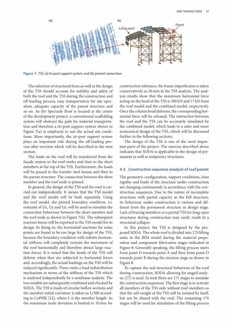
(a) (b)
Figure 7. TSS: (a) tri-post support system; and (b) pinned connection.
The selection of structural form as well as the designof the TSS should account for stability and safety ofboth the roof and the TSS during the construction andoff-loading process, easy transportation for site oper-ation, adequate capacity of the parent structure andso on. As the Spectacle Roof is located at the centreof the development project, a conventional scaffoldingsystem will obstruct the path for material transporta-tion and therefore a tri-post support system shown inFigure 7(a) is employed to suit the actual site condi-tions. More importantly, the tri-post support systemplays an important role during the off-loading pro-cess after erection which will be described in the nextsection.
The loads on the roof will be transferred from thefaçade system to the roof nodes and then to the shortmembers at the top of the TSS. Furthermore, the loadswill be passed to the transfer steel beams and then tothe parent structure. The connection between the shortmember and the roof node is pinned.
In general, the design of the TSS and the roof is car-ried out independently. It means that the TSS modeland the roof model will be built separately. Usingthe roof model, the pinned boundary condition, i.e.restraint of Ux, Uy and Uz, will be used to simulate theconnection behaviour between the short member andthe roof node as shown in Figure 7(b). The subsequentreaction forces will be exported to the TSSmodel for itsdesign. In doing so, the horizontal reactions for somepoints are found to be too large for design of the TSS,because the boundary condition with infinite horizon-tal stiffness will completely restrain the movement ofthe roof horizontally and therefore attract large reac-tion forces. It is noted that the heads of the TSS willdeform when they are subjected to horizontal forcesand, accordingly, the actual loadings on the TSS will bereduced significantly. There exists a load redistributionmechanism in terms of the stiffness of the TSS whichis analysed independently by a nonlinear analysis. Thetwomodels are subsequently combined and checked bySODA. The TSS is made of circular hollow sections andthe member initial curvature is taken as L/500 accord-ing to CoPHK [12], where L is the member length. Asthe maximum node deviation is limited to 10mm for
construction tolerance, the frame imperfection is takenconservatively as 20mm in the TSS analysis. The anal-ysis results show that the maximum horizontal forceacting on the head of the TSS is 309 kN and 17 kN fromthe roof model and the combined model, respectively.Once the columnheaddeforms, the corresponding hor-izontal force will be released. The interaction betweenthe roof and the TSS can be accurately simulated bythe combined model, which leads to a safer and moreeconomical design of the TSS, which will be discussedfurther in the following sections.
The design of the TSS is one of the most impor-tant parts of the project. The exercise described aboveindicates that SODA is applicable to the design of per-manent as well as temporary structures.
4.3. Construction sequence analysis of roof panels
The geometric configuration, support conditions, jointrigidity and loads of the structure under constructionare changing continuously in accordance with the con-struction sequences. Due to the nature of incompletestructures with partial capacity as the full structure,its behaviour under construction is various and dif-ferent from the permanent structure in design stage.Lack of bracing members or a partial TSS for long-spanstructures during construction may easily result in astructural collapse.
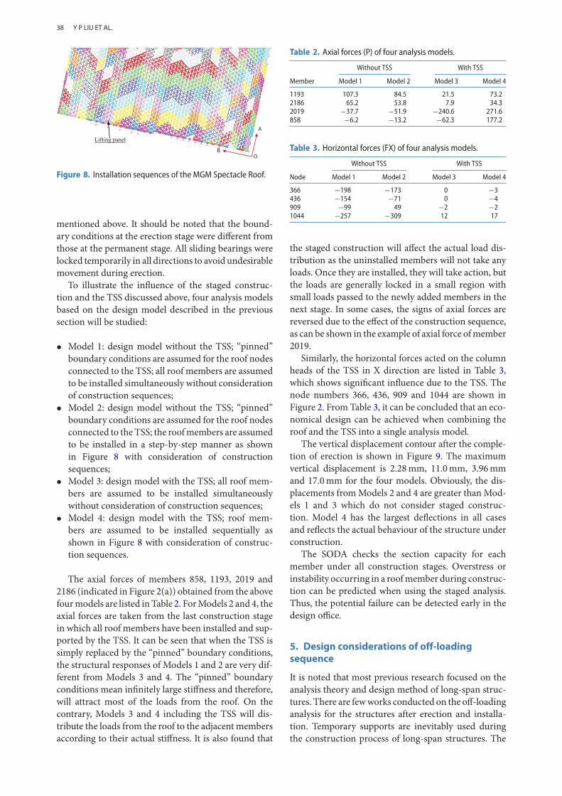
In this project, the TSS is designed by the pro-posed SODA. The whole roof is divided into 170 liftingunits in the BIM model during the material prepa-ration and component fabrication stages indicated inFigure 8. Generally speaking, the lifting process startsfrom point O towards point A and then from point Otowards point B during the erection stage as shown inFigure 8.
To capture the real structural behaviour of the roofduring construction, SODA allowing for staged analy-sis [17] is used. In total there are 171 stages to simulatethe construction sequences. The first stage is to activateall members of the TSS only without roof members sothat the self-weight of the TSS will be resisted by itself,but not be shared with the roof. The remaining 170stages will be used for simulation of the lifting process
HKIE TRANSACTIONS
38
Figure 8. Installation sequences of the MGM Spectacle Roof.
mentioned above. It should be noted that the bound-ary conditions at the erection stage were different fromthose at the permanent stage. All sliding bearings werelocked temporarily in all directions to avoid undesirablemovement during erection.
To illustrate the influence of the staged construc-tion and the TSS discussed above, four analysis modelsbased on the design model described in the previoussection will be studied:
• Model 1: design model without the TSS; “pinned”boundary conditions are assumed for the roof nodesconnected to the TSS; all roof members are assumedto be installed simultaneously without considerationof construction sequences;
• Model 2: design model without the TSS; “pinned”boundary conditions are assumed for the roof nodesconnected to the TSS; the roofmembers are assumedto be installed in a step-by-step manner as shownin Figure 8 with consideration of constructionsequences;
• Model 3: design model with the TSS; all roof mem-bers are assumed to be installed simultaneouslywithout consideration of construction sequences;
• Model 4: design model with the TSS; roof mem-bers are assumed to be installed sequentially asshown in Figure 8 with consideration of construc-tion sequences.
The axial forces of members 858, 1193, 2019 and2186 (indicated in Figure 2(a)) obtained from the abovefourmodels are listed inTable 2. ForModels 2 and 4, theaxial forces are taken from the last construction stagein which all roof members have been installed and sup-ported by the TSS. It can be seen that when the TSS issimply replaced by the “pinned” boundary conditions,the structural responses of Models 1 and 2 are very dif-ferent from Models 3 and 4. The “pinned” boundaryconditions mean infinitely large stiffness and therefore,will attract most of the loads from the roof. On thecontrary, Models 3 and 4 including the TSS will dis-tribute the loads from the roof to the adjacent membersaccording to their actual stiffness. It is also found that
Table 2. Axial forces (P) of four analysis models.
Without TSS With TSS
Member Model 1 Model 2 Model 3 Model 4
1193 107.3 84.5 21.5 73.22186 65.2 53.8 7.9 34.32019 −37.7 −51.9 −240.6 271.6858 −6.2 −13.2 −62.3 177.2
Table 3. Horizontal forces (FX) of four analysis models.
Without TSS With TSS
Node Model 1 Model 2 Model 3 Model 4
366 −198 −173 0 −3436 −154 −71 0 −4909 −99 49 −2 −21044 −257 −309 12 17
the staged construction will affect the actual load dis-tribution as the uninstalled members will not take anyloads. Once they are installed, they will take action, butthe loads are generally locked in a small region withsmall loads passed to the newly added members in thenext stage. In some cases, the signs of axial forces arereversed due to the effect of the construction sequence,as can be shown in the example of axial force ofmember2019.
Similarly, the horizontal forces acted on the columnheads of the TSS in X direction are listed in Table 3,which shows significant influence due to the TSS. Thenode numbers 366, 436, 909 and 1044 are shown inFigure 2. From Table 3, it can be concluded that an eco-nomical design can be achieved when combining theroof and the TSS into a single analysis model.
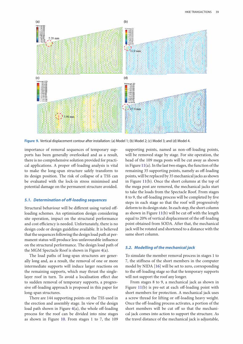
The vertical displacement contour after the comple-tion of erection is shown in Figure 9. The maximumvertical displacement is 2.28mm, 11.0mm, 3.96mmand 17.0mm for the four models. Obviously, the dis-placements fromModels 2 and 4 are greater thanMod-els 1 and 3 which do not consider staged construc-tion. Model 4 has the largest deflections in all casesand reflects the actual behaviour of the structure underconstruction.
The SODA checks the section capacity for eachmember under all construction stages. Overstress orinstability occurring in a roofmember during construc-tion can be predicted when using the staged analysis.Thus, the potential failure can be detected early in thedesign office.
5. Design considerations of off-loadingsequence
It is noted that most previous research focused on theanalysis theory and design method of long-span struc-tures. There are fewworks conducted on the off-loadinganalysis for the structures after erection and installa-tion. Temporary supports are inevitably used duringthe construction process of long-span structures. The
Y P LIU ET AL.
39
(a) (b)
(c) (d)
Figure 9. Vertical displacement contour after installation: (a) Model 1; (b) Model 2; (c) Model 3; and (d) Model 4.
importance of removal sequences of temporary sup-ports has been generally overlooked and as a result,there is no comprehensive solution provided for practi-cal applications. A proper off-loading analysis is vitalto make the long-span structure safely transform toits design position. The risk of collapse of a TSS canbe evaluated with the lock-in stress minimised andpotential damage on the permanent structure avoided.
5.1. Determination of off-loading sequences
Structural behaviour will be different using varied off-loading schemes. An optimisation design consideringsite operation, impact on the structural performanceand cost efficiency is needed. Unfortunately, there is nodesign code or design guideline available. It is believedthat the sequences following the design load path at per-manent status will produce less unfavourable influenceon the structural performance. The design load path ofthe MGM Spectacle Roof is shown in Figure 4(a).
The load paths of long-span structures are gener-ally long and, as a result, the removal of one or moreintermediate supports will induce larger reactions onthe remaining supports, which may thrust the single-layer roof in turn. To avoid a localisation effect dueto sudden removal of temporary supports, a progres-sive off-loading approach is proposed in this paper forlong-span structures.
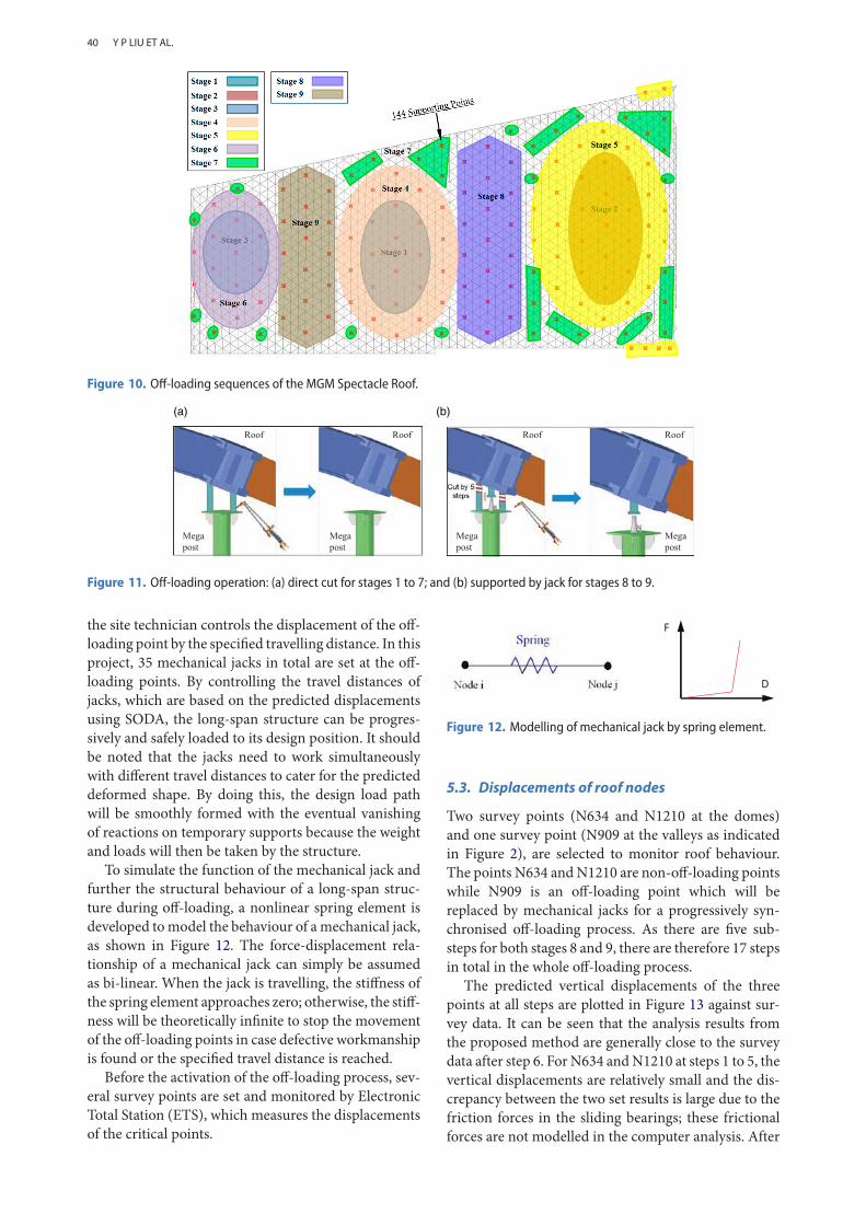
There are 144 supporting points on the TSS used inthe erection and assembly stage. In view of the designload path shown in Figure 4(a), the whole off-loadingprocess for the roof can be divided into nine stagesas shown in Figure 10. From stages 1 to 7, the 109
supporting points, named as non-off-loading points,will be removed stage by stage. For site operation, thehead of the 109 mega posts will be cut away as shownin Figure 11(a). In the last two stages, the function of theremaining 35 supporting points, namely as off-loadingpoints, will be replaced by 35mechanical jacks as shownin Figure 11(b). Once the short columns at the top ofthe mega post are removed, the mechanical jacks startto take the loads from the Spectacle Roof. From stages8 to 9, the off-loading process will be completed by fivesteps in each stage so that the roof will progressivelydeform to its design state. In each step, the short columnas shown in Figure 11(b) will be cut off with the lengthequal to 20% of vertical displacement of the off-loadingpoint obtained from SODA. After that, the mechanicaljack will be rotated and shortened to a distance with thesame short column.
5.2. Modelling of themechanical jack
To simulate the member removal process in stages 1 to7, the stiffness of the short members in the computermodel by NIDA [16] will be set to zero, correspondingto the off-loading stage so that the temporary supportswill not support the roof any longer.
From stages 8 to 9, a mechanical jack as shown inFigure 11(b) is pre-set at each off-loading point withshort members for protection. A mechanical jack usesa screw thread for lifting or off-loading heavy weight.Once the off-loading process activates, a portion of theshort members will be cut off so that the mechani-cal jack comes into action to support the structure. Asthe travel distance of the mechanical jack is adjustable,
HKIE TRANSACTIONS
40
Figure 10. Off-loading sequences of the MGM Spectacle Roof.
(a) (b)
Figure 11. Off-loading operation: (a) direct cut for stages 1 to 7; and (b) supported by jack for stages 8 to 9.
the site technician controls the displacement of the off-loading point by the specified travelling distance. In thisproject, 35 mechanical jacks in total are set at the off-loading points. By controlling the travel distances ofjacks, which are based on the predicted displacementsusing SODA, the long-span structure can be progres-sively and safely loaded to its design position. It shouldbe noted that the jacks need to work simultaneouslywith different travel distances to cater for the predicteddeformed shape. By doing this, the design load pathwill be smoothly formed with the eventual vanishingof reactions on temporary supports because the weightand loads will then be taken by the structure.
To simulate the function of the mechanical jack andfurther the structural behaviour of a long-span struc-ture during off-loading, a nonlinear spring element isdeveloped tomodel the behaviour of amechanical jack,as shown in Figure 12. The force-displacement rela-tionship of a mechanical jack can simply be assumedas bi-linear. When the jack is travelling, the stiffness ofthe spring element approaches zero; otherwise, the stiff-ness will be theoretically infinite to stop the movementof the off-loading points in case defective workmanshipis found or the specified travel distance is reached.
Before the activation of the off-loading process, sev-eral survey points are set and monitored by ElectronicTotal Station (ETS), which measures the displacementsof the critical points.
Figure 12. Modelling of mechanical jack by spring element.
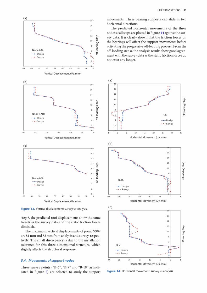
5.3. Displacements of roof nodes
Two survey points (N634 and N1210 at the domes)and one survey point (N909 at the valleys as indicatedin Figure 2), are selected to monitor roof behaviour.The points N634 andN1210 are non-off-loading pointswhile N909 is an off-loading point which will bereplaced by mechanical jacks for a progressively syn-chronised off-loading process. As there are five sub-steps for both stages 8 and 9, there are therefore 17 stepsin total in the whole off-loading process.
The predicted vertical displacements of the threepoints at all steps are plotted in Figure 13 against sur-vey data. It can be seen that the analysis results fromthe proposed method are generally close to the surveydata after step 6. ForN634 andN1210 at steps 1 to 5, thevertical displacements are relatively small and the dis-crepancy between the two set results is large due to thefriction forces in the sliding bearings; these frictionalforces are not modelled in the computer analysis. After
Y P LIU ET AL.
41
Figure 13. Vertical displacement: survey vs analysis.
step 6, the predicted roof displacements show the sametrends as the survey data and the static friction forcesdiminish.
The maximum vertical displacements of point N909are 81mmand 83mm fromanalysis and survey, respec-tively. The small discrepancy is due to the installationtolerance for this three-dimensional structure, whichslightly affects the structural response.
5.4. Movements of support nodes
Three survey points (“B-6”, “B-9” and “B-18” as indi-cated in Figure 2) are selected to study the support
movements. These bearing supports can slide in twohorizontal directions.
The predicted horizontal movements of the threenodes at all steps are plotted in Figure 14 against the sur-vey data. It is clearly shown that the friction forces onthe bearings will affect the support movements beforeactivating the progressive off-loading process. From theoff-loading step 8, the analysis results show good agree-ment with the survey data as the static friction forces donot exist any longer.
Figure 14. Horizontal movement: survey vs analysis.
HKIE TRANSACTIONS
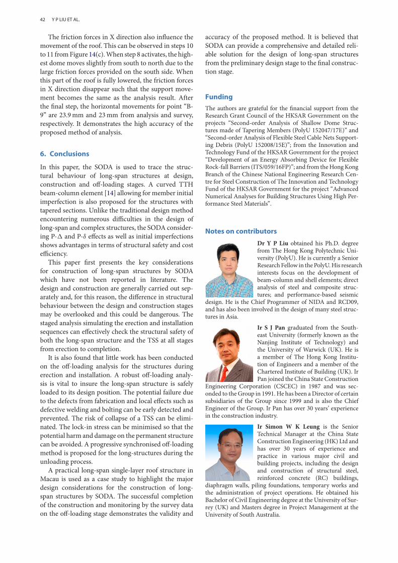
42
The friction forces in X direction also influence themovement of the roof. This can be observed in steps 10to 11 fromFigure 14(c).When step 8 activates, the high-est dome moves slightly from south to north due to thelarge friction forces provided on the south side. Whenthis part of the roof is fully lowered, the friction forcesin X direction disappear such that the support move-ment becomes the same as the analysis result. Afterthe final step, the horizontal movements for point “B-9” are 23.9mm and 23mm from analysis and survey,respectively. It demonstrates the high accuracy of theproposed method of analysis.
6. Conclusions
In this paper, the SODA is used to trace the struc-tural behaviour of long-span structures at design,construction and off-loading stages. A curved TTHbeam-column element [14] allowing formember initialimperfection is also proposed for the structures withtapered sections. Unlike the traditional design methodencountering numerous difficulties in the design oflong-span and complex structures, the SODA consider-ing P- and P-δ effects as well as initial imperfectionsshows advantages in terms of structural safety and costefficiency.
This paper first presents the key considerationsfor construction of long-span structures by SODAwhich have not been reported in literature. Thedesign and construction are generally carried out sep-arately and, for this reason, the difference in structuralbehaviour between the design and construction stagesmay be overlooked and this could be dangerous. Thestaged analysis simulating the erection and installationsequences can effectively check the structural safety ofboth the long-span structure and the TSS at all stagesfrom erection to completion.
It is also found that little work has been conductedon the off-loading analysis for the structures duringerection and installation. A robust off-loading analy-sis is vital to insure the long-span structure is safelyloaded to its design position. The potential failure dueto the defects from fabrication and local effects such asdefective welding and bolting can be early detected andprevented. The risk of collapse of a TSS can be elimi-nated. The lock-in stress can be minimised so that thepotential harm and damage on the permanent structurecan be avoided. A progressive synchronised off-loadingmethod is proposed for the long-structures during theunloading process.
A practical long-span single-layer roof structure inMacau is used as a case study to highlight the majordesign considerations for the construction of long-span structures by SODA. The successful completionof the construction and monitoring by the survey dataon the off-loading stage demonstrates the validity and
accuracy of the proposed method. It is believed thatSODA can provide a comprehensive and detailed reli-able solution for the design of long-span structuresfrom the preliminary design stage to the final construc-tion stage.
Funding
The authors are grateful for the financial support from theResearch Grant Council of the HKSAR Government on theprojects “Second-order Analysis of Shallow Dome Struc-tures made of Tapering Members (PolyU 152047/17E)” and“Second-order Analysis of Flexible Steel Cable Nets Support-ing Debris (PolyU 152008/15E)”; from the Innovation andTechnology Fund of the HKSAR Government for the project“Development of an Energy Absorbing Device for FlexibleRock-fall Barriers (ITS/059/16FP)”; and from theHongKongBranch of the Chinese National Engineering Research Cen-tre for Steel Construction of The Innovation and TechnologyFund of the HKSAR Government for the project “AdvancedNumerical Analyses for Building Structures Using High Per-formance Steel Materials”.
Notes on contributors
Dr Y P Liu obtained his Ph.D. degreefrom The Hong Kong Polytechnic Uni-versity (PolyU). He is currently a SeniorResearch Fellow in the PolyU.His researchinterests focus on the development ofbeam-column and shell elements; directanalysis of steel and composite struc-tures; and performance-based seismic
design. He is the Chief Programmer of NIDA and RCD09,and has also been involved in the design of many steel struc-tures in Asia.
Ir S J Pan graduated from the South-east University (formerly known as theNanjing Institute of Technology) andthe University of Warwick (UK). He isa member of The Hong Kong Institu-tion of Engineers and a member of theChartered Institute of Building (UK). IrPan joined the China State Construction
Engineering Corporation (CSCEC) in 1987 and was sec-onded to the Group in 1991. He has been aDirector of certainsubsidiaries of the Group since 1999 and is also the ChiefEngineer of the Group. Ir Pan has over 30 years’ experiencein the construction industry.
Ir Simon W K Leung is the SeniorTechnical Manager at the China StateConstruction Engineering (HK) Ltd andhas over 30 years of experience andpractice in various major civil andbuilding projects, including the designand construction of structural steel,reinforced concrete (RC) buildings,
diaphragm walls, piling foundations, temporary works andthe administration of project operations. He obtained hisBachelor of Civil Engineering degree at the University of Sur-rey (UK) and Masters degree in Project Management at theUniversity of South Australia.
Y P LIU ET AL.
43
Ir Prof S L Chan is the Chair Professorin Computational Structural Engineer-ing in the Department of Civil and Envi-ronmental Engineering at the PolyU.Hisresearch interests cover nonlinear struc-tural analysis with the applications fordesign, steel, composite and glass struc-tures, buckling and stability.
References
[1] Liu YP, Chan SL, Zhou ZH, et al. Second-order anal-ysis and design of wall-framed structures allowing forimperfections. Adv Struct Eng. 2010;13(3):513–524.doi:10.1260/1369-4332.13.3.513
[2] Chan SL, Liu YP, Zhou ZH. Limitation of effec-tive length method and codified second-order analysisand design. Steel Compos Struct. 2005;5(2-3):181–192.doi:10.12989/scs.2005.5.2_3.181
[3] Liu SW, Liu YP, Chan SL. Pushover analysis by oneelement per member for performance-based seismicdesign. Int J Struct Stab Dyn. 2010;10(1):111–126.doi:10.1142/S0219455410003385
[4] Liu YP, Yuen SW, Chan SL. Nonlinear analysis and test-ing of structures under fire. The HKIE - Fire Division6th Annual Symposium, Hong Kong, 8 Apr 2014.
[5] Liu SW, Liu YP, Chan SL. Direct analysis by anarbitrarily-located-plastic-hinge element — part 1: pla-nar analysis. J Constr Steel Res. 2014;103:303–315.doi:10.1016/j.jcsr.2014.07.009
[6] Liu SW, Liu YP, Chan SL. Direct analysis by anarbitrarily-located-plastic-hinge element — part 2: spa-tial analysis. J Constr Steel Res. 2014;103:316–326.doi:10.1016/j.jcsr.2014.07.010
[7] Surovek AE, White DW, Leon RT. Direct analysis fordesign evaluation of partially restrained steel framing
systems. J Struct Eng-Asce. 2005;131(9):1376–1389.doi:10.1061/(ASCE)0733-9445(2005)131:9(1376)
[8] Ziemian RD, McGuire W. Modified tangent modulusapproach, a contribution to plastic hinge analysis. JStruct Eng-Asce. 2002;128(10):1301–1307. doi:10.1061/(ASCE)0733-9445(2002)128:10(1301)
[9] Chan SL, Gu JX. Exact tangent stiffness for imperfectbeam-columnmembers. J Struct Eng-Asce. 2000;126(9):1094–1102. doi:10.1061/(ASCE)0733-9445(2000)126:9(1094)
[10] (CEN), E.C.f.S. Eurocode 3: design of steel structures -part 1-1: general rules and rules for buildings. 2005.
[11] AISC-LRFD. Specification for structural steel buildings.AISC, Inc., One EastWacker Driver, Suite 700, Chicago,Illinois 60601-1802, 2010.
[12] CoPHK. Code of practice for the structural use of steel2011. Hong Kong, China: Buildings Department, theHKSAR Government; 2011.
[13] Augenti N, Parisi F. Buckling analysis of a long-spanroof structure collapsed during construction. J PerformConstr Fac. 2013;27(1):77–88. doi:10.1061/(ASCE)CF.1943-5509.0000302
[14] Liu SW, Bai R, Chan SL, et al. Second-order directanalysis of domelike structures consisting of taperedmembers with I-sections. J Struct Eng. 2016;142(5).
[15] Chan SL, Zhou ZH. Second-order elastic analysis offrames using single imperfect element per member.J Struct Eng-Asce. 1995;121(6):939–945. doi:10.1061/(ASCE)0733-9445(1995)121:6(939)
[16] NIDA. User’s manual, nonlinear integrated designand analysis. NIDA 9.0 HTML Online Documenta-tion., 2015. Available from: http://www.nidacse.com
[17] Liu YP, Chan SL. Second-order and advanced anal-ysis of structures allowing for load and construc-tion sequences. Adv Struct Eng. 2011;14(4):635–646.doi:10.1260/1369-4332.14.4.635
HKIE TRANSACTIONS