design and construction of multitier shoring towers · journal of engineering sciences, assiut...
TRANSCRIPT
Journal of Engineering Sciences, Assiut University, Vol. 40, No.3. pp. 689 -700 May 2012
689
DESIGN AND CONSTRUCTION OF MULTITIER SHORING TOWERS
K.M.Shawki*; M.A.Emam**; El-B. Osman*** * Associate prof., College of Eng. and Technology, AASTMT,
Alexandria, Egypt. **
Professor, College of Eng. and Technology, AASTMT, Cairo, Egypt ***
M.Sc. College of Eng. and Technology, AASTMT, Alexandria, Egypt
(Received January 29, 2012 Accepted February 15, 2012)
The construction of heavy and high concrete slabs is considered as a great
problem in projects because they need very efficient formwork systems. The
multi-tiers shoring towers (as vertical supporting members ) appears as the
common solution for this problem in addition to plywood sheathing, steel,
wood ,aluminum as joists, stringers as secondary and main beams . The
multi-tiers shoring towers are made of painted steel, galvanized steel or
aluminum, they are modular, can be used a large number of time, much
faster to erect and have high loading capacity. According to increase in
demand for this type, the reason to study them is extremely needed. This
paper determines the minimum weight of slab formwork using this system.
The genetic algorithm is used as an optimization technique. An example is
provided to illustrate the design procedure. The design procedure is
shown through a computer model called OSAF.
KEYWORDS: Formwork, optimization, multitier
1. INTRODUCTION
Formwork for heavy and high-clearance concrete construction is commonly based on
multitier shoring towers, also termed load towers or support towers, which essentially
are “frame based” systems, to distinguish from “tube and coupler” systems. Thus, shoring towers of various heights are an inseparable part of the construction scene in
commercial, residential, industrial, public, and civil engineering projects all over.
Demand for their use has grown even more since erection and dismantling convenience
renders such towers also a likely shoring solution for low-clearance construction,
where single props have traditionally been used. Furthermore, towers often serve as
temporary supports in precast concrete construction, and even as access scaffolds.
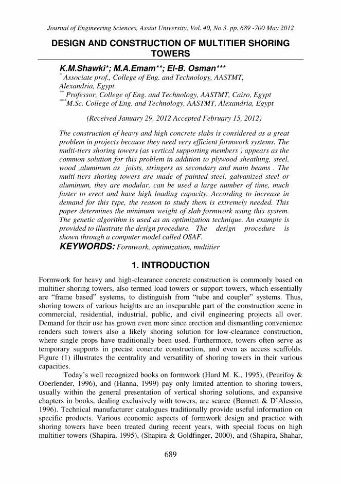
Figure (1) illustrates the centrality and versatility of shoring towers in their various
capacities.
Today’s well recognized books on formwork (Hurd M. K., 1995), (Peurifoy &
Oberlender, 1996), and (Hanna, 1999) pay only limited attention to shoring towers,
usually within the general presentation of vertical shoring solutions, and expansive
chapters in books, dealing exclusively with towers, are scarce (Bennett & D’Alessio, 1996). Technical manufacturer catalogues traditionally provide useful information on
specific products. Various economic aspects of formwork design and practice with
shoring towers have been treated during recent years, with special focus on high
multitier towers (Shapira, 1995), (Shapira & Goldfinger, 2000), and (Shapira, Shahar,
K.M.Shawki; M.A.Emam; El-B. Osman
690
& Raz, 2001), (Shapira, 2004). Those studies on high towers, were motivated mainly
by the high cost of tower-based formwork relative to the overall construction cost of
the supported concrete element, which is significantly higher than the common
estimates of 40–60%, that are in themselves quite high (Hanna, 1999).
Figure (1): Example tower configurations. (Shapira & Raz, 2005)
Shoring towers are made up of hand carried elements and are assembled anew
for each use; they may be regarded as conventional formwork. Their industrialized
nature, however, is distinct: 1) they are modular; 2) they are made of steel or aluminum
and can be reused a large number of times; 3) when erected to great heights (and often
for lower heights as well) they are usually preassembled in short modules on the
ground and then craned to their final location very much the same as any other
industrialized forming systems; and 4) they often make up the vertical shoring of
industrialized table forms. The important of shoring towers also stems from the fact of
their impact on the cost of forming heavy and high-clearance situations is significant.
Based on a survey of currently available and commonly used tower models,
the shoring towers had addressed with carrying capacities of 45–80 kN per leg. Towers
in this class, i.e., heavy duty towers, are those used extensively in building
construction, and to some extent also in civil engineering projects (e.g., highway and
bridge construction). The next class, of extra-heavy-duty towers, includes towers with
carrying capacities of up to 200 kN per leg, mostly used for heavy civil projects. One
may justifiably argue that the 100–130 kN per-leg range should belong in the heavy-
duty class. It should be borne in mind, though, that with the typical building
construction loads on the one hand, and the size of the elements commonly used as
stringers and joists [which limit tower spacing (Shapira & Goldfinger, 2000) on the
other hand, a 120 kN per-leg tower is likely to be extremely underutilized in most cases
of “regular” building construction.
DESIGN AND CONSTRUCTION OF MULTITIER SHORING… 691
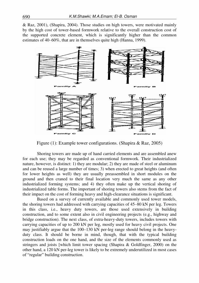
Figure (2): The area carried by one shoring tower.
A number of studies are conducted based on an approach called Rational
Design, which is mean design based on a structured procedure that yields solutions that
both meet the static requirements and are economical. These studies whether general
[e.g., (Peurifoy R. L., 1976), and (Hurd, 1989)] or specific [e.g., (Ringwald, 1985)].
Typically addresses conventional formwork design with a rational approach for
common concrete elements (e.g., regular-height slabs, beams, and walls). Several
studies [e.g., (Christian, 1987), and (Tah & Price, 1991)] have taken the issue even
further and developed computerized solutions. However, one type of conventional
formwork-although widely used-has received little attention with regard to rational
design, this type is formwork for elevated (i.e., heavy and higher than normal)
elements having steel or aluminum shoring towers as the form’s main vertical support.
But all previous studies focused only on giving correct and organized approach
and may some of them computerized they approaches and all these efforts was helpful
and definite introduce methods help in reducing time and cost. This paper will go
further to introduce a method not only structured or computerized but also with
optimization in formwork weight based on genetic algorithms as an optimization tool
to get the optimal solution with the minimum weight which is lead to reducing in time
and cost. Although shoring towers are sometimes used for other purposes than
concrete formwork such as temporary support scaffolds for precast concrete elements
or as access scaffolds for workers, tools, and materials. The present paper treats
shoring towers only as formwork.
Although the similarity between shoring towers in their overall configuration,
dimensions, and basic components, shoring towers from different manufacturers may
vary in some other features such as basic-frame design, assembly method, and carrying
capacity. the present paper works with all kinds of commonly used towers with no
limitations.
For more detailed information on types of shoring towers used in this study
like dimensions, properties, and load carrying capacity, the reader can check the
manufacturers catalogues [e.g., PERI, 1996, DOKA, 2007 and ACROWMISR, 2008].
K.M.Shawki; M.A.Emam; El-B. Osman
692
2. GENETIC ALGORITHMS
The Genetic Algorithms (GAs) was first introduced by John Holland in the 1960s; then
the technique was developed in the University of Michigan during 1960s and 1970s by
Holland and his students. In the beginning, Holland's studies were not oriented to
design an evolutionary algorithm for solving specific problems, but he was just
studying the natural adaptation phenomenon and he was trying to find a method to
simulate its mechanism.
Holland published in 1975 the first book that presents the genetic algorithms; it
was titled “Adaptation in Natural and Artificial Systems”. This book gave a full presentation of the theoretical framework of natural adaptation under the GA, and the
method of simulation of the biological evolution (Holland J. , 1975).
Many scientists worked in the field of GA development and its application
such as, David Goldberg 1989 ... etc. They developed most of the currently known
types of GA, but they all still give Holland the nickname "The father of GAs".
3. OBJECTIVE FUNCTION
The objective function for this problem can be written as follows:
i
n
MTLTUTss
j
WWWWN
WW
1
3B3A
j2B2Ap3B3A2B2A
)l + (l
N × )l + (lW )l + (l )l + (lmin
Where:
Wmin :Minimum overall weight of one unit of formwork (kg).
l2A : Maximum joist span on towers rows (m).
l2B : Maximum joist span between towers rows (m).
l3A : Maximum stringer span on towers rows (m).
l3B : Maximum stringer span between towers rows (m).
Wp : Weight of plywood (kg/m2).
Nj : Number of joist elements per one unit.
Wj : Weight of joist (kg/m).
Ns : Number of stringer elements per one unit.
Ws : Weight of stringer (kg/m).
WUT : Weight of upper tier of shoring tower (kg).
WLT : Weight of lower tier of shoring tower (kg).
n : Number of middle tiers.
WMT : Approximate weight of middle tier of shoring tower (kg).
3.1 Constraints
Three types of constraints are imposed on the generated solutions to ensure the
development of practical formwork elements:
1- Design constraints.
2- Bearing constraints.
3- Stability constrains.
(1)
DESIGN AND CONSTRUCTION OF MULTITIER SHORING… 693
1. Design Constraints
1. The vertical load calculated due to slab condition must be bigger than the minimum
value for vertical loads according to ACI 347R-94 for normal conditions equal 4.8
kPa, when motorized carts are used equal 6.0 kPa if this condition not achieved
takes the minimum value for vertical loads as the design vertical load.
V.L > V.L min (2) 2. The span of the joists lying between the tower rows (also the spacing of the tower
rows) (l2Bmax) must be bigger than L2, where L2 = length of the joist, if this
condition not achieved then recalculate using bigger section of joist.
l2Bmax > L2 (3) 3. The span of the joists lying between the tower rows (also the spacing of the tower
rows) (l2Bmax) must be bigger than L4Y, where L4Y = the length of the tower in
parallel to the direction of the joist, if this condition not achieved then substitute n1
= n1 + 1 and repeat until l2Bmax is obtained that meets the condition.
l2Bmax > L4Y (4) 4. The span of the stringers lying between the towers (also the tower spacing within the
rows). (l3Bmax) must be bigger than L3, where L23 = length of the stringer, if this
condition not achieved then recalculate using bigger section of stringer.
l3Bmax > L3 (5) 5. The safe carrying load capacity of each tower leg (PT) must be bigger the calculated
load carrying capacity per one leg, if this condition not achieved then these solution
unsafe try another one.
PT > V.L × [(l2B + L4y)/2] × [(l3B + L4X)/2] (6)
3.2 Bearing Constraints
1. The calculated bearing stresses between joists and stringers must be smaller than
allowable bearing stress according to type of material for these members see
2. The calculated bearing stresses between stringers and the u-head of the shoring
towers must be smaller than allowable bearing stress according to type of material
for these members.
3.3 Stability Constraints
1. The cross section of the stringers (main beams) must be bigger than the cross
section of the joists (secondary beams).
2. The remain height from the ceiling height after subtracting the height of sheathing,
joist and stringer elements and also after calculating the number of tiers must not
exceed 60 cm (where the 60 cm are the recommended extension for both upper
and lower jack spacers
4. OSAF MODEL
A computer model called OSAF is built using MatLAB to solve formwork problems.
The model is build by G.U.I toolbox to make it easer for the user. The objective
function of this model is to minimize the weight of the overall formwork system. Six
steps are required to run OSAF model as follows:
K.M.Shawki; M.A.Emam; El-B. Osman
694
Step 1 .Run OSAF.
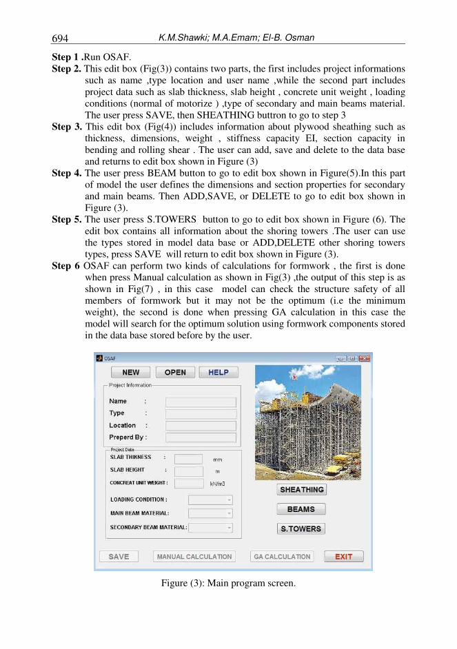
Step 2. This edit box (Fig(3)) contains two parts, the first includes project informations
such as name ,type location and user name ,while the second part includes
project data such as slab thickness, slab height , concrete unit weight , loading
conditions (normal of motorize ) ,type of secondary and main beams material.
The user press SAVE, then SHEATHING buttron to go to step 3
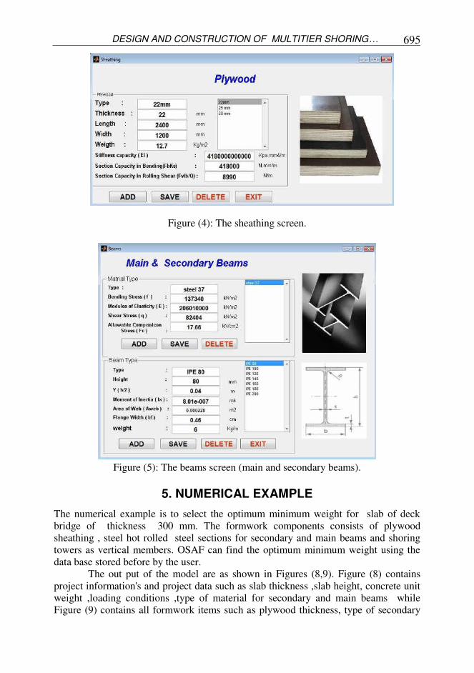
Step 3. This edit box (Fig(4)) includes information about plywood sheathing such as
thickness, dimensions, weight , stiffness capacity EI, section capacity in
bending and rolling shear . The user can add, save and delete to the data base
and returns to edit box shown in Figure (3)
Step 4. The user press BEAM button to go to edit box shown in Figure(5).In this part
of model the user defines the dimensions and section properties for secondary
and main beams. Then ADD,SAVE, or DELETE to go to edit box shown in
Figure (3).
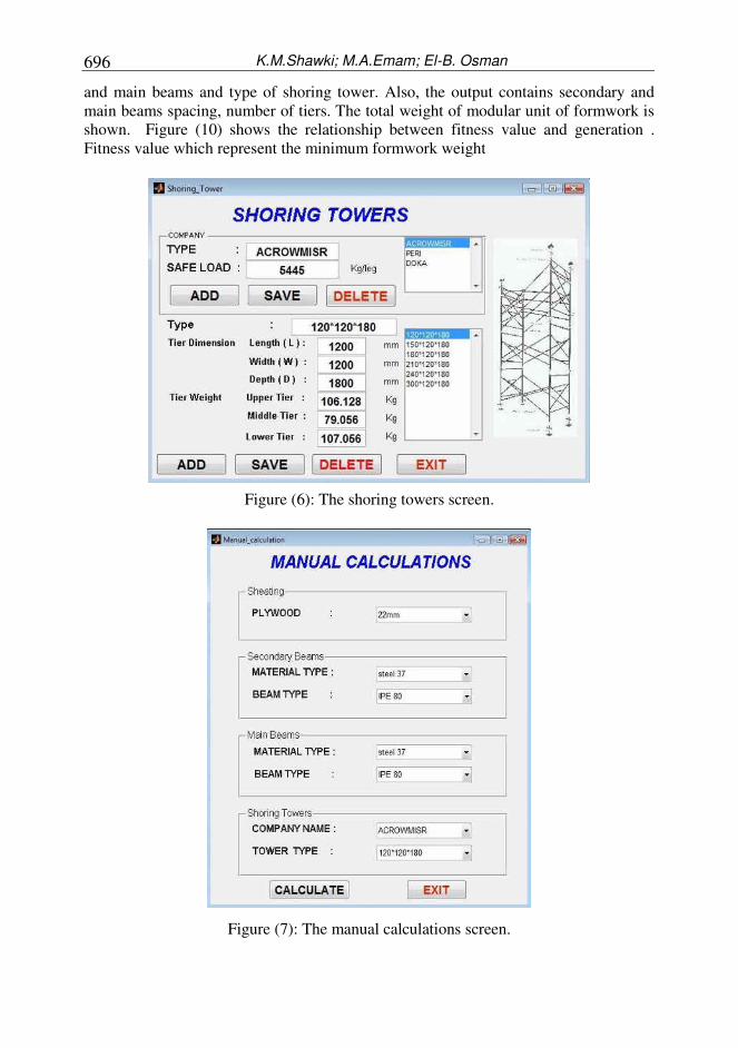
Step 5. The user press S.TOWERS button to go to edit box shown in Figure (6). The
edit box contains all information about the shoring towers .The user can use
the types stored in model data base or ADD,DELETE other shoring towers
types, press SAVE will return to edit box shown in Figure (3).
Step 6 OSAF can perform two kinds of calculations for formwork , the first is done
when press Manual calculation as shown in Fig(3) ,the output of this step is as
shown in Fig(7) , in this case model can check the structure safety of all
members of formwork but it may not be the optimum (i.e the minimum
weight), the second is done when pressing GA calculation in this case the
model will search for the optimum solution using formwork components stored
in the data base stored before by the user.
Figure (3): Main program screen.
DESIGN AND CONSTRUCTION OF MULTITIER SHORING… 695
Figure (4): The sheathing screen.
Figure (5): The beams screen (main and secondary beams).
5. NUMERICAL EXAMPLE
The numerical example is to select the optimum minimum weight for slab of deck
bridge of thickness 300 mm. The formwork components consists of plywood
sheathing , steel hot rolled steel sections for secondary and main beams and shoring
towers as vertical members. OSAF can find the optimum minimum weight using the
data base stored before by the user.
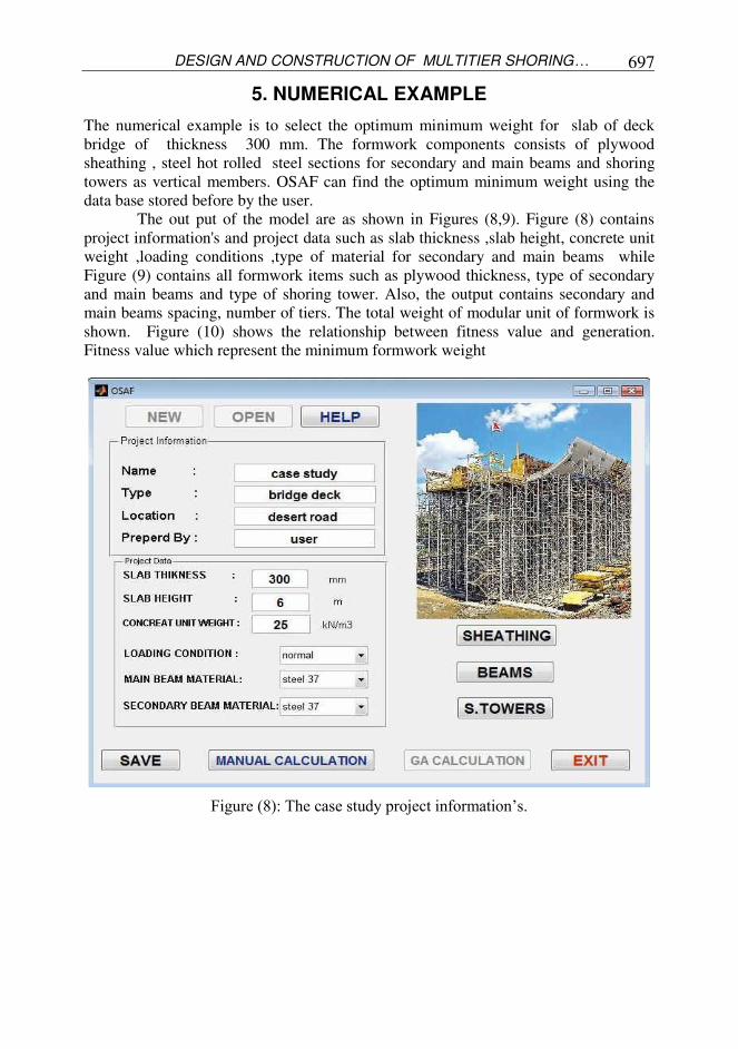
The out put of the model are as shown in Figures (8,9). Figure (8) contains
project information's and project data such as slab thickness ,slab height, concrete unit
weight ,loading conditions ,type of material for secondary and main beams while
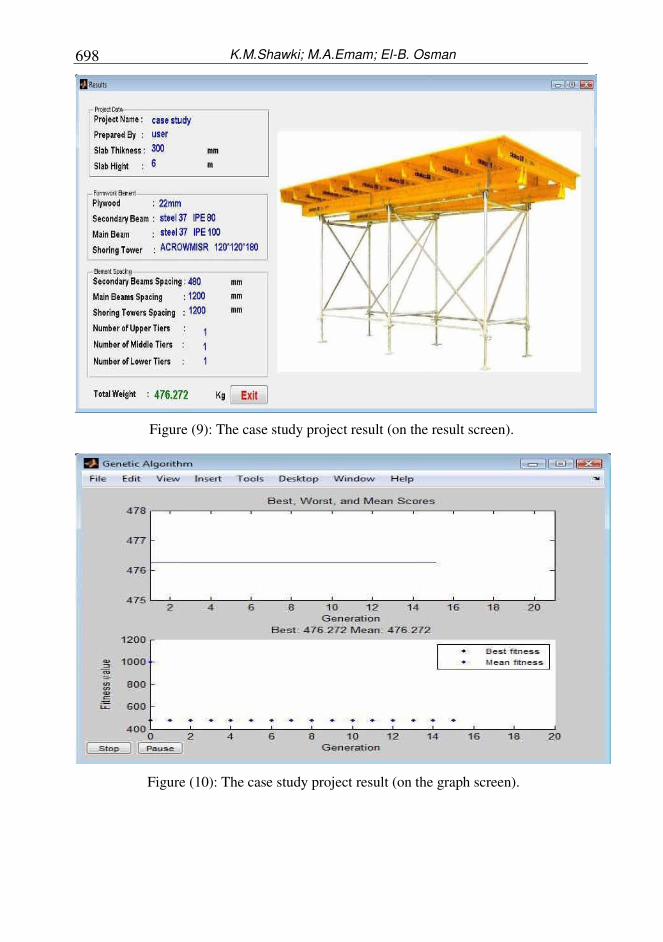
Figure (9) contains all formwork items such as plywood thickness, type of secondary
K.M.Shawki; M.A.Emam; El-B. Osman
696
and main beams and type of shoring tower. Also, the output contains secondary and
main beams spacing, number of tiers. The total weight of modular unit of formwork is
shown. Figure (10) shows the relationship between fitness value and generation .
Fitness value which represent the minimum formwork weight
Figure (6): The shoring towers screen.
Figure (7): The manual calculations screen.
DESIGN AND CONSTRUCTION OF MULTITIER SHORING… 697
5. NUMERICAL EXAMPLE
The numerical example is to select the optimum minimum weight for slab of deck
bridge of thickness 300 mm. The formwork components consists of plywood
sheathing , steel hot rolled steel sections for secondary and main beams and shoring
towers as vertical members. OSAF can find the optimum minimum weight using the
data base stored before by the user.
The out put of the model are as shown in Figures (8,9). Figure (8) contains
project information's and project data such as slab thickness ,slab height, concrete unit
weight ,loading conditions ,type of material for secondary and main beams while
Figure (9) contains all formwork items such as plywood thickness, type of secondary
and main beams and type of shoring tower. Also, the output contains secondary and
main beams spacing, number of tiers. The total weight of modular unit of formwork is
shown. Figure (10) shows the relationship between fitness value and generation.
Fitness value which represent the minimum formwork weight
Figure (8): The case study project information’s.
K.M.Shawki; M.A.Emam; El-B. Osman
698
Figure (9): The case study project result (on the result screen).
Figure (10): The case study project result (on the graph screen).
DESIGN AND CONSTRUCTION OF MULTITIER SHORING… 699
6. CONCLUSION
A computer model (OSAF) has been presented for determining the minimum weight
for heavy and height reinforced concrete slab formwork system. The formwork
consists of plywood sheathing, secondary, main beams and multi tiers shoring towers.
OSAF designed to find the optimum weight using genetic algorithm as an optimizer.
OSAF is easy to use because it depends on numbers of input and out put screen made
through MATLAB. OSAF is tested and use to solve a numerical example as shown
before.
REFERENCES
1. Hurd, M. K. (1995). Formwork for concrete (6th ed.). Michgan: American Concrete
Institute
2. Peurifoy, R. L., & Oberlender, G. D. (1996). Formwork for concrete structures (3rd
ed.). New York: McGraw-Hill
3. Bennett, C. P., & D’Alessio, M. S. (1996). Handbook of temporary structures in construction. New York: McGraw–Hill.
4. Shapira, A. (1995). Formwork design for high elevated slab construction. Journal
of Construction Engineering and Management, 13 (3), 243-252.
5. Shapira, A. (2004). Work inputs and related economic aspects of multitier shoring
towers. Journal of Construction Engineering and Management, 130 (1), 134-142.
6. Shapira, A., & Goldfinger, D. (2000). Work-input model for assembly and
disassembly of high shoring towers. Journal of Construction Engineering and
Management, 18 (4), 467-477.
7. Shapira, A., Shahar, Y., & Raz, Y. (2001). Design and construction of high
multitier shoring towers: case study. Journal of Construction Engineering and
Management, 127 (2), 108-115.
8. Hanna, A. S. (1999). Concrete formwork systems. New York: Marcel Dekker.
9. Peurifoy, R. L. (1976). Formwork for concrete structures (2nd ed.). New York:
McGraw-Hill.
10. Hurd, M. K. (1989). Formwork for concrete. Detroit: American Concrete
Institute.
11. Ringwald, R. (1985). Formwork design. Journal of Construction Engineering and
Management, ASCE , 391-403
12. Christian, J. (1987). Use of integrated microcomputer package for formwork
design. Journal of Construction Engineering and Management, 603-610.
13. Tah, J. H., & Price, A. D. (1991). Interactive-computer-aided formwork design.
Computers and structures, 41 (6), 1157-1167.
14. DOKA. (2007). Products, Know-How, Service. DOKA Gmbh.
15. PERI. (1996). Component Catalogue. PERI Gmbh.
16. Holland, J. (1975). Adaptation in natural and artificial systems. Ann Arbor, Mi.:
University Of Michigan Press.
17. Holland, J. (1992). Genetic Algoritms. Journal of Scientific America, 44-50.
K.M.Shawki; M.A.Emam; El-B. Osman
700
الساندة متعددة الطوابق اأبراجتصميم وتشييد
شائية اصر اا ع لفة ا شدات مرحلة هامة ومؤثرة فى ت مسلحةيعتبر تصميم ا ية ا خرسا فيذ اى مشروع ا د ت عها يجب ان ي ا شائية بااضافة ا احية اا افي من ا تي تحقق اامان ا شدة ا بحث عن ا مهم ا ك فمن ا ذ .و
ون اقتص تي تحقق اقل وزن(. و ت شدات ظهور مع ادية ) هي ا حديثة ا عة ا مص ات ا لشر واعها طبقا ثرة ا و ى توفيرها تى تؤدى ا لفة ا ت وقت وا شدات .ا واع من ا ك يجب استخدام هذ اا ذ واعو ظام ومن هذة اا ا
وية و اخري رئيسية و مرات ثا ون من تطبيق باي وود و م دة اجاابر ا سا متعددة ا طبقات ا -multi) ذات ا
tiers shoring towers)اصر تحميل راسية ة ع حل اامثل فى حا ون فى اغلب ااحوال هى ا تى ت وابارى مرتفعة مثل باطات ا ثقيلة وا باطات ا . ا
ي لمدخا (OSAF MODEL)و قد تم عمل برامج حاسب أ شاشات ت واخرى يحتوى على مجموعة من امشروع مثل اسم مدخات معلومات عن ا تشييد. تشمل شاشة ا دسى ا مه ستخدام لمخرجات وهى سهلة ا
مستخدم و معلومات عن ا وعة واسم ا ة و ا مشروع وم يةباطا خرسا باطة وارتفاعها ات ا فسها مثل سمك اشدة، اصر ا ع مستخدمة مواد ا وعية ا تحميل و رئيسية و متل موادوظروف ا وية و ا ثا مرات ا وع ا تطبيق و ا
ات شر مختلف ا رسية ها اابراج ا مسافات بي تصميم وا د ا تى اختيرت ع اصر ا ع مخرجات ا وتشمل شاشة اتحق تى وضعت هدف ا ة ا له عن طريق ااعتماد على دا اصر( وهذا ع مع ااخذ لشدة ق اقل وزن ي)تقسيط ا
تحميل فى ااعتبار شرو تصميم وا مطلوبة مثل قيود ا قيود ا ل ا حل بحيث تستوفى ط اامان ويتم اخوارزميات ا هدف هذة تم استخدام ا ة ا ية جواارتفاع.وحل دا حل (Genetic Algorithms)ي لحصول على ا
دوال مثلاا وع من ا ما تتميز به من قوة فى حل هذا ا