design and construction of road tunnels: part 2 ... · the design and construction of road tunnels:...
TRANSCRIPT

Design & Construction of Road Tunnels: Part 2 Methodology and Excavation Support Ezekiel Enterprises, LLC
Approved Continuing Education for Licensed Professional Engineers
Design and Construction of Road
Tunnels: Part 2 Methodology
and Excavation Support Five (5) Continuing Education Hours Course #CV7052
EZ-pdh.com Ezekiel Enterprises, LLC
301 Mission Dr. Unit 571 New Smyrna Beach, FL 32170
800-433-1487 [email protected]

Design & Construction of Road Tunnels: Part 2 Methodology and Excavation Support Ezekiel Enterprises, LLC
Course Description:
The Design and Construction of Road Tunnels: Part 2 Methodology and Excavation Support course satisfies five (5) hours of professional development.
The course is designed as a distance learning course that enables the practicing professional engineer to understand road tunnels construction methodology and excavation systems.
Objectives:
The primary objective of this course is enable the student to understand the construction methodology and excavation support systems for cut-and-cover road tunnels, design and construction issues for rock and soft ground tunneling, and the special approaches that must be made when passing through difficult ground.
Grading:
Students must achieve a minimum score of 70% on the online quiz to pass this course. The quiz may be taken as many times as necessary to successful pass and complete the course.
A copy of the quiz questions are attached to last pages of this document.
CHAPTER 5 - CUT AND COVER TUNNELS ....................................................................................5-1
5.1 INTRODUCTION....................................................................................................................5-1
5.2 CONSTRUCTION METHODOLOGY ...................................................................................5-1
5.2.1 General ...................................................................................................................................5-1 5.2.2 Conventional Bottom-Up Construction..................................................................................5-2 5.2.3 Top-Down Construction .........................................................................................................5-3 5.2.4 Selection .................................................................................................................................5-4
5.3
SUPPORT OF EXCAVATION ...............................................................................................5-5
5.3.1 General ...................................................................................................................................5-5 5.3.2
Temporary Support of Excavation .........................................................................................5-6 5.3.3 Permanent Support of Excavation ..........................................................................................5-8 5.3.4
Ground Movement and Impact on Adjoining Structures .....................................................5-11 5.3.5 Base Stability........................................................................................................................5-12
5.4 STRUCTURAL SYSTEMS ...................................................................................................5-12
5.4.1 General .................................................................................................................................5-12 5.4.2 Structural Framing................................................................................................................5-13 5.4.3 Materials...............................................................................................................................5-13 5.4.4 Buoyancy ..............................................................................................................................5-16 5.4.5
Expansion and Contraction Joints ........................................................................................5-16 5.4.6 Waterproofing ......................................................................................................................5-17
5.5 LOADS...................................................................................................................................5-17
5.5.1 General .................................................................................................................................5-17
i
TABLE OF CONTENTS
5.5.2 Load Combinations ..............................................................................................................5-20
5.6 STRUCTURAL DESIGN ......................................................................................................5-24
5.6.1 General .................................................................................................................................5-24 5.6.2 Structural Analysis ...............................................................................................................5-25
5.7 GROUNDWATER CONTROL .............................................................................................5-26
5.7.1 Construction Dewatering......................................................................................................5-26 5.7.2 Methods of Dewatering and Their Typical Applications .....................................................5-27 5.7.3 Uplift Pressures and Mitigation Measures ...........................................................................5-27 5.7.4 Piping and Base Stability .....................................................................................................5-27 5.7.55.7.5 Poten Impact of Area Dewatering ...................................................................................5-28 5.7.6 Groundwater Discharge and Environmental Issues..............................................................5-28
5.8 MAINTENANCE AND PROTECTION OF TRAFFIC ........................................................5-28
5.9 UTILITY RELOCATION AND SUPPORT ..........................................................................5-28
5.9.1 Types of Utilities ..................................................................................................................5-28 5.9.2 General Approach to Utilities During Construction .............................................................5-30
Design & Construction of Road Tunnels: Part 2 Methodology and Excavation Support Ezekiel Eneterprises, LLC

CHAPTER 6 - ROCK TUNNELING.....................................................................................................6-1
6.1
INTRODUCTION....................................................................................................................6-1
6.2
ROCK FAILURE MECHANISM ............................................................................................6-1
6.2.1
Wedge Failure ........................................................................................................................6-2 6.2.2 Stress Induced Failure............................................................................................................6-3 6.2.3 Squeezing and Swelling .........................................................................................................6-4
6.3
ROCK MASS CLASSIFICATIONS........................................................................................6-5
6.3.1
Introduction............................................................................................................................6-5 6.3.2 Terzaghi’s
Classification........................................................................................................6-5 6.3.3 RQD .......................................................................................................................................6-6 6.3.4 Q System ................................................................................................................................6-6 6.3.5 Rock Mass Rating (RMR) System .......................................................................................6-10 6.3.6 Estimation of Rock Mass Deformation Modulus Using Rock Mass Classification ............6-12
6.4
ROCK TUNNELING METHODS.........................................................................................6-13
6.4.1
Drill and Blast ......................................................................................................................6-13 6.4.2 Tunnel Boring Machines (TBM) .........................................................................................6-18
6.4.3 Roadheaders .........................................................................................................................6-23 6.4.4 Other Mechanized Excavation Methods ..............................................................................6-24 6.4.5 Sequential Excavation Method (SEM)/ New Austrian Tunneling Method (NATM) ..........6-24
6.5
TYPES OF ROCK REINFORCEMENT AND EXCAVATION SUPPORT ........................6-24
6.5.1
Excavation Support Options ................................................................................................6-24 6.5.2 Rock Bolts............................................................................................................................6-25
ii
6.5.3 Ribs and Lagging .................................................................................................................6-29 6.5.4 Shotcrete ..............................................................................................................................6-29 6.5.5 Lattice Girder .......................................................................................................................6-30 6.5.6 Spiles and Forepoles ............................................................................................................6-31 6.5.7 Precast Segment Lining .......................................................................................................6-31
6.6 DESIGN AND EVALUATION OF TUNNEL SUPPORTS .................................................6-32
6.6.1 Empirical Method ................................................................................................................6-33 6.6.2 Analytical Methods ..............................................................................................................6-39 6.6.3 Numerical Methods..............................................................................................................6-43 6.6.4 Pre-Support and Other Ground Improvement Methods .......................................................6-47 6.6.5 Sequencing of Excavation and Initial Support Installation ..................................................6-48 6.6.6 Face Stability .......................................................................................................................6-49 6.6.7 Surface Support....................................................................................................................6-49
6.6.8 Ground Displacements .........................................................................................................6-49
Design & Construction of Road Tunnels: Part 2 Methodology and Excavation Support Ezekiel Eneterprises, LLC
6.7
GROUNDWATER CONTROL DURING EXCAVATION .................................................6-50
6.7.1
Dewatering at the Tunnel Face ............................................................................................6-50 6.7.2 Drainage Ahead of Face from Probe Holes .........................................................................6-51 6.7.3 Drainage from Pilot Bore/Tunnel ........................................................................................6-51 6.7.4 Grouting ...............................................................................................................................6-51 6.7.5 Freezing................................................................................................................................6-52 6.7.6 Closed Face Machine ...........................................................................................................6-52 6.7.7 Other Measures of Groundwater Control.............................................................................6-52
6.8
PERMANENT LINING DESIGN ISSUES ...........................................................................6-53
6.8.1
Introduction..........................................................................................................................6-53 6.8.2 Rock Load Considerations ...................................................................................................6-53 6.8.3 Groundwater Load Considerations ......................................................................................6-55
6.8.4 Drained Versus Undrained System ......................................................................................6-59
6.8.5 Uplift Condition ...................................................................................................................6-60 6.8.6 Waterproofing ......................................................................................................................6-61
CHAPTER 7 - SOFTGROUND TUNNELING ....................................................................................7-1
7.1 INTRODUCTION....................................................................................................................7-1
7.2 GROUND BEHAVIOR ...........................................................................................................7-1
7.2.1 Soft Ground Classification .....................................................................................................7-1 7.2.2 Changes of Equilibrium during Construction ........................................................................7-3 7.2.3 The Influence of the Support System on Equilibrium
Conditions .........................................7-5
7.3 EXCAVATION METHODS....................................................................................................7-6
7.3.1 Shield Tunneling ....................................................................................................................7-6
7.3.2 Earth Pressure Balance and Slurry Face Shield Tunnel Boring Machines ............................7-8
iii
7.3.3 Choosing between Earth Pressure Balance Machines and Slurry Tunneling Machines ......7-12 7.3.4 Sequential Excavation Method (SEM).................................................................................7-14
7.4 GROUND LOADS AND ground-SUPPORT interaction ......................................................7-15
7.4.17.4.1 Introdu ..........................................................................................................................7-15 7.4.2 Loads for Initial Tunnel Supports ........................................................................................7-16 7.4.3 Analytical Solutions for Ground-Support Interaction ..........................................................7-17 7.4.4 Numerical Methods..............................................................................................................7-17
7.5 TUNNELING INDUCED SETTLEMENT ...........................................................................7-18
7.5.17.5.1 Introdu ..........................................................................................................................7-18 7.5.2 Sources of Settlement...........................................................................................................7-18 7.5.3 Settlement Calculations........................................................................................................7-19
Design & Construction of Road Tunnels: Part 2 Methodology and Excavation Support Ezekiel Eneterprises, LLC
7.6 IMPACT ON AND PROTECTION OF SURFACE FACILITIES........................................7-23
7.6.1 Evaluation of Structure Tolerance to Settlement .................................................................7-23 7.6.2 Mitigating Settlement...........................................................................................................7-24 7.6.3 Structure Protection..............................................................................................................7-25
7.7 SOIL STABILIZATION AND IMPROVEMENT ................................................................7-25
7.7.1 Purpose.................................................................................................................................7-25 7.7.2 Typical Applications ............................................................................................................7-25 7.7.3 Reinforcement Methods .......................................................................................................7-26 7.7.4 Micropiles ............................................................................................................................7-27 7.7.5 Grouting Methods ................................................................................................................7-27 7.7.6 Ground Freezing ..................................................................................................................7-28
CHAPTER 8 - DIFFICULT GROUND TUNNELING ........................................................................8-1
8.1 INTRODUCTION....................................................................................................................8-1
8.1.1 Instability ...............................................................................................................................8-1 8.1.2 Heavy
Loading .......................................................................................................................8-1 8.1.3 Obstacles and Constraints ......................................................................................................8-1 8.1.4 Physical Conditions ...............................................................................................................8-2
8.2 INSTABILITY .........................................................................................................................8-2
8.2.1 Non-Cohesive Sand and Gravel .............................................................................................8-2 8.2.2 Soft Clay ................................................................................................................................8-4 8.2.3 Blocky Rock...........................................................................................................................8-5 8.2.4 Adverse Combinations of Joints and Shears ..........................................................................8-6 8.2.5 Faults and Alteration Zones ...................................................................................................8-7 8.2.6 Water......................................................................................................................................8-8 8.2.7 Mixed Face Tunneling ...........................................................................................................8-8
8.3 HEAVING LOADING ...........................................................................................................8-10
8.3.1 Squeezing Rock ...................................................................................................................8-10
iv
8.3.2 The Squeezing Process.........................................................................................................8-10 8.3.3 Yielding Supports ................................................................................................................8-12 8.3.4 TBM Tunneling ...................................................................................................................8-14 8.3.5 Steel Rib Support System ....................................................................................................8-15 8.3.6 Concrete Segments...............................................................................................................8-16 8.3.7 TBM Tunneling System .......................................................................................................8-16 8.3.8 Operational Flexibility .........................................................................................................8-18 8.3.9 Swelling ...............................................................................................................................8-18 8.3.10 Swelling Mechanism ............................................................................................................8-18 8.3.11 Other Rock Problems ...........................................................................................................8-18
Design & Construction of Road Tunnels: Part 2 Methodology and Excavation Support Ezekiel Eneterprises, LLC

8.4 OBSTACLES AND CONSTRAINTS ...................................................................................8-19
8.4.1 Boulders ...............................................................................................................................8-19 8.4.2 Karstic Limestone ................................................................................................................8-19 8.4.3 Abandoned Foundations ......................................................................................................8-20 8.4.4 Shallow Tunnels...................................................................................................................8-20
8.5 PHYSICAL CONDITIONS ...................................................................................................8-21
8.5.1 Methane................................................................................................................................8-21 8.5.2 Hydrogen Sulfide .................................................................................................................8-21 8.5.3 High Temperatures...............................................................................................................8-21 8.5.4 Observations ........................................................................................................................8-22
v
Design & Construction of Road Tunnels: Part 2 Methodology and Excavation Support Ezekiel Eneterprises, LLC

CHAPTER 5 CUT AND COVER TUNNELS
5.1 INTRODUCTION This chapter presents the construction methodology and excavation support systems for cut-and-cover road tunnels and describes the structural design in accordance with the AASHTO LRFD Bridge Design Specifications (AASHTO, 2008). The intent of this chapter is to provide guidance in the interpretation of the AASHTO LRFD Specifications in order to have a more uniform application of the code and to provide guidance in the design of items not specifically addressed in AASHTO (2008). The designers must follow the latest LRFD Specifications. A design example illustrating the concepts presented in this chapter can be found in Appendix C. Other considerations dealing with support of excavation, maintenance of traffic and utilities, and control of groundwater and how they affect the structural design are discussed.
5.2 CONSTRUCTION METHODOLOGY
5.2.1 General In a cut and cover tunnel, the structure is built inside an excavation and covered over with backfill material when construction of the structure is complete. Cut and cover construction is used when the tunnel profile is shallow and the excavation from the surface is possible, economical, and acceptable. Cut and cover construction is used for underpasses, the approach sections to mined tunnels and for tunnels in flat terrain or where it is advantageous to construct the tunnel at a shallow depth. Two types of construction are employed to build cut and cover tunnels; bottom-up and top-down. These construction types are described in more detail below. The planning process used to determine the appropriate profile and alignment for tunnels is discussed in Chapter 1 of this manual. Figure 5-1 is an illustration of cut and cover tunnel bottom-up and top-down construction. Figure 5-1(a) illustrates Bottom-Up Construction where the final structure is independent of the support of excavation walls. Figure 5-1(b) illustrates Top-Down Construction where the tunnel roof and ceiling are structural parts of the support of excavation walls.
(a) (b)
Figure 5-1 Cut and Cover Tunnel Bottom-Up Construction (a); Top-Down Construction (b)
5-1
Design & Construction of Road Tunnels: Part 2 Methodology and Excavation Support Ezekiel Eneterprises, LLC

For depths of 30 to 40 feet (about 10 m to 12 m), cut-and-cover is usually more economical and more practical than mined or bored tunneling. The cut-and-cover tunnel is usually designed as a rigid frame box structure. In urban areas, due to the limited available space, the tunnel is usually constructed within a neat excavation line using braced or tied back excavation supporting walls. Wherever construction space permits, in open areas beyond urban development, it may be more economical to employ open cut construction.
Where the tunnel alignment is beneath a city street, the cut-and-cover construction will cause interference with traffic and other urban activities. This disruption can be lessened through the use of decking over the excavation to restore traffic. While most cut-and-cover tunnels have a relatively shallow depth to the invert, depths to 60 feet (18 m) are not uncommon; depths rarely exceed 100 feet (30 m).
Although the support of excavation is an important aspect of cut and cover construction, the design of support of excavation, unless it is part of the permanent structure, is not covered in this chapter.
5.2.2 Conventional Bottom-Up Construction
As shown in Figure 5-2, in the conventional “bottom-up” construction, a trench is excavated from the surface within which the tunnel is constructed and then the trench is backfilled and the surface restored afterward. The trench can be formed using open cut (sides sloped back and unsupported), or with vertical faces using an excavation support system. In bottom-up construction, the tunnel is completed before it is covered up and the surface reinstated.
(a)
(b)
Figure 5-2 Cut-and-Cover Tunnel Bottom-Up (a) and Top-Down (b) Construction Sequence
5-2
Design & Construction of Road Tunnels: Part 2 Methodology and Excavation Support Ezekiel Eneterprises, LLC

Conventional bottom-up sequence of construction in Figure 5-2(a) generally consists of the following steps: Step 1a: Installation of temporary excavation support walls, such as soldier pile and lagging, sheet
piling, slurry walls, tangent or secant pile walls Step 1b: Dewatering within the trench if required Step 1c: Excavation and installation of temporary wall support elements such as struts or tie backs Step 2: Construction of the tunnel structure by constructing the floor; Step 3: Compete construction of the walls and then the roof, apply waterproofing as required; Step 4: Backfilling to final grade and restoring the ground surface. Bottom-up construction offers several advantages: • It is a conventional construction method well understood by contractors.• Waterproofing can be applied to the outside surface of the structure.• The inside of the excavation is easily accessible for the construction equipment and the delivery,
storage and placement of materials.• Drainage systems can be installed outside the structure to channel water or divert it away from the
structure.
Disadvantages of bottom-up construction include: • Somewhat larger footprint required for construction than for top-down construction.• The ground surface can not be restored to its final condition until construction is complete.• Requires temporary support or relocation of utilities.• May require dewatering that could have adverse affects on surrounding infrastructure.
5.2.3 Top-Down Construction
With top-down construction in Figure 5-2 (b), the tunnel walls are constructed first, usually using slurry walls, although secant pile walls are also used. In this method the support of excavation is often the final structural tunnel walls. Secondary finishing walls are provided upon completion of the construction. Next the roof is constructed and tied into the support of excavation walls. The surface is then reinstated before the completion of the construction. The remainder of the excavation is completed under the protection of the top slab. Upon the completion of the excavation, the floor is completed and tied into the walls. The tunnel finishes are installed within the completed structure. For wider tunnels, temporary or permanent piles or wall elements are sometimes installed along the center of the proposed tunnel to reduce the span of the roof and floors of the tunnel. Top-down sequence of construction generally consists of the following steps: Step 1a : Installation of excavation support/tunnel structural walls, such as slurry walls or secant pile walls Step 1b: Dewatering within the excavation limits if required Step 2a: Excavation to the level of the bottom of the tunnel top slab Step 2b: Construction and waterproofing of the tunnel top slab tying it to the support of excavation
walls Step 3a: Backfilling the roof and restoring the ground surface Step 3b: Excavation of tunnel interior, bracing of the support of excavation walls is installed as
required during excavation
5-3
Design & Construction of Road Tunnels: Part 2 Methodology and Excavation Support Ezekiel Eneterprises, LLC
Step 3c: Construction of the tunnel floor slab and tying it to the support of excavation walls; and Step 4 Completing the interior finishes including the secondary walls. Top-down construction offers several advantages in comparison to bottom-up construction: • It allows early restoration of the ground surface above the tunnel• The temporary support of excavation walls are used as the permanent structural walls• The structural slabs will act as internal bracing for the support of excavation thus reducing the amount
of tie backs required• It requires somewhat less width for the construction area• Easier construction of roof since it can be cast on prepared grade rather than using bottom forms• It may result in lower cost for the tunnel by the elimination of the separate, cast-in-place concrete
walls within the excavation and reducing the need for tie backs and internal bracing• It may result in shorter construction duration by overlapping construction activities Disadvantages of top-down construction include: • Inability to install external waterproofing outside the tunnel walls.• More complicated connections for the roof, floor and base slabs.• Potential water leakage at the joints between the slabs and the walls• Risks that the exterior walls (or center columns) will exceed specified installation tolerances and
extend within the neat line of the interior space.• Access to the excavation is limited to the portals or through shafts through the roof.• Limited spaces for excavation and construction of the bottom slab
5.2.4 Selection It is difficult to generalize the use of a particular construction method since each project is unique and has any number of constraints and variables that should be evaluated when selecting a construction method. The following summary presents conditions that may make a one construction method more attractive than the other. This summary should be used in conjunction with a careful evaluation of all factors associated with a project to make a final determination of the construction method to be used. Conditions Favorable to Bottom-Up Construction: • No right-of way restrictions• No requirement to limit sidewall deflections• No requirement for permanent restoration of surface Conditions Favorable to Top-Down Construction • Limited width of right-of-way • Sidewall deflections must be limited to protect adjacent features• Surface must be restored to permanent usable condition as soon as possible
5-4
Design & Construction of Road Tunnels: Part 2 Methodology and Excavation Support Ezekiel Eneterprises, LLC
5.3 SUPPORT OF EXCAVATION
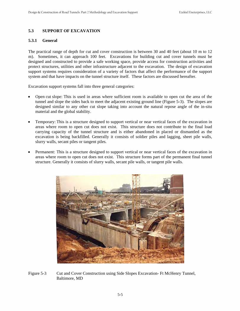
5.3.1 General The practical range of depth for cut and cover construction is between 30 and 40 feet (about 10 m to 12 m). Sometimes, it can approach 100 feet. Excavations for building cut and cover tunnels must be designed and constructed to provide a safe working space, provide access for construction activities and protect structures, utilities and other infrastructure adjacent to the excavation. The design of excavation support systems requires consideration of a variety of factors that affect the performance of the support system and that have impacts on the tunnel structure itself. These factors are discussed hereafter. Excavation support systems fall into three general categories: • Open cut slope: This is used in areas where sufficient room is available to open cut the area of the
tunnel and slope the sides back to meet the adjacent existing ground line (Figure 5-3). The slopes aredesigned similar to any other cut slope taking into account the natural repose angle of the in-situmaterial and the global stability.
• Temporary: This is a structure designed to support vertical or near vertical faces of the excavation in
areas where room to open cut does not exist. This structure does not contribute to the final loadcarrying capacity of the tunnel structure and is either abandoned in placed or dismantled as theexcavation is being backfilled. Generally it consists of soldier piles and lagging, sheet pile walls,slurry walls, secant piles or tangent piles.
• Permanent: This is a structure designed to support vertical or near vertical faces of the excavation in
areas where room to open cut does not exist. This structure forms part of the permanent final tunnelstructure. Generally it consists of slurry walls, secant pile walls, or tangent pile walls.
Figure 5-3 Cut and Cover Construction using Side Slopes Excavation- Ft McHenry Tunnel, Baltimore, MD
5-5
Design & Construction of Road Tunnels: Part 2 Methodology and Excavation Support Ezekiel Eneterprises, LLC

This section discusses temporary and permanent support of excavation systems and provides issues and concerns that must be considered during the development of a support of excavation scheme. The design of open-cut slopes and support of excavation are not in the scope of this manual. Information on the design of soil and rock slopes can be found in FHWA-NHI-05-123 “Soil Slope and Embankment Design” (FHWA, 2005d), and NHI-99-007 “Rock Slopes” (FHWA, 1999), respectively. Supports of Excavation are referred to FHWA-NHI-05-046 “Earth Retaining Structure” (FHWA, 2005e). Many of the issues described below associated with ground and groundwater behavior are applicable to side slopes also.
5.3.2 Temporary Support of Excavation
Support of excavation structures can be classified as flexible or rigid. Flexible supports of excavation include sheet piling and soldier pile and lagging walls. A careful site investigation that provides a clear understanding of the subsurface conditions is essential to determining the correct support system. Rigid support of excavation such as slurry walls, secant piles or tangent piles are also used as temporary support of excavation. Descriptions of these systems are provided Section 5.3.3 Permanent Support of Excavation.
A sheet piling wall consists of a series of interlocking sheets that form a corrugated pattern in the plan view of the wall. The sheets are either driven or vibrated into the ground. The sheets extend well below the bottom of the excavation for stability. These sheets are fairly flexible and can support only small heights of earth without bracing. As the excavation progresses, bracings or tie backs are installed at specified intervals. Sheet pile walls can be installed quickly and easily in ideal soil conditions. The presence of rock, boulders, debris, utilities, or obstructions will make the use of sheet piling difficult since these features will either damage the sheet pile or in the case of a utility, be damaged by the sheet pile. Figure 5-4 shows a sheet pile wall with complex multi level internal bracing.
Figure 5-4 Sheet Pile Walls with Multi Level-Bracing
5-6
Design & Construction of Road Tunnels: Part 2 Methodology and Excavation Support Ezekiel Eneterprises, LLC

A soldier pile wall consists of structural steel shape columns spaced 4 to 8 feet apart and driven into the ground or placed in predrilled holes. The soldier piles extend well below the level of the bottom of excavation for stability. As the excavation progresses, lagging is placed between the soldier piles to retain the earth behind the wall. The lagging could be timber or concrete planks. The soldier piles are relatively flexible and are capable of supporting only modest heights of earth without bracing. As the excavation progresses, bracing or tie backs are installed at specified intervals. Soldier piles can also be installed in more different ground conditions than can a sheet pile wall. The spacing allows the installation of piles around utilities. The finite dimension of the pile allows drilling of holes through obstructions and into rock, making the soldier pile and lagging wall more versatile than the sheet pile wall. Figure 5-5 shows a braced soldier pile and lagging wall.
Figure 5-5 Braced Soldier Pile and Lagging Wall
Support of excavation bracing can consist of struts across the excavation to the opposite wall, knee braces that brace the wall against the ground, and tie backs consisting of rock anchors or soil anchors that tie the wall back into the earth behind the wall. Struts and braces extend into the working area and create obstacles to the construction of the tunnel. Tie backs do not obstruct the excavation space but sometimes they extend outside of the available right-of-way requiring temporary underground easements. They may also encounter obstacles such as boulders, utilities or building foundations. The suitability of tie backs depends on the soil conditions behind the wall. The site conditions must be studied and understood and taken into account when deciding on the appropriate bracing method. Figure 5-6 shows an excavation braced by tie-backs, leaving the inside of the excavation clear for construction activities. The design and detailing of the support of excavation must consider the sequence of installation and account for the changing loading conditions that will occur as the system is installed. The design of temporary support of excavation is not in the scope of this manual. The information presented herein is intended to make tunnel designers aware of the impact that the selected support of excavation can have on the design, constructability and serviceability of the tunnel structure. Guidance on the design of support of excavation can be found in FHWA-NHI-05-046 “Earth Retaining Structure” (FHWA, 2005e).
5-7
Design & Construction of Road Tunnels: Part 2 Methodology and Excavation Support Ezekiel Eneterprises, LLC

Figure 5-6 Tie-back Excavation Support leaves Clear Access
Use of temporary support of excavation does have the advantage of allowing waterproofing to be applied to the outside face of the tunnel structure. This can be accomplished by setting the face of the support of excavation away from the outside face of the tunnel structure. This space provides room for forming and allows the placement of waterproofing directly onto the finished outside face of the structure. As an alternate, the face of the support of excavation can be placed directly adjacent to the outside face of the structure. Under this scenario, the face of the support of excavation is used as the form for the tunnel structure. Waterproofing is installed against the support of excavation and concrete is poured against the waterproofing. In this case, the temporary support of excavation wall is abandoned in place.
5.3.3 Permanent Support of Excavation Permanent support of excavation typically employs rigid systems. Rigid systems consist of slurry walls, soldier pile tremie concrete (SPTC) walls, tangent pile walls, or secant pile walls. As with temporary support of excavation systems, a careful site investigation that provides a clear understanding of the subsurface conditions is essential to determining the appropriate system. A slurry wall is constructed by excavating a trench to the thickness required for the external structural wall of the tunnel. Slurry walls are usually 30 to 48 inches thick. The trench is kept open by the placement of bentonite slurry in the trench as it is excavated. The trench will typically extend for some distance below the bottom of the tunnel structure for stability. Reinforcing steel is lowered into the slurry filled trench and concrete is then placed using the tremie method into the trench displacing the slurry. The resulting wall will eventually be incorporated into the final tunnel structure. Excavation proceeds from the original ground surface down to the bottom of the roof of the tunnel structure. The tunnel roof is constructed and tied into the slurry wall. The tunnel roof provides bracing for the slurry wall. Depending on the depth of the tunnel, the roof could be the first level of bracing or an intermediate level. The excavation would then proceed and additional bracing would be provided as needed. At the base of the excavation, the tunnel bottom slab is then constructed and tied into the walls. Figure 5-7 shows a slurry wall supported excavation in an urban area.
5-8
Design & Construction of Road Tunnels: Part 2 Methodology and Excavation Support Ezekiel Eneterprises, LLC
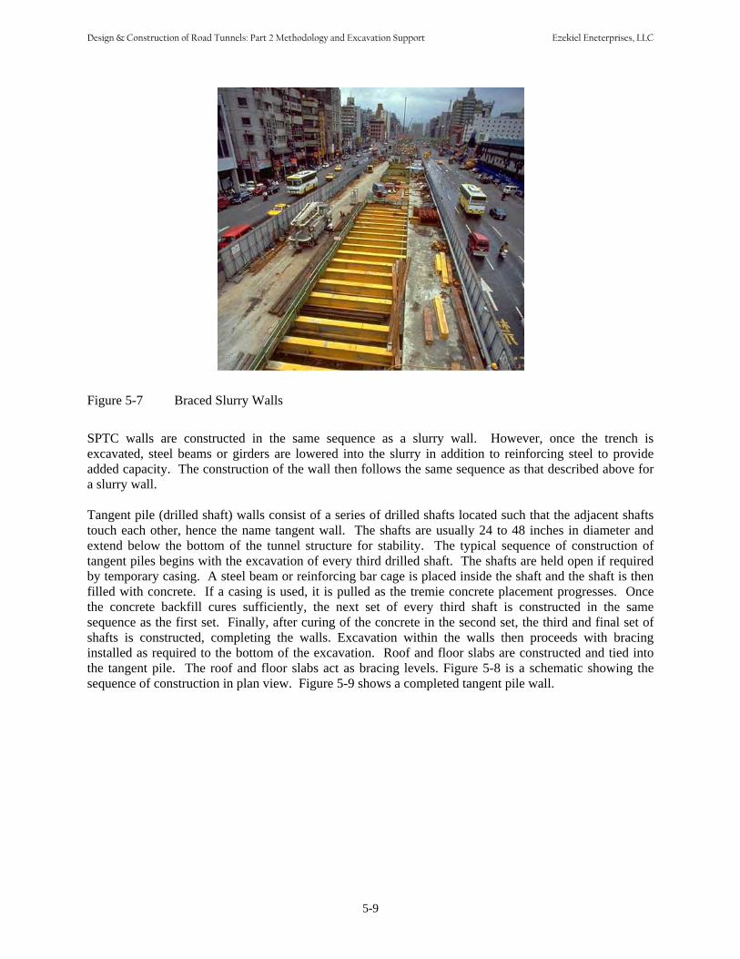
Figure 5-7 Braced Slurry Walls
SPTC walls are constructed in the same sequence as a slurry wall. However, once the trench is excavated, steel beams or girders are lowered into the slurry in addition to reinforcing steel to provide added capacity. The construction of the wall then follows the same sequence as that described above for a slurry wall. Tangent pile (drilled shaft) walls consist of a series of drilled shafts located such that the adjacent shafts touch each other, hence the name tangent wall. The shafts are usually 24 to 48 inches in diameter and extend below the bottom of the tunnel structure for stability. The typical sequence of construction of tangent piles begins with the excavation of every third drilled shaft. The shafts are held open if required by temporary casing. A steel beam or reinforcing bar cage is placed inside the shaft and the shaft is then filled with concrete. If a casing is used, it is pulled as the tremie concrete placement progresses. Once the concrete backfill cures sufficiently, the next set of every third shaft is constructed in the same sequence as the first set. Finally, after curing of the concrete in the second set, the third and final set of shafts is constructed, completing the walls. Excavation within the walls then proceeds with bracing installed as required to the bottom of the excavation. Roof and floor slabs are constructed and tied into the tangent pile. The roof and floor slabs act as bracing levels. Figure 5-8 is a schematic showing the sequence of construction in plan view. Figure 5-9 shows a completed tangent pile wall.
5-9
Design & Construction of Road Tunnels: Part 2 Methodology and Excavation Support Ezekiel Eneterprises, LLC

Figure 5-8 Tangent Pile Wall Construction Schematic
Figure 5-9 Tangent Pile Wall Support
Secant pile walls are similar to tangent pile walls except that the drilled shafts overlap each other rather than touch each other. This occurs because the center to center spacing of secant piles is less than the
5-10
Design & Construction of Road Tunnels: Part 2 Methodology and Excavation Support Ezekiel Eneterprises, LLC
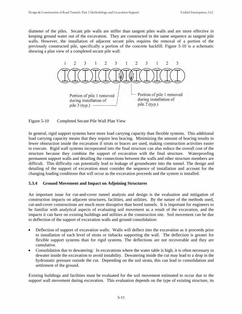
diameter of the piles. Secant pile walls are stiffer than tangent piles walls and are more effective in keeping ground water out of the excavation. They are constructed in the same sequence as tangent pile walls. However, the installation of adjacent secant piles requires the removal of a portion of the previously constructed pile, specifically a portion of the concrete backfill. Figure 5-10 is a schematic showing a plan view of a completed secant pile wall.
Figure 5-10 Completed Secant Pile Wall Plan View
In general, rigid support systems have more load carrying capacity than flexible systems. This additional load carrying capacity means that they require less bracing. Minimizing the amount of bracing results in fewer obstruction inside the excavation if struts or braces are used, making construction activities easier to execute. Rigid wall systems incorporated into the final structure can also reduce the overall cost of the structure because they combine the support of excavation with the final structure. Waterproofing permanent support walls and detailing the connections between the walls and other structure members are difficult. This difficulty can potentially lead to leakage of groundwater into the tunnel. The design and detailing of the support of excavation must consider the sequence of installation and account for the changing loading conditions that will occur as the excavation proceeds and the system is installed.
5.3.4 Ground Movement and Impact on Adjoining Structures
An important issue for cut-and-cover tunnel analysis and design is the evaluation and mitigation of construction impacts on adjacent structures, facilities, and utilities. By the nature of the methods used, cut-and-cover constructions are much more disruptive than bored tunnels. It is important for engineers to be familiar with analytical aspects of evaluating soil movement as a result of the excavation, and the impacts it can have on existing buildings and utilities at the construction site. Soil movement can be due to deflection of the support of excavation walls and ground consolidation: • Deflection of support of excavation walls: Walls will deflect into the excavation as it proceeds prior
to installation of each level of struts or tiebacks supporting the wall. The deflection is greater for flexible support systems than for rigid systems. The deflections are not recoverable and they are cumulative.
• Consolidation due to dewatering: In excavations where the water table is high, it is often necessary todewater inside the excavation to avoid instability. Dewatering inside the cut may lead to a drop in the hydrostatic pressure outside the cut. Depending on the soil strata, this can lead to consolidation andsettlement of the ground.
Existing buildings and facilities must be evaluated for the soil movement estimated to occur due to the support wall movement during excavation. This evaluation depends on the type of existing structure, its
5-11
Design & Construction of Road Tunnels: Part 2 Methodology and Excavation Support Ezekiel Eneterprises, LLC

distance and orientation from the excavation, the soil conditions, the type of foundations of the structure, and other parameters. The analysis is site specific, and it can be very complex. Empirical methods and screening tools are available to more generally characterize the potential impacts. The existing buildings and facilities within the zone of influence must be surveyed (Chapter 3) and monitored as discussed in Chapter 15 Geotechnical and Structural Instrumentation. Measures to deal with this issue include: • Design of stiffer and more watertight excavation support walls.• Provide more closely spaced and stiffer excavation support braces and/or tiebacks.• Use of pre-excavation soil improvement.• Underpinning of existing structures.• Provide monitoring and instrumentation program during excavation.• Establish requirement for mitigation plans if movements approach allowable limits.
5.3.5 Base Stability
Poor soil beneath the excavation bottom may require that the excavation support structure be extended down to a more competent stratum to ensure the base stability of the structure. This may depend upon whether the earth pressures applied to the wall together with its weight can be transferred to the surrounding soil through a combination of adhesion (side friction) and end bearing. Soft clays below the excavation are particularly susceptible to yielding causing the bottom of the excavation to heave with a potential settlement at the ground surface, or worse to blow up. High groundwater table outside of the excavation can result in base instability as well. Measures to analyze the subsurface condition, and provide sufficient base stability must be addressed by the geotechnical engineer and/or tunnel designer. Readers are referred to FHWA-NHI-05-046 “Earth Retaining Structure” (FHWA, 2005e) for more details.
5.4 STRUCTURAL SYSTEMS
5.4.1 General A structural system study is often prepared to determine the most suitable structural alternatives for the construction of the cut-and-cover tunnel. This involves a determination of the proposed tunnel section as discussed in Chapter 2, the excavation support system, the tunnel structural system, the construction method (top-down vs. bottom up), and the waterproofing system. Each of these elements is interdependent upon the other. Options for each element are discussed below. The system study should consider all options that are feasible in a holistic approach, taking into account the effect that one option for an element has on another element.
5.4.1.1 Structural Element Sizing As described in Chapter 1, the shape of the cut and cover tunnels is generally rectangular. The dimensions of the rectangular box must be sufficient to accommodate the clearance requirements (Chapter 2). Dimensional information required for structural sizing includes wall heights and the span lengths of the roof. The width of the tunnel walls added to the clear space width requirements will determine the final width of the excavation required to construct the tunnel. To minimize the horizontal width of the excavation the support of excavation can be incorporated as part of, the final structure.
5-12
Design & Construction of Road Tunnels: Part 2 Methodology and Excavation Support Ezekiel Eneterprises, LLC
However, this might have negative impacts on the watertightness of the structure. Some reasons that would require minimization of the out to out width of the excavation are: • Limited horizontal right-of-way. In urban areas where tunnels are constructed along built up city
streets, additional right-of-way may be impractical to obtain. There may be existing buildingsfoundations adjacent to the tunnel or utilities that are impractical to move.
• There may be natural features that make a wider excavation undesirable or not feasible such as rock or bodies of water.
The depth of the roof and floor combined with the clearance requirements will define the vertical height of the tunnel structure, the depth of excavation required, and the height of the associated support of excavation. It is recommended in cut-and-cover construction that the tunnel depth be minimized to reduce the overall cost which extends beyond the cost of the tunnel structure. A shallower profile grade can also result in shorter approaches and approach grades that are more favorable to the operational characteristics of the vehicles using the tunnel resulting in lower costs for the users of the tunnel.
5.4.2 Structural Framing
The framing model for the tunnel will be different according to whether the support of excavation walls is a temporary (non-integral) or a permanent (integral) part of the final structure. With temporary support of excavation walls, the tunnel section would be considered a frame with fixed joints. When support of excavation walls are to form part of the tunnel structure, fixed connections between the support of excavation walls and the rest of the structure may be difficult to achieve in practice; partial fixity is more probable, but to what degree may be difficult to define. A range of fixities may need to be considered in the design analysis. Corners of rectangular tunnels often incorporate haunches to increase the member’s shear capacity near the support, in effect creating more of an arched shape. A true arch shape provides an efficient solution for the tunnel roof but tends to create other issues. Flat arches result in horizontal loads at the spring line that must be resisted by the walls. Semicircular arches eliminate these forces but result in a section larger than required vertically and drive down the tunnel profile which will add cost. When using temporary support of excavation walls, the tunnel section is constructed totally within them, often with a layer of waterproofing completely enveloping the section. In contrast, when the support of excavation walls become part of the final structure, an enveloping membrane is difficult to achieve. Therefore, provisions for overlapping, enveloping and sealing the joints would be needed. Furthermore, physical keying of the structural top and bottom slabs into the support of excavation walls is essential for any transmission of moments and shear. Some old tunnels employ a structural system consisting of transverse structural steel frames spaced about 5 feet (1.5 m) apart. Typically, these frames are embedded in un-reinforced cast-in-place floors and walls, while for the roof, these frames are exposed and support a cast-in-place roof slab. This type of construction may still be competitive when applied to shallow tunnels, especially when longer roof spans are required for multiple lane cross sections. More details on these issues are provided in the following paragraphs that described specific materials for construction.
5.4.3 Materials Cast-in-place concrete is the most common building material used in cut and cover tunnel construction, however other materials such as precast prestressed concrete, post tensioned concrete and structural steel are used. These materials and their application are discussed below.
5-13
Design & Construction of Road Tunnels: Part 2 Methodology and Excavation Support Ezekiel Eneterprises, LLC
5.4.3.1 Cast-in-Place Concrete
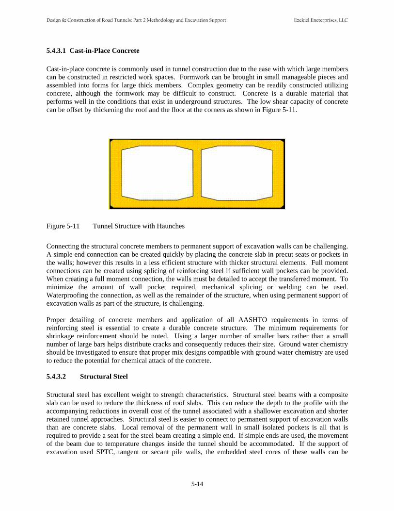
Cast-in-place concrete is commonly used in tunnel construction due to the ease with which large members can be constructed in restricted work spaces. Formwork can be brought in small manageable pieces and assembled into forms for large thick members. Complex geometry can be readily constructed utilizing concrete, although the formwork may be difficult to construct. Concrete is a durable material that performs well in the conditions that exist in underground structures. The low shear capacity of concrete can be offset by thickening the roof and the floor at the corners as shown in Figure 5-11.
Figure 5-11 Tunnel Structure with Haunches
Connecting the structural concrete members to permanent support of excavation walls can be challenging. A simple end connection can be created quickly by placing the concrete slab in precut seats or pockets in the walls; however this results in a less efficient structure with thicker structural elements. Full moment connections can be created using splicing of reinforcing steel if sufficient wall pockets can be provided. When creating a full moment connection, the walls must be detailed to accept the transferred moment. To minimize the amount of wall pocket required, mechanical splicing or welding can be used. Waterproofing the connection, as well as the remainder of the structure, when using permanent support of excavation walls as part of the structure, is challenging. Proper detailing of concrete members and application of all AASHTO requirements in terms of reinforcing steel is essential to create a durable concrete structure. The minimum requirements for shrinkage reinforcement should be noted. Using a larger number of smaller bars rather than a small number of large bars helps distribute cracks and consequently reduces their size. Ground water chemistry should be investigated to ensure that proper mix designs compatible with ground water chemistry are used to reduce the potential for chemical attack of the concrete.
5.4.3.2 Structural Steel Structural steel has excellent weight to strength characteristics. Structural steel beams with a composite slab can be used to reduce the thickness of roof slabs. This can reduce the depth to the profile with the accompanying reductions in overall cost of the tunnel associated with a shallower excavation and shorter retained tunnel approaches. Structural steel is easier to connect to permanent support of excavation walls than are concrete slabs. Local removal of the permanent wall in small isolated pockets is all that is required to provide a seat for the steel beam creating a simple end. If simple ends are used, the movement of the beam due to temperature changes inside the tunnel should be accommodated. If the support of excavation used SPTC, tangent or secant pile walls, the embedded steel cores of these walls can be
5-14
Design & Construction of Road Tunnels: Part 2 Methodology and Excavation Support Ezekiel Eneterprises, LLC

exposed and a full moment connection can be made. A full moment connection will not allow temperature movements, so the resulting force effects must be evaluated and accommodated by design. Structural steel beams are best fabricated and delivered in a single piece. However, if the excavation support system has complex internal bracing, it may not be possible to deliver and erect the steel beams inside the excavation which would require splicing of the steel beams. Connections also require careful inspection which adds to the future maintenance cost of the tunnel if the connections are not encased. Waterproofing the connections to the exterior walls can be difficult. Tunnels typically produce a damp environment, if combined with the potential to leak around connections, this results in conditions that can result in aggressive corrosion to steel members. Corrosion protection must be considered as part of the structural steel structural system. In addition to the roof structure described above, steel frames have also been used in road tunnels and under some circumstances, may still be appropriate. The frame includes columns and the roof beams. In permanent support walls, the columns would be embedded in the walls. The steel columns are erected on a suitable foundation cast on the bottom of the excavation, the beams are then erected and joined with the columns and the entire frames are then encased in concrete, with nominal reinforcement. The roof beams can be completely encased or exposed supporting a thin concrete roof slab. If exposed, inspection and maintenance are required.
5.4.3.3 Prestressed Concrete Prestressed concrete, including precast prestressed beams such as AASHTO beams or similar, may be suitable for large roof spans when clearances are tight and the overall depth of section must be limited. Precast prestressed beams have been used for the top slab supported on cast in place walls. Precast concrete beams, in the number and lengths required for cut and cover tunnels are impractical to splice. They must be delivered in a single piece and be able to be erected within the space available inside the excavation. The type and configuration of the excavation must therefore be considered when evaluating the use of precast concrete beams. Making connections with permanent support of excavation walls can be accomplished by creating pockets in the walls to support the beams in a simple support arrangement. Simple supports also require a method for allowing movement of the beams during temperature changes inside the tunnel. Waterproofing this connection is difficult. Making a moment connection requires more elaborate details of the junction between the wall and the beam to be able to install the reinforcing required for the moment connection. A moment connection at the beam also requires that the wall itself be capable of accepting the moment transferred by the beam. Therefore the detailing of the wall must be compatible with the structural system selected. A full moment connection will not allow temperature movements, so the resulting force effects must be evaluated and accommodated by the design. Although seldom, post tensioning is used in cut and cover tunnels; however in developing the post tensioning strategy, it is important to consider the various loading stages and potentially have multiple stages of post tensioning. For example, the introduction of high post-tensioning forces in tunnel slabs before backfilling causes temporary high tensile stresses in the opposite face of the slabs. These stresses may limit the depth to which post-tensioned members can be used, unless some of the tendons are tensioned from inside the box after backfilling. The elastic shortening of the slab will induce resistance to the post-tensioning via the walls, and should be taken into consideration. The additional moments created will also need to be resisted. Isolating the top slab from the walls by means of a movement joint (such as neoprene or Teflon bearings) would eliminate the above shortcomings but also eliminate the advantages of moment connection; waterproofing of the movement joint will need to be addressed. The design should identify space requirements for operation of the stressing jacks from both sides (if required). In many cases, the tendon would be less than 100 ft (30 m) long, needing only one end for stressing. Usually, in such a case, alternate strands would be stressed from alternate ends, requiring suitable space on each side.
5-15
Design & Construction of Road Tunnels: Part 2 Methodology and Excavation Support Ezekiel Eneterprises, LLC
5.4.4 Buoyancy
Buoyancy is a major concern in shallow tunnels that are under or partially within the water table. Buoyancy should be checked during the design. The structural system selected should take into account its ability to resist buoyancy forces with its own weight or by providing measures to deal with negative buoyancy. In cases where the structure and backfill are not heavy enough to resist the buoyancy forces, flotation can occur. Measures to resist the forces of flotation must be provided and accounted for in the design. The resistance against flotation can be achieved by a variety of methods. Typical methods used to increase the effective weight of the structure include: • Connecting the structure to the excavation support system and thus mobilizing its weight and/or its
friction with the ground• Thickening structural members beyond what is required for strength in order to provide dead load to
counter the flotation forces• Widening the floor slab of the tunnel beyond the required footprint to key it into adjacent soil and
thus to include the weight of soil above these protrusions• Using steel or concrete tension piles to resist the uplift forces associated with flotation• Using permanent tie-down anchors; in soils, it may be prudent for the anchors only to carry a nominal
tension under normal conditions and for the anchors to be fully mobilized only under extremeconditions. Properly protected anchor heads can be located in formed recesses within the base slab
• Permanent pressure relief system beneath the base of the structure. This is a complicated system to remove the buoyant forces by allowing water to be collected from under the bottom slab and removed from the tunnel. This type of system requires maintenance and redundancy in addition to the lifecycle costs associated with operating the system. It can also have the effect of lowering the local groundwater table which may have negative consequences.
Considering the long design life of underground structures, the design of tension piles or tie-down anchors to resist flotation forces must include provisions to address the risk of corrosion of these tension elements and consideration of their connection to the tunnel structure. Similarly, the use of an invert pressure relief system and backup system must include provisions to address the risk of the long-term operation and maintenance requirements. For most projects, generally, buoyancy forces are resisted by increased dead load of the structure and/or weight of fill above the structure.
5.4.5 Expansion and Contraction Joints
Many cut and cover tunnels are constructed without permanent expansion or contraction joints. Although expansion joints may not be required except close to the portals, contraction joints are recommended throughout the tunnel. Significant changes in support stiffness or surcharge can cause differential settlement. If the induced moments and shears resulting from this are greater than the section can handle, relieving joints can be used to accommodate localized problems. Expansion joints are usually provided at the interfacing with ventilation building or portals or other rigid structures to allow for differential settlements and movements associated with temperature changes. It is recommended that contraction joints be placed at intervals of approximately 30 feet (about 9 m). Seismic loading can cause significant bending moments in cut and cover tunnels. Joints may be used to relieve the moments and shears that would have occurred in continuous rigid structures, particularly as the width (and hence the stiffness) of the structure increases. Joints may also be required to handle relative seismic motion at locations where the cross-sectional properties change significantly, such as at
5-16
Design & Construction of Road Tunnels: Part 2 Methodology and Excavation Support Ezekiel Eneterprises, LLC
ventilation buildings and portals. Such motion can be both longitudinal and transverse (horizontal and vertical) to the tunnel. Joints are potential areas were leaks can occur. As such, they are potential sources of high maintenance costs over the life of the tunnel. The number of joints should be minimized and special care should be taken in the detailing of joints to ensure water tightness. The type and frequency of joints required will be a function of the structural system required and should be evaluated in the overall decision of the type selected.
5.4.6 Waterproofing
The existence of a high groundwater table or water percolating down from above requires that tunnels be waterproof. Durability is improved when the tunnel is waterproof. Good waterproofing design is also imperative to keep the tunnel dry and reduce future maintenance. Leaking tunnels are unsightly and can give rise to concern by users. In colder climates such as in the North East, leaks can become hazardous ceiling icicles or ice patches on roadways. Tunnel waterproofing is discussed breifly in Chapter 10. The waterproofing system should be selected based on the required performance and its compatibility with the structural system.
5.5 LOADS
5.5.1 General
The relevant loads to be considered in the design of the cut and cover tunnel structures along with how to combine the loads are given in Section 3 of the AASHTO LRFD specifications. Section 3 of the AASHTO LRFD specification divides loads into two categories: Permanent Loads and Transient Loads. Paragraph 3.3.2 “Load and Load Designation” of the AASHTO LRFD specifications defines following permanent loads that are applicable to the design of cut and cover tunnels: DC = Dead Load: This load comprises the self weight of the structural components as well as the loads
associated with nonstructural attachments. Nonstructural attachments can be signs, lighting fixtures, signals, architectural finishes, waterproofing, etc. Typical unit weights for common building materials are given in Table 3.5.1-1 of the AASHTO LRFD specifications. Actual weights for other items should be calculated based on their composition and configuration.
DW = Dead Load: This load comprises the self weight of wearing surfaces and utilities. Utilities in
tunnels can include power lines, drainage pipes, communication lines, water supply lines, etc. Wearing surfaces can be asphalt or concrete. Dead loads, wearing surfaces and utilities should calculate based on the actual size and configuration of these items.
EH = Horizontal Earth Pressure Load. The information required to calculate this load is derived by the
geotechnical data developed during the subsurface investigation program. In lieu of actual subsurface data, the information contained in paragraph 3.11 of the AASHTO specifications can be used. At-rest pressures should be used in the design of cut and cover tunnel structure.
EL = Accumulated locked-in force effects resulting from the construction process including secondary
forces from post tensioning if used.
5-17
Design & Construction of Road Tunnels: Part 2 Methodology and Excavation Support Ezekiel Eneterprises, LLC

ES = Earth surcharge load. This is the vertical earth load due to fill over the structure that was placed above the original ground line. It is recommended that a minimum surcharge load of 400 psf be used in the design of cut and cover tunnels. If there is a potential for future development over the tunnel structure, the surcharge from the actual development should be used in the design of the structure. In lieu of a well defined loading, it is recommended that a minimum value of 1000 psf be used when future development is anticipated.
EV = Vertical pressure from the dead load of the earth fill. This is the vertical earth load due to fill
over the structure up to the original ground line. The information required to calculate this load are derived by the geotechnical data developed during the subsurface investigation program. In lieu of actual subsurface data, the information contained in paragraph 3.11 of the AASHTO specifications can be used. Note that AASHTO provides modification factors for this load based on soil structure interaction in paragraph 12.11.2.
Paragraph 3.3.2 “Load and Load Designation” of the LRFD specifications defines following transient loads that are applicable to the design of cut and cover structures: CR = Creep. CT = Vehicular Collision Force: This load would be applied to individual components of the tunnel
structure that could be damaged by vehicular collision. Typically, tunnel walls are very massive or are protected by redirecting barriers so that this load need be considered only under usual circumstances. It is preferable to detail tunnel structural components so that they are not subject to damage from vehicular impact.
EQ = Earthquake. This load should be applied to the tunnel lining as appropriate for the seismic zone
for the tunnel. The scope of this manual does not include the calculation of or design for seismic loads. However, some recommendations are provided in Chapter 13 – Seismic Considerations”. The designer should be aware that seismic loads should be accounted for in the design of the tunnel lining in accordance with LRFD Specifications.
IM = Vehicle dynamic load allowance: This load can apply to the roadway slabs of tunnels and can
also be applied to roof slab of tunnels that are constructed under other roadways, rail lines, runways or other facilities that carry moving vehicles. An equation for the calculation of this load is given in paragraph 3.6.2.2 of the AASHTO LRFD specifications.
LL = Vehicular Live Load: This load can apply to the roadway slabs of tunnels and can also be applied
to roof slab of tunnels that are constructed under other roadways, rail lines, runways or other facilities that carry moving vehicles. This load would be distributed through the earth fill prior to being applied to the tunnel roof, unless traffic bears directly on the tunnel roof. Guidance for the distribution of live loads to buried structures can be found in paragraphs 3.6.1 and 12.11.2 of the AASHTO LRFD specifications.
SH = Shrinkage. Cut and cover tunnel structural elements usually are relatively massive. As such,
shrinkage can be a problem especially if the exterior surfaces are restrained. This load should be accounted for in the design or the structure should be detailed to minimize or eliminate it.
TG = Temperature Gradient. Cut and cover structural elements are typically constructed of concrete
which has a large thermal lag. Combined with being surrounded by an insulating soil backfill that maintains a relatively constant temperature, the temperature gradient across the thickness of the members can be measurable. This load should be examined on case by case basis depending
5-18
Design & Construction of Road Tunnels: Part 2 Methodology and Excavation Support Ezekiel Eneterprises, LLC
on the local climate and seasonal variations in average temperatures. Paragraph 4.6.6 of the AASHTO LRFD specifications provides guidance on calculating this load. Note that paragraph C3.12.3 allows the use of engineering judgment to determine if this load need be considered in the design of the structure.
TU = Uniform Temperature. This load is used primarily to size expansion joints in the structure. If
movement is permitted at the expansion joints, no additional loading need be applied to the structure. Since the structure is rigid in the primary direction of thermal movement, the effects of the friction force resulting from thermal movement can be neglected in the design. Some components may be individually subject to this load. The case where concrete or steel beams support the roof slab is an example. If these beams are framed into the side walls to create a full moment connection, the expansion and contraction of these beams will add force effect to the frames formed by the connection. This effect must be accommodated in the design. This effect is usually not considered in the case of a cast-in-place concrete box structure due to the insulating qualities of the surrounding ground and the large thermal lag of concrete.
WA = Water load. This load represents the hydrostatic pressure expected outside the tunnel structure.
Tunnel structures are typically detailed to be watertight without provisions for relieving the hydrostatic pressure. As such, the tunnel is subject to horizontal hydrostatic pressure on the sidewalls, vertical hydrostatic pressure on the roof and a buoyancy force on the floor. Hydrostatic pressure acts normal to the surface of the tunnel. It should be assumed that water will develop full hydrostatic pressure on the tunnel walls, roof and floor. The design should take into account the specific gravity of the groundwater which can be saline near salt water. Both maximum and minimum hydrostatic loads should be used for structural calculations as appropriate to the member being designed. For the purpose of design, the hydrostatic pressures assumed to be applied to underground structures should ignore pore pressure relief obtained by any seepage into the structures unless an appropriately designed pressure relief system is installed and maintained. Two groundwater levels should be considered: normal (observed maximum groundwater level) and extreme, 3 ft (1 m) above the design flood level (100 to 200 year flood).
Some of the loads sown in paragraph 3.3.2 of the LRFD specifications are not shown above because they are not applicable to the design of cut and cover highway tunnels as described below. DD = Downdrag: This load comprises the vertical force applied to the exterior walls of a top-down
structure that can result from the subsidence of the surrounding soil due to the subsidence of the in-situ soil below the bottom of the tunnel. This load would not apply to cut and cover structures since it requires subsidence or settlement of the material below the bottom of the structure to engage the downdrag force of the walls. For the typical highway tunnel, the overall weight of the structure is usually less than the soil it is replacing. As such, unless backfill in excess of the original ground elevation is paced over the tunnel or a structure is constructed over the tunnel, settlement will not be an issue for cut and cover tunnels.
BR = Vehicular Breaking Force: This load would be applied only under special conditions where the
detailing of the structure requires consideration of this load. Under typical designs, this force is resisted by the mass of the roadway slab and need not be considered in design.
CE = Vehicular centrifugal force: This load would be applied only under special conditions where the
detailing of the structure requires consideration of this load. Under typical designs, this force is resisted by the mass of the roadway slab and need not be considered in design.
5-19
Design & Construction of Road Tunnels: Part 2 Methodology and Excavation Support Ezekiel Eneterprises, LLC
CV = Vessel Collision Force is generally not applicable to cut and cover construction unless it is done under a body of water such as in a cofferdam. It is applicable to immersed tube tunnels, which are a specialized form of cut and cover tunnel and are covered separately in Chapter 11 of this manual.
FR = Friction. As stated above, the structure is usually rigid in the direction of thermal movement.
Thermal movement is the source of the friction force. In a typical tunnel, the effects of friction can be neglected.
IC = Ice load. Since the tunnel is not subjected to stream flow nor exposed to the weather in a manner
that could result in an accumulation of ice, this load is not used in cut and cover tunnel design. PL = Pedestrian Live load. Pedestrian are typically not allowed in road tunnels, so there is no need to
design for a pedestrian loading. SE = Settlement. For the typical road tunnel, the overall weight of the structure is usually less than the
soil it is replacing. As such, unless backfill in excess of the original ground elevation is paced over the tunnel or a structure is constructed over the tunnel, settlement will not be an issue for cut and cover tunnels. If settlement is anticipated due to poor subsurface conditions or due to the addition of load onto the structure or changing ground conditions along the length of the tunnel, it is recommended that ground improvement measures or deep foundation (piles or drilled shafts) be used to support the structure.
WL = Wind on live load. The tunnel structure is not exposed to the environment, so it will not be subjected to wind loads.
WS = Wind load on structure. The tunnel structure is not exposed to the environment, so it will not be
subjected to wind loads.
Section 3 of the LRFD specifications provides guidance on the methods to be used in the computations of these loads. The design example in Appendix C shows the calculations involved in computing these loads. The order of construction will impact loading and assumptions. For example, in top down construction, permanent support of excavation walls used as part of the final structure will receive heavier bearing loads, because the roof is placed and loaded before the base slab is constructed. The permanent support of excavation walls are also braced as the excavation progresses by the roof slab resulting a different lateral soil pressure distribution than would be found in the free standing walls of a cast-in-place concrete structure constructed using bottom up construction. The base slab of a top-down construction tunnel acts as a mat for supporting vertical loads, but it is not available until towards the end of construction of the section eliminating its use to resist moments from the walls or to act as bracing for the walls. Typical loading diagrams are illustrated respectively for bottom-up and top-down structures in Figure 5-12, and Figure 5-13, respectively.
5.5.2 Load Combinations The loads described above should be factored and combined in accordance with the LRFD specification and applied to the structure. Cut and cover structures are considered buried structures and as such the design is governed by Section 12 of the AASHTO LRFD specifications. Paragraph 12.5.1 gives the limit states and load combinations that are applicable for buried structures as Service Limit State Load Combination I and Strength Limit State Load Combinations I and II. These load combinations are given in Table 3.4.1-1 of the AASHTO Specifications. In some cases, the absence of live load can create a governing case. For example, live load can reduce the effects of buoyancy. Therefore, in addition to the
5-20
Design & Construction of Road Tunnels: Part 2 Methodology and Excavation Support Ezekiel Eneterprises, LLC
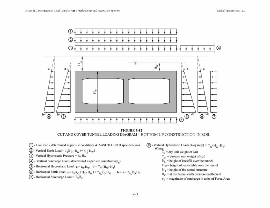
5-21
Design & Construction of Road Tunnels: Part 2 Methodology and Excavation Support Ezekiel Eneterprises, LLC
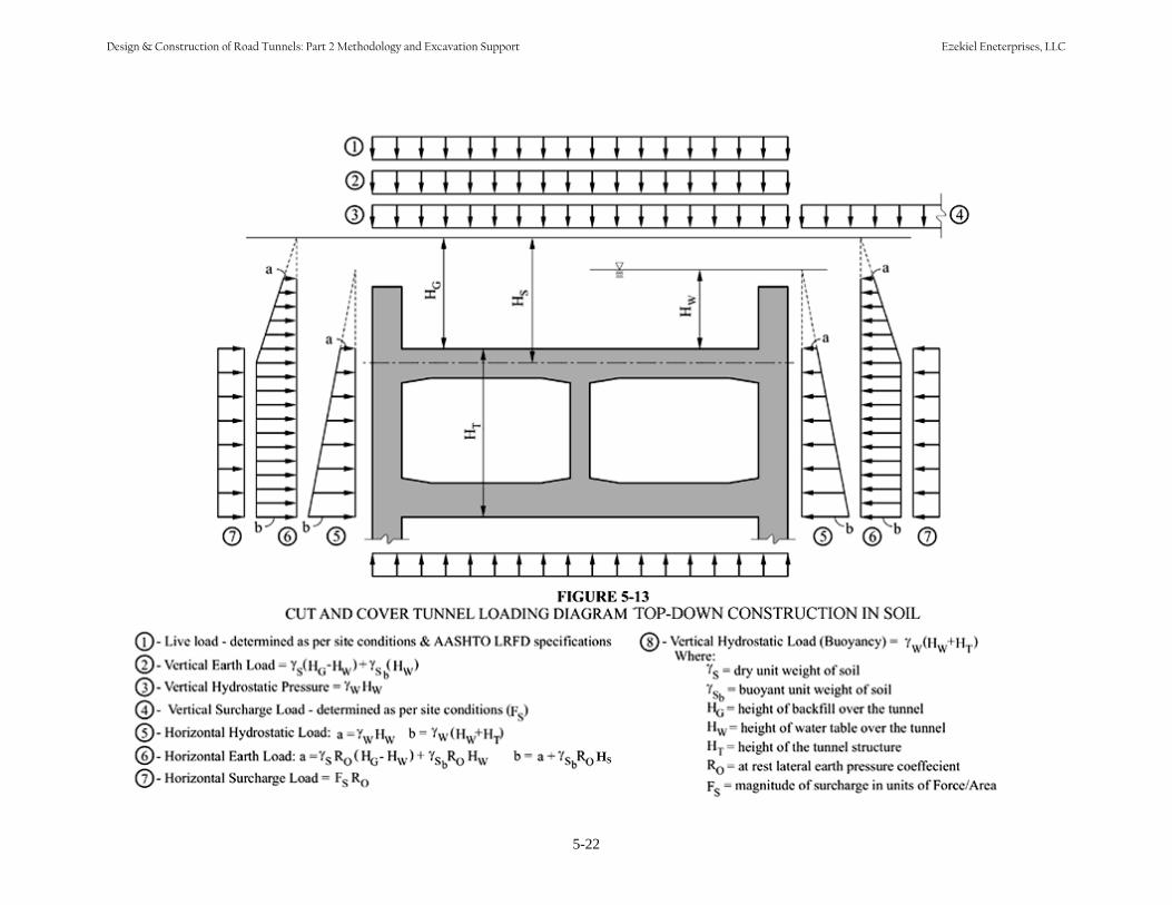
HS
5-22
Design & Construction of Road Tunnels: Part 2 Methodology and Excavation Support Ezekiel Eneterprises, LLC

load cases specified in Section 12 of the AASHTO LRFD specifications, the strength and service load cases that do not include live load should be used, specifically Strength III and Service IV. Note that load case Strength IV does not include live load. However, when using the loadings applicable to cut and cover tunnels, Strength III and Strength IV are in fact the same load cases. Combining the requirements of Section 12 and Section 3 as described above results in the following possible load combinations for use in the design of cut and cover structures:
Table 5-1 Cut and Cover Tunnel LRFD Load Combination Table
Load Comb. Limit State
DC DW EH* EV#
ES EL LL, IM
WA TU, CR, SH TG
Max Min Max Min Max Min Max Min Max Min Strength
I 1.25 0.90 1.50 0.65 1.35 0.90 1.50 0.75 1.00 1.75 1.00 1.20 0.50 0.00
Strength II 1.25 0.90 1.50 0.65 1.35 0.90 1.50 0.75 1.00 1.35 1.00 1.20 0.50 0.00
Strength III 1.25 0.90 1.50 0.65 1.35 0.90 1.50 0.75 1.00 0.00 1.00 1.20 0.50 0.00
Service I 1.00 1.00 1.00 1.00 1.00 1.00 1.00 1.20 1.00 0.50
Service IV 1.00 1.00 1.00 1.00 1.00 0.00 1.00 1.20 1.00 1.00
Service IVA** 0.00 0.90 0.90 0.90 0.00 0.00 1.00 0.00 0.00 0.00
Extreme Event I 1.25 0.90 1.50 0.65 1.35 0.90 1.50 0.75 γEQ+ 1.00 N/A N/A N/A N/A
* The load factors shown are for at-rest earth pressure. At-rest earth pressure should be used for all conditions of design of cut and cover tunnelstructures. Horizontal earth pressure is not used for Load Combination Service IVA. # The load factors shown are for rigid frames. All cut and cover tunnel structures are considered rigid frames. + This load factor is determined on a project specific basis and is not in the scope of this manual. ** This load case used to check buoyancy for tunnel structures below the permanent groundwater table. Cut and cover tunnels below the water table should be evaluated for the effect of buoyancy. This check is shown as Load Combination Service IVA in the Table 5-1. The buoyancy force should be assessed to ensure that the applied dead load effect is larger than the applied buoyancy effect. Frequently, structural member sizes will have to be increased to ensure that the buoyancy is completely resisted by the dead load or alternatively, the structure should be tied down. Calculations for buoyancy should be based on minimum characteristic material densities and maximum water density. The net effect of water pressure on the tunnel, i.e., the buoyancy, is the difference between hydrostatic loads on the roof and on the underside. The total uplift force is equal to the weight of water displaced. Friction effects (the theoretical force required to dislodge the wedge of material over the tunnel) of overlying natural materials and backfill should not be taken into account. When developing the loads to be applied to the structure, each possible combination of load factors should be developed. Engineering judgment can then be used to eliminate the combinations that will not govern. Extreme event loading is not specifically called for in the ASSHTO LRFD specification. Cut and cover tunnels, however can be subjected to extreme event loadings such as earthquakes, fires and explosions. The analysis and design for these loadings are very specialized and as such are not in the scope of this manual. However, it is recommended that during the planning phase of a tunnel, a risk analysis be
5-23
Design & Construction of Road Tunnels: Part 2 Methodology and Excavation Support Ezekiel Eneterprises, LLC
performed to identify the probability of these loads occurring, the level at which they may occur and the need for designing the tunnel to resist these loads.
5.6 STRUCTURAL DESIGN
5.6.1 General Historically there have been three basic methods used in the design of cut and cover tunnel structures: • Service load or allowable stress design which treats each load on the structure equally in terms of its
probability of occurrence at the stated value. The factor of safety for this method is built into thematerial’s ability to withstand the loading.
• Load factor design accounts for the potential variability of loads by applying varying load factors to each load type. The resistance of the maximum capacity of the structural member is reduced by astrength reduction factor and the calculated resistance of the structural member must exceed theapplied load.
• Load and resistance factor design takes into account the statistical variation of both the strength of thestructural member and of the magnitude of the applied loads.
The fundamental LRFD equation can be found in paragraph 1.3.2.1 of the AASHTO specification (AASHTO Equation 1.3.2.1-1) as follows:
ΣηiγiQi ≤ φRn = Rr 5-1
In this equation, ηi is a load modifier relating to the ductility, redundancy and operation importance of the feature being designed. The load modifier η is comprised of three components;
ηD = a factor relating to ductility = 1.0 for cut and cover tunnels constructed with conventional details and designed in accordance with the AASHTO LRFD specification.
ηR = a factor relating to redundancy = 1.0 for cut and cover tunnel design. Typical cast in place and prestressed concrete structures are sufficiently redundant to use a value of 1.0 for this factor. Typical detailing using structural steel also provides a high level of redundancy.
ηI = a factor relating to the importance of the structure = 1.05 for cut and cover tunnel design. Tunnels usually are important major links in regional transportation systems. The loss of a tunnel will usually cause major disruption to the flow of traffic, hence the higher importance factor.
γi is a load factor applied to the force effects (Qi) acting on the member being designed. Values for γ can be found in Table 5-1 above. Rr is the calculated factored resistance of the member or connection. φ is a resistance factor applied to the nominal resistance of the member (Rn) being designed. The resistance factors are given in the AASHTO LRFD specifications for each material in the section that covers the specific material. Specifically, Section 5 covers Concrete Structures and in general, the resistance factors to be used in concrete design can be found in Section 5. However, Section 12 of the AASHTO LRFD specifications gives the following values to be used for φ in Table 12.5.5-1:
5-24
Design & Construction of Road Tunnels: Part 2 Methodology and Excavation Support Ezekiel Eneterprises, LLC

For Reinforced Concrete Cast-in-Place Box Structures:
φ = 0.90 for flexure φ = 0.85 for shear
Since the walls, floors and roofs of cut and cover tunnel sections will experience axial loads, the resistance factor for compression must be defined. The value of φ for compression can be found in Section 5.5.4.2.1 of the AASHTO LRFD specifications given as:
φ = 0.75 for compression Values for φ for precast construction are also given in Table 12.5.5-1 of the AASHTO LRFD specifications, however due to size of the members involved in road tunnels, it is seldom that precast concrete will be used as a building material. Structural steel is also used in cut and cover tunnel construction. Structural steel is covered in Section 6 of the AASHTO LRFD specifications. Paragraph 6.5.4.2 gives the following values for steel resistance factors: For Structural Steel Members:
φf = 1.00 for flexure φv = 1.00 for shear φc = 0.90 for axial compression for plain steel and composite members
5.6.2 Structural Analysis
Structural analysis is covered in Section 4 of the AASHTO LRFD specifications. It is recommended that classical force and displacement methods be used in the structural analysis of cut and cover tunnel structures. Other numerical methods may be used, but will rarely yield results that vary significantly from those obtained with the classical methods. The modeling should be based on elastic behavior of the structure as per the AASHTO LRFD specifications paragraph 4.6.2.1. Since all members of a cut and cover tunnel, with the possible exception of the floor of tunnels built using top-down construction, are subjected to bending and axial load, the secondary affects of deflections on the load affects to the structural members should be accounted for in the analysis. The AASHTO LRFD specifications refer to this type of analysis as “large deflection theory” in paragraph 4.6.3.2. Most general purpose structural analysis software have provisions for including this behavior in the analysis. If this behavior is accounted for in the analysis, no further moment magnification is required. Paragraph 4.5.1 of the AASHTO LRFD specifications states that the design of the structure should include “…where appropriate, response characteristics of the foundation”. The response of the foundation for a cut and cover tunnel structure can be modeled through the use of a series of non linear springs placed along the length of the bottom slab. These springs are non linear because they should be specified to act in only one direction, the downward vertical direction. This model will provide the proper distribution of loads to the bottom slab of the model and give the designer an indication if buoyancy is a problem. This indication is seen in observing the calculated displacements of the structure. A net upward displacement of the entire structure indicates that there is insufficient resistance to buoyancy.
5-25
Design & Construction of Road Tunnels: Part 2 Methodology and Excavation Support Ezekiel Eneterprises, LLC
Structural models for computer analysis are developed using the centroid of the structural members. As such, it is important when calculating the applied loads, that the loads are calculated at the outside surface of the members. The load is then adjusted according to the actual length of the member as input. Other numerical methods of analysis for cut-and-cover tunnel sections include: • Frame analysis with a more rigorous soil-structure interaction by modeling the soil properties together
with the tunnel. The same frame analysis, but with the addition of a series of unidirectional springson the underside to model the effect of the soil as a beam on an elastic foundation. Lateral or horizontal springs may be applied in conjunction with assumed soil loads. Care must be taken toensure that the assumed soil spring acts only when deflection into the soil occurs. This may requiremultiple iterations of the input parameters for each load combination. Many commercially availableprograms will automatically adjust the input values and rerun the analysis. This gives a bettermodeling representation of the structure and takes advantage of more realistic base slab soil support,often resulting in more economical design. Setting up a model is a little more difficult with thesprings, and suitable values for the spring modulus are difficult to quantify. It may be appropriate to use a range of values and run the model for each.
• Finite element and finite difference analyses. The material of the tunnel structure and the soil are
modeled as a continuum grid of geometric elements. Structural elements are usually treated as linearelastic. A number of different mathematical models for the soil type are available. This method of modeling and analysis can more closely represent actual conditions, especially if better numerical resolution is used where there are conditions of difficult tunnel geometry such as the framing details.The method is usually complex to setup and run, and results require careful interpretation.
As stated above, two-dimensional sectional analysis is sufficient for most tunnel conditions. Three-dimensional modeling may be required where tunnel sections vary along the length of the tunnel or where intersections exist such as at ramps or cross-passages. 3-D modeling is very complex and the accuracy of the loading data, uncertainty about soil behavior, and its inherent lack of homogeneity may not warrant such detailed analysis for highway tunnels except for special locations such as ramps, cross passages, and connections to other structures.
5.7 GROUNDWATER CONTROL
5.7.1 Construction Dewatering
When groundwater levels are higher than the base level of the tunnel, excavations will require a dewatering system. For cut and cover construction, the dewatering systems will depend on the permeability of the various soil layers exposed. Lowering the water table outside the excavation could cause settlement of adjacent structures, impact on vegetations, drying of existing wells, and potential movement of contaminated plumes if present. Precautions should be taken when dewatering the area outside the excavation limits. Within the excavation, dewatering can be accomplished with impermeable excavation support walls that extend down to a firm, reasonably impermeable stratum to reduce or cut-off water flow. Impervious retaining walls, such as steel interlocking sheeting or concrete slurry walls, could be placed into deeper less pervious layers, such as glacial till or clay, to reduce groundwater inflow during construction and limit draw-down of the existing groundwater table. For most braced excavation sites,
5-26
Design & Construction of Road Tunnels: Part 2 Methodology and Excavation Support Ezekiel Eneterprises, LLC
dewatering within the excavation is often done. Sometimes the excavation is done in the wet, then the water is pumped out. Subsequent to the excavation, any water intrusion will be pumped from the trench by providing sumps and pumps within the excavation. In some areas, a pumped pressure relief system may be required to prevent the excavation bottom from heaving due to unbalanced hydrostatic pressure. Pumped wells can be used to temporarily lower the groundwater table outside the excavation support during construction; however this may have environmental impact or adverse effects on adjacent structures. To minimize any lowering of the water table immediately outside the excavation, water pumped from the excavation can be used to recharge the water bearing strata of the groundwater system by using injection wells. Provision would have to be made for disposal of water in excess of that pumped to recharge wells, probably through settlement basins draining to storm drains. After construction is completed, if there is a concerned that the permanent excavation support walls above the tunnel might be blocking the cross flow of the groundwater or may dam up water between walls above the tunnel, the designer may need to consider to breach the walls above the tunnel at intervals or removed to an elevation to allow movement of groundwater. Granular backfill around tunnels can also help to maintain equal hydrostatic heads across underground structures.
5.7.2 Methods of Dewatering and Their Typical Applications
Groundwater can be controlled during construction either by using impervious retaining walls (such as concrete slurry or tangent pile walls, steel interlocking sheeting, etc.), by well-points drawing down the water table, by chemical or grout injection into the soils, or by pumping from within the excavation. Groundwater may be lowered, as needed, by tiers of well-points. Improper control of groundwater is often a cause for settlement and damage to adjacent structures and utilities; consequently it is important that the method selected is suitable for the proposed excavation. Where the area of excavations is not too large, an economical method of collecting water is through the use of ditches leading to sump pumps. Provisions to keep fines from escaping into the dewatering system should be made. In larger excavations in permeable soil, either well points or deep wells are often used to lower the water table in sand or coarse silt deposits, but are not useful in fine silt or clay soils due to their low permeability. It is recommended that test wells be installed to test proposed systems. In certain cases, multiple stages of well points, deep wells with submersible pumps or an eductor system would be needed
5.7.3 Uplift Pressures and Mitigation Measures After construction is complete and dewatering ceases, hydrostatic uplift (buoyancy) pressures should be considered. Options that have been used to overcome this are included in Section 5.4.42.
5.7.4 Piping and Base Stability In fine-grained soils, such as silts or clayey silts, differential pressure across the support of excavation may cause sufficient water flow (piping) for it to carry fines. This causes material loss and settlement outside as well as a loss of integrity of soils within, rendering the soils unsuitable as a foundation. In extreme cases, the base of the excavation may become unstable, causing a blow-up and failure of the excavation support. This situation may be mitigated by ensuring that cut-off walls are sufficiently deep, by stabilizing the soil by grouting, or freezing, or by excavating below water without dewatering and making a sufficiently thick tremie slab to overcome uplift before dewatering.
5-27
Design & Construction of Road Tunnels: Part 2 Methodology and Excavation Support Ezekiel Eneterprises, LLC
5.7.5 Potential Impact of Area Dewatering
Dewatering an excavation may lower the groundwater outside the excavation and may cause settlements. The lowering of the external groundwater can be reduced by the use of slurry walls, tangent or secant piles, or steel sheet piling. Adjacent structures with a risk of settlement due to groundwater lowering may require underpinning. Furthermore, where lowering of groundwater exposes wooden piles to air, deterioration may occur.
5.7.6 Groundwater Discharge and Environmental Issues In most cases, the water will require testing and possibly treatment before it can be discharged. Settling basins, oil separators, and chemical treatments may be required prior to disposal. Local regulations and permitting requirements often dictate the method of disposal. The excavated material itself will require testing before the method of disposal can be determined. Material excavated below water may need to stand in settling ponds to allow excess water to run off before disposal. Contaminated material may need to be placed in confined disposal facilities.
5.8 MAINTENANCE AND PROTECTION OF TRAFFIC When the excavation crosses existing roads or is being performed under an existing road, decking would be required to maintain the existing road traffic. When decking is required the support of excavation walls must be designed to handle the imposed live loads. The depth of the walls may need to be determined by the necessity of transferring decking loads to a more competent stratum below. This may depend upon whether the load applied to the wall together with its weight can be transferred to the surrounding soil through a combination of adhesion (side friction) and end bearing. Thick types of excavation support walls, such as slurry walls, drilled-in-place soldier piles, and tangent piles, are much more effective than thinner walls, such as sheet piles or driven soldier piles, in carrying the live loads to the bearing stratum. Decking often consists of deck framing and roadway decking. Figure 5-14 depicts a typical general arrangement for street decking over a cut-and-cover excavation using timber decking. Pre-cast concrete planks have been used also as decking. Structural steel deck beams can be arranged to function also as the uppermost bracing tier of the support of excavation. The deck framing should be designed for AASHTO HL-93 loading, or for loading due to construction equipment that actually will operate on the deck, whichever is greater.
5.9 UTILITY RELOCATION AND SUPPORT
5.9.1 Types of Utilities
Constructing cut and cover tunnels in urban areas often encounters public and private utility lines such as water, sewer, power, communication, etc… Often, utilities are not located where indicated on existing utility information. Therefore, it is important to identify and locate all utilities in the field prior to excavation. Great care must be taken when excavating in the vicinity of utilities, sometimes requiring that the final excavation to expose them be done by hand. Of particular concern are those utilities that are movement-sensitive and those carrying hazardous substances; these include large diameter water pipes, high pressure gas lines, fiber optic lines, petroleum pipes and high voltage cables. Some utilities such as
5-28
Design & Construction of Road Tunnels: Part 2 Methodology and Excavation Support Ezekiel Eneterprises, LLC

buried high voltage lines are not only extremely expensive to move but have very long lead times. Utilities such as sewers can present a different problem; if gravity flow is used, diversions around a proposed tunnel may pose a serious challenge. Some older water and sewer lines are extremely fragile, particularly if they are of brick or cast iron construction.
Figure 5-14 Typical Street Decking (After Bickel et al., 1996)
5-29
Design & Construction of Road Tunnels: Part 2 Methodology and Excavation Support Ezekiel Eneterprises, LLC
5.9.2 General Approach to Utilities during Construction
It is not uncommon to divert utilities away from the proposed construction corridor. However, diversion is not always possible, it may be too expensive, or a utility crossing may be unavoidable; in such cases, it will be necessary to support the utilities in place. It is essential to have a coordinated effort so that no interferences among the various utilities occurs and that the construction can be done while the utilities are in place. Sometimes, utility relocations are done in stages to accommodate the construction requiring relocating the utility more than once. Before the start of underground construction, a condition survey should be made of all utilities within the zone of potential influence of construction, making detailed reports for those that may incur movements in excess of those allowable for the utility. The nature of any work required for each utility should be identified, i.e., protection, support or relocation, and the date by which action is required. It is essential that all utilities that need action are identified in sufficient time to allow the construction to progress as programmed. Supports may either be temporary or permanent. Depending upon the sensitivity of the utility being supported, it may be necessary to provide instrumentation to monitor any movement so that remedial action can be taken before damage occurs. Systems providing vertical support should be designed as bridge structures. Lateral support may be considered as retaining walls. Most utilities require access for repairs; it is therefore required to have provisions for access to utilities passing beneath a tunnel. In some cases, it has been found appropriate to relocate utilities to a trough or utility tunnel in which all utilities can be easily accessed. In some cases, utilities cannot be raised sufficiently to clear the tunnel roof slab; it may be possible to create a narrow trough across the roof in which the utility may be relocated. In certain situations, utilities were passed through the tunnel by providing a special conduit below the tunnel roof. In all cases, all utility work must be carefully coordinated with the utility owner.
5-30
Design & Construction of Road Tunnels: Part 2 Methodology and Excavation Support Ezekiel Eneterprises, LLC
CHAPTER 6
ROCK TUNNELING
6.1 INTRODUCTION Chapters 6 through 10 present design recommendations and requirements for mined and bored road tunnels in all types of grounds. Chapter 6 addresses analysis, design and construction issues for rock tunneling including rock failure mechanism, rock mass classification, excavation methods, excavation supports, and design considerations for permanent lining, groundwater control, and other ground control measures. Chapter 10 addresses the design of various types of permanent lining applicable for rock tunnels. Because of the range of behavior of tunnels in rock, i.e., from a coherent continuum to a discontinuum, stabilization measures range from no support to bolts to steel sets to heavily reinforced concrete lining and numerous variations and combinations in between. Certainly these variations are to be expected when going from one tunnel to another but often several are required in a single tunnel because the geology and/or the geometry change. Thus, the engineer must recognize the need for change and prepare the design to allow for adjustments to be made in the field to adjust construction means, methods, and equipment to the challenges presented by the vagaries of nature. This chapter provides the engineer with the basic tools to approach the design, it is not a cookbook that attempts to give instantaneous solutions/designs for the novice designer. The data needed for analysis and design rock tunnels and the investigative techniques to obtain the data are discussed in Chapter 3. The results of the analysis and design presented hereafter are typically presented in the geotechnical/technical design memorandum (Chapter 4) and form the basis of the Geotechnical Baseline Report (Chapter 4). Readers are referred to Chapter 7 for tunneling issues in soft ground. Problematic ground condition such as running sand and very soft clays are discussed in Chapter 8. Mining sequentially based on the sequential excavation method (SEM) principles is discussed in Chapter 9. 6.2 ROCK FAILURE MECHANISM Only in the last half-century has rock mechanics evolved into a discipline of its own rather than being a sub-set of soil mechanics. At the same time there was a “merging of elastic theory, which dominated the English language literature on the subject, with the discontinuum approach of the Europeans” (Hoek, 2000). These two phenomena have also occurred during a time of ever-increasing demand for economical tunnels. Hence, design and construction of rock tunnels have taken on a new impetus and importance in the overall field of heavy construction as it applies to infrastructure. Understanding the failure mechanism of a rock mass surrounding an underground opening is essential in the design of support systems for the openings. The failure mechanism depends on the in situ stress level and characteristics of the given rock mass. At shallow depths, where the rock mass is blocky and jointed, the stability problems are generally associated with gravity falls of wedges from the roof and sidewalls since the rock confinement is generally low. As the depth below the ground surface increases, the rock stress increases and may reach a level at which the failure of the rock mass is induced. This rock mass failure can include spalling, slabbing, and major rock burst. Conversely, excavation of an underground opening in an unweathered massive rock mass may be the most ideal condition. When this condition, paired together with relatively low stresses, exists, the
6-1
Design & Construction of Road Tunnels: Part 2 Methodology and Excavation Support Ezekiel Eneterprises, LLC
excavation will usually not suffer from serious stability problems, thus support requirement will be minimal. 6.2.1 Wedge Failure Due to the size of tunnel openings (relative to the rock joint spacing) in most infrastructure applications, the rock around the tunnel tends to act more like a discontinuum. Behavior of a tunnel in a continuous material depends on the intrinsic strength and deformation properties of that material whereas behavior of a tunnel in a discontinuous material depends on the character and spacing of the discontinuities. Design of the former lends itself more naturally to analytical modeling (similar to most tunnels in soil) whereas design of the latter requires consideration of possible block or wedge movement or failure wherein the design approach is to hold the rock mass together. By doing so, the rock is forced to form a “ground arch” around the opening and hence to redistribute the forces such that the ground itself carries most of the “load”. To stabilize blocks or wedges, and hence the opening, the first step is to determine the number, orientations and conditions of the joints. The Q system, described in 6.3.4 gives the basic information required for the joint sets: • Number of joints• Joint roughness• Joint alteration• Joint water condition• Joint stress condition With these parameters defined, analyses can be made of the block or wedge stability and of the support required to increase that stability to a satisfactory level. For small tunnels of ordinary geometry the initial analysis (if not the final) can be estimated from a simple free-body approach. For larger tunnels with complicated geometry and/or a more complicated joint system, it is recommended that a computer program such as Unwedge be used to analyze the opening. Once the basic parameters of the problem are input to the program, a series of runs can be made to evaluate the impact of such variations on the calculated support required for the opening. A design practice using Unwedge will be introduced in Section 6.6.2. As indicated earlier, except for a small tunnel in very massive rock, the concept of “solid rock” is usually a misconception. As a result, the behavior of the ground around a rock tunnel is usually the combination of that of a blocky medium and a continuum. Hence, the “loads” on the tunnel support system are usually erratic and nonuniform. This is in contrast to soft ground tunnels where the ground may sometimes be approximated by elastic or elastic-plastic assumptions or where the parameters going into numerical modeling are significantly more amenable to rational approximations. In its simplest terms the challenge to supporting a tunnel in rock is to prevent the natural tendency of the rock to “unravel”. Most failures in rock tunnels are initiated by a block (called “keyblocks” by Goodman, 1980) that wants to loosen and come out. When that block succeeds, others tend to loosen and follow. This can continue until the tunnel completely collapses or until the geometry and stress conditions come to equilibrium and the unraveling stops. Contrarily, if that first block can be held in place the stresses rearrange themselves into the ground arch around the tunnel and stability is attained. Figure 6-1 illustrates how detrimental blocky behavior propagates while Figure 6-2 shows how holding the key block in place can stabilize the opening (After Deere 1969).
6-2
Design & Construction of Road Tunnels: Part 2 Methodology and Excavation Support Ezekiel Eneterprises, LLC
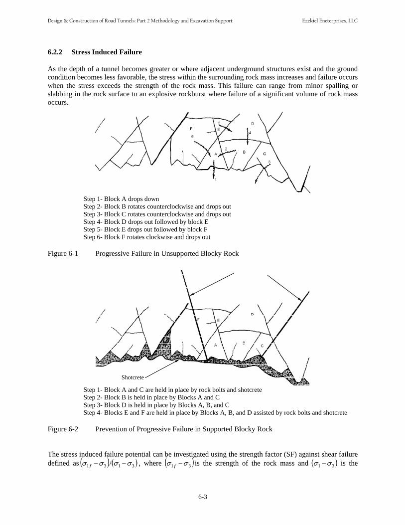
6.2.2 Stress Induced Failure
As the depth of a tunnel becomes greater or where adjacent underground structures exist and the ground condition becomes less favorable, the stress within the surrounding rock mass increases and failure occurs when the stress exceeds the strength of the rock mass. This failure can range from minor spalling or slabbing in the rock surface to an explosive rockburst where failure of a significant volume of rock mass occurs.
F
C
Step 1- Block A drops down Step 2- Block B rotates counterclockwise and drops out Step 3- Block C rotates counterclockwise and drops out Step 4- Block D drops out followed by block E Step 5- Block E drops out followed by block F Step 6- Block F rotates clockwise and drops out
Figure 6-1 Progressive Failure in Unsupported Blocky Rock
Shotcrete
Rock Bolts
Step 1- Block A and C are held in place by rock bolts and shotcrete Step 2- Block B is held in place by Blocks A and C Step 3- Block D is held in place by Blocks A, B, and C Step 4- Blocks E and F are held in place by Blocks A, B, and D assisted by rock bolts and shotcrete
Figure 6-2 Prevention of Progressive Failure in Supported Blocky Rock
The stress induced failure potential can be investigated using the strength factor (SF) against shear failuredefined as (σ 1 f −σ 3 )/(σ 1 −σ3 ) , where (σ 1 f −σ3 ) is the strength of the rock mass and (σ 1 −σ3 ) is the
6-3
Design & Construction of Road Tunnels: Part 2 Methodology and Excavation Support Ezekiel Eneterprises, LLC

induced stress, σ1 and σ3 are major and minor principal stresses, and σ1f is major principal stress at failure. A SF greater than 1.0 indicates that the rock mass strength is greater than the induced stress, i.e., there is no overstress in the rock mass. When SF is less than 1.0, the induced stresses are greater than the rock mass strength, and the rock mass is overstressed and likely to behave in the plastic range.
6.2.3 Squeezing and Swelling
Squeezing rock is associated with the creation of a plastic region around an opening and severe face instability. From a tunnel design point of view, a rock mass is considered to be weak when its in-situ uniaxial compressive strength is significantly lower than the natural and excavation induced stresses acting upon the rock mass surrounding a tunnel. Hoek et. al. (2000) proposed a chart to predict squeezing problems based on strains with no support system as shown in Figure 6-3. As a very approximate and simple estimation, Figure 6-3 can be directly used to predict squeezing potential by comparing rock mass strength and in-situ stress. If finite element analysis results are available, one can simply predict the squeezing potential based on the calculated strains from the FE analysis. For example, the squeezing problems, if a tunnel is excavated at the proposed depth, are severe when the calculated strains from FE analysis is 2.5% or higher. It should be noted that strains in Figure 6-3 are based on tunnels with no support installed.
Figure 6-3 A Relationship between Strain and Squeezing Potential of Rock Mass (Hoek, et. al., 2000)
Swelling rock, in comparison, is associated with an increase in moisture content of the rock. Swelling rock can sometimes be associated with squeezing rock, but may occur without formation of a plastic zone. The swelling is usually associated with clay minerals, indurated to shale or slate or not, imbibing water and expanding. A relatively simple swell test in the laboratory will allow prediction of the swell and will
6-4
Design & Construction of Road Tunnels: Part 2 Methodology and Excavation Support Ezekiel Eneterprises, LLC

also provide the “swelling pressure”, where the swelling pressure is defined as that pressure that must be applied to the rock to arrest the swelling. Obviously, the support system has to resist at least the full swelling pressure to arrest the swelling movement. Montmorillinitic shales, weathered nontronite basalts, and some salts found in evaporate deposits are typical swelling rocks. Chapter 8 provides more detailed discussions about problematic squeezing and swelling ground. 6.3 ROCK MASS CLASSIFICATIONS 6.3.1 Introduction Rock mass classification schemes have been developed to assist in (primarily) the collection of rock into common or similar groups. The first truly organized system was proposed by Dr. Karl Terzaghi (1946) and has been followed by a number of schemes proposed by others. Terzaghi’s system was mainly qualitative and others are more quantitative in nature. The following subsections explain three systems and show how they can be used to begin to develop and apply numerical ratings to the selection of rock tunnel support and lining. This section discusses various rock mass classification systems mainly used for rock tunnel design and construction projects. 6.3.2 Terzaghi’s Classification Today rock tunnels are usually designed considering the interaction between rock and ground, i.e., the redistribution of stresses into the rock by forming the rock arch. However, the concept of loads still exists and may be applied early in a design to “get a handle” on the support requirement. The concept is to provide support for a height of rock (rock load) that tends to drop out of the roof of the tunnel (Terzaghi, 1946). Terzaghi’s qualitative descriptions of rock classes are summarized in Table 6-1.
Table 6-1 Terzaghi’s Rock Mass Classification
Rock Condition Descriptions Intact rock Contains neither joints nor hair cracks. Hence, if it breaks, it breaks
across sound rock. On account of the injury to the rock due to blasting, spalls may drop off the roof several hours or days after blasting. This is known as a spalling condition. Hard, intact rock may also be encountered in the popping condition involving the spontaneous and violent detachment of rock slabs from the sides or roof
Stratified rock Consists of individual strata with little or no resistance against separation along the boundaries between the strata. The strata may or
may not be weakened by transverse joints. In such rock the spalling condition is quite common
Moderately jointed rock Contains joints and hair cracks, but the blocks between joints are locally grown together or so intimately interlocked that vertical walls do not
require lateral support. In rocks of this type, both spalling and popping conditions may be encountered
Blocky and seamy rock Consists of chemically intact or almost intact rock fragments which are entirely separated from each other and imperfectly interlocked. In such rock, vertical walls may require lateral support
Continued on next page
6-5
Design & Construction of Road Tunnels: Part 2 Methodology and Excavation Support Ezekiel Eneterprises, LLC
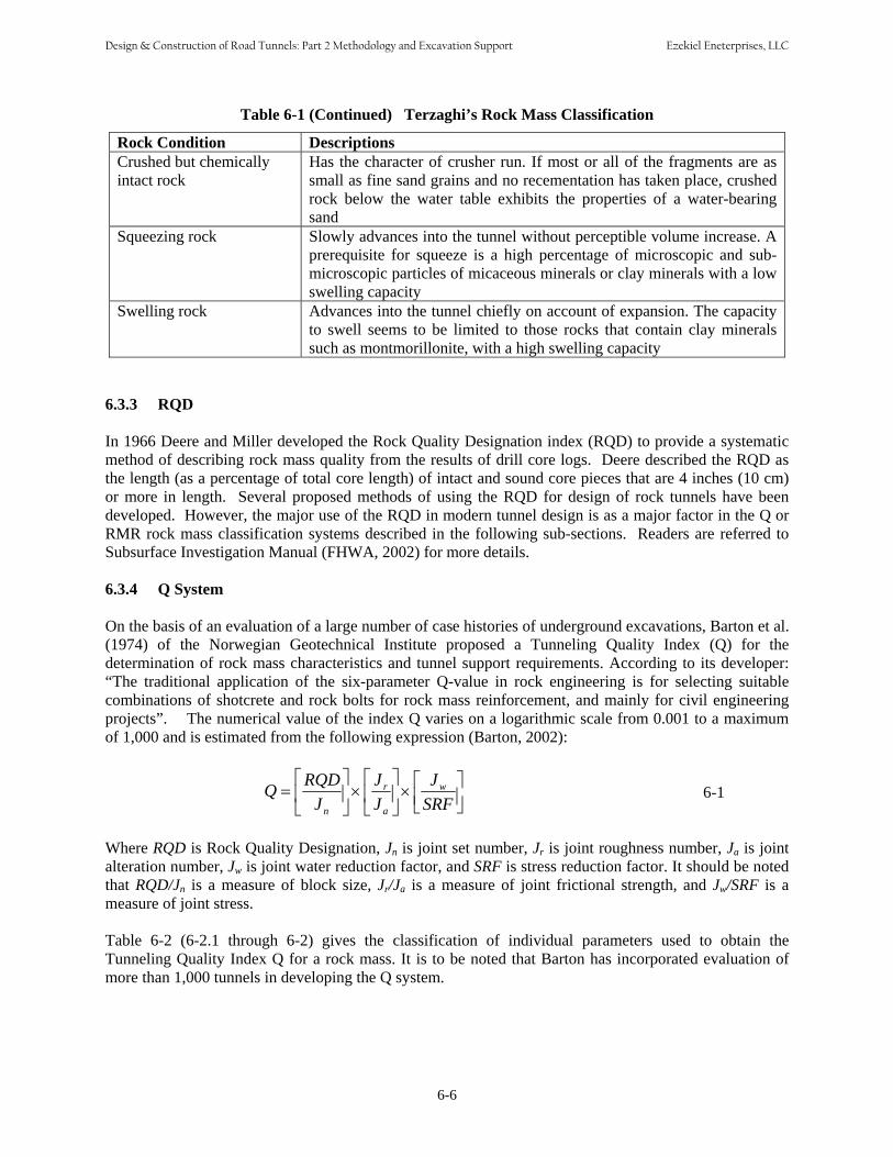
Table 6-1 (Continued) Terzaghi’s Rock Mass Classification
Rock Condition Descriptions Crushed but chemically Has the character of crusher run. If most or all of the fragments are as
intact rock small as fine sand grains and no recementation has taken place, crushed rock below the water table exhibits the properties of a water-bearing sand
Squeezing rock Slowly advances into the tunnel without perceptible volume increase. A prerequisite for squeeze is a high percentage of microscopic and sub
microscopic particles of micaceous minerals or clay minerals with a low swelling capacity
Swelling rock Advances into the tunnel chiefly on account of expansion. The capacity to swell seems to be limited to those rocks that contain clay minerals
such as montmorillonite, with a high swelling capacity
⎡ RQD ⎤ ⎡ J ⎤ ⎡ J ⎤Q = ⎢ ⎥ × ⎢
r ⎥ ×
w ⎢ ⎥ 6-1⎣ J n ⎦ ⎣ J a ⎦ ⎣ SRF ⎦
6.3.3 RQD
In 1966 Deere and Miller developed the Rock Quality Designation index (RQD) to provide a systematic method of describing rock mass quality from the results of drill core logs. Deere described the RQD as the length (as a percentage of total core length) of intact and sound core pieces that are 4 inches (10 cm) or more in length. Several proposed methods of using the RQD for design of rock tunnels have been developed. However, the major use of the RQD in modern tunnel design is as a major factor in the Q or RMR rock mass classification systems described in the following sub-sections. Readers are referred to Subsurface Investigation Manual (FHWA, 2002) for more details.
6.3.4 Q System
On the basis of an evaluation of a large number of case histories of underground excavations, Barton et al. (1974) of the Norwegian Geotechnical Institute proposed a Tunneling Quality Index (Q) for the determination of rock mass characteristics and tunnel support requirements. According to its developer: “The traditional application of the six-parameter Q-value in rock engineering is for selecting suitable combinations of shotcrete and rock bolts for rock mass reinforcement, and mainly for civil engineering projects”. The numerical value of the index Q varies on a logarithmic scale from 0.001 to a maximum of 1,000 and is estimated from the following expression (Barton, 2002):
Where RQD is Rock Quality Designation, Jn is joint set number, Jr is joint roughness number, Ja is joint alteration number, Jw is joint water reduction factor, and SRF is stress reduction factor. It should be noted that RQD/Jn is a measure of block size, Jr/Ja is a measure of joint frictional strength, and Jw/SRF is a measure of joint stress. Table 6-2 (6-2.1 through 6-2) gives the classification of individual parameters used to obtain the Tunneling Quality Index Q for a rock mass. It is to be noted that Barton has incorporated evaluation of more than 1,000 tunnels in developing the Q system.
6-6
Design & Construction of Road Tunnels: Part 2 Methodology and Excavation Support Ezekiel Eneterprises, LLC

Table 6-2 Classification of Individual Parameters for Q System (after Barton et al, 1974)
6-7
Design & Construction of Road Tunnels: Part 2 Methodology and Excavation Support Ezekiel Eneterprises, LLC
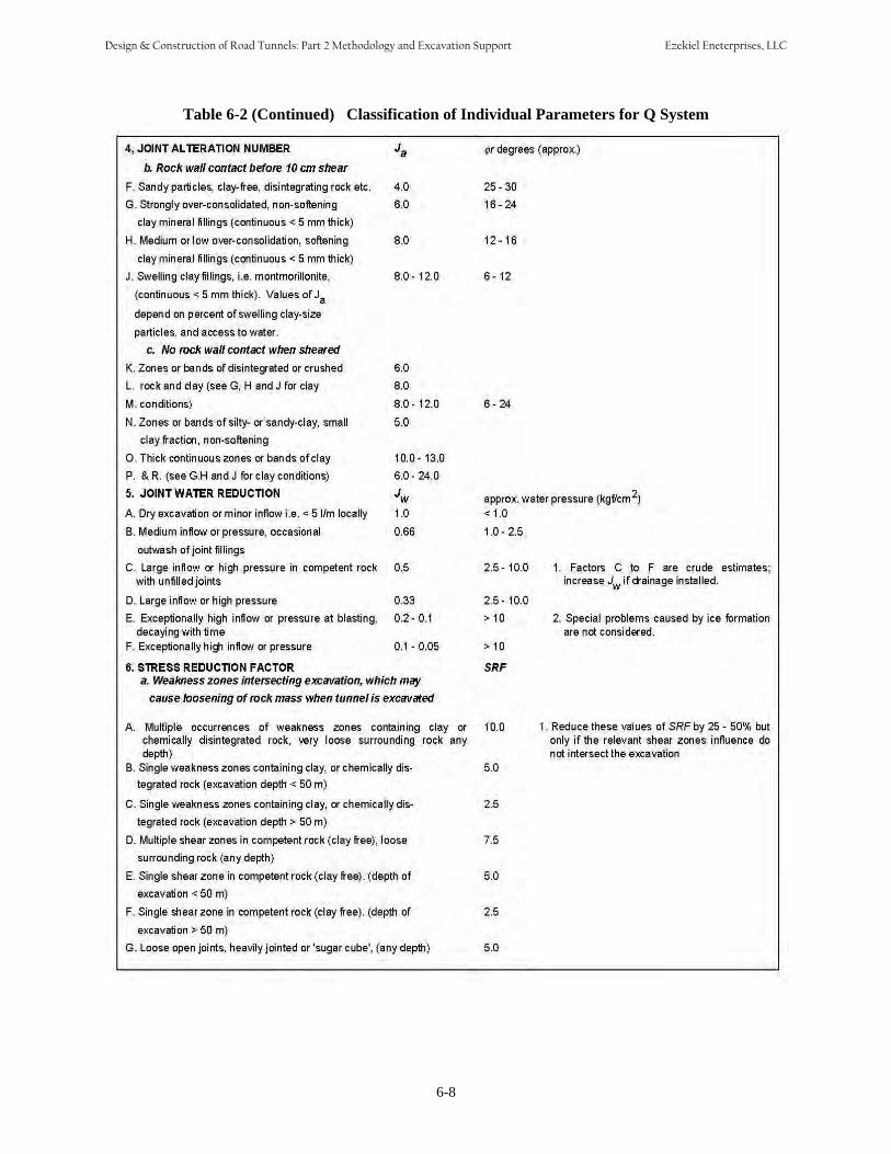
Table 6-2 (Continued) Classification of Individual Parameters for Q System
6-8
Design & Construction of Road Tunnels: Part 2 Methodology and Excavation Support Ezekiel Eneterprises, LLC

Table 6-2 (Continued) Classification of Individual Parameters for Q System
Evaluation of these Q-parameters and the use of Table 6-2 can be illustrated considering a reach of tunnel with the following properties:
Parameter Description Value Table RQD 75 to 90 RQD = 80 6-2.1Joint Sets Two joint sets plus random joints Jn = 6 6-2.2Joint roughness Smooth, undulating Jr = 2 6-2.3
Joint alteration Slightly altered joint walls, non-softening mineral coatings, sandy particles, clay-free disintegrated rock, etc. Ja = 2 6-2.4
Joint water reduction factor Medium inflow with occasional outwash of joint fillings Jw = 0.66 6-2.5
Stress reduction factor Medium stress, favorable stress condition SRF = 1.0 6-2.6
6-9
Design & Construction of Road Tunnels: Part 2 Methodology and Excavation Support Ezekiel Eneterprises, LLC

With the parameters established, Q is calculated:
⎡ RQD ⎤ ⎡ Jr ⎤ ⎡ J ⎤ 80 2 0.66Q = ⎢ ⎥ × ⎢ ⎥ × w = ⎥ × × =⎢ 9 ⎣ Jn ⎦ ⎣ Ja ⎦ ⎣ SRF ⎦ 6 2 1
Refer to Figure 6-25 for guidance in using Q to select excavation support. It should be noted, however, that “the Q-system has its best applications in jointed rock mass where instability is caused by rock falls. For most other types of ground behavior in tunnels, the Q-system, like most other empirical (classification) methods has limitations. The Q support chart gives an indication of the support to be applied, and it should be tempered by sound and practical engineering judgment” (Palmstream and Broch, 2006). The Q-system was developed from over 1000 tunnel projects, most of which are in Scandinavia and all of which were excavated by drill and blast methods. When excavation is by TBM there is considerably less disturbance to the rock than there is with drill and blast. Based upon study of a much smaller data base (Barton, 1991) it is recommended that the Q for TBM excavation be increased by a factor of 2 for Qs between 4 and 30.
6.3.5 Rock Mass Rating (RMR) System
Z.T. Bieniawski (1989) has developed the Rock Mass Rating (RMR) system somewhat along the same lines as the Q system. The RMR uses six parameters, as follows:
• Uniaxial compressive strength of rock• RQD• Spacing of discontinuities• Condition of discontinuities• Groundwater condition• Orientation of discontinuities
The ratings for each of these parameters are obtained from Table 6-3. The sum of the six parameters becomes the basic RMR value as demonstrated in the following example. Table 6-9 presents how the RMR can be applied to determining support requirements for a tunnel with a 33 ft (10 m) width span. Determination of the RMR value using Table 6-3 can be demonstrated in the following example:
Parameter Description Table6-3
Value
Rock Strength 20,000 psi = 138 MPa A1 12
RQD 75 to 90 A2 17
Spacing of Discontinuities 4 ft –- 1.2M A3 15
Condition of Discontinuities Slightly rough, slightly weathered
A4 25
Groundwater Dripping A5 4
Discontinuity Orientation Fair B -5
Total Rating Class II, Good Rock C 68
6-10
Design & Construction of Road Tunnels: Part 2 Methodology and Excavation Support Ezekiel Eneterprises, LLC
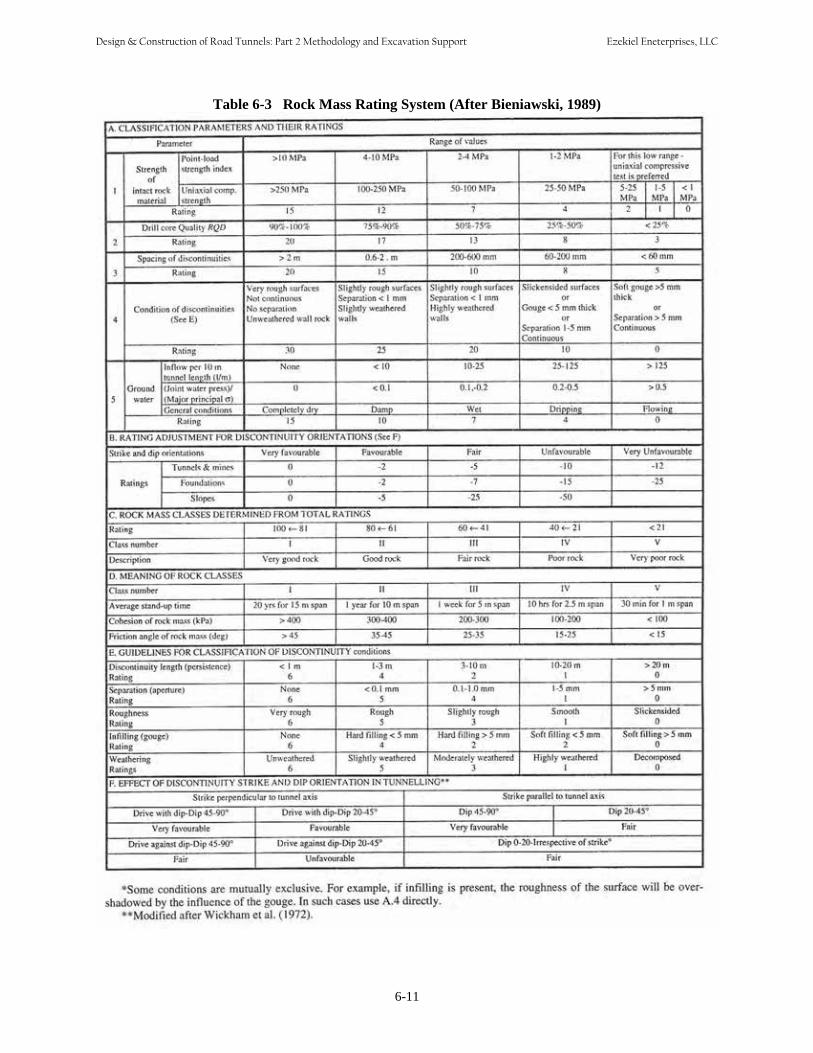
Table 6-3 Rock Mass Rating System (After Bieniawski, 1989)
6-11
Design & Construction of Road Tunnels: Part 2 Methodology and Excavation Support Ezekiel Eneterprises, LLC
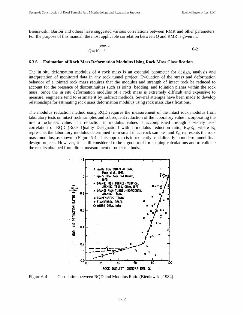
Bieniawski, Barton and others have suggested various correlations between RMR and other parameters. For the purpose of this manual, the most applicable correlation between Q and RMR is given in:
RMR−50 15 6-2Q = 10
6.3.6 Estimation of Rock Mass Deformation Modulus Using Rock Mass Classification
The in situ deformation modulus of a rock mass is an essential parameter for design, analysis and interpretation of monitored data in any rock tunnel project. Evaluation of the stress and deformation behavior of a jointed rock mass requires that the modulus and strength of intact rock be reduced to account for the presence of discontinuities such as joints, bedding, and foliation planes within the rock mass. Since the in situ deformation modulus of a rock mass is extremely difficult and expensive to measure, engineers tend to estimate it by indirect methods. Several attempts have been made to develop relationships for estimating rock mass deformation modulus using rock mass classifications.
The modulus reduction method using RQD requires the measurement of the intact rock modulus from laboratory tests on intact rock samples and subsequent reduction of the laboratory value incorporating the in-situ rockmass value. The reduction in modulus values is accomplished through a widely used correlation of RQD (Rock Quality Designation) with a modulus reduction ratio, EM/EL, where EL represents the laboratory modulus determined from small intact rock samples and EM represents the rock mass modulus, as shown in Figure 6-4. This approach is infrequently used directly in modern tunnel final design projects. However, it is still considered to be a good tool for scoping calculations and to validate the results obtained from direct measurement or other methods.
Figure 6-4 Correlation between RQD and Modulus Ratio (Bieniawski, 1984)
6-12
Design & Construction of Road Tunnels: Part 2 Methodology and Excavation Support Ezekiel Eneterprises, LLC

Based on the back analyses of a number of case histories, several methods have been propounded to evaluate the in situ rock mass deformation modulus based on rock mass classification. The methods are summarized in Table 6-4.
Table 6-4 Estimation of Rock Mass Deformation Modulus Using Rock Mass Classification
Rock Mass Deformation Modulus (MPa) Reference
( ) 40
10
10 −
= RMR
mE Serafim and Pereira (1983)
Log QEm 10 = 25 Barton et. al. (1980, 1992), Grimstad and Barton (1993)
⎟⎠⎞
⎜⎝⎛ −
⋅= 40 10
10 100
GSI ci
mE σ * Hoek and Brown (1998)
( )( ) ⎥⎦⎤
⎢⎣ ⎡ +
− = −+ /1125751
/ 21100000 GSIDm e DE ** Hoek and Diederichs (2006)
1002 −= RMREm for RMR ≥ 50 Bieniawski (1978)
( )[ ] GPaERMRRMREE iim 50/ 22.82 ,0.9exp/100 0.0028 2 =+= Nicholson and Bieniawski (1990)
( /10)30.1 RMREm = Read et. al. (1999)
* GSI represents Geological Strength Index. The value of GSI ranges from 10, for extremely po or rock mass, to 100 for intactrock. (GSI = RMR76 = RMR89 – 5 = 9LogeQ + 44)** D is a factor which depends upon the degree of disturbance due to blast damage and stress relaxation. It varies from 0 forundisturbed in situ rock masses to 1 for very disturbed rock masses. Guidelines for the selection of D are presented in Table 6-5. 6.4 ROCK TUNNELING METHODS 6.4.1 Drill and Blast When mankind first started excavating underground, the choices of tools were extremely limited – bones, antlers, wood and rocks, along with a lot of muscle power. Exactly when and where black powder was first used has been lost in history but it is generally agreed that progress was quite slow until the early 1800’s. Then, in the mid 1800’s, Alfred Nobel invented dynamite and we began to make significant progress in excavations for mining, civil, and military applications. For the reader who wants to pursue this interesting topic, see Hemphill (1981). Modern drill and blast excavation for civil projects is still very much related to mining and is a mixture of art and science. The basic approach is to drill a pattern of small holes, load them with explosives, and then detonate those explosives thereby creating an opening in the rock. The blasted and broken rock (muck) is then removed and the rock surface is supported so that the whole process can be repeated as many times as necessary to advance the desired opening in the rock.
6-13
Design & Construction of Road Tunnels: Part 2 Methodology and Excavation Support Ezekiel Eneterprises, LLC

Table 6-5 Estimation of Disturbance Factor, D
Appearance Description of Rock Mass Suggested Value
Excellent quality controlled blasting or excavation by Tunnel Boring Machine results in minimal disturbance to the confined rock mass surrounding a tunnel.
D = 0
Mechanical or hand excavation in poor quality rock masses (no blasting results in minimal disturbance to the surrounding rock mass.
Where squeezing problems result in significant floor heave, disturbance can be severe unless a temporary invert, as shown in the paragraph, is placed.
D = 0
D = 0.5 No invert
Very poor quality blasting in a hard rock tunnel results in severe local damage, extending 2 or 3m, in the surrounding rock mass. D = 0.8
Small scale blasting in civil engineering slopes results in modest rock mass damage, particularly if controlled blasting is used as shown on the left hand side of the paragraph. However, stress relief results in some disturbance.
D = 0.7 Good blasting
D = 1.0 Poor blasting
Very large open pit mine slopes suffer significant disturbance due to heavy production blasting and also due to stress relief from overburden removal.
In some softer rocks excavation can be carried out by ripping and dozing and he degree of damage to the slope is less
D = 1.0 Production blasting
D = 0.7 Mechanical excavation
By its very nature this process leaves a rock surface fractured and disturbed. The disturbance typically extends one to two meters into the rock and can be the initiator of a wedge failure as discussed previously. As a minimum this usually results in an opening larger than needed for its service requirement and in the need to install more supports than would be needed if the opening could be made with fewer disturbances. To reduce the disturbance “Controlled Blasting” technique as discussed in Section 6.4.1.1 can be applied. 6.4.1.1 Controlled Blasting Principles Explosives work by a rapid chemical reaction that results in a hot gas with much larger volume than that occupied by the explosive. This is possible because the explosive contains both the fuel and the oxidizer. When the explosive detonates, the rapidly expanding gas performs two functions: applying a sharp impulse to the borehole wall (which fractures the rock) and permeating the new fractures and existing discontinuities (which pries the fragments apart). To deliver this one-two punch effectively, the explosive is distributed through the rock mass, by drilling an array of boreholes that are then loaded with explosives and fired in an orderly sequence.
6-14
Design & Construction of Road Tunnels: Part 2 Methodology and Excavation Support Ezekiel Eneterprises, LLC

6.4.1.2 Relief
In order to effectively fragment the rock, there must be space for the newly created fragments to move into. If there is not, the rock is fractured but not fragmented, and this unstable mass will remain in place. Therefore the geometry of the array of boreholes must be designed to allow the fragments to move. This is optimum if there is more than one free face available. Creating an artificial “free face” is discussed in Section 6.4.1.5.
6.4.1.3 Delay Sequencing
To optimize the relief, internal free faces must be created during the blast sequence. To do this, millisecond delay detonators separate the firing times of the charges by very short lengths of time. Historically, because of scatter in the firing times of pyrotechnic detonators, “long” period delays between holes (on the order of hundreds of milliseconds) have been used in tunnel and underground mining, resulting in blasts that last several seconds. This is changing as more accurate electronic detonators are developed.
6.4.1.4 Tunnel Blast Specifics
As mentioned, tunnel blasting (like underground mine blasting) differs from surface blasting in that there is usually only one free face that provides relief. To blast some large tunnels, an upper heading is blasted first, and the rest of the rock is taken with a bench blast. Often, though, the whole face is drilled and blasted in one event. An array of blastholes is drilled out using drilling equipment that can drill several holes at once. The pattern of drill holes is determined before the blast, taking into account the rock type, the existing discontinuities in the rock (joints, fractures, bedding planes), and of course the desired final shape of the tunnel. Figure 6-5 shows a rather simplified example of a full-face tunnel round, with the various types of holes. The sequence of firings is Burn Cut (the holes in the neighborhood of the Open Cut Holes shown in the diagram), Production Holes (the holes in the “Blasthole Slash Area”), and the Smoothwall Holes (at the perimeter of the round).
Figure 6-5 Example of a Full-face Tunnel Blast
6-15
Design & Construction of Road Tunnels: Part 2 Methodology and Excavation Support Ezekiel Eneterprises, LLC
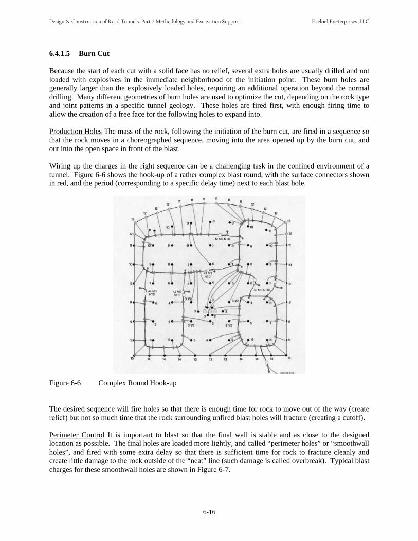
6.4.1.5 Burn Cut
Because the start of each cut with a solid face has no relief, several extra holes are usually drilled and not loaded with explosives in the immediate neighborhood of the initiation point. These burn holes are generally larger than the explosively loaded holes, requiring an additional operation beyond the normal drilling. Many different geometries of burn holes are used to optimize the cut, depending on the rock type and joint patterns in a specific tunnel geology. These holes are fired first, with enough firing time to allow the creation of a free face for the following holes to expand into.
Production Holes The mass of the rock, following the initiation of the burn cut, are fired in a sequence so that the rock moves in a choreographed sequence, moving into the area opened up by the burn cut, and out into the open space in front of the blast.
Wiring up the charges in the right sequence can be a challenging task in the confined environment of a tunnel. Figure 6-6 shows the hook-up of a rather complex blast round, with the surface connectors shown in red, and the period (corresponding to a specific delay time) next to each blast hole.
Figure 6-6 Complex Round Hook-up
The desired sequence will fire holes so that there is enough time for rock to move out of the way (create relief) but not so much time that the rock surrounding unfired blast holes will fracture (creating a cutoff). Perimeter Control It is important to blast so that the final wall is stable and as close to the designed location as possible. The final holes are loaded more lightly, and called “perimeter holes” or “smoothwall holes”, and fired with some extra delay so that there is sufficient time for rock to fracture cleanly and create little damage to the rock outside of the “neat” line (such damage is called overbreak). Typical blast charges for these smoothwall holes are shown in Figure 6-7.
6-16
Design & Construction of Road Tunnels: Part 2 Methodology and Excavation Support Ezekiel Eneterprises, LLC

Figure 6-7 Typical Blast Charges
Though fired after the Production Holes have been detonated, the Smoothwall Holes are often fired on the same delay period, creating a “zipper” effect of the holes generating a smooth fracture on the perimeter. Environmental Effects – Vibration and Airblast Not all of the energy from blasting goes into fragmenting rocks – some of it is unavoidably wasted as vibration that propagates away from the blast area. This vibration can be cause for concern both for the stability of the tunnel itself, as well as neighboring underground and surface structures. Airblast is an air pressure wave that propagates away from the blast site, due to movement of the rock face and also possible venting of explosive gases from the boreholes. This is not so much a problem in tunneling, where personnel are evacuated from the blast area before a blast, but still must be taken into account. Both of these issues are covered in more detail in Chapter 15, Instrumentation. 6.4.1.6 Blasting – Art vs. Science As mentioned earlier, explosives have been used for a long time to excavate rock. With the passage of time, engineers have studied the scientific relationships between the properties of explosives, the controllable variables such as the geometry of a blast and the timing, and uncontrollable variables such as variations in rock type and existing jointing and fracturing. Many relationships can show the most appropriate configuration of the blastholes, timing, and explosive type. However, as can be seen from the Figure 6-8 of actual drilling for a tunnel blast, the ideal is difficult to achieve. Holes are marked out with spray paint on an irregular surface, and drilled in a dirty, often wet environment. The roof is supported with rock bolts (shown by the red squares in Figure 6-8) and meshes. Lighting is limited. Overall, this makes for a very challenging work environment. Experience, or the “art” of blasting, comes into play in implementing the desired blast design. Choice of an experienced and capable blasting contractor, as well as a blast consultant to advise the contractor, is important to obtain the desired results.
6-17
Design & Construction of Road Tunnels: Part 2 Methodology and Excavation Support Ezekiel Eneterprises, LLC
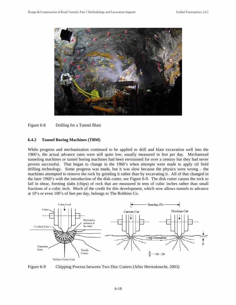
Figure 6-8 Drilling for a Tunnel Blast
6.4.2 Tunnel Boring Machines (TBM)
While progress and mechanization continued to be applied to drill and blast excavation well into the 1960’s, the actual advance rates were still quite low, usually measured in feet per day. Mechanized tunneling machines or tunnel boring machines had been envisioned for over a century but they had never proven successful. That began to change in the 1960’s when attempts were made to apply oil field drilling technology. Some progress was made, but it was slow because the physics were wrong – the machines attempted to remove the rock by grinding it rather than by excavating it. All of that changed in the later 1960’s with the introduction of the disk cutter, see Figure 6-9. The disk cutter causes the rock to fail in shear, forming slabs (chips) of rock that are measured in tens of cubic inches rather than small fractions of a cubic inch. Much of the credit for this development, which now allows tunnels to advance at 10’s or even 100’s of feet per day, belongs to The Robbins Co.
Figure 6-9 Chipping Process between Two Disc Cutters (After Herrenknecht, 2003)
6-18
Design & Construction of Road Tunnels: Part 2 Methodology and Excavation Support Ezekiel Eneterprises, LLC
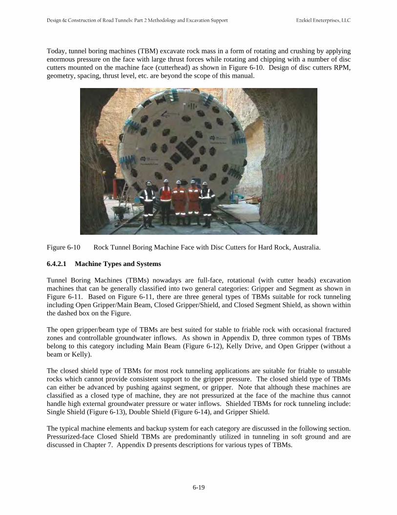
Today, tunnel boring machines (TBM) excavate rock mass in a form of rotating and crushing by applying enormous pressure on the face with large thrust forces while rotating and chipping with a number of disc cutters mounted on the machine face (cutterhead) as shown in Figure 6-10. Design of disc cutters RPM, geometry, spacing, thrust level, etc. are beyond the scope of this manual.
Figure 6-10 Rock Tunnel Boring Machine Face with Disc Cutters for Hard Rock, Australia.
6.4.2.1 Machine Types and Systems Tunnel Boring Machines (TBMs) nowadays are full-face, rotational (with cutter heads) excavation machines that can be generally classified into two general categories: Gripper and Segment as shown in Figure 6-11. Based on Figure 6-11, there are three general types of TBMs suitable for rock tunneling including Open Gripper/Main Beam, Closed Gripper/Shield, and Closed Segment Shield, as shown within the dashed box on the Figure. The open gripper/beam type of TBMs are best suited for stable to friable rock with occasional fractured zones and controllable groundwater inflows. As shown in Appendix D, three common types of TBMs belong to this category including Main Beam (Figure 6-12), Kelly Drive, and Open Gripper (without a beam or Kelly). The closed shield type of TBMs for most rock tunneling applications are suitable for friable to unstable rocks which cannot provide consistent support to the gripper pressure. The closed shield type of TBMs can either be advanced by pushing against segment, or gripper. Note that although these machines are classified as a closed type of machine, they are not pressurized at the face of the machine thus cannot handle high external groundwater pressure or water inflows. Shielded TBMs for rock tunneling include: Single Shield (Figure 6-13), Double Shield (Figure 6-14), and Gripper Shield. The typical machine elements and backup system for each category are discussed in the following section. Pressurized-face Closed Shield TBMs are predominantly utilized in tunneling in soft ground and are discussed in Chapter 7. Appendix D presents descriptions for various types of TBMs.
6-19
Design & Construction of Road Tunnels: Part 2 Methodology and Excavation Support Ezekiel Eneterprises, LLC
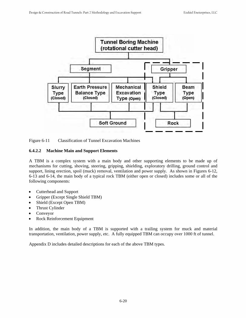
Figure 6-11 Classification of Tunnel Excavation Machines
6.4.2.2 Machine Main and Support Elements A TBM is a complex system with a main body and other supporting elements to be made up of mechanisms for cutting, shoving, steering, gripping, shielding, exploratory drilling, ground control and support, lining erection, spoil (muck) removal, ventilation and power supply. As shown in Figures 6-12, 6-13 and 6-14, the main body of a typical rock TBM (either open or closed) includes some or all of thefollowing components: • Cutterhead and Support• Gripper (Except Single Shield TBM)• Shield (Except Open TBM)• Thrust Cylinder• Conveyor• Rock Reinforcement Equipment In addition, the main body of a TBM is supported with a trailing system for muck and material transportation, ventilation, power supply, etc. A fully equipped TBM can occupy over 1000 ft of tunnel. Appendix D includes detailed descriptions for each of the above TBM types.
6-20
Design & Construction of Road Tunnels: Part 2 Methodology and Excavation Support Ezekiel Eneterprises, LLC
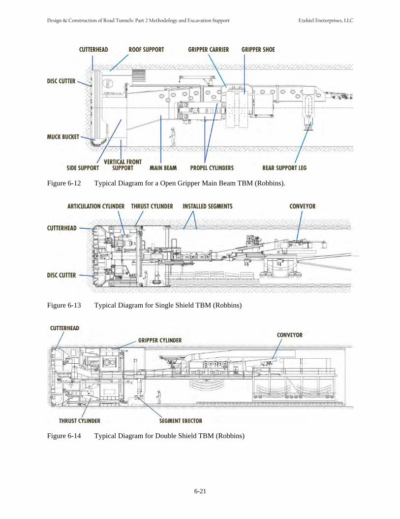
Figure 6-12 Typical Diagram for a Open Gripper Main Beam TBM (Robbins).
Figure 6-13 Typical Diagram for Single Shield TBM (Robbins)
Figure 6-14 Typical Diagram for Double Shield TBM (Robbins)
6-21
Design & Construction of Road Tunnels: Part 2 Methodology and Excavation Support Ezekiel Eneterprises, LLC

6.4.2.3 Compatible Ground Support Elements Most ground support elements discussed in Section 6.5 can be specified with the use of hard rock TBMs, especially if the TBMs are manufactured specifically for the project. • Rock reinforcement by roof bolting• Spiling/forepoling• Pre-injection• Steel ring beams with or without lagging (wire mesh, timber, etc.)• Invert segment• Shotcrete• Precast concrete segmental lining• Others Details of the above support measures are discussed in Section 6.5 of this Chapter, and Chapter 10 Tunnel Lining. 6.4.2.4 TBM Penetration Rate With a rock TBM, the penetration rate is affected by the following factors (from Robbins, 1990): • Total machine thrust• Cutter spacing• Cutter diameter and edge geometry • Cutterhead turning speed (revolutions per minute)• Cutterhead drive torque• Diameter of tunnel• Strength, hardness, and abrasivity of the rock• Jointing, weathering and other characteristics of the rock. However, penetration rate (an instantaneous parameter) by itself does not assure a high average advance rate. The latter requires a good combination of penetration rate and actual cutting time. In turn, actual cutting time is affected by the following factors: • Learning (start-up) curves• Downtime for changing cutters• Downtime for other machine repairs/maintenance• Overly complex designs• Back-up (trailing) systems• Tunnel support requirements• Muck handling• Water handling• Probe hole drilling, grouting• Available time (total and shift) The bottom line is that actual utilization typically runs in the range of 50% as shown by Figure 6-15.
6-22
Design & Construction of Road Tunnels: Part 2 Methodology and Excavation Support Ezekiel Eneterprises, LLC

3.90% Boring
Regrip
Cutters
TBM
Back-up 51.50%
Water, vent, cable
Muck haulage
Others
Figure 6-15 TBM Utilization on Two Norwegian Tunnels (After Robbins, 1990)
11.60%
5.60%
5%
4.90%
7.20%
10.40%
6.4.3 Roadheaders
Typical TBM’s cut circular tunnels which are the most practical cross section but not always the cross section that provides the most useable volume as a proportion of the total volume excavated. The Japanese and others have developed specialized machines with multiple heads that cut “slots” or other shapes that can be more efficient in providing useable volume.
Another approach to cutting an opening closer to some actual required section is the roadheader. The basic cutting tool for a roadheader is a very large milling head mounted on a boom, which boom, in turn, is mounted on tracks or within a shield. Figure 6-16 shows a large size roadheader. Corners must be cut to the curvature of the milling head, but the rest of the walls, crown and invert can be cut to almost any desired shape. In addition and in contrast to a TBM, a single roadheader can cut variable or odd shapes that otherwise would require TBM excavation in combination with drill and blast or drill and blast itself. Because of their adaptability, availability (a few months rather than a year or longer), and lower cost, roadheaders also are the method of choice for relatively short tunnels, say less than one mile in length.
Figure 6-16 AM 105 Roadheader, Australia
6-23
Design & Construction of Road Tunnels: Part 2 Methodology and Excavation Support Ezekiel Eneterprises, LLC

On the negative side, roadheaders are far less efficient on longer drives and in hard rock. The picks on the roadheader are something like 10% as efficient as TBM disks at removing rock, must be replaced very frequently and simply may not be effective in rock with an unconfined compressive strength greater than 20,000 psi (140MPa). Changes and improvements in roadheader design are on-going, however, and it is expected that this will result in constant improvements in these limitations. The following is a general list when roadheaders may be considered: • Rock strength below about 20000 - preferably below 15000.• Short runs, one of a kind openings• Odd, non-circular shapes• Connections, cross passages, etc• Low to moderate abrasivity • Preferably self supporting rock• No or small inclusions - chert etc• Nominal water pressure
6.4.4 Other Mechanized Excavation Methods Other mechanized excavation methods are being developed by specialized equipment manufacturers to address specific issues in mining and civil applications. A good example of such developments is the “Mobile Miner” developed by Robbins as a “non-circular hard rock cutting system to be applied to underground mine development” (Robbins, 1990). The mobile miner is described as follows: “A boom mounts a large cutter wheel with a transverse axis having rows of cutters arranged only on the periphery of the wheel. As the boom is swung from side to side an excavated shape is generated with a flat roof and floor and curved walls. Although the prototype machines have operated only with this side-swinging action, in order to cut openings which are better suited to vehicular tunnels the cutterhead boom must be elevated up and down and at the same time swung from side to side. In this way a horseshoe-shaped excavation can be generated. To date such machines have had some success in excavating openings approaching a horseshoe or slot configuration, but they are not commonly used. However, they do illustrate the points that shapes other than circular can be cut and that inventive and special-purpose machines are constantly being developed. 6.4.5 Sequential Excavation Method (SEM)/ New Austrian Tunneling Method (NATM) In actual practice, the Sequential Excavation Method (SEM)/New Austrian Tunneling Method (NATM) has been adapted from its original concept, which applied to rock tunnels only, to a more general concept that applies to tunnels in either soil or rock. Readers are referred to Chapter 9 “SEM Tunneling” for more detailed discussion. 6.5 TYPES OF ROCK REINFORCEMENT AND EXCAVATION SUPPORT 6.5.1 Excavation Support Options The purpose of an initial support (sometimes called temporary lining, or temporary support of excavation) in rock tunneling is to keep the opening open, stable and safe until the final lining is installed and
6-24
Design & Construction of Road Tunnels: Part 2 Methodology and Excavation Support Ezekiel Eneterprises, LLC
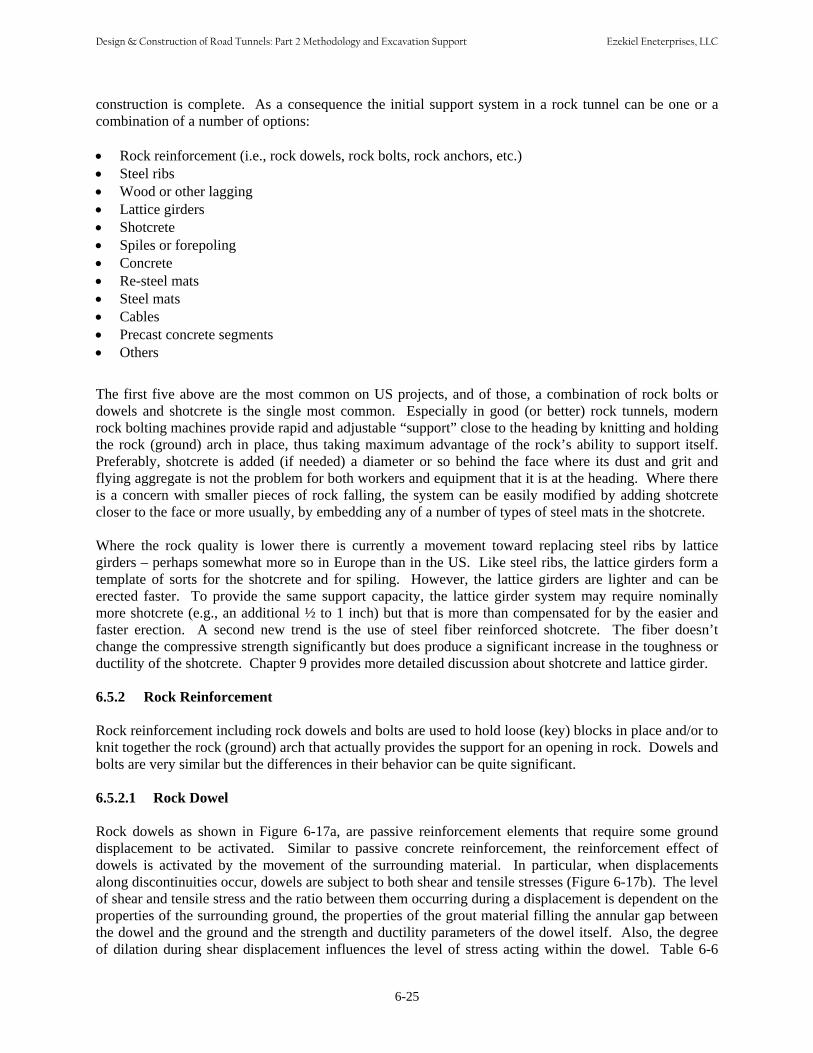
construction is complete. As a consequence the initial support system in a rock tunnel can be one or a combination of a number of options: • Rock reinforcement (i.e., rock dowels, rock bolts, rock anchors, etc.)• Steel ribs• Wood or other lagging• Lattice girders• Shotcrete• Spiles or forepoling• Concrete• Re-steel mats • Steel mats • Cables• Precast concrete segments • Others
The first five above are the most common on US projects, and of those, a combination of rock bolts or dowels and shotcrete is the single most common. Especially in good (or better) rock tunnels, modern rock bolting machines provide rapid and adjustable “support” close to the heading by knitting and holding the rock (ground) arch in place, thus taking maximum advantage of the rock’s ability to support itself. Preferably, shotcrete is added (if needed) a diameter or so behind the face where its dust and grit and flying aggregate is not the problem for both workers and equipment that it is at the heading. Where there is a concern with smaller pieces of rock falling, the system can be easily modified by adding shotcrete closer to the face or more usually, by embedding any of a number of types of steel mats in the shotcrete. Where the rock quality is lower there is currently a movement toward replacing steel ribs by lattice girders – perhaps somewhat more so in Europe than in the US. Like steel ribs, the lattice girders form a template of sorts for the shotcrete and for spiling. However, the lattice girders are lighter and can be erected faster. To provide the same support capacity, the lattice girder system may require nominally more shotcrete (e.g., an additional ½ to 1 inch) but that is more than compensated for by the easier and faster erection. A second new trend is the use of steel fiber reinforced shotcrete. The fiber doesn’t change the compressive strength significantly but does produce a significant increase in the toughness or ductility of the shotcrete. Chapter 9 provides more detailed discussion about shotcrete and lattice girder. 6.5.2 Rock Reinforcement Rock reinforcement including rock dowels and bolts are used to hold loose (key) blocks in place and/or to knit together the rock (ground) arch that actually provides the support for an opening in rock. Dowels and bolts are very similar but the differences in their behavior can be quite significant. 6.5.2.1 Rock Dowel Rock dowels as shown in Figure 6-17a, are passive reinforcement elements that require some ground displacement to be activated. Similar to passive concrete reinforcement, the reinforcement effect of dowels is activated by the movement of the surrounding material. In particular, when displacements along discontinuities occur, dowels are subject to both shear and tensile stresses (Figure 6-17b). The level of shear and tensile stress and the ratio between them occurring during a displacement is dependent on the properties of the surrounding ground, the properties of the grout material filling the annular gap between the dowel and the ground and the strength and ductility parameters of the dowel itself. Also, the degree of dilation during shear displacement influences the level of stress acting within the dowel. Table 6-6
6-25
Design & Construction of Road Tunnels: Part 2 Methodology and Excavation Support Ezekiel Eneterprises, LLC

describes various types of rock dowels. In addition, Table 9-5 summarizes commonly used rock dowels and application considerations for the installation as part of initial support in SEM tunneling in rock.
For example a #9 dowel 10 ft. long will have to elongate almost 0.2 inch before it develops its full design capacity of 40,000 lb. This may not be a concern in most applications where there is some interlocking between rock blocks due to the natural asperities on discontinuity surface.
(a)
(b)
Figure 6-17 (a) Temporary Rock Dowel; (b) Schematic Function of a Rock Dowel under Shear
6.5.2.2 Rock Bolts Rock bolts (Figure 6-18) have a friction or grout anchor in the rock and are tensioned as soon as that anchorage is attained to actively introduce a compressive force into the surrounding ground. This axial force acts upon the rock mass discontinuities thus increasing their shear capacity and is generated by pre-tensioning of the bolt. The system requires a ‘bond length’ to enable the bolt to be tensioned. Rock bolts frequently are fully bonded to the surrounding ground after tensioning, for long-term load transfer considerations. They may or may not be grouted full length. In any case, bolts begin to support or knit the rock as soon as they are tensioned, that is, the rock does not have time to begin to move before the bolt becomes effective. Table 6-6 describes various types of rock bolts. In addition, Table 9-5
6-26
Design & Construction of Road Tunnels: Part 2 Methodology and Excavation Support Ezekiel Eneterprises, LLC
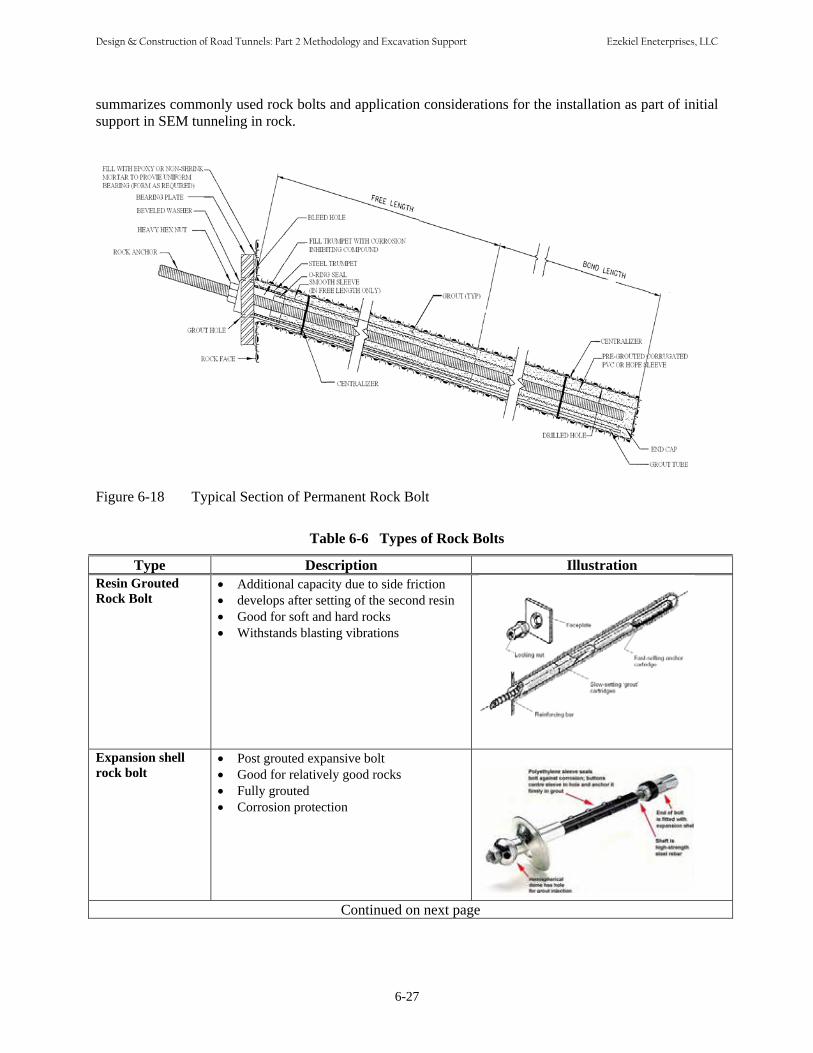
summarizes commonly used rock bolts and application considerations for the installation as part of initial support in SEM tunneling in rock.
Figure 6-18 Typical Section of Permanent Rock Bolt
Table 6-6 Types of Rock Bolts
Type Description IllustrationResin Grouted Rock Bolt
• Additional capacity due to side friction• develops after setting of the second resin• Good for soft and hard rocks• Withstands blasting vibrations
Expansion shell rock bolt
• Post grouted expansive bolt• Good for relatively good rocks• Fully grouted• Corrosion protection
Continued on next page
6-27
Design & Construction of Road Tunnels: Part 2 Methodology and Excavation Support Ezekiel Eneterprises, LLC

6-28
Table 6-6 (continued) Common Types of Rock Bolts
Type Description IllustrationsSplit set stabilizers • Slotted bolt is inserted into a slightly
smaller diameter hole• Induced radial stress, anchors the system
in place by friction• Mainly for mining, and under mild rock
burst conditions• It slips instead of suddenly failing• Limited load handling
Swellex • Length up to 12 m• Hole diameter =32-52 mm• Tensile load= 100 -240 kN• Inflation pressure ≈ 30 Mpa• Instant full load bearing capacity• Fast application• Not sensitive to blasting• Elongation range: 20-30%
Self Drilling • Drilling, installation, and injection in oneAnchor single operational step
• No pre-drilling of a borehole by using acasing tube and extension rods withsubsequent anchor installation necessary
• Minor space requirement for anchorinstallation
• Optimized machinery and manpowerrequirements
Cablebolt • Primarily used to support largereinforcement underground structures, i.e mining
applications, underground power cavernsetc.
• Can handle high loads• Tendons are grouted with concrete mix• At very high loads the governing
parameter is most often the bond betweenthe tendon and the grout
• Cable capacity is confining stressdependent
Design & Construction of Road Tunnels: Part 2 Methodology and Excavation Support Ezekiel Eneterprises, LLC

6.5.3 Ribs and Lagging
Ribs and lagging (Figure 6-19) are not used as much now as they were even a couple of decades ago. However, there are still applications where their use is appropriate, such as unusual shapes, intersections, short starter tunnels for TBM, and reaches of tunnel where squeezing or swelling ground may occur.
In 1946, Proctor and White (with major input from Dr. Karl Terzaghi) wrote the definitive volume “Rock Tunneling with Steel Supports”. Their design approach assumes the ribs are acted upon by axial thrust and by bending moments, the latter a function of the spacing of the lagging or blocking behind the ribs. This approach is still valid when wood or other blocking is used with steel ribs and hence will not be repeated here. In today’s applications, steel ribs are often installed with shotcrete being used instead of wood for the blocking (lagging) material. When shotcete is used, it often does not fill absolutely the entire void between steel and rock. Hence, with properly applied shotcrete it is recommended that the maximum blocking point spacing be taken as 20 in. and the design proceed according to the Proctor and White procedure.
Figure 6-19 Steel Rib Support
6-29
Design & Construction of Road Tunnels: Part 2 Methodology and Excavation Support Ezekiel Eneterprises, LLC
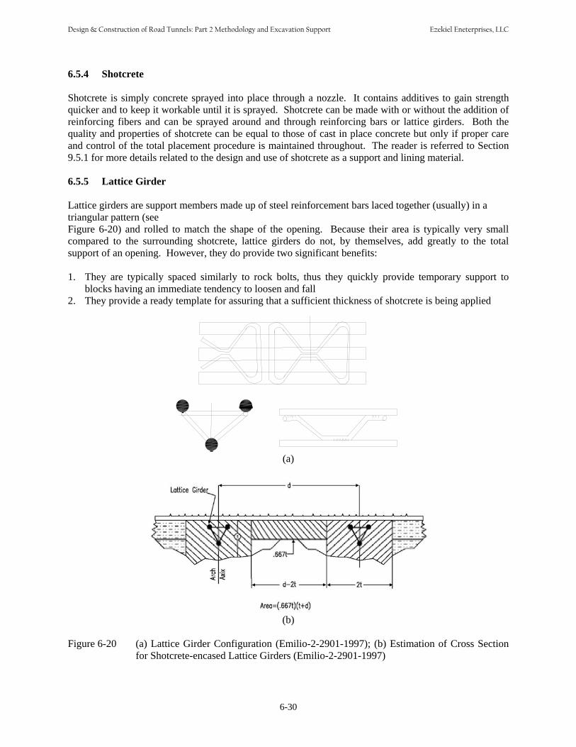
6.5.4 Shotcrete Shotcrete is simply concrete sprayed into place through a nozzle. It contains additives to gain strength quicker and to keep it workable until it is sprayed. Shotcrete can be made with or without the addition of reinforcing fibers and can be sprayed around and through reinforcing bars or lattice girders. Both the quality and properties of shotcrete can be equal to those of cast in place concrete but only if proper care and control of the total placement procedure is maintained throughout. The reader is referred to Section 9.5.1 for more details related to the design and use of shotcrete as a support and lining material. 6.5.5 Lattice Girder Lattice girders are support members made up of steel reinforcement bars laced together (usually) in a triangular pattern (see Figure 6-20) and rolled to match the shape of the opening. Because their area is typically very small compared to the surrounding shotcrete, lattice girders do not, by themselves, add greatly to the total support of an opening. However, they do provide two significant benefits: 1. They are typically spaced similarly to rock bolts, thus they quickly provide temporary support to
blocks having an immediate tendency to loosen and fall2. They provide a ready template for assuring that a sufficient thickness of shotcrete is being applied
(a)
(b)
Figure 6-20 (a) Lattice Girder Configuration (Emilio-2-2901-1997); (b) Estimation of Cross Sectionfor Shotcrete-encased Lattice Girders (Emilio-2-2901-1997)
6-30
Design & Construction of Road Tunnels: Part 2 Methodology and Excavation Support Ezekiel Eneterprises, LLC

Generally, lattice girders are used much more frequently in tunnels driven by the sequential excavation method. Therefore, the reader is directed to Chapters 9 for further discussion of these supports.
6.5.6 Spiles and Forepoles
Spiles and forepoles (Figure 6-21) are used interchangeably to describe support elements consisting of pipes or pointed boards or rods driven ahead of the steel sets or lattice girders. These elements (herein called spiles) provide temporary overhead protection while excavation for and installation of the next set or girder is accomplished. Typically, spiles are driven in an overlapping arrangement as shown in Figure 6-21 so that there is never a gap in coverage. Design of spiles is best described as “intuitive” as it must bekept flexible and constantly adjusted in the field as the ground behavior is observed during theconstruction. A working first approximation of design load might be a height of rock equal to 0.1B to0.25B, where B is the width of the opening. Section 9.5.4.1 provides discussions for pre-supportmeasures involving spiling or grouted pipe arch canopies that bridge over the unsupported excavationround.
Figure 6-21 Spiling (Forepoling) Method of Supporting Running Ground
6.5.7 Precast Segment Lining Tunnel lining consisting of precast segments may be used in single-pass or double pass lining systems to support rock loadings and water pressures. Generally the concrete segments are reinforced either with reinforcement bar or fiber. The segment ring usually consists of five to seven segments with a key segment. The ring division and the segment dimension have to be optimized according to project specific requirements such as tunnel diameter, maximum size for transport and installation (erector), and number of thrust jacks and their distribution over the range of the ring. Figure 6-22 illustrates a typical seven ring plus one key segment concrete lining. A typical circumferential dowel (Figure 6-22a) and radial bolt (Figure 6-22b) are also presented. The precast segment concrete lining is mostly used in TBM tunnel construction projects and, at this time, more frequently in soft ground tunnels. The segmental ring is erected in the TBM tail shield and during the advance, the rams act on the ring. The ring never can be independent from the TBM, hence the design of the TBM and the segmental ring must be harmonized. Rams must act on prepared sections of the ring, rolling of the tunnel shield and the ring must be taken into account. The ram axis should be identical with the ring axis. The ring taper should be designed according to the TBM curve drive capabilities and not only according to the designed tunnel axis. Details of design considerations for precast segment lining will be discussed in Chapter 10.
6-31
Design & Construction of Road Tunnels: Part 2 Methodology and Excavation Support Ezekiel Eneterprises, LLC

6.6 DESIGN AND EVALUATION OF TUNNEL SUPPORTS
There exists a wide range of tunnel support systems as shown in previous sections. In recent years the tunneling community has moved away from support to reinforcement as the basic approach. That is, from providing heavy structures, primarily ribs and lagging, to using rock bolts and dowels, spiling, lattice girders and shotcrete. In all of these latter systems the goal is to keep the rock from moving and blocks from loosening thereby keeping a large dead load of rock from coming onto the support system; that is holding the rock together and causing the ground around the opening to form a natural and self supporting ground arch around the opening.
(a) (b) Figure 6-22 A Typical Seven Segment and a Key Segment Precast Segment Lining: (a) Circumferential
Dowel; (b) Radial Bolt
6-32
Design & Construction of Road Tunnels: Part 2 Methodology and Excavation Support Ezekiel Eneterprises, LLC

This trend was started in the U.S. on the Washington D.C. subway system where on two successive sections the amount of structural steel support was reduced by three quarters. This was accomplished by holding the rock in place with rock bolts until the final lining of shotcrete with light ribs at four foot centers could be installed and become effective in causing the rock to help support itself. In contrast, the previous section relied upon steel ribs to carry the dead (rock) loads and thus required twice the weight of steel members at one-half the spacing.
Tunnel support design is an iterative process including assumptions on support type installed and evaluating the support pressure it provides. Table 6-7 lists typical tunnel support systems used in the current practice for various ground conditions. This table can be used for the initial selection of the support system to initiate the interaction and iteration.
Table 6-7 Typical Initial Support and Lining Systems Used in the Current Practice (TRB, 2006)
Ground Rock bolts Rock bolts with wire
mesh
Rock bolts with
shotcrete
Steel ribs and lattice girder with shotcrete
Cast-inplace
concrete
Concrete segments
Strong rock
Medium Rock
Soft Rock
Soil
O OO OO O O
O O OO O OO O OO O O
In making the selection of support measures for a given project, however, the full range of possible support system should be considered simply because each project is unique. Factors to be considered include the following: 1. Local custom: contractors like to use systems with which they are familiar.2. Relative costs: for example, is it cost effective to design bolts with suitable corrosion resistance to
assure their permanence.3. Availability of materials This Section introduces design practice and evaluation of initial tunnel supports, including empirical, analytical and numerical methods. Design of underground structures can be based largely on previous experience and construction observations to assess expected performances of specified ground support systems. 6.6.1 Empirical Method Terzaghis’s tunnelman’s classification (Table 6-1) of rock condition and recommended rock loadings, expressed as a function of tunnel size are presented in Table 6-8. These recommendations sprang from Terzaghi’s observations in the field and his trap door experiments in the laboratory.
6-33
Design & Construction of Road Tunnels: Part 2 Methodology and Excavation Support Ezekiel Eneterprises, LLC

Table 6-8 Suggested Rock Loadings from Terzaghi’s Rock Mass Classification
Rock condition Rock Load, Hp (ft) Remarks
Hard and intact Zero Light lining, required only if spalling or popping occurs
Hard stratified or schistose 0 to 0.5 B Light support. Load may change erratically from point to point Massive, moderately jointed 0 to 0.25 B
Moderately blocky and seamy 0.25B to 0.35 (B + Ht)
No side pressure
Very blocky and seamy (0.35 to 1.10) (B + Ht)
Little or no side pressure
Completely crushed but chemically intact 1.10 (B + Ht)
Considerable side pressure. Softening effect of seepage towards bottom of tunnel requires either continuous support for lower ends of ribs or circular ribs
Squeezing rock, moderate depth
(1.10 to 2.10) (B + Ht) Heavy side pressure, invert struts required.
Circular ribs are recommended Squeezing rock, great depth (2.10 to 4.50) (B + Ht)
Swelling rock Up to 250ft. irrespective of value of (B + Ht)
Circular ribs required. In extreme cases use yielding support
As a first approximation to rock bolt or dowel selection, Cording et al. (1971) provides a compilation of case histories for underground rock excavations based on excavation sizes (span width and height), as shown in Figure 6-23 and Figure 6-24, the following are recommended by Cording et al. (1971): • A crown support pressure equal to a rock load having a height of 0.3B.• A sidewall support pressure of 0.15H.• A crown bolt length of 0.33B.• A sidewall bolt length of 0.33H. where B is the opening width. In rock with an RQD greater than 75%, it is expected that the sidewall pressure typically will be smaller (often zero) than estimated above and only spot bolts to hold obvious wedges will be required. Two most widely used rock mass classifications, RMR and Q, incorporate geotechnical, geometrical, and engineering parameters. Using rock mass classifications and equivalent dimension of the tunnel, which is defined as ratio of dimension of tunnel and ESR (Excavation Support Ratio), Barton et al. (1974) proposed a number of support categories and the chart was updated by Grimstad and Barton (1993). The updated chart using the Q system is presented in Figure 6-25. Table 6-9 presents how the RMR is applied to support design of a tunnel with 10 m span.
6-34
Design & Construction of Road Tunnels: Part 2 Methodology and Excavation Support Ezekiel Eneterprises, LLC
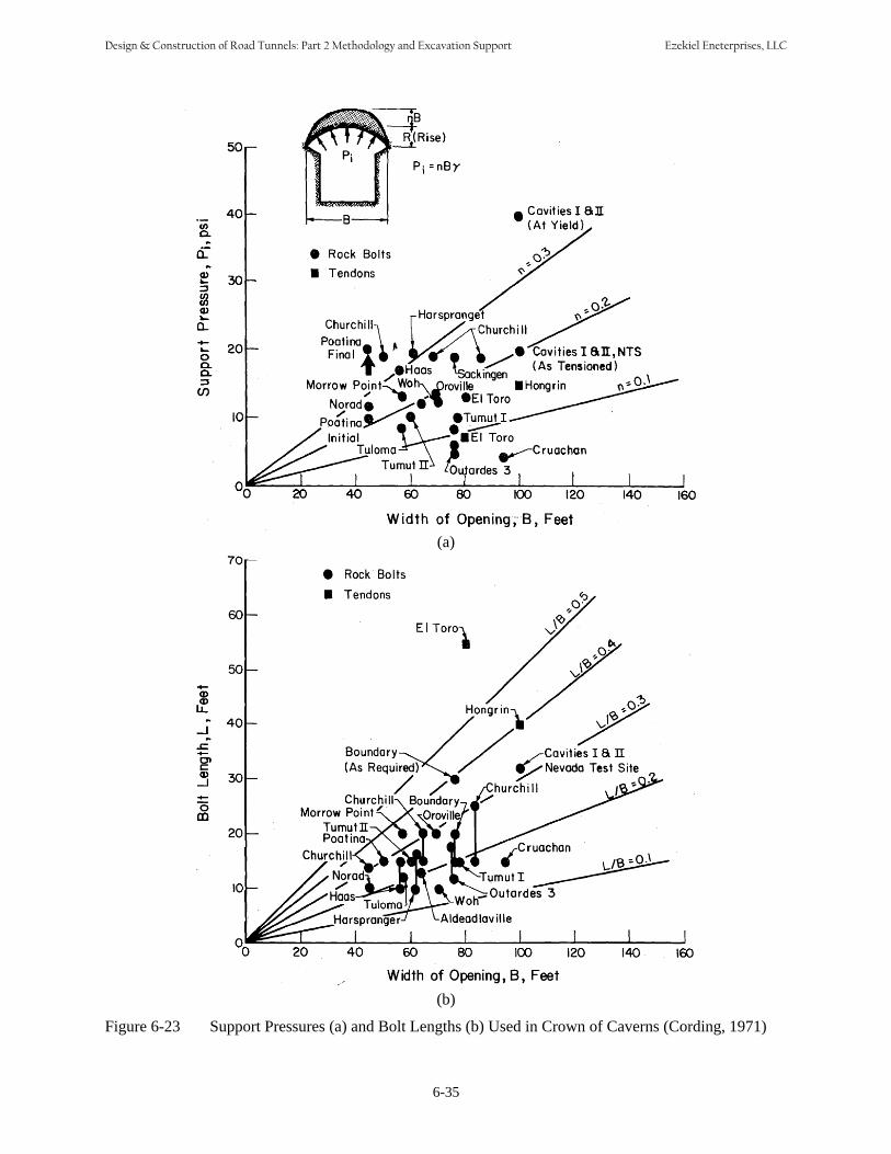
(a)
(b)
Figure 6-23 Support Pressures (a) and Bolt Lengths (b) Used in Crown of Caverns (Cording, 1971)
6-35
Design & Construction of Road Tunnels: Part 2 Methodology and Excavation Support Ezekiel Eneterprises, LLC
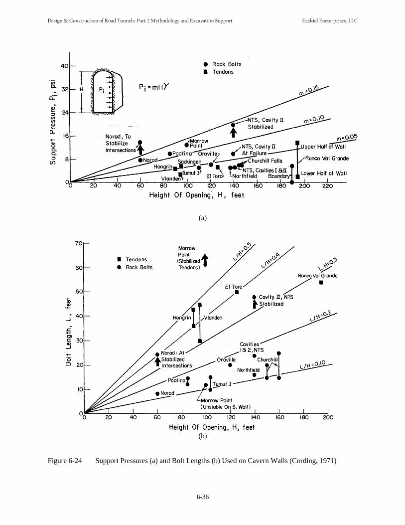
(a)
(b)
Figure 6-24 Support Pressures (a) and Bolt Lengths (b) Used on Cavern Walls (Cording, 1971)
6-36
Design & Construction of Road Tunnels: Part 2 Methodology and Excavation Support Ezekiel Eneterprises, LLC

Reinforcing Categories: (1) Unsupported (2) Spot Bolting (3) Systematic Bolting (4) Systematic bolting with 40-100 mm unreinforced shotcrete (5) Fiber reinforced shotcrete, 50 - 90 mm, and bolting (6) Fiber reinforced shotcrete, 90 - 120 mm, and bolting (7) Fiber reinforced shotcrete, 120 - 150 mm, and bolting (8) Fiber reinforced shotcrete, > 150 mm with reinforced ribs of shotcrete and bolting (9) Cast concrete lining
Figure 6-25 Rock Support Requirement using Rock Mass Quality Q System
It should be noted that “the Q-system has its best applications in jointed rock mass where instability is caused by rock falls. For most other types of ground behavior in tunnels the Q-system, like most other empirical (classification) methods has limitations. The Q support chart gives an indication of the support to be applied, and it should be tempered by sound and practical engineering judgment” (Palmstream and Broch, 2006). Also note that the Q-system was developed from over 1000 tunnel projects, most of which are in Scandinavia and all of which were excavated by drill and blast methods. When excavation is by TBM there is considerably less disturbance to the rock than there is with drill and blast. Based upon study of a much smaller data base, Barton (1991) recommended that the Q for TBM excavation be increased by a factor of 2 for Qs between 4 and 30.
6-37
Design & Construction of Road Tunnels: Part 2 Methodology and Excavation Support Ezekiel Eneterprises, LLC

2 + 0.15BL = , in meters 6-3ESR
2 J −1/ 3
= n QProof (MPa) 6-53Jr
Table 6-9 Guidelines for Excavation and Support of 10 m Span Rock Tunnels in Accordance with the RMR System (after Bieniawski, 1989)
Rock mass class Excavation
Rock bolts (20 mm diameter, fully grouted)
Shotcrete Steel sets
I – very good rock RMR: 81-100
Full face 3 m advance
Generally no support required except spot bolting
II – Good rock Full face, 1-1.5 m advance. Locally, bolts in 50 mm in None RMR: 61-80 Complete support 20 m from
face crown 3 m long, spaced 2.5 m with occasional wire mesh
crown where required
III – Fair rock Top heading and bench 1.5-3 Systematic bolts 4 m 50-100 mm None RMR: 41-60 m advance in top heading.
Commence support after each blast. Complete support 10 m from face
long spaced 1.5-2 m in crown and walls with wire mesh in crown
in crown and30 mm insides
IV – Poor rock Top heading and bench 1.0 Systematic bolts 4-5 100-150 mm Light to RMR: 21-40 1.5 m advance in top heading.
Install support concurrently with excavation, 10 m from face
m long, spaced 1-1.5 m in crown and walls with wire mesh
in crown and100 mm insides
medium ribs spaced 1.5 m where required
V – Very poor Multiple drifts Systematic bolts 5.6 150-200 mm Medium to rock RMR: < 20 0.5-1.5 m advance in top m long, spaced 1-1.5 in crown, 150 heavy ribs
heading. Install support m in crown and walls mm in sides, spaced steel concurrently with excavation. with wire mesh. Bolt and 50 mm lagging and Shotcrete as soon as possible invert. on face forepoling if after blasting. required.
Close invert. Note Table 6-9 above assumes excavation by drill and blast. Barton et al. (1980) proposed rock bolt length, maximum unsupported spans and roof support pressures to supplement the support recommendations. The length of rock bolts, L can be estimated from the excavation width, B and the Excavation Support Ratio (ESR) as follow:
The maximum unsupported span can be estimated from:
Maximum Unsupported Span = 2 ESR Q0.4 , in meters 6-4 Grimstad and Barton (1993) proposed a relationship between Q value and the permanent roof support pressure, Proof as follow:
6-38
Design & Construction of Road Tunnels: Part 2 Methodology and Excavation Support Ezekiel Eneterprises, LLC

The value of Excavation Support Ratio (ESR) is related to the degree of security which is demanded of the support system installed to maintain stability of the excavation. Barton et al. (1974) suggested ESR values for various types of underground structures as presented in Table 6-10. An ESR value of 1.0 is recommended for civil tunnel projects.
Table 6-10 Excavation Support Ratio (ESR) Values for Various Underground Structures (Barton et al., 1974)
Excavation Category Suggested ESR Value
A Temporary mine openings 3 – 5
B Permanent mine openings, water tunnels for hydro power (excluding high pressure penstocks), pilot tunnels, drifts and headings for large excavations. 1.6
C Storage rooms, water treatment plants, minor road and railway tunnels, surge chambers, access tunnels 1.3
D Power stations, major road and railway tunnels, civil defense chambers, portal intersections 1.0
E Underground nuclear power stations, railway stations, sports and public facilities, factories 0.8
6.6.2 Analytical Methods The state of stress due to tunnel excavation can be calculated from analytical elastic closed form solutions. Kirsch’s elastic closed form solution is one of the commonly used analytical solutions and is presented in Appendix E. The closed form solution is restricted to simple geometries and material models, and therefore often of limited practical value. However, the solution is considered to be a good tool for a “sanity check” of the results obtained from numerical analyses. The interaction between rock support and surrounding ground is well described by the ground reaction curve (Figure 6-26), which relates internal support pressure to tunnel wall convergence. General description of ground reaction curve is well described Hoek (1999).
(a) (b)
Figure 6-26 Ground Reaction Curves between Support Pressure and Displacement (Hoek et al., 1995)
6-39
Design & Construction of Road Tunnels: Part 2 Methodology and Excavation Support Ezekiel Eneterprises, LLC
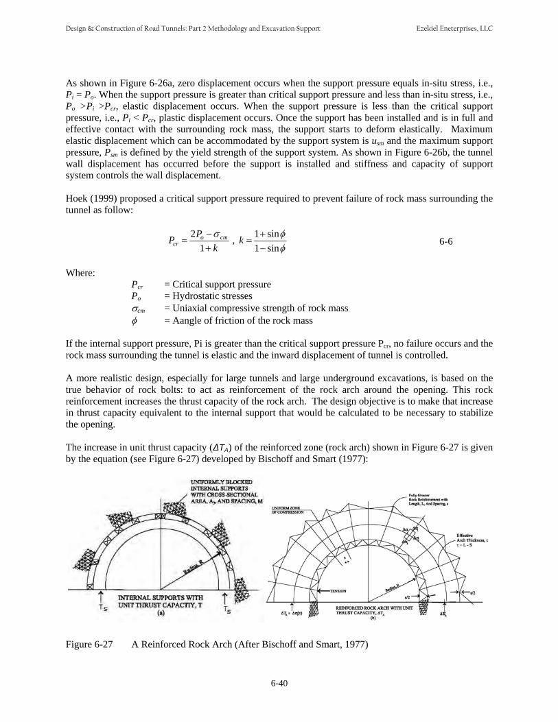
As shown in Figure 6-26a, zero displacement occurs when the support pressure equals in-situ stress, i.e., Pi = Po. When the support pressure is greater than critical support pressure and less than in-situ stress, i.e., Po >Pi >Pcr, elastic displacement occurs. When the support pressure is less than the critical support pressure, i.e., Pi < Pcr, plastic displacement occurs. Once the support has been installed and is in full and effective contact with the surrounding rock mass, the support starts to deform elastically. Maximum elastic displacement which can be accommodated by the support system is usm and the maximum support pressure, Psm is defined by the yield strength of the support system. As shown in Figure 6-26b, the tunnel wall displacement has occurred before the support is installed and stiffness and capacity of support system controls the wall displacement.
Hoek (1999) proposed a critical support pressure required to prevent failure of rock mass surrounding the tunnel as follow:
2Po −σ cm 1+ sinφPcr = , k = 6-61+ k 1− sinφ
Where:
Pcr = Critical support pressure Po = Hydrostatic stresses σcm = Uniaxial compressive strength of rock mass φ = Aangle of friction of the rock mass
If the internal support pressure, Pi is greater than the critical support pressure Pcr, no failure occurs and the rock mass surrounding the tunnel is elastic and the inward displacement of tunnel is controlled. A more realistic design, especially for large tunnels and large underground excavations, is based on the true behavior of rock bolts: to act as reinforcement of the rock arch around the opening. This rock reinforcement increases the thrust capacity of the rock arch. The design objective is to make that increase in thrust capacity equivalent to the internal support that would be calculated to be necessary to stabilize the opening. The increase in unit thrust capacity (ΔTA) of the reinforced zone (rock arch) shown in Figure 6-27 is given by the equation (see Figure 6-27) developed by Bischoff and Smart (1977):
Figure 6-27 A Reinforced Rock Arch (After Bischoff and Smart, 1977)
6-40
Design & Construction of Road Tunnels: Part 2 Methodology and Excavation Support Ezekiel Eneterprises, LLC
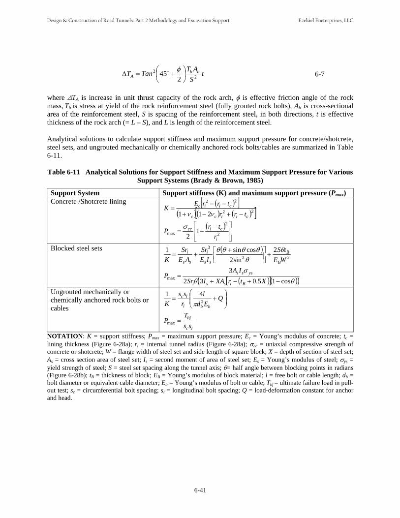
2 ⎛ o φ ⎞ T AΔTA = Tan ⎜45 + ⎟ b
2 b t 6-7
⎝ 2 ⎠ S
where ΔTA is increase in unit thrust capacity of the rock arch, φ is effective friction angle of the rock mass, Tb is stress at yield of the rock reinforcement steel (fully grouted rock bolts), Ab is cross-sectional area of the reinforcement steel, S is spacing of the reinforcement steel, in both directions, t is effective thickness of the rock arch (= L – S), and L is length of the reinforcement steel.
Analytical solutions to calculate support stiffness and maximum support pressure for concrete/shotcrete, steel sets, and ungrouted mechanically or chemically anchored rock bolts/cables are summarized in Table 6-11.
Table 6-11 Analytical Solutions for Support Stiffness and Maximum Support Pressure for Various Support Systems (Brady & Brown, 1985)
Support System Support stiffness (K) and maximum support pressure (Pmax) Concrete /Shotcrete lining ( )[ ]
( ) ( ) ( )[ ]22
22
211 ciicc
ciic
trr trrEK
−+−+
−− =
νν
( ) ⎥⎥⎦
⎤
⎢⎢ ⎣
⎡ −−= 2
2
max 1 2 i
cicc
r trP σ
Blocked steel sets ( ) 22
3 2 2sin
cossin1 E W
S t E I Sr
E A Sr
K B
B
ss
i
ss
i θ θ
θθθ θ ⎥⎦+⎤ ⎢⎣
⎡ ++=
( )[ ]( ){ θ }θ
σ
cos10.532 3
max −+−+=
XtrXAISr A I
P Bissi
ysss
Ungrouted mechanically or chemically anchored rock bolts or cables
⎟⎟⎠
⎞ ⎜⎜⎝
⎛ += Q
d E l
r s s
K bbi
lc 2
41 π
lc
bf
s s T
P =max
NOTATION: K = support stiffness; Pmax c c
lining thickness (Figure 6-28a); ri = internal tunnel radius (Figure 6-28a); σcc = uniaxial compressive strength of concrete or shotcrete; W = flange width of steel set and side length of square block; X = depth of section of steel set; As = cross section area of steel set; Is = second moment of area of steel set; Es = Young’s modulus of steel; σys = yield strength of steel; S = steel set spacing along the tunnel axis; θ= half angle between blocking points in radians (Figure 6-28b); tB = thickness of block; EB = Young’s modulus of block material; l = free bolt or cable length; db = bolt diameter or equivalent cable diameter; Eb = Young’s modulus of bolt or cable; Tbf = ultimate failure load in pullout test; sc = circumferential bolt spacing; sl = longitudinal bolt spacing; Q = load-deformation constant for anchor and head.
6-41
= maximum support pressure; E = Young’s modulus of concrete; t =
Design & Construction of Road Tunnels: Part 2 Methodology and Excavation Support Ezekiel Eneterprises, LLC

(a) (b)
Figure 6-28 Support Systems: (a) Concrete / Shotcrete Lining, (b) Blocked Steel Set
The size and shape of wedges formed in the rock mass surrounding a tunnel excavation depend upon geometry and orientation of the tunnel and also upon the orientation of the joint sets. The three dimensional geometry problems can be solved by computer programs such as UNWEDGE (Rocscience Inc.). UNWEDGE is a three dimensional stability analysis and visualization program for underground excavations in rock containing intersecting structural discontinuities. UNWEDGE provides enhanced support models for bolts, shotcrete and support pressures, the ability to optimize tunnel orientation and an option to look at different combinations of three joint sets based on a list of more than three joint sets. In UNWEDGE, safety factors are calculated for potentially unstable wedges and support requirements can be modeled using various types of pattern and spot bolting and shotcrete. Figure 6-28 presents a wedge formed by UNWEDGE on a horse-shoe shape tunnel.
(a) (b)
Figure 6-29 UNWEDGE Analysis: (a) Wedges Formed Surrounding a Tunnel; (b) Support Installation
6-42
Design & Construction of Road Tunnels: Part 2 Methodology and Excavation Support Ezekiel Eneterprises, LLC
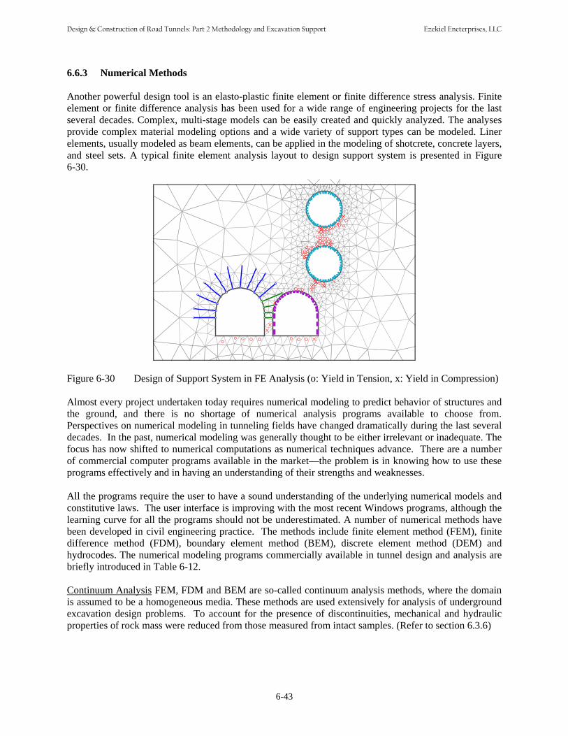
6.6.3 Numerical Methods Another powerful design tool is an elasto-plastic finite element or finite difference stress analysis. Finite element or finite difference analysis has been used for a wide range of engineering projects for the last several decades. Complex, multi-stage models can be easily created and quickly analyzed. The analyses provide complex material modeling options and a wide variety of support types can be modeled. Liner elements, usually modeled as beam elements, can be applied in the modeling of shotcrete, concrete layers, and steel sets. A typical finite element analysis layout to design support system is presented in Figure 6-30.
Figure 6-30 Design of Support System in FE Analysis (o: Yield in Tension, x: Yield in Compression)
Almost every project undertaken today requires numerical modeling to predict behavior of structures and the ground, and there is no shortage of numerical analysis programs available to choose from. Perspectives on numerical modeling in tunneling fields have changed dramatically during the last several decades. In the past, numerical modeling was generally thought to be either irrelevant or inadequate. The focus has now shifted to numerical computations as numerical techniques advance. There are a number of commercial computer programs available in the market—the problem is in knowing how to use these programs effectively and in having an understanding of their strengths and weaknesses. All the programs require the user to have a sound understanding of the underlying numerical models and constitutive laws. The user interface is improving with the most recent Windows programs, although the learning curve for all the programs should not be underestimated. A number of numerical methods have been developed in civil engineering practice. The methods include finite element method (FEM), finite difference method (FDM), boundary element method (BEM), discrete element method (DEM) and hydrocodes. The numerical modeling programs commercially available in tunnel design and analysis are briefly introduced in Table 6-12. Continuum Analysis FEM, FDM and BEM are so-called continuum analysis methods, where the domain is assumed to be a homogeneous media. These methods are used extensively for analysis of underground excavation design problems. To account for the presence of discontinuities, mechanical and hydraulic properties of rock mass were reduced from those measured from intact samples. (Refer to section 6.3.6)
6-43
Design & Construction of Road Tunnels: Part 2 Methodology and Excavation Support Ezekiel Eneterprises, LLC
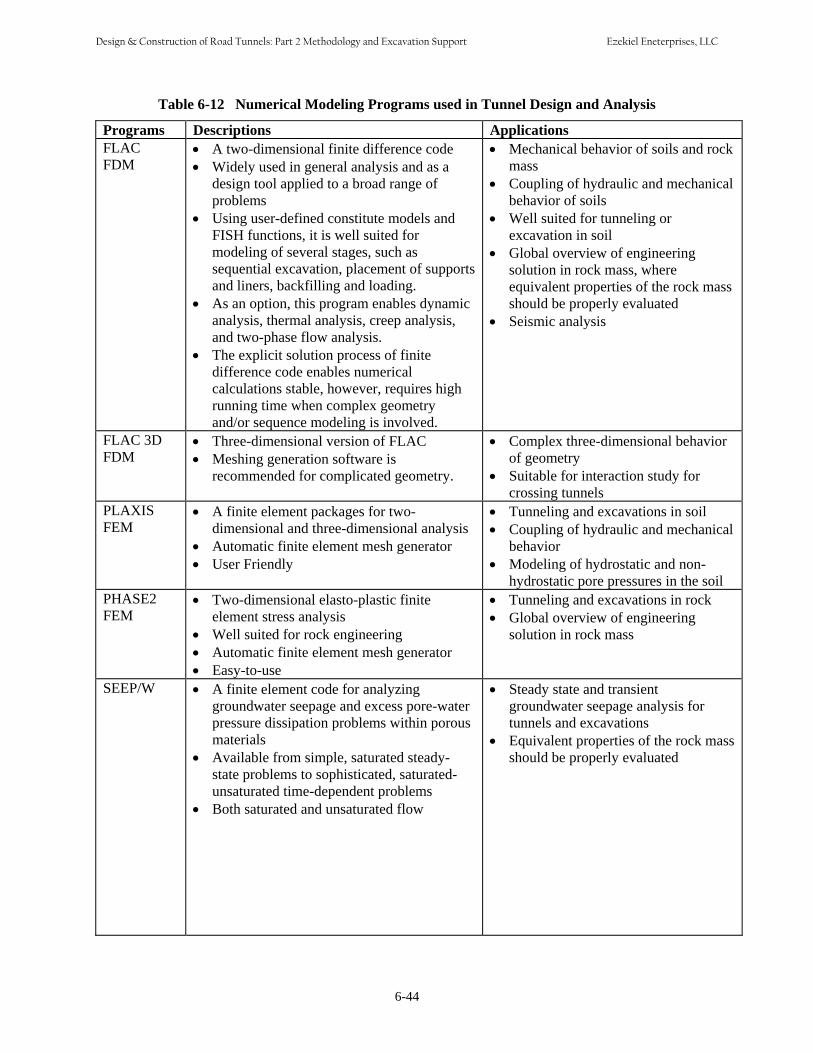
Table 6-12 Numerical Modeling Programs used in Tunnel Design and Analysis
6-44
Programs Descriptions Applications FLAC • A two-dimensional finite difference code • Mechanical behavior of soils and rockFDM • Widely used in general analysis and as a mass
•
•
•
design tool applied to a broad range ofproblemsUsing user-defined constitute models andFISH functions, it is well suited formodeling of several stages, such assequential excavation, placement of supportsand liners, backfilling and loading.As an option, this program enables dynamicanalysis, thermal analysis, creep analysis,and two-phase flow analysis.The explicit solution process of finitedifference code enables numericalcalculations stable, however, requires high
running time when complex geometryand/or sequence modeling is involved.
•
•
•
•
Coupling of hydraulic and mechanicalbehavior of soilsWell suited for tunneling orexcavation in soilGlobal overview of engineeringsolution in rock mass, whereequivalent properties of the rock massshould be properly evaluatedSeismic analysis
FLAC 3D • Three-dimensional version of FLAC • Complex three-dimensional behaviorFDM • Meshing generation software is
recommended for complicated geometry. • of geometry Suitable for interaction study forcrossing tunnels
PLAXIS • A finite element packages for two • Tunneling and excavations in soil FEM
• •
dimensional and three-dimensional analysisAutomatic finite element mesh generatorUser Friendly
•
•
Coupling of hydraulic and mechanicalbehaviorModeling of hydrostatic and non-hydrostatic pore pressures in the soil
PHASE2 • Two-dimensional elasto-plastic finite • Tunneling and excavations in rockFEM
• • •
element stress analysisWell suited for rock engineeringAutomatic finite element mesh generatorEasy-to-use
• Global overview of engineeringsolution in rock mass
SEEP/W • A finite element code for analyzing • Steady state and transient groundwater seepage and excess pore-water groundwater seepage analysis for
•
•
pressure dissipation problems within porousmaterials
Available from simple, saturated steady-state problems to sophisticated, saturated-unsaturated time-dependent problemsBoth saturated and unsaturated flow
• tunnels and excavationsEquivalent properties of the rock massshould be properly evaluated
Design & Construction of Road Tunnels: Part 2 Methodology and Excavation Support Ezekiel Eneterprises, LLC
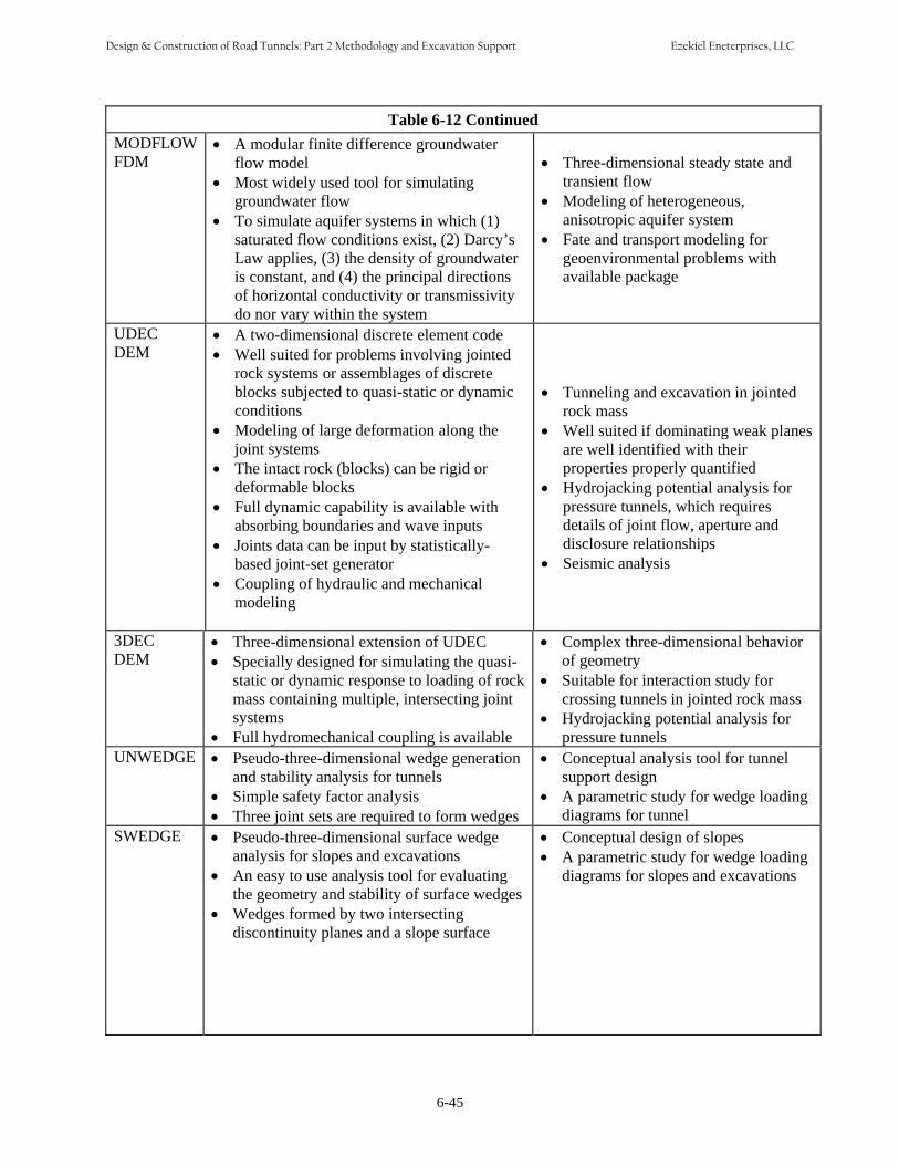
6-45
Table 6-12 Continued MODFLOW • A modular finite difference groundwaterFDM flow model
• Most widely used tool for simulatinggroundwater flow
• To simulate aquifer systems in which (1)saturated flow conditions exist, (2) Darcy’sLaw applies, (3) the density of groundwateris constant, and (4) the principal directionsof horizontal conductivity or transmissivitydo nor vary within the system
• Three-dimensional steady state andtransient flow
• Modeling of heterogeneous,anisotropic aquifer system
• Fate and transport modeling forgeoenvironmental problems withavailable package
UDEC • A two-dimensional discrete element codeDEM • Well suited for problems involving jointed
rock systems or assemblages of discreteblocks subjected to quasi-static or dynamicconditions
• Modeling of large deformation along thejoint systems
• The intact rock (blocks) can be rigid ordeformable blocks
• Full dynamic capability is available withabsorbing boundaries and wave inputs
• Joints data can be input by statistically-based joint-set generator
• Coupling of hydraulic and mechanicalmodeling
• Tunneling and excavation in jointedrock mass
• Well suited if dominating weak planesare well identified with theirproperties properly quantified
• Hydrojacking potential analysis forpressure tunnels, which requiresdetails of joint flow, aperture anddisclosure relationships
• Seismic analysis
3DEC • Three-dimensional extension of UDEC • Complex three-dimensional behaviorDEM • Specially designed for simulating the quasi-
static or dynamic response to loading of rockmass containing multiple, intersecting jointsystems
• Full hydromechanical coupling is available
of geometry• Suitable for interaction study for
crossing tunnels in jointed rock mass• Hydrojacking potential analysis for
pressure tunnelsUNWEDGE • Pseudo-three-dimensional wedge generation
and stability analysis for tunnels• Simple safety factor analysis• Three joint sets are required to form wedges
• Conceptual analysis tool for tunnelsupport design
• A parametric study for wedge loadingdiagrams for tunnel
SWEDGE • Pseudo-three-dimensional surface wedgeanalysis for slopes and excavations
• An easy to use analysis tool for evaluatingthe geometry and stability of surface wedges
• Wedges formed by two intersectingdiscontinuity planes and a slope surface
• Conceptual design of slopes• A parametric study for wedge loading
diagrams for slopes and excavations
Design & Construction of Road Tunnels: Part 2 Methodology and Excavation Support Ezekiel Eneterprises, LLC
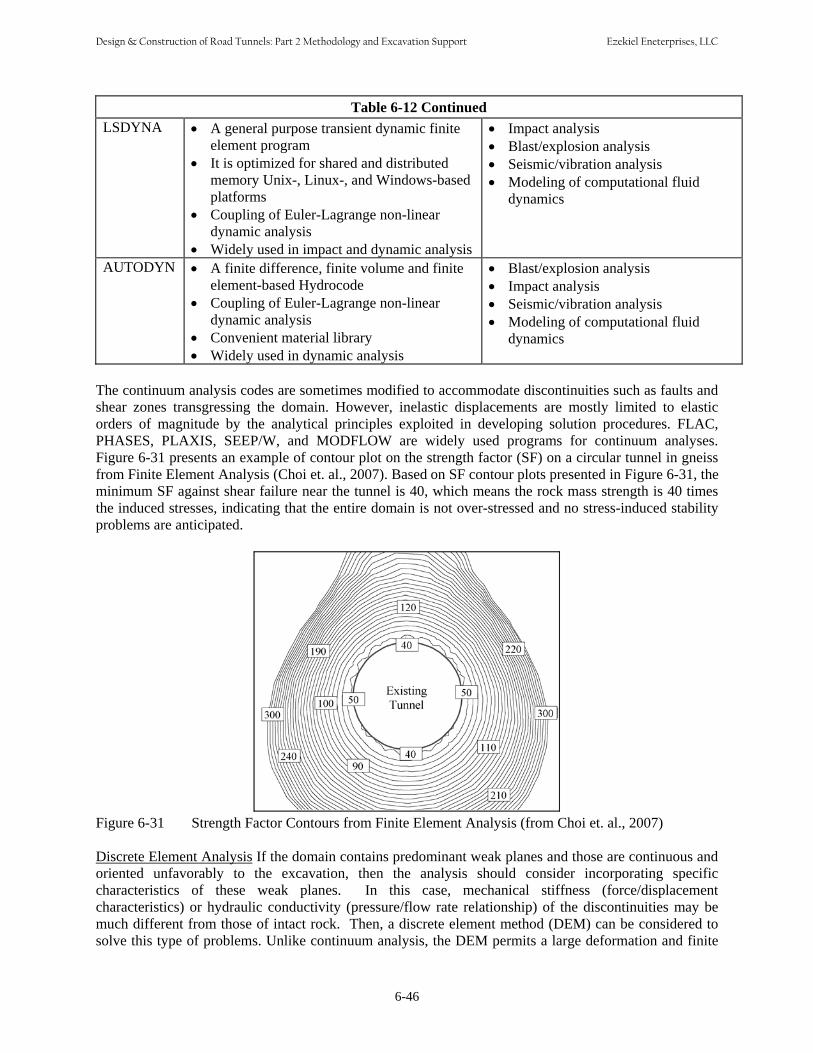
Table 6-12 Continued LSDYNA • A general purpose transient dynamic finite
element program• It is optimized for shared and distributed
memory Unix-, Linux-, and Windows-basedplatforms
• Coupling of Euler-Lagrange non-lineardynamic analysis
• Widely used in impact and dynamic analysis
• Impact analysis• Blast/explosion analysis• Seismic/vibration analysis• Modeling of computational fluid
dynamics
AUTODYN • A finite difference, finite volume and finiteelement-based Hydrocode
• Coupling of Euler-Lagrange non-lineardynamic analysis
• Convenient material library• Widely used in dynamic analysis
• Blast/explosion analysis• Impact analysis• Seismic/vibration analysis• Modeling of computational fluid
dynamics
The continuum analysis codes are sometimes modified to accommodate discontinuities such as faults and shear zones transgressing the domain. However, inelastic displacements are mostly limited to elastic orders of magnitude by the analytical principles exploited in developing solution procedures. FLAC, PHASES, PLAXIS, SEEP/W, and MODFLOW are widely used programs for continuum analyses. Figure 6-31 presents an example of contour plot on the strength factor (SF) on a circular tunnel in gneiss from Finite Element Analysis (Choi et. al., 2007). Based on SF contour plots presented in Figure 6-31, the minimum SF against shear failure near the tunnel is 40, which means the rock mass strength is 40 times the induced stresses, indicating that the entire domain is not over-stressed and no stress-induced stability problems are anticipated.
Figure 6-31 Strength Factor Contours from Finite Element Analysis (from Choi et. al., 2007)
Discrete Element Analysis If the domain contains predominant weak planes and those are continuous and oriented unfavorably to the excavation, then the analysis should consider incorporating specific characteristics of these weak planes. In this case, mechanical stiffness (force/displacement characteristics) or hydraulic conductivity (pressure/flow rate relationship) of the discontinuities may be much different from those of intact rock. Then, a discrete element method (DEM) can be considered to solve this type of problems. Unlike continuum analysis, the DEM permits a large deformation and finite
6-46
Design & Construction of Road Tunnels: Part 2 Methodology and Excavation Support Ezekiel Eneterprises, LLC
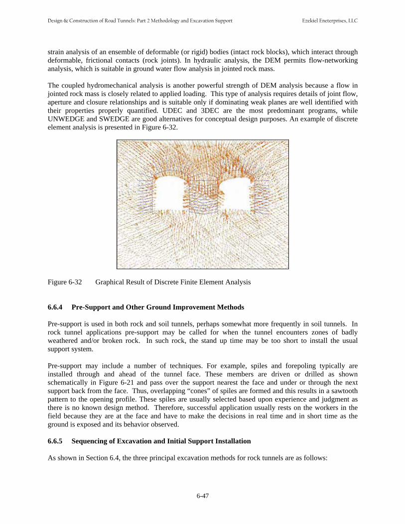
strain analysis of an ensemble of deformable (or rigid) bodies (intact rock blocks), which interact through deformable, frictional contacts (rock joints). In hydraulic analysis, the DEM permits flow-networking analysis, which is suitable in ground water flow analysis in jointed rock mass.
The coupled hydromechanical analysis is another powerful strength of DEM analysis because a flow in jointed rock mass is closely related to applied loading. This type of analysis requires details of joint flow, aperture and closure relationships and is suitable only if dominating weak planes are well identified with their properties properly quantified. UDEC and 3DEC are the most predominant programs, while UNWEDGE and SWEDGE are good alternatives for conceptual design purposes. An example of discrete element analysis is presented in Figure 6-32.
Figure 6-32 Graphical Result of Discrete Finite Element Analysis
6.6.4 Pre-Support and Other Ground Improvement Methods Pre-support is used in both rock and soil tunnels, perhaps somewhat more frequently in soil tunnels. In rock tunnel applications pre-support may be called for when the tunnel encounters zones of badly weathered and/or broken rock. In such rock, the stand up time may be too short to install the usual support system. Pre-support may include a number of techniques. For example, spiles and forepoling typically are installed through and ahead of the tunnel face. These members are driven or drilled as shown schematically in Figure 6-21 and pass over the support nearest the face and under or through the next support back from the face. Thus, overlapping “cones” of spiles are formed and this results in a sawtooth pattern to the opening profile. These spiles are usually selected based upon experience and judgment as there is no known design method. Therefore, successful application usually rests on the workers in the field because they are at the face and have to make the decisions in real time and in short time as the ground is exposed and its behavior observed. 6.6.5 Sequencing of Excavation and Initial Support Installation As shown in Section 6.4, the three principal excavation methods for rock tunnels are as follows:
6-47
Design & Construction of Road Tunnels: Part 2 Methodology and Excavation Support Ezekiel Eneterprises, LLC

• Drill and blast (including SEM/NATM) for full face or multiple heading advance of any shape in any rock.
• Roadheader for full face or multiple heading advance of a shape in rock up to moderate strength.• TBM for full face (generally round only) in any rock. When an excavation is made in intact rock by any method there is an adjustment (or redistribution) in the stresses and strains around that excavation. This adjustment, however, quickly dissipates such that the change is only about six percent at a clear distance of three radii from the wall of the opening. The insitu stresses in the rock are generally low for most highway tunnels because those tunnels are at relatively shallow depth. Thus, in intact rock the (“elastic”) stresses resulting from this redistribution do not exceed the rock strength so stability is not a concern. However, rock in reality is a jointed (blocky) material and it is the behavior of a blocky mass that nearly always governs the behavior of the tunnel. Evert Hoek describes this behavior as follows (Hoek, 2000): “In tunnels excavated in jointed rock mass at relatively shallow depth, the most common types of failure are those involving wedges falling from the roof or sliding out of the sidewalls of the openings. These wedges are formed by intersecting structural features, such as bedding planes and joints, which separate the rock mass into discrete but interlocked pieces. When a free face is created by the excavation of the opening, the restraint from the surrounding rock is removed. One or more of these wedges can fall or slide from the surface if the bounding planes are continuous or rock bridges along the discontinuities are broken. Unless steps are taken to support these loose wedges, the stability of the back and walls of the opening may deteriorate rapidly. Each wedge, which is allowed to fall or slide, will cause a reduction in the restraint and the interlocking of the rock mass and this, in turn, will allow other wedges to fall. This failure process will continue until natural arching in the rock mass prevents further unraveling or until the opening is full of fallen material. The steps which are required to deal with this problem are: Step 1: Determination of average dip and dip direction of significant discontinuity sets. Step 2: Identification of potential wedges which can slide or fall from the back or walls. Step 3: Calculation of the factor of safety of these wedges, depending upon the mode of failure. Step 4: Calculation of the amount of reinforcement required to bring the factor of safety of individual wedges up to an acceptable level.” The concepts for and applications of sequencing of excavation and initial support installation are generally based on drill and blast excavation, but also apply to roadheader excavation. These concepts can be summarized in “one sentence” as follows: do not excavate more than can be quickly removed and quickly supported so that ground control is never compromised. 6.6.6 Face Stability In general, face stability is not as great a concern in rock tunnels as in soil tunnels because the rock stresses tend to arch to the sides and ahead of the face. However, in low strength rock, in areas where the rock is broken up or where the rock is extremely weathered face stability may be an issue. As discussed in Chapter 7 and in Section 6.6.5 the secret to successful tunneling where face stability may be an issue is to assure that individual headings are never so large that they cannot be quickly excavated and quickly supported. In addition, where groundwater exists it should be drawn down or otherwise controlled because, as noted by Terzaghi, unstable ground is usually associated with or aggravated by groundwater under pressure.
6-48
Design & Construction of Road Tunnels: Part 2 Methodology and Excavation Support Ezekiel Eneterprises, LLC

6.6.7 Surface Support
Surface support in a rock tunnel may be supplied by ribs and lagging as discussed above, or, more frequently now, by shotcrete in combination with rock bolts or dowels, steel sets, lattice girders, wire mesh or various types of reinforcement mats. For the most part modern rock tunnels are supported by shotcrete and either rock bolts or lattice girders.
Either system provides a flexible support that takes advantage of the inherent rock strength but that can be stiffened simply and quickly by adding bolts, lattice girders and/or shotcrete. In addition, lattice girders provide a simple template by which to judge the thickness of shotcrete. For other situations wire mesh or reinforcement mats have proven to successfully arrest and hold local raveling until sufficient shotcrete can be applied to knot the whole system together and hold it until the shotcrete attains its strength.
6.6.8 Ground Displacements
For the most part, ground displacements around a rock tunnel can be estimated from elastic theory or calculated using any of a number of computer programs. Elastic theory allows an approximate calculation of the ground displacements around a round tunnel in rock, as shown in Figure 6-33. The approximate radial displacement at a point directly around a tunnel in elastic rock is given by:
P (1+ν ) a2
u = z 6-8E r
Where:
u = Radial movement, in. Pz = Stress in the ground ν = Poisson’s ratio E = Rock mass modules a = Radius of opening r = Radius to point of interest as presented in Figure 6-33.
Figure 6-33 Elastic Approximation of Ground Displacements around a Circular Tunnel in Rock
For any shape other than circular, one can usually sketch a circle that most nearly approximates the true opening and use the radius of that circle in the above solution for an approximate displacement. However, in the rare case where the precise value of movement might be a concern, then it should be determined by numerical analysis. Displacement contours induced by two tunnel excavation, calculated by Finite Element Method, are presented in Figure 6-34.
6-49
Design & Construction of Road Tunnels: Part 2 Methodology and Excavation Support Ezekiel Eneterprises, LLC

000,-0,-66..55 0.66 0.0000,,--6.6. 0.005656 0.00,,-- 0.2.192.19 0.00,00,--2.2. 0.1919 0.0000,,--2.2. 0.1919 0.0000,,--2.2. 0.001919 0.00,,-- 0.2.192.19 0.00,00,--2.2. 0.1919 0.0000,,--2.2. 0.001919 0.00,-,-22..11 0.0099 0.00,,-- 0.2.192.19 0.00,00,--6.6.5656 FF FF FF FF FF FF FF FF FF FF FF FF
0.001 0.0015
0.0015 0.002
0.001
0.00225
0.00075
0.0005 0.0005
0.00025
0.001
0.00025 0.0025
0.00150.002
Figure 6-34 Ground Displacement Contours Calculated by Finite Element Method
6.7 GROUNDWATER CONTROL DURING EXCAVATION Groundwater control in rock can take many forms depending on the nature and extent of the problem. In fact, for many cases experience has proven that a combination of control methods may be the best solution. For a given tunnel it may also be found that different solutions apply at different locations along the alignment. 6.7.1 Dewatering at the Tunnel Face Dewatering at the tunnel face is the most common method of groundwater control. This consists simply of allowing the water to drain into the tunnel through the face, collecting the water, and taking it to the rear by channels or by pumping. It then joins the site water disposal system. Note that if there are hydraulic or other leaks or spills at the TBM or other equipment in the tunnel such contaminants are in this water. 6.7.2 Drainage Ahead of Face from Probe Holes Probe holes ahead of the tunnel may be placed to verify the characteristics of the rock and hence to provide information for machine operation and control. These holes will also predrain the rock and provide warning of (and drain) any methane, hydrogen sulfide or any other gas, petroleum, or contaminant that may be present. In areas where there are such known deposits of gas or other contaminants it is common (and recommended) practice to keep one or more probe holes out in front of the machine. When such materials are encountered, the probes alert the workers to the need to increase the frequency of gas readings, to increase the volume of ventilation or to take other steps as required to avoid the problem of unexpected or excessive gas in the tunnel. 6.7.3 Drainage from Pilot Bore/Tunnel Pilot tunnels can provide a number of benefits to a larger tunnel drive, including: • Groundwater drainage• Gas or other contaminant drainage
6-50
Design & Construction of Road Tunnels: Part 2 Methodology and Excavation Support Ezekiel Eneterprises, LLC
• Exploratory information on the geology • Grouting or bolting galleries for pre-support of a larger opening • Rock behavior/loading information for design of the larger opening The question of location and size of pilot tunnel always leads to a spirited discussion such that no two are ever the same. They are typically six to eight feet in general size and may be located at one or more of several locations. As one example, on the H-3 project in Hawaii there was concern that huge volumes of water might be encountered. This is a 36 ft + highway through the mountain to the opposite side of the island. Borings were limited, but did not indicate huge volumes of water. However it was common knowledge that similar sites contained water-filled cavities large enough for canoe navigation and there was concern that a similarly large volume would be found in the H-3 tunnel. The pilot tunnel, proved that water was not a major concern and at the same time provided a second, unexpected benefit: by being able to see and analyze the rock for the whole tunnel bore, the winning contractor determined that he could perform major parts of the excavation by ripping with state-of-the-art large rippers in lieu of using drill and blast techniques. Because of this evaluation he was able to shave off millions of dollars in his bid and accelerate the construction schedule by several weeks. As an added benefit, the pilot tunnel was enlarged slightly and now is the permanent access (by way of special drifts) for maintenance forces to access the entire length of tunnel with small pickups without using the active traffic lanes. 6.7.4 Grouting Groundwater inflow into rock tunnels almost exclusively comes in at joints, bedding planes, shears, fault zones and other fractures. Because these can be identified grouting is the most commonly used method of groundwater control. A number of different grout materials are used depending on the size of the opening and the amount of the inflow. The design approach is first to detect zones of potentially high groundwater inflow by drilling probe holes out in front of the tunnel face. Second, the zones are characterized and, hopefully, the major water carrying joints tentatively defined. Then, third, a series of grout holes are drilled out to intercept those joints 10 feet to a tunnel diameter beyond the tunnel face or wall. Fourth, using tube-a-machetes, cement and/or water reactive grouts are injected to seal off the water to a level such that succeeding holes are drilled as the fifth step and injected with finer, more penetrating grouts such as micro-fine or ultra-fine cements and/or sodium silicate can be injected to complete the sealing off process. Based on evaluation of the grouting success additional holes and grouting may be required to finally reduce the inflow to an acceptable level. Typically it will be found that steps four and five must be repeated, trial and error, until the required reduction in flow is achieved. 6.7.5 Freezing On rare occasions, it may become necessary to try freezing for groundwater control in a tunnel in rock. This might occur, for example, at a shaft where it was necessary to control the groundwater locally for a breakout of a TBM into the surrounding rock. If upon beginning excavation of the TBM launch chamber it were found that the water inflow was too great the alternative control methods would be to grout as discussed above or perhaps to freeze. The authors are not aware of any examples in the U.S. where freezing has been used in a rock tunnel, probably for a very simple reason that high inflow encountered into a rock tunnel would be concentrated at the joints present in the rock. The concentration would usually result in a relatively high velocity of flow. Such velocity would typically exceed six feet per day, the maximum groundwater velocity for which it is feasible to perform effective freezing. Thus, for the most part freezing would not be used in
6-51
Design & Construction of Road Tunnels: Part 2 Methodology and Excavation Support Ezekiel Eneterprises, LLC
rock tunneling except very locally, as discussed above, and even then it might be necessary to use liquid nitrogen to perform the freezing. 6.7.6 Closed Face Machine A closed face machine could be used for rock tunneling in high groundwater flow conditions over short lengths. In reality such a machine would be more like an earth pressure balance (EPB) machine with sufficient rock cutters installed to excavate the rock. For any extended length (greater than a few hundred feet) this would typically be uneconomical. The machine would have to grind up the rock cuttings and mix, the resulting “fines” with large quantities of conditioners and the existing water to result in a plastic material. This is necessary for the EPB to control the face in front of the bulkhead and to bring the material from its pressurized state at the face down to ambient by means of the EPB screw conveyor (See Chapter 7). For these reasons, one would not normally plan to build a closed face rock machine but to equip an EPB with rock cutters for driving short stretches in rock within a longer soft ground tunnel. An exception to this general statement would be a rock tunnel in weak or soft rock such as chalk, marl, shale, or sandstone of quite low strength such that it essentially behaved as high strength soft ground. 6.7.7 Other Measures of Groundwater Control The groundwater control methods discussed above probably account for more than 95% of the cases where such control is required in a tunnel in rock. For the odd tunnel (or shaft) where something else is required the designer may have to rely on experience and or ingenuity to come up with the solution. A few suggestions are given here, but really inventive solutions may have to be developed on a case-by-case basis. Compressed Air once was a mainstay for control of groundwater or flowing or squeezing ground conditions but it is used very infrequently in modern construction. Where the tunnel (or shaft) can be stabilized by relatively low pressures (say 10 psi or less) it may still be used. However, it requires compressor plants, locks, special medical emergency preparation and decompression times. Panning may be attractive in some cases where the water inflow is not too excessive and is concentrated at specific points and/or seams. In this case pans are placed over the leaks and shotcreted into place. Water is carried in chases or tubes to the invert and dumped into the tunnel drainage system Drainage Fabric is now frequently used in rock tunnels. These geotechnical fabrics can be put in over the whole tunnel circumference or, more often, in strips on a set pattern or where the leaks are occurring. Fastened to the surface of the rock with the waterproof membrane portion facing into the tunnel, this fabric is then sandwiched in place by the cast-in-place concrete lining. The fibrous portion of the fabric provides a drainage pathway around and down the tunnel walls and into a collection system at the tunnel invert. 6.8 PERMANENT LINING DESIGN ISSUES 6.8.1 Introduction For many tunnels the principle purpose of the final lining is to prepare the tunnel for its end use, for example, to improve its aesthetics for people or its flow characteristics for water conveyance. Thus, the final lining may consist of cast-in-place concrete, precast concrete panels, or shotcrete.
6-52
Design & Construction of Road Tunnels: Part 2 Methodology and Excavation Support Ezekiel Eneterprises, LLC
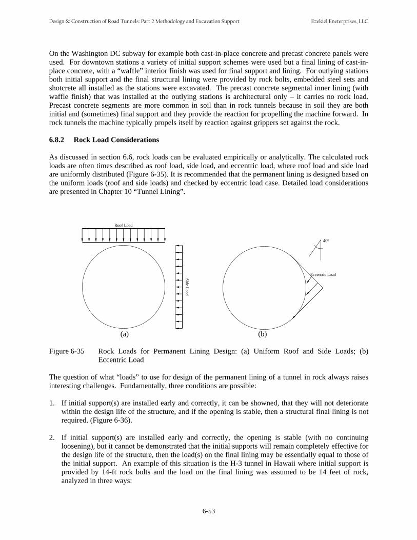
On the Washington DC subway for example both cast-in-place concrete and precast concrete panels were used. For downtown stations a variety of initial support schemes were used but a final lining of cast-inplace concrete, with a “waffle” interior finish was used for final support and lining. For outlying stations both initial support and the final structural lining were provided by rock bolts, embedded steel sets and shotcrete all installed as the stations were excavated. The precast concrete segmental inner lining (with waffle finish) that was installed at the outlying stations is architectural only – it carries no rock load. Precast concrete segments are more common in soil than in rock tunnels because in soil they are both initial and (sometimes) final support and they provide the reaction for propelling the machine forward. In rock tunnels the machine typically propels itself by reaction against grippers set against the rock.
6.8.2 Rock Load Considerations
As discussed in section 6.6, rock loads can be evaluated empirically or analytically. The calculated rock loads are often times described as roof load, side load, and eccentric load, where roof load and side load are uniformly distributed (Figure 6-35). It is recommended that the permanent lining is designed based on the uniform loads (roof and side loads) and checked by eccentric load case. Detailed load considerations are presented in Chapter 10 “Tunnel Lining”.
Roof Load Side Load
Eccentric Load
40°
(a) (b)
Figure 6-35 Rock Loads for Permanent Lining Design: (a) Uniform Roof and Side Loads; (b) Eccentric Load
The question of what “loads” to use for design of the permanent lining of a tunnel in rock always raises interesting challenges. Fundamentally, three conditions are possible: 1. If initial support(s) are installed early and correctly, it can be showned, that they will not deteriorate
within the design life of the structure, and if the opening is stable, then a structural final lining is not required. (Figure 6-36).
2. If initial support(s) are installed early and correctly, the opening is stable (with no continuingloosening), but it cannot be demonstrated that the initial supports will remain completely effective forthe design life of the structure, then the load(s) on the final lining may be essentially equal to those of the initial support. An example of this situation is the H-3 tunnel in Hawaii where initial support is provided by 14-ft rock bolts and the load on the final lining was assumed to be 14 feet of rock, analyzed in three ways:
6-53
Design & Construction of Road Tunnels: Part 2 Methodology and Excavation Support Ezekiel Eneterprises, LLC

Figure 6-36 Unlined Rock Tunnel in Zion National Park, Utah
• Uniform load across the entire tunnel width• Uniform load across half of the tunnel width• Triangular load across the entire tunnel width with the maximum at the centerline.
3. If initial support(s) are providing a seemingly stable opening but it is known that additional support is
required for long term stability then that support must be provided by the final lining. An example ofthis situation is the Superconducting Super Collider where tunnels in chalk were initially stabilized by pattern rock bolts in the crown and spot bolts elsewhere. Months later, however, slaking (and perhapscreep) resulted in linear wedges (with dimensions up to approximately by one-third the tunnel diameter) “working” and sometimes falling into tunnels driven and supported months earlier. To be stable long-term, a lining or additional permanent rock bolts capable of supporting these wedges orblocks would have been necessary.
As illustrated by the above, determination of the requirement for and value of “loads” to be used for
design of final linings in tunnels cannot be prescribed in the manner that is possible for structuralbeams and columns. Rather, the vagaries of nature must be understood and applied by all on thedesign and construction team.
6.8.3 Groundwater Load Considerations For conventional tunnels, the groundwater table is lowered by tunnel excavation, because the tunnels act as a drain. When the undrained system is considered, the groundwater lowering measures are disrupted after the final lining is placed and the groundwater table will reestablish its original position. For a
6-54
Design & Construction of Road Tunnels: Part 2 Methodology and Excavation Support Ezekiel Eneterprises, LLC
drained system, the groundwater is lowered and will lowered so long as rainfall or at the project site seepage is not sufficient to raise the groundwater table. For underwater tunnels, the groundwater table keeps constant due to the water body above the tunnels and full hydrostatic water pressure should be considered with an undrained system unless an intensive grouting program is implemented in the surrounding ground. This section discusses factors affecting groundwater flow regime and interaction with concrete lining, and methods to estimate groundwater loadings in the lining design including empirical method, analytical solution, and numerical method. 6.8.3.1 Factors on the Lining Loads due to Water Flow Groundwater loadings on the underwater tunnel linings can be reduced with a drained system while the groundwater table keeps constant. The main factors that affect water loads on the underwater tunnel linings due to water flow are: (1) relative ground-lining permeability; (2) relative ground-lining stiffness; and (3) geometric factors such as depth below the water body. The water loads on the lining are greatly dependent on the relative permeability between the lining and surrounding ground. For a tunnel where the lining has a relatively low permeability when compared to the surrounding ground, the lining will behave almost as impermeable and almost no head will be lost in the surrounding ground resulting in hydrostatic water pressures applied directly on the lining. A relatively permeable lining, on the other hand, will behave as a drain and almost no head will be lost when the water flows through the lining and no direct loads will act on the lining. The loads due to the groundwater will only act on the lining indirectly through the loads applied by the seepage force onto the surrounding ground. The influence of the relative stiffness is well visualized for the tunnels in a stiff rock mass, where the linings are not designed for the full hydrostatic water pressures by using drained systems. For tunnels in soft ground, the linings are normally designed to withstand a full hydrostatic load. 6.8.3.2 Empirical Groundwater Loads The empirical groundwater loading conditions used for the design of tunnel linings in New York are shown in Figure 6-37 and are based on empirical data. As indicated in Figure 6-37, the groundwater loading diagram follows hydrostatic pressure to a maximum near the tunnel springline (head of Hs), is held constant over a sidewall area of 1/3Hsw, then decreases to 10 percent of hydrostatic pressure at the invert (0.1Hw). The empirical loads shown in Figure 6-37 are based on the assumptions that the drainage system is to be comprised of a wall drainage layer (filter fabric), invert drainage collector pipes placed behind the wall and below the cavern floor, and a drainage blanket developed by covering the entire invert with a gravel layer. The water load at the invert level is reduced to 10 percent of hydrostatic water pressure at the invert level with a well-sized and designed gravel drainage bed and drain pipe(s) in the invert (including appropriate provisions and follow up actions for long term maintenance). Under other circumstances, 25 percent of hydrostatic water pressure is recommended at the invert level. The empirical loads are probably conservative but address concerns that groundwater percolating through the wall rock over time could possibly clog the drainage layer (fabric) placed outside the concrete wall causing a buildup of groundwater pressure beyond that assumed under the assumption that the thick invert drainage blanket and collector drains should continue to function.
6-55
Design & Construction of Road Tunnels: Part 2 Methodology and Excavation Support Ezekiel Eneterprises, LLC
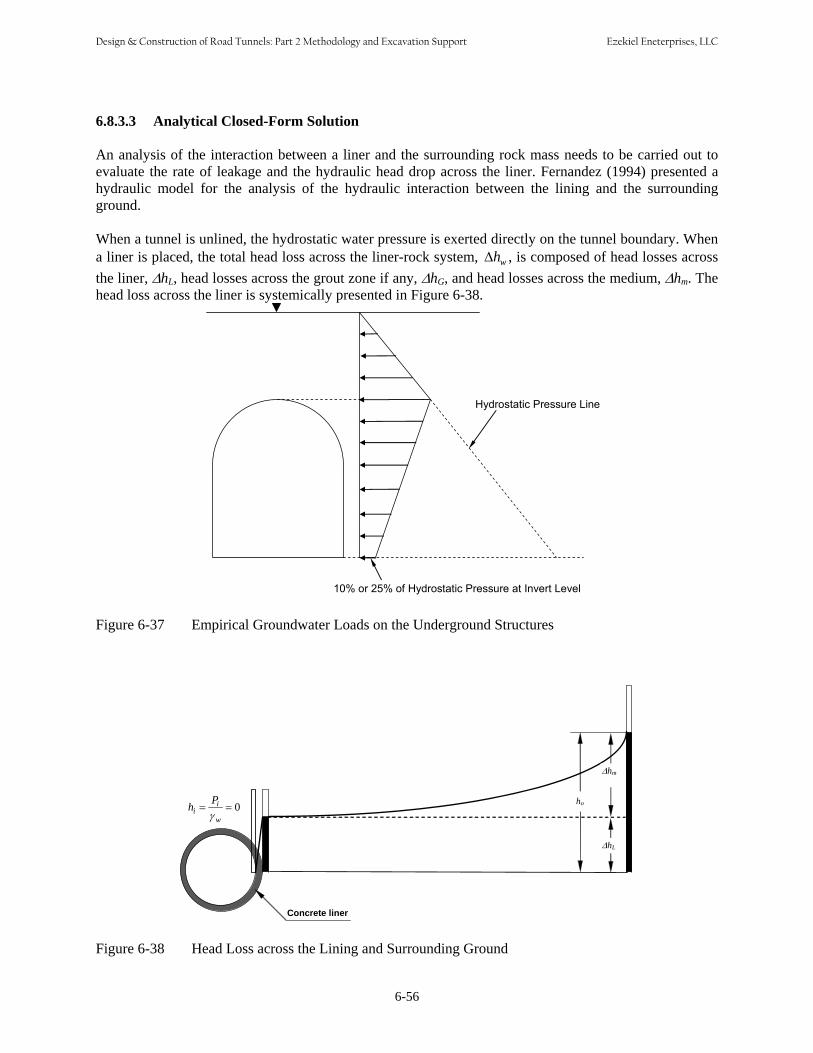
6.8.3.3 Analytical Closed-Form Solution An analysis of the interaction between a liner and the surrounding rock mass needs to be carried out to evaluate the rate of leakage and the hydraulic head drop across the liner. Fernandez (1994) presented a hydraulic model for the analysis of the hydraulic interaction between the lining and the surrounding ground. When a tunnel is unlined, the hydrostatic water pressure is exerted directly on the tunnel boundary. When a liner is placed, the total head loss across the liner-rock system, Δhw , is composed of head losses across the liner, ΔhL, head losses across the grout zone if any, ΔhG, and head losses across the medium, Δhm. The head loss across the liner is systemically presented in Figure 6-38.
Hydrostatic Pressure Line
10% or 25% of Hydrostatic Pressure at Invert Level
Figure 6-37 Empirical Groundwater Loads on the Underground Structures
Pih = = 0i γ w
ΔhL
ho
Δhm
Concrete liner
Figure 6-38 Head Loss across the Lining and Surrounding Ground
6-56
Design & Construction of Road Tunnels: Part 2 Methodology and Excavation Support Ezekiel Eneterprises, LLC
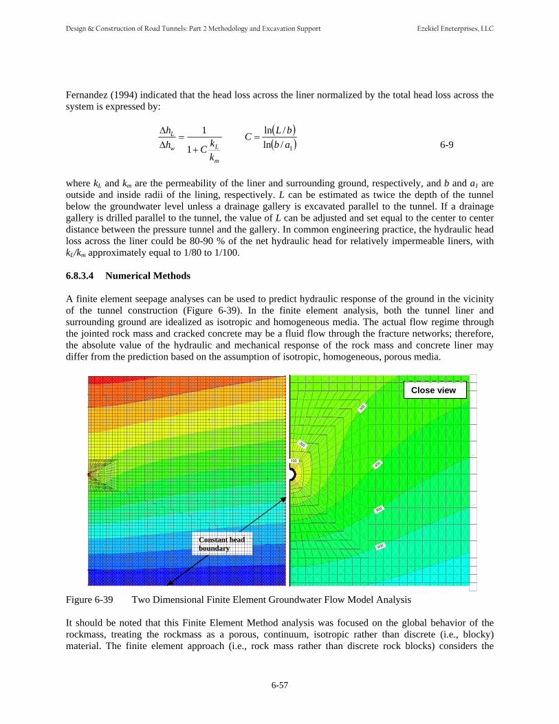
Fernandez (1994) indicated that the head loss across the liner normalized by the total head loss across the system is expressed by:
m
Lw
L
kkCh
h
+=
ΔΔ
1
1 ( )( )1/ln
/lnabbLC =
6-9
where kL and km are the permeability of the liner and surrounding ground, respectively, and b and a1 are outside and inside radii of the lining, respectively. L can be estimated as twice the depth of the tunnel below the groundwater level unless a drainage gallery is excavated parallel to the tunnel. If a drainage gallery is drilled parallel to the tunnel, the value of L can be adjusted and set equal to the center to center distance between the pressure tunnel and the gallery. In common engineering practice, the hydraulic head loss across the liner could be 80-90 % of the net hydraulic head for relatively impermeable liners, with kL/km approximately equal to 1/80 to 1/100.
6.8.3.4 Numerical Methods
A finite element seepage analyses can be used to predict hydraulic response of the ground in the vicinity of the tunnel construction (Figure 6-39). In the finite element analysis, both the tunnel liner and surrounding ground are idealized as isotropic and homogeneous media. The actual flow regime through the jointed rock mass and cracked concrete may be a fluid flow through the fracture networks; therefore, the absolute value of the hydraulic and mechanical response of the rock mass and concrete liner may differ from the prediction based on the assumption of isotropic, homogeneous, porous media.
100
200
300
400
500
600
Close view
Constant head boundary
Figure 6-39 Two Dimensional Finite Element Groundwater Flow Model Analysis
It should be noted that this Finite Element Method analysis was focused on the global behavior of the rockmass, treating the rockmass as a porous, continuum, isotropic rather than discrete (i.e., blocky) material. The finite element approach (i.e., rock mass rather than discrete rock blocks) considers the
6-57
Design & Construction of Road Tunnels: Part 2 Methodology and Excavation Support Ezekiel Eneterprises, LLC

equivalent rockmass permeability, where the effects of hydraulic characteristics of fluid flow through rock joints are accounted for and approximated by the equivalent rockmass permeability. This approach has been used frequently for groundwater flow problems in the field of tunnel engineering. However, estimating the equivalent rock mass permeability closer than an order of magnitude is a great challenge and certainly requires special attention.
Use of discrete element analysis is sometimes very difficult because it requires detailed input parameters of the rock joints such as joint attitudes, joint spacing, joint connectivity, hydraulic apertures of the joints, normal and shear stiffness. Coupling effect of the mechanical and hydraulic behavior of rock joints also requires understanding of the relationship between mechanical closure and hydraulic aperture of the joints. Without proper input parameters, the results from the discrete element analysis would not be reliable.
6.8.4 Drained Versus Undrained System
Drained Waterproofing System Drained waterproofing systems reduce hydrostatic loads on structures, enabling thinner and more lightly reinforced liners to be designed. In a fractured rock mass, high groundwater inflows often enter drained systems (even after rock mass grouting) resulting in increased pumping costs. High inflows can also increase the deposition of calcium precipitate in pipes. Under these conditions, an undrained system may be more efficient.
In the drained waterproof systems, the pipes and drainage layers are required to remain open and flowing to prevent the build-up of hydrostatic pressures. Regular inspections and maintenance of the drainage system are required to prevent hydrostatic loads rising to a level that could exceed the capacity of the structure. Figure 6-40 presents the cross-sectional layout for typical drained waterproofing system.
Allowable water infiltration rate varies depending upon the purpose of tunnel, tunnel dimension and local environmental law requirements. The rate of allowable infiltration acceptable to the owner shall be as specified in the contract documents. Some owners have used a rate of 1 gallon/minute per 1000 ft of tunnel length. The local infiltration limit is 0.25 gallon per day for 10 square feet of area, and 1 drip per minute at any location.
Figure 6-40 Drained Waterproofing System
6-58
Design & Construction of Road Tunnels: Part 2 Methodology and Excavation Support Ezekiel Eneterprises, LLC
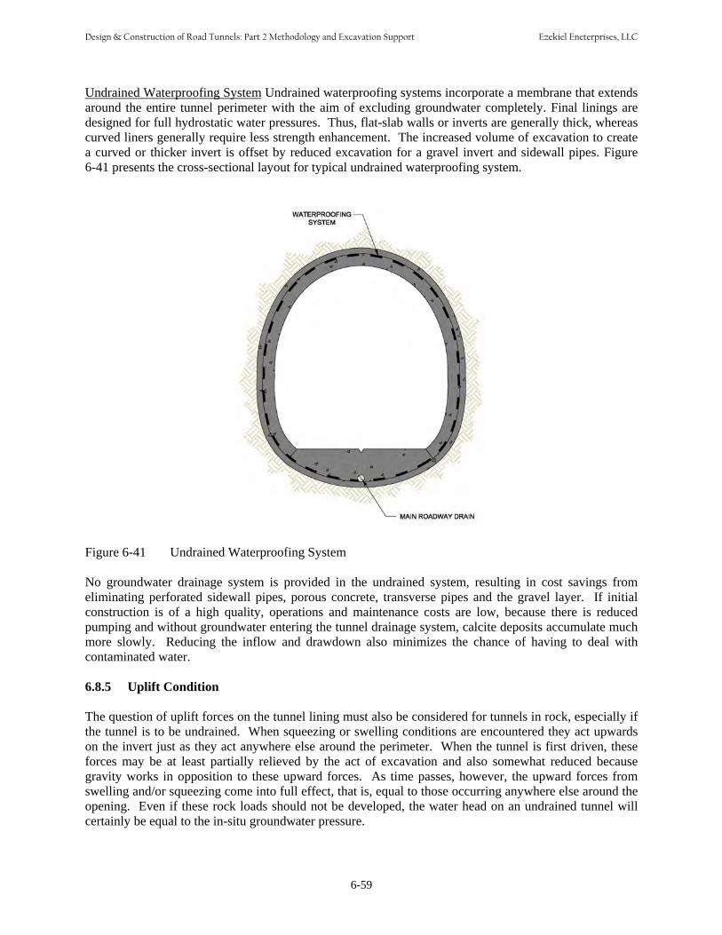
Undrained Waterproofing System Undrained waterproofing systems incorporate a membrane that extends around the entire tunnel perimeter with the aim of excluding groundwater completely. Final linings are designed for full hydrostatic water pressures. Thus, flat-slab walls or inverts are generally thick, whereas curved liners generally require less strength enhancement. The increased volume of excavation to create a curved or thicker invert is offset by reduced excavation for a gravel invert and sidewall pipes. Figure 6-41 presents the cross-sectional layout for typical undrained waterproofing system.
Figure 6-41 Undrained Waterproofing System
No groundwater drainage system is provided in the undrained system, resulting in cost savings from eliminating perforated sidewall pipes, porous concrete, transverse pipes and the gravel layer. If initial construction is of a high quality, operations and maintenance costs are low, because there is reduced pumping and without groundwater entering the tunnel drainage system, calcite deposits accumulate much more slowly. Reducing the inflow and drawdown also minimizes the chance of having to deal with contaminated water. 6.8.5 Uplift Condition The question of uplift forces on the tunnel lining must also be considered for tunnels in rock, especially if the tunnel is to be undrained. When squeezing or swelling conditions are encountered they act upwards on the invert just as they act anywhere else around the perimeter. When the tunnel is first driven, these forces may be at least partially relieved by the act of excavation and also somewhat reduced because gravity works in opposition to these upward forces. As time passes, however, the upward forces from swelling and/or squeezing come into full effect, that is, equal to those occurring anywhere else around the opening. Even if these rock loads should not be developed, the water head on an undrained tunnel will certainly be equal to the in-situ groundwater pressure.
6-59
Design & Construction of Road Tunnels: Part 2 Methodology and Excavation Support Ezekiel Eneterprises, LLC
Whether it is swelling, squeezing, water pressure or any combination thereof the invert of the tunnel will be subjected to upward forces. Typically, this means that the invert should be modified to a curved geometry to react to these upward forces – it is far easier to develop a stable curved structure than it is to permanently stabilize a flat invert. Even without squeezing or swelling the uplift water load can be quite expensive to resist with a flat invert as compared to a curved one. Thus, the most economical solution is usually to go directly to a curved configuration wherein the curved shape (when supported by steel ribs) will carry almost twice the load it will carry with a straight invert or straight sides (Proctor, 1968). 6.8.6 Waterproofing For the most part tunnels in rock are waterproofed by a sandwich consisting of: • A geotechnical drainage fabric that is put in place directly against the rock either continuously or in
strips. This may be held in place by pins or nails driven or shot into the rock.
• Next a continuous waterproof membrane is installed. This membrane may be high densitypolyethylene (HDPE) or polyvinylchloride (PVC) or other similar material. To be continuous themembrane has to be cut and fit to all strange shapes and corners encountered and welded together (by heat) to make a continuous waterproofing membrane within the tunnel. Successful installation isquite dependent upon workmanship in three areas:
o Avoiding puncturing, tearing and the like of the membrane.o Correctly making and testing all joints.o Connecting the waterproof membrane to the wall without introducing leaks.
• Finally a cast in place lining of concrete is placed to hold the sandwich together and to provide the
desired inner surface of the tunnel. Of course, the challenge is to get the concrete placed withoutdamaging the membrane(s), this is especially challenging when the cast in place concrete must be reinforced.
Unlined and partial lined tunnels are common in many short mountainous tunnels in competent rock and stabilized with or without patterned rock bolts on the exposed rock (Figure 6-37). Groundwater inflows are tolerated and collected. See Chapter 16 for groundwater control measures.
6-60
Design & Construction of Road Tunnels: Part 2 Methodology and Excavation Support Ezekiel Eneterprises, LLC

CHAPTER 7 SOFT GROUND TUNNELING
CHAPTER 7 SOFTGROUND TUNNELING
7.1 INTRODUCTION Chapters 6 through 10 present design recommendations and requirements for mined and bored road tunnels. Chapter 7 addresses analysis, design and construction issues specifically for tunneling (mostly shield tunneling) in soft ground including cohesive soils, cohesionless soils and silty sands. Chapter 10 addresses the design of various types of permanent lining applicable for soft ground tunnels. Human kind has been excavating in soft ground for thousands of years. Archeological digs in Europe and elsewhere show that all kinds of tools were used by our ancestors to excavate soil (mostly for “caves” in which to live): bones, antlers, sticks, rocks and the like. However, there are tunnels in Europe that were built by the Romans, are over 2000 years old, and are still in service carrying water. As the population grows and we demand more and more transportation services, there can be no doubt that the requirement for tunnels will also grow. Through it all, the art of tunnel design and construction will also continue to develop, but it is doubtful that this art will ever develop into a science comparable to structural design. The structural engineer can specify both the configuration and the properties in great detail; the tunnel engineer must work with existing materials that cannot be specified and, in addition, are constantly changing, often dramatically. Problematic soft ground conditions such as running sand and very soft clays are discussed in Chapter 8. Mining sequentially through soft ground based on the sequential excavation method (SEM) principles is discussed in Chapter 9. The data needed for analysis and design is discussed in Chapter 3. The results of the analysis and design presented herein are typically presented in the Geotechnical design memorandum (Chapter 4) and form the basis of the Geotechnical Baseline Report (Chapter 4).
7.2 GROUND BEHAVIOR
7.2.1 Soft Ground Classification Anticipated ground behavior in soft ground tunnels was first defined by Terzaghi (1950) by means of the Tunnelman’s Ground Classification (Table 7-1). It can be also be discussed in terms of soil identification (by particle size) and by considering behavior above and below the water table as summarized in the following. Cohesive Soils and Silty Sand Above Water Table Cohesive (clayey) soils behave as a ductile plastic material that moves into the tunnel in a theoretically uniform manner. Following Peck’s (1969) lead for cohesive (clay) materials or materials with sufficient cohesion or cementation to sample and test for unconfined compression strength, an estimate of ground behavior in tunneling can be obtained from the equation:
P − P Ncrit = z a 7-1
S u
Where Ncrit is the stability factor, Pz is the overburden pressure to the tunnel centerline, Pa is the equivalent uniform interior pressure applied to the face (as by breasting or compressed air), and Su is the undrained shear strength (defined for this purpose as one-half of the unconfined compressive strength).
7-1
Design & Construction of Road Tunnels: Part 2 Methodology and Excavation Support Ezekiel Eneterprises, LLC
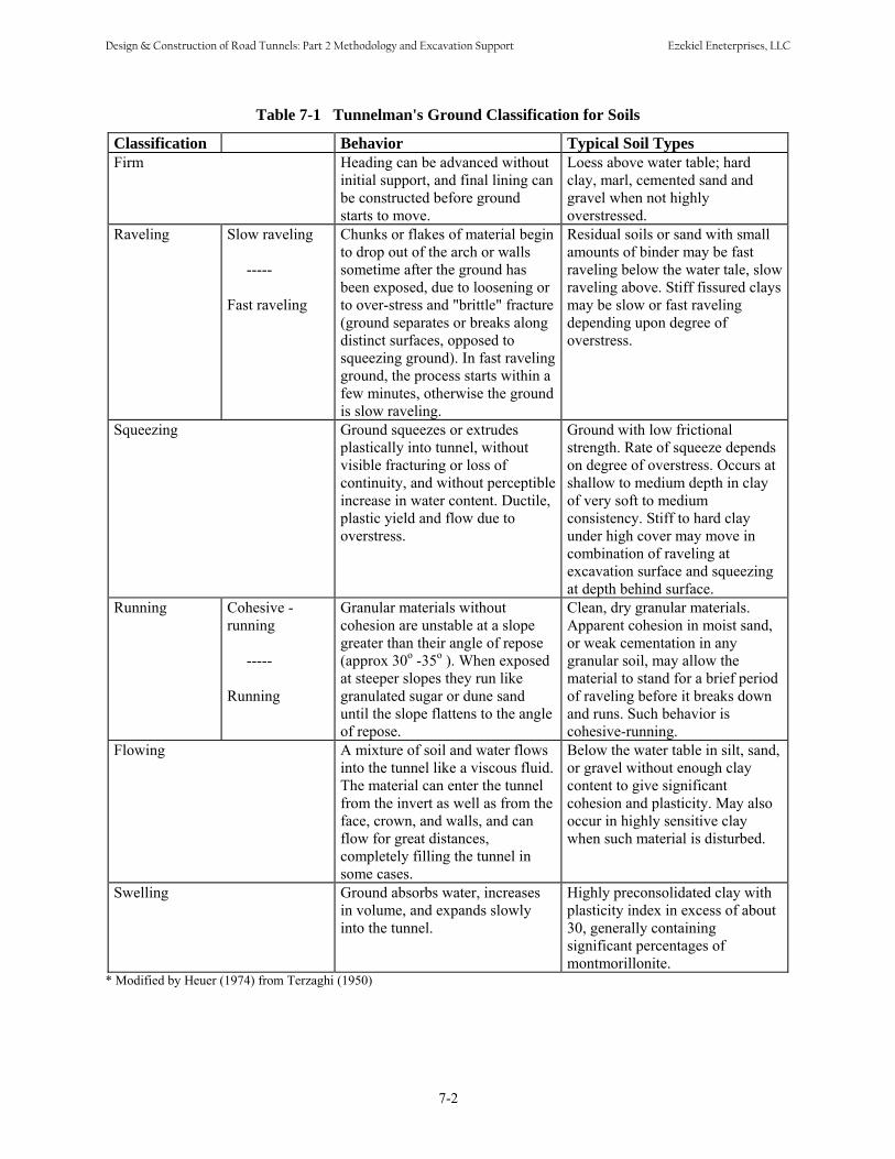
Table 7-1 Tunnelman's Ground Classification for Soils
Classification Behavior Typical Soil Types Firm Heading can be advanced without
initial support, and final lining can be constructed before ground starts to move.
Loess above water table; hard clay, marl, cemented sand and gravel when not highly overstressed.
Raveling Slow raveling
-----
Fast raveling
Chunks or flakes of material begin to drop out of the arch or walls sometime after the ground has been exposed, due to loosening or to over-stress and "brittle" fracture (ground separates or breaks along distinct surfaces, opposed to squeezing ground). In fast raveling ground, the process starts within a few minutes, otherwise the ground is slow raveling.
Residual soils or sand with small amounts of binder may be fast raveling below the water tale, slow raveling above. Stiff fissured clays may be slow or fast raveling depending upon degree of overstress.
Squeezing Ground squeezes or extrudes plastically into tunnel, without visible fracturing or loss of continuity, and without perceptible increase in water content. Ductile, plastic yield and flow due to overstress.
Ground with low frictional strength. Rate of squeeze depends on degree of overstress. Occurs at shallow to medium depth in clay of very soft to medium consistency. Stiff to hard clay under high cover may move in combination of raveling at excavation surface and squeezing at depth behind surface.
Running Cohesive - running
-----
Running
Granular materials without cohesion are unstable at a slope greater than their angle of repose (approx 30o -35o ). When exposed at steeper slopes they run like granulated sugar or dune sand until the slope flattens to the angle of repose.
Clean, dry granular materials. Apparent cohesion in moist sand, or weak cementation in any granular soil, may allow the material to stand for a brief period of raveling before it breaks down and runs. Such behavior is cohesive-running.
Flowing A mixture of soil and water flows into the tunnel like a viscous fluid. The material can enter the tunnel from the invert as well as from the face, crown, and walls, and can flow for great distances, completely filling the tunnel in some cases.
Below the water table in silt, sand, or gravel without enough clay content to give significant cohesion and plasticity. May also occur in highly sensitive clay when such material is disturbed.
Swelling Ground absorbs water, increases in volume, and expands slowly into the tunnel.
Highly preconsolidated clay with plasticity index in excess of about 30, generally containing significant percentages of montmorillonite.
* Modified by Heuer (1974) from Terzaghi (1950)
7-2
Design & Construction of Road Tunnels: Part 2 Methodology and Excavation Support Ezekiel Eneterprises, LLC
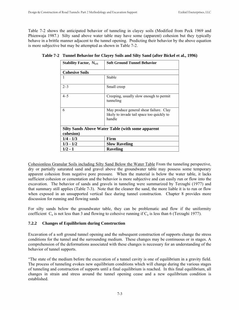
Table 7-2 shows the anticipated behavior of tunneling in clayey soils (Modified from Peck 1969 and Phienwaja 1987.) Silty sand above water table may have some (apparent) cohesion but they typically behave in a brittle manner adjacent to the tunnel opening. Predicting their behavior by the above equation is more subjective but may be attempted as shown in Table 7-2.
Table 7-2 Tunnel Behavior for Clayey Soils and Silty Sand (after Bickel et al., 1996)
Stability Factor, Ncrit Soft Ground Tunnel Behavior
Cohesive Soils 1 Stable
2–3 Small creep
4–5 Creeping, usually slow enough to permit tunneling
6 May produce general shear failure. Clay likely to invade tail space too quickly to handle
Silty Sands Above Water Table (with some apparent cohesion) 1/4 - 1/3 Firm 1/3 - 1/2 Slow Raveling 1/2 - 1 Raveling
Cohesionless Granular Soils including Silty Sand Below the Water Table From the tunneling perspective, dry or partially saturated sand and gravel above the groundwater table may possess some temporary apparent cohesion from negative pore pressure. When the material is below the water table, it lacks sufficient cohesion or cementation and the behavior is more subjective and can easily run or flow into the excavation. The behavior of sands and gravels in tunneling were summarized by Terzaghi (1977) and that summary still applies (Table 7-3). Note that the cleaner the sand, the more liable it is to run or flow when exposed in an unsupported vertical face during tunnel construction. Chapter 8 provides more discussion for running and flowing sands For silty sands below the groundwater table, they can be problematic and flow if the uniformity coefficient Cu is not less than 3 and flowing to cohesive running if Cu is less than 6 (Terzaghi 1977).
7.2.2 Changes of Equilibrium during Construction Excavation of a soft ground tunnel opening and the subsequent construction of supports change the stress conditions for the tunnel and the surrounding medium. These changes may be continuous or in stages. A comprehension of the deformations associated with these changes is necessary for an understanding of the behavior of tunnel supports. “The state of the medium before the excavation of a tunnel cavity is one of equilibrium in a gravity field. The process of tunneling evokes new equilibrium conditions which will change during the various stages of tunneling and construction of supports until a final equilibrium is reached. In this final equilibrium, all changes in strain and stress around the tunnel opening cease and a new equilibrium condition is established.
7-3
Design & Construction of Road Tunnels: Part 2 Methodology and Excavation Support Ezekiel Eneterprises, LLC

Table 7-3 Tunnel Behavior: Sands and Gravels
Designation Degree of Compactness
Tunnel Behavior
Above Water Table
Below Water Table
Very Fine Clean Sand Loose, N<10
Dense, N>30
Cohesive Running
Fast Raveling
Flowing
Flowing
Fine Sand With Clay Binder Loose, N <10
Dense, N >30
Rapid Raveling
Firm or Slowly Raveling
Flowing
Slowly Raveling
Sand or Sandy Gravel with Clay Binder
Loose, N<10
Dense, N>30
Rapid Raveling
Firm
Rapidly Raveling or Flowing
Firm or Slow Raveling
Sandy Gravel and Medium to Coarse Sand
Running ground. Uniform (Cu <3) and loose (N<10) materials with round grains run much more freely than well graded (Cu >6) and dense (N>30) ones with angular grains.
Flowing conditions combined with extremely heavy discharge of water.
A region of changing stresses, characterized by increased vertical pressure, travels ahead of the advancing face of the tunnel. Changes of equilibrium conditions are also felt at a considerable distance behind the face. The distribution of stresses has a three dimensional character at a point near the face, but approaches a two-dimensional state as the face advances. The rate at which the two-dimensional state is approached is influenced by the rate of advance of the face in relation to the time-dependent behavior of the medium. The continuous or frequent changes in the conditions for stress equilibrium cannot take place without deformations in the medium. If supports are employed, these will deform as well. There is always an immediate deformation response to a change in equilibrium conditions, and commonly there is an additional, time-dependent response. In a waterbearing medium, the excavation of a tunnel changes the pore water pressures around the opening, and flow of water is induced. In fine grained materials with a low permeability, the establishment of hydrostatic or hydrodynamic equilibrium is not immediate. The associated time-dependent changes in effective intergranular pressures in the medium then lead to time-dependent deformations. Time lags may also be associated with visco-elastic or visco-plastic phenomena such as creep in the medium itself or along joint planes in the medium. Whatever the cause of the time lags, their most important effect is that a final equilibrium for a set of boundary conditions often is not reached before new changes in boundary conditions occur.
7-4
Design & Construction of Road Tunnels: Part 2 Methodology and Excavation Support Ezekiel Eneterprises, LLC

Tunnel construction not only changes the equilibrium conditions but in many cases the medium itself. Blasting commonly reduces the strength of the rock around the opening; shoving by a closed or nearly closed shield disturbs and may remold the soil. Indeed, disturbing the material in the immediate vicinity of the opening is hardly avoidable. Where a tunnel is advanced without blasting in a medium which requires little or no immediate support, however, the disturbance may be minimal.
7.2.3 The Influence of the Support System on Equilibrium Conditions Most tunnel openings are supported at some stage of construction. The behavior of a tunnel opening and a support system is dependent on the time and manner of the placement of the support and its deformational characteristics. The reasons for providing support are manifold. Sometimes support is required for the immediate stability of the opening. It may be furnished even before excavation, for example by air pressure, forepoling or ground improvements. Under these circumstances the interaction between the medium and the supporting agent commences during or before excavation. When a shield is used for immediate support, a lining is erected inside the shield, and the annular void cleared by the shove of the shield is at least partly filled with pea-gravel and/or grout. The lining may be intended as a permanent support consisting, for example, of precast concrete segments. It may alternatively be a relatively flexible one in which a stiffer permanent lining will later be constructed. In this event, at least three different equilibrium conditions must be considered. Where there is need for long-term but not immediate support, the support may be constructed at some distance behind the face. A partial relaxation with associated movements may then take place before the support interacts with the medium. Often a liner is erected and expanded into contact with the medium. The expansion induces a prestress in both the liner and the medium and influences subsequent deformations. Even where instability or collapse of the opening is not imminent, support may still be required for various reasons, usually to control or limit deformations. Large deformations may lead to undesired settlements of the ground surface or to interference with other structures. Such deformation must be restrained at a suitably early stage. Deformations of a soil or rock mass commonly result in an undesirable reduction in strength and coherence of the medium. In a jointed or weak rock the material above the opening tends to loosen and may sooner or later exert considerable loads on the support. These loads are reduced if loosening is prevented by suitable support. Although the initial stability may be satisfactory, conditions may be such that final equilibrium cannot be reached without support. This may occur in jointed rock mass subject to progressive loosening, in creeping or swelling materials, and in materials whose strength decreases with time. Except in such creeping materials as salts, these long term phenomena are associated with volume changes. It is impossible and undesirable to avoid deformations in the soft ground altogether. Some movement is necessary to obtain a favorable distribution of loading between the medium and the support system. In each instance, the engineer must determine how much movement is beneficial to the behavior of the tunnel, and at what movements the effects will become detrimental. The engineer’s conclusions regarding these matters determine whether and where restraints are to be applied to the tunnel walls. His conclusions also determine the character and magnitude of those restraints. In tunnels in hard rock the beneficial movements take place almost immediately, and subsequent movements are likely to lead to loosening and additional loading. Hence, in this case rapid construction of supports is usually desirable. It is apparent that many factors determine whether and where a support system should be constructed for structural reasons alone. The final choice of whether and where supports are actually employed is
7-5
Design & Construction of Road Tunnels: Part 2 Methodology and Excavation Support Ezekiel Eneterprises, LLC

influenced by additional factors such as the psychological well-being of the workers, or the economy that might be achieved by adopting a uniform construction procedure throughout the same tunnel even though the properties of the medium vary. No matter what the reason for using restraints, the loads to which a support will be subjected depend on the stage of equilibrium prevailing at the time the support is introduced. Thus, if final equilibrium has been reached before support is provided, the support may not receive loads from the medium at all. On the other hand, when support is furnished before final equilibrium has been established, new boundary conditions are superimposed on the conditions existing at the time the support is constructed. The new final conditions depend on the time the support was provided and involve the interaction between the support and the medium. If a stiff support could be installed in the medium before excavation by an imaginary process that did not in any way disturb the remaining material, it would be subjected to stresses resembling those of the in-situ condition existing before the excavation. However, the at least temporary reduction of the radial stresses to atmospheric pressure (or to the air pressure in the tunnel), as well as many other activities, generally introduce such deformations into the medium that the stresses ultimately acting on the tunnel support bear little or no resemblance to the initial stresses in the medium. Procedures for the analysis and design of tunnel supports are necessarily simplified, but they should be based on the considerations of equilibrium and deformations briefly outlined above. In addition, a number of factors which are not directly related to the interaction between a support system and the medium are significant in the actual design of supports. Such factors, which are dealt with in the following section, sometimes even override considerations of structural interaction.” (After Deere, 1969).
7.3 EXCAVATION METHODS
7.3.1 Shield Tunneling Generally soft ground tunneling did not become viable until the introduction of the tunnel shield (accredited to Sir Marc Brunel), except for small hand-excavated openings in soft ground and somewhat larger ones in soft rock, tunneling. Brunel wrote: “The great desideratum (sic) therefore consists in finding efficacious means of opening the ground in such a manner that no more earth shall be misplaced than is to be filled by the shell or body of the tunnel and that the work shall be effected with certainty” (Copperthwaite, 1906). In other words, never open more than is needed, can be excavated rapidly, and quickly supported. Brunel patented a circular shield (Figure 7-1) in 1818 that was described by Copperthwaite (1906) as covering “every subsequent development in the construction and working of tunnel shields.”
A-K Work CellsN Reaction Framing 1 Breasting-Boards P Shield Advance M Hydraulic Jack a Tunnel Lining
Figure 7-1 Patent Drawing for Brunel’s Shield, 1818 (Cooperthwaite, 1906).
7-6
Design & Construction of Road Tunnels: Part 2 Methodology and Excavation Support Ezekiel Eneterprises, LLC

If we fast forward, we find that nearly all soft/ground tunnels driven in North America into the 1960’s and the early 1970’s were mostly under 10 feet (3 m) diameter and driven using the basic concepts of the Brunel tunnel shield; viz, compartmentalized, face breasting with timber and lots of hand labor.
In ground conditions that required a higher level of support than the basic Brunel shield, compressed air was commonly used (actually from the mid 1800’s into the 1980’s). When used correctly, compressed air provided the needed support and allowed many tunnels to be completed that would otherwise not have been possible. Because of the decompression required and all the associated equipment and procedures, not to mention the potential hazards to the workers, e.g., the bends or even death, compressed air has largely been eliminated as a tunneling adjunct.
Starting in the late 1960’s and early 1970’s, mechanization began to be introduced by incorporating excavating machines within the circular shields, hence the term digger shield (Figures 7-2 and 7-3).
Figure 7-2 Digger Shield with Hydraulically Operated Breasting Plates on Periphery of Top Heading of Shield used to Construct Transit Tunnel.
Figure 7-3 Cross-section of Digger Shield
7-7
Design & Construction of Road Tunnels: Part 2 Methodology and Excavation Support Ezekiel Eneterprises, LLC

However, digger shield machines too often met with poor results and were usually unsatisfactory for three reasons: 1. Ground loss occurred ahead and above the shield when retracting the doors or poling plates.
Typically, the orange-peel doors could not be retracted in tune with the forward progress of theshield. Also when retracting the doors, the miner does not have access to deal with running ground. Thus the machine encouraged unwanted ground movement, rather than controlling it.
2. Maintaining the right soil “plug” in the invert was always a headache.3. Mounting the digger in the center created a “Catch 22”: if the ground movement in the center became
excessive, the only way to stop it was to cram the digger bucket into the face. However, that made it impossible to excavate and move the shield forward because to do so meant the bucket had to bemoved, allowing the face to fail.
Shields with open faced wheeled excavators were another, early step in mechanization of soft-ground machines that have some things in common with their cousins the hard rock TBMs. Wheeled excavators were used with success in firm ground conditions, but not so well in running or fast raveling ground conditions. In some ground conditions this arrangement was marginally successful but in general it was not possible always to control the amount of ground allowed through the wheel to be equal to only that described by the cutting edge of the shield. Figure 6-11 shows the types of tunnel boring machines suitable for soft ground conditions. The various conventional shield tunneling methods are summarized by Zosen (1984) as show in Table 7-4. The following sections focus on the modern Earth Pressure Balance (EPB) and Slurry Face Machines (SFM).
7.3.2 Earth Pressure Balance and Slurry Face Shield Tunnel Boring Machines As a turning point in global tunneling equipment development, soft ground tunnel shields equipped with wheeled excavators were exported to Japan. Further development of soft-ground tunneling machines was flat in the USA for many years, Japan, however, took a good idea, invested heavily in equipment development and within a decade or so exported vastly improved tunneling methods back to the USA in the form of pressurized-face tunneling machines.
Thus as soft ground tunneling in the USA was affixed with traditional shield tunneling, the Japanese, Europeans (read that Germans), the UK, and Canadians were developing two more “modern” machines – the earth pressure balance machine (EPB) and the slurry face machine (SFM) that are also summarized in Table 7-4 (also Figure 7-4 to Figure 7-7).
At first-hand, these machines are similar in that they both have:
1. A revolving cutter wheel.2. An internal bulkhead that traps cut soil against the face (hence, they are called closed face), and that
maintains the combined effective soil and water pressure and thereby stabilizes the face.3. No workers are at the face but rely on mechanization and computerization to control all functions,
except segment erection (to date).4. Precast concrete segments erected in the shield tail, with the machine advanced by shoving off those
segments.
7-8
Design & Construction of Road Tunnels: Part 2 Methodology and Excavation Support Ezekiel Eneterprises, LLC

Table 7-4 Shield Tunneling Methods in Soft Ground (Modified from Hitachi Zosen, 1984)
Type Description Sketch
Blind shield • A closed face (or blind) shield used in very soft clays and silts• Muck discharge controlled by adjusting the aperture opening
and the advance rate• Used in harbor and rive crossings in very soft soils. Often
results in a wave or mound of soil over the machine
Open face, • Good for short, small tunnels in hard, non-collapsing soilshang-dug • Usually equipped with face jacks to hold breasting at the faceshield • If soil conditions require it, this machine may have movable
hood and/or deck• A direct descendent of the Brunel shield
Semi- • The most common shieldmechanized • Similar to open face, but with a back hoe or boom cutter
• Often equipped with “pie plate” breasting and one or moretables
• May have trouble in soft, loose, or running ground• Compressed air may be used for face stability in poor ground
Mechanized • A fully mechanized machine• Excavates with a full face cutter wheel and pick or disc cutters• Manufactured with a wide variety of cutting tools• Face openings (doors, guillotine, and the like) can be adjusted
to control the muck taken in versus the advance of the machine• Compressed air may be used for face stability in poor ground
Slurry face • Using pressurized slurry to balance the groundwater and soilMachine pressure at the face
• Has a bulkhead to maintain the slurry pressure on the face• Good for water bearing silts and sands with fine gravels.• Best for sandy soils; tends to gum up in clay soils; with coarse
soils, face may collapse into the slurry
Earth pressure • A closed chamber (bulkhead) face used to balance thebalance (EPB) groundwater and/or collapsing soil pressure at the facemachine • Uses a screw discharger with a cone valve or other means to
form a sand plug to control muck removal from the face andthereby maintain face pressure to “balance” the earth pressure
• Good for clay and clayey and silty sand soils, below the watertable
• Best for sandy soils, with acceptable conditionsEarth pressure • A hybrid machine that injects denser slurry (sometimes calledbalance (EPB) slime) into the cutting chamberhigh-density • Developed for use where soil is complex, lacks fines or waterslurry machine for an EPB machine, or is too coarse for a slurry machine
7-9
Design & Construction of Road Tunnels: Part 2 Methodology and Excavation Support Ezekiel Eneterprises, LLC

The actual functioning of the machines, however, has some distinct differences: in the EPB the pressure is transmitted to the face mechanically, through the soil grains, and is reduced by means of friction over the length of the screw conveyor. Control is obtained by matching the volume of soil displaced by forward motion of the shield with the volume of soil removed from the pressurized face by that screw conveyor and deposited (at ambient pressure) on the conveyor or muck car. Clearly the range of natural geologic conditions that will result in suitably plastic material to transfer the earth pressure to the face and, at the same time, suitably frictional to form the “sand plug” in the screw conveyor is rather limited – generally only combinations of fine sands and silts.
Figure 7-4 Earth Pressure Balance Tunnel Boring Machine (EPB) (Lovat).
soil + water pressure
Figure 7-5 Simplified Cross-section of Earth Pressure Balance Tunnel Boring Machine (EPB)
In contrast, the SFM transmits pressure to the face hydraulically through a viscous fluid-formed by the material cut and trapped at the face and mixed with slurry (basically bentonite and water). In this case the pressure transmitted can be controlled by means of pressure gages and control valves in a piping system. By this system a much more precise and more consistent pressure control is attained. The undesirable
7-10
Design & Construction of Road Tunnels: Part 2 Methodology and Excavation Support Ezekiel Eneterprises, LLC
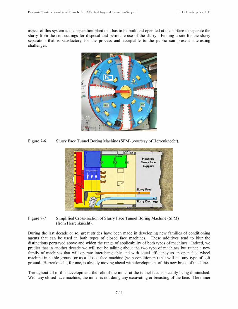
aspect of this system is the separation plant that has to be built and operated at the surface to separate the slurry from the soil cuttings for disposal and permit re-use of the slurry. Finding a site for the slurry separation that is satisfactory for the process and acceptable to the public can present interesting challenges.
Figure 7-6 Slurry Face Tunnel Boring Machine (SFM) (courtesy of Herrenknecht).
Figure 7-7 Simplified Cross-section of Slurry Face Tunnel Boring Machine (SFM) (from Herrenknecht).
During the last decade or so, great strides have been made in developing new families of conditioning agents that can be used in both types of closed face machines. These additives tend to blur the distinctions portrayed above and widen the range of applicability of both types of machines. Indeed, we predict that in another decade we will not be talking about the two type of machines but rather a new family of machines that will operate interchangeably and with equal efficiency as an open face wheel machine in stable ground or as a closed face machine (with conditioners) that will cut any type of soft ground. Herrenknecht, for one, is already moving ahead with development of this new breed of machine.
Throughout all of this development, the role of the miner at the tunnel face is steadily being diminished. With any closed face machine, the miner is not doing any excavating or breasting of the face. The miner
7-11
Design & Construction of Road Tunnels: Part 2 Methodology and Excavation Support Ezekiel Eneterprises, LLC
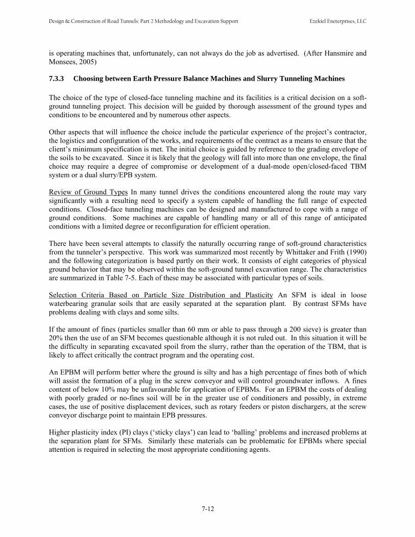
is operating machines that, unfortunately, can not always do the job as advertised. (After Hansmire and Monsees, 2005)
7.3.3 Choosing between Earth Pressure Balance Machines and Slurry Tunneling Machines The choice of the type of closed-face tunneling machine and its facilities is a critical decision on a soft-ground tunneling project. This decision will be guided by thorough assessment of the ground types and conditions to be encountered and by numerous other aspects. Other aspects that will influence the choice include the particular experience of the project’s contractor, the logistics and configuration of the works, and requirements of the contract as a means to ensure that the client’s minimum specification is met. The initial choice is guided by reference to the grading envelope of the soils to be excavated. Since it is likely that the geology will fall into more than one envelope, the final choice may require a degree of compromise or development of a dual-mode open/closed-faced TBM system or a dual slurry/EPB system. Review of Ground Types In many tunnel drives the conditions encountered along the route may vary significantly with a resulting need to specify a system capable of handling the full range of expected conditions. Closed-face tunneling machines can be designed and manufactured to cope with a range of ground conditions. Some machines are capable of handling many or all of this range of anticipated conditions with a limited degree or reconfiguration for efficient operation. There have been several attempts to classify the naturally occurring range of soft-ground characteristics from the tunneler’s perspective. This work was summarized most recently by Whittaker and Frith (1990) and the following categorization is based partly on their work. It consists of eight categories of physical ground behavior that may be observed within the soft-ground tunnel excavation range. The characteristics are summarized in Table 7-5. Each of these may be associated with particular types of soils. Selection Criteria Based on Particle Size Distribution and Plasticity An SFM is ideal in loose waterbearing granular soils that are easily separated at the separation plant. By contrast SFMs have problems dealing with clays and some silts. If the amount of fines (particles smaller than 60 mm or able to pass through a 200 sieve) is greater than 20% then the use of an SFM becomes questionable although it is not ruled out. In this situation it will be the difficulty in separating excavated spoil from the slurry, rather than the operation of the TBM, that is likely to affect critically the contract program and the operating cost. An EPBM will perform better where the ground is silty and has a high percentage of fines both of which will assist the formation of a plug in the screw conveyor and will control groundwater inflows. A fines content of below 10% may be unfavourable for application of EPBMs. For an EPBM the costs of dealing with poorly graded or no-fines soil will be in the greater use of conditioners and possibly, in extreme cases, the use of positive displacement devices, such as rotary feeders or piston dischargers, at the screw conveyor discharge point to maintain EPB pressures. Higher plasticity index (PI) clays (‘sticky clays’) can lead to ‘balling’ problem s and increased problems at the separation plant for SFMs. Similarly these materials can be problematic for EPBMs where special attention is required in selecting the most appropriate conditioning agents.
7-12
Design & Construction of Road Tunnels: Part 2 Methodology and Excavation Support Ezekiel Eneterprises, LLC
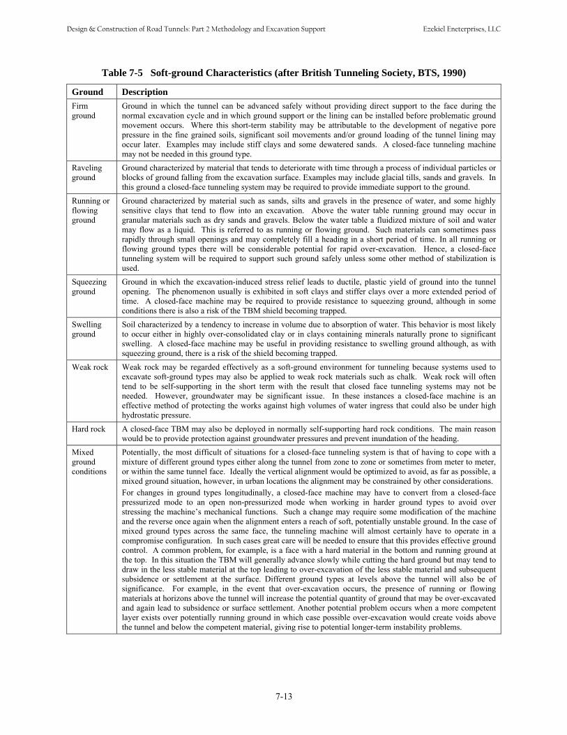
7-13
Table 7-5 Soft-ground Characteristics (after British Tunneling Society, BTS, 1990)
Ground Description Firm Ground in which the tunnel can be advanced safely without providing direct support to the face during the ground normal excavation cycle and in which ground support or the lining can be installed before problematic ground
movement occurs. Where this short-term stability may be attributable to the development of negative pore pressure in the fine grained soils, significant soil movements and/or ground loading of the tunnel lining may occur later. Examples may include stiff clays and some dewatered sands. A closed-face tunneling machine may not be needed in this ground type.
Raveling ground
Ground characterized by material that tends to deteriorate with time through a process of individual particles or blocks of ground falling from the excavation surface. Examples may include glacial tills, sands and gravels. In this ground a closed-face tunneling system may be required to provide immediate support to the ground.
Running or Ground characterized by material such as sands, silts and gravels in the presence of water, and some highly flowing sensitive clays that tend to flow into an excavation. Above the water table running ground may occur in ground granular materials such as dry sands and gravels. Below the water table a fluidized mixture of soil and water
may flow as a liquid. This is referred to as running or flowing ground. Such materials can sometimes pass rapidly through small openings and may completely fill a heading in a short period of time. In all running or flowing ground types there will be considerable potential for rapid over-excavation. Hence, a closed-face tunneling system will be required to support such ground safely unless some other method of stabilization is used.
Squeezing Ground in which the excavation-induced stress relief leads to ductile, plastic yield of ground into the tunnel ground opening. The phenomenon usually is exhibited in soft clays and stiffer clays over a more extended period of
time. A closed-face machine may be required to provide resistance to squeezing ground, although in some conditions there is also a risk of the TBM shield becoming trapped.
Swelling Soil characterized by a tendency to increase in volume due to absorption of water. This behavior is most likely ground to occur either in highly over-consolidated clay or in clays containing minerals naturally prone to significant
swelling. A closed-face machine may be useful in providing resistance to swelling ground although, as with squeezing ground, there is a risk of the shield becoming trapped.
Weak rock Weak rock may be regarded effectively as a soft-ground environment for tunneling because systems used to excavate soft-ground types may also be applied to weak rock materials such as chalk. Weak rock will often tend to be self-supporting in the short term with the result that closed face tunneling systems may not be needed. However, groundwater may be significant issue. In these instances a closed-face machine is an effective method of protecting the works against high volumes of water ingress that could also be under high hydrostatic pressure.
Hard rock A closed-face TBM may also be deployed in normally self-supporting hard rock conditions. The main reason would be to provide protection against groundwater pressures and prevent inundation of the heading.
Mixed Potentially, the most difficult of situations for a closed-face tunneling system is that of having to cope with a ground mixture of different ground types either along the tunnel from zone to zone or sometimes from meter to meter, conditions or within the same tunnel face. Ideally the vertical alignment would be optimized to avoid, as far as possible, a
mixed ground situation, however, in urban locations the alignment may be constrained by other considerations. For changes in ground types longitudinally, a closed-face machine may have to convert from a closed-face pressurized mode to an open non-pressurized mode when working in harder ground types to avoid over stressing the machine’s mechanical functions. Such a change may require some modification of the machine and the reverse once again when the alignment enters a reach of soft, potentially unstable ground. In the case of mixed ground types across the same face, the tunneling machine will almost certainly have to operate in a compromise configuration. In such cases great care will be needed to ensure that this provides effective ground control. A common problem, for example, is a face with a hard material in the bottom and running ground at the top. In this situation the TBM will generally advance slowly while cutting the hard ground but may tend to draw in the less stable material at the top leading to over-excavation of the less stable material and subsequent subsidence or settlement at the surface. Different ground types at levels above the tunnel will also be of significance. For example, in the event that over-excavation occurs, the presence of running or flowing materials at horizons above the tunnel will increase the potential quantity of ground that may be over-excavated and again lead to subsidence or surface settlement. Another potential problem occurs when a more competent layer exists over potentially running ground in which case possible over-excavation would create voids above the tunnel and below the competent material, giving rise to potential longer-term instability problems.
Design & Construction of Road Tunnels: Part 2 Methodology and Excavation Support Ezekiel Eneterprises, LLC

Permeability As a general guide the point of selection between the two types of machines is a ground permeability of 1x10⁻⁵ m/s, by using SFMs applicable to ground of higher permeability and EPBMs for ground of lower permeability. However, an EPBM can be used at a permeability of greater than 1x10⁻⁵ m/s by using an increased percentage of conditioning agent in the plenum. The choice will take into account the content of fines and the ground permeability. Hydrostatic Head High hydrostatic heads of groundwater pressure along the tunnel alignment add a significant concern to the choice of TBM. In situations where a high hydrostatic head is combined with high permeability or fissures it maybe be difficult to form an adequate plug in the screw conveyor of an EPBM. Under such conditions an SFM may be the more appropriate choice especially as the bentonite slurry will aid in sealing the face during interventions under compressed air. Settlement Criteria Both types of machine are effective in controlling ground movement and surface settlement – providing they are operated correctly. While settlement control may not be overriding factor in the choice of TBM type, the costs associated with minimizing settlement should be considered. For example, large quantities of conditioning agent may be needed to reduce the risk of over-excavation and control settlement if using EPBM in loose granular soils. See Section 7.5. Final Considerations Other aspects to consider when making the choice between the use of an SFM or an EPBM include the presence of gas, the presence of boulders, the torque and thrust required for each type of TBM and, lastly, the national experience with each method. These factors should be considered but would not necessarily dictate the choice. The overriding decision must be made on which type of machine is best able to provide stability of the ground during excavation with all the correct operational controls in place and being used. If both types of machine can provide optimum face stability, as is often the case, other factors, such as the diameter, length and alignment of the tunnel, the increased cutter wear associated with EPBM operation, the work site area and location, and spoil disposal regulations are taken into consideration. The correct choice of machine operated without the correct management and operating controls is as bad as choosing the wrong type of machine for the project. (After British Tunneling Society, BTS, 2005)
7.3.4 Sequential Excavation Method (SEM) In addition to shield tunneling methods discussed above, soft ground tunnels can be excavated sequentially by small drifts and openings following the principles of the Sequential Excavation Method (SEM), aka New Austrian Tunneling Method (NATM) first promulgated by Professor Rabcewicz (1965). The SEM has now been defined as “a method where the surrounding rock or soil formations of a tunnel or underground opening are integrated into an overall ring-like support structure and the following principles must be observed: • The geotechnical behavior must be taken into account • Adverse states of stresses and deformations must be avoided by applying the appropriate means of
support in due time.• The completion of the invert gives the above mentioned ring-like structure the static properties of a
tube.• The support means can/should be optimized according to the admissible deformations.
7-14
Design & Construction of Road Tunnels: Part 2 Methodology and Excavation Support Ezekiel Eneterprises, LLC

• General control, geotechnical measurements and constant checks on the optimization of the pre-established support means must be performed. (From ILF, 2004)
The underlying principle of SEM is actually the same as that stated by Sir Marc Brunel almost two centuries ago: “The great desideratum therefore consists in finding efficacious means of opening the ground in such a manner that no more earth shall be displaced than is to be filled by the shell or body of the tunnel and that the work shall be effected with certainty”. (Copperthwaite, 1906) In other words, never open more than is needed, can be excavated rapidly, and quickly supported. As applied to soft ground tunneling, SEM generally cannot compete with tunneling machines for long running tunnels but often is a viable method for: • Short tunnels• Large openings such as stations• Unusual shapes or complex structures such as intersections• Enlargements Refer to Chapter 9 for detail discussion regarding SEM/NATM.
7.4 GROUND LOADS AND GROUND-SUPPORT INTERACTION
7.4.1 Introduction The main objectives of tunnel support system are to (1) stabilize the tunnel heading, (2) minimize ground movements, and (3) permit the tunnel to operate over the design life. In general, the first two functions are provided by an initial support system, whereas the third function is preserved with a final lining. The loading on the support system and its required capacity is dependent on when and how it is installed and on the loadings that will occur after it is installed. If the final lining is installed after the tunnel has been stabilized by initial support, the final lining will undergo very little additional loadings such as contact grouting pressures, thermal stresses, groundwater pressure, and/or time dependent loading (creep). Generally, two types of loading have been considered to generate analytical solutions in tunneling in soil – overpressure loading and excavation loading. If a ground is assumed to be isolated and a pressure is applied to the upper surface, it is considered to be overpressure loading, where the support system is placed in the ground when it was unstressed and the lining and the ground is normally handled by applying lateral pressure to the ground. Practically the support system is never placed in an unstressed ground, instead it is placed in the opening after the initial deformation has occurred, and before any additional deformation occurs and the additional deformation induces loading into the support system. This induced loading is called excavation loading. The load developed on the support system (initial support and final lining) is a function of relative stiffness of the lining with respect to the soil (ground-lining interaction). Both analytical solutions and numerical methods have been commonly used by design engineers to evaluate the effect of the relative lining stiffness on the displacement, thrust, moments in the lining for various loading configurations. The available methods are summarized in this section. The reader should refer Chapter 10 for the final lining design practice.
7-15
Design & Construction of Road Tunnels: Part 2 Methodology and Excavation Support Ezekiel Eneterprises, LLC

7.4.2 Loads for Initial Tunnel Supports
This section presents a simplified system of determining the load on the initial support for circular and horseshoe tunnels in soft ground. These presented loads are patterned after Terzaghi’s original recommendations (1950) but have been simplified. In all cases, it is important that the experience and judgment of the engineer also be applied to the load selection. Table 7-6 shows the loads recommended for design of initial tunnel supports in soft ground.
Table 7-6 Initial Support Loads for Tunnels in Soft Ground
Geology Circular Tunnel Horseshoe Tunnel Notes
Running ground Lessor of full overburden or 1.0 B
Lessor of full overburden or 2.0 B
Floor indicated in horseshoe if compressed air used. Otherwise ignore compressed air
Flowing ground in air free
Lessor of full overburden or 2.0 B
Lessor of full overburden or 4.0 B
Stiff floor required in horseshoe
Raveling ground • Above water
table • Below water
table
Same as running ground Same as flowing ground
Same as running ground Same as flowing ground
Stiff floor required in horseshoe Stiff floor required in horseshoe
Squeezing ground Depth to tunnel springline
Depth to tunnel springline
Swelling ground Same as raveling ground
Same as raveling ground
The vast majority of tunnels in soft ground are driven with modern tunneling machines and are, therefore, circular. However, some tunnels are still driven by hand and are often horseshoe or modified horseshoe in shape, for example, pump stations or cross passages between transit tunnels. Therefore the table also provides initial support recommendations for horseshoe tunnels. The term tunnel liner actually should be broken into two concepts that have historically had distinct but related functions. Initial support is that support needed to make the soft ground tunnel opening stable and safe during the complete construction operation. It includes the gamut of support measures from reinforcement to grouting to freezing to shotcrete to ribs and boards to precast concrete segments and everything in between. Final lining is the concrete or other lining placed to make the tunnel acceptable aesthetically and functionally, e.g., smooth to air or water flow, and to make the tunnel permanently stable and safe for its design life of 100 years or more. While technically this distinction should still be made, with the advent of tunnel boring machines and high quality precast concrete lining systems (which are needed to propel the machines) this distinction is becoming blurred. For most modern tunnels a single lining of precast concrete segments is typically installed as the tunnel is advanced and used for both functions.
7-16
Design & Construction of Road Tunnels: Part 2 Methodology and Excavation Support Ezekiel Eneterprises, LLC

7.4.3 Analytical Solutions for Ground-Support Interaction The state of stress due to tunnel excavation and interaction between rock support system and supporting ground were previously discussed in Chapter 6. The elastic formulations and interaction diagram discussed in Section 6.6.2 are also valid for a tunnel in soft ground. Analytical solutions for ground-support interaction for a tunnel in soil are available in the literature. The solutions are based on two dimensional, plane strain, linear elasticity assumptions in which the lining is assumed to be placed deep and in contact with the ground (no gap), i.e., the solutions do not allow for a gap to occur between the support system and ground. Early analytical solutions by Burns and Richard (1964), Dar and Bates (1974), and Hoeg (1968) were derived for the overpressure loading, while solutions by Morgan (1961), Muir Wood (1975), Curtis (1976), Rankin, Ghaboussi and Hendron (1978), and Einstein et. al. (1980) were for excavation loading. Solutions are available for the full slip and no slip conditions at the ground-lining interface. Appendix E present the available published analytical solutions in Table E-2, as well as the background (excerpt from FHWA Tunnel Design Guidelines published in 2004). Appendix E also presents a sample analysis is in Table E-3, for a 22ft diameter circular tunnel with 1.5 ft thick concrete lining. The tunnel is located at 105 ft deep from the ground surface to springline and groundwater table is located 10 ft below the ground surface. Details of input parameters are shown in Table E-3a. The calculated lining loads from various analytical solutions are presented in Table E-3b. The result of finite element analysis is shown in Figure 7-8.
7.4.4 Numerical Methods Application of the analytical solutions is restricted when the variation of stress magnitude is significant with depth from the tunnel crown to the invert, such that assumptions made in the analytical solutions are not valid. Then, numerical method can be used to simulate support-ground interactions. Numerical modeling has been driven by a perceived need from the tunneling industry in recent times. It has led to large, clumsy and complex numerical models. Properly performed numerical modeling will lead engineers to think about why they are building it - why build one model rather than another - and how the design can be improved and performed effectively. An outline of the steps recommended for performing a numerical analysis for tunneling is as follow: Step 1: Define the objective of the numerical analysis Step 2: Select 2D or 3D approach and appropriate numerical software Step 3: Create a conceptual drawing of the analysis layout Step 4: Create geometry and finite element meshes Step 5: Select and apply boundary condition, initial condition and external loading Step 6: Select and apply constitutive model and material properties Step 7: Perform the simulation for the proposed construction sequence Step 8: Check / verify the results Step 9: Interpret the results For the analysis of tunneling in soil, continuum analysis is generally accepted, where the domain can reasonably be assumed to be a homogeneous media. The continuum analysis includes Finite Element Method (FEM), Finite Difference Method (FDM), and Boundary Element Method (BEM). The details of numerical analysis softwares are discussed in Section 6.6.3. Sample loads on the concrete lining
7-17
Design & Construction of Road Tunnels: Part 2 Methodology and Excavation Support Ezekiel Eneterprises, LLC
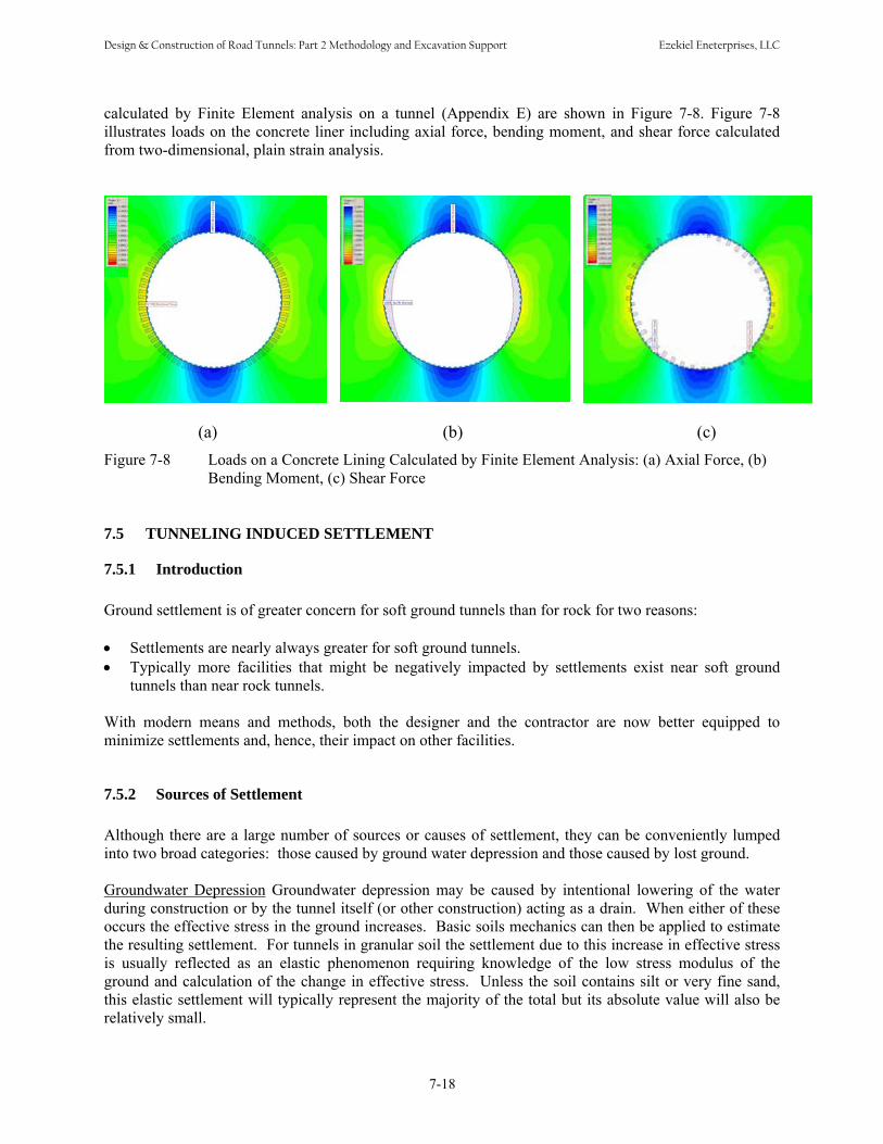
calculated by Finite Element analysis on a tunnel (Appendix E) are shown in Figure 7-8. Figure 7-8 illustrates loads on the concrete liner including axial force, bending moment, and shear force calculated from two-dimensional, plain strain analysis.
(a) (b) (c) Figure 7-8 Loads on a Concrete Lining Calculated by Finite Element Analysis: (a) Axial Force, (b)
Bending Moment, (c) Shear Force
7.5 TUNNELING INDUCED SETTLEMENT
7.5.1 Introduction Ground settlement is of greater concern for soft ground tunnels than for rock for two reasons: • Settlements are nearly always greater for soft ground tunnels.• Typically more facilities that might be negatively impacted by settlements exist near soft ground
tunnels than near rock tunnels. With modern means and methods, both the designer and the contractor are now better equipped to minimize settlements and, hence, their impact on other facilities.
7.5.2 Sources of Settlement Although there are a large number of sources or causes of settlement, they can be conveniently lumped into two broad categories: those caused by ground water depression and those caused by lost ground. Groundwater Depression Groundwater depression may be caused by intentional lowering of the water during construction or by the tunnel itself (or other construction) acting as a drain. When either of these occurs the effective stress in the ground increases. Basic soils mechanics can then be applied to estimate the resulting settlement. For tunnels in granular soil the settlement due to this increase in effective stress is usually reflected as an elastic phenomenon requiring knowledge of the low stress modulus of the ground and calculation of the change in effective stress. Unless the soil contains silt or very fine sand, this elastic settlement will typically represent the majority of the total but its absolute value will also be relatively small.
7-18
Design & Construction of Road Tunnels: Part 2 Methodology and Excavation Support Ezekiel Eneterprises, LLC

For fine grained soils, the situation is a bit more challenging but certainly manageable using normal soil mechanics approaches. With fine-grained soils, the conditions are reversed. In most instances, the settlement is mostly due to consolidation brought on by the changes in effective stress and hence is analyzed by the usual soil mechanics consolidation theories. In some instances, primarily if lenses of sands are contained in the soil, there may also be a relatively small contribution by elastic compression. In comparison to the settlement of granular soils, consolidation can lead to several inches of settlement when the consolidating soils are thick and the change in effective stress is significant. Lost Ground Lost ground has a number of root causes (at least nine) and is usually responsible for the settlements that make the headlines. By definition, lost ground refers to the act of taking (or losing) more ground into the tunneling operation than is represented by the volume of the tunnel. Thus it is highly reflective of construction means and methods. As will be discussed, modern machines can be a great help in controlling lost ground but in the end it usually comes down to quality of workmanship. For the purposes of this manual, the causes of lost ground are lumped into three groups: face losses, shield losses and tail losses.
• Face losses results from movement in front of and into the shield. This includes running, flowing,caving, and/or squeezing behavior of the ground itself or simply mining more ground than displaced by the tunneling machine.
• Shield losses occur between the cutting edge and the tail of the shield. All shields employ some degree of overcut so that they can be maneuvered. In addition, any time a shield is off alignment, the shield yaws, pitches, or plows when brought back to alignment. Mother Nature abhors a vacuum and the surrounding soils begin to fill these planned or produced voids the instant they are produced. Note that a one inch overcut plus one-eighth inch hard facing on a 20 foot shield produces lost groundof nearly two percent if not properly filled [1.125/12 (20) 3.1416 ]/ (10)2 3.1416 = 1.88%).
• Tail losses are similar to shield losses in that they are caused by the space being vacated by the tail itself as well as the extra space that must be provided between the tail and the support elements so those elements can be erected and so that they don’t become “iron bound” and seize the tail shield. However, like the shield losses, these tail voids will rapidly fill with soil if they are not first eliminated by grouting and/or expansion of the tunnel support elements.
7.5.3 Settlement Calculations Estimates of settlement in soft ground tunneling are just that, estimates. The vagaries of nature and of construction are such that settlements cannot be estimated in soft ground tunnels to the same level of confidence as, say, the settlement of a loaded beam. In tunneling we rely heavily on our experience with some assistance from analysis. Thus, there are two related methods to attack the problem: experience and empirical data. Experience can be used where a history of tunneling and of taking measurements exists. An example of this is Washington, D.C., where soft ground tunnels have been constructed in well-defined geology for over 40 years. During that time the industry has progressed from basic Brunel shields to the most current closed-face tunneling machines. For this case it would be anticipated that an experienced contractor would achieve between 0.5 and 1.0 percent ground loss (see Table 7-7). An inexperienced contractor would attain 1.0 to 2.0 percent loss.
7-19
Design & Construction of Road Tunnels: Part 2 Methodology and Excavation Support Ezekiel Eneterprises, LLC

Table 7-7 Relationship between Volumes Loss and Construction Practice and Ground Conditions
Case VL (%) Good practice in firm ground; tight control of face pressure within closed face machine in slowly raveling or squeezing ground 0.5
Usual practice with closed face machine in slowly raveling or squeezing ground 1.0
Poor practice with closed face in raveling ground 2
Poor practice with closed face machine in poor (fast raveling) ground 3
Poor practice with little face control in running ground 4.0 or more
When there is no record to rely upon, the design would have to be based strictly on empirical data and an engineering assessment of what the contractor could be expected to achieve with no track record to rely upon. In that case the above evaluations might be bumped up one-half percentage point each as an insurance measure
State-of-the-art pressurized-face tunnel boring machines (TBM) such as EPB and SFM as discussed in Section 7.3.2 minimize the magnitude of ground losses. These machines control face stability by applying active pressure to the tunnel face, minimizing the amount of overcut, and utilizing automatic tail void grouting to reduce shield losses. Typically, ground loss during soft ground tunnel excavation using this technology limits ground loss to 1.0 percent or less assuming excellent tunneling practice (adequate pressure applied to the face and effective and timely tail void grouting).
The volume of ground loss experienced during tunneling can be related to the volume of settlement expected at the ground surface (Peck, 1969). For a single tunnel in soft ground conditions, it is typically assumed the volume of surface settlement is equal to the volume of lost ground. However, the relationship between volume of lost ground and volume of surface settlement is complex. Volume change due to bulking or compression is typically not estimated or included in the calculations. Ground loss will produce a settlement trough at the ground surface where it can potentially impact the settlement behavior of any overlying or adjacent bridge foundations, building structures, or buried utilities transverse or parallel to the alignment of the proposed tunnel excavation. Empirical data suggests the shape of the settlement trough typically approximates the shape of an inverse Gaussian curve (Figure 7-9).
The shape and magnitude of the settlement trough is a function of excavation techniques, tunnel depth, tunnel diameter, and soil conditions. In the case of parallel adjacent tunnels, surface settlement is generally assumed to be additive. The shape of the curve can be expressed by the following mathematical relationships (Schmidt, 1974).
⎟⎟⎠
⎞⎜⎜⎝
⎛ −= 2
2
max 2exp
ixww 7-2
where:
w = Settlement, x is distance from tunnel or pipeline centerline i = Distance to point of inflection on the settlement trough
7-20
Design & Construction of Road Tunnels: Part 2 Methodology and Excavation Support Ezekiel Eneterprises, LLC
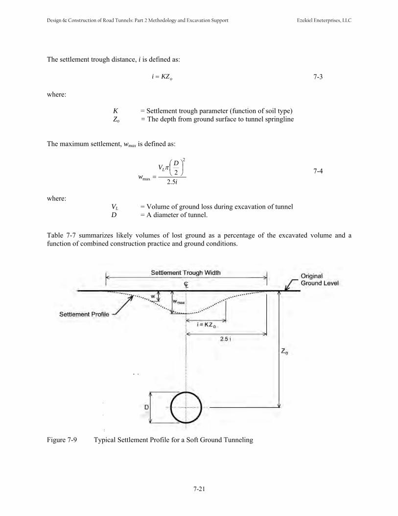
The settlement trough distance, i is defined as:
i = KZo 7-3 where:
K = Settlement trough parameter (function of soil type) Zo = The depth from ground surface to tunnel springline
The maximum settlement, wmax is defined as:
⎛ D ⎞2
VLπ ⎜ ⎟ 7-4⎝ 2 ⎠wmax = 2.5i
where: VL = Volume of ground loss during excavation of tunnel D = A diameter of tunnel.
Table 7-7 summarizes likely volumes of lost ground as a percentage of the excavated volume and a function of combined construction practice and ground conditions.
Figure 7-9 Typical Settlement Profile for a Soft Ground Tunneling
7-21
Design & Construction of Road Tunnels: Part 2 Methodology and Excavation Support Ezekiel Eneterprises, LLC

For geometrics other than a single tunnel, adjustments of the types given below should be made to obtain settlement estimates:
• For parallel tunnels three or more diameters apart (center to center), surface settlements are usuallyreasonably well predicted by adding the individual bell curves of the two tunnels. In good ground and with good practice, this will often give workable approximations up to the point where the tunnels aretwo diameters apart. On the other extreme, when the tunnels are less than one and one-half diametersapart, the volume of lost ground assumed for the second tunnel should be increased approximately one level in severity in Table 7-7 before the bell curves are added. Intermediate conditions may be estimated by interpolation.
• For over-and-under tunnels, it is usually recommended that the lower tunnel be driven first so that itdoes not undermine the upper tunnel. However, driving the lower tunnel will disturb the groundconditions for the upper. This effect may be approximated by increasing the lost ground severity of the second (upper) tunnel by approximately one level in Table 7-7 before adding the resulting two settlement estimates to approximate the total at the surface. (Monsees, 1996)
As shown in Figure 7-9 the width of the settlement trough is measured by an i value, which istheoretically the horizontal distance from the location of maximum settlement to the point of inflection of the settlement curve. The maximum value of the surface settlement is theoretically equal to the volume of surface settlement divided by 2.5 i. Figure 7-10 illustrates assumptions for i values (over tunnel radius R)for calculating settlement trough width in various ground conditions.
Figure 7-10 Assumptions for width of settlement trough (adapted from Peck, 1969)
7-22
Design & Construction of Road Tunnels: Part 2 Methodology and Excavation Support Ezekiel Eneterprises, LLC

The ground settlement also can be predicted by numerical methods. The numerical method is extremely useful when the tunnel geometry is not a circular or horse-shoe shape since analytical/empirical method is not directly applicable. A sample finite element settlement analysis is shown in Figure 7-11.
Figure 7-11 Example of Finite Element Settlement Analysis for Twin Circular Tunnels under Pile Foundations
7.6 IMPACT ON AND PROTECTION OF SURFACE FACILITIES
7.6.1 Evaluation of Structure Tolerance to Settlement Evaluation of structural tolerance to settlement requires definition of the possible damage that a structure might experience. Boscardin and Cording (1989) introduced three damage definitions for surface structures due to tunneling induced settlement (where settlement is calculated per Section 7.5):
1. Architectural Damage: Damage affecting the appearance but not the function of structures, usually related to cracks or separations in panel walls, floors, and finishes. Cracks in plaster walls greater than 1/64-in. wide and cracks in masonry or rough concrete walls greater than 1/32-in. wide arerepresentative of a threshold where damage is noticed and reported by building occupants.
2. Functional Damage: Damage affecting the use of the structure, or safety to its occupants, usually related to jammed doors and windows, cracking and falling plaster, tilting of walls and floors, andother damage that would require nonstructural repair to return the building to its full service capacity.
7-23
Design & Construction of Road Tunnels: Part 2 Methodology and Excavation Support Ezekiel Eneterprises, LLC
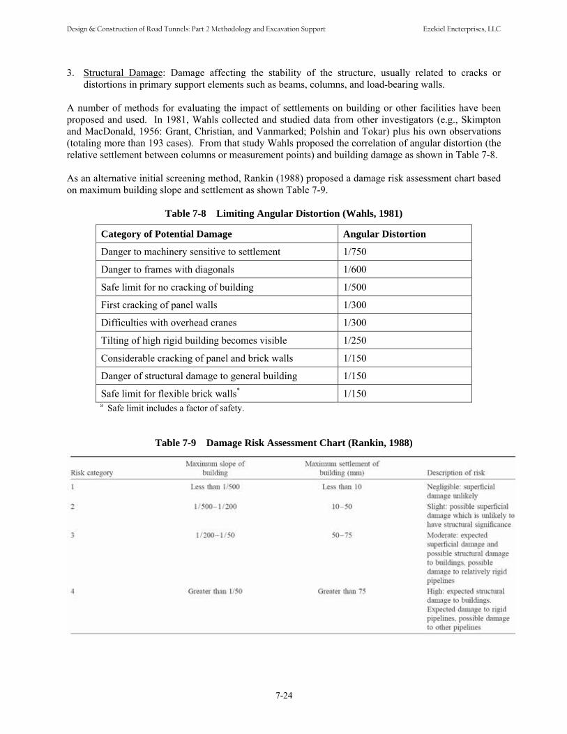
3. Structural Damage: Damage affecting the stability of the structure, usually related to cracks ordistortions in primary support elements such as beams, columns, and load-bearing walls.
A number of methods for evaluating the impact of settlements on building or other facilities have been proposed and used. In 1981, Wahls collected and studied data from other investigators (e.g., Skimpton and MacDonald, 1956: Grant, Christian, and Vanmarked; Polshin and Tokar) plus his own observations (totaling more than 193 cases). From that study Wahls proposed the correlation of angular distortion (the relative settlement between columns or measurement points) and building damage as shown in Table 7-8. As an alternative initial screening method, Rankin (1988) proposed a damage risk assessment chart based on maximum building slope and settlement as shown Table 7-9.
Table 7-8 Limiting Angular Distortion (Wahls, 1981)
Category of Potential Damage Angular Distortion
Danger to machinery sensitive to settlement 1/750
Danger to frames with diagonals 1/600
Safe limit for no cracking of building 1/500
First cracking of panel walls 1/300
Difficulties with overhead cranes 1/300
Tilting of high rigid building becomes visible 1/250
Considerable cracking of panel and brick walls 1/150
Danger of structural damage to general building 1/150
Safe limit for flexible brick walls* 1/150 a Safe limit includes a factor of safety.
Table 7-9 Damage Risk Assessment Chart (Rankin, 1988)
7-24
Design & Construction of Road Tunnels: Part 2 Methodology and Excavation Support Ezekiel Eneterprises, LLC
7.6.2 Mitigating Settlement Where the settlement is or would be caused by groundwater lowering the first, and usually the simplest, approach is simply to reduce or eliminate the conditions causing or allowing dewatering. This could include, for example: • Reduce drawdown at critical structures by reinjecting water, using impervious cutoff walls and the
like.• Using closed, pressurized face tunneling machines so that drawdown can not occur. Pressure at the
face should be equal to the groundwater head.• Grouting the ground around the tunnel to eliminate water inflow into the tunnel. Where the settlement is or could be caused by lost ground in the tunneling operation that settlement can nearly always be mitigated with proper construction means and methods. For example consider: • Requiring a closed face, pressurized TBM (EPB or SFM) and keep the pressure at least equal to if not
greater than the combined soil and groundwater pressure in the ground at tunnel level.• Immediately and completely grout the annular space between the tunnel lining and the ground at the
tail of the machine. Use automated grouting systems that will not permit the machine to advance without this void being simultaneously grouted.
• Control the operation (steering) of the machine so that it is not forced to pitch or yaw to make excessive alignment corrections. Each one percent of correction translates to a potential 1.5 percentof ground loss.
• Use compaction or compensation grouting to “make up” for ground loss before it migrates to thebuilding.
• Treat areas of loose soils by consolidation or jet grouting before tunneling into them.
7.6.3 Structure Protection The concept of and methods for structure protection are already woven into earlier paragraphs. First and foremost are the tunneling procedures of maintaining face pressure (control) and immediately grouting to fill the annular (or any other) void. The next step is ground improvement either by consolidation or jet grouting and, closely related compensation or compaction grouting. As a last resort, to be applied when all else appears to be unsuccessful and or unworkable, is underpinning. Like the use of compressed air, this method is now seldom used because modern tunneling techniques make it unnecessary. At times, as with the Pershing Square garage in Los Angeles it is still applicable, but most of the time practitioners believe it to have the possibility to do more damage than to be beneficial. Typical steps of underpinning method are summarized as follow: • Break out and hand excavate down to (or nearly to) the potentially impacted foundation.• Install piles or other founding elements to a bearing below and/or outside the impacted foundation
and the tunnel.• Install a needle beam or similar method to transfer the impacted foundation load to the new elements.• Preload the new elements, i.e., unload the impacted foundation onto those new elements
7-25
Design & Construction of Road Tunnels: Part 2 Methodology and Excavation Support Ezekiel Eneterprises, LLC

• Cut or release any load to the impacted foundation. At this point all load is transferred through the new elements to a bearing location/condition that is completely independent of the tunnelingoperation and the tunnel.
• As required or necessary remove or leave in place the original foundation.
Instrumentation and monitoring for the existing structures are discussed in Chapter 15 Geotechnical and Structural Instrumentation.
7.7 SOIL STABILIZATION AND IMPROVEMENT
7.7.1 Purpose Until fairly recently essentially all the design effort for tunnels in soft ground was to provide a support system or systems that would stabilize the existing ground during construction and then, perhaps with some modification, would permanently support the ground and provide an opening suitable for the long term mission of the tunnel. In the last two or three decades, however, the situation has changed such that in some applications a dual approach is taken. First, the characteristics of the ground are modified by stabilization and/or improvement to make that ground contribute more to its own stability. Then, secondly a supplementary but less costly support/lining system is installed to make the tunnel perform for its full lifetime. In this section the various methods of soil stabilization and improvement are summarized. References with more details on these methods are also given.
7.7.2 Typical Applications The decision to use soil stabilization or improvement must be made on each individual case. This decision may sometimes be easy with there being no other way to construct the tunnel. More often, the decision comes down to a trade off among treating the ground, using high-tech machines, and/or a combination of the two. With all of the possibilities it can be said that there are now no unacceptable construction sites. Table 7-10 summarizes the challenging ground sites and corresponding treatment methods.
Table 7-10 Ground Treatment Methods
Challenging Ground Conditions Treatment Method(s) Weak Soils • Vibro Compaction
• Dynamic Compaction• Compaction Grouting• Permeation Grouting• Jet Grouting
Ground Water • Dewatering• Freezing• Grouting
Unstable Face • Soil Nails• Spiling• Soil Doweling• Micro Piles
Soil Movement • Compensation Grouting• Compaction Grouting
7-26
Design & Construction of Road Tunnels: Part 2 Methodology and Excavation Support Ezekiel Eneterprises, LLC

It is to be noted that the boundaries between both ground conditions and treatment methods are not fixed. Also, the use of vibrocompaction techniques or dynamic compaction is typically applicable at or near the tunnel portals as these techniques are applied to the ground surface and are not effective beyond about 100 ft depth for vibro compaction and 35 ft depth for dynamic compaction. Both are generally effective only in granular soils. Readers are referred to the Ground Improvement Methods Reference Manual (FHWA, 2004) for more detailed discussion for the soil stabilization and improvement techniques presented below.
7.7.3 Reinforcement Methods Soil Nails Soil nails may be used to stabilize a tunnel face in soil during construction. Steel or fiberglass rods or nails are installed in the face and the resulting reinforced block(s) are analyzed for stability much as for usual slope stability analyses. Several methods (e.g., Davis, Modified Davis, German, French, Kinematrical, Golder, and Caltrans) are used for these analyses. Walkinshaw (1992) has studied these methods and concluded that all had some level of inconsistencies, such as: • Improper cancellation of interslice forces (Davis method)• Lateral earth pressures inconsistent with nail force and facing pressure distribution (all)• No redistribution of nail forces according to construction sequence and observed measurements (all
except Golder)• Complex treatment and impractical emphasis on nail stiffness (Kinematical) (after Walkinshaw,
1992: Xanthakos, 1994) For more discussion readers are referred to GEC No.7 Soil Nail Walls (FHWA, 2003), which also recommends that the Caltrans SNAIL program be used because it will handle both nails and tiebacks. However, it must be recognized that application of that or any other program must be tempered with appropriate judgment, measurements and case history experience. Soil Doweling Soil doweling entails the installation of larger reinforcement members than does nailing. These dowels act in tension like soil nails but are large enough in cross section that they also develop some shearing resistance where they pass through the sliding surfaces.
7.7.4 Micropiles As they are applied to tunneling, micropiles are essentially the same as soil dowels. These are typically drilled piles two to six inches in diameter that contain a large reinforcing bar centered in the hole and the hole backfilled with concrete. As opposed to pin piles that are typically installed at the surface (and that act in compression), the pin piles placed in tunnels typically act in tension and shear across the sliding surfaces. Soil nails, soil dowels, and pin piles are typically installed at the face of the tunnel to stabilize that face for construction. Thus, they are continually being installed and mined out of the face. For ease in this mining operation, fiberglass bars (rods) are typically used in these applications because they are much easier to mine out and cut. In contrast, spiling tends to look out around the perimeter of the tunnel, thus steel is more likely to be used for spiling bars or plates. Readers are also referred to “Micropile Design and Construction Reference Manual” (FHWA, 2005f) for more details.
7-27
Design & Construction of Road Tunnels: Part 2 Methodology and Excavation Support Ezekiel Eneterprises, LLC
7.7.5 Grouting Methods All grouting involves the drilling of holes into the ground, the insertion of grout pipes in the holes, and the injection of pressurized grout into the ground from those pipes. The details of the operations, however, are distinctly different. Readers are referred to the Ground Improvement Methods Reference Manual (FHWA, 2004) for more detailed discussion for the grouting techniques discussed hereafter. Permeation Grouting Permeation grouting involves the filling of pore spaces between soil grains (perhaps displacing water). The grout may be one of a number of chemicals (but is usually sodium silicate or polyurethane) or neat cement using regular, micro- or ultra- fine cement, along with chemicals and other additives. Once injected into the pore spaces, the grout sets and converts the soil into a stable, weak sandstone material. Permeation grouting usually involves grout holes at three to four feet centers with enough secondary holes at split spacing to verify that all the ground is grouted. If necessary to get full coverage all of the split spacing holes may have to be grouted and verification performed by the tertiary holes. Compaction Grouting Compaction grouting uses a stiffer grout than does permeation grouting. In compaction grouting the goal is to form a series of grout bulbs or zones four to six feet above and around the tunnel crown. By pumping the stiff grout in under pressure these bulbs compress (densify) the ground above the tunnel and between the tunnel and overlying facilities. The pipes for compaction grouting are pre-positioned and drilled into place and all the grouting pumps, hoses, header pipes, instrumentation and the like are in place before the tunnel drive begins. Instrumentation is read as the tunnel approaches and passes a facility and the grouting operation is adjusted real time in response to the movement readings. Actually, in most applications it is possible to either pre-heave the ground or to jack it back up (at least partially) by pumping more grout at higher pressures. Compensation Grouting Compensation grouting is, in some ways, similar to compaction grouting. The goal is to monitor ground movements, primarily between the tunnel and any overlying facility. When it is apparent that ground is being lost in the tunneling operation, a grout, typically slightly more liquid than the compaction grout mix, is injected to replace (compensate for) the lost ground. As indicated the differences between these two schemes are relatively minor – compaction grouting seeks to recompact the ground by forming grout bulbs, compensation grouting seeks to refill voids created by the tunneling operations. Jet Grouting Jet grouting is the newest of the grouting methods and is rapidly becoming the most widely used. Jet grouting uses high pressure jets to break up the soils and replace them with a mixture of excavated soils and cement, typically referred to as “soilcrete”. There are a number of variations of jet grouting depending on the details of the application and on the experience and expertise of both the designer and the contractor. The design of a jet-grouted column is influenced by a number of interdependent variables related to in situ soil conditions, materials used, and operating parameters. Table 7-11 presents a summary of the principal variables of the jet grouting system and their potential impact on the three basic design aspects of the jet-grouted wall: column diameter, strength and permeability. Table 7-11 gives typical ranges of operating parameters and results achieved by the three basic injection systems of jet grouting. It should be noted however, that the grout pressures indicated in this table are based on certain equipment and can vary. This table can be used in feasibility studies and preliminary design of jet-grouted wall systems.
7-28
Design & Construction of Road Tunnels: Part 2 Methodology and Excavation Support Ezekiel Eneterprises, LLC

The actual operating parameters used in production are usually determined from initial field trials performed at the beginning of construction.
Jet grouting is frequently used as a ground control measure in conjunction with tunneling in soft ground using Sequential Excavation Method (Chapter 9).
Table 7-11 Summary of Jet Grouting System Variables and their Impact on Basic Design Elements
Principal Variables General Effect of the Variable on Basic Design Elements (Strength, Permeability and Column Diameter)
(a) Jet-Grouted Soil Strength
Degree of mixing of soil and grout Strength is higher and less variable for higher degree of mixing
Soil type and gradation Sands and gravels tend to produce stronger material while clays and silts tend to produce weaker material.
Cement Factor Strength increases with an increase in cement factor (weight of cement per volume of jet-grouted mass).
Water/cement ratio of grouted mass Strength of the jet-grouted soil mass decreases with increase in in situ water/cement ratio.
Jet grouting system The strength of the double fluid system may be reduced due to air entrapment in the soil-grout mix.
Age of grouted mass As the jet-grouted soil mass cures, the strength increases but usually at a slower rate than that of concrete.
(b) Wall Permeability
Wall continuity
Overall permeability of a jet grout wall is almost entirely contingent on the continuity of the wall between adjacent columns or panels. Plumb, overlapping multiple rows of columns would produce lower overall permeability. In case of obstructions (boulders, utilities, etc.) if complete encapsulations is not achieved then overall permeability may be increased due to possible leakage along the obstruction-grout interfaces.
Grout composition
Assuming complete wall continuity and complete replacement of in situ soil, the lowest permeability which can be obtained is that of the grout (typically 10-6 to 10-7 cm/sec). Lower permeabilities may be possible if bentonite or similar waterproofing additive is used.
Soil composition
If complete replacement is obtained (as may be possible with a triple fluid system) then soil composition does not matter. Otherwise, if uniform mixing is achieved then finer grained soils would produce lower permeabilities as compared to granular soils.
(c) Column Diameter
Jet grouting system The diameter of the completed column increases in size as the number of fluids is increased from the single to the triple fluid systems.
Soil density and gradation As density increases, column diameter reduces. For granular soils, the diameter increases with reducing uniformity coefficient (D60/D10).
Degree of mixing of soil and grout Larger and more uniform diameters are possible with higher degree of mixing.
7-29
Design & Construction of Road Tunnels: Part 2 Methodology and Excavation Support Ezekiel Eneterprises, LLC
7.7.6 Ground Freezing As with much of tunneling technology, ground freezing was developed first in the mining industry and was probably first used in sinking mine shafts. For a mine the shaft (and the mine) is located where the ore is. Thus, means of obtaining access in unfavorable ground conditions, of providing emergency support in unstable ground below the water table, and of maintaining stability of working faces below the water table, such as freezing, often had their roots in the mining industry. In its simplest form, ground freezing involves the extraction of heat from the ground until the groundwater is frozen. Thus converting the groundwater into a cementing agent and the ground into a “frozen sandstone”. The heat is extracted by circulating a cooling liquid, usually brine, in an array of pipes. Each pipe is actually two nested pipes, with the liquid flowing down the center pipe and back out through the annulus between the pipes. When the pipes are close enough and the time long enough, the cylinders of frozen soil formed at each pipe eventually coalesce into one solid frozen mass. This mass may be a ring or donut as needed to support a shaft or a solid block of whatever shape necessary to stabilize the working face or heading. Because of the dearth of engineering data on the properties of frozen ground (especially clays) it is recommended that two steps be taken early in any design of ground freezing: 1. A qualified consultant be engaged to advise on the design and construction of the project. Advice
from such a professional is essential for the work and will pay for itself many times over.2. Laboratory tests be designed and carried out using soil samples from the actual site. Only in this
manner can meaningful properties of frozen soil be obtained for the site involved for purposes ofconceptual engineering (“scoping the problem”).
However, a few general guidelines can be stated as follows (after Xanthakos, 1994). 1. Pipes are normally spaced 3 to 4 feet apart.2. Select a spacing-to-diameter ratio <13 (for pipes 120 mm or less in diameter).3. Use a brine temperature <25˚ C.4. Provide 0.013 to 0.025 tons of refrigeration per foot of freeze pipe. 5. Determine typical frozen ground properties by laboratory testing. Groundwater flow across the site requires special considerations closer pipe spacing, multiple rows of pipes and the like. Groundwater flow velocities approximately >2 m/day may impede or prevent freezing. A number of special challenges associated with ground freezing should be considered in both the design and construction stage. Those are creep of frozen ground, sensitivity of frozen ground properties to loading condition, ground heave or settlement, and others. Readers are referred to the discussions and details of ground freezing application in Chapter 12.
7-30
Design & Construction of Road Tunnels: Part 2 Methodology and Excavation Support Ezekiel Eneterprises, LLC
CHAPTER 8 TUNNELING IN DIFFICULT GROUND
8.1 INTRODUCTION Engineers like to work with materials having defined characteristics that do not change from one location or application to another. Unfortunately, geology seldom if ever cooperates with this natural desire but instead tends to present new and challenging conditions throughout the length of a tunnel. Some of these conditions approach the “ideal” closely enough that they can be approached as presented for rock and soft ground in Chapters 6 and 7. However, in many cases special approaches or arrangements must be made to safely and efficiently drive and stabilize the tunnel as it passes through this “Difficult Ground”. The factors that make tunneling difficult are generally related to instability, which inhibits timely placement or maintenance of adequate support at or behind the working face; heavy loading from the ground which creates problems of design as well as installation and maintenance of a suitable support system; natural and man-made obstacles or constraints; and physical conditions which make the work place untenable unless they can be modified. This chapter is an update of the Chapter 8 “Tunneling in Difficult Ground” of the 2nd Edition Tunnel Engineering Handbook authored by Terrence G. McCusker (Brickel, et al., 1996) and emphasizes on creating and maintaining stable openings by mining or boring in difficult ground which actively resists such efforts. Chapters 6 through 10 presents design recommendations and requirements for mined and bored road tunnels. Mining sequentially based on the sequential excavation method (SEM) principles is discussed in Chapter 9. Chapter 10 addresses the design of various types of permanent lining applicable for rock tunnels.
8.1.1 Instability Instability can arise from: lack of stand-up time, as in non-cohesive sands and gravels (especially below the water table) and weak cohesive soils with high water content or in blocky and seamy rock; adverse orientation of joint and fracture planes; or the effects of water. The major problems with mixed face tunneling can also be ascribed to the potential for instability and this class of tunneling will be discussed under this heading.
8.1.2 Heavy Loading When a tunnel is driven at depth in relatively weak rock, a range of effects may be encountered, from squeezing through popping to explosive failure of the rock mass. Heavy loading may also result from the effects of tunneling in swelling clays or chemically active materials such as anhydrite. Adverse orientation of weak zones such as joints and shears can also result in heavy loading, but this is usually dealt with as a problem of instability rather than loading. Combinations of parallel and intersecting tunnels are a special case in which loadings have to be evaluated carefully.
8.1.3 Obstacles and Constraints Natural obstacles such as boulder beds in association with running silt and caverns in limestone are just two examples of natural obstacles that demand special consideration when tunneling is contemplated. In urban areas, abandoned foundations and piles present manmade obstructions to straightforward tunneling
8-1
Design & Construction of Road Tunnels: Part 2 Methodology and Excavation Support Ezekiel Eneterprises, LLC

while support systems for existing buildings and for future developments present constraints which may limit the tunnel builder's options. In urban settings, interference conflicts, public convenience or the constraints imposed by the need or desire for connection to existing facilities will sometimes result in the need to construct shallow tunnels, which have a range of problems from working in confined spaces, avoiding subsidence and uneven ground loading and support.
8.1.4 Physical Conditions In areas affected by relatively recent tectonic activity or by ongoing geothermal activity, both high temperatures and noxious, explosive or deadly gases may be encountered. Noxious gases are also commonly present in rock of organic origin; and elevated temperatures are commonly associated with tunneling at depth. In an urban setting, contaminated ground may be encountered and will be especially troublesome when found in association with other difficult conditions. Where appropriate, some information is provided as to the reasons why the condition under discussion creates problems for construction. Some examples of each of the conditions referred to above are discussed briefly to yield insight into the problems and to define the range of solutions available.
8.2 INSTABILITY
8.2.1 Non-Cohesive Sand and Gravel Cohesion in sands is more than a matter of grain size distribution. For instance, beach-derived sands normally contain salt (unless it has been leached out), which aids in making sand somewhat cohesive regardless of grain size. The moisture content then becomes a determining factor. The age and geologic history of the deposit is also important since compacted dune sands with “frosted” grain surfaces may develop a purely mechanical bond; and leaching and redeposit of minerals from overlying strata may also provide weak to strong chemical bonding. As discussed in Chapter 7, a very low water content amounting to less than complete saturation will provide temporary apparent cohesion as a fresh surface is exposed in tunnel excavation because of capillary forces or “negative pore pressure.” This disappears as the sand dries and raveling begins. Nevertheless, some unlooked-for stand up time may be available. In this case, it is important not to overrate the stability of the soil. As it dries out, the cohesion will disappear and it cannot be restored by rewetting the ground. If groundwater is actually flowing through the working face, any amount may be sufficient to permit the start of a run which can develop into total collapse as shown in Figure 8-1.
There is no such thing as a predictably safe rate of flow in clean sands. Uncontrolled water flows affect more than the face of the excavation. If the initial support system of the tunnel is pervious, water flowing behind the working face will carry fines into the tunnel and may create substantial cavities--sometimes large enough to imperil the integrity of the structural supports. This phenomenon occurred in Los Angeles where a ruptured water main caused sufficient flow through a tunnel support system to cause a failure and resulting large sink hole in the street.
8-2
Design & Construction of Road Tunnels: Part 2 Methodology and Excavation Support Ezekiel Eneterprises, LLC

While factors such as compaction or chemical bonding may permit some flow without immediate loss of stability, this is not a reliable predictor. Soil deposits are hardly ever of a truly uniform nature. It has been observed in soft ground tunnels in recent deposits that all that is necessary to trigger collapse may be the presence of sufficient water to result in a film on the working face; i.e., there is no negative pore pressure to assist in stabilizing the working face. Of course, there is never a safety factor arising from surface tension (capillary action) in coarse sand or gravel.
Key: A: Flowing Sand B: Sand at Normal Angle of Repose
Figure 8-1 Flowing Sand in Tunnel
The cleaner the sand, the more liable it is to run or flow when exposed in an unsupported vertical face during tunnel construction. Single sized fine grained sands (UCS classification SP) are the most troublesome, closely followed by SP-SM sands containing less than about 7% of silt and clay binder. Saturated sands in these classes have been observed to flow freely through sheet piles and to settle into fans having an angle of repose of less than 5°. Unconfined SP sands will run freely, as in an hourglass, whether wet or dry, having some stability only when damp but less than saturated (no piezometric head). The large proportion of the sand particles of the same size allow the sand to move almost as freely over one another as would glass marbles. Silt, intermediate in grain size between sand and clay, may behave as either a cohesive or non-cohesive material. In some areas it is common to find thin seams of saturated fine sandy silt trapped between clay beds in glacial deposits. In general, unless the seams are thicker than about 9-12 inches, when the silt layer is exposed in the wall of an excavation, the soil slumps out at intervals leaving a series of small shallow caves like entrances to burrows. The water appears to drain fast enough from the increased surface area exposed so that the remainder of the exposed material stabilizes. The usual problem encountered with running sand is settlement and cratering at the surface with damage to structures or utilities in the area. If the ground is permeable, consolidation grouting of the entire sensitive area can be undertaken to stabilize the soil before tunneling. If dewatering is successful in depressing the water table below the tunnel invert, it may be found that the sand is just as unstable dry as
8-3
Design & Construction of Road Tunnels: Part 2 Methodology and Excavation Support Ezekiel Eneterprises, LLC
wet. The alternative of using compressed air is attractive, provided the working pressure is very carefully controlled; but even so, the ground may be too dried out for stability. If the face is a full face of sand and similarly weak materials, a slurry machine or an earth pressure balance machine, will be required. In general, rotary head tunneling machines for soft ground tunnels require very similar physical properties over the entire working face and the entire job. If these conditions do not prevail, then weaker ground, and running sands in particular, must be prevented from entering the shield more rapidly than is proper for the rate of advance. Slurry shields have the best opportunity of controlling variable conditions where running sands are present; but they will prove difficult to keep on line and grade in mixed face conditions if one of the beds present is even a strong clay. If the sand and clay beds are more or less evenly distributed (e.g., a varved clay), then this problem may not arise. Of the digger type shields, neither extensible poling plates nor orange peel breasting have proved to be generally successful, hence these machines are now rarely used. A problem with all shield construction is the necessary difference in diameter between the shield and the lining. If the soil has no stand-up capability by the time it is exposed in the upper part of the tunnel before expansion of a primary lining or introduction of pea gravel or more commonly, grout into the annular space for non-expanded linings, then there will be loss of ground. If the unfilled annular space averages one inch in a 20 ft tunnel, the lost ground from this single cause is approximately 1.7% shown in Table 7.2 as “poor” practice. Even if only local ravelling takes place, it may choke off the flow of grout before the void can be filled with a continuous supporting fill material. This loss of ground results in a contribution to settlement.
8.2.2 Soft Clay For the purposes of this discussion, soft clay includes any plastic material that will close around a tunnel excavation if free to do so. This will be the case if the overburden pressure at spring line exceeds the shear strength of the clay by a factor of about three or more. However, if the clay is sensitive and loses strength when remolded, the remolded strength will govern some of the clay behavior during tunnel construction. The phenomenon of sensitivity is mediated by several factors that cannot be fully discussed here but, in general, sensitivity may be suspected in clays with a high moisture content. Particularly at risk are marine clays from which the salt has been leached. The loss of strength may lie within a wide range, the ratio of undisturbed to remolded strength sensitivity being from 2 to 1,000. Moderate sensitivity of 2 to 4 is quite common. During remolding, the void ratio in the clay is reduced and free water is released. When this free water has access to a drainage path such as a sand bed or the tunnel itself, there will be a volume change in the soil mass which will result in surface settlement. As discussed in Chapter 7, Equation 7-1 is used to calculate a Stability Number to estimate ground behavior in tunneling. Table 7-2 summarizes the behavior of cohesive soils during excavation. As shown in Table 7-2, if the cohesive soil is to be stabilized so that closure around the tunnel lining is minimized and stable control of line and grade are maintained, the critical number must be reduced below about 5; this will enable reasonable control of alignment and grade. Equation 7-1 can be writem to the following equation:
P a = P z − (N × S ) 8-1crit u
where Ncrit is the critical number, Pz is the overburden pressure at tunnel spring line, Pa is the working pressure in a compressed air tunnel or the equivalent average pressure provided by the initial support system, and Su is the undrained shear strength of the soil in compatible units. As an example, if N is to be maintained at a value of 5, the overburden pressure is 40 psi and the unconfined shear strength of the soil
8-4
Design & Construction of Road Tunnels: Part 2 Methodology and Excavation Support Ezekiel Eneterprises, LLC

is 1,000 psf = 7 psi, then from Equation 8-1, the required working pressure in the tunnel will be (40 - 5 × 7) = 5 psi. From this same equation, it can be seen that if the shear strength of the soil is reduced by remolding caused by passage of the shield through the ground to a value of 250 psf, then the required air pressure for stability increases to over 30 psi, transforming the project from a relatively straightforwardone to a difficult one. Attempting to calculate the required volume of grout injection into the annular void between shield excavation and lining in clays often is not a fruitful exercise. It will certainly be possible to inject the requisite volume of grout, but it may be difficult to make it flow around the tunnel perimeter in an even layer. The best results are obtained by establishing multiple simultaneous injection points permanently fixed within the shield tail and passing through the tail seals. Grout is injected throughout the time the shield is in motion. For this system to work, the lining must be a bolted segmented lining with built-in gashets between segments. It must be expected that for simultaneous injection through multiple ports while the shield is in motion there will be a substantial learning curve before all elements of the system are functioning smoothly to achieve the desired result. It is generally difficult to use any mechanical excavation equipment in this type of ground except for a slurry shield or earth pressure balance shield (EPB). These days, the two types of machine are approaching interchangeability with the continuing development of chemical additives (conditioners). The edge goes to slurry machines in coarse geology and/or where the rock crusher may be needed to reduce rock or boulders to a size that will pass the machine. The EPB is preferred as being somewhat more flexible in varying conditions and somewhat less expensive than a slurry shield. In order to control pressure in the plenum chamber behind the cutterhead, a screw conveyor is required. The rotational speed of the screw is matched to the advance rate of the EPB and pressure in the plenum is monitored using multiple sensors. If boulders are likely to be encountered, especially if they will be larger than can pass through the screw conveyor, the cutterhead must be fitted with disk cutters in addition to the drag bits normally associated with this type of machine. This topic is covered in more detail below in Section 8.4.1 dealing with boulders.
8.2.3 Blocky Rock As discussed in Chapter 6, rock is a basically strong material which requires little or no structural support when intact; although it may require protection from exposure to air, water or from fluids conveyed in the tunnel. However, when the rock joints and fractures are open sufficiently that the natural rugosity of the block surfaces will not prevent movement of rock blocks or substantial fragments, the rock is said to be “blocky.” If the joints and fractures contain clay-like material resulting from weathering or light shearing, then the rock is described as “blocky and seamy.” As can be seen from Table 6-7, this may raise the rock load by a factor of approximately three. In zones where the rock has small folds, but is open along the direction of the folds, it may be free to move in only one direction. Such rock is still blocky. When rock is subjected to the action of explosives, high-pressure gases flow into any fissures in the rock before they have finished their explosive and rock-fracturing expansion. Even in hard granite, a result of blasting is the creation of micro-fissures extending well outside the blasted perimeter. In blocky rock, the effect may well extend more than a tunnel diameter outside the desired finished surface; a good deal of overbreak and potential loosening and movement of blocks is likely to result. Another problem with this type of rock is that it is highly susceptible to the destabilizing effects of water flowing through the fracture system with sufficient energy to dislodge successively more rock. This action is dealt with more fully in a later section. Finally, it is quite likely when blocky and seamy rock is encountered in a tunnel excavation, especially in heavily folded strata, that there will be zones where the
8-5
Design & Construction of Road Tunnels: Part 2 Methodology and Excavation Support Ezekiel Eneterprises, LLC
weathering has proceeded to a conclusion resulting in the presence of weak earth-like material with little capacity to sustain loads or to preserve the tunnel outline. All of the rock conditions described require early and carefully placed primary support to preserve ground stability and to provide a safe workplace. Even before support installation, it is necessary to minimize surprises by scaling off any loose rock which will present a hazard to the crews installing the support system. Many still prefer to use steel ribs and wood lagging in this type of rock. It provides positive support and is quickly installed in tunnels less than about 5 meters in diameter. Unfortunately, crews still have to work under the unsupported rock to install the ribs and lagging; the material costs are high; the presence of timber results in the possibility of future uneven loading on the permanent tunnel lining as wood rots out and steel corrodes; and it becomes relatively difficult to ensure good contact between the lining concrete and the rock even after contact grouting. For these reasons the use of shotcrete and rock bolts has become popular. In rock known to be blocky and therefore to need support, an initial layer of shotcrete about 5 cm thick should be applied as soon as possible in the tunnel crown. This is followed by the installation of pattern rock bolts whose length and diameter are governed principally by the tunnel diameter. (See Chapter 6 for more details)
8.2.4 Adverse Combinations of Joints and Shears Jointing systems in rock arise from many causes, some of which are noted here. Sedimentary rocks, and particularly limestone, typically have three more or less orthogonal joint sets arising from the modes of deposition and induration which formed them. Not all joints are continuous, but those in any set are parallel. There may be many sets or, in weak, massive sandstone, for instance, only one or two. Joints and fracture systems combine to break up the rock mass into interlocking fragments of varying sizes and degrees of stability. In the absence of direct evidence to the contrary, it should be assumed that shears and faults are continuous throughout their intersection with the tunnel excavation. In schistose materials, weathering usually follows a foliation plane to great depths, even in temperate climates when a weak zone has been formed by slippage along that plane. Other faulting may cause the development of extensive fracture systems in any direction. A section through the project area perpendicular to the strike of the exposed surfaces in schistose materials will generally reveal a saw-tooth profile with one of the surfaces parallel to the foliation. Continuation of the plane thus defined to tunnel elevation will be a preliminary indicator of the presence of sheared and weathered rock in the excavation. Continuous joints and shears can define large blocks with little or nothing to hold them in place once the tunnel excavation has been completed. It is important to identify the locations of blocks with the potential for falling out in order to provide support during cautious excavation. For large diameter tunnels in particular, this requires an assessment of the potential before construction begins, mapping during construction, and control of drift size and round length to ensure against complete exposure of an unstable block in a single round. Readers are referred to Chapter 6 for details. The difficulty of controlling the correct placement of steel sets in multiple drift headings works against the use of this kind of support. Initial rock bolting followed by reinforced shotcrete is a reasonable approach. In all cases where rock bolts have to be located to take direct and reasonably predictable loads, it is better that they be installed ahead of the shotcrete while the joint locations are still visible. If mechanical rock bolt installers cannot be used, then the crews must be protected by overhead cages.
8-6
Design & Construction of Road Tunnels: Part 2 Methodology and Excavation Support Ezekiel Eneterprises, LLC
8.2.5 Faults and Alteration Zones Tectonic action, high pressure and high temperatures may metamorphose rock into different structures with unpredictable joint patterns. The uplift and folding of rocks by tectonic action will cause fracturing perpendicular to the fold axis along with faulting where the rock cannot accommodate the displacements involved, so that shears develop parallel to the fold axis. Other types of faults arise as the earth accommodates itself to shifting tectonic forces. Faults or shears may be thin with no more significance than a continuous joint or they may form shear zones over a kilometer wide in which the rock is completely pulverized but with inclusions of native rock, sometimes of large size. All of the conditions briefly described above may be additionally complicated by the presence of locked-in stress, high overburden loads, or water. Dealing with the conditions encountered in such fault zones and weathered intrusive zones depends on the excavation method in use, the depth below the ground surface, the strength of the fault gouge, the sheared material or the weathered or altered rock, and the water conditions. Water problems are discussed in general in the next section, including consideration of the difficult water conditions commonly found in association with faults; however, to the extent that they affect the selection of construction methods appropriate to fault crossings, they are referred to here. Current technology provides other solutions, such as the use of precast concrete lining in the weak ground with supplementary jacking capability to enable the lining to provide the jacking reaction for the thrust of the TBM. In general, fault crossings offer conditions akin to those of mixed face tunneling and the same methods are available to deal with them. Different circumstances come into play with deeper tunnels, especially if these are of large diameter. Such tunnels are usually long and logistics are important. The comparative lengths of fault zone and normal tunnel dictate that the construction method be efficient for the normal tunnel. Nevertheless, sufficient flexibility is required to permit safe and reasonably expeditious construction through the worst conditions likely to be encountered. Drill and blast excavation is still commonly used in such tunnels. Rock bolts and shotcrete then become the preferred support system, although steel ribs and lagging or steel ribs with shotcrete are also still used. TBM successes in these conditions have been few. There are two principal problems: the loose material in the fault runs into the buckets and around the cutters and stalls the cutterhead; and if the fault contains cohesive material, it squeezes and binds the cutterhead and shield with similar results. One solution to the problem of loose or loosened ravelling and running material is to establish a grout curtain ahead of the TBM and then to maintain it by continuing a grout and excavation cycle throughout the fault-affected portion of the drive. Even if imperfect--as consolidation grouting tends to be, especially when placed from within the tunnel in conditions providing limited access--it is likely that a properly designed and executed program will add sufficient stability to the ground to permit progress. It should be noted that any such program will be expensive and time-consuming. It is therefore unlikely that any contractor will willingly do the necessary work unless it has already been envisaged in the contract as a priced bid item. It is also important to recognize that if water is running into the tunnel through the working face, a bulkhead will be required to stop the flow while the initial grouting is in progress. Grouting into running water is a slow and expensive way to establish a grout seal. Within limits, the squeezing problem can be dealt with in part in TBM tunneling by tapering the shield and making its diameter adjustable within limits; and by bevelling the cutterhead itself to the extent that this is possible without interfering with the efficiency of the buckets. Expandable gauge cutters are also
8-7
Design & Construction of Road Tunnels: Part 2 Methodology and Excavation Support Ezekiel Eneterprises, LLC
used, but this is still a developing technology. One of the problems is that there is a tendency for local shearing of the cutter supports to result in an inability to withdraw the cutter once it has been extended. Also, since such cutters are acting well outside the radius of the buckets, muck which falls to the invert is not collected but provides an obstruction the cutters must pass through repeatedly. This grinds the debris finer and finer and abrades the cutter mounts as well as the cutter disk. This makes it necessary to provide means for eccentric cutterhead rotation so that the invert is properly swept. Unfortunately, squeezing is commonly, if not most often, manifested preferentially in the tunnel invert.
8.2.6 Water It was Terzaghi's view that the worst problems of tunneling could be traced to the presence of water. Among other things, he considered that (except for circular tunnels) it was prudent to double the design rock load on the tunnel lining when the tunnel was below the water table. This in itself would not be a serious problem, since most tunnel linings are already limited as to their minimum dimensions by problems of placement rather than by design considerations. However, there are many other problems that are associated with the presence of water. Several are discussed below, working in sequence from clay to rock and, within rock, from weak and fractured to strong and intact.
8.2.6.1 Clay Most clays are at least slightly sensitive. This arises from the microstructure of clay soils which are composed largely of platy minerals. As with a heap of coins, the packing is not perfect, even though the clay is relatively impermeable. Each fragment is held in place by some combination of free body equilibrium forces, ionic interaction and chemical or mechanical bonds at the contact points. The pores of the clay are generally filled with water, which may contain salts in solution. Disturbance of the clay results in disruption of the bonding, migration of water and at least temporary weakening of the clay structure. The free water will be released at any temporary boundaries formed by shearing. As the clay reconsolidates, it is likely to gain strength over the initial condition, but this will be a protracted process. The immediate effect, and the one that affects tunnel construction, is loss of shear strength throughout the disturbed mass. In organic silty clays, the sensitivity is commonly about 4, indicating a fourfold loss of strength upon remolding. This is associated with an initial water content of about 60%. As shown on Page 8-4, a four fold loss of strength can result in more than a sixfold increase in the required support. In any one material, the sensitivity may vary greatly, depending on the water content. Sensitivities as high as 500 to 1,000 may be found in some clays, such as the Leda clay commonly encountered in previously glaciated areas. Marine clays such those found in Boston lose salt by diffusion when situated below the water table. Such clays are typically highly sensitive. Tunneling is already sufficiently challenging in moderately sensitive clays as the critical number (Section 8.2.2) suffers a local fourfold or more increase. For shielded tunneling, it is very important to avoid excessive efforts to correct line and grade as it is easily possible to create a situation in which control is lost. A further effect of disturbance of sensitive clays is directly dependent on the loss of pore water expressed from the clay. The volume change results directly in rapid subterranean and surface settlement. In addition, the clay closes rapidly on to the tunnel lining, resulting in even greater settlement unless sufficient compensation and/or contact grout can be injected promptly.
8-8
Design & Construction of Road Tunnels: Part 2 Methodology and Excavation Support Ezekiel Eneterprises, LLC
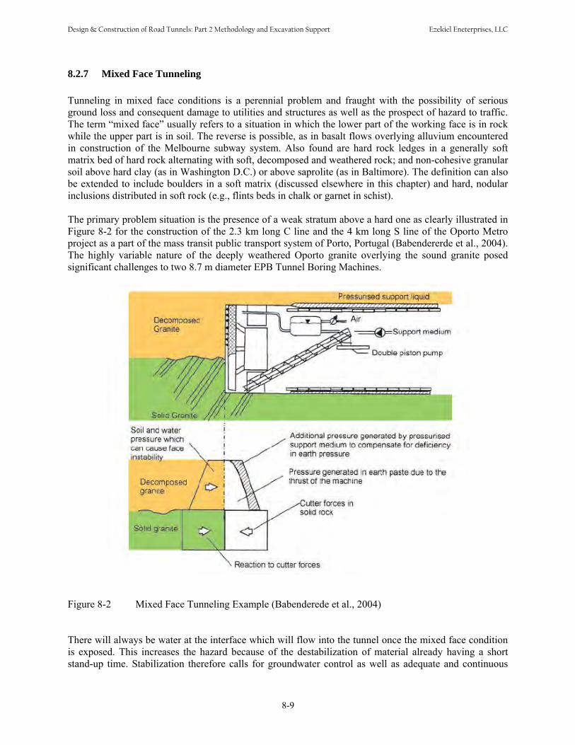
8.2.7 Mixed Face Tunneling
Tunneling in mixed face conditions is a perennial problem and fraught with the possibility of serious ground loss and consequent damage to utilities and structures as well as the prospect of hazard to traffic. The term “mixed face” usually refers to a situation in which the lower part of the working face is in rock while the upper part is in soil. The reverse is possible, as in basalt flows overlying alluvium encountered in construction of the Melbourne subway system. Also found are hard rock ledges in a generally soft matrix bed of hard rock alternating with soft, decomposed and weathered rock; and non-cohesive granular soil above hard clay (as in Washington D.C.) or above saprolite (as in Baltimore). The definition can also be extended to include boulders in a soft matrix (discussed elsewhere in this chapter) and hard, nodular inclusions distributed in soft rock (e.g., flints beds in chalk or garnet in schist).
The primary problem situation is the presence of a weak stratum above a hard one as clearly illustrated in Figure 8-2 for the construction of the 2.3 km long C line and the 4 km long S line of the Oporto Metro project as a part of the mass transit public transport system of Porto, Portugal (Babendererde et al., 2004). The highly variable nature of the deeply weathered Oporto granite overlying the sound granite posed significant challenges to two 8.7 m diameter EPB Tunnel Boring Machines.
Figure 8-2 Mixed Face Tunneling Example (Babenderede et al., 2004)
There will always be water at the interface which will flow into the tunnel once the mixed face condition is exposed. This increases the hazard because of the destabilization of material already having a short stand-up time. Stabilization therefore calls for groundwater control as well as adequate and continuous
8-9
Design & Construction of Road Tunnels: Part 2 Methodology and Excavation Support Ezekiel Eneterprises, LLC
support of the weak material. Moreover, this support must be provided where energetic methods, such as drill-and-blast excavation, are required to remove the harder material. Dewatering can reduce the head of water, but it cannot remove the groundwater completely; nor can it be realistically expected to offer control on an undulating interface with pockets and channels lower than the general elevations established by borehole exploration. Compressed air working will not deal with water in confined lenticular pockets and it is usually inappropriate when the length of the mixed face and soft ground conditions amount to only a few percent of what is otherwise a rock tunnel. Also, recent experience where extensive beds of clean (SP and SP-SM) sands have been major components of the weak ground shows that compressed air alone will not stabilize the ground which becomes free-flowing as soon as it has dried out. Therefore, on the whole, consolidation grouting is to be preferred in this situation. It is emphasized that the best time to seal off groundwater is before it has started to flow into the tunnel. Once the water is flowing, it is extremely difficult to stop it from within the tunnel except by establishing a bulkhead.
8.3 HEAVING LOADING
8.3.1 Squeezing Rock When a tunnel opening is formed, the local stress regime is changed. The radial stress falls to zero and the tangential stresses increase to three times the in situ overburden load (neglecting the effects of any locked-in stress resulting from past tectonic action that has not been relieved). If the unconfined compressive strength of the rock is less than the increased tangential stress, a mode of failure will be initiated which is described as "squeezing rock". As elastic failure occurs, with consequent reduced load-bearing capacity of the ground, the load is transferred by internal shear to adjacent ground until an equilibrium condition is reached. If the ground develops brittle failure and is shed from the tunnel walls, then there will be no residual strength of the failed ground to share in the load redistribution. If the ground is sufficiently weak or the overburden load too great, the unrestrained tunnel may close completely.
8.3.2 The Squeezing Process The detailed mechanism of ground movement is complex and depends on the presence or absence of water and swelling minerals as well as on the physical properties of the ground. For the purposes of this discussion, however, the squeezing process may be described as follows.
8.3.2.1 Initial Elastic Movement As the tunnel is excavated, stress relief allows elastic rebound of ground previously in compression to relieve stress. This stress relief occurs beyond the working face as well as around the tunnel excavation. In thinly laminated rocks such as schist and phyllite, the modulus of elasticity parallel to the foliation is likely to be much higher than that in the perpendicular direction. Therefore, the elastic movement immediately distorts the shape of the excavation as the rock moves a greater distance perpendicular to the foliation than parallel to it. Moreover, since the rock can move more easily along regular foliation planes than perpendicular to them, more than one factor is at work determining the actual distortion of the tunnel shape. The elastic rebound takes place in all tunnel excavations and is not properly a part of squeezing, which is associated with changes in the rock structure. However, the associated increase in tangential stress in the rock initiates the next phase of movement (squeezing) as the rock fails. As the rock moves
8-10
Design & Construction of Road Tunnels: Part 2 Methodology and Excavation Support Ezekiel Eneterprises, LLC
toward the tunnel opening, the circumference of the tunnel shortens. There is a limit imposed by the modulus and strength of the rock on how far this process can continue before elastic failure is initiated. Consider a rock of compressive strength 35 Mpa and an elastic modulus of 17,500 Mpa. The circumferential strain per unit length at failure will be 35/17,500 cm/cm or 2 mm/m. For a tunnel of 2 m radius therefore, a shortening of this radius by about 4 mm implies the initiation of impending elastic failure at the exposed rock surface. This does not mean that the rock suddenly loses all strength (unless it is brittle enough to flake off the wall) but rather that its residual strength is greatly reduced. As the tangential shear stress builds up there will come a time when the differential stress is sufficient to cause internal shear failure. This is manifested by the development of new parting surfaces where the overstressed rock separates from the neighboring rock.
8.3.2.2 Strength Reduction When the rock remaining is insufficiently strong to carry the increased load passed to it as shearing progresses it will fail in turn. In strong and brittle rocks, this failure can result in explosive release of rock fragments from the surface in a phenomenon known as “rock bursting.” A somewhat gentler expression of the same phenomenon is known as “popping rock,” which is still a dangerous phenomenon. Because these occurrences actually remove rock from the surface there is obviously no residual load-carrying capability of the failed rock. In weaker and less brittle rock the failed material stays in place and enters a plastic or elasto-plastic regime. Its modulus of elasticity and its unconfined compressive strength (which represent its load-carrying capacity) may be reduced by two orders of magnitude, but it can still support some load. In the meantime, the load shed by the failed rock at the perimeter of the opening is transferred deeper into the rock mass where the degree of confinement is higher and the ultimate load-bearing capacity is therefore also higher. The phenomenon may be modelled step-wise, but it is truly a continuous process and will cease only when the total load has been redistributed. Depending on the amount of excess load-carrying capacity available in the partially confined rock around the tunnel perimeter, the stress regime may be affected up to several tunnel diameters away from the opening. Compounding the stress increase, which leads to failure, is the similar regime in the dome ahead of the working face. The abutment of this dome is the already overstressed rock behind the working face. The problem is therefore three-dimensional in the region affected. The initial movements associated with strength reduction take place quite fast, so that as much as 30% of the final loss of tunnel size may be completed within one to one and a half tunnel diameters behind the working face.
8.3.2.3 Creep As a consequence of the reduced elastic modulus and the reduced strength of the rock additional radial movement of the tunnel walls occurs. In the zone outside the tunnel, the rock properties are substantially changed. In particular, both the elastic modulus and the unconfined compressive strength decrease continuously (but not in a linear fashion) from their original values still existing in undisturbed rock toward the tunnel wall. The tunnel decreases in diameter as the weakened material creeps toward the tunnel boundary. The rate of movement is roughly proportional to the applied load. The movement is therefore time-dependent (after the initial elastic stress relief, which may be regarded as essentially instantaneous). As the ground is allowed to strain, so the strength of the support required to restrain further movement is reduced. However, depending on the amount of squeezing, shear failures and dilatation accompanying failure may result in unstable conditions in the tunnel walls and crown. Since the timing, location and amount of such failures are not subject to precise definition, support is usually introduced well before the full amount of potential movement has occurred.
8-11
Design & Construction of Road Tunnels: Part 2 Methodology and Excavation Support Ezekiel Eneterprises, LLC
8.3.2.4 Modeling Rock Behavior Because of the nature of the failure mode, elasto-plastic and visco-elasto-plastic mathematical models have been developed to describe the resulting movements and to evaluate the stress regimes for tunnels in rock. These models are not exact but correspond sufficiently well with experience to be useful. Unfortunately, for any given tunnel they depend on the use of information which can only be derived from experience in the specific tunnel involved. This is the origin of the observational approach to tunnel support exemplified by the Sequential Excavation Method (SEM) discussed in Chapter 9. It has been noted from experimental work that the net load appearing at the tunnel surface varies with the tunnel diameter as a power function. The loading is also dependent on the rate of tunnel advance. It is therefore clear that when such conditions are encountered, the smallest tunnel diameter adequate for the purpose should be selected. Experience also shows that circular tunnels are easier to support than any other shape.
8.3.2.5 Other Factors If the rock contains porewater, negative pore pressures are set up as the rock moves toward the tunnel. This provides limited initial support until the negative pore pressure is dissipated. In addition, the new pressure gradient set up by the release of confining pressure results in seepage pressures toward the tunnel boundary. In regions of high hydrostatic head, significant increases in rock loading can occur. It is also thought that even small proportions of swelling clay minerals in the rock can contribute significantly to rock loads when water is present. This water need not be flowing--only present in the pores. When all factors contributing to rock mass behavior have been identified and quantified, it may be possible to develop more exact predictive models and to devise new means for controlling and improving ground behavior. In the meantime, we must make do with approximations based on experience.
8.3.2.6 Monitoring Rate of squeeze and rock loads are somewhat dependent on tunnel size and rate of advance. It is essential in squeezing (or swelling) conditions--or even in blocky and seamy rock where joint closure may create problems--to establish a program of convergence point installations which will be routinely used to monitor the amount and rate of movement of the tunnel walls. This information collected over time and collated with the behavior of the tunnel support system will provide the information needed both to predict and to install the appropriate amount of support as tunneling progresses. This technique lies at the heart of SEM tunneling in rock (Chapter 9). Geotechnical instrumentation is discussed in Chapter 15.
8.3.3 Yielding Supports One approach to squeezing rock is to go to a simple and workable system of yielding supports as illustrated in Figure 8-3. The number of yielding joints can be modified to provide the needs of the rock currently being excavated since all components are manufactured on site. Each joint permits up to 22 cm of closure. (See Figure 8-4) It has been found essential to shotcrete the gaps once the closure nears the limit allowed without the steel sections actually butting together. Failures have been common when this butting has been allowed to happen. It has also been found that allowing the invert to heave freely for twenty to thirty days before making an invert closure allows the total support system to resist all remaining loads with some reserve capacity for long term load increases. Other, more complicated yielding systems have been designed and used.
8-12
Design & Construction of Road Tunnels: Part 2 Methodology and Excavation Support Ezekiel Eneterprises, LLC
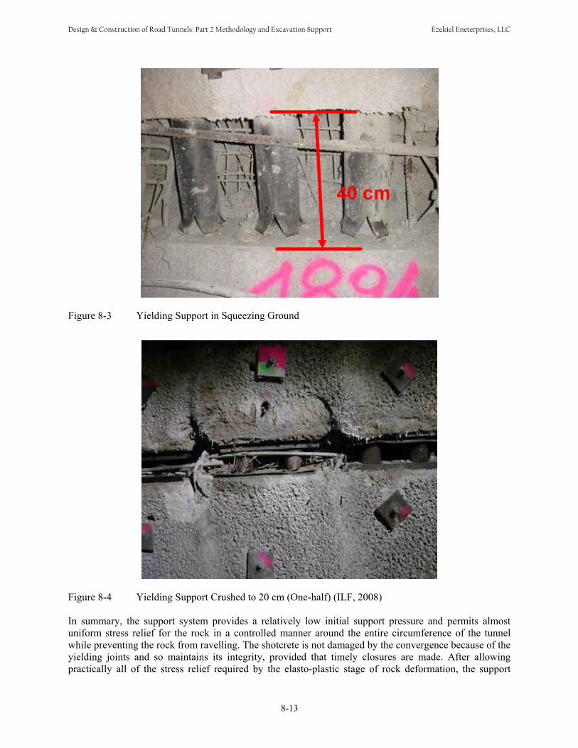
40 cm
Figure 8-3 Yielding Support in Squeezing Ground
Figure 8-4 Yielding Support Crushed to 20 cm (One-half) (ILF, 2008)
In summary, the support system provides a relatively low initial support pressure and permits almost uniform stress relief for the rock in a controlled manner around the entire circumference of the tunnel while preventing the rock from ravelling. The shotcrete is not damaged by the convergence because of the yielding joints and so maintains its integrity, provided that timely closures are made. After allowing practically all of the stress relief required by the elasto-plastic stage of rock deformation, the support
8-13
Design & Construction of Road Tunnels: Part 2 Methodology and Excavation Support Ezekiel Eneterprises, LLC

system is made rigid whence it can support a pressure of 3.8 MPa which is available to deal with long term creep pressure.
8.3.3.1 Timber Wedges and Blocking The use of blocking tightened against the ground by pairs of folding wedges introduces a structural element that can be allowed to fail by crushing. Observation of progressive failure coupled with experience provides warning that the behavior of the steel supports should be closely monitored in case a decrease in spacing or an increase in section becomes necessary.
8.3.3.2 Precast Invert When squeezing is sufficiently severe to be troublesome. it will be seen that the prime tendency is for the lower sidewalls to move in and for the invert to heave. The loss of strength of the rock in the invert leads to the rapid development of muddy and unstable conditions under the tunnel haulage operations. In this case it may be desirable to use precast concrete invert slabs kept up close to the working face in place of invert struts. In one location where high squeezing occurred, such slabs were heaved up and required maintenance to keep the track on grade. However, they did provide a good and trouble-free surface otherwise.
8.3.4 TBM Tunneling Because of the number of large tunnels now under consideration where the use of TBMs is contemplated and where squeezing conditions may become important, the following discussion is extended, even though not based on a great deal of current experience. The majority of examples of tunnels in squeezing ground are related to the crossing of faults. TBMs have been troubled in this situation by inrushes of water carrying sand and finely divided rock or by blocks of rock jamming between the cutters. The second of these problems has been dealt with in many tunnels in otherwise normal conditions. The primary solution is the use of a machine design which allows only a limited projection of the cutters forward of the cutterhead by means of a face shield ahead of the structural support element. The second development is a design which permits worn cutters to be changed from within the tunnel, so that no access is required in front of the cutterhead. There has, as yet, been no easy solution for the problem of the cutterhead and its buckets being choked with sand and rock fragments while unrelenting water flows are in progress. It becomes a difficult and slow process of cleaning out and gaining progress slowly until the affected area has been cleared. Also in such conditions, the presence of a shield is important to protect the machine and to provide temporary support to material with no stand-up time. In some circumstances, if the condition is known to exist or to be likely to exist, probing ahead to identify the precise location can give an opportunity to stabilize the ground with grout injections, keeping a bulkhead thickness ahead of the excavation at all times. It is sometimes possible to allow most of the water to drain out of the ground, but this is not a reliable approach to prediction of construction methods. Shielded TBMs have been used successfully in such conditions, but unfortunately the use of a long shield militates against successful use in squeezing ground. The other major problem, whether or not in a fault or shear zone, is the closure of the ground around the cutterhead shield and any protective shield behind the cutterhead. Many TBMs, have been immobilized because the load on the shield system was too high to permit the machine to advance. One way to approach this problem is by the use of a short shrinkable shield on the machine.
8-14
Design & Construction of Road Tunnels: Part 2 Methodology and Excavation Support Ezekiel Eneterprises, LLC
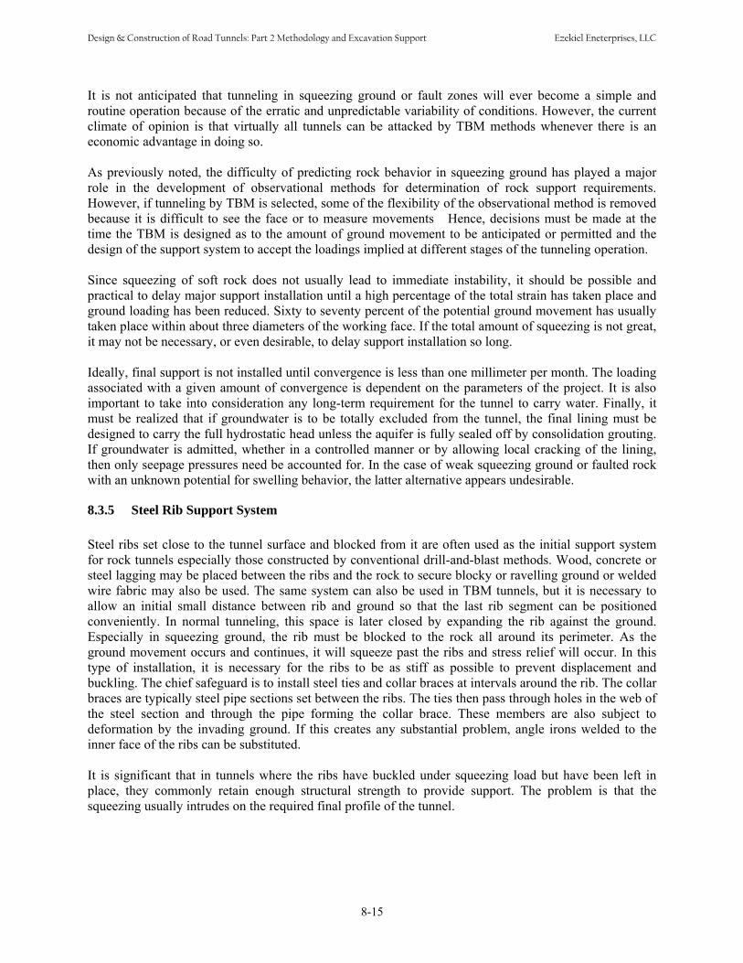
It is not anticipated that tunneling in squeezing ground or fault zones will ever become a simple and routine operation because of the erratic and unpredictable variability of conditions. However, the current climate of opinion is that virtually all tunnels can be attacked by TBM methods whenever there is an economic advantage in doing so. As previously noted, the difficulty of predicting rock behavior in squeezing ground has played a major role in the development of observational methods for determination of rock support requirements. However, if tunneling by TBM is selected, some of the flexibility of the observational method is removed because it is difficult to see the face or to measure movements Hence, decisions must be made at the time the TBM is designed as to the amount of ground movement to be anticipated or permitted and the design of the support system to accept the loadings implied at different stages of the tunneling operation. Since squeezing of soft rock does not usually lead to immediate instability, it should be possible and practical to delay major support installation until a high percentage of the total strain has taken place and ground loading has been reduced. Sixty to seventy percent of the potential ground movement has usually taken place within about three diameters of the working face. If the total amount of squeezing is not great, it may not be necessary, or even desirable, to delay support installation so long. Ideally, final support is not installed until convergence is less than one millimeter per month. The loading associated with a given amount of convergence is dependent on the parameters of the project. It is also important to take into consideration any long-term requirement for the tunnel to carry water. Finally, it must be realized that if groundwater is to be totally excluded from the tunnel, the final lining must be designed to carry the full hydrostatic head unless the aquifer is fully sealed off by consolidation grouting. If groundwater is admitted, whether in a controlled manner or by allowing local cracking of the lining, then only seepage pressures need be accounted for. In the case of weak squeezing ground or faulted rock with an unknown potential for swelling behavior, the latter alternative appears undesirable.
8.3.5 Steel Rib Support System Steel ribs set close to the tunnel surface and blocked from it are often used as the initial support system for rock tunnels especially those constructed by conventional drill-and-blast methods. Wood, concrete or steel lagging may be placed between the ribs and the rock to secure blocky or ravelling ground or welded wire fabric may also be used. The same system can also be used in TBM tunnels, but it is necessary to allow an initial small distance between rib and ground so that the last rib segment can be positioned conveniently. In normal tunneling, this space is later closed by expanding the rib against the ground. Especially in squeezing ground, the rib must be blocked to the rock all around its perimeter. As the ground movement occurs and continues, it will squeeze past the ribs and stress relief will occur. In this type of installation, it is necessary for the ribs to be as stiff as possible to prevent displacement and buckling. The chief safeguard is to install steel ties and collar braces at intervals around the rib. The collar braces are typically steel pipe sections set between the ribs. The ties then pass through holes in the web of the steel section and through the pipe forming the collar brace. These members are also subject to deformation by the invading ground. If this creates any substantial problem, angle irons welded to the inner face of the ribs can be substituted. It is significant that in tunnels where the ribs have buckled under squeezing load but have been left in place, they commonly retain enough structural strength to provide support. The problem is that the squeezing usually intrudes on the required final profile of the tunnel.
8-15
Design & Construction of Road Tunnels: Part 2 Methodology and Excavation Support Ezekiel Eneterprises, LLC

8.3.6 Concrete Segments Segmental concrete linings take two quite different forms. The traditional bolted and gasketted lining is meant to be a final lining erected in one pass. Until recently, the more common application has been to use unbolted, ungasketted segments, with light reinforcement to allow handling, as a “sacrificial: primary lining. This latter type of lining is sacrificial only in the sense that it is allowed to sustain fractures resulting from jacking loads or redistribution of stress; it retains most of its initial load-bearing capacity. A final lining is always placed within this type of lining; it sometimes is an unreinforced concrete lining of nominal thickness, say 10 inches. The combination lining may be less expensive than the one-pass system and has the merit of flexibility. Problems arose with the precast concrete tunnel lining when there was insufficient erection space to allow for deviations normal to tunneling. In electing to use a precast concrete lining decisions are necessary as to the amount of ground movement to be allowed and the backfill material to be used between the lining and the rock. In allowing for a large amount of potential ground movement, certain problems of erection stability arise. The lining will require support clear of the invert and a horizontal tie or blocking to keep it in shape during and after erection until backfill grouting is complete. There is time and skill involved in executing the work, but no significant difficulty. Current technology is now trending towards the use of a one pass system of concrete segments. These segments are of high quality concrete and are usually bolted and gasketed at all joints. However, specially doweled circumferential joints are being used. It is necessary that such rings be cast and cured in a controlled factory environment and that they be of high strength concrete for high resistance and high elastic modulus. Steel fibers may be used in lieu of reinforcing steel in some applications. It is important that the moving ground should not come into contact with the completed ring at a point. Distortion would necessarily result with a possible consequence of reducing load-bearing capacity. It is also possible to use compressible backfill in the annular void provided the material offers sufficient resistance to mobilize passive reactions sufficient to withstand distortion of the lining. At the least, careful consideration would be needed in specifying the strength and deformability of any compressible material to be used.
8.3.7 TBM Tunneling System The principal components of a TBM affected by the difference between tunneling in squeezing and non-squeezing ground are discussed below. Chapter 6 presents major components and back up system for a tunnel boring machine.
8.3.7.1 Cutterhead Many different cutterhead designs have been used over the years from the earliest flat heads with multiple disc cutters through domed heads, rounded edge flat heads and conical designs. These days the cutterhead geometry is selected on the basis of the ground it is expected to penetrate. It has been found preferable to arrange that at least the gauge cutters be designed to be changed from behind and it is now common to arrange this system for all cutters. A spoke design allows ready access to the working face and simplifies design in some respects. However, such machines offer little support if weak ground is encountered and it is generally considered prudent to use a closed face machine. Also, to protect the cutters and cutter mounts, a lighter false face is provided so that the cutter disks protrude only a short distance.
8-16
Design & Construction of Road Tunnels: Part 2 Methodology and Excavation Support Ezekiel Eneterprises, LLC
In conventional designs, the cutterhead is provided with its own shield as part of the cutterhead bucket system. The conventional design creates a drum about 4 feet (1.2 m) long almost in contact with the ground. In squeezing ground this shield is vulnerable to the pressure exerted by rock movement. It is therefore better that the shield be smaller in diameter than the excavation and that it be tapered toward the rear. The gauge cutters should be arranged to protrude beyond the main body of the cutterhead. If the cutterhead is not in close contact with the ground, provision must be made to provide stable support in its place. This will be the equivalent of a sole plate as used for overcutter compensation in earth pressure balance machines. However, in order to provide for varying amounts of overcut, the support will need to be hydraulically actuated. Since it will be subjected to substantial shear loading, the design will have to be very stiff.
8.3.7.2 Propulsion A TBM requires a reaction against which to propel itself forward. This reaction can be obtained by shoving directly against the tunnel support system with jacks spaced around the perimeter of the machine or by developing frictional resistance against the tunnel sidewalls. The thrust needed to keep the cutterhead moving forward is about 25,000 kg per cutter. When the ground is weak, it is desirable to limit the bearing pressure on the tunnel walls because the weak rock would fail under even light loads, especially perpendicular to the direction of foliation. This would accelerate the rate of squeezing and might increase the total strain. At the same time it would be desirable to limit the length occupied by the grippers so as to minimize the necessary distance between the working face and any support system. This would probably require that there be multiple grippers covering most of the circumference but of limited length to minimize uneven bearing on the squeezing rock surface.
8.3.7.3 Shield If any shield is felt to be desirable or necessary, it should be short and shrinkable. Many TBMs have been stuck because the ground has moved on to the shield and exerted sufficient load to stall the machine.
8.3.7.4 Erector It is desirable to have complete flexibility in selecting the point at which ring erection is to take place. Therefore the erector should be free to move along the tunnel, mounted on the conveyor truss. A ring former should also be used to maintain the shape of the last erected ring until it has been grouted if concrete segmental lining is used.
8.3.7.5 Spoil Removal Conventional conveyor to rail car systems or single conveyor systems designed for the tunnel size selected are appropriate.
8.3.7.6 Back-Up System In order to keep the area between the grippers and the ring erection area as clear as possible, any ancillary equipment such as transformers, hydraulic pumps etc. should be kept clear of this space at track level.
8-17
Design & Construction of Road Tunnels: Part 2 Methodology and Excavation Support Ezekiel Eneterprises, LLC
8.3.8 Operational Flexibility It is envisaged that the system outlined above would be capable of handling either steel ribs or precast concrete supports. If shoving off the supports were to be selected for TBM propulsion, the degree of flexibility would be less than with the use of a gripper system. It would also be more vulnerable to problems in any circumstance where the convergence rate was markedly higher than expected.
8.3.9 Swelling Swelling phenomena are generally associated with argillaceous soils or rocks derived from such soils. In the field, it is difficult to distinguish between squeezing and swelling ground, especially since both conditions are often present at the same time. However, except in extreme conditions, squeezing is almost always self-limiting and will not recur vigorously, or at all, once the intruding material has been removed; while swelling may continue as long as free water and swelling minerals are present especially when the intruding material has been removed, thereby exposing fresh, unhydrated rock. Many European rail and highway tunnels are constructed in formations noted for their susceptibility to swelling. Most construction involves a more or less circular wall and roof section with an invert slab having a greater radius of curvature. Some of them are still being periodically repaired a century after construction. It has been noted in this connection that as the invert arches are excavated and replaced to more nearly circular configurations, the greater the time that elapses before the next repair is necessary. Expansive clays are more common in younger argillaceous rocks, the proportions ranging from 65% in Pliocene and Miocene age material to only 5% in Cambrian and Precambrian. Montmorillonite is found in rocks of all ages as thin partings or thicker beds. Sodium montmorillonite is much more expansive than calcium montmorillonite.
8.3.10 Swelling Mechanism Most swelling is due to the simultaneous presence of unhydrated swelling clay minerals and free water. Tunnel construction commonly creates these conditions. Minerals such as montmorillonite form layered platy crystals; water may be taken up in the crystal lattice with a resultant increase in volume of up to ten times the volume of the unhydrated crystal. The displacements resulting from this increase in volume give rise to the observed swelling pressures, whether in soil or in rock. If possible water should be kept away from rock or soil containing swelling clay minerals; however, it must be realized that water from fresh concrete, water vapor from a humid atmosphere or pore water released from confinement within the rock will initiate the swelling process. Since the swelling will not passivate in the same way as squeezing generally will in rock, tunnel support must be designed to resist the swelling pressure (which can be measured in the laboratory), even if it proves possible to let some swelling take place without creating problems.
8.3.11 Other Rock Problems Schists commonly contain clay minerals such as biotite, mica and chlorite. All of these are platy minerals and are found aligned with the foliation. If present as continuous layers, they have to be considered planes of weakness when assessing questions of rock stability. Similarly, weathered material in shears and mylonite not yet weathered indicate planes of weakness. Anhydrite converts to gypsum in the presence of water with a volume increase of up to 60% accompanying the conversion. However, beds of anhydrite are not affected in the same way as finely
8-18
Design & Construction of Road Tunnels: Part 2 Methodology and Excavation Support Ezekiel Eneterprises, LLC
divided rock since the reaction does not penetrate below the surface. However, if the anhydrite is fractured, the conversion will proceed faster and faster as more fracturing is developed by the expansive reaction. The actual amount of expansion will depend upon the void ratio of the anhydrite. As with other water-sensitive minerals, every effort should be made to keep water away from anhydrite. This may be a particular problem when fluid transport tunnels are being constructed since any leakage will result in major damage to the tunnel.
8.4 OBSTACLES AND CONSTRAINTS
8.4.1 Boulders Practical experience of the value of cutterhead disks in such a situation was first developed in Warrington, England. A slurry shield was to be used for a tunnel originally expected to be in soils. A late decision to change the alignment because of local constraints forced the tunnel into an area where boulders and sandstone bedrock would be encountered in the invert. Since the equipment was already built, disk cutters were added to the head in the hope that they would solve the unexpected problem. These hopes were fulfilled. More recent investigation in Japan has indicated from experimental models that even very soft clay will provide sufficient support to hold boulders in place so that they are broken up by the action of disk cutters. On the other hand, rotary head excavators of various general designs have failed to deal successfully with boulders when drag picks were relied on. A particular difficulty sometimes occurs when boulder beds are encountered which have saturated fine silt in the void spaces between the boulders. This problem seems to be most often encountered in regions which have been subjected to glaciation. The loss of ground associated with flow of the saturated fines into the tunnel does not normally result in ground settlement, because the movement of any other material replacing the lost fines will generally be choked off. If this is not the case, or if it is felt undesirable to leave such voids unfilled, various courses of action are available. Compressed air working will drive water out of the silt and thereby stabilize it, provided that the boulder bed is not confined within impervious material. In such a case, compressed air working will not be very effective. The use of an EPB fitted with disk cutters will be effective provided that the pressure in the plenum chamber is kept at a level high enough to balance the hydrostatic head in the silt. Slurry shield operation with the same restrictions would be even more effective, but at a higher cost. As a last resort, consolidation or replacement grouting may be employed behind the shield. The choice of method will depend on economics, as is often the case when selecting a construction method. If the condition exists in only a small part of a long tunnel, less efficient means may be selected for dealing with the boulder bed--even including local cut-and-cover work, if the tunnel is not too deep or the water table too high. In any case, full breasting of the face is required if the boulders are not in intimate contact with one another. It is conceivable that grout could be injected into the working face at a distance behind it so as to force out the flowing material. For such a program to be effective, it would be necessary to grout multiple points simultaneously so as to avoid development of a preferred path for escaping fines. The grout would also have to extend outside the tunnel perimeter for a sufficient distance to establish a plug which could be excavated without developing problems behind the shield. However, it must be said that in small tunnels, access for implementation of such a program is unlikely to be available.
8.4.2 Karstic Limestone Karstic limestone is often riddled with solution cavities of various sizes. Depending on the geologic history of the locale in which it is found, cavities ahead of the excavation may be filled with water, mud
8-19
Design & Construction of Road Tunnels: Part 2 Methodology and Excavation Support Ezekiel Eneterprises, LLC
or gravel or a combination of these. Flowing water may be present in large quantities. There may be an insufficient thickness of sound rock at tunnel elevation to provide safe support for tunneling equipment. All of these possibilities point out the need for thorough exploration before undertaking tunnel construction in limestone, particularly in an area where there is no prior history of underground construction or mining.
8.4.3 Abandoned Foundations Abandoned foundations or other facilities, are to be expected in urban tunnels. To illustrate, on one project 898 piles were encountered during construction of rapid transit tunnels in an urban area. This was more than double the highest estimate. These piles were mostly unrecorded relics of earlier construction abandoned after fires which regularly ravaged the area during the late 19th century as well as piles left behind by successive reclamation operations, which moved the waterfront several hundred meters into the bay over a few decades. All but two of the piles were timber; they were removed by cutting them into short lengths as they were exposed in the face of the shield using a hydraulically powered beaver-tail chain saw purpose-made for the job. The other two posed a different problem. One was concrete and the other steel. Since the tunnel was being constructed in compressed air, both burning the steel and breaking the concrete were non-trivial problems. Removal of these piles took about 10 times as long as removal of the timber piles. With a TBM, similarly, the wood piles can be cut by the disk cutters but a similar increase in time would be expected for the steel and concrete piles. As an additional problem, the lengths of pile left in place above the tunnel eventually crept downward as they sought to carry the weight of soil adhering to them as well as the artificial fill above. In a number of places it was necessary to reinforce the skin of the fabricated steel liner plates which were dimpled by the point loads exerted. A second illustrative project involved construction of a storm drainage tunnel. For a short distance at the downstream portal, the tunnel was in soil; because of its short length it was driven without a shield. Since the soil was largely, if not entirely, fill, it proved difficult to maintain the tunnel shape until steel ribs were introduced between alternate rings of liner plate. It was known that old mill foundations lay ahead, but their location was uncertain. It was therefore deemed prudent to continue this tunneling method into the sandstone ahead for at least a short distance. During the drive, some of the foundations were found in the soil tunnel. Careful breasting to isolate the concrete was successful in controlling soil movement while the concrete was broken out. With the next advance of normal tunneling, the voids were promptly and completely filled and there was no encroachment on the tunnel profile. It would be possible to multiply examples endlessly, but the key to all such problems is to gather the maximum available information, project the worst scenario and be prepared to deal with it as an engineering rather than an economic problem.
8.4.4 Shallow Tunnels The problem with shallow tunnels is that side support is not reliable and loading on the support system is far from the usual comfortable assumption of essentially uniform radial load. It is quite common in urban situations to be restricted by the presence of significant structures--whether on the surface or underground. Consolidation grouting has been used where ground conditions are favorable and compaction grouting has also been used successfully to avoid the need for underpinning. In other cases; jet grouting, pipe canopies or other spiling may be appropriate. It is not practical to define the range of conditions leading to selection of any particular solution, since all such projects tend to have unique
8-20
Design & Construction of Road Tunnels: Part 2 Methodology and Excavation Support Ezekiel Eneterprises, LLC
features. Sequential excavation method (Chapter 9), cut and cover method (Chapter 5) and/or jacked box tunneling method (Chapter 12) can be considered as well.
8.5 PHYSICAL CONDITIONS
8.5.1 Methane Methane is commonly found where organic matter has been trapped below or within sedimentary deposits, whether or not they have yet been lithified. It is particularly common in the shaley limestones around the Great Lakes; in hydrocarbon--whether coal or oil-- deposits in Pennsylvania, West Virginia, Colorado or California and in many other localities. It should be noted here that “methane” is commonly used as a denotation of all of the ethane series that may be present, although methane is distinguished as the major component usually present. It is also the only member substantially lighter than air. Methane forms an explosive mixture when mixed with air and between about 5 and 15% of the total volume is methane. It is readily diluted and flushed from a tunnel by ventilation when encountered in the quantities that are normally expected. Safety rules require that action be taken when methane is present in concentrations of 20% of the lower explosive limit. For practical purposes, this means a concentration of 1% by volume. It is necessary to use routine testing to determine whether or not explosive gasses are present. This testing is carried out in all tunnels identified as being gassy or potentially gassy. A positive rating of non-gassy is required to relieve the contractor of the duty to test, although in many localities it is deemed prudent to continue testing on a reduced schedule even though no gas has been identified in the tunnel excavation.
8.5.2 Hydrogen Sulfide Hydrogen sulfide is present in association with methane often enough that its presence should always be suspected in gassy conditions. Its presence is easily identified in low concentrations by its typical rotten egg smell. It is a cumulative poison and deadly in low concentrations; a whiff at 100 percent concentration is generally instantly fatal. It should also be noted that, when hydrogen sulfide is present in low concentrations, the nose becomes desensitized to its presence. Apart from testing and maintenance of high volume ventilation, signs of its presence follow a sequence of headaches, coughing, nausea and unconsciousness. Concentrations should be limited to 10 ppm or less (depending on local regulations) of eight hour exposures. Meticulous attention to ventilation, especially in work areas, is required when hydrogen sulfide is present or suspected. As with methane, ventilation must be maintained at high volumes for dilution 24 hours a day, 7 days a week, regardless of whether work is in progress or not. Even so, no shaft, pit or tunnel or other opening below grade should be entered without first testing the air. This is especially important if the purpose of entering is to repair a defective fan. Where possible, the gas should be extracted directly and discharged into the ventilation system without ever entering the tunnel atmosphere.
8.5.3 High Temperatures The geothermal gradient is different in different localities within a range of about 2:1. As a rule of thumb, one degree Celsius per 100 meters of depth will be a reasonable guide. Where the tunnel is comparatively shallow--say less than about 150 m--there will be little effect. In fact, it will be found that the tunnel temperature is the average year-round temperature at that location.
8-21
Design & Construction of Road Tunnels: Part 2 Methodology and Excavation Support Ezekiel Eneterprises, LLC

Nevertheless, especially in areas of volcanism or geothermal activity or tropical temperatures, the temperature in deep tunnels can rise to body heat or higher. If hot water flows are present or if the tunnel is very humid (which is more common than not), conditions can be actively dangerous as sweating and evaporation are inhibited; heat stroke can be induced in such conditions. The only factor that can be directly controlled is the tunnel ventilation. By supplying air at a lower temperature, the local conditions can be kept bearable, especially if the incoming air is dry enough to accept evaporating moisture.
8.5.4 Observations The significant effects and the construction problems resulting from the various difficult tunneling conditions discussed above make it clear that all of the possibilities associated with the geology and occupational history of the region in which new tunneling is contemplated need to be borne in mind from the construction as well as the design standpoint when the preliminary and final geotechnical exploration and testing programs are designed. It is important that engineers designing a tunnel project develop a full understanding of the nature of the ground conditions affecting the construction; so that not only the field investigation but also the design development, specifications and geotechnical reports reflect a full understanding of the problems and the variety of potential approaches to their solution. In the end, the project owner's interests will be best served by thoughtful analysis and full disclosure of conditions and of the solutions foreseen, and of the underlying design approach rather than by avoiding the recognition of problems and their potential impact.
8-22
Design & Construction of Road Tunnels: Part 2 Methodology and Excavation Support Ezekiel Eneterprises, LLC
Appendix C
Cut-and-Cover Tunnel Design Example
Design & Construction of Road Tunnels: Part 2 Methodology and Excavation Support Ezekiel Eneterprises, LLC
APPENDIX C - EXAMPLE CUT AND COVER BOX TUNNEL
The purpose of this design example is to provide guidance to the application of the AASHTO LRFDBridge Design Specifications when designing concrete cut and cover box tunnel structures.
Reference is made to the AASHTO LRFD specifications throughout the design example. Specificreferences to sections are denoted by the letter "S" preceeding the specification article.
C-1
Design & Construction of Road Tunnels: Part 2 Methodology and Excavation Support Ezekiel Eneterprises, LLC

1. Tunnel Section Geometry and MaterialsThe tunnel is a reinforced concrete double-chamber box structure. It is located entirely below grade andis built using cut and cover construction. Because the water table is located above the tunnel,hydrostatic soil pressures surround the structure. Figure 1 shows the internal dimensions for one of theopenings. These dimensions serve as the starting point for the structural dimensions shown in Figure 2.
Figure 1
1.1 Tunnel Section Dimensions
Box interior width, x = 35.75 ftBox interior height, y = 20.00 ftInterior wall thickness= 1.00 ftExterior wall thickness = 2.00 ftBottom slab thickness = 1.75 ftTop slab thickness = 2.50 ftSoil depth, Z1 = 10.00 ftWater depth, Z2 = 5.00 ftTotal depth, D = 34.25 ftBox total width, B = 76.50 ftWidth between centroids of exterior walls, B1 = 74.50 ftBox total height, H = 24.25 ftHeight between centroids of slabs, H1 = 22.13 ft
Figure 2 shows the geometry of the underground cut and cover box cross-section.
C-2
Design & Construction of Road Tunnels: Part 2 Methodology and Excavation Support Ezekiel Eneterprises, LLC
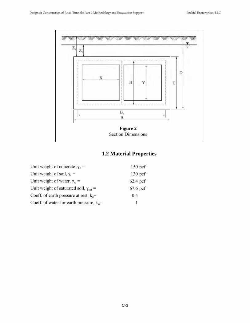
1.2 Material Properties
Unit weight of concrete , c = 150 pcfUnit weight of soil, s = 130 pcfUnit weight of water, w = 62.4 pcfUnit weight of saturated soil, sat = 67.6 pcfCoeff. of earth pressure at rest, ko= 0.5Coeff. of water for earth pressure, kw= 1
C-3
Figure 2Section Dimensions
Design & Construction of Road Tunnels: Part 2 Methodology and Excavation Support Ezekiel Eneterprises, LLC
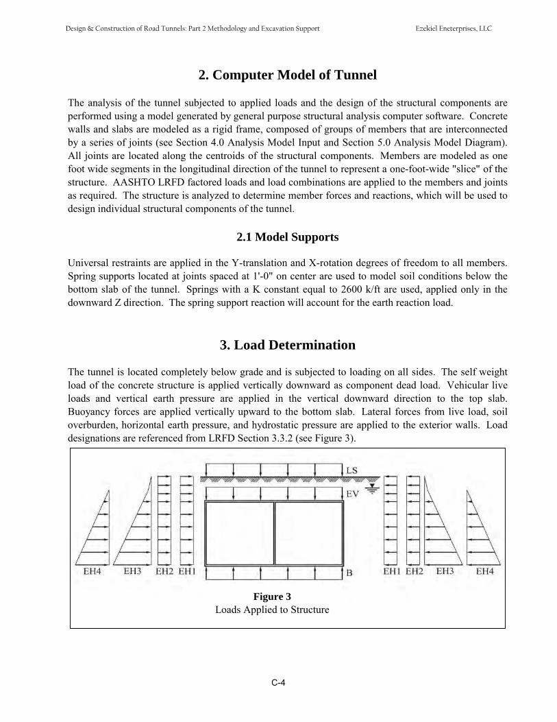
2. Computer Model of Tunnel
The analysis of the tunnel subjected to applied loads and the design of the structural components areperformed using a model generated by general purpose structural analysis computer software. Concretewalls and slabs are modeled as a rigid frame, composed of groups of members that are interconnectedby a series of joints (see Section 4.0 Analysis Model Input and Section 5.0 Analysis Model Diagram).All joints are located along the centroids of the structural components. Members are modeled as onefoot wide segments in the longitudinal direction of the tunnel to represent a one-foot-wide "slice" of thestructure. AASHTO LRFD factored loads and load combinations are applied to the members and jointsas required. The structure is analyzed to determine member forces and reactions, which will be used todesign individual structural components of the tunnel.
2.1 Model Supports
Universal restraints are applied in the Y-translation and X-rotation degrees of freedom to all members.Spring supports located at joints spaced at 1'-0" on center are used to model soil conditions below thebottom slab of the tunnel. Springs with a K constant equal to 2600 k/ft are used, applied only in thedownward Z direction. The spring support reaction will account for the earth reaction load.
3. Load Determination
The tunnel is located completely below grade and is subjected to loading on all sides. The self weightload of the concrete structure is applied vertically downward as component dead load. Vehicular liveloads and vertical earth pressure are applied in the vertical downward direction to the top slab.Buoyancy forces are applied vertically upward to the bottom slab. Lateral forces from live load, soiloverburden, horizontal earth pressure, and hydrostatic pressure are applied to the exterior walls. Loaddesignations are referenced from LRFD Section 3.3.2 (see Figure 3).
Figure 3Loads Applied to Structure
C-4
Design & Construction of Road Tunnels: Part 2 Methodology and Excavation Support Ezekiel Eneterprises, LLC

3.1 Total Dead Loads
Dead loads are represented by the weight of all components of the tunnel structure and the vertical earthpressure due to the dead load of earth fill.
Concrete dead load (per foot length) (DC)Top slab = 0.15 ksf × (76.5 × 2.5) = 28.69 kipBottom slab = 0.15 ksf × (76.5 × 1.75) = 20.08 kipInterior wall = 0.15 ksf × (1 × 20) = 3.00 kipExterior walls (2) = 0.15 ksf × 2 × (2 × 20) = 12.00 kip
Vertical earth pressure (EV)EV= 1.30 ksfSoil wt = 1.30 ksf × 76.50 = 99.45 kip
3.2 Live Load
Live load represents wheel loading from an HS-20 design vehicle. It is assumed that the wheels act aspoint loads at the surface and are distributed downward in both directions through the soil to the top slabof the tunnel. The load distribution is referenced from LRFD Section 3.6.1.2.6. Figure 4 shows thedistribution of the wheel loads to the top slab.
Figure 4Live Load Distribution
Wheel Loads (LL) 4kLL1 2 0.04 ksf (S3.6.1.2.6)(z1 )
16kLL2 2 0.16 ksf controls(z1 )
C-5
Design & Construction of Road Tunnels: Part 2 Methodology and Excavation Support Ezekiel Eneterprises, LLC

Live Load Surcharge (LS)
LS = 0.16 × 76.50 = 12.240 kip
Surch. Ht = Max(qw1, qw2) = 1.231 ft s
3.3 Lateral Earth Pressure EH1, EH2, EH3, EH4
Lateral earth pressure is typically represented by the equation:
= k0 n
The following lateral pressures are applied to the exterior walls of the tunnel (see Figure 5):EH1 = LL surchargeEH2 = Lateral earth pressure due to soil overburdenEH3 = Horizontal earth pressureEH4 = Hydrostatic pressure
Figure 5Lateral Earth Pressure Distribution
C-6
Design & Construction of Road Tunnels: Part 2 Methodology and Excavation Support Ezekiel Eneterprises, LLC

Calculate the lateral earth pressures:
EH1 = ko s×nsurch) = 0.080 ksf
EH2 = ko s×ns + sat×nsat) = 0.494 ksfns = 5.00 ft
nsat = 5.00 ft
EH3= ko s×ns + sat×nsat) = 1.314 ksfns = 5.00 ft
nsat = 29.25 ft
EH4 = kw w×nw) = 1.825 ksfnw = 29.25 ft
3.4 Buoyancy Load WA
Area of water displaced, AA = B × H = 1855.125 sq. ft.
Buoyancy = A × w = 115.76 klf (along tunnel) OK
WA = Buoyancy = 1.513 klfB
C-7
Design & Construction of Road Tunnels: Part 2 Methodology and Excavation Support Ezekiel Eneterprises, LLC
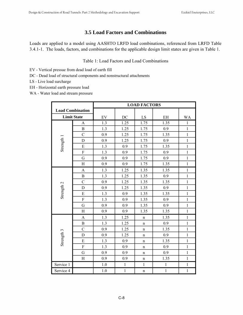
3.5 Load Factors and Combinations
Loads are applied to a model using AASHTO LRFD load combinations, referenced from LRFD Table3.4.1-1. The loads, factors, and combinations for the applicable design limit states are given in Table 1.
Table 1: Load Factors and Load Combinations
EV - Vertical pressue from dead load of earth fillDC - Dead load of structural components and nonstructural attachmentsLS - Live load surchargeEH - Horizontal earth pressure loadWA - Water load and stream pressure
Load CombinationLOAD FACTORS
EV DC LS EH WALimit State
Stre
ngth
1
A 1.3 1.25 1.75 1.35 1B 1.3 1.25 1.75 0.9 1C 0.9 1.25 1.75 1.35 1D 0.9 1.25 1.75 0.9 1E 1.3 0.9 1.75 1.35 1F 1.3 0.9 1.75 0.9 1G 0.9 0.9 1.75 0.9 1H 0.9 0.9 1.75 1.35 1
Stre
ngth
2
A 1.3 1.25 1.35 1.35 1B 1.3 1.25 1.35 0.9 1C 0.9 1.25 1.35 1.35 1D 0.9 1.25 1.35 0.9 1E 1.3 0.9 1.35 1.35 1F 1.3 0.9 1.35 0.9 1G 0.9 0.9 1.35 0.9 1H 0.9 0.9 1.35 1.35 1
Stre
ngth
3
A 1.3 1.25 n 1.35 1B 1.3 1.25 n 0.9 1C 0.9 1.25 n 1.35 1D 0.9 1.25 n 0.9 1E 1.3 0.9 n 1.35 1F 1.3 0.9 n 0.9 1G 0.9 0.9 n 0.9 1H 0.9 0.9 n 1.35 1
Service 1 1.0 1 1 1 1Service 4 1.0 1 n 1 1
C-8
Design & Construction of Road Tunnels: Part 2 Methodology and Excavation Support Ezekiel Eneterprises, LLC
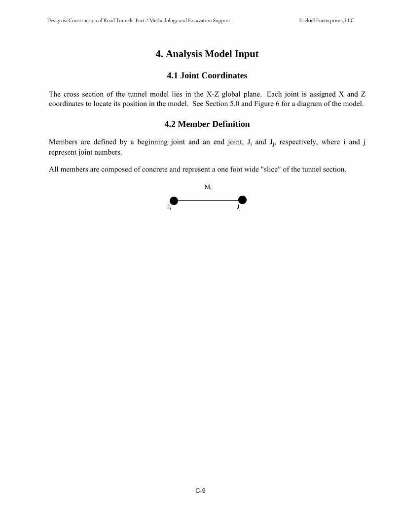
4. Analysis Model Input
4.1 Joint Coordinates
The cross section of the tunnel model lies in the X-Z global plane. Each joint is assigned X and Zcoordinates to locate its position in the model. See Section 5.0 and Figure 6 for a diagram of the model.
4.2 Member Definition
Members are defined by a beginning joint and an end joint, Ji and Jj, respectively, where i and jrepresent joint numbers.
All members are composed of concrete and represent a one foot wide "slice" of the tunnel section.
Mi
Ji Jj
C-9
Design & Construction of Road Tunnels: Part 2 Methodology and Excavation Support Ezekiel Eneterprises, LLC

Joints 302, 402, and 502 at the base of the exterior walls and joints 305, 405, and 505 at the top of theexterior walls are included to determine shear at the face of the top and bottom slabs.
C-10
5. Analysis Model Diagram
The computer model represents a one foot wide slice of the cross-section of the tunnel. Members areconnected by series of joints at their endpoints to form a frame, and are located along the centroids ofthe walls and roof and floor slabs. Joints in the 100 series and 200 series represent the floor and roofslabs respectively. Joints in the 300 and 500 series represent the exterior walls, while the 400 seriesrepresents the interior wall. The bottom diagram of Figure 5 shows all joints in the structure, while thetop diagram shows only the joints at the intersections of slabs and walls.
Figure 6Centroid of the Frame and Joint
Design & Construction of Road Tunnels: Part 2 Methodology and Excavation Support Ezekiel Eneterprises, LLC

6. Application of Lateral Loads (EH)
Lateral pressures EH1 through EH4 from Section 3.3 are applied to the members of the model as shownbelow. See Figure 7 for the horizontal earth pressure and hydrostatic pressure load distributions.
6.1 Exterior Wall Loads Due to Horizontal Earth Pressure EH3
Calculate pressure at top of wall:
ko s×ns + sat×nsat) = 0.494 ksf51000
6.675
1000130
5.0
Pressure at base of wall = 1.314 ksf (see calculation in Sec. 3.3)
Calculate interval increment for loading all exterior wall members:
0.164 ksf5
)49.031.1(
The two tables below show the lateral earth pressure values (ksf) at the beginning and end of eachmember of the exterior walls:
Member start end301 1.31 1.15302 1.15 0.99303 0.99 0.82304 0.82 0.66305 0.66 0.49
Member start end501 -1.31 -1.15502 -1.15 -0.99503 -0.99 -0.82504 -0.82 -0.66505 -0.66 -0.49
C-11
Design & Construction of Road Tunnels: Part 2 Methodology and Excavation Support Ezekiel Eneterprises, LLC
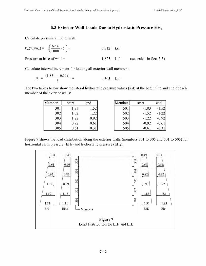
6.2 Exterior Wall Loads Due to Hydrostatic Pressure EH4
Calculate pressure at top of wall:
kw w×nw) = 0.312 ksf5100062.41
Pressure at base of wall = 1.825 ksf (see calcs. in Sec. 3.3)
Calculate interval increment for loading all exterior wall members:
0.303 ksf50.31)(1.83
The two tables below show the lateral hydrostatic pressure values (ksf) at the beginning and end of eachmember of the exterior walls:
Member start end301 1.83 1.52302 1.52 1.22303 1.22 0.92304 0.92 0.61305 0.61 0.31
Member start end501 -1.83 -1.52502 -1.52 -1.22503 -1.22 -0.92504 -0.92 -0.61505 -0.61 -0.31
Figure 7 shows the load distribution along the exterior walls (members 301 to 305 and 501 to 505) forhorizontal earth pressure (EH3) and hydrostatic pressure (EH4).
EH4Figure 7Load Distribution for EH3 and EH4
C-12
Design & Construction of Road Tunnels: Part 2 Methodology and Excavation Support Ezekiel Eneterprises, LLC

7. Structural Design Calculations - General Information
7.1 Concrete Design Properties
Modulus of elasticity of steel, Es = 29000 ksiYield strength of steel reinforcement, fy = 60 ksiCompressive strength of concrete, f'c = 4 ksi
7.2 Resistance Factors
Resistance factors for the strength limit state using conventional concrete construction are referencedfrom AASHTO LRFD Section 5.5.4.2.
Flexure = 0.90 ( ) varies from 0.75 to 0.9 (0.75 is conserverative)Shear = 0.90Compression = 0.7 since no spirals or ties
8. Interior Wall Design
8.1 Factored Axial Resistance (S5.7.4.4)
For members with tie reinforcement using LRFD eq. (5.7.4.4-3): P = 0.80 [0.85×f'
n c×(Ag - Ast) + fy×Ast]Where:A 2
st = 1.76 in (#6 at 6", ea. face)A = 144.00 in2
g
Where Ag= 12·12 in2 (assuming wall thickness = 1 foot)Pn = 471.37 kip
Factored axial resistance of reinforced concrete using LRFD eq. (5.7.4.4-1):Pr = Pn = 0.9 for flexure
Where:Pr = factored axial resistancePn = nominal axial resistancePu = factored applied axial force
Pr = 424.24 kipCheck Pu < Pr
Pu = from computer model output = 78.00 kip < Pr OK
C-13
Design & Construction of Road Tunnels: Part 2 Methodology and Excavation Support Ezekiel Eneterprises, LLC
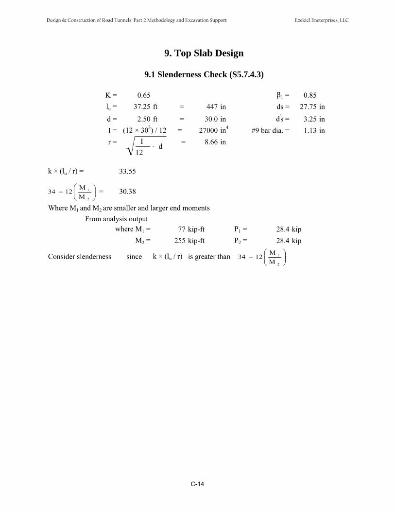
9. Top Slab Design
9.1 Slenderness Check (S5.7.4.3)
K = 0.65 1 = 0.85lu = 37.25 ft = 447 in ds = 27.75 in
d = 2.50 ft = 30.0 in d's = 3.25 inI = (12 × 303) / 12 = 27000 in4 #9 bar dia. = 1.13 inr = I = 8.66 ind
12
k × (lu / r) = 33.55
M34 12 1 = 30.38M 2
Where M1 and M2 are smaller and larger end momentsFrom analysis output
where M1 = 77 kip-ft P1 = 28.4 kipM2 = 255 kip-ft P2 = 28.4 kip
M 1Consider slenderness since k × (lu / r) is greater than 34 12M 2
C-14
Design & Construction of Road Tunnels: Part 2 Methodology and Excavation Support Ezekiel Eneterprises, LLC
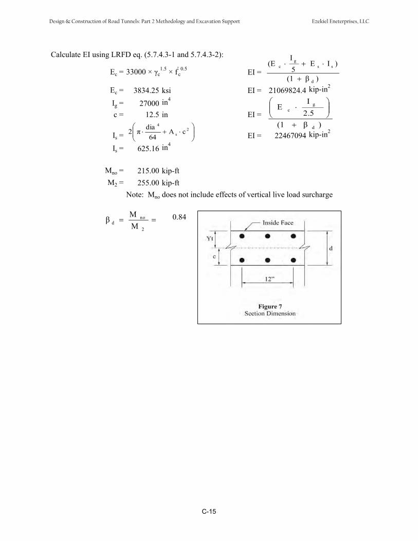
Calculate EI using LRFD eq. (5.7.4.3-1 and 5.7.4.3-2):
Ec = 33000 × c1.5 × f'
c0.5 EI =
Ec = 3834.25 ksi EI = 21069824.4 kip-in2
Ig = 27000 in4
c = 12.5 in EI =
Is = EI = 22467094 kip-in2
Is = 625.16 in4
)(1
)IE5
(E
d
ssg
c
)(12.5I
E
d
gc
2s
4
cA64
dia2
I
Mno = 215.00 kip-ftM2 = 255.00 kip-ft
Note: Mno does not include effects of vertical live load surcharge
Md
no 0.84M 2
C-15
Design & Construction of Road Tunnels: Part 2 Methodology and Excavation Support Ezekiel Eneterprises, LLC

Approximate Method (LRFD 4.5.3.2.2)
The effects of deflection on force effects on beam-columns and arches which meet the provisions of theLRFD specifications may be approximated by the Moment Magnification method described below.
For steel/concrete composite columns, the Euler buckling load, Pe, shall be determined as specified inarticle 6.9.5.1 of LRFD. For all other cases, Pe shall be taken as:
Pe = (LRFD eq. 4.5.3.2.2b-5)2u
2
)l(kEI
Where:E = modulus of elasticity (ksi)I = moment of inertia about axis under consideration (in4)k = effective length factor as specified in LRFD 4.6.2.5lu = unsupported length of a compression member (in)
Pe = 2626.67 kips
C-16
Design & Construction of Road Tunnels: Part 2 Methodology and Excavation Support Ezekiel Eneterprises, LLC

Moment Magnification (LRFD 4.5.3.2.2b)(The components for sidesway will be neglected. Bracing moment will not include lateral forceinfluence. Live load surcharge is excluded also.)The factored moments may be increased to reflect effects of deformations as follows:
LRFD eq. (4.5.3.2.2b-1):Mc = b × M2b + s × M2s Mu = 215.00 kip-ft
MuLAT = -35.08 kip-ftWhere:
LRFD eq. (4.5.3.2.2b-3)1
PP1
C
e
u
mb
Where:For members braced against sidesway and without transverse loads between supports, Cm:
MCm = 0.6 0.4 1
M 2 LRFD eq. (4.5.3.2.2b-6)Cm = 0.72
Where:M1= smaller end momentM2= larger end moment
Pu = factored axial load (kip) = 28.4 kips = resistance factor for axial compression
Pe = Euler buckling load (kip)
b = 1M2b = moment on compression member due to factored gravity loads that result in no appreciablesidesway calculated by conventional first-order elastic frame analysis; always positive (kip-ft)M2b = 179.92 kip-ft
Mc = 179.92 kip-ft
C-17
Design & Construction of Road Tunnels: Part 2 Methodology and Excavation Support Ezekiel Eneterprises, LLC

Factored flexural resistance (LRFD 5.7.3.2.1)The factored resistance Mr shall be taken as:Mr = Mn
Where: = resistance factor = 0.9
Mn = nominal resistance (kip-in) The nominal flexural resistance may be taken as:
(LRFD eq. 5.7.3.2.2-1)2ad'f'A'
2adfAM syssysn
Do not consider compression steel for calculating Mn.
Where: As = area of nonprestressed tension reinforcement (in2) fy = specified yield strength of reinforcing bars (ksi) ds = distance from extreme compression fiber to centroid of nonprestressed tensile reinforcement (in2) a = depth of equivalent stress block (in) = 1 × c
Where:1 = stress block factor specified in Section 5.7.2.2 of LRFD
c = distance from the extreme compression fiber to the neutral axis
c = LRFD eq. (5.7.3.1.2-4)ys
bf'0.85 1c
Where:As= 2.0 in2
fy= 60.0 ksif'c= 4.0 ksi
1= 0.85b= 12.0 in
c = 3.46 in a = 2.94 inMn = 3153.53 kip-in = 262.79 kip-ft
Mn = 236.51 kip-ft OK ( Mc)Mr = 236.51 kip-ft Mr > Mu
C-18
fA
Design & Construction of Road Tunnels: Part 2 Methodology and Excavation Support Ezekiel Eneterprises, LLC
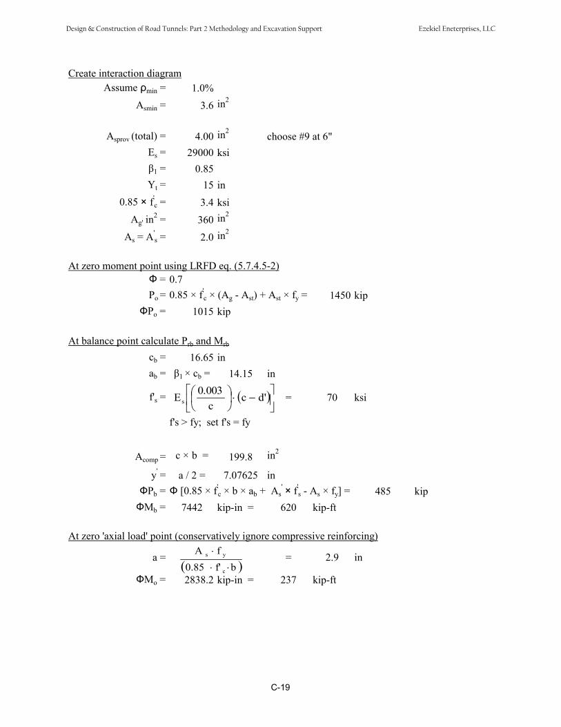
Create interaction diagramAssume min = 1.0%
Asmin = 3.6 in2
A 2sprov (total) = 4.00 in choose #9 at 6"
Es = 29000 ksi
1 = 0.85Yt = 15 in
0.85 × f'c = 3.4 ksi
A 2 2g' in = 360 in
As = A's = 2.0 in2
At zero moment point using LRFD eq. (5.7.4.5-2) = 0.7
Po = 0.85 × f'c × (Ag - Ast) + Ast × fy = 1450 kip
Po = 1015 kip
At balance point calculate Prb and Mrb
cb = 16.65 in ab = 1 × cb = 14.15 in
f's = = 70 ksid'cc
0.003Es
f's > fy; set f's = fy
Acomp = c × b = 199.8 in2
y' = a / 2 = 7.07625 inPb = [0.85 × f'
c × b × ab + A 's × f'
s - As × fy] = 485 kipMb = 7442 kip-in = 620 kip-ft
At zero 'axial load' point (conservatively ignore compressive reinforcing)
a = = 2.9 inbf'0.85
fA
c
ys
Mo = 2838.2 kip-in = 237 kip-ft
C-19
Design & Construction of Road Tunnels: Part 2 Methodology and Excavation Support Ezekiel Eneterprises, LLC

At intermediate points
a, in c = a/b1 Acomp, in2 f's,ksi fs,ksi fy, ksi Mn, k-ft Pn,
kips237 0
2.9 3.4 34.8 36 657 60 292 303 3.5 36 38 635 60 298 364 4.7 48 50 476 60 355 905 5.9 60 57 381 60 401 1336 7.1 72 62 317 60 435 1677 8.2 84 66 272 60 461 1958 9.4 96 69 238 60 484 224
10 11.8 120 72 190 60 521 28112 14.1 144 75 159 60 546 33815 17.6 180 77 127 60 561 42418 21.2 216 79 106 60 548 50919 22.4 228 79 100 60 537 53821 24.7 252 80 91 60 507 59523 27.1 276 81 83 60 465 65225 29.4 300 81 76 60 410 709
0 1015End 1 77 28End 2 255 28
Note may decrease from 0.90 to 0.75 as a increases from 0.0 to ab. Use 0.75 to be conservative.
Where:Acomp = a × 12 in2
0.003f's = Es c A' ksic s
0.003fs = Es c A ksisca
Acomp A's yt 0.85 f' A f d y A' f' y d'Mn = 2 c s y t s s t k-ft
12Pn = (Acomp - A s) ×0.85 × fc + As × f s - As × fy kips
C-20
' ' ' '
Design & Construction of Road Tunnels: Part 2 Methodology and Excavation Support Ezekiel Eneterprises, LLC
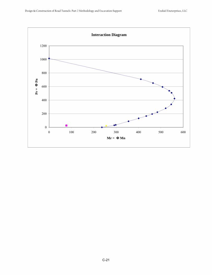
Interaction Diagram
0
200
400
600
800
1000
1200
0 100 200 300 400 500 600
Mr = Mn
Pr =
Pn
C-21
Design & Construction of Road Tunnels: Part 2 Methodology and Excavation Support Ezekiel Eneterprises, LLC
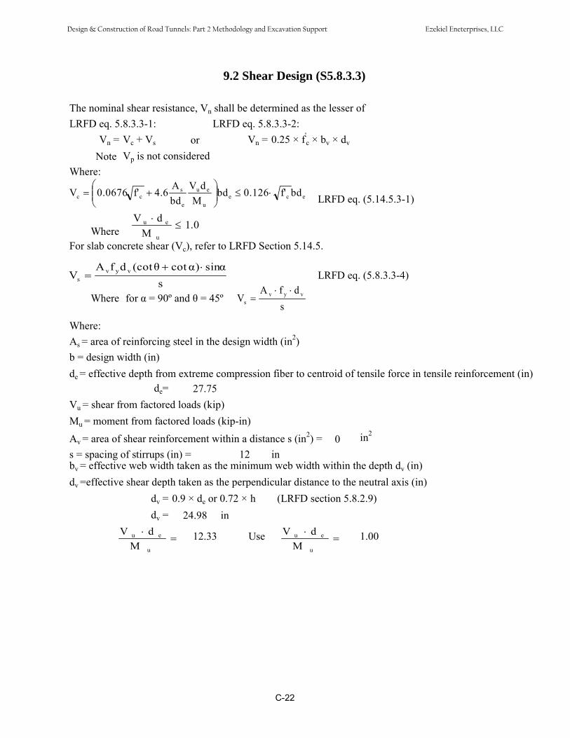
9.2 Shear Design (S5.8.3.3)
The nominal shear resistance, Vn shall be determined as the lesser ofLRFD eq. 5.8.3.3-1: LRFD eq. 5.8.3.3-2:
Vn = Vc + Vs or Vn = 0.25 × f'c × bv × dv
Note Vp is not consideredWhere:
LRFD eq. (5.14.5.3-1)eceu
eu
e
scc bdf'0.126bd
MdV
bdA
4.6f'0.0676V
Where 1.0dV eu
M uFor slab concrete shear (Vc), refer to LRFD Section 5.14.5.
LRFD eq. (5.8.3.3-4)sin)cot(cotdfA
V vyvs
Where for = 90º and = 45ºs
dfAV vyv
s
s
Where:As = area of reinforcing steel in the design width (in2)b = design width (in)de = effective depth from extreme compression fiber to centroid of tensile force in tensile reinforcement (in)
de= 27.75Vu = shear from factored loads (kip)Mu = moment from factored loads (kip-in)
Av = area of shear reinforcement within a distance s (in2) = 0 in2
s = spacing of stirrups (in) = 12 inbv = effective web width taken as the minimum web width within the depth dv (in)dv =effective shear depth taken as the perpendicular distance to the neutral axis (in)
dv = 0.9 × de or 0.72 × h (LRFD section 5.8.2.9)dv = 24.98 in
12.33 Use 1.00u
eu
MdV
u
eu
MdV
C-22
Design & Construction of Road Tunnels: Part 2 Methodology and Excavation Support Ezekiel Eneterprises, LLC

Maximum shear and associated moment from analysis output:Vu = 28 kip Mu = 63.0 kip-ft
Vc = 63.42 kip value controlsor Vc = 83.92 kip
Vs = 0.00 kip
Vn = 63.42 kipVn = 299.70 kip therefore Vn = 63.42 kip
= 0.90Vn = 57.08 kip > Vu OK
C-23
Design & Construction of Road Tunnels: Part 2 Methodology and Excavation Support Ezekiel Eneterprises, LLC

10. Bottom Slab Design
10.1 Slenderness Check (S5.7.4.3)
K = 0.65 1 = 0.85lu = 37.25 ft = 447 in ds = 18.75 ind = 1.75 ft = 21.0 in d's = 3.25 in
I = 9261 in4 #8 bar dia. = 1.00 inr = 6.06 in
k × (lu / r) = 47.93From analysis output
where M1 = 13 kip-ft P1 = 23.6 kipM2 = 57.1 kip-ft P2 = 23.6 kip
M34 12 1 = 31.27M 2
Consider slenderness since k × (lu / r) Mis greater than 34 12 1
M 2
Calculate EI:Ec = 3834.25 ksiI = 9261 in4g
c = 8 in EI = 3427836.25 kip-in2
I 4s = 202.34 in EI = 6855672.51 kip-in2
Mno = 61.20 kip-ftM2 = 57.10 kip-ft
Note: Mno does not include effects of vertical live load surcharge
M 1.07nod M 2
C-24
Design & Construction of Road Tunnels: Part 2 Methodology and Excavation Support Ezekiel Eneterprises, LLC
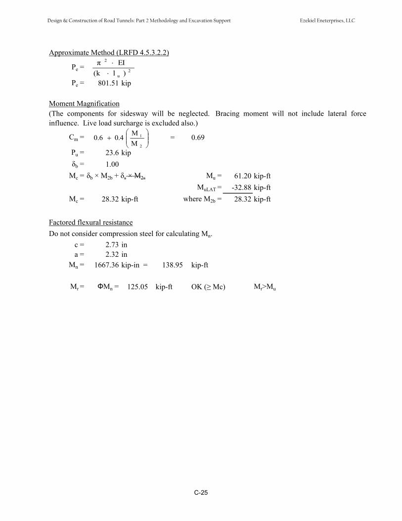
Approximate Method (LRFD 4.5.3.2.2)
Pe =
Pe = 801.51 kip
2u
2
)l(kEI
Moment Magnification(The components for sidesway will be neglected. Bracing moment will not include lateral forceinfluence. Live load surcharge is excluded also.)
MCm 0.6 0.4 1 = = 0.69M 2
Pu = 23.6 kip
b = 1.00Mc = b × M2b + s × M2s Mu = 61.20 kip-ft
MuLAT = -32.88 kip-ftMc = 28.32 kip-ft where M2b = 28.32 kip-ft
Factored flexural resistanceDo not consider compression steel for calculating Mn.
c = 2.73 in a = 2.32 in
Mn = 1667.36 kip-in = 138.95 kip-ft
Mr = Mn = 125.05 kip-ft OK ( Mc) Mr>Mu
C-25
Design & Construction of Road Tunnels: Part 2 Methodology and Excavation Support Ezekiel Eneterprises, LLC

Create interaction diagramAssume min = 1.0%
Asmin = 2.52 in2
Asprov (total) = 3.16 in2 choose #8 at 6"Es = 29000 ksi
1 = 0.85Yt = 10.5 in
0.85 × f'c = 3.4 ksi
Ag' in2 = 252 in2
As = A' 2s = 1.6 in
At zero moment pointPo = 1036 kipPo = 725 kip
At balance point calculate Prb and Mrb
cb = 11.25 inab = 9.56 inf's = 62 ksi
f's > fy; set f's = fy
Acomp = 114.75 in2
y' = 4.78125 inPb = 271 kip
Mb = 3303 kip-in = 275 kip-ft
At zero 'axial load' point (conservatively ignore compressive reinforcing)a = 2.3 in
Mo = 1500.6 kip-in = 125 kip-ft
C-26
Design & Construction of Road Tunnels: Part 2 Methodology and Excavation Support Ezekiel Eneterprises, LLC
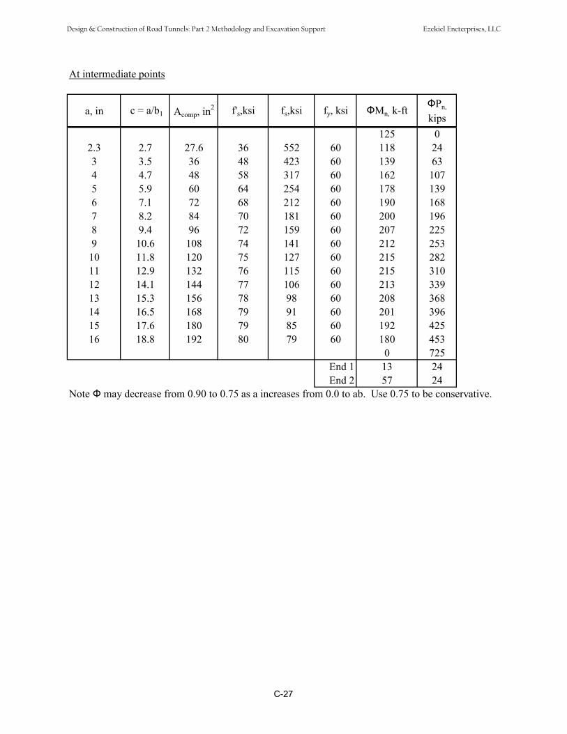
At intermediate points
a, in c = a/b1 Acomp, in2 f's,ksi fs,ksi fy, ksi Mn, k-ft Pn,
kips125 0
2.3 2.7 27.6 36 552 60 118 243 3.5 36 48 423 60 139 634 4.7 48 58 317 60 162 1075 5.9 60 64 254 60 178 1396 7.1 72 68 212 60 190 1687 8.2 84 70 181 60 200 1968 9.4 96 72 159 60 207 2259 10.6 108 74 141 60 212 253
10 11.8 120 75 127 60 215 28211 12.9 132 76 115 60 215 31012 14.1 144 77 106 60 213 33913 15.3 156 78 98 60 208 36814 16.5 168 79 91 60 201 39615 17.6 180 79 85 60 192 42516 18.8 192 80 79 60 180 453
0 725End 1 13 24End 2 57 24
Note may decrease from 0.90 to 0.75 as a increases from 0.0 to ab. Use 0.75 to be conservative.
C-27
Design & Construction of Road Tunnels: Part 2 Methodology and Excavation Support Ezekiel Eneterprises, LLC

Interaction Diagram
0
100
200
300
400
500
600
700
800
0 50 100 150 200 250
Mr = Mn
Pr =
Pn
C-28
Design & Construction of Road Tunnels: Part 2 Methodology and Excavation Support Ezekiel Eneterprises, LLC
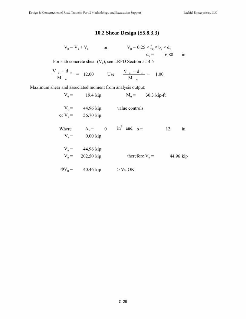
10.2 Shear Design (S5.8.3.3)
Vn = Vc + Vs or Vn = 0.25 × f'c × bv × dv
dv = 16.88 inFor slab concrete shear (Vc), see LRFD Section 5.14.5
12.00 Use 1.00u
eu
MdV
u
eu
MdV
Maximum shear and associated moment from analysis output:
Vu = 19.4 kip Mu = 30.3 kip-ft
Vc = 44.96 kip value controlsor Vc = 56.70 kip
Where A = 0 in2v and s = 12 in
Vs = 0.00 kip
Vn = 44.96 kipVn = 202.50 kip therefore Vn = 44.96 kip
Vn = 40.46 kip > Vu OK
C-29
Design & Construction of Road Tunnels: Part 2 Methodology and Excavation Support Ezekiel Eneterprises, LLC
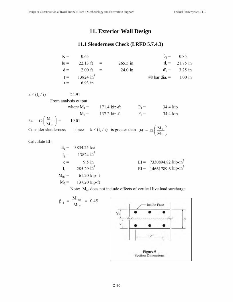
11. Exterior Wall Design
11.1 Slenderness Check (LRFD 5.7.4.3)
K = 0.65 1 = 0.85lu = 22.13 ft = 265.5 in ds = 21.75 ind = 2.00 ft = 24.0 in d's = 3.25 in
I = 13824 in4 #8 bar dia. = 1.00 inr = 6.93 in
k × (lu / r) = 24.91From analysis output
where M1 = 171.4 kip-ft P1 = 34.4 kipM2 = 137.2 kip-ft P2 = 34.4 kip
M34 12 1 = 19.01M 2
Consider slenderness since k × (lu / r) is greater than M34 12 1
M 2
Calculate EI:Ec = 3834.25 ksiI = 13824 in4g
c = 9.5 in EI = 7330894.82 kip-in2
I 4s = 285.29 in EI = 14661789.6 kip-in2
Mno = 61.20 kip-ftM2 = 137.20 kip-ft
Note: Mno does not include effects of vertical live load surcharge
M nod 0.45
M 2
C-30
Design & Construction of Road Tunnels: Part 2 Methodology and Excavation Support Ezekiel Eneterprises, LLC
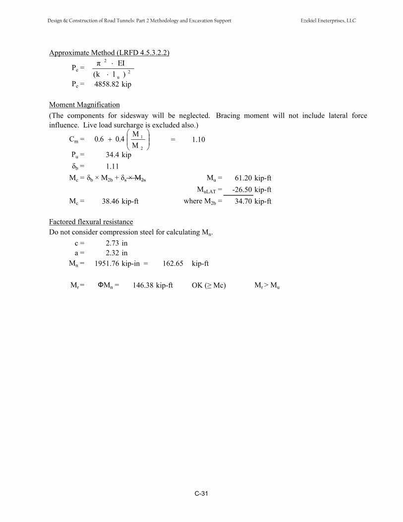
Approximate Method (LRFD 4.5.3.2.2)
Pe =
Pe = 4858.82 kip
2u
2
)l(kEI
Moment Magnification(The components for sidesway will be neglected. Bracing moment will not include lateral forceinfluence. Live load surcharge is excluded also.)
MCm = 0.6 0.4 1 = 1.10
M 2Pu = 34.4 kip
b = 1.11Mc = b × M2b + s × M2s Mu = 61.20 kip-ft
MuLAT = -26.50 kip-ftMc = 38.46 kip-ft where M2b = 34.70 kip-ft
Factored flexural resistanceDo not consider compression steel for calculating Mn.
c = 2.73 ina = 2.32 in
Mn = 1951.76 kip-in = 162.65 kip-ft
Mr = Mn = 146.38 kip-ft OK ( Mc) Mr > Mu
C-31
Design & Construction of Road Tunnels: Part 2 Methodology and Excavation Support Ezekiel Eneterprises, LLC

Create interaction diagramAssume min = 1.0%
Asmin = 2.88 in2
Asprov (total) = 3.16 in2 choose #8 at 6"Es = 29000 ksi
1 = 0.85Yt = 12 in
0.85 × f'c = 3.4 ksi
Ag' in2 = 288 in2
As = A' 2s = 1.6 in
At zero moment pointPo = 1158 kipPo = 811 kip
At balance point calculate Prb and Mrb
cb = 13.05 inab = 11.09 inf's = 65 ksi
f's > fy; set f's = fy
Acomp = 133.11 in2
y' = 5.54625 inPb = 313 kip
Mb = 4176 kip-in = 348 kip-ft
At zero 'axial load' point (conservatively ignore compressive reinforcing)a = 2.3 in
Mo = 1756.6 kip-in = 146 kip-ft
C-32
Design & Construction of Road Tunnels: Part 2 Methodology and Excavation Support Ezekiel Eneterprises, LLC
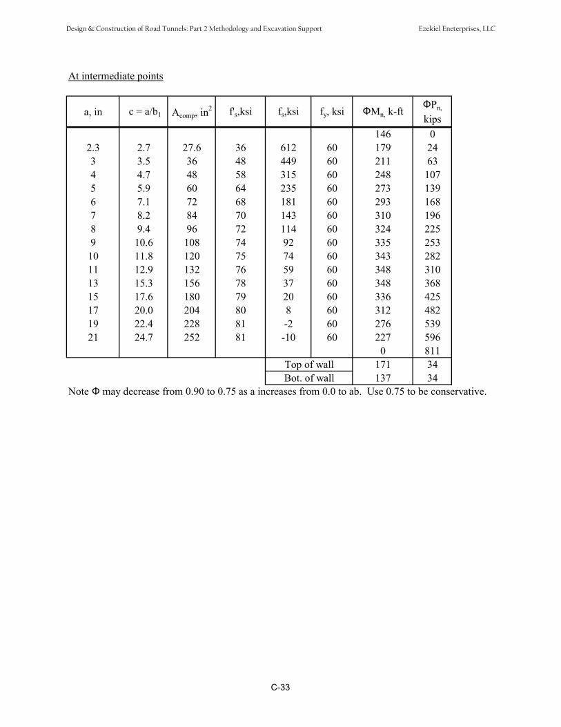
At intermediate points
a, in c = a/b1 Acomp, in2 f's,ksi fs,ksi fy, ksi Mn, k-ft Pn,
kips146 0
2.3 2.7 27.6 36 612 60 179 243 3.5 36 48 449 60 211 634 4.7 48 58 315 60 248 1075 5.9 60 64 235 60 273 1396 7.1 72 68 181 60 293 1687 8.2 84 70 143 60 310 1968 9.4 96 72 114 60 324 2259 10.6 108 74 92 60 335 253
10 11.8 120 75 74 60 343 28211 12.9 132 76 59 60 348 31013 15.3 156 78 37 60 348 36815 17.6 180 79 20 60 336 42517 20.0 204 80 8 60 312 48219 22.4 228 81 -2 60 276 53921 24.7 252 81 -10 60 227 596
0 811171 34137 34Bot. of wall
Top of wall
Note may decrease from 0.90 to 0.75 as a increases from 0.0 to ab. Use 0.75 to be conservative.
C-33
Design & Construction of Road Tunnels: Part 2 Methodology and Excavation Support Ezekiel Eneterprises, LLC

Interaction Diagram
0
100
200
300
400
500
600
700
800
900
0 50 100 150 200 250 300 350 400
Mr = Mn
Pr =
Pn
C-34
Design & Construction of Road Tunnels: Part 2 Methodology and Excavation Support Ezekiel Eneterprises, LLC

11.2 Shear Design (S5.8.3.3)
Maximum shear from analysis output:Vu = 20.76 kip
Where = 2bv = 12 in
dv = 19.58 inVc = 0.0316 × × f' 0.5
c × bv × dv LRFD eq. (5.8.3.3-3)Vc = 29.69 kip
Where Av = 0 in2 and s = 12 inVs = 0.00 kip
Vn = 29.69 kipVn = 234.90 kip therefore Vn = 29.69 kip
Vn = 26.72 kip > Vu OK
C-35
Design & Construction of Road Tunnels: Part 2 Methodology and Excavation Support Ezekiel Eneterprises, LLC
Appendix D
Tunnel Boring Machines
Design & Construction of Road Tunnels: Part 2 Methodology and Excavation Support Ezekiel Eneterprises, LLC
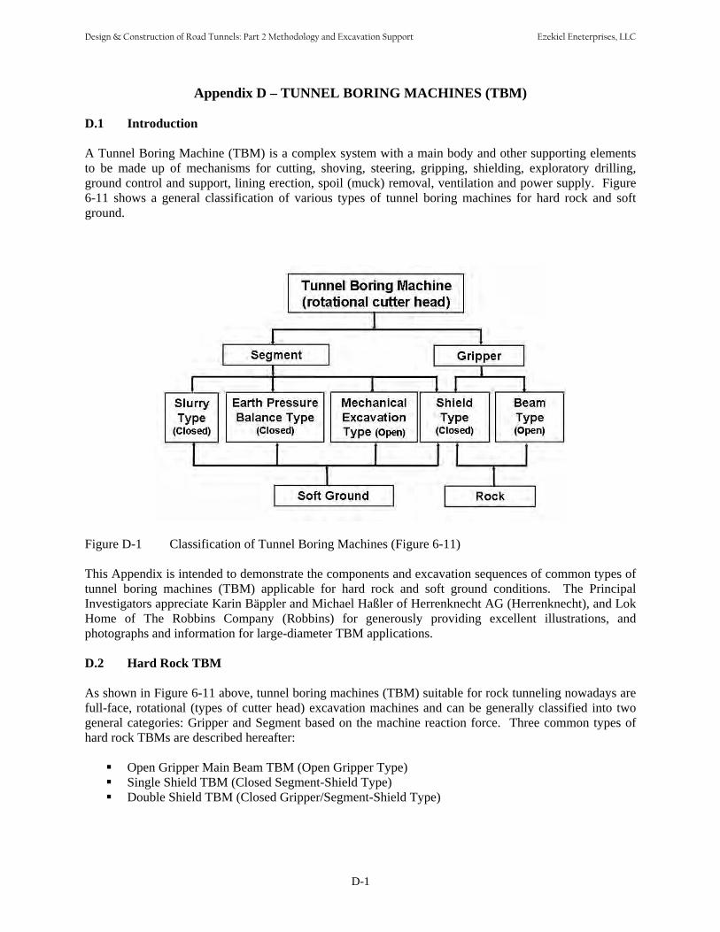
Appendix D – TUNNEL BORING MACHINES (TBM)
D.1 Introduction
A Tunnel Boring Machine (TBM) is a complex system with a main body and other supporting elements to be made up of mechanisms for cutting, shoving, steering, gripping, shielding, exploratory drilling, ground control and support, lining erection, spoil (muck) removal, ventilation and power supply. Figure 6-11 shows a general classification of various types of tunnel boring machines for hard rock and softground.
Figure D-1 Classification of Tunnel Boring Machines (Figure 6-11)
This Appendix is intended to demonstrate the components and excavation sequences of common types of tunnel boring machines (TBM) applicable for hard rock and soft ground conditions. The Principal Investigators appreciate Karin Bäppler and Michael Haßler of Herrenknecht AG (Herrenknecht), and Lok Home of The Robbins Company (Robbins) for generously providing excellent illustrations, and photographs and information for large-diameter TBM applications.
D.2 Hard Rock TBM
As shown in Figure 6-11 above, tunnel boring machines (TBM) suitable for rock tunneling nowadays are full-face, rotational (types of cutter head) excavation machines and can be generally classified into two general categories: Gripper and Segment based on the machine reaction force. Three common types of hard rock TBMs are described hereafter:
Open Gripper Main Beam TBM (Open Gripper Type)Single Shield TBM (Closed Segment-Shield Type)Double Shield TBM (Closed Gripper/Segment-Shield Type)
D-1
Design & Construction of Road Tunnels: Part 2 Methodology and Excavation Support Ezekiel Eneterprises, LLC

D.2.1 Open Gripper Main Beam TBM
The open gripper-beam category of TBMs is suited for stable to friable rock with occasional fractured zones and controllable groundwater inflows. Figure D-2 (Robbins) illustrates a typical diagram of a modern open gripper main beam TBM and highlights the major components including:
• Cutterhead (with disc cutters) and Front Support• Main Beam• Thrust (propel) Cylinder• Gripper• Rear Support• Conveyor• Trailing backup system for muck and material transportation, ventilation, power supply, etc.
(a)
(b)
Figure D-2 Typical Diagram for an Open Gripper Main Beam TBM (Robbins).
D-2
Design & Construction of Road Tunnels: Part 2 Methodology and Excavation Support Ezekiel Eneterprises, LLC

The front of the gripper TBM is a rotating cutterhead that matches the diameter of the tunnel (Figure D-3). The cutterhead holds disc cutters. As the cutterhead turns, hydraulic propel cylinders push the cutters into the rock. The transfer of this high thrust through the rolling disc cutters creates fractures in the rock causing chips to break away from the tunnel face (Figure 6-9). A floating gripper system pushes on the sidewalls and is locked in place while the propel cylinders extend, allowing the main beam to advance the TBM. The machine can be continuously steered while gripper shoes push on the sidewalls to react the machine's forward thrust. Buckets in the rotating cutterhead scoop up and deposit the muck on to a belt conveyor inside the main beam. The muck is then transferred to the rear of the machine for removal from the tunnel. At the end of a stroke the rear legs of the machine are lowered, the grippers and propel cylinders are retracted. The retraction of the propel cylinders repositions the gripper assembly for the next boring cycle. The grippers are extended, the rear legs lifted, and boring begins again.
Figure D-3 Herrenknecht S-210 Gripper TBM (Herrenknecht)
Figure D-3 shows the front of the Herrenknecht S-210 Gripper TBM used in the construction for the Gotthard Base Tunnel, Switzerland. See Table D-1 for more data about the machine (Herrenknecht). Although uncommon, hard rock gripper TBMs with a diameter over 46’ (145m) have been made, and this limit is constantly being challenged and extended for new mega projects.
D-3
Design & Construction of Road Tunnels: Part 2 Methodology and Excavation Support Ezekiel Eneterprises, LLC
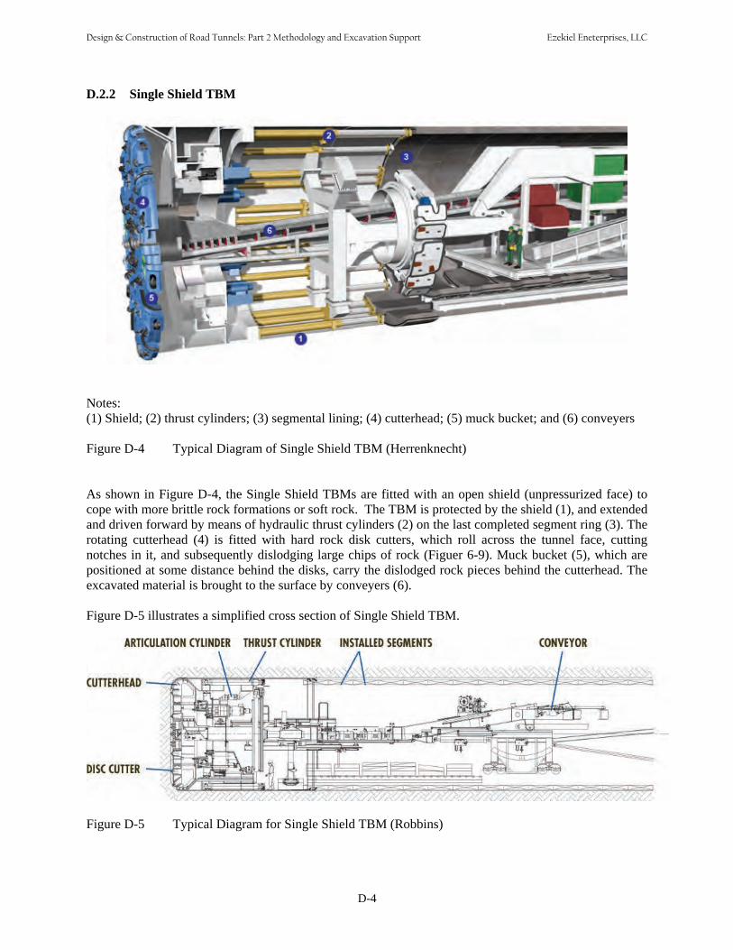
D.2.2 Single Shield TBM
Notes: (1) Shield; (2) thrust cylinders; (3) segmental lining; (4) cutterhead; (5) muck bucket; and (6) conveyers
Figure D-4 Typical Diagram of Single Shield TBM (Herrenknecht)
As shown in Figure D-4, the Single Shield TBMs are fitted with an open shield (unpressurized face) to cope with more brittle rock formations or soft rock. The TBM is protected by the shield (1), and extended and driven forward by means of hydraulic thrust cylinders (2) on the last completed segment ring (3). The rotating cutterhead (4) is fitted with hard rock disk cutters, which roll across the tunnel face, cutting notches in it, and subsequently dislodging large chips of rock (Figuer 6-9). Muck bucket (5), which are positioned at some distance behind the disks, carry the dislodged rock pieces behind the cutterhead. The excavated material is brought to the surface by conveyers (6).
Figure D-5 illustrates a simplified cross section of Single Shield TBM.
Figure D-5 Typical Diagram for Single Shield TBM (Robbins)
D-4
Design & Construction of Road Tunnels: Part 2 Methodology and Excavation Support Ezekiel Eneterprises, LLC
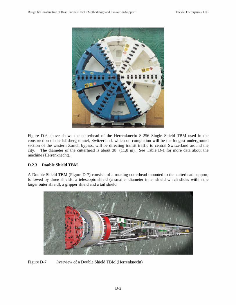
Figure D-6 above shows the cutterhead of the Herrenknecht S-256 Single Shield TBM used in the construction of the Islisberg tunnel, Switzerland, which on completion will be the longest underground section of the western Zurich bypass, will be directing transit traffic to central Switzerland around the city. The diameter of the cutterhead is about 38’ (11.8 m). See Table D-1 for more data about the machine (Herrenknecht).
D.2.3 Double Shield TBM
A Double Shield TBM (Figure D-7) consists of a rotating cutterhead mounted to the cutterhead support, followed by three shields: a telescopic shield (a smaller diameter inner shield which slides within the larger outer shield), a gripper shield and a tail shield.
Figure D-7 Overview of a Double Shield TBM (Herrenknecht)
D-5
Design & Construction of Road Tunnels: Part 2 Methodology and Excavation Support Ezekiel Eneterprises, LLC
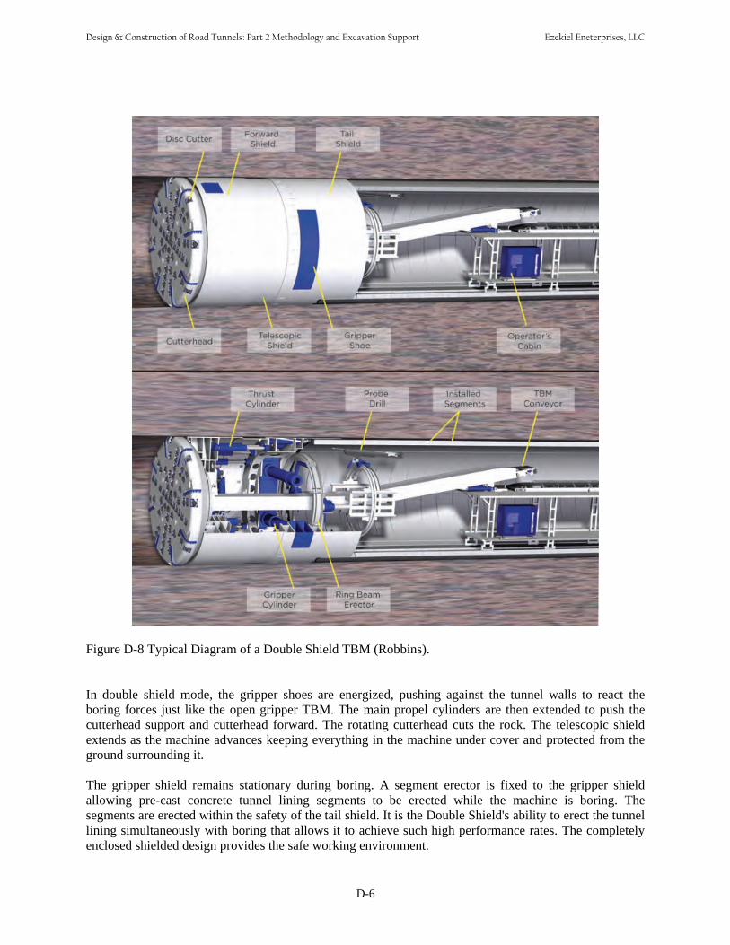
Figure D-8 Typical Diagram of a Double Shield TBM (Robbins).
In double shield mode, the gripper shoes are energized, pushing against the tunnel walls to react the boring forces just like the open gripper TBM. The main propel cylinders are then extended to push the cutterhead support and cutterhead forward. The rotating cutterhead cuts the rock. The telescopic shield extends as the machine advances keeping everything in the machine under cover and protected from the ground surrounding it.
The gripper shield remains stationary during boring. A segment erector is fixed to the gripper shield allowing pre-cast concrete tunnel lining segments to be erected while the machine is boring. The segments are erected within the safety of the tail shield. It is the Double Shield's ability to erect the tunnel lining simultaneously with boring that allows it to achieve such high performance rates. The completely enclosed shielded design provides the safe working environment.
D-6
Design & Construction of Road Tunnels: Part 2 Methodology and Excavation Support Ezekiel Eneterprises, LLC

If the ground becomes too weak to support the gripper shoe pressure, the machine thrust must be reacted another way. In this situation, the machine can be operated in "single shield mode". Auxiliary thrust cylinders are located in the gripper shield. In single shield mode they transfer the thrust from the gripper shield to the tunnel lining. Since the thrust is transferred to the tunnel lining, it is not possible to erect the lining simultaneously with boring. In the single shield mode, tunnel boring and tunnel lining erection are sequential operations.
Figure D-9 above shows the cutterhead (about 40’ diameter) of the Herrenknecht S-376 Double Shield TBM which is being used for the construction of Brisbane North-South Bypass Tunnel See Table D-1 for more data about the machine (Herrenknecht).
D.3 Pressurized Face Soft Ground TBM
As shown in Figure 6-11 above, various types of tunnel boring machines (TBM) are suitable for soft ground tunneling in different conditions. Chapter 7 presents briefly the history and development of shield tunneling machines. Table 7-4 (reproduced below) lists various types of shield tunneling methods in soft ground.
Nowadays modern pressurized-face closed shield TBMs are predominantly utilized in large diameter soft ground tunneling. Section 7.3 describes the principles of the two common types: earth pressure balance (EPB) machines and slurry face machines (SFM) , and offers guidelines for selecting between EPB and SFM. This appendix presents the components of each type of TBM and describes the construction sequences.
D-7
Design & Construction of Road Tunnels: Part 2 Methodology and Excavation Support Ezekiel Eneterprises, LLC
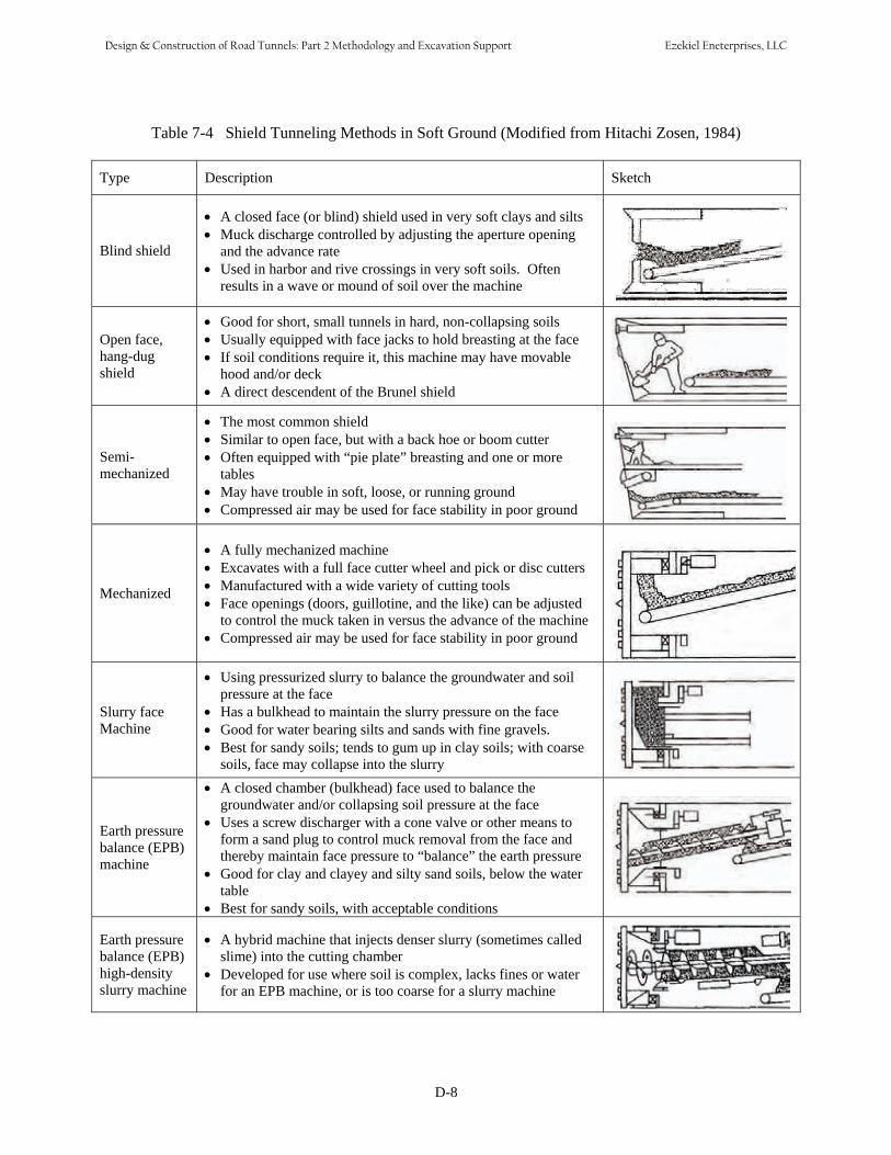
Table 7-4 Shield Tunneling Methods in Soft Ground (Modified from Hitachi Zosen, 1984)
Type Description Sketch
Blind shield
• A closed face (or blind) shield used in very soft clays and silts• Muck discharge controlled by adjusting the aperture opening
and the advance rate• Used in harbor and rive crossings in very soft soils. Often
results in a wave or mound of soil over the machine
Open face, hang-dug shield
• Good for short, small tunnels in hard, non-collapsing soils• Usually equipped with face jacks to hold breasting at the face• If soil conditions require it, this machine may have movable
hood and/or deck• A direct descendent of the Brunel shield
Semi-mechanized
• The most common shield• Similar to open face, but with a back hoe or boom cutter• Often equipped with “pie plate” breasting and one or more
tables• May have trouble in soft, loose, or running ground• Compressed air may be used for face stability in poor ground
Mechanized
• A fully mechanized machine• Excavates with a full face cutter wheel and pick or disc cutters• Manufactured with a wide variety of cutting tools• Face openings (doors, guillotine, and the like) can be adjusted
to control the muck taken in versus the advance of the machine• Compressed air may be used for face stability in poor ground
Slurry face Machine
• Using pressurized slurry to balance the groundwater and soilpressure at the face
• Has a bulkhead to maintain the slurry pressure on the face• Good for water bearing silts and sands with fine gravels.• Best for sandy soils; tends to gum up in clay soils; with coarse
soils, face may collapse into the slurry
Earth pressure balance (EPB) machine
• A closed chamber (bulkhead) face used to balance thegroundwater and/or collapsing soil pressure at the face
• Uses a screw discharger with a cone valve or other means toform a sand plug to control muck removal from the face and thereby maintain face pressure to “balance” the earth pressure
• Good for clay and clayey and silty sand soils, below the watertable
• Best for sandy soils, with acceptable conditions
Earth pressure balance (EPB) high-density slurry machine
• A hybrid machine that injects denser slurry (sometimes calledslime) into the cutting chamber
• Developed for use where soil is complex, lacks fines or waterfor an EPB machine, or is too coarse for a slurry machine
D-8
Design & Construction of Road Tunnels: Part 2 Methodology and Excavation Support Ezekiel Eneterprises, LLC

D.3.1 Earth Pressure Balance Machine
As discussed in Section 7.3, earth pressure balance machines (EPB) (Figure D-10) are pressurized face shield machines specially designed for operation in soft ground especially where the ground is silty and has a high percentage of fines both of which will assist the formation of a plug in the screw conveyor and will control groundwater inflows.
Notes: (1) Cutterhead; (2) excavation chamber; (3) bulkhead; (4) thrust cylinders; (5) screw conveyor; (6)segment erector; and (7) Segmental Lining
Figure D-10 Overview of Earth Pressure Balance Machine (EPB)
D-9
Design & Construction of Road Tunnels: Part 2 Methodology and Excavation Support Ezekiel Eneterprises, LLC

The EPB machine continuously supports to the tunnel face by balancing the inside earth and water pressure against the thrust pressure of the machine. The working area inside the EPB machine is completely sealed against the fluid pressure of the ground outside the machine.
As shown in Figure D-10, the soil is excavated (loosened) by the cutterhead (1) serves to support the tunnel face. The area of the shield in which the cutterhead rotates is known as an excavation chamber (2) and is separated from the section of the shield under atmospheric pressure by the pressure bulkhead (3). The excavated soil falls through the openings of the cutterhead into the excavation chamber and mixes with the plastic soil already there. Uncontrolled penetration of the soil from the tunnel face into the excavation chamber is prevented because the force of the thrust cylinders (4) is transmitted from the pressure bulkhead onto the soil. A state of equilibrium is reached when the soil in the excavation chamber cannot be compacted any further by the native earth and water pressure.
The excavated material is removed from the excavation chamber by a screw conveyor (5). The amount of material removed is controlled by the speed of the screw and the cross-section of the opening of the upper screw conveyor driver. The pressure in the excavation chamber is controlled by balancing the rate of advance of the machine and the rate of extraction of the excavated material by the screw conveyor. The screw conveyor conveys the excavated material to the first of a series of conveyor belts. The excavated material is conveyed on these belts to the so-called reversible conveyor from which the transportation gantries in the backup areas are loaded when the conveyor belt is put into reverse.
The tunnels are normally lined with reinforced precast lining segments (7), which are positioned under atmospheric pressure conditions by means of erectors (6) in the area of the shield behind the pressure bulkhead and then temporarily bolted in place. Grout is continuously injected into the remaining gap between the segments' outer side and the surrounding medium injection openings in the tailskin or openings directly in the segments.
Manual or automatic operation of the EPB system is possible through the integrated PLC and computer-control systems.
As discussed above, the EPB machines support the tunnel face with pressure from the excavated (and remolded) soil within the excavation chamber and crew conveyor. Therefore, EPB machines perform more effectively when the soil immediately ahead of the cutterhead and in the excavation chamber forms a plastic plug, which prevents water inflow and ensures face support. This is accomplished by conditioning the soils ahead of the cutterhead with foams and.or polymers. O’Carroll 2005 lists the benefits of soil conditioning for the EPB machine operation including:
Improved ground controlTorque and power requirement reductionAbrasion reductionAdhesion (stickiness) reduction, andPermeability reduction.
Figure D-11 shows the front of the Herrenknecht S-300 EPB TBM used in the construction of the M30-By-Pass Sur Tunel Norte project in Madrid, Spain. The diameter of the cutterhead is almost 50’ (15.2 m). See Table D-1 for more data about the machine (Herrenknecht).
D-10
Design & Construction of Road Tunnels: Part 2 Methodology and Excavation Support Ezekiel Eneterprises, LLC

Figure D-11 The EPB Machine for the M30-By-Pass Sur Tunel Norte project in Madrid.
D.3.2 Slurry Face Machine
As discussed in Section 7.3, slurry face machine (SFM) are pressurized face shield machines specially designed for tunneling in soft ground especially where the ground is loose waterbearing granular soils that are easily separated from the slurry at the separation plant. The SFM provides stability at the face hydraulically by bentonite slurry kept under pressure to counteract the native earth and groundwater pressure, and to prevent an uncontrolled penetration of soil or a loss of stability at the tunnel face.
Figure D-12 shows typical diagrams of Herrenknecht’s mixshield machine which employs the slurry face support principle. At the mixshield machine face the soil is loosened by the cutterhead (1) rotating in the bentonite suspension. The soil then mixes with the bentonite suspension. The area of the shield in which the cutterhead rotates is known as the excavation chamber (2) and is separated by the pressure bulkhead (3) from the section of the shield under atmospheric pressure.
The bentonite suspension supplied by the feed line (4) is applied in the excavation chamber via an air cushion (5) at a pressure equaling the native soil and water pressure, thus preventing an uncontrolled penetration of the soil or a loss of stability at the tunnel face. For this reason the excavation chamber behind the cutting wheel is separated from the pressure bulkhead by a so-called submerged wall (6). The area of the submerged wall and pressure bulkhead is known as the pressure/working chamber. Note that unlike the typical slurry shield machines, in the mixshield machines. the support pressure in the excavation chamber is not directly controlled by suspension pressure but by a compressible air cushion between the pressure bulkhead and the submerged wall.
D-11
Design & Construction of Road Tunnels: Part 2 Methodology and Excavation Support Ezekiel Eneterprises, LLC

The loosened soil mixed with the suspension is pumped through the feeding circuit to the separation plant outside the tunnel. In order to prevent blockages to the feeding circuit and to ensure trouble-free operation of the discharge pumps, a sieve of largish stones and clumps of soil is placed in front of the suction pipe to block the access to the suction channel.
Notes: (1) Cutterhead; (2) excavation chamber; (3) bulkhead; (4) slurry feed line; (5) air cushion; (6) wall; (7)Segmental Lining; and (8) segment erector
Figure D-12 Overview of Slurry Face Machine (SFM) (Herrenknecht’s Mixshield Machines)
D-12
Design & Construction of Road Tunnels: Part 2 Methodology and Excavation Support Ezekiel Eneterprises, LLC

Figure D-13 shows the Herrenknecht S-317 Mixshield TBM used in the construction of the Shanghai Changjiang Under River Tunnel Project in China. The diameter of the cutterhead is over 50’ (15.4 m). See Table D-1 for more data about the machine (Herrenknecht).
Figure D-13 Photograph of Herrenknecht S-317 Mixshield TBM
D-13
Design & Construction of Road Tunnels: Part 2 Methodology and Excavation Support Ezekiel Eneterprises, LLC
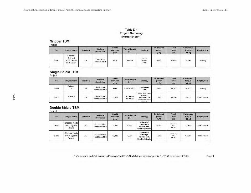
D-14
Design & Construction of Road Tunnels: Part 2 Methodology and Excavation Support Ezekiel Eneterprises, LLC
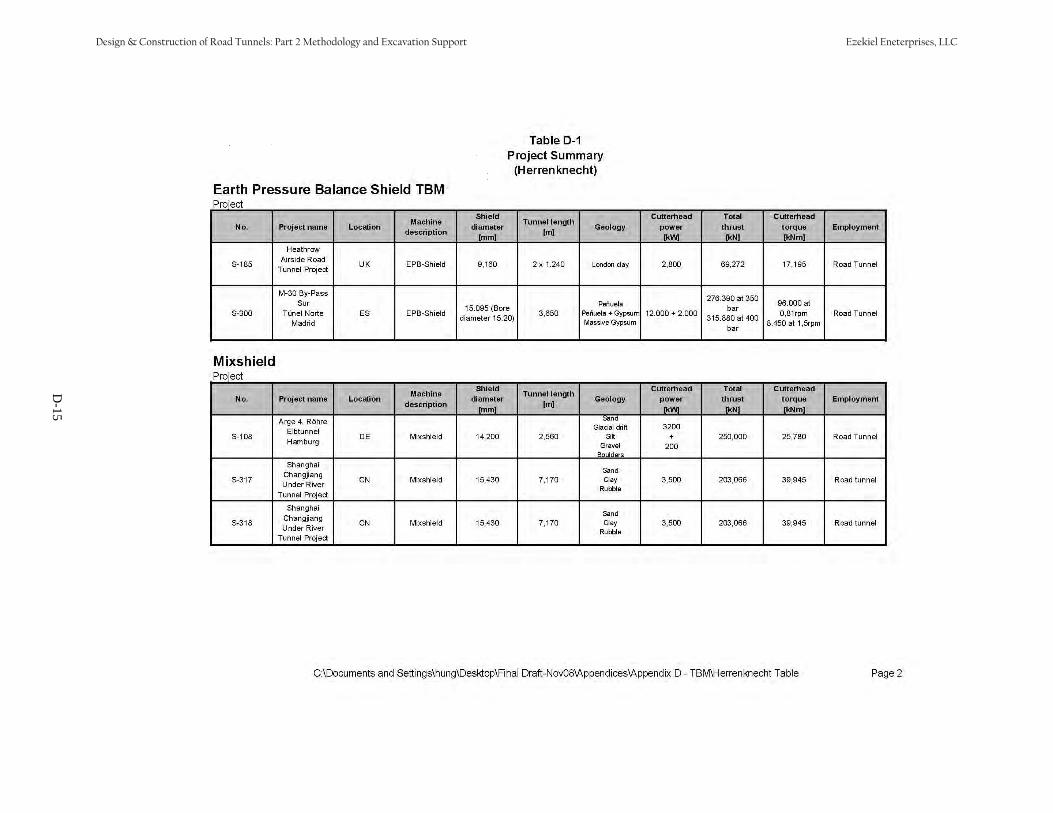
D-15
Design & Construction of Road Tunnels: Part 2 Methodology and Excavation Support Ezekiel Eneterprises, LLC

Appendix E
Analytical Closed Form Solutions
Design & Construction of Road Tunnels: Part 2 Methodology and Excavation Support Ezekiel Eneterprises, LLC
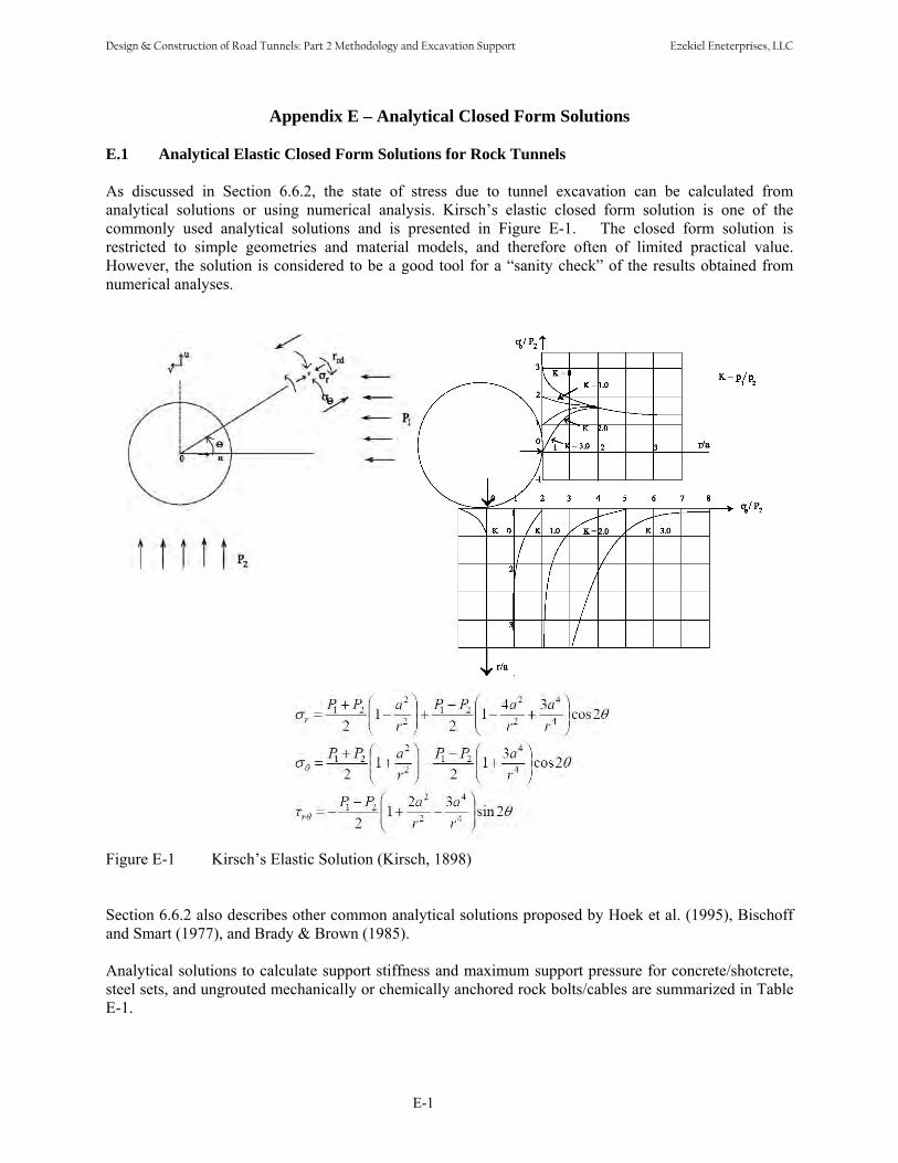
Appendix E – Analytical Closed Form Solutions
E.1 Analytical Elastic Closed Form Solutions for Rock Tunnels
As discussed in Section 6.6.2, the state of stress due to tunnel excavation can be calculated from analytical solutions or using numerical analysis. Kirsch’s elastic closed form solution is one of the commonly used analytical solutions and is presented in Figure E-1. The closed form solution is restricted to simple geometries and material models, and therefore often of limited practical value. However, the solution is considered to be a good tool for a “sanity check” of the results obtained from numerical analyses.
Figure E-1 Kirsch’s Elastic Solution (Kirsch, 1898)
Section 6.6.2 also describes other common analytical solutions proposed by Hoek et al. (1995), Bischoff and Smart (1977), and Brady & Brown (1985).
Analytical solutions to calculate support stiffness and maximum support pressure for concrete/shotcrete, steel sets, and ungrouted mechanically or chemically anchored rock bolts/cables are summarized in Table E-1.
E-1
Design & Construction of Road Tunnels: Part 2 Methodology and Excavation Support Ezekiel Eneterprises, LLC

Table E-1 Analytical Solutions for Support Stiffness and Maximum Support Pressure for Various Support Systems (Brady & Brown, 1985)
Support System Support stiffness (K) and maximum support pressure (Pmax) 2 2E [r − (r − t ) ]c i i cK = 2 2(1+ν ) ([1− 2ν )r + (r − t ) ]Concrete /Shotcrete lining c c i i c
2σ ⎡ (r − t ) ⎤cc i cP =max ⎢1− ⎥22 ⎢ r⎣ i ⎥⎦31 Sr Sr ⎡θ (θ + sinθ cosθ )⎤ 2S tθi i B= + +2 2K E A E I ⎢⎣s s s s 2sin θ ⎥⎦Blocked steel sets EBW
3A I σs s ysP = max 2Srθ{3I + XA [r − (t + 0.5X )](1− cosθ )i s s i B
1 s s ⎛ 4l ⎞c lUngrouted mechanically or = ⎜ +Q⎟⎜ 2 ⎟K d Echemically anchored rock bolts or ri ⎝ π b b ⎠cables TbfP =max scsl
NOTATION: K = support stiffness; Pmax = maximum support pressure; Ec = Young’s modulus of concrete; tc = lining thickness; ri = internal tunnel radius; σcc = uniaxial compressive strength of concrete or shotcrete; W = flange width of steel set and side length of square block; X = depth of section of steel set; As = cross section area of steel set; Is = second moment of area of steel set; Es = Young’s modulus of steel; σys = yield strength of steel; S = steel set spacing along the tunnel axis; θ= half angle between blocking points in radians; tB = thickness of block; EB = Young’s modulus of block material; l = free bolt or cable length; db = bolt diameter or equivalent cable diameter; Eb = Young’s modulus of bolt or cable; Tbf = ultimate failure load in pull-out test; sc = circumferential bolt spacing; sl = longitudinal bolt spacing; Q = load-deformation constant for anchor and head.
E.2 Analytical Elastic Closed Form Solutions for Ground Support Interaction
Analytical solutions for ground-support interaction for a tunnel in soil are available in the literatures. The solutions are based on two dimensional, plane strain, linear elasticity assumptions in which the lining is assumed to be placed deep and in contact with the ground (no gap), i.e., the solutions do not allow for a gap to occur between the support system and ground. The background information for the common closed form models are presented in Appendix B of the FHWA Tunnel Design Guidelines (2004) which is reproduced here in Section E.3 for convenience.
Early analytical solutions by Burns and Richard (1964), Dar and Bates (1974), and Hoeg (1968) were derived for the overpressure loading, while solutions by Morgan (1961), Muir Wood (1975), Curtis (1976), Rankin, Ghaboussi and Hendron (1978), and Einstein et al. (1980) were for excavation loading. Solutions are available for the full slip and no slip conditions at the ground-lining interface. Appendix E present the available published analytical solutions in Table E-2. A sample analysis is presented in Table E-3 to illustrate the applications of various closed-form solutions for a 22ft diameter circular tunnel with1.5 ft thick concrete lining. The tunnel is located at 105 ft deep from the ground surface to springline andgroundwater table is located 10 ft below the ground surface. Details of input parameters are shown inTable E-3a. The calculated lining loads from various analytical solutions are presented in Table E-3b.
E-2
Design & Construction of Road Tunnels: Part 2 Methodology and Excavation Support Ezekiel Eneterprises, LLC

Table E-2 Analytical Solutions for Soil – Liner Interaction Analytical Solutions Thrust Moment
crown = P + P + Pd s w
Springline = P + P − Pd w s
1997
) (
Relaxation P = −0.5 ⋅ + k ⋅ +C ⋅ h ⋅γd (1 1/ 10 ) ( ( ) ) ( m
P = 0.5 ⋅ − k ⋅ + F ⋅ h γ⋅ −s (1 1/ 10 ) ( ( )) ( m
− h ⋅γ ⋅w w ) (h ⋅γ ⋅ dw w ) (
d / 2
/ 2)) ( 1/ 4= − ) (⋅ 1−k0 ) ⋅( (1/ 1+F)) ⋅(h γ⋅ s −hw γ⋅ w ) (⋅ d )2/ 2
Pen
zien
P = − +C ⋅h ⋅γ ⋅ dw ( (1/ 1 )) w w ( / 2)
Crown = P + P + Pd s w
Wu
& Springline = P + P − Pd w s
Overburden dP = −(1+ 0k ) (⋅ 1− mν ) (/ 1
wP = −( (1/ 1+C )) ⋅ wh ⋅ wγ ⋅
+C ) (⋅ h ⋅ sγ − wh ⋅ wγ ) (⋅ d / 2)(d / 2)
= −(1−k0 ) (⋅ 1 ν− m ) (/ ( 3−4 ν⋅ m ) (⋅ 1+F )) ⋅(h γ⋅ m −hw γ⋅ w ) (⋅ )2/ 2
sP = ( ⋅(2 1− 0k ) (⋅ 1− mν )) / ((3− 4 ⋅ mν ) (⋅ 1+ F)) (⋅ h ⋅ mγ − wh ⋅ wγ )) (⋅ d / 2)
Ein
stei
n &
Sch
war
tz (1
979)
Excavation full slip
Crown
springline
=
=
⎡0.5⎣⎡0.5⎣
⋅
⋅
(1
(1+
+
k0
k0
) (⋅ 1
) (⋅ 1
−
−
a0
a0
))
−
+
((0.5
0.5
⋅ (1+
(1⋅ +
k0
k0
) (⋅ 1−
) (1⋅ −
2
2
⋅
⋅
a2
a2
))⎤ ⋅(γ⎦ m
)) (⎤ ⋅ γ⎦ m
⋅
⋅
h d⋅
h d⋅
/ 2) / 2)
0.5= − (1⋅ − k0 ) (1⋅ − 2 ⋅a2 ) ⋅ (γ ⋅h ⋅ (d 2/ 2) )
Excavation no slip
Thrust at Crown = ⎡0.5 (1⋅ + k 1⋅ − a⎣ 0 ) ( 0 )
Thrust at Springline = ⎡0.5 (1⋅ + k ⋅ 1−a +⎣ 0 ) ( 0 )
− (0.5 (1⋅ −
(0.5 (1⋅ − k0
k 1⋅ +0 ) (
) (1⋅ + 2 ⋅
2 ⋅
a4
a ⎤ ⋅ γ ⋅h d⋅ / 24 )) (⎦ m )
)) (⎤ ⋅ γ ⋅h D⋅ / 2⎦ m )
= − ⎡0.25⎢⎣⋅ (1− k0 ) (⋅ 1− 2 ⋅h + 2 ⋅b2 ) ⋅ (γ ⋅h ⋅ (D / 2 2) )
0a C F= ⋅ ⋅(1− mν ) / (F C+ + (C F⋅ ⋅ (1− mν )))2a = (F + ) (6 1⋅ − mν ) (/ 2 ⋅F ⋅ (1− mν ) + (6 ⋅ (5− 6 ⋅ mν
4a β= ⋅ 2b
β = ((F + ) (6 1⋅ − mν ) (+ 2 ⋅F C⋅ )) (/ 3⋅F + 3⋅C + 2 ⋅
)))
C F⋅ ⋅ (1− mν ))
2b
C
F
=
=
=
⎡C ⋅ (1− ⎤ ⎡⎣ mν ) / 2 ⋅ (C ⋅ (1−⎦ ⎣ mν
2⎡(d / 2) ⋅ ⋅ − ⎤ ⎡⎣ mE (1 Lν ) / E⎦ ⎣ L ⋅
3 2(d / 2) ⋅ mE ⋅ (1− Lν ) / (EL ⋅ I
) + 4 ⋅ mν − 6 ⋅ β −3⋅ β ⋅2( ⋅ − ⎤
LA / Lw ) (1 mν )⎦21⋅ ( m−ν ))
C ⋅ (1− mν )
Peck, Hendron & Moharaz (1972)
overburden
Thrust at Crown = 0.5 ⋅ ⎡(1+ k ⋅b⎣ 0 ) 1
Thrust at Springline = 0.5 ⋅ ⎡(1+ k ⋅b⎣ 0 ) 1
−
+
0.3333
0.3333
⋅
⋅
(1
(1
−
−
k0
k0
)
)
⋅
⋅
b2
b2
⎤⎦
⎤⎦
γ⋅ s
⋅γ s
⋅
⋅
h
h
⋅
⋅
(
(
d
d
/ 2
/ 2
)
)
(1= − k0 ) ⋅b2 γ⋅ s ⋅h ⋅ (d / 2)2 / 6
b1 1= − a1 2b (1 3= + ⋅ 2a − 4 ⋅ 3a )a1 (1 2= − ⋅ mν ) (⋅ C − )1 / ((1− 2 ⋅ mν ) ⋅C + )1 2a
= ((2 ⋅F ) +1− 2 ⋅ mν ) (/ 2 ⋅F + 5− 6 ⋅ mν ) 3a = (2 ⋅F ) (/ 2 ⋅F + 5− 6 ⋅ mν )
E-3
Design & Construction of Road Tunnels: Part 2 Methodology and Excavation Support Ezekiel Eneterprises, LLC

Ran
ken,
Gha
bous
si a
nd H
endr
on (1
978)
Overpressure
(no slip)
Thrust at Crown = (γ ⋅ ⋅(h d / 2)) ⋅ (
Thrust at Springline = (γ ⋅ ⋅(h d / 2)) ⋅ (
(
(
(1
(1
+
+
k0
k0
) (⋅ 1
) (⋅ 1
−
−
Ln
Ln
)
)
)
)
−
+
(
(
(1
(1
−
−
k0
k0
) (⋅ 1
) (⋅ 1
+
+
J
J
n
n
)
)
)
)
)
)
Moment at Crown 2= (γ ⋅ ⋅(h d / 2) / 2) ⋅ ⎡(1+⎣ 0k ) (1⋅ − 2 ⋅ mν
Moment at Springline 2= (γ ⋅ ⋅(h d / 2) / 2) ⋅ ⎡(1+ k⎣ 0 ) (⋅ 1 2− ⋅ mν
)
)
⋅
⋅
(
(
C
C
(/ 6
(/ 6
⋅
⋅
F
F
)) (1⋅ −
)) ⋅(1−
nL
nL
)
)
−
+
(
(
(1−
(1−
k
k
)
)
/ 2) (1⋅ −
/ 2) ⋅ (1−
Jn
Jn
− 2 ⋅
2− ⋅
N
N
⎤⎦
⎤⎦
Overpressure (full slip)
Thrust at Crown = ((1+ k ⋅ 1− L0 ) ( f
Thrust at Springline = ((1+ k 1⋅ − L0 ) ( f
) − (1
) (+ 1
−
−
k0
k0
)
)
⋅ (1−
(1⋅ −
J
J
f
f
))
))
⋅γ ⋅
⋅γ ⋅
h
h
⋅
⋅
(
(
d
d
/ 4)
/ 4)
Moment at Crown 2= ⋅ ⋅ ⋅ ⎡(γ (h d / 2) / 2) (1+⎣
Moment at Springline 2= ⋅ ⋅ ⋅ ⎡(γ (h d / 2) / 2) (1+⎣
0k
k0
) (⋅ 1−
) (1⋅ −
2
2
⋅ mν
⋅ mν
)
)
⋅
⋅
(C
(C
(/ 6
(/ 6
⋅
⋅
F
F
)) (1⋅ −
)) (1⋅ −
Lf
nL
) (− 1− k
) (+ 1− k
) (1⋅ −
) (1⋅ −
J
J
)⎤⎦
)⎤⎦
Excavation (No Slip)
Thrust at Crown *= ((1+ k 1⋅ − L0 ) ( n
Thrust at Springline *= ((1+ k 1⋅ − L0 ) ( n
)
)
−
+
(1
(1
−
−
k0
k0
)
)
(1⋅ −
(1⋅ −
J
J
*n
*n
)
)
)
)
γ⋅ ⋅
γ⋅ ⋅
h
h
⋅
⋅
(
(
d
d
/ 4)
/ 4)
Moment at Crown 2= ⋅ ⋅ ⋅ ⎡(γ (h d / 2) / 2) (1⎣
Moment at Springline 2= ⋅ ⋅ ⋅ ⎡(γ (h d / 2) / 2) (1⎣
+
+
0k
k0
)
)
⋅
⋅
(
(
*nL
*nL
(/ 6
(/ 6
⋅
⋅
F
F
)
)
)
)
−
+
(
(
0.5
0.5
⋅
⋅
(1
(1
−
−
0k
k0
)
)
⋅
⋅
(1
(1
+
+
J
J
−
−
N
N
⎤))⎦⎤))⎦
Excavation (Full Slip)
Thrust at Crown *= ((1+ k 1⋅ − L0 ) ( f
Thrust at Springline *= ((1+ k ⋅ 1− L0 ) ( f
) (− 1−
) + (1−
k0
k0
) (1⋅ −
) ⋅ (1−
2 ⋅
2 ⋅
J
J
* γ⋅ ⋅h ⋅ df )) (
* γ⋅ ⋅h ⋅ df )) (
/ 4)
/ 4 )
` Moment at Crown
2= (γ ⋅ ⋅ (h d / 2) / 2) ⋅
Moment at Springline 2= (γ ⋅ ⋅ (h d / 2) / 2) ⋅
⎡(1+⎣
⎡(1+⎣
k0
k0
)
)
⋅
⋅
(
(
Lf
Lf
*
*
(/ 6
(/ 6
⋅
⋅
F
F
))
))
−
+
((1−
((1−
k0
k0
) (⋅ 1−
) ⋅(1−
2 ⋅
2 ⋅
J
J
⎤))⎦⎤))⎦
nL (1 2= − ⋅ mν ) (⋅ C − ) (1 / 1+ (1 2− ⋅ mν )⋅C )Jn (1 2= − ⋅ mν ) (⋅ 1−C ) ⋅F − (0.5 ⋅ (1 2− ⋅ mν )⋅C + 2)
*nL (1 2= − ⋅ mν ) ⋅C (/ 1+ (1− 2 ⋅ mν ) ⋅C )
*J = ⎡n (2 ⋅⎣ mν + (1− 2 ⋅ mν ) ⋅C ) ⋅F + (1− mν ) (⋅ 1− 2 ⋅ mν ) ⋅C
/ ⎡((3 2− ⋅⎣ mν ) (+ 1 2− ⋅ mν ) ⋅ )C F⋅ + (0.5 ⋅ (5− 6 ⋅ mν )) (⋅ 1 2− ⋅ mν ) ⋅C + (6−8 ⋅ mν )⎤⎦ / ⎡((3 2 ν− ⋅ + ν− ⋅ ⋅C F⋅ + ⋅ − ν⋅ ⋅ ν⎣ m ) (1 2 m ) ) (0.5 (5 6 m )) (1 2− ⋅ m ) ⋅C + (6−8 ⋅ ⎤⎦
Nn = (( + (1 1 2− ⋅ mν ) ⋅C ) ⋅F − (0.5 ⋅ (1 2− ⋅ mν ) ⋅C ) − 2)/ ⎡((3 2− ⋅⎣ mν ) (+ 1 2− ⋅ mν ) ⋅ )C F⋅ + (0.5 ⋅ (5− 6 ⋅ mν )) (⋅ 1
L = − ν⋅ ⋅ C − + − ν⋅ ⋅Cf (1 2 m ) ( ) (1 / 1 (1 2 m ) )J = ⋅F + − ν⋅ ⋅F + − ν⋅f (2 (1 2 m )) (/ 2 (5 6 m ))N = ⋅F − ⋅F + − ν⋅f (2 ) (1 / 2 (5 6 m ))
2− ⋅ mν ) ⋅C + (6−8 ⋅ mν )⎤⎦
*N = ⎡n (3 2+ (1⋅ − 2 ⋅⎣ mν ) ⋅C ) ⋅F + (0.5 (1⋅ − 2 ⋅ mν ) ⋅C )/ ⎡((3 2 ν− ⋅ + ν− ⋅ ⋅C F⋅ + ⋅ − ν⋅ ⋅ ν⎣ m ) (1 2 m ) ) (0.5 (5 6 m )) (1 2− ⋅ m
*L = − ν⋅ ⋅C + − ν⋅ ⋅Cf (1 2 m ) (/ 1 (1 2 m ) )*J = F + ν− ⋅F + − ν⋅f ( (1 m )) (/ 2 (5 6 m ))*N = ⋅F + ⋅F + − ν⋅f (4 ) (1 / 2 (5 6 m ))
) ⋅C + (6−8 ⋅ ⎤⎦
Muir & Wood (1975)
Excavation
Thrust at Crown =1/ 3⋅ (σ −σ ⋅ d + ⋅λ ⋅ d + σ −σv H ) ( / 2) (4 / 3) (deflection) (/ / 2) ( v H
Thrust at Springline = 2 / 3⋅k ⋅ σ −σ ⋅ d / 2 + 2 / 3 ⋅λ ⋅ deflection ⋅ d / 2 + σ0 ( v H ) ( ) ( ) ( ) ( ) ( H
) (⋅ d
) (⋅ d
/ 2 )
/ 2 )
2 = ( vσ − Hσ ) / 6 ⋅ (dη = ( IDφ + d ) (/ 2 ⋅d
2/ 2))
2η⋅ ⋅ sR (/ 1+ sR )
E-4
Design & Construction of Road Tunnels: Part 2 Methodology and Excavation Support Ezekiel Eneterprises, LLC

Full Slip k (1= − mν ) / ((1− 2 ⋅ mν ) (⋅ 1+ mν ))β = ( m /E EL ) (⋅ d / 2 ⋅ ) (η / LA / Lw )η = ( IDφ + d ) (/ d / 2)
λ (3= ⋅ mE ) / ((1+ mν ) (⋅ 5− 6 ⋅ mν ) ⋅d / 2)3
1Q = ( mE / LE ) ⋅ ( (1/ 1+ mν )) ⋅(η ⋅(d / 2) (/ 12
32Q = ( mE / LE ) ⋅ ( (1/ 1+ mν )) (⋅ ( d / 2) (/ 12 ⋅ I
⋅ I
)))) Rs
σ H
3 4(9= ⋅EI ) / (λ η⋅ ⋅(d / 2)= σ ⋅k + H ⋅γ ⋅ 1− kv 0 w w ( 0
))
IDφ = (d / 2− tL ) ⋅2 3I = ( Lw ⋅ tL ) /12 / Lw σ v = γ ⋅h S+m
Thrust at Crown = N − Nconstant max
Excavation Full Slip
Thrust at Springline = N + Nconstant max
N = ⎡ σ +σconstant (⎣ v H ) ⋅d / 2 / 2⎤ ⎡⎦ ⎣ + (1− k0 ) ⋅2 ⋅k ⋅ β ⎤⎦
= − 1/ 2⎡⎣ ⋅(σ v −σ H ) 2η⋅ ⋅(d / 2 2) ⎤⎦ ⋅ (3− 4 ν⋅ m ) (/ 5− 6 ν⋅ m + 4 ⋅ 2
)
N = − ⋅max (( vσ Hσ ) d / 4) (⋅ 3− 4 ⋅ −mν ) (/ 5 6 ⋅ +mν 4 ⋅ 1Q )Thrust at Crown
(197
6)
= N − Nconstant max
Cur
tis Excavation
No Slip
Thrust at Springline = N + Nconstant max
N = ⎡constant (⎣ vσ + Hσ ) ⋅d / 2 / 2⎤ ⎡ +⎦ ⎣ (1− 0k ) ⋅2 ⋅k ⋅ β ⎤⎦
= − 1/ 4⎡⎣ ⋅(σ v −σH ) 2η⋅ ⋅(d 2/ 2) / 1⎤ ⎡⎦ ⎣ +Q2 ⋅ (3− 2 ν⋅ m )⎤⎦
N = σ −σ ⋅dmax (( v H ) / 2) ⋅ ⎡(1+ (2⎣ ν⋅ m ⋅Q1 )) (⋅ 3− 4 ν⋅ m ) (⋅ 1+Q1 )⎤⎦ k (1 ν= − − ν⋅ ⋅ ν+m ) / ((1 2 m ) (1 m ))β = ( /E E ⋅ d η⋅ A wm L ) ( / 2 ) (/ /L L )η = (φ + d dID ) (/ / 2)
λ (3= ⋅ mE ) / ((1+ mν ) (⋅ 5− 6 ⋅ mν ) ⋅d / 2)3
1Q = ( mE / LE ) ⋅ ( (1/ 1+ mν )) ⋅(η ⋅(d / 2) (/ 12
32Q = (Em / EL ) ⋅ ( (1/ 1+ mν )) (⋅ ( d / 2) (/ 12 ⋅ I
⋅
)
I
)))
φ = d − t ⋅ID ( / 2 L ) 2
3I = ( Lw ⋅ tL ) /12 / Lw
NOTATION: νm : Poisson's ration for ground AL : Cross-Sectional Area of Liner F : Flexibilityν L : Poisson's ration for Liner γ m : Ground Unit Weight k0 : Coefficient of Lat. Earth PressureEm : Young's Modulus for ground γ w : Water Unit Weight h : Depth to SpringlineEL : Young's Modulus for Liner d : Diameter of Tunnel hw : Depth from Water TabletL : Thickness of Liner I : Moment Inertia per Unit Length Rs : Stiffness FactorwL : Width of Liner C : Compressibility S : Surcharge
E-5
Design & Construction of Road Tunnels: Part 2 Methodology and Excavation Support Ezekiel Eneterprises, LLC
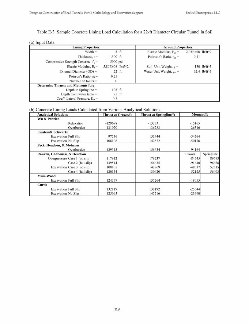
Table E-3 Sample Concrete Lining Load Calculation for a 22-ft Diameter Circular Tunnel in Soil
(a) Input DataLining Properties: Ground Properties
Width = 5 ft Elastic Modulus, Em = 2.03E+06 lb/ft^2Thickness, t = 1.500 ft Poissson's Ratio, nm = 0.41
Compressive Strength Concrete, f'c = 5000 psiElastic Modulus, El = 5.80E+08 lb/ft^2 Soil Unit Weight, g = 130 lb/ft^3
External Diameter (OD) = 22 ft Water Unit Weight, gw = 62.4 lb/ft^3Poisson's Ratio, nl = 0.25Number of Joints = 0
Determine Thrusts and Moments for:Depth to Springline = 105 ft
Depth from water table = 95 ftCoeff. Lateral Pressure, K0 = 0.7
(b) Concrete Lining Loads Calculated from Various Analytical SolutionsAnalytical Solutions Thrust at Crown/ft Thrust at Springline/ft Moment/ftWu & Penzien
RelaxationOverburden
-129698-131020
-132731-136283
-15165-26316
Einstein& SchwartzExcavation Full SlipExcavation No Slip
97536108108
153444142872
-54264-50176
Peck, Hendron, & MoharazOverburden 139515 156634 -94164
Ranken, Ghaboussi, & HendronOverpressure Case 1 (no slip)
Case 2 (full slip)Excavation Case 3 (no slip)
Case 4 (full slip)
117912139514108105120554
178237156635142869130420
Crown-84545-91640-48037-52125
Springline89593966885231556403
Muir-WoodExcavation Full Slip 124377 137264 -18055
CurtisExcavation Full SlipExcavation No Slip
132119125095
138192145216
-25644-23690
E-6
Design & Construction of Road Tunnels: Part 2 Methodology and Excavation Support Ezekiel Eneterprises, LLC
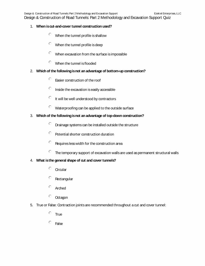
Design & Construction of Road Tunnels: Part 2 Methodology and Excavation Support Ezekiel Enterprises, LLC
Design & Construction of Road Tunnels: Part 2 Methodology and Excavation Support Quiz
1. When is cut-and-cover tunnel construction used?
o When the tunnel profile is shallow
o When the tunnel profile is deep
o When excavation from the surface is impossible
o When the tunnel is flooded
2. Which of the following is not an advantage of bottom-up construction?
o Easier construction of the roof
o Inside the excavation is easily accessible
o It will be well understood by contractors
o Waterproofing can be applied to the outside surface
3. Which of the following is not an advantage of top-down construction?
o Drainage systems can be installed outside the structure
o Potential shorter construction duration
o Requires less width for the construction area
o The temporary support of excavation walls are used as permanent structural walls
4. What is the general shape of cut and cover tunnels?
o Circular
o Rectangular
o Arched
o Octagon
5. True or False: Contraction joints are recommended throughout a cut and cover tunnel:
o True
o False

Design & Construction of Road Tunnels: Part 2 Methodology and Excavation Support Ezekiel Enterprises, LLC
Design & Construction of Road Tunnels: Part 2 Methodology and Excavation Support Quiz
6. Which is not one of the three basic methods used in the design of cut and cover tunnel
structures?
o Load and resistance factor design
o Service resistance factor design
o Load factor design
o Service load design
7. When will excavations require a dewatering system?
o They always require a dewatering system
o When the groundwater levels are higher than the base level of the tunnel
o When the base level of the tunnel is higher than the groundwater levels
o None of the above
8. True or False: During rock tunneling, failure occurs when the stress within the surrounding mass
rock exceeds the strength of the rock mass:
o True
o False
9. According to Terzaghi’s Rock mass Classification, which of the following is not a rock
condition?
o Stratified rock
o Holding rock
o Swelling rock
o Blocky and seamy rock
10. When blasting rock, why is it optimal to have a free face available?
o So the rock remains fractured, but not fragmented
o So the fragments have a place to move into after the blast
o So a chemical reaction can be created between the rocks
o To create the perfect clay
Design & Construction of Road Tunnels: Part 2 Methodology and Excavation Support Ezekiel Enterprises, LLC
Design & Construction of Road Tunnels: Part 2 Methodology and Excavation Support Quiz
11. What is a major difference between tunnel blasting and surface blasting?
o Drill holes are not possible for tunnel blasting
o Tunnel blasting usually only has one free face available to provide relief
o The upper heading is blasted last and the rest of the rock is taken with boreholes
o Surface blasting usually only has one free face available to provide relief
12. What is a TBM?
o Top boring machine
o Tunnel breaking machine
o Tunnel boring machine
o Tunnel bridge maintenance
13. What are the two general categories for TBMs?
o Cutter & Segment
o Gripper & Cutter
o Closed Gripper & Segment
o Gripper & Segment
14. Generally, when should a roadheader be considered?
o Short runs, one of a kind openings
o Low to moderate abrasivity
o Nominal water pressure
o All of the above

Design & Construction of Road Tunnels: Part 2 Methodology and Excavation Support Ezekiel Enterprises, LLC
Design & Construction of Road Tunnels: Part 2 Methodology and Excavation Support Quiz
15. What can be considered for the initial support system in a rock tunnel?
o Lattice girders
o Cables
o Steel ribs
o All of the above
16. Pre-support is used in both rock and soil tunnels, but somewhat more frequently in:
o Fiberglass tunnels
o Clay tunnels
o Rock tunnels
o Soil tunnels
17. Which method of groundwater control is the most common?
o Grouting
o Freezing
o Drainage ahead of face from probe holes
o Dewatering at the tunnel face
18. True or False: An undrained system is more costly than a drained system:
o True
o False
19. Which soil classification is described by this behavior: Ground absorbs water, increases in
volume, and expands slowly into the tunnel.
o Flowing
o Squeezing
o Raveling
o Swelling
Design & Construction of Road Tunnels: Part 2 Methodology and Excavation Support Ezekiel Enterprises, LLC
Design & Construction of Road Tunnels: Part 2 Methodology and Excavation Support Quiz
20. Which soil classification typically has this type of soil: Below the water table ins silt, sand, or
gravel without enough clay content to give significant cohesion and plasticity.
o Flowing
o Swelling
o Firm
o Running
21. Which is a principle that must be observed when following the Sequential Excavation Method
(SEM)?
o The completion of the invert gives the ring-like structure the static properties of a
tube
o The geotechnical behavior must be taken into account
o General, control, geotechnical measurements and constant checks on the
optimization of the pre-established support means must be performed
o All of the above
22. Which is not a main objective of tunnel support systems?
o Stabilize the tunnel heading
o Minimize ground movements
o Permit the tunnel to operate over the design life
o Ensure the ground has space to move over time
23. In order to perform a numerical analysis for tunneling, how many steps are recommended?
o 6
o 7
o 8
o 9

Design & Construction of Road Tunnels: Part 2 Methodology and Excavation Support Ezekiel Enterprises, LLC
Design & Construction of Road Tunnels: Part 2 Methodology and Excavation Support Quiz
24. True or False: Ground settlement is of greater concern for soft ground tunnels than rock
tunnels:
o True
o False
25. In order, briefly describe architectural damage, functional damage, and structural damage:
o Damage affecting the use, damage affecting the stability, damage to the
appearance
o Damage to the appearance, damage affecting the stability, damage affecting the
use
o Damage affecting the stability, damage to the appearance, damage affecting the
use
o Damage to the appearance, damage affecting the use, damage affecting the
stability
26. Which of the following is a type of grouting?
o Jet
o Compensation
o Compaction
o All of the above
27. What are the factors that make tunneling difficult?
o Instability, heavy loading, physical conditions, equipment failure
o Instability, heavy loading, obstacles and constraints, physical conditions
o Physical conditions, equipment failure, freezing, instability
o Physical conditions, freezing, heavy loading, obstacles and constraints
28. True or False: Any amount of flowing groundwater through the working face is sufficient to
permit the start of a run, which can develop into a total collapse?
o True
o False
Design & Construction of Road Tunnels: Part 2 Methodology and Excavation Support Ezekiel Enterprises, LLC
Design & Construction of Road Tunnels: Part 2 Methodology and Excavation Support Quiz
29. Which is a typical obstacle when drilling a tunnel?
o Boulders
o Abandoned foundations of other facilities
o Karstic limestone
o All of the above
30. Safety rules require that action be taken when methane is present in concentrations of ____
of the lower explosive limit:
o 10%
o 15%
o 25%
o 20%