design and construction of single- phase...
TRANSCRIPT

"DESIGN AND CONSTRUCTION OF SINGLE-
PHASE TRANSFORMATION MODULES THAT
ALLOW TO ANALYZE THE UTILITY AND
APPLICATION OF THE DIFFERENT THREE-
PHASE CONNECTION GROUPS" Jaime David Yucato Checa Gabriela Marcel Revelo Erazo
Technical University of North, Faculty of Engineering in Applied Sciences
[email protected] [email protected]
Summary — The present project indicates the implementation
of three didactic modules for the analysis of connection groups
of three-phase transformers, vacuum and short circuit tests,
polarity and voltage regulation. In the first part we describe all
the information necessary for the training of the students, such
as generalities of the transformer, vacuum test, short circuit test,
and the different connection groups. A second part describes
the design and construction of the three single-phase didactic
transformation modules that allow us to analyze the utility and
application of the three-phase connection groups. Finally, the
recommendations and conclusions of the project are
mentioned.
I. INTRODUCTION
The experiments of Faraday began in 1831, that is to say,
half a century before the invention of the transformer. If we
ask why this delay is due to its appearance, the answer is
relatively simple: at the beginning of electricity, this occurred
in its continuous form and in that case the transformer was not
necessary.
It was not until later as when problems began to appear
concerning the transportation of electricity and the energy
losses that occurred in the form of heat, when the transformer
appears as an extremely useful device. The electric
transformer was the answer with which the technology of that
time solved the problem, which allowed that it continued the
impetuous development of what today is known like progress.
The transformer is a device that is based on the phenomenon
of electromagnetic induction. It consists of two coils of
conductive material wound on a closed core of ferromagnetic
material, but isolated from each other electrically. The only
connection between the coils is the common magnetic flux
that sets in the core. The core is generally made of a
ferromagnetic material that facilitates the circulation of the
magnetic field.
In the development of this project is intended to build a tool
for students of electrical engineering in order to achieve
practical knowledge and to obtain a more efficient
development for the professional field.
II. CONTENT DEVELOPMENT
The contents in this project are structured in such a way that
in a first part the generalities of the programmable automata
are explained, then apply the selection parameters and
perform the construction and implementation of the didactic
module.
A. Overview
A transformer is a device that changes the alternating
electrical power with a voltage level to alternating electric
power with another level of voltage by the action of a
magnetic field. "See [1]"
B. Transformer operation
A transformer operates with the principle of electromagnetic
induction, two coils are assembled inductively, the magnetic
flux passes through one of them. Also partly or wholly by the
other, resulting in the two coils having a common magnetic
circuit. "See [1]"
C. Types of transformers
Single-phase column transformer. Has a rectangular shape
and consists of two columns where windings are wound,
all of the same section.
Single-phase armored transformer consisting of a
magnetic core with three columns, the central one being
double section compared to the lateral ones. The two windings
are wound on the central column, one on top of the other and
with an intermediate insulation layer. "See [7]"
D. Regulation of voltage in a transformer
Voltage regulation at full load is an amount that compares
the output voltage of an unloaded transformer (vacuum) to the
output voltage at full load. "See [1]"
E. Testing of transformers
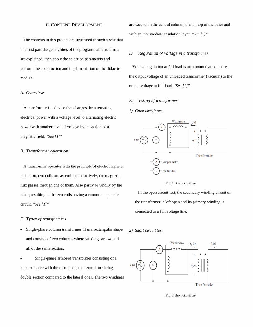
1) Open circuit test.
Fig. 1 Open circuit test
In the open circuit test, the secondary winding circuit of
the transformer is left open and its primary winding is
connected to a full voltage line.
2) Short circuit test
Fig. 2 Short circuit test
This test is carried out by placing the secondary winding in
a short circuit and supplying the primary with an adjustable
voltage, starting from zero and increasing until the nominal
current is reached.
These two tests serve to make the circuit equivalent to its
minimal expression. "See [1], [7]"
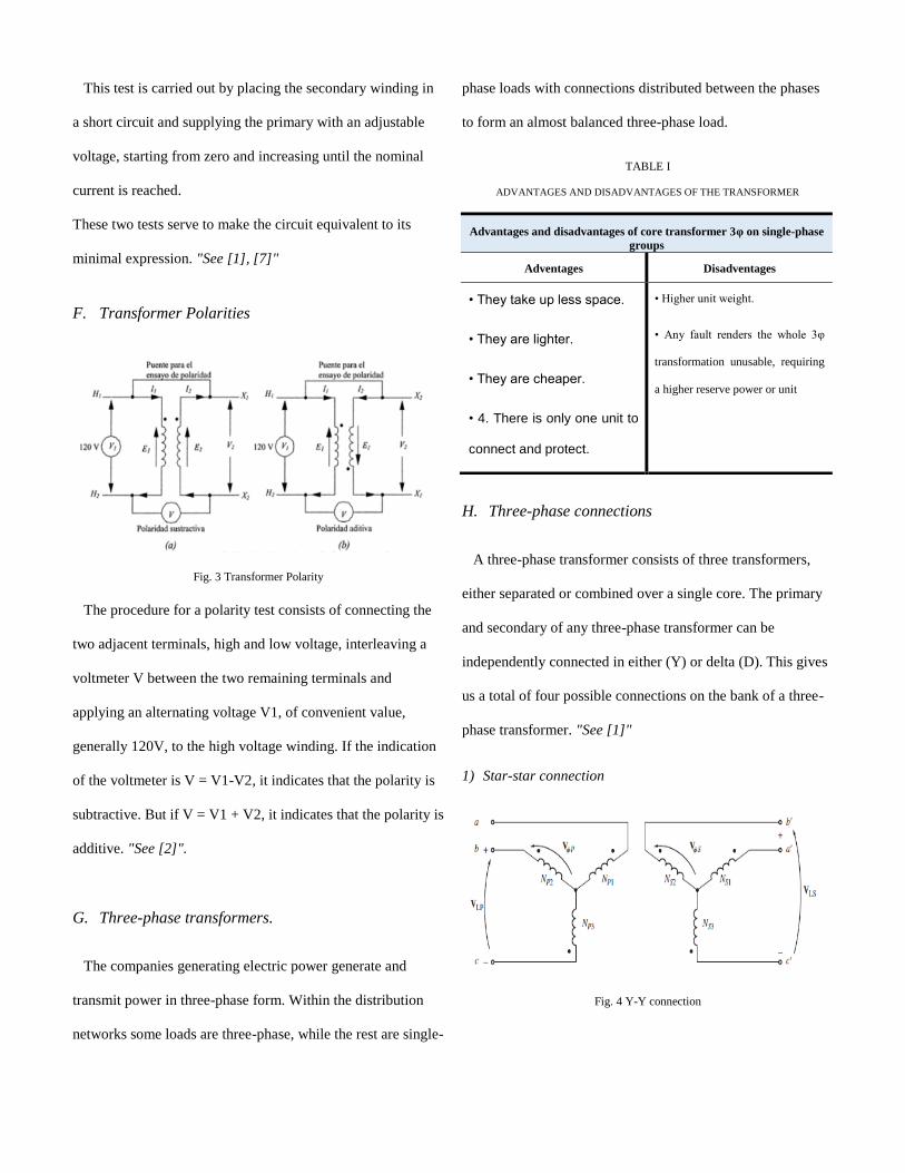
F. Transformer Polarities
Fig. 3 Transformer Polarity
The procedure for a polarity test consists of connecting the
two adjacent terminals, high and low voltage, interleaving a
voltmeter V between the two remaining terminals and
applying an alternating voltage V1, of convenient value,
generally 120V, to the high voltage winding. If the indication
of the voltmeter is V = V1-V2, it indicates that the polarity is
subtractive. But if V = V1 + V2, it indicates that the polarity is
additive. "See [2]".
G. Three-phase transformers.
The companies generating electric power generate and
transmit power in three-phase form. Within the distribution
networks some loads are three-phase, while the rest are single-
phase loads with connections distributed between the phases
to form an almost balanced three-phase load.
TABLE I
ADVANTAGES AND DISADVANTAGES OF THE TRANSFORMER
H. Three-phase connections
A three-phase transformer consists of three transformers,
either separated or combined over a single core. The primary
and secondary of any three-phase transformer can be
independently connected in either (Y) or delta (D). This gives
us a total of four possible connections on the bank of a three-
phase transformer. "See [1]"
1) Star-star connection
Fig. 4 Y-Y connection
Advantages and disadvantages of core transformer 3φ on single-phase
groups
Adventages Disadventages
• They take up less space.
• They are lighter.
• They are cheaper.
• 4. There is only one unit to
connect and protect.
• Higher unit weight.
• Any fault renders the whole 3φ
transformation unusable, requiring
a higher reserve power or unit

Used when it is desired to have neutral at low and when
large currents of imbalance (neutral phase) are not foreseen.
Useful for transformers with small to moderate power at high
voltages. "See [1]".
TABLE II
Y-Y TRANSFORMER RELATIONSHIP
Relationship
𝑉𝐿𝑃𝑉𝐿𝑆
=√3 ∗ 𝑉𝐹𝑃
√3 ∗ 𝑉𝐹𝑆= 𝑎
2) Star-delta connection
Fig. 5 Y-D connection
Suitable as a transformer (when grounding is not required in
the secondary). It does not generate voltage harmonics. It is
mostly recommended for relatively low secondary voltages
that drive high currents. "See [1]"
TABLE III
Y-D TRANSFORMER RELATIONSHIP
Relationship
𝑉𝐿𝑃𝑉𝐿𝑆
=√3 ∗ 𝑉𝐹𝑃𝑉𝐹𝑆
= √3 ∗ 𝑎
3) Delta-star connection
Fig. 6 D-Y Connection
Used as an elevator transformer. It is not a generator of third
harmonic voltages. It does not motivate flows through the air
in case of unbalanced loads (c.c.) or neutral transfers (surges).
Supports unbalanced loads and the possibility to take neutral
at low voltage. "See [1]"
TABLE IV
D-Y TRANSFORMER RELATIONSHIP
Relationship
𝑉𝐿𝑃𝑉𝐿𝑆
=𝑉𝐹𝑃
√3 ∗ 𝑉𝐹𝑆
𝑉𝐿𝑃𝑉𝐿𝑆
=𝑎
√3
4) Delta delta connection
Fig. 7 conexión D-D
This type of connections is used a lot in autotransformers,
when you want to recover the voltage drop by length of the
feeders, due to some distance of the feeder circuit you have a
drop in the supply voltage so you need to transform that
energy to recover Somehow those losses for which these
transformers are used with delta-delta connection. "See [1]"
TABLE V
D-D TRANSFORMER RELATIONSHIP
Relationship
𝑉𝐿𝑃𝑉𝐿𝑆
=𝑉𝐹𝑃𝑉𝐹𝑆
= 𝑎
According to the above connections there are other
combinations of three-phase connections.
TABLE VI
THREE-PHASE CONNECTION GROUPS
Group Connections
0 Yy0 Dd0 Dz0
6 Yy6 Dd6 Dz6
5 Yd5 Dy5 Yz5
11 Yd11 Dy11 Dz11
III. DEVELOPMENT OF THE PROPOSAL
Here we explain the construction of the didactic modules:
the materials that were used with selection criteria, the design
of the modules, as well as the practices to be carried out.
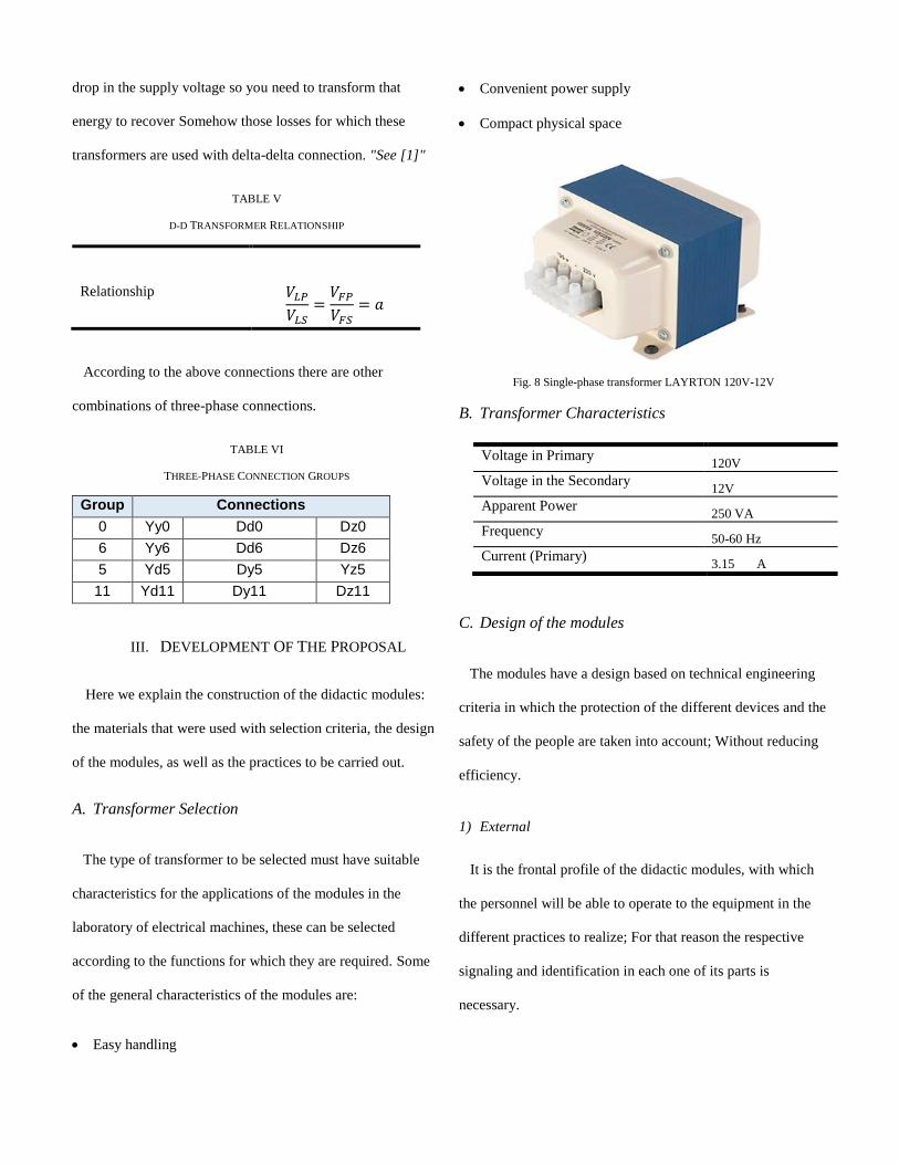
A. Transformer Selection
The type of transformer to be selected must have suitable
characteristics for the applications of the modules in the
laboratory of electrical machines, these can be selected
according to the functions for which they are required. Some
of the general characteristics of the modules are:
Easy handling
Convenient power supply
Compact physical space
Fig. 8 Single-phase transformer LAYRTON 120V-12V
B. Transformer Characteristics
C. Design of the modules
The modules have a design based on technical engineering
criteria in which the protection of the different devices and the
safety of the people are taken into account; Without reducing
efficiency.
1) External
It is the frontal profile of the didactic modules, with which
the personnel will be able to operate to the equipment in the
different practices to realize; For that reason the respective
signaling and identification in each one of its parts is
necessary.
Voltage in Primary 120V
Voltage in the Secondary 12V
Apparent Power 250 VA
Frequency 50-60 Hz
Current (Primary) 3.15 A

Fig. 9 Outside the module
On the outside is the configuration of the elements
connected internally:
• Primary windings
• Secondary windings
• Input voltage
• Output voltage
• "Banana Jack", to make various connections
• Three-phase supply "R, S, T"
• Its positive polarity
2) Internal part
It is the cover of the metal cabinet, which contains the
different work elements, assembled in the most convenient
way to save as much space as possible.
The ease of manipulation of the teaching modules is due to
the correct internal structure in both the connection points and
the wiring.
Fig. 10 Internal part of the module
D. Construction of the modules
The modules consist of local standardizations so that the
didactic module has an aesthetic presentation, according to
other existing boards in the Technical Education laboratory.
3) Construction of the cabinets
Fig. 11 Construction of the modules
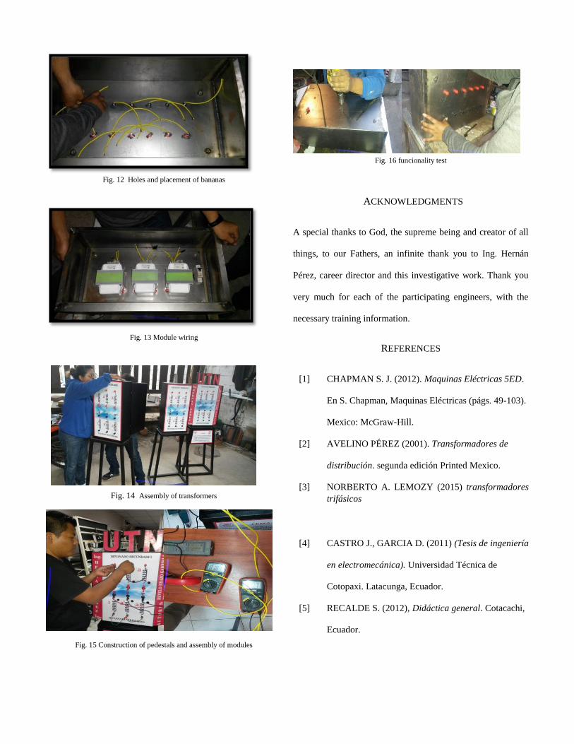
Fig. 12 Holes and placement of bananas
Fig. 13 Module wiring
Fig. 14 Assembly of transformers
Fig. 15 Construction of pedestals and assembly of modules
Fig. 16 funcionality test
ACKNOWLEDGMENTS
A special thanks to God, the supreme being and creator of all
things, to our Fathers, an infinite thank you to Ing. Hernán
Pérez, career director and this investigative work. Thank you
very much for each of the participating engineers, with the
necessary training information.
REFERENCES
[1] CHAPMAN S. J. (2012). Maquinas Eléctricas 5ED.
En S. Chapman, Maquinas Eléctricas (págs. 49-103).
Mexico: McGraw-Hill.
[2] AVELINO PÉREZ (2001). Transformadores de
distribución. segunda edición Printed Mexico.
[3] NORBERTO A. LEMOZY (2015) transformadores
trifásicos
[4] CASTRO J., GARCIA D. (2011) (Tesis de ingeniería
en electromecánica). Universidad Técnica de
Cotopaxi. Latacunga, Ecuador.
[5] RECALDE S. (2012), Didáctica general. Cotacachi,
Ecuador.

[6] YANES SALAZAR (2010). (Tesis de escuela de
formación tecnológica). Escuela Politécnica
Nacional. Quito. Ecuador.
[7] RODRÍGUEZ MIGUEL ÁNGEL. Transformadores
trifásicos. Universidad Nacional Del Santa.
Chimbote. Perú