design and control architecture of a 3d printed modular snake robot
TRANSCRIPT

Design and Control Architecture of a 3D PrintedModular Snake Robot
Ikram Hussain Mohammed, Nicolas Gallardo, Patrick Benavidez and Mo JamshidiDepartment of Electrical and Computer Engineering
The University of Texas at San AntonioOne UTSA Circle, San Antonio, TX 78249, USA
Email: [email protected], [email protected],[email protected], [email protected]
Benjamin ChampionSchool of Engineering
Deakin UniversityWaurn Ponds, VIC, AUS
Email: [email protected]
Abstract—In this paper the design and construction of a 3Dprinted snake robot is presented. This snake robot has beendesigned to be able to complete a wide variety of tasks andmotions that other snake robots are currently able to preform,such as serpentine motion, rolling and the ability to climb someobjects. An approach is also investigated which allows the snakerobot to be attached to the end of a serial manipulator robot toincrease its available degrees of freedom. A modular design hasbeen focused on, allowing for the fast and low cost generationand implementation of the robotic snake.
Index Terms—snake robot, modular robotics, robot, Dynamixelservos, 3D printing
I. INTRODUCTION
There are many different types of robots existing in theworld today. When robots that operate on the land are con-sidered, generally tracked or wheeled robots are used. Thereare many challenges that have arisen that these types of robotsare unsuitable for, such as the navigation of unstable terrainsuch as in a collapsed building or when navigating in tightspaces like the inside of a pipe. To overcome these challengessnake robots, a many degree of freedom modular robot, havebeen developed. These type of robots use their many internalDegrees of Freedom (DOF) to thread through tightly packspaces, allowing the robot to have access to locations wherepeople or machinery cannot [1]. These robots can coordinatetheir internal DOF to perform a variety of movements likecrawling, climbing and swimming, making it suitable fornumber of applications such as search and rescue in disastersite, inspection of narrow and unstructured environments likecollapsed buildings and even in reconnaissance situations [2],[3]. A snake robot can also be used as end effector of amanipulator to increase the number of DOF of the robot.
This paper presents a modular snake robot that combinesthe strengths of the current state of the art designs discussedin background section. This snake robot has been developed toachieve complicated tasks such as: climbing, smooth serpen-tine motion, and increase a ABB Industrial Manipulator robot’sDOF. The following paper is organized as follows: Section II
* This work was supported by Grant number FA8750-15-2-0116 from AirForce Research Laboratory and OSD through a contract with North CarolinaAgricultural and Technical State University.
presents the current research that is being conducted usingsnake robots. Section III details a design for a snake robotthat is able to achieve the proposed tasks. Section IV presentsthe control architecture of the snake robot. Details on howthe designed system has been tested is provided in section V.Finally, the paper is concluded and future work is presentedin Section VI.
II. BACKGROUND
Before the construction of the snake robot began, researchwas conducted into the various different forms of snakerobots that have currently been implemented refer [4]–[7].A description of the main variants of the snake robot are asfollows.
The first model of snake robot investigated was the CMUmodular snake robot. This type of snake robot is able tomove in a 3D manner, which allows it complete a widevariety of movements, such as climbing and linear progression,sidewinding, rolling, cornering and pipe rolling [8], whereits primary form of motion is the corkscrew motion. Thisrobot was designed with expandability in mind, as each ofthe segments that make up the snake robot being exactly thesame, with the exception of the head and tail of the robot.Each of these unique segments contain only a single DOF, butwhen combined give the robot n degrees of freedom, relativeto the length of the snake [8]. This snake robot was initiallyprototypes using a 3D printer, and is now constructed withaluminum and a rubber to provide grip and durability. Thissnake robot is powered and controlled via a tether [4], whichmakes it unable to navigate too far away from a base station.This tether could also potentially become entangled on variousobjects in the environment.
The next robot that was considered was the ACM-R5.This robot is the most advanced in the ACM snake robotfamily by Hirose and Yamada [3]. ACM-R5 is an amphibioussnake robot which has ability to move both on the land andin the water. This snake robot is composed of 9 ModularUniversal Units [5]. Each of these modules have two degreesof freedom with an on-board CPU and power unit. This robothas passive wheels attached which allows it to move quicklyon a smooth surface. It is waterproofed using O-rings and

other water proofing accessories so that it can move smoothlyin the water. It can perform different motions like serpentinelocomotion, concertina movement, sidewinding, S-shape andE-shape rolling, Arc-shape rolling and helical rolling but itsprimary motion is serpentine movement [5]. The disadvantageof this robot is it cannot climb.
Unlike the previous two snake robots considered, the nextsnake robot is of a different kind developed by OC robotics,the snake-arm robot [9]. This is a fixed robot, mainly beingused in manufacturing applications as well as being able tobe used in hazardous environments, such as a nuclear powerplant. This robot has a fixed base which accommodates allthe actuation and electronics required to move the robot. Itis driven by a wire rope and controlled via software to getto the desired positions. It is designed with a hollow core,so cabling, hoses and other equipment can be routed thoughthe center of arm. There are two types of snake-arm robotsavailable for these applications, the spatial snake-arm robotand planar snake arm robot. The first robot, the spatial snakearm robot, has a total of 12 links with two DOF each. Thisprovides a total of 24 DOF to the system. These robots aremounted on a linear axes from a fixed position, and is thendeployed into the environment. This allows the robot to havesturdy base in-which to operate from, but still allows motionin a single axis in conjunction with the arm itself. This robotcan also be utilized by mounting it to a mobile robot, or byattaching it to the end of a manipulator robot to increase theDOF of the robot. The second robot is planar snake robot.This robot only has the capacity to articulate itself in oneplane. This robot is very compact, as it is able to save spaceby coiling around an actuator pack.
After analyzing the aforementioned snake robots, thestrengths and weakness can be obtained. The CMU robot isvery versatile as it has the ability to move with most typesof snake movement, but it lacks the ability to traverse in thetraditional serpentine type movement. Conversely, the ACM-R5 robot is able to use this type of movement, but is able toclimb up different types of objects. The third type of robot, thesnake arm robot, does not use a modular design but is able toachieve a high DOF by utilizing a series of cables attached tomotors within its base. These strengths and weaknesses wereconsidered during the design phase of the presented robot.
III. DESIGN
Each module of the 3D printed modular snake robot func-tions as single rotational joint with one Degree of Freedom(DOF). Every module is able to rotate 90 degrees with respectto previous module, thus enabling the generation of movementutilizing many different methods. Each module is connectedto the previous module in such a way that the axis of rotationis perpendicular with respect to previous one. Having twodifferent axis of movement in each segment pair, means thatthe robot is able to generate movement in all three axis givenat least four segments in the chain. In other words, the modulesallow for movement in both the vertical and horizontal axis,thus enabling the robot to move in a three dimensional plane.
The current design consists of 16 modules including a headand tail module, which can be altered depending on theapplication. Having this many modules provides 16 DOF,which can be increased or decreased by simply adding orsubtracting the amount of conjoined modules. Each moduleis 2.15 inches (5.48 cm) in diameter, and has a length of 2.95inches (7.5 cm) in-between the joint axes.
Fig. 1. Components of 3D Printed modular snake robot
As shown in the figure 1 the module consists of a housing,a Dynamixel servo motor, a Lithium polymer(LiPo) batteryand an internal channel that allows the communication andpower cables to be passed down the chain. The housing isconstructed via 3D printing using PLA, a commonly usedbiodegradable 3D printing material, which contains all of thecomponents within the module. The Dynamixel motor pro-vides the torque and velocity required to provided movementto the next module. Every module has a single cell (1s) 3.7VLiPo battery inside of it, which is connected with two othermodules in series to make up the 11.1 volts required to powerthe segments. Because of this, pairs of three modules shouldalways be used. Each segment’s power is then connected inparallel to the rest of the snake. This will allow for any of themodules to always have enough current available to them toprovide the maximum torque possible to each of the motors.It will also ensure that each segment of the snake will alwaysbe powered while the other segments of the snake are able tooperate.
A. Housing
The housing consist of two parts, these being the fronthousing and rear housing. The front housing is the main part
of the module. This contains space to house both the batteryand the servo motor. To accommodate for the wires providingboth communication and power to the next module, parts ofthe wall of the module were thinned slightly. This was done ina circular pattern around the module, as opposed to only beendone in a single place, to reduce a weak-spot being made inthe housing wall. The rear housing acts as a cap to cover themodule. Figure 2, depicts the front and rear housing of therobot.
Fig. 2. Snake Robot Housing
To enable the many different types of movement presentwhen snake robots are considered, a cylindrical design forthe housing has been chosen. Having a cylindrical design isoptimal for both rolling and climbing activities. This housingis designed in such a way that any part of the robot will notexceed 2.16 inches (5.5cm) in diameter. As the center part ofthe body is cylindrical, it can accommodate the structure forthe passive wheel adapter, which can be attached and detacheddepending on the application. This passive wheel adapter willallow the robot to be able to easily preform the types ofmovement that a cylindrical body is not ideal for, such asthe serpentine type movement.
B. Passive Wheel Adapter
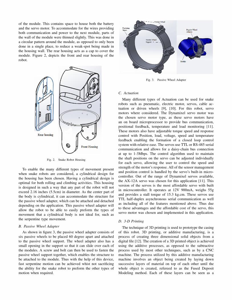
As shown in figure 3, the passive wheel adapter consists ofsix passive wheels to be placed 60 degree apart and attachedto the passive wheel support. The wheel adapter also has asmall opening in the support so that it can slide over each ofthe modules. A screw and bolt can then be used to fasten thepassive wheel support together, which enables the structure tobe attached to the module. Thus with the help of this device,fast serpentine motion can be achieved whist not sacrificingthe ability for the snake robot to preform the other types ofmotion when required.
Fig. 3. Passive Wheel Adapter
C. Actuation
Many different types of Actuation can be used for snakerobots such as pneumatic, electric motor, servos, cable ac-tuation or driven wheels [9], [10]. For this robot, servomotors where considered. The Dynamixel servo motor wasthe chosen servo motor type, as these servo motors havean on board microprocessor to provide bus communication,positional feedback, temperature and load monitoring [11].These motors also have adjustable torque speed and responsecontrol with Position, load, voltage, speed and temperaturefeedback enabling the formation of a closed loop controlsystem with relative ease. The servos use TTL or RS-485 serialcommunication and allows for a daisy-chain bus connectionat up to 1-3Mbps. The control algorithm used to maintainthe shaft positions on the servo can be adjusted individuallyfor each servo, allowing the user to control the speed andstrength of the motor’s response. All of the sensor managementand position control is handled by the servo’s built-in micro-controller. Out of the range of Dynamixel servos available,the AX-12A servo was chosen for this application [11]. Thisversion of the servos is the most affordable servo with builtin microcontroller. It operates at 12V 900mA, weighs 55gand provides a stall torque of 15.3 kg.cm. These servos useTTL half-duplex asynchronous serial communication as wellas including all of the features mentioned above. Thus dueto these advantages and the affordable cost of the servo, thisservo motor was chosen and implemented in this application.
D. 3-D Printing
The technique of 3D printing is used to prototype the casingof this robot. 3D printing, or additive manufacturing, is aprocess of creating three dimensional solid objects from adigital file [12]. The creation of a 3D printed object is achievedusing the additive processes, as opposed to the subtractiveprocess used by most other techniques, such as by a CNCmachine. The process utilized by this additive manufacturingmachine involves an object being created by laying downsuccessive layers of material on top of each other until thewhole object is created, refereed to as the Fused DepositModeling method. Each of these layers can be seen as a
thinly sliced horizontal cross-section of the eventual object[13]. The digital file of the object to be printed is made usinga 3D scanner, to copy an existing object, or in a ComputerAided Design (CAD) program for the creation of a totally newobject. After the model has been completed, the file can thenbe saved in a general file type, such as the STL format, whichis processed by software knows as a slicer. This softwareconverts the model into a series of thin layers and produces aG-code file containing instructions tailored to a specific typeof 3D printer which enables the printer to create the model.
3D printing helps in the fast prototyping process whichsaves time and money. This is a big advantage as if thesame parts were to be manufactured by hand it would take asignificant amount of time to complete, as well as being veryexpensive due to the labor and machine costs involved. While3D printing the first module, it was easy to find problems inthe design, rectify it and then print the design again. Becauseof this, the design of the module was able to be easily changedto accommodate for new communication and power lines.
Each module of the snake robot was printed on the LulzbotTaz 4 which is an open source 3D printer. It supports ma-terial such as PLA, ABS, HIPS, Ninja Flex etc. Amongthese materials, PLA (Poly-lactic Acid) was selected as itdemonstrates significantly less part warping, higher maximumprinting speeds, lower layer heights, sharper printed cornersand affordable pricing compared to some of the other options.The virtual design for printing the module is designed in CADsoftware, in this case using SolidWorks, and saved in the STLformat. This file is then opened in Cura LulzBot, which actsas the slicer and therefore converts the model into GCODE aswell as allowing the user to control the operation of the 3Dprinter.
Unfortunately there are some disadvantages when using3D printed parts of this nature, as they are generally not asstrong, or as durable, as parts that might be constructed usingother methods. Because of this, 3D printing is used for theprototyping stage of this robot. If this robot was to be taken toa potentially hazards environment, such as a collapsed buildingor a site where there might potentially be corrosive material,the casing for the modules would need to be produced usingeither more traditional methods with stronger metal materials,or be constructed using an industrial grade 3D printer.
E. Implementation
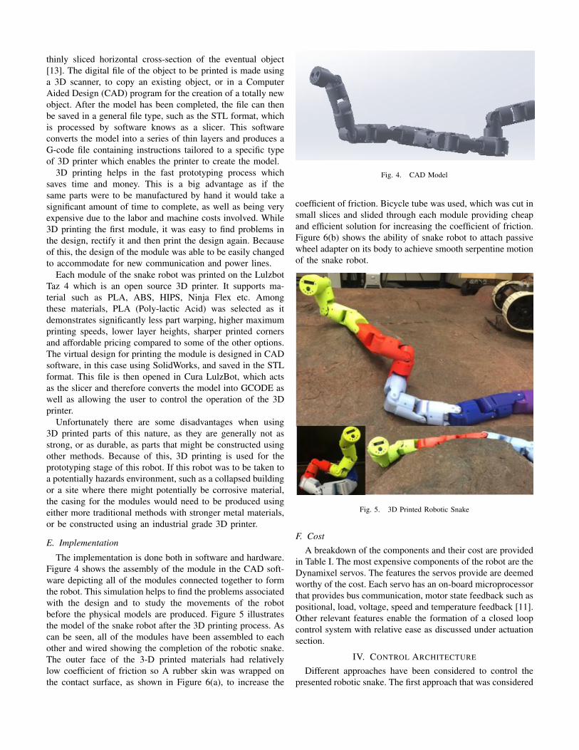
The implementation is done both in software and hardware.Figure 4 shows the assembly of the module in the CAD soft-ware depicting all of the modules connected together to formthe robot. This simulation helps to find the problems associatedwith the design and to study the movements of the robotbefore the physical models are produced. Figure 5 illustratesthe model of the snake robot after the 3D printing process. Ascan be seen, all of the modules have been assembled to eachother and wired showing the completion of the robotic snake.The outer face of the 3-D printed materials had relativelylow coefficient of friction so A rubber skin was wrapped onthe contact surface, as shown in Figure 6(a), to increase the
Fig. 4. CAD Model
coefficient of friction. Bicycle tube was used, which was cut insmall slices and slided through each module providing cheapand efficient solution for increasing the coefficient of friction.Figure 6(b) shows the ability of snake robot to attach passivewheel adapter on its body to achieve smooth serpentine motionof the snake robot.
Fig. 5. 3D Printed Robotic Snake
F. CostA breakdown of the components and their cost are provided
in Table I. The most expensive components of the robot are theDynamixel servos. The features the servos provide are deemedworthy of the cost. Each servo has an on-board microprocessorthat provides bus communication, motor state feedback such aspositional, load, voltage, speed and temperature feedback [11].Other relevant features enable the formation of a closed loopcontrol system with relative ease as discussed under actuationsection.
IV. CONTROL ARCHITECTURE
Different approaches have been considered to control thepresented robotic snake. The first approach that was considered
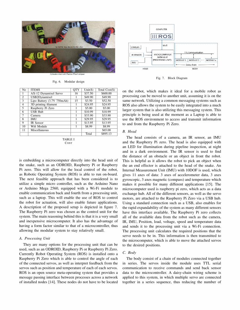
Fig. 6. Modular design
No ITEMS QTY Unit($) Total Cost($)1 AX-12 Dynamixel Servo 16 $37.50 $600.002 USB2Dynamixel 1 $49.90 $49.903 Lipo Battery (3.7V 750mAh) 15 $3.50 $52.504 3D printing filament 1 $24.95 $24.955 Raspberry Pi Zero 1 $5.00 $5.006 USB Hub 1 $10.99 $10.997 Camera 1 $33.90 $33.908 IMU 1 $29.95 $29.959 IR Sensor 1 $13.95 $13.9510 Wifi Module 1 $8.99 $8.9911 Miscellaneous $65.00
Total $895.13
TABLE ICOST
is embedding a microcomputer directly into the head unit ofthe snake, such as an ODROID, Raspberry Pi or RaspberryPi zero. This will allow for the local control of the robot,as Robotic Operating System (ROS) is able to run on-board.The next feasible approach that has been considered is toutilize a simple micro controller, such as the Arduino Nanoor Arduino Mega 2560, equipped with a Wi-Fi module toenable communication back and fourth from a processing unit,such as a laptop. This will enable the use of ROS to controlthe robot for actuation, will also enable future applications.A description of the proposed setup is depicted in figure 7.The Raspberry Pi zero was chosen as the control unit for thesystem. The main reasoning behind this is that it is a very smalland inexpensive microcomputer. It also has the advantage ofhaving a form factor similar to that of a microcontroller, thusallowing the modular system to stay relatively small.
A. Processing Unit
They are many options for the processing unit that can beused, such as an ODROID, Raspberry Pi or Raspberry Pi Zero.Currently Robot Operating System (ROS) is installed onto aRaspberry Pi Zero which is able to control the angle of eachof the connected servos, as well as interpret feedback from theservos such as position and temperature of each of each servos.ROS is an open source meta-operating system that provides amessage passing interface between processes across a networkof installed nodes [14]. These nodes do not have to be located
Fig. 7. Block Diagram
on the robot, which makes it ideal for a mobile robot asprocessing can be moved to another unit, assuming it is on thesame network. Utilizing a common messaging systems such asROS also allows the system to be easily integrated into a muchlarger system that is also utilizing this messaging system. Thisprinciple is being used at the moment as a Laptop is able touse the ROS environment to access and transmit informationto and from the Raspberry Pi Zero.
B. Head
The head consists of a camera, an IR sensor, an IMUand the Raspberry Pi zero. The head is also equipped withan LED for illumination during pipeline inspection, at nightand in a dark environment. The IR sensor is used to findthe distance of an obstacle or an object in front the robot.This is helpful as it allows the robot to pick an object whenthe an end effector is attached to the head of the snake. AnInternal Measurement Unit (IMU) with 10DOF is used, whichgives 11 axes of data: 3 axes of accelerometer data, 3 axesgyroscopic, 3 axes magnetic (compass) and temperature whichmakes it possible for many different applications [15]. Themicrocomputer used is raspberry pi zero, which acts as a dataexchange hub. All of the different sensors, as well as the servomotors, are attached to the Raspberry Pi Zero via a USB hub.Using a standard connection such as a USB, also enables forthe rapid expandability of the system as many different sensorshave this interface available. The Raspberry Pi zero collectsall of the available data from the robot such as the camera,IR, IMU, Position, load, voltage, speed and temperature dataand sends it to the processing unit via a Wi-Fi connection.The processing unit calculates the required positions that theservo needs to be in. This information is then transmitted tothe microcomputer, which is able to move the attached servosto the desired positions.
C. Body
The body consist of a chain of modules connected togetherin series. The servos inside the module uses TTL serialcommunication to receive commands and send back sensordata to the microcontroller. A daisy-chain wiring scheme isapplied to this system, in which multiple servo are connectedtogether in a series sequence, thus reducing the number of

wires required in the robot. This daisy-chain approach alsoallows for the system to be quickly scaled up or down asneeded.
V. TESTING AND APPLICATIONS
The system has been tested to generate different types of3D patterns by connecting the system directly to computervia a TTL to USB converter. A Dynamixel servo librarygenerated for ROS was used, with the help of a python scriptto implement square wave motion as shown in Figure 8 andthe pole climbing motion as shown in Figure 9 Implementationof other types of movement are still under development.
Fig. 8. Snake robot performing square wave motion
Fig. 9. Snake robot Climbing the pole
Another application that this system can be applied to isto be used as an end effector for a ABB robot as depictedin figure 10. If the robot that the snake is attached to alsofunctions via the ROS system, the two system can be easilyintegrated into one another.
Fig. 10. Snake robot used as End effector for an Industrial Robot
VI. CONCLUSIONS AND FUTURE WORKS
In this paper a design for a 3D printed modular snake robotwas presented which is low cost and was able to be constructedin a relatively short period of time. A control architecture forthe snake robot has also been presented focusing on using amicrocomputer to control the snake, with complex processingbeing undertaken outside the unit.
The implementation of all of the presented motions willbe undertaken in the future, with the complete integration ofthe snake robot into a serial manipulator robot, as well asthe robot to be integrated into a system of other robots to beinvestigated.
REFERENCES
[1] C. Wright, A. Johnson, A. Peck, Z. McCord, A. Naaktgeboren, P. Gi-anfortoni, M. Gonzalez-Rivero, R. Hatton, and H. Choset, “Design ofa modular snake robot,” in Intelligent Robots and Systems, 2007. IROS2007. IEEE/RSJ International Conference on. IEEE, 2007, pp. 2609–2614.
[2] A. Johnson, C. Wright, M. Tesch, K. Lipkin, and H. Choset, “A novelarchitecture for modular snake robots,” Citeseer, Tech. Rep., 2011.
[3] S. Hirose and H. Yamada, “Snake-like robots [tutorial],” Robotics &Automation Magazine, IEEE, vol. 16, no. 1, pp. 88–98, 2009.
[4] C. Wright, A. Buchan, B. Brown, J. Geist, M. Schwerin, D. Rollinson,M. Tesch, and H. Choset, “Design and architecture of the unifiedmodular snake robot,” in Robotics and Automation (ICRA), 2012 IEEEInternational Conference on. IEEE, 2012, pp. 4347–4354.
[5] S. Yu, S. Ma, B. Li, and Y. Wang, “An amphibious snake-like robot:Design and motion experiments on ground and in water,” in Informationand Automation, 2009. ICIA’09. International Conference on. IEEE,2009, pp. 500–505.
[6] A. Crespi and A. J. Ijspeert, “Amphibot ii: An amphibious snake robotthat crawls and swims using a central pattern generator,” in Proceedingsof the 9th international conference on climbing and walking robots(CLAWAR 2006), no. BIOROB-CONF-2006-001, 2006, pp. 19–27.
[7] T. Aoki, H. Ohno, and S. Hirose, “Design of slim slime robot ii (ssr-ii)with bridle bellows,” in Intelligent Robots and Systems, 2002. IEEE/RSJInternational Conference on, vol. 1. IEEE, 2002, pp. 835–840.
[8] Modular snake robots:gaits. [Online]. Available:http://biorobotics.ri.cmu.edu/projects/modsnake/newwebsite/gaits/
[9] Snake-arm robots. [Online]. Available:http://www.ocrobotics.com/technology-/snakearm-robots/
[10] K. J. Dowling, “Limbless locomotion: learning to crawl with a snakerobot,” Ph.D. dissertation, NASA, 1996.
[11] Dynamixel-ax-12a-servo. [Online]. Available:http://www.generationrobots.com/media/Dynamixel-AX-12-user-manual.lpdf
[12] 3d printing - wikipedia, the free encyclopedia. [Online]. Available:https://en.wikipedia.org/wiki/3D-printing
[13] What is 3d printing? how does 3d printing work? [Online]. Available:http://3dprinting.com/what-is-3d-printing/
[14] Robotic operating system. [Online]. Available:https://en.wikipedia.org/wiki/Robot Operating System
[15] Imu. [Online]. Available: https://www.adafruit.com/product/1604