design and control of a small-clearance driving simulator
TRANSCRIPT

HAL Id: hal-00342980https://hal.archives-ouvertes.fr/hal-00342980
Submitted on 28 Sep 2009
HAL is a multi-disciplinary open accessarchive for the deposit and dissemination of sci-entific research documents, whether they are pub-lished or not. The documents may come fromteaching and research institutions in France orabroad, or from public or private research centers.
L’archive ouverte pluridisciplinaire HAL, estdestinée au dépôt et à la diffusion de documentsscientifiques de niveau recherche, publiés ou non,émanant des établissements d’enseignement et derecherche français ou étrangers, des laboratoirespublics ou privés.
Design and Control of a Small-Clearance DrivingSimulator.
Lamri Nehaoua, Hakim Mohellebi, Ali Amouri, Hichem Arioui, StéphaneEspié, Abderrahmane Kheddar
To cite this version:Lamri Nehaoua, Hakim Mohellebi, Ali Amouri, Hichem Arioui, Stéphane Espié, et al.. Design andControl of a Small-Clearance Driving Simulator.. IEEE Transactions on Vehicular Technology, Insti-tute of Electrical and Electronics Engineers, 2008, 57 (2), pp.736–746. 10.1109/TVT.2007.905336.hal-00342980

IEEE TRANSACTIONS ON VEHICULAR TECHNOLOGY, VOL. X, NO. X, XXXXXX 2007 1
Design and Control of a Small-Clearance DrivingSimulator
Lamri Nehaoua, Hakim Mohellebi, Ali Amouri, Hichem Arioui, Stephane Espie,and Abderrahmane Kheddar,Member, IEEE,
Abstract— This paper presents a driving simulation which aimis twofold: (i) investigate the possibility to reduce motion clear-ance in order to achieve compact and low cost driving simulators,and (ii) evaluate multimodal and immersive virtual reality motionrestitution in platooning driving. The choice has been made for adriving simulator having at least two degrees of freedom. Theseconsist of the longitudinal displacement and seat rotations. Thesimulator is also equipped with force feedback steering wheelfor virtual drive assistance. These components are gathered ona serial kinematics type platform in order to facilitate controlscheme, and avoid the architecture complexity. A comparativestudy was made to devise a motion cueing strategy, takinginto account both psychophysical and technological constraints.Experimentations were carried out for several cases combinationsof longitudinal displacement and seat rotations.
Index Terms— Driving simulator, low clearance, motion cueing,psychophysics-based tuning
I. I NTRODUCTION
DRIVING simulators have become useful tools for cardesigning, training, and driver’s behavioral study. Their
utility has interested several universities and industrial labora-tories, for the development of new prototypes and validationof vehicle dynamic models. Nowadays, the important vehiclesnumber and subsequent road traffic became very problematicand expensive in human lives. The increasing statistics of roadaccidents urged several governmental institutions to encouragethe researchers in various fields of transport and vehiculardesign, to improve the road safety. Driving simulators makepossible a better understanding of the human’s behavior indrive situations close to reality.
Driving simulators became very accessible by technologicalheadway. Indeed, the calculators become more powerful andless expensive. Thus, several simulators1 of various architec-tures were built with an aim of either human factor study[1][2][3][4], or vehicle dynamic model validation, or testofnew car prototypes and functionalities [5][6][7].
Researches were led to show the nearly dominant role‘vection’ plays in human perception of motion [8]. Thesestudies were exploited to some extent by the so called fixed-base simulators. In this case, the driver controls a set of drivingcommands such acceleration/deceleration, braking, steering,
Manuscript received November 1, 2006; revised Xxxxxx 00, 2007. Thiswork was supported by the ANR in SIMACOM.
L. Nehaoua and S. Espie are with the INRETS–MSIS, Arcueil, FranceH. Mohellebi is with RENAULT, Saint Quentin-en-Yvelines, FranceA. Amouri, H. Arioui are with the IBISC–CNRS, Evry, FranceA. Kheddar is with the CNRS, Paris, France1From now on, simulator is meant to designate driving simulator.
while perceiving visual feedback of the current situation.Inorder to allow the operator’s virtual driving to be as closeas to that of a real situation, it would be necessary to equipthe simulator with equivalent multimodal cues (namely: visual,sound, haptic and inertial effects). Therefore, mobile platformswere combined with other displays to reproduce -in a reducedworkspace- in best the sensations perceived in the real case.This way makes it possible to improve both immersion qualityand simulation performances [9][10][11][12].
In such simulators, a large range of real-driving experi-enced accelerations cannot be reproduced. A compromise isto be found between the quality of various inertial indices’restitution and maintaining the platform within its reachableworkspace. Therefore, many control strategies were developed.They were firstly used for flight simulators motion cueing.Their porting to vehicle simulators is possible, but the vehicledynamics is of much higher frequencies (more abrupt andfrequent acceleration variation) than what is observed onairplanes. Besides, driving a vehicle takes place within trafficand unforeseen events (fog, pedestrians...) conditions whichcould create more complex scenarios.
Motion cueing algorithms are based on three main princi-ples. The first one consists in controlling the platform withinits physical limits, according to what need to be fed back fromthe simulation engine. The second principle, commonly calledwashout, brings back carefully the platform toward its neutralposition without causing sensory conflicts. Finally, the thirdprinciple, known as tilt-coordination, reproduces an illusorysustained accelerations by tilting with care the platform’s cabin(i.e. in a way the driver do not perceive the tilting).
Three classes of motion cueing strategies were developedand detailed in the literature: classical, optimal and adaptivealgorithms. The so called classical strategy, initially proposedby Schmidt and Conrad [13] to control the NASA’s flightsimulator, was implemented on the most of flight and drivingsimulators [14][15]. It consists in using a high-pass filter, to ex-tract the transient component of the longitudinal acceleration.Filtered acceleration is then integrated twice to determine theplatform desired displacement. Sustained longitudinal acceler-ation is extracted using a low-pass filter, and is reproducedbythe tilt-coordination principle. The resulting tilt angleis addedto that reproducing the angular velocities.
Adjustment of various algorithms requires psychophysicalknowledge, and depends on (i) the simulator architecture,(ii) the carried out maneuver, and (iii) the virtual environ-ment [16][17][18][19]. Hence, the classical approach, exceptits simplicity, suffers from some problems. It does not integrate
IEEE TRANSACTIONS ON VEHICULAR TECHNOLOGY, VOL. X, NO. X, XXXXXX 2007 2
explicitly a perception model, and filter parameters tuningisdone in the worst case (workspace is then not fully exploitedduring moderate acceleration or braking). To overcome theselimitations, an approach that borrows from optimal controltheory, including a perceptual model has been developed.Finally, an adaptive approach makes it possible to computethe filters’ parameters at each time step, according to inputacceleration or braking of the simulated vehicle.
In this paper, a low-cost motion platform having two degreesof freedom has been designed and built [20][21]. The choice ofthis architecture is motivated by two research investigations:how a low clearance can be coupled with rich complemen-tary multimodal cues to allow compact and fully functionaldriving simulator? Is the system useful for driver’s behaviorstudy in platooning driving contexts? In the next section,the mechatronic architecture of the mini simulator SIM2, andits modeling (longitudinal displacement and rotation of seat)are described. The third section justifies the choice of themotion cueing algorithm, which is assessed by qualitativeand quantitative comparisons. Finally, experimental results,psychophysical evaluations and conclusions are given.
II. PLATFORM CONCEPTION
A. Simulator architecture
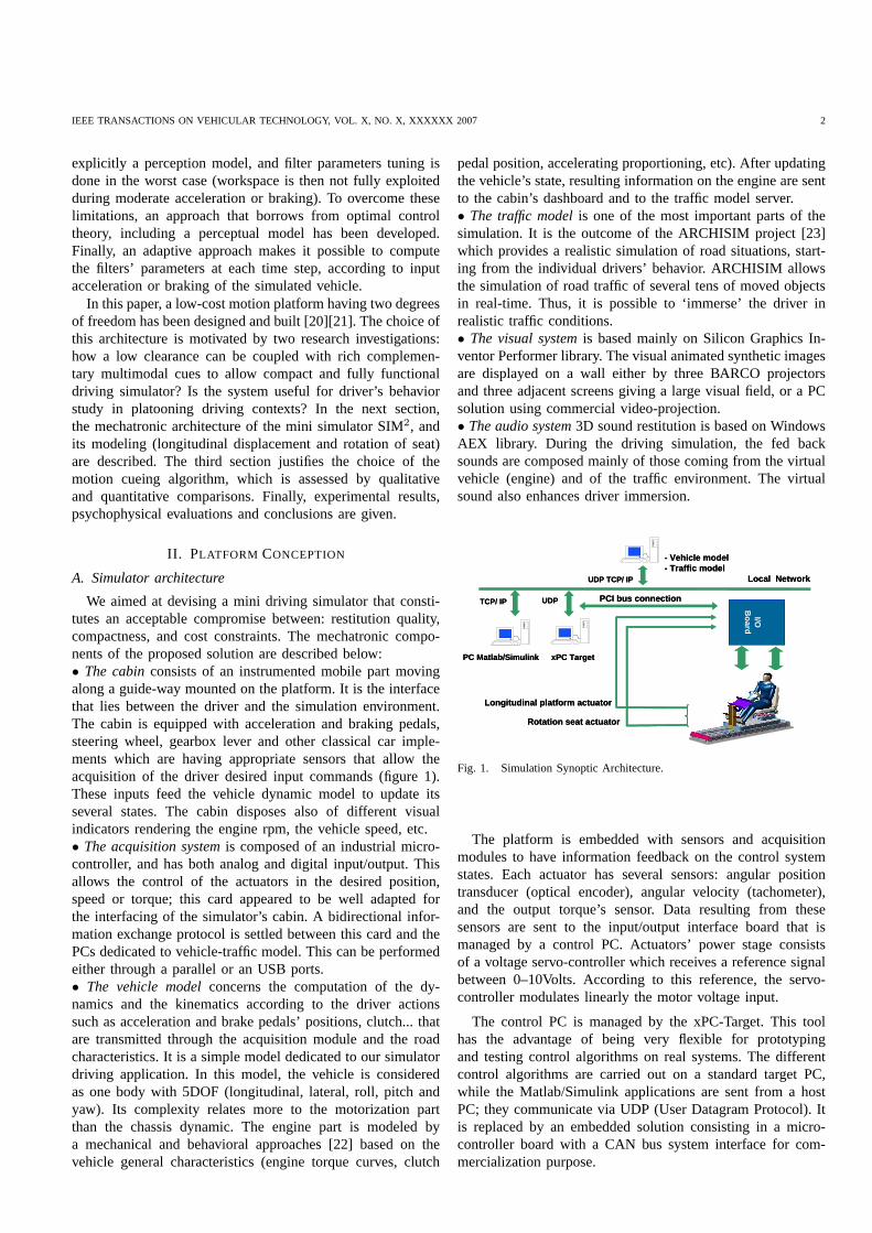
We aimed at devising a mini driving simulator that consti-tutes an acceptable compromise between: restitution quality,compactness, and cost constraints. The mechatronic compo-nents of the proposed solution are described below:• The cabinconsists of an instrumented mobile part movingalong a guide-way mounted on the platform. It is the interfacethat lies between the driver and the simulation environment.The cabin is equipped with acceleration and braking pedals,steering wheel, gearbox lever and other classical car imple-ments which are having appropriate sensors that allow theacquisition of the driver desired input commands (figure 1).These inputs feed the vehicle dynamic model to update itsseveral states. The cabin disposes also of different visualindicators rendering the engine rpm, the vehicle speed, etc.• The acquisition systemis composed of an industrial micro-controller, and has both analog and digital input/output. Thisallows the control of the actuators in the desired position,speed or torque; this card appeared to be well adapted forthe interfacing of the simulator’s cabin. A bidirectional infor-mation exchange protocol is settled between this card and thePCs dedicated to vehicle-traffic model. This can be performedeither through a parallel or an USB ports.• The vehicle modelconcerns the computation of the dy-namics and the kinematics according to the driver actionssuch as acceleration and brake pedals’ positions, clutch... thatare transmitted through the acquisition module and the roadcharacteristics. It is a simple model dedicated to our simulatordriving application. In this model, the vehicle is consideredas one body with 5DOF (longitudinal, lateral, roll, pitch andyaw). Its complexity relates more to the motorization partthan the chassis dynamic. The engine part is modeled bya mechanical and behavioral approaches [22] based on thevehicle general characteristics (engine torque curves, clutch
pedal position, accelerating proportioning, etc). After updatingthe vehicle’s state, resulting information on the engine are sentto the cabin’s dashboard and to the traffic model server.• The traffic modelis one of the most important parts of thesimulation. It is the outcome of the ARCHISIM project [23]which provides a realistic simulation of road situations, start-ing from the individual drivers’ behavior. ARCHISIM allowsthe simulation of road traffic of several tens of moved objectsin real-time. Thus, it is possible to ‘immerse’ the driver inrealistic traffic conditions.• The visual systemis based mainly on Silicon Graphics In-ventor Performer library. The visual animated synthetic imagesare displayed on a wall either by three BARCO projectorsand three adjacent screens giving a large visual field, or a PCsolution using commercial video-projection.• The audio system3D sound restitution is based on WindowsAEX library. During the driving simulation, the fed backsounds are composed mainly of those coming from the virtualvehicle (engine) and of the traffic environment. The virtualsound also enhances driver immersion.
Local Network
xPC TargetPC Matlab/Simulink
PCI bus connectionTCP/ IP UDP
- Vehicle model - Traffic model
UDP TCP/ IP
I/O
Board
Longitudinal platform actuator
Rotation seat actuator
Local Network
xPC TargetPC Matlab/Simulink
PCI bus connectionTCP/ IP UDP
- Vehicle model - Traffic model
UDP TCP/ IP
I/O
Board
Longitudinal platform actuator
Rotation seat actuator
Fig. 1. Simulation Synoptic Architecture.
The platform is embedded with sensors and acquisitionmodules to have information feedback on the control systemstates. Each actuator has several sensors: angular positiontransducer (optical encoder), angular velocity (tachometer),and the output torque’s sensor. Data resulting from thesesensors are sent to the input/output interface board that ismanaged by a control PC. Actuators’ power stage consistsof a voltage servo-controller which receives a reference signalbetween 0–10Volts. According to this reference, the servo-controller modulates linearly the motor voltage input.
The control PC is managed by the xPC-Target. This toolhas the advantage of being very flexible for prototypingand testing control algorithms on real systems. The differentcontrol algorithms are carried out on a standard target PC,while the Matlab/Simulink applications are sent from a hostPC; they communicate via UDP (User Datagram Protocol). Itis replaced by an embedded solution consisting in a micro-controller board with a CAN bus system interface for com-mercialization purpose.

IEEE TRANSACTIONS ON VEHICULAR TECHNOLOGY, VOL. X, NO. X, XXXXXX 2007 3
B. Platform description
Our aim is to devise a small clearance platform for motionrestitution and to search sufficient inertial effects that allowsa similar driving behavior in virtual reality. We designed andachieved a low cost mobile platform equipped with three de-grees of freedom (two of which are exclusive) and enough ini-tial clearances for preliminary investigations. The first mobilitytranslates the cabin front and rear longitudinal movement.Thesecond mobility consists of rotating lightly either the seat orthe seat’s back -manual switch-, independently from the first.
1) Longitudinal platform conception:The platform carriesboth the cabin of the mini-simulator and the driver. By meansof four sliders, assembled under the four ends of the cabin’sbase, the platform is able to move on a rail of 1.20m length.To this end, a Brushless type motor Parvex NX620 EAR isfixed at a mechanical stand related to the platform’s rails.The motor rotation is transformed into cabin’s longitudinalmotion through a ball-screw-nut system (see figure 2). Thisplatform achieves linear accelerations up to±0.66g in steadymode. At peak current, acceleration and speed of±1.32g and±3.95m/sec respectively are reached.
(1) Slide (2) Screw nut
(3) Rail
Brushless actuator and reductor
(5) screw
Fig. 2. Longitudinal platform mechanism.
2) Platform’s seat conception:The mechanism of the seatis designed in order to realize small rotations up to±10degof either the entire seat or only the seat’s back. These twoconfigurations are realized using a metal arm attached withthe seat’s back. This one comprises a groove in which a screwcan slide. A second mechanical element, fixed under the seat’sbase, comprises a groove in the same axis as that of the firstmetal arm. Consequently, the screw can slide through the twogrooves, either to fixes the metal arm at seat’s base, or todisassociates it; this is illustrated in figure 3 which allows oneto commute between the two configurations.
The different rotations are produced by a Brushless typemotor Parvex RX320 fixed below the seat. A transmissionsystem made up of a ball screw nut coupled to a pulley beltsystem transforms the rotational movement of the motor intotranslation of the nut fixed on a metal arm. This one beingattached to the seat, it engenders finally a rotational motion ofthe seat and/or seat’s back. In order to prevent the driving-shaftfrom deforming due to radial efforts, the motor frame can turnaround an axis to realign the two axes of the nut and the screw.
Seat’s rotation axis
2nd metallic arm
DC actuator
Seat’s rotation axis
2nd metallic arm
DC actuator
Rotation motion configuration
metallic arm for rotation motion selector
Seat’s rotation centre Screw
Screw/nut
Rotation motion configuration
metallic arm for rotation motion selector
Seat’s rotation centre Screw
Screw/nut
Fig. 3. Under seat’s mechanics.
This system reproduces a linear acceleration of±0.127g at thedriver vestibule. At peak current, a vestibule linear accelerationup to ±0.662g is reached (the average distance between theseat’s rotation axis and the driver’s vestibule is≈ 0.95m).
C. Haptic feedback steering wheel
To give an actual vehicle a desired course, the driver exertsefforts on the steering wheel. Efforts due to the tire/roadcontact and vehicle dynamics are also transmitted to thesteering wheel through the steering column linkages. Thisperceived feedback is is necessary to orient well the vehicleand to feel the limits of its adherence. To allow haptic feedbackwe motorized the steering wheel of the cabin and developedour own algorithm inspired from teleoperation technology.Indeed the energy which flows between the driver and thevehicle front wheels through the mechanical linkage can beconsidered to be mainly effort and flow exchange corre-sponding to force and velocity [24]. Therefore, the cabin’ssteering system is modeled based on the principle of linear
IEEE TRANSACTIONS ON VEHICULAR TECHNOLOGY, VOL. X, NO. X, XXXXXX 2007 4
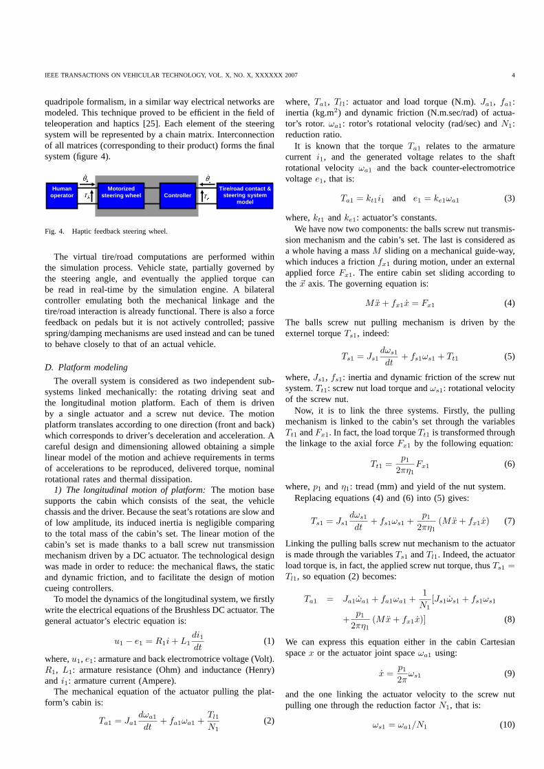
quadripole formalism, in a similar way electrical networksaremodeled. This technique proved to be efficient in the field ofteleoperation and haptics [25]. Each element of the steeringsystem will be represented by a chain matrix. Interconnectionof all matrices (corresponding to their product) forms the finalsystem (figure 4).
Human operator
Motorized steering wheel
Controller
Tire /road contact & steering system
model
θɺ θɺ τ τ
Fig. 4. Haptic feedback steering wheel.
The virtual tire/road computations are performed withinthe simulation process. Vehicle state, partially governedbythe steering angle, and eventually the applied torque canbe read in real-time by the simulation engine. A bilateralcontroller emulating both the mechanical linkage and thetire/road interaction is already functional. There is alsoa forcefeedback on pedals but it is not actively controlled; passivespring/damping mechanisms are used instead and can be tunedto behave closely to that of an actual vehicle.
D. Platform modeling
The overall system is considered as two independent sub-systems linked mechanically: the rotating driving seat andthe longitudinal motion platform. Each of them is drivenby a single actuator and a screw nut device. The motionplatform translates according to one direction (front and back)which corresponds to driver’s deceleration and acceleration. Acareful design and dimensioning allowed obtaining a simplelinear model of the motion and achieve requirements in termsof accelerations to be reproduced, delivered torque, nominalrotational rates and thermal dissipation.
1) The longitudinal motion of platform:The motion basesupports the cabin which consists of the seat, the vehiclechassis and the driver. Because the seat’s rotations are slow andof low amplitude, its induced inertia is negligible comparingto the total mass of the cabin’s set. The linear motion of thecabin’s set is made thanks to a ball screw nut transmissionmechanism driven by a DC actuator. The technological designwas made in order to reduce: the mechanical flaws, the staticand dynamic friction, and to facilitate the design of motioncueing controllers.
To model the dynamics of the longitudinal system, we firstlywrite the electrical equations of the Brushless DC actuator. Thegeneral actuator’s electric equation is:
u1 − e1 = R1i + L1
di1
dt(1)
where,u1, e1: armature and back electromotrice voltage (Volt).R1, L1: armature resistance (Ohm) and inductance (Henry)and i1: armature current (Ampere).
The mechanical equation of the actuator pulling the plat-form’s cabin is:
Ta1 = Ja1
dωa1
dt+ fa1ωa1 +
Tl1
N1
(2)
where, Ta1, Tl1: actuator and load torque (N.m).Ja1, fa1:inertia (kg.m2) and dynamic friction (N.m.sec/rad) of actua-tor’s rotor. ωa1: rotor’s rotational velocity (rad/sec) andN1:reduction ratio.
It is known that the torqueTa1 relates to the armaturecurrent i1, and the generated voltage relates to the shaftrotational velocityωa1 and the back counter-electromotricevoltagee1, that is:
Ta1 = kt1i1 and e1 = ke1ωa1 (3)
where,kt1 andke1: actuator’s constants.We have now two components: the balls screw nut transmis-
sion mechanism and the cabin’s set. The last is considered asa whole having a massM sliding on a mechanical guide-way,which induces a frictionfx1 during motion, under an externalapplied forceFx1. The entire cabin set sliding according tothe ~x axis. The governing equation is:
Mx + fx1x = Fx1 (4)
The balls screw nut pulling mechanism is driven by theexternel torqueTs1, indeed:
Ts1 = Js1
dωs1
dt+ fs1ωs1 + Tt1 (5)
where,Js1, fs1: inertia and dynamic friction of the screw nutsystem.Tt1: screw nut load torque andωs1: rotational velocityof the screw nut.
Now, it is to link the three systems. Firstly, the pullingmechanism is linked to the cabin’s set through the variablesTt1 andFx1. In fact, the load torqueTt1 is transformed throughthe linkage to the axial forceFx1 by the following equation:
Tt1 =p1
2πη1
Fx1 (6)
where,p1 andη1: tread (mm) and yield of the nut system.Replacing equations (4) and (6) into (5) gives:
Ts1 = Js1
dωs1
dt+ fs1ωs1 +
p1
2πη1
(Mx + fx1x) (7)
Linking the pulling balls screw nut mechanism to the actuatoris made through the variablesTs1 andTl1. Indeed, the actuatorload torque is, in fact, the applied screw nut torque, thusTs1 =Tl1, so equation (2) becomes:
Ta1 = Ja1ωa1 + fa1ωa1 +1
N1
[Js1ωs1 + fs1ωs1
+p1
2πη1
(Mx + fx1x)] (8)
We can express this equation either in the cabin Cartesianspacex or the actuator joint spaceωa1 using:
x =p1
2πωs1 (9)
and the one linking the actuator velocity to the screw nutpulling one through the reduction factorN1, that is:
ωs1 = ωa1/N1 (10)

IEEE TRANSACTIONS ON VEHICULAR TECHNOLOGY, VOL. X, NO. X, XXXXXX 2007 5
Finally, replacing and rearranging the previous equations:
kt1i1 =
(2πN1
p1
Ja1 +2π
p1N1
Js1 +p1
2πη1N1
M
)
︸ ︷︷ ︸
J1
x +
(2πN1
p1
fa1 +2π
p1N1
fs1 +p1
2πη1N1
fx1
)
︸ ︷︷ ︸
f1
x (11)
Since:
u1 = R1i1 + L1
di1
dt+
2πN1ke1
p1
x (12)
and using the well known Laplace transform, we can obtainthe transfer function between the cabin’s positionX (s) andthe voltage command signalU1 (s) as:
X
U1
=1
s
kt1[
(J1s + f1) (L1s + R1) + 2πN1
p1
ke1kt1
] (13)
2) The rotating seat model:As stated previously, the driverseat can perform two kinds of small rotational motions: therotation of only the seat’s back or the rotation of the entireseat. This is achieved by a single actuator thanks to a manualswitch. This motion can be coupled to the linear one givingfive possible combinations for experimental investigations ofmotion cueing strategies:
• linear motion of the platform coupled to the entire seatrotation;
• linear motion of the platform coupled the only seat back’srotation;
• the platform linear motion alone;• the entire seat’s rotation alone;• the entire seat back’s rotation alone.
The seat system can be split into three sub-systems: theactuator set, the balls screw nut transmission mechanism,and the seat (including the driver). At the actuator level,the electric and mechanics equations are the same, and thedifferent parameters are taken according to the new actuatorand reduction factor. The balls screw nut pulling system is alsosimilarly modeled. The load torque at the screw nut interactionlevel Tt2 generates an axial forceFt2:
Tt2 =p2
2πη2
Ft2 (14)
The seat system parameters are variable because of driver’svariability. Subsequently, it is difficult to determine thegravitycenter and the inertia parameters accurately. Nevertheless, weconsider that the gravity center is located at a pointG at adistanceρ from the rotation axis~y of the seat. The balls screwnut axis is located at a distancel from the axis~y. Then, theapplied forces at the seat (or seat’s back) are the gravity forceand the traction forceFt2 of the screw nut.
First, we must compute the momentum of the sys-tem with respect to the rotation center of the seat.For this, we define two frame reference axes: the abso-lute referenceℜ0 (O0, ~x0, ~y0, ~z0) and the relative referenceℜ1 (O1, ~x1, ~y1, ~z1) related to the rotation center of the seat,
O0
y0
z0
x0
O ρ ρ ρ ρ
φφφφθθθθ
x1
y1
z1
G
l
O0
y0
z0
x0
O ρ ρ ρ ρ
φφφφθθθθ
x1
y1
z1
G
l
Fig. 5. Seat axis space and geometrical parameters.
as shown in figure 5. The dynamic momentum of the systemseat-driver with respect toℜ1 is:
~δ (O1) = ~δ (G) + mt~γ (G) ×−−→GO1 (15)
where,mt: the whole seat and driver mass and~γ (G): accel-eration of the gravity center expressed as:
~γ (G) =d2−−−→O0O1
dt2+
d~ω
dt×−−→
O1G + ~ω ×(
~ω ×−−→O1G
)
(16)
where,~ω = θ~y1: is the seat rotation velocity. After rearrangingthe previous equations, we have:
~γ (G) =
x + θρ cos (θ + ϕ) − θ2ρ sin (θ + ϕ)0
−θρ sin (θ + ϕ) − θ2ρ cos (θ + ϕ)
(17)
then, by neglecting the second order termθ2:
~δ (O1) =(
Jt2θ + mt
(
xρ cos (θ + φ) + θρ2
))
~y1 (18)
where,Jt2: the whole seat and driver mass,ϕ: angle betweenthe lineO1G joining the gravity centerG and the origin of therelative referenceO1 and thez1 axis of the relative referenceℜ1 at the begining of the simulation.
Applying classical fundamental dynamics law to the seatsystem:
mtgρ sin (θ + φ) + Ft2l = Jt2θ + mt
(
xρ cos (θ + φ) + θρ2
)
(19)where,g: gravity vector.
Since the screw speed is related to the induced linear motionby ωs2 = 2π
p2
x, andx = lθ, then:
ωs2 =2π
p2
lθ (20)
Now, replacing each item, in a way similar to the motionplatform modeling gives:
kt2i2 = J2θ + f2θ − p2
2πη2lN2
mtf (x, θ) (21)

IEEE TRANSACTIONS ON VEHICULAR TECHNOLOGY, VOL. X, NO. X, XXXXXX 2007 6
where:
f (x, θ) = xρ cos (θ + φ) − gρ sin (θ + φ)
J2 =(
2πlN2
p2
Ja2 + 2πlp2N2
Js2 + p2
2πη2lN2
(Jt + mtρ
2))
f2 =(
2πlN2
p2
fa2 + 2πlp2N2
fs2
)
(22)
III. M OTION RESTITUTION
Obviously, the physical limits of the platform do not allowreproducing the full range of the inertial effects (accelerations).Moreover, we even seek to lower at maximum the longitudinalclearance of the platform. Thus, a cueing algorithm is neces-sary to generate platform trajectories which remain insidethereachable workspace while reproducing a driving behavior asclose as to that of a real situation.
In this section we investigate three cueing algorithms (clas-sical, optimal and adaptive) which are implemented and testedon the current simulator’s platform. The goal here is toevaluate the different motion cueing algorithms and to choosethe appropriate one for this driving simulator.
A. Classical Algorithm
High -pass
filter ∫∫
low -pass filter
High -pass filter
Real vehicle
linear Accelerations Platform
displacement
Real vehicle angular
velocities Platform rotations
Tilt & rate limit
∫
Washout High-pass
filter
Xɺɺ X Xɺɺ
ω β
β
β
Fig. 6. Motion cueing algorithm principle.
This algorithm consists of high-pass filtering the longi-tudinal acceleration resulting from vehicle dynamic modelto extract its transient component. Filtered accelerationisintegrated twice to have the desired platform’s position. Alow-pass filter extracts the sustained component of the accelerationused for tilt-coordination which uses gravity as an illusorysustained acceleration (figure 6). The Washout -consists inbringing back the platform to its neutral position- and tilt-coordination must be acheived with motions below the driver’sperceivable threshold. Therefore, a precise comprehension onthe vestibular system is required [26][27][28].
The filter order to be used is of importance because ahigh-pass filter should be at least of second order to limitthe acceleration reference, and of third order to carry outa Washout. Generally, due to various model imperfections,the filters’ parameters are tuned by a try-error heuristics.Wepropose a method which limits the interval of the parameterstobe chosen (cut-off frequency, damping and static gain), while
taking into account the perception (thresholds) and actuatorstechnology constraints (namely: time response and frictionof actuators, absolute and relative maximum displacementallowed by the platform in response to a simulated accelerationover a timetmax).
We consider that the output of the Washout filter is the pulseresponse of a second order low-pass filter as follows [29]:
Xp (s)
Xtr (s)=
K
s2 + 2ζωns + ω2n
(23)
where,Xp (s) : platform position,Xtr (s): transitory acceler-ation ζ: damping coefficient,ωn : filter natural pulsation andK : static gain. The pulse response of this filter for a dampingratio ζ > 1 is given by:
h (t) =K
τ1 − τ2
[
exp
(
− t
τ1
)
− exp
(
− t
τ2
)]
(24)
where,
τ1,2 = ζωn
±√
ζ2−1
ωn
(25)
Position
Velovity
Acceleration
Xpmax
dd_Xpmax
d_Xpmax
t
Pmax
as
vs
Position
Velovity
Acceleration
Xpmax
dd_Xpmax
d_Xpmax
t
Pmax
as
vs
Fig. 7. Maximum position.
The choice of an over-damping coefficient (ζ > 1) ismade in order to eliminate false cues. From this equation,and its first, second and third derivatives, we deduce themaximum platform displacement, velocity and accelerationresponse values for a given transient acceleration input, indeed:
|Xp max| = |K|ωnξ < Pmax (26)
Xp max = Kω2
nξ2 < vs (27)
Xp max = Kω3
nξ3 < as (28)
where,
ξ = exp
[
ζ√
ζ2 − 1ln
(
ζ −√
ζ2 − 1)]
(29)

IEEE TRANSACTIONS ON VEHICULAR TECHNOLOGY, VOL. X, NO. X, XXXXXX 2007 7
1 2 3 4 5 6 7 8 9 100
5
10
15
ζ
ωn
(rd/
s)
position constraint
velocity constraint
acceleration constraint
technologic constraint
Fig. 8. Acceptable parametersζ andωn.
and Pmax is the maximum allowed platform displacement(Pmin = −Pmax), vs andas are the velocity and the accelera-tion thresholds of the vestibular system respectively (figure 7).
The technological constraint relates to friction, and con-sequently, its direct dependence of the actuator parametersand the Washout filter (these two blocks are assembled incascade). Precisely, to benefit of the maximum of the actuator’scharacteristics (synthesized during initial dimensioning), theWashout filter must be selected in a manner to minimize thetotal friction. Therefore, a sufficient condition:
2ζωn < f0 (30)
where, f0: is the proper friction of actuation system, canachieve the matter. If this condition is not satisfied, thesimulation depends only on the actuator’s parameters, andconsequently, the adjustment of the motion cueing algorithmwould be reduced even eliminated. Shaded region in figure 8presents the acceptable high-pass filter parameters(ωn, ζ)which respect the constraints mentioned above.
B. Optimal algorithm
Initially proposed by Sivan et al. [30], it has been developedby Telban and Cardullo [31][32] to target an implementationon UTAIS flight simulator UTAIS. This algorithm uses filtersof higher order with an optimization method borrowed fromoptimal control theory.
The distinguishing feature is in incorporating a mathemat-ical model of the human vestibular system [33][34], in orderto reduce the error between the vestibular system’s output ofthe driver on the simulated vehicle and its counterpart comingfrom the driver on the driver simulator (figure 9).
The aim of this algorithm is to calculate a transfer functionW (s) which expresses the dynamic states of the simulatorus
u e u
Driver on simulator
Driver on simulated vehicle
Vestibular system
Vestibular system
Platform dynamics ( )W s
+ -
Fig. 9. Optimal Washout scheme.
with respect to those of the simulated vehicleuv
Us (s) = W (s) Uv (s) (31)
The optimal strategy determines the simulator acceleration us
by minimizing a cost function of the form:
J (us) = E
∞∫
0
(eT Qe + xT
d Rdxd + uTs Rus
)dt
(32)
where,e is supposed to be the sensory error,xd is the statevector containing the platform’s position and velocity,us isthe platform’s longitudinal acceleration.Q, Rd and R areweighting positive definite matrices; they define the compro-mise between the sensory error minimization and platform’sphysical constraints. Considering the small workspace ofthe platform and for security reasons, we have opted forrestrictive position cost function. Figures 10, 11 and 12 showthe comparison between optimal and classical algorithms for asquare longitudinal acceleration; both cases with and withoutplatform tilt-coordination.
C. Adaptive Algorithm
Firstly proposed by Parrish et al. [35] to provide motion cuesfor the Langley flight simulator. This algorithm can be seen asa classical one where parameters are variable and computed ateach time step of simulation. Several variants were proposedto improve the stability of the algorithm [36], e.g. by includingthe vestibular model for the lateral false cues reduction [37].
It is based on the minimization of a cost function containingthe acceleration error and constraints on the platform displace-ment. The adaptation is carried out using the steepest descentmethod to resolve the sensitivity equations. The resultingfilteris then nonlinear (figure 13).
The filter equation is given by:
xs = Kxv − 2ζωnxs − ω2
nxs (33)
where, xv is the simulated vehicle acceleration,xs,xs, andxs are the acceleration, the velocity and the position of theplatform respectively.K, ζ, ωn are the adapted Washout filterparameters. The cost functionJ to be minimized is:
1
2
[
wa (xv − xs)2
+ wvx2
s + wvx2
s + wK (K − K0)2
+
wζ (ζ − ζ0)2
+ wωn(ωn − ωn0)
2]
(34)

IEEE TRANSACTIONS ON VEHICULAR TECHNOLOGY, VOL. X, NO. X, XXXXXX 2007 8
0 2 4 6 8 10−0.2
0
0.2
0.4
0.6
0.8
time (s)
otol
ith r
espo
nse
(m/s
2 )
vehoptclas
0 2 4 6 8 10
−0.2
0
0.2
0.4
0.6
0.8
1
time (s)
spec
ific
forc
e (m
/s2 )
vehoptclas
Fig. 10. Otolith and specific force response comparison between optimaland classical algorithms with the platform tilt-coordination.
0 2 4 6 8 10−0.2
−0.15
−0.1
−0.05
0
0.05
0.1
0.15
time (sec)
SC
C r
espo
nse
OptclasSCC thresholdSCC threshold
Fig. 11. Semi-Circular Channels response comparison according to the tilt-coordination angular rate using optimal and classic algorithms.
Using the gradient descent optimization method [38]:
K = −γK
∂J
∂K(35)
ζ = −γζ
∂J
∂ζ(36)
ωn = −γωn
∂J
∂ω(37)
0 2 4 6 8 10
−0.2
0
0.2
0.4
0.6
0.8
1
time (s)
otol
ith r
espo
nse
(m/s
2 )
vehoptdata3
0 2 4 6 8 10
−1
−0.8
−0.6
−0.4
−0.2
0
0.2
0.4
0.6
0.8
1
time (t)
long
itudi
nal a
ccel
erat
ion
(m/s
2 )
vehoptclas
Fig. 12. Otolith and specific force response comparison between optimaland classical algorithms with only the longitudinal platform motion.
1s
Longitudinal acceleration
Platform displacement
Cost function Minimization
1s
Resolution of the sensitivity equations
High -pass filter
Adapted Parameters
adaptés
, , K ζ ω
Fig. 13. Adaptive Washout algorithm.
Once the weighting coefficientswi of the cost function and theinitial conditionsK0, ζ0 andωn0 are determined, the resolu-tion of the sensitivity equations allows to have the accelerationand position signals to drive the platform. Figure 14 shows thecomparison between adaptive and classical algorithms for asquare longitudinal acceleration, in both case with and withoutplatform tilt-coordination.
IEEE TRANSACTIONS ON VEHICULAR TECHNOLOGY, VOL. X, NO. X, XXXXXX 2007 9
0 2 4 6 8 10−0.2
0
0.2
0.4
0.6
0.8
1
1.2
time (s)
spec
ific
forc
e (m
/s2 )
vehadaptclas
0 2 4 6 8 10
−1
−0.8
−0.6
−0.4
−0.2
0
0.2
0.4
0.6
0.8
1
time (s)
long
itudi
nal a
ccel
erat
ion
(m/s
2 )
vehadaptclas
Fig. 14. Adaptive and classical Washout response comparisonwith (up) andwithout (down) tilt-coordination.
0 2 4 6 8 10−0.2
−0.15
−0.1
−0.05
0
0.05
0.1
0.15
time (sec)
SC
C r
epon
se
adaptclasSCC thresholdSCC threshold
Fig. 15. Semi-Circular Channels response comparison according to the tilt-coordination angular rate using adaptive and classic algorithms.
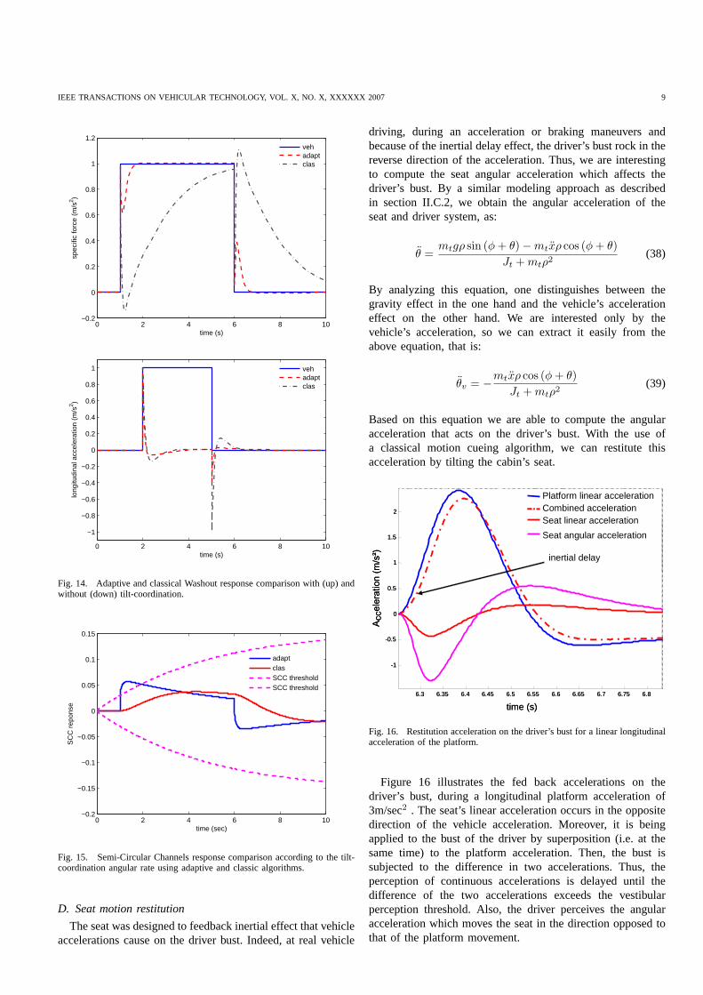
D. Seat motion restitution
The seat was designed to feedback inertial effect that vehicleaccelerations cause on the driver bust. Indeed, at real vehicle
driving, during an acceleration or braking maneuvers andbecause of the inertial delay effect, the driver’s bust rockin thereverse direction of the acceleration. Thus, we are interestingto compute the seat angular acceleration which affects thedriver’s bust. By a similar modeling approach as describedin section II.C.2, we obtain the angular acceleration of theseat and driver system, as:
θ =mtgρ sin (φ + θ) − mtxρ cos (φ + θ)
Jt + mtρ2(38)
By analyzing this equation, one distinguishes between thegravity effect in the one hand and the vehicle’s accelerationeffect on the other hand. We are interested only by thevehicle’s acceleration, so we can extract it easily from theabove equation, that is:
θv = −mtxρ cos (φ + θ)
Jt + mtρ2(39)
Based on this equation we are able to compute the angularacceleration that acts on the driver’s bust. With the use ofa classical motion cueing algorithm, we can restitute thisacceleration by tilting the cabin’s seat.
6.3 6.35 6.4 6.45 6.5 6.55 6.6 6.65 6.7 6.75 6.8
-1
-0.5
0
0.5
1
1.5
2
time (s)
Acce
lerati
on (m
/s²)
Platform linear accelerationCombined accelerationSeat linear acceleration
Seat angular acceleration
inertial delay
6.3 6.35 6.4 6.45 6.5 6.55 6.6 6.65 6.7 6.75 6.8
-1
-0.5
0
0.5
1
1.5
2
time (s)
Acce
lerati
on (m
/s²)
Platform linear accelerationCombined accelerationSeat linear acceleration
Seat angular acceleration
inertial delay
Fig. 16. Restitution acceleration on the driver’s bust for alinear longitudinalacceleration of the platform.
Figure 16 illustrates the fed back accelerations on thedriver’s bust, during a longitudinal platform acceleration of3m/sec2 . The seat’s linear acceleration occurs in the oppositedirection of the vehicle acceleration. Moreover, it is beingapplied to the bust of the driver by superposition (i.e. at thesame time) to the platform acceleration. Then, the bust issubjected to the difference in two accelerations. Thus, theperception of continuous accelerations is delayed until thedifference of the two accelerations exceeds the vestibularperception threshold. Also, the driver perceives the angularacceleration which moves the seat in the direction opposed tothat of the platform movement.

IEEE TRANSACTIONS ON VEHICULAR TECHNOLOGY, VOL. X, NO. X, XXXXXX 2007 10
IV. EXPERIMENTAL RESULTS
A. Motion cueing algorithms
In order to compare the performances of previous describedalgorithms, experimentations were carried out on the presenteddriving simulator (figure 17).
Fig. 17. INRETS/IBISC SIM2 mini driving simulator: the complete actualset-up in action.
Firstly, a scenario consisting in a set of accelerations, decel-erations and braking maneuvers is accomplished (the signalsare real ones, given by a car company). The resulting signalsfrom the vehicle dynamic model is saved to be executed onthe simulator for classical, adaptive and optimal algorithms.This is done to compare the different algorithms for the samemaneuver. Parameters of each algorithm are adjusted to respectthe physical constraints of the platform (±0.6m) [39]. Theplatform’s longitudinal acceleration and position are saved andplotted using Matlab/Simulink software to be analyzed.
0 5 10 15 20−4
−3
−2
−1
0
1
2
3
4
5
6
time (s)
acce
lera
tion
(m/s
2 )
vehicleadaptiveclassic
Fig. 18. Acceleration response comparison according to classical andadaptive algorithm.s
In absence of tilt-coordination, as the case of our platform,the classical and the adaptive algorithm show close perfor-mances. The restituted acceleration is better with a classical
0 5 10 15 20−4
−2
0
2
4
6
8
time (s)
acce
lera
tion
(m/s
2 )
vehicleoptimalclassic
Fig. 19. Acceleration response comparison according to classical and optimalalgorithms.
0 5 10 15 20−2.5
−2
−1.5
−1
−0.5
0
0.5
1
1.5
2
2.5
time (s)
otol
ith s
peci
fic fo
rce
(m/s
2 )
optimalvehicleclassic
Fig. 20. Otolith specific force response comparison according to classicaland optimal algorithms.
algorithm especially for acceleration phases, except that, withan adaptive gain, some false cues generated by the linearpropriety of the high-pass filters are reduced (figure 18). Inaddition, Figure 21 shows that the Washout is few morequick with a classical algorithm than the adaptive one, and noconsiderable improvement in the platform workspace is done.Therefore, we can deduce that with just a longitudinal motion,even with an adaptive gain the classical algortihm presentsaminor better performance comparing to the adaptive, with theadvantage of a simple parameters tuning.
Optimal algorithm provides a better acceleration cueing, es-pecially for onset acceleration and abrupt braking (figure 19).Its otolith response is the closest to the real situation comparedto the classical and adaptive Washout filters, since it integratesa vestibular model in the cost function optimisation (figure20).However, the Washout is very slow comparing to the calssicalalgorithm, which means that the optimal algorithm requiresalarger workspace (figure 22) to be an interesting solution.

IEEE TRANSACTIONS ON VEHICULAR TECHNOLOGY, VOL. X, NO. X, XXXXXX 2007 11
0 2 4 6 8 10 12 14 16 18 20-0.1
-0.05
0
0.05
0.1
0.15
time (s)
posi
tion
(m)
adaptive
classic
Fig. 21. Position response comparison according to classical and adaptivealgorithms.
0 5 10 15 20−0.5
−0.4
−0.3
−0.2
−0.1
0
0.1
0.2
0.3
0.4
0.5
time (s)
posi
tion
(m)
optimalclassic
Fig. 22. Position response comparison according to classical and optimalalgorithms.
These results are very logic for two reasons. Firstly, withno tilt-coordination of the motion cueing algorithms, onlythetransitory accelerations are restituted. Secondly, the presentplatform is designed and dimensioned to explore the platoon-ing driving situation, which presents moderate maneuvers.
Finally, due to tuning simplicity and algorithm rapidity, wehave retained the classical strategy, associated with somear-tifacts (anti backlash algorithm [27], acceleration and brakingpedals threshold detection) for the evaluation experiment.
B. Experimental Conditions
Six movement conditions have been proposed for the plat-form motion:
0 2 4 6
−0.2
0
0.2
0.4
0.6
0.8
1
time (s)
spec
ific
forc
e (m
/s2 )
• Without movement (W-Off): no movement is activated onthe platform (only visual feedback)
• Long platform movement (L-Off): only longitudinalmovement is activated. The displacement and the maxi-mum acceleration of the platform are±30cm and±0.4g
respectively.• Short platform movement (S-Off): only longitudinal
movement is activated. The displacement and the maxi-mum acceleration of the platform are±10cm and±0.2g
respectively.• Seat movement (W-On): only the seat rotation is acti-
vated.• Long platform movement combined with seat movement
(L-On): platform and seat movement are activated.• Long platform movement combined with seat movement
(S-On): platform and seat movement are activated.
C. Driving Simulator
Thirty two people participated to the experiment, they drovein a moving-base driving simulator SIM2, with dynamic andinteractive visual image. The drivers habits related to thedriving activity were investigated by Manchester Driving Be-havior Questionnaire (MDBQ). The main subjective dependantvariables recorded was the rank allocated to each condition.We also considered the driver’s comments as regards the real-ism of deceleration, acceleration and braking maneuvers. Theobjective dependent variables recorded were the mean head-way time (HT) and the variation of decelerations (VARdec).

IEEE TRANSACTIONS ON VEHICULAR TECHNOLOGY, VOL. X, NO. X, XXXXXX 2007 12
HT indication refers to the delay between the lead and thepiloted vehicle. VARdec indication refers to the changes ofdeceleration of the piloted vehicle.
D. Results
The detailed psychophysics results of these experimentsdeserved a separate publication to which interested readersmay refer [40]. The conclusion of this study are reported inthis section. The main objectives of this research was, firstly,to assess the relevance of our driving simulator architecturechoice (longitudinal and back of seat motion), and to comparedifferent modalities for longitudinal accelerations rendering,and secondly, to support the use of individual characteristicmeasures as potential indices for the assessment of new drivingsimulators. It appears that the longitudinal displacementof themotion-base alone is not sufficient to modulate the drivingperformances in comparison to the lack of platform motion.However the tilt of the seat back coupled to longitudinalmovement provides information that modulates them. TheHT indication in S-On condition had decreased significantlyregarding the other situations conditions. We can interpretthis result as an increase of confidence and may be as anincrease of the virtual vehicle control. We also remind thatthis condition is subjectively considered as the better amongthe six experimental conditions proposed in our experiment.Such interpretation is reinforced by the fact that the MDBQindividual parameter offers a same kind of result, but forprudent drivers exclusively.
V. CONCLUSION
Considering perceptual issues in driving a vehicle, weproposed a reduced clearance and low cost mobile platformwhich kept acceptable driving behavior and realism. Althoughthese devices allowed partial restitution of dynamics inertialeffects, dominant pertinent cue have been taken into accountand displayed with appropriate stimuli combination whichappear to be sufficient to carry out a behavioral plausibledriving simulation.
The designed platform has two degrees of freedom. The firstone makes it possible to drive the cabin of the simulator in afront/rear translation. The second makes possible to produceseat rotations. The combination of the two movements (trans-lation and seat rotation) may give the illusion of accelerationvariation. To animate the platform according to simulatedvehicle accelerations, we studied and compared several motioncueing strategies (classical, optimal and adaptive) that weadapted and tuned to our hardware.
In order to identify the minimal inertial effect to achievegood performances on the control of longitudinal acceler-ations, a psychophysical evaluation has been conducted. Itexplored the various combinations movements accessible bythe platform. For this evaluation, subjective and objectivemeasurements were recorded. After data analysis reportedin [40], the seat back rotation combined to small platformtranslations, seem to be the most appreciated combination.
In the perspective to expand field of simulator’s applicationbeyond the platooning drive scenarios, we are envisaging
the integration of a third degree of freedom into the mobileplatform.
ACKNOWLEDGMENT
This research was partially supported by funds from theNATIONAL RESEARCH AGENCY in SIMACOM .
REFERENCES
[1] P. Grant, B. Artz, J. Greenberg, and L. Cathey, “Motion Characteristicsof the VIRTTEX Motion System,” inProceedings of the 1st Human-Centered Transportation Simulation Conference, IOWA, USA, 2001.
[2] L. D. Chen, Y. Papelis, G. Waston, and D. Solis, “NADS at the Universityof IOWA: A tool for driving safety research,” inProceedings of the 1stHuman-Centered Transportation Simulation Conference, IOWA, USA,2001.
[3] G. Reymond and A. Kemeny, “Motion cueing in the RENAULT drivingsimulator,” in Vehicule System Dynamic, vol. 34, Paris, France, Oct.2000, pp. 249–259.
[4] L. Sung, K. Ha, C. H. Cho, and L. J. Lee, “The KOOKMIN UniversityDriving Simulators for Vehicle Control System Development andHuman Factor Study,” inDriving Simulation Conference (DSC04),Paris, France, 2004.
[5] G. Reymond, A. Heidet, M. Canry, and A. Kemeny, “Validationof RE-NAULT ’s Dynamic Simulator for Adaptive Cruise Control Experiments,”in Proceedings of the Driving Simulator Conference (DSC00), Paris,France, 2000, pp. 181–191.
[6] M. Dagdelen, G. Reymond, A. Kemeny, and M. Bordier, “MPC basedmotion cueing algorithm: development and application to the ULTIMATE
driving simulator,” inProceedings of the Driving Simulator Conference(DSC04), Paris, France, 2004.
[7] D. Stall and S. Bourne, “The National Advanced Driving Simulator:Potential applications to ITS and AHS research,” inProceeding of the6th Annual meeting of the Intelligent Transportation Society, WashingtonD.C, USA, 1996, pp. 700–710.
[8] A. Kemeny, “Simulation et perception du mouvement,” inDrivingSimulation Conference (DSC99), Paris, France, July 1999, pp. 33–55.
[9] J. Freeman, G. Watson, Y. Papelis, T. Lin, A. Tayyab, R. Romano,and J. Kuhl, “The IOWA driving simulator : an implementation andapplication overview,” inSAE Technical Paper Series, No 950174, Feb.1995.
[10] J. Kim, W. Lee, L. Park, K. Park, and J. Cho, “A Design andCharacteristic Analysis of the Motion Base for Vehicle DrivingSimulator,” in IEEE International Workshop on Robot and HumanCommunication (ROMAN97), Paris, France, 1997, pp. 290–294.
[11] K. Tu, T. Wu, and T. Lee, “A study of Stewart platform specifications formotion cueing systems,” inIEEE International Conference on Systems,Man and Cybernetics, 2004, pp. 3950–3955.
[12] S. Advani, M. Nahon, N. Haeck, and J. Albronda, “Optimization of Six-Degrees-of-Freedom Motion Systems for Flight Simulators,” in Journalof Aircraft, vol. 36, Sept.-Oct. 1999, pp. 819–826.
[13] S. F. Schmidt and B. Conrad, “Motion drive signals for piloted flightsimulators,” inContractor Report NASA CR-1601, Washington, USA,1970.
[14] R. Parrish, J. Dieudonne, and D. Martin, “Motion software for asynergistic six degree of freedom motion base,” inNASA Technical NoteD-7350, Dec. 1973.
[15] M. McCauley, T. Sharkey, J. Sinacori, S. LaForce, J. Miller, andA. Cook, “A demonstration of motion base design alternatives for theNational Advanced Driving Simulator,” inNASA Technical Memoran-dum 103881, Oct. 1992.
[16] P. R. Grant and L. D. Reid, “Motion Washout Filter Tuning: Rulesand Requirements,”Journal of Aircraft, vol. 34, pp. 145–151, Mar.-Apr.1997.
[17] M. A. Nahon and L. D. Reid, “Simulator Motion-Drive Algorithms: ADesigner’s Perspective,”Journal of Guidance and Dynamics, vol. 13,pp. 356–362, July 1989.
[18] M. Idan and M. A. Nahon, “Off-Line Comparison of Classical andRobust Flight Simulator Motion Control,”Journal of Guidance andDynamics, vol. 22, pp. 702–709, Sept.-Oct. 1999.
[19] L. Reid and M. Nahon, “Response of Airline Pilots to Variations inFlight Simulator Motion Algorithms,” inJournal of Aircraft, vol. 25,July 1988, pp. 639–646.

IEEE TRANSACTIONS ON VEHICULAR TECHNOLOGY, VOL. X, NO. X, XXXXXX 2007 13
[20] H. Mohellebi, S. Espie, H. Arioui, A. Amouri, and A. Kheddar, “Lowcost motion platform for driving simulator,” in5th International Con-ference on Machine Automation (ICMA04), Osaka, Japan, Nov. 2004.
[21] L. Nehaoua, A. Amouri, and H.Arioui, “Classic and Adaptive WashoutComparaison for a Low Cost Driving Simulator,” inProceedings of the13th Mediterranean Conference on Control and Automation (MED05),Limassol, Cyprus, June 2005, pp. 586–591.
[22] S. Marchant, “Realisation d’un simulateur automobile,” inMaster The-sis, Ecole Nationale de l’Aviation Civile, France, Aug. 1995.
[23] S. Espie, “Vehicle-driven simulator versus traffic-driven simulator: theINRETS approach,” inDriving Simulation Conference (DSC99), Paris,France, June 1999, pp. 367–376.
[24] H. Mohellebi, S. Espie, and A. Kheddar, “Adaptive haptic steering wheelfor driving simulators,” inProceedings of 2004 IEEE/RSJ InternationalConference on Robots and Intelligent Systems (IROS04), June 2004.
[25] A. Kheddar and P. Coiffet, “Teleopration et Telerobotique,” inEditionHermes, Paris, 2002.
[26] J. L. Meiry, “The Vestibular System and Human Dynamic SpaceOrientation,” in M.I.T PhD Thesis, Cambridge, Massachusetts, June1965.
[27] G. Reymond, “Contribution respective des stimuli visuels, vestibulaireset proprioceptifs dans la perception du mouvement du conducteur,” inPhD Thesis, University of Paris6, France, Dec. 2000.
[28] L. Harris, M. Jenkin, D. Zikovitz, and F. Redlick, “Simulating Self-Motion I: Cues for the Perception of Motion,” inSpringer-Verlag VirtualReality, vol. 6, Sept. 2002, pp. 75–85.
[29] L. Nehaoua, H. Arioui, H. Mohellebi, and S. Espie, “RestitutionMovement for a Low Cost Driving Simulator,” inProceedings of the2006 American Control Conference (ACC06), Minneapolis, Minnesota,June 2006, pp. 2599–2604.
[30] R. Sivan, J. Ish-shalom, and J. . Huang., “An optimal control approach tothe design of moving flight simulators,”IEEE Transactions on Systems,Man and Cybernetic, vol. 12, pp. 818–827, July-Aug. 1982.
[31] F. Cardullo, R. Telban, and J. Houck, “Motion cueing algorithms: Ahuman centered approach,” in5th International Symposium on Aero-nautical Sciences, Zhukovsky, Russia, 1999.
[32] R. Telban and F. Cardullo, “A nonlinear human centred approach tomotion cueing with neurocomputing solver,” inAIAA Modeling andSimulation Technologies Conference and exhibit, Monterey, California,Aug. 2002.
[33] L. Young and J. L. Meiry, “A Revised Dynamic Otolith Model,” inAerospace Medicine, vol. 39, June 1968, pp. 606–608.
[34] R. Telban, F. Cardullo, and L. Guo, “Investigation of mathematicalmodels of otolith organs for human centered motion cueing algorithms,”in AIAA Modeling and Simulation Technologies Conference, Denver,USA, Aug. 2000.
[35] R. V. Parrish, J. E. Dieudonne, R. L. Bowles, and D. J. Martin,“Coordinated Adaptive Washout for Motion Simulators,”Journal ofAircraft, vol. 12, pp. 44–50, July 1975.
[36] M. A. Nahon, L. D. Reid, and J. Kirdeikist, “Adaptive simulator motionsoftware with supervisory control,”Journal of Guidance and Dynamics,vol. 15, pp. 376–383, Mar.-Apr. 1992.
[37] D. Ariel and R. Sivan, “False cue reduction in moving flight simulators,”IEEE Transactions on Systems, Man and Cybernetic, vol. 14, pp. 665–671, July-Aug. 1984.
[38] P. A. Ioannou and J. Sun,RobustAdaptiveControl. Prentice-Hall Inc,1995.
[39] L. Nehaoua, H. Arioui, H. Mohellebi, and S. Espie, “Motion CueingAlgorithms for Small Driving Simulator,” inProceedings 2006 IEEEInternational Conference In Robotics and Automation (ICRA06), Or-lando, Florida, May 2006, pp. 3189–3194.
[40] J. Neimer, H. Mohellebi, S. Espie, and A. Kheddar, “Optimization oflinear motion base dedicated to normal driving conditions,” in DrivingSimulator Conference (DSC05), Orlando, Florida, 30 nov-2 dec 2005.
VI. A PPENDIX
A. PARVEX actuators’s parameters
NX620: R1 = 2.47Ω, L1 = 19.2mH, Ja1 = 98E−5kg.m2,fa1 ≈ 0, N1 = 1, kt1 = 1.07N.m/A, ke1 = 135V/rpm.
RX320: R2 = 0.56Ω, L2 = 5.3mH, Ja2 = 0.0005kg.m2,fa2 = 0.05N.m, N2 = 5, kt2 = 0.145N.m/A, ke2 =15.2V/rpm.
B. Screw-nut systems parameters
Platform: Js1 = 17E − 5kg.m2, fs1 = 0.0405N.m, p1 =0.025m, η1 = 90%, M = 180kg, fx1 = 0.1N.m.
Seat:Js2 = 0.626E − 5kg.m2, Jt2 = 17.71kg.m2, fs2 =0.05N.m, p2 = 0.005m, η2 = 80%, Mt = 90kg, l = 0.16m,ρ = 0.33m, g = 9.81m/sec2, φ = −π
6rad.
Lamri Nehaoua received the B.S. degree in engi-neering on control and automation systems sciencefrom the University of Setif, Algeria, in 1999 andthe M.S degree in computer vision for roboticsapplication from Clermont-Ferrand II University,France, in 2002. He is currently a PhD Student inIBISC/INRETS Laboratories, in France. His maininterest is the development of vehicle and motorcy-cle driving simulators.