design and development of a 3d-printed hexapod robot
TRANSCRIPT
Paper ID #34162
Design and Development of a 3D-printed Hexapod Robot
Dr. Afsaneh Minaie, Utah Valley University
Afsaneh Minaie is a Professor and Chair of the Engineering Department at Utah Valley University. Shereceived her B.S., M.S., and Ph.D. all in Electrical Engineering from the University of Oklahoma. Her re-search interests include gender issues in the academic sciences and engineering fields, Embedded SystemsDesign, Mobile Computing, Wireless Sensor Networks, Nanotechnology, Data Mining, and Databases.
Mr. Justin Limb
Justin Limb is a graduate of Utah Valley University with a B.S. in Computer Engineering and A.A.S. inElectrical Automation & Robotic Technology. His pursuit of professional development include mecha-tronic design that encompass embedded systems, electrical & mechanical hardware design, and controlsystems.
Dr. Reza Sanati-Mehrizy, Utah Valley University
Reza Sanati-Mehrizy is a professor of Computer Science Department at Utah Valley University, Orem,Utah. He received his M.S. and Ph.D. in Computer Science from the University of Oklahoma, Norman,Oklahoma. His research focuses on diverse areas such as: Database Design, Data Structures, ArtificialIntelligence, Robotics, Computer Aided Manufacturing, Data Mining, Data Warehousing, and MachineLearning.
c©American Society for Engineering Education, 2021
Design and Development of a 3-D Printed Hexapod Robot
Abstract
The area of robot design has undergone tremendous growth in recent years. A major contributor
of this growth has been the advances in microcontroller design, artificial intelligence, machine
learning, sensor design, computational intelligence, and computer vision. The remarkable
growth in robot design has given rise to a demand for engineers with experience in designing and
implementing these systems. Robotic companies are focusing significant research and
development efforts on these systems. They are recognizing the need for a large, well-trained
workforce that can conduct these research and development projects. Robotic design is currently
not yet well represented in undergraduate academic programs.
In order to prepare our computer engineering students for the robot design experience which can
be considered as a complex embedded systems design, we offer two courses on embedded
systems. However, these two courses on embedded systems design are not enough to teach the
students the skills that they need. In order to satisfy the ABET requirements students in
computer engineering program are required to take a capstone course. The projects that students
do in this capstone course are embedded projects. This paper describes a robotic project that a
student has done in this capstone course.
Introduction
Wikipedia defines a robot as [1] “ a machine—especially one programmable by a computer—
capable of carrying out a complex series of actions automatically [2]. Robots can be guided by
an external control device or the control may be embedded within. Robots may be constructed on
the lines of human form, but most robots are machines designed to perform a task with no regard
to their aesthetics”. An autonomous robot is a robot that performs behavior or tasks with a high
degree of autonomy. Application of autonomous robots are in fields such as household
maintenance, spaceflight, waste-water treatment, and delivering goods and services [3].
Robots combine a variety of sensors to perceive their surroundings, such as radar, lidar, sonar,
and GPS. Advanced control systems interpret sensory information to identify appropriate
navigation paths, and as well as obstacles [4, 5,6]. It can be said that autonomous robots are
complex embedded devices.
The area of robotics goes back to around 3000 B.C. where one of the first instances of a
mechanical device built to regularly carry out a physical task. In 400 B.C. a wooden pigeon that
could fly was invented by Archytus of Taremtum. In 1557, a wooden robot that could fetch
bread from the store was invented by Giovanni Torriani. In the 1700s, there were many robots
designed and the 19th century was also filled with many new designs. In the 1950s, George
Devol invented a reprogrammable manipulator called Unimate. In 1958, Charles Rosen at the
Stanford Research Institute developed a robot called Shakey [7].
The robotic industries are conducting significant research and development efforts in the area of
autonomous robots. Recently in academia, there are many robotic-related conferences and
workshops are offered. In industry, there are many new robotic companies and products are
developed. Public awareness of robotics has increased dramatically [8]. The area of
autonomous robot’s design has been gaining a tremendous growth in recent years. A major
aspect of this growth has been advanced technology, a rich set of sensors and cameras, advances
in computational intelligence and machine vision. The autonomous robots have attracted the
researchers and robotics communities.
Autonomous robots are a hot topic in the world today. Autonomous robots are a well-recognized
motivational tool for engineering education. It is an enjoyable topic for many students. Robots
are great motivational tools for teaching different concepts in computer and electrical
engineering programs.
Computer Engineering Program’s Senior Design Project Course
Our Senior Design Project Course serves as a project-oriented capstone course for computer
engineering majors. This required course emphasizes major hardware and software co-design.
This course satisfies the ABET requirements for providing students with a significant hands-on
design experience [9]. Our senior design course is structured as a collection of open-ended
independent student projects which are mutually selected by the faculty supervisor and student.
It is shown that this type of student-driven, open-ended project requires a great deal of
instructor’s flexibility, deep familiarity with available components, and ready suggestions for
potential projects. However, for instructors who are willing to take on the effort, a student-
driven design project can provide significant experience for students in problem specification
and engineering design. The typical design process experience includes problem definition and
constraints, gathering information, concept generation, preliminary design, detail design,
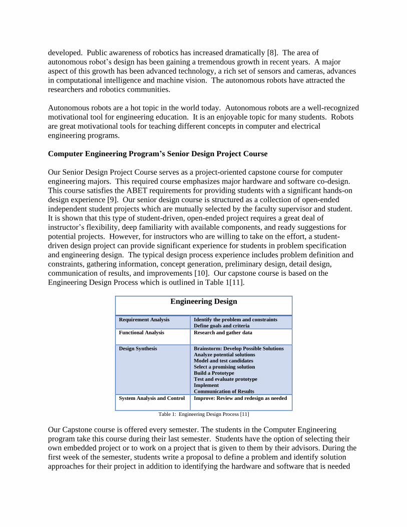
communication of results, and improvements [10]. Our capstone course is based on the
Engineering Design Process which is outlined in Table 1[11].
Engineering Design
Requirement Analysis Identify the problem and constraints
Define goals and criteria Functional Analysis
Research and gather data
Design Synthesis Brainstorm: Develop Possible Solutions
Analyze potential solutions
Model and test candidates
Select a promising solution
Build a Prototype
Test and evaluate prototype
Implement
Communication of Results System Analysis and Control
Improve: Review and redesign as needed
Table 1: Engineering Design Process [11]
Our Capstone course is offered every semester. The students in the Computer Engineering
program take this course during their last semester. Students have the option of selecting their
own embedded project or to work on a project that is given to them by their advisors. During the
first week of the semester, students write a proposal to define a problem and identify solution
approaches for their project in addition to identifying the hardware and software that is needed
for their project. After several iterations, the advisor approves their proposal. The faculty adviser
will meet with each student individually on a weekly basis at a regularly scheduled, mutually
agreeable time. These meetings are considered mandatory for the students. Occasional conflicts
are inevitable, but the students need to understand that a portion of their grade for participation is
based on attendance at the weekly meetings. At each meeting, issues associated with the project
will be discussed and a status report will be provided by the student to the advisor. Students will
keep a daily journal/work log detailing the work that was done, how much time was spent that
day, and any technical details that might be needed for later reference. The faculty advisor keeps
notes of each meeting as well as action items to be accomplished for the next meeting.
Reviewing the log sheet from the previous meeting is a great way for the faculty to prepare for
the upcoming one and provides further evidence to the student of the meeting’s importance. At
the end of the semester, students turn in a final written report and a final presentation which is
evaluated by several faculty members from the department.
Robotics in Computer Engineering Program at Utah Valley University (UVU)
In order to prepare our computer engineering students for the embedded systems design
experience, which serves a critical element of their education; we offer two courses on embedded
system design. Embedded Systems I is a junior level course and Embedded Systems II is a
senior level course. However, these two courses on embedded systems design are not enough to
teach the students the skills that they need. The focus of our computer engineering capstone
design class has been the design of embedded systems. By requiring an embedded design project
in our capstone course, our students receive hands-on training in embedded systems that will
enable them after graduation. Robot design is a complex embedded systems design. This paper
presents the details of a project that our computer engineering student has done in the area of
robotics in their capstone course.
Project: Autonomous Robotic Hexapod
The objective of this project was to create a mechatronics system that incorporates embedded
programming, applied electrical theory, and dynamic mechanical design. The same design
principles applied to complex robots used in industry have been implemented in this simplistic
robot with the use of feedback control to sense its surroundings, process data, and make
decisions for determining its output. The legs of this hexapod include three rotating joints that
have been sourced with sensors embedded in the feet to detect contact with the ground. In
addition, this hexapod is equipped with a moving tail, 3-axis moving head, functioning
mandibles with pressure and range sensors, eyes with PIR sensors to detect motion of threats,
and a color sensor to allow its external shell to camouflage with its environment via RGB LED’s.
Internally, there are sensors to monitor servo thermal overload, battery voltage and amperage
draw. The hexapod functions by one of two modes: manual-mode by means of a Bluetooth
transmitter with navigating buttons, and auto-mode with the aid of sensors to navigate its
surroundings and defend itself from potential threats.
A system-level view of this project is shown in Figure 1. It outlines the raw components of the
overall project and how they interconnect. The system is comprised of two devices: transmitter
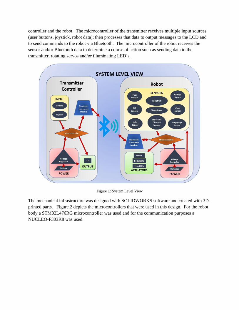
controller and the robot. The microcontroller of the transmitter receives multiple input sources
(user buttons, joystick, robot data); then processes that data to output messages to the LCD and
to send commands to the robot via Bluetooth. The microcontroller of the robot receives the
sensor and/or Bluetooth data to determine a course of action such as sending data to the
transmitter, rotating servos and/or illuminating LED’s.
Figure 1: System Level View
The mechanical infrastructure was designed with SOLIDWORKS software and created with 3D-
printed parts. Figure 2 depicts the microcontrollers that were used in this design. For the robot
body a STM32L476RG microcontroller was used and for the communication purposes a
NUCLEO-F303K8 was used.

Figure 2: Microcontrollers Used
Two PIR sensors were used for the eye shape for the robot and to detect movement. Color
sensors were used to detect ground color to camouflage body. Thermistors were used to monitor
servos temperatures. Ultrasonic sensors were used to detect distance of objects. Hall effect
sensors were used to detect grip on objects. An RGB LCD screen was used to display feedback
from robot on the transmitter. RGB LED were used to change body and eye colors. HC-05
Bluetooth module is used to send data between controller and robot wirelessly. Figure 3 shows
the robot base PCB (front view) and Figure 4 shows transmitter’s PCB (front view).
Figure 3: Robot Base PCB – Front View
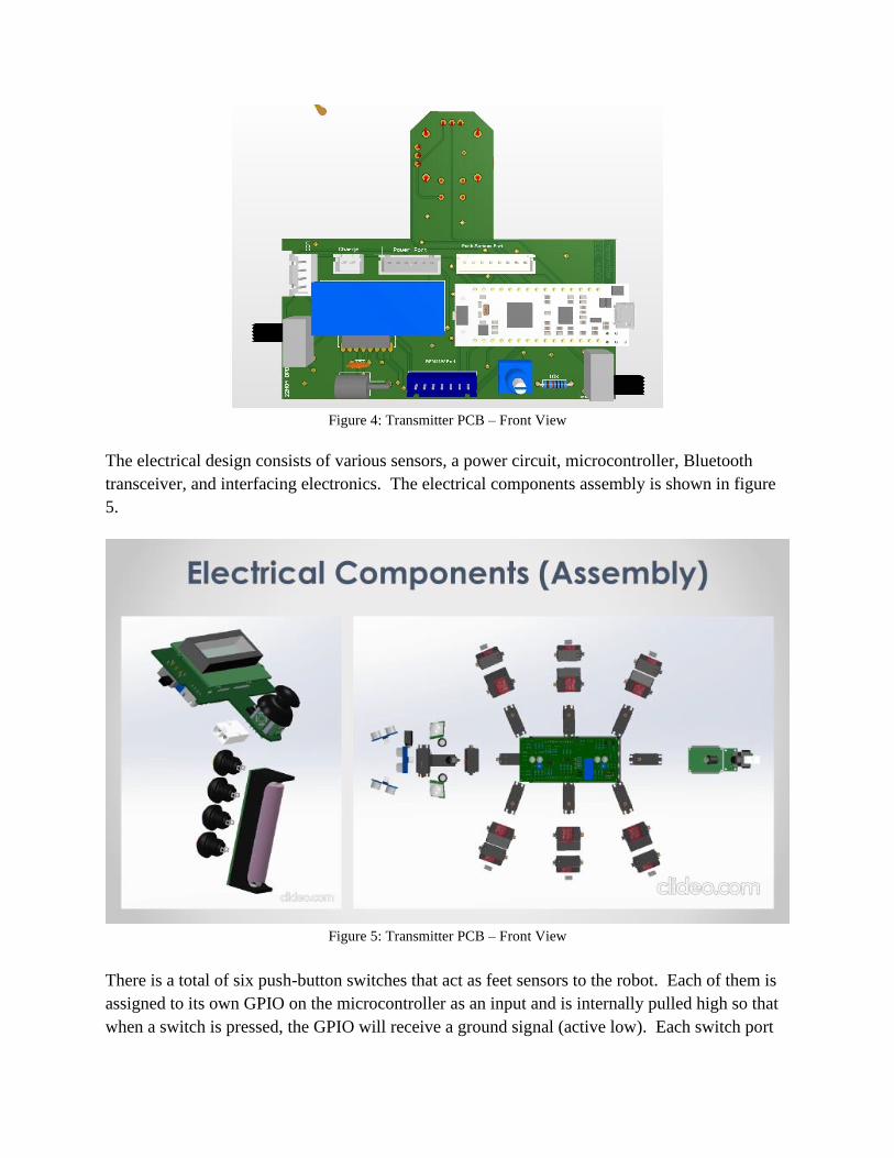
Figure 4: Transmitter PCB – Front View
The electrical design consists of various sensors, a power circuit, microcontroller, Bluetooth
transceiver, and interfacing electronics. The electrical components assembly is shown in figure
5.
Figure 5: Transmitter PCB – Front View
There is a total of six push-button switches that act as feet sensors to the robot. Each of them is
assigned to its own GPIO on the microcontroller as an input and is internally pulled high so that
when a switch is pressed, the GPIO will receive a ground signal (active low). Each switch port

also contains a thermistor to be connected to each main leg servo in order to monitor its
temperature due to the extensive force that it exerts supporting the robot weight. The CPU polls
those ADC thermistor readings every so often to readily shut down the servos in the event they
are overheating. There is a total of eight thermistors that monitor six legs, the mandibles, and the
neck. A thermistor was inserted on the mandibles servo since it is subject to overheating when
the servo doesn’t reach its rotational destination due to an obstacle being placed within the
mandibles that obstruct its full closure. The neck contains three servos, but only one of them
continuously supports the head upright so it is vulnerable to overheating within a matter of time.
The leg thermistors are hard-wired in parallel for each side of the body (total of two ports with 3
thermistors in parallel per port), and the neck and mandibles are wired in parallel for their own
port (total of 3 ADC ports for all 8 thermistors). If one or more thermistors increase in
temperature, the overall output voltage will change due to its voltage divider resistance changing.
The MCU will not know exactly which one is heating up since they are wired in parallel, but this
doesn’t matter since it would need to shut down if only one of them were to heat up. Wiring the
thermistors in parallel has liberated limited ADC GPIO’s to be used for other peripherals. Figure
6 depicts the base sensors schematic and figure 7 shows the complete base schematic.
Figure 6: Base Sensors Schematic
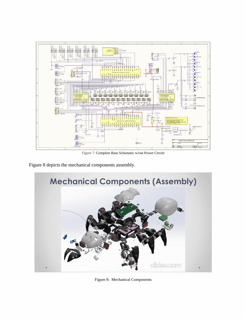
Figure 7: Complete Base Schematic w/out Power Circuit
Figure 8 depicts the mechanical components assembly.
Figure 8: Mechanical Components
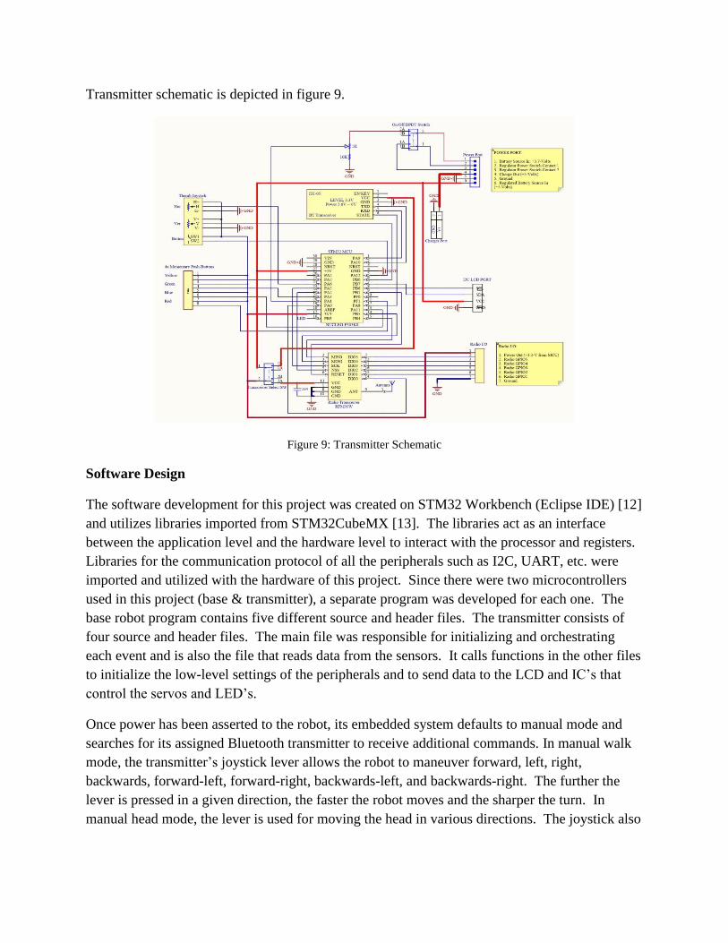
Transmitter schematic is depicted in figure 9.
Figure 9: Transmitter Schematic
Software Design
The software development for this project was created on STM32 Workbench (Eclipse IDE) [12]
and utilizes libraries imported from STM32CubeMX [13]. The libraries act as an interface
between the application level and the hardware level to interact with the processor and registers.
Libraries for the communication protocol of all the peripherals such as I2C, UART, etc. were
imported and utilized with the hardware of this project. Since there were two microcontrollers
used in this project (base & transmitter), a separate program was developed for each one. The
base robot program contains five different source and header files. The transmitter consists of
four source and header files. The main file was responsible for initializing and orchestrating
each event and is also the file that reads data from the sensors. It calls functions in the other files
to initialize the low-level settings of the peripherals and to send data to the LCD and IC’s that
control the servos and LED’s.
Once power has been asserted to the robot, its embedded system defaults to manual mode and
searches for its assigned Bluetooth transmitter to receive additional commands. In manual walk
mode, the transmitter’s joystick lever allows the robot to maneuver forward, left, right,
backwards, forward-left, forward-right, backwards-left, and backwards-right. The further the
lever is pressed in a given direction, the faster the robot moves and the sharper the turn. In
manual head mode, the lever is used for moving the head in various directions. The joystick also
includes a push-button to manually open and close the mandibles. The transmitter includes four
other momentary push-button switches that are used for various functions:
• Yellow - alternating among operational modes (auto, manual walk, and manual
head), and acknowledging messages the robot sends to the LCD
• Green – sends a command to the robot to perform a dance
• Blue – sends a command to the robot to go into pre-attack mode by crouching
down and opening mandibles as a warning to the intruder of a potential attack
• Red – sends a command to the robot to go into full attack mode by leaping
forward towards the intruder to bite (body changes red to reflect anger mood)
In auto-mode, the robot relies on its sensors to gather information of its surroundings and then
base its actions on the sensor data. The range sensors located on the front and sides detect the
distance of nearby objects to determine its course. The front range sensor oscillates up and down
with a small motor to allow it to vary its angle for reading data at different points. The side
range distance sensors affixed to the mandibles are solely used for detecting objects on its left
and right sides used to assist in its navigational course. As the robot approaches an oncoming
object, a programmed algorithm will have it back-up or turn around based on the amount of
space given. As the robot moves away and the object continues to be within 30-cm of the front
range sensor, then it’s assumed that the intruder is following it as a potential threat. In this case,
the robot will go into pre-attack mode by crouching down, changing its body and eye color to
reflect its state of defense mood, and then fully opening its mandibles as a warning sign of
potentially asserting a defense attack. If the intruder continues to be a threat, then the robot will
spring forward and attempt to grab it. Upon attack, if the intruder is within the proximity of the
mandibles detected by the front range sensor, the robot will clench its mandibles to gain a firm
grip of it. Once closed, if the magnet inside is not within the proximity of the hall sensor due to
an obstruction of the mandibles completely closing, then it is assumed that a successful grip has
occurred. At this point, the robot will assert aggressive behavior by thrusting its head side to
side for a few seconds meanwhile clenching onto the intruder. If the threat is no longer detected
by both the hall sensor and front range sensor, then the robot assumes that the intruder has
vanished and proceeds with its journey.
During the robot’s course of walking, each foot contact with the ground sends a signal to the
microcontroller that there is indeed a path to continue walking on. If it were to approach a
falling edge, the foot sensor wouldn’t detect any pressure beneath and thus prevent itself from
falling. The foot sensor is also useful in ridged terrain environments where cavities in the
ground may need the leg to lower itself further for proper stability.
The eyes are made up of PIR sensors that detect motion. Any motion on the left side will trigger
the head to turn left and any motion on the right will trigger the head to turn right. Each time the
head is turned, the microcontroller generates a different random number (via RNG) that
determines its degree of movement. Although these sensors don’t serve much of a purpose in
making decisions, they are primarily used to reflect natural movements of an insect to depict
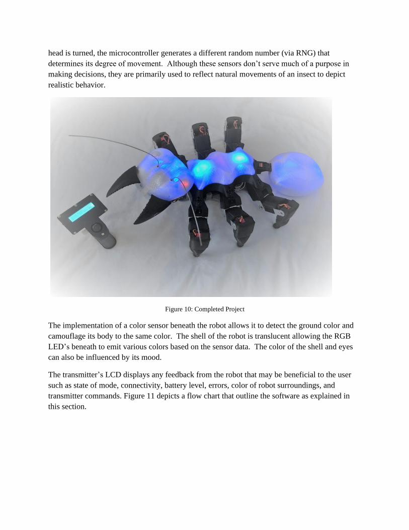
realistic behavior.
Figure 10: Completed Project
The implementation of a color sensor beneath the robot allows it to detect the ground color and
camouflage its body to the same color. The shell of the robot is translucent allowing the RGB
LED’s beneath to emit various colors based on the sensor data. The color of the shell and eyes
can also be influenced by its mood.
The transmitter’s LCD displays any feedback from the robot that may be beneficial to the user
such as state of mode, connectivity, battery level, errors, color of robot surroundings, and
transmitter commands. Figure 11 depicts a flow chart that outline the software as explained in
this section.
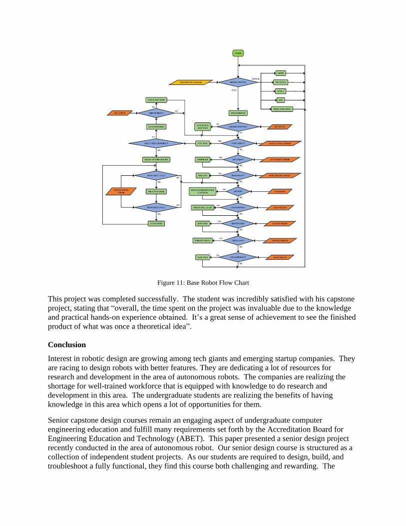
Figure 11: Base Robot Flow Chart
This project was completed successfully. The student was incredibly satisfied with his capstone
project, stating that “overall, the time spent on the project was invaluable due to the knowledge
and practical hands-on experience obtained. It’s a great sense of achievement to see the finished
product of what was once a theoretical idea”.
Conclusion
Interest in robotic design are growing among tech giants and emerging startup companies. They
are racing to design robots with better features. They are dedicating a lot of resources for
research and development in the area of autonomous robots. The companies are realizing the
shortage for well-trained workforce that is equipped with knowledge to do research and
development in this area. The undergraduate students are realizing the benefits of having
knowledge in this area which opens a lot of opportunities for them.
Senior capstone design courses remain an engaging aspect of undergraduate computer
engineering education and fulfill many requirements set forth by the Accreditation Board for
Engineering Education and Technology (ABET). This paper presented a senior design project
recently conducted in the area of autonomous robot. Our senior design course is structured as a
collection of independent student projects. As our students are required to design, build, and
troubleshoot a fully functional, they find this course both challenging and rewarding. The
students’ feedback and their final project presentation indicate that they have pride in their
project accomplishments and have gained confidence in their engineering abilities.
References
1. Wikipedia, https://en.wikipedia.org/wiki/Robot , accessed on 4/11/2021.
2. Definition of “robot”. Oxford English Dictionary, Retrieved November 27, 2016.
3. Wikipedia, https://en.wikipedia.org/wiki/Autonomous_robot#History_and_development , accessed on
4/13/2021.
4. Lassa, Todd "The Beginning of the End of Driving". Motor Trend, January 2013.
5. "European Roadmap Smart Systems for Automated Driving", EPoSS, 2015.
6. Lim, Hazel Si Min; Taeihagh, Araz, "Algorithmic Decision-Making in AVs: Understanding Ethical and
Technical Concerns for Smart Cities". Sustainability, 11 (20): 5791, 2019.
7. Robotics: A Brief History, https://cs.stanford.edu/people/eroberts/courses/soco/projects/1998-
99/robotics/history.html , accessed on 4-17-2021.
8. Gennert, Michael, “Robotics as an Undergraduate Major: 10 Years’ Experience”, Proceedings of American
Society for Engineering Education, 2018.
9. ABET, Inc. Criteria for Accrediting Engineering Programs, http://abet.org, 2013.
10. Dieter, George and Linda Schmidt, “Engineering Design”, 4th edition, McGraw-Hill, 2009.
11. Prairie, Michael, et al., “Introducing Systems Engineering Concepts in a Senior Capstone Design Course”,
Proceedings of American Society for Engineering Education, 2012.
12. STMicroelectronics, "Download STM32 Workbench IDE," OpenSTM32 Community, 2020. [Online].
Available: www.openstm32.org. [Accessed February 2019].
13. STMicroelectronics, "STM32CubeMX Software Download," 2020. [Online]. Available:
https://www.st.com/en/development-tools/stm32cubemx.html. [Accessed February 2019].