design and development of an optically accessible high
TRANSCRIPT
University of Texas at El PasoDigitalCommons@UTEP
Open Access Theses & Dissertations
2012-01-01
Design and Development of an OpticallyAccessible High Pressure CombustorJesus NunezUniversity of Texas at El Paso, [email protected]
Follow this and additional works at: https://digitalcommons.utep.edu/open_etdPart of the Art and Design Commons
This is brought to you for free and open access by DigitalCommons@UTEP. It has been accepted for inclusion in Open Access Theses & Dissertationsby an authorized administrator of DigitalCommons@UTEP. For more information, please contact [email protected].
Recommended CitationNunez, Jesus, "Design and Development of an Optically Accessible High Pressure Combustor" (2012). Open Access Theses &Dissertations. 2155.https://digitalcommons.utep.edu/open_etd/2155
DESIGN AND DEVELOPMENT OF AN OPTICALLY ACCESSIBLE HIGH
PRESSURE COMBUSTOR
JESUS NUNEZ MICHEL
Mechanical Engineering Department
APPROVED:
Norman Love, Ph. D., Chair
Ahsan Choudhuri, Ph.D.
Jose F. Espiritu, Ph.D.
Benjamin C. Flores, Ph.D.
Interim Dean of the Graduate School

Copyright ©
by
Jesus Nunez Michel
2012

DESIGN AND DEVELOPMENT OF AN OPTICALLY ACCESSIBLE HIGH
PRESSURE COMBUSTOR
by
JESUS NUNEZ MICHEL
THESIS
Presented to the Faculty of the Graduate School of
The University of Texas at El Paso
in Partial Fulfillment
of the Requirements
for the Degree of
MASTER OF SCIENCE
Department of Mechanical Engineering
THE UNIVERSITY OF TEXAS AT EL PASO
May 2012

iv
Acknowledgments
I would like to acknowledge my advisor and mentor Dr. Norma Love for providing me with the
opportunity and encouragement to follow my academic pursuits. Dr. Ahsan Choudhuri, CSERT
Lab, and Loya Innovation Fund for providing the funding and opportunity to conduct this
research. Also would like to acknowledge my lab coworkers Sudipa Sarker and Carlos Valdez.
v
Abstract
Currently in the US there is a push to reduce the nation’s energy dependence from foreign fuel
sources. One of the most abundant fuels in the US is coal with the nation’s coal reserve
accounting for 25% of the coal in the world. Due to coal being an abundant resource in the US
and the need to reduce the dependency on foreign fuel sources coal derived synthetic fuels have
been studied for use in gas turbines. Modern gas turbine combustors must operate over a range of
different fuel compositions which includes fuels with high hydrogen fuel content (HHC). To
ensure the implementation of HHC in power generation without negotiating operational or
emission advantages, a study of the flame stability regime and behavior of HHC under realistic
gas turbine condition is needed. Thus this thesis presents the development of an optically
accessible high-pressure turbine combustor. The design parameters of the combustor developed
are based on a 500 kW power and 1.5 MPa pressure which is representative of an actual gas
turbine. Furthermore, the combustor has the flexibility of operating with variable syngas
compositions along with a variety of fuel to analyze the flame structure, flow field
characterization using high speed particle image velocimetry (PIV), and flashback propensity in
high hydrogen content fuel under realistic gas turbine condition. The combustor has been built
and tested and is available for use for testing of a variety of fuels.
vi
Table of Content
Acknowledgments………………………………………………………………………………..iv
Abstract .......................................................................................................................................... v
Table of Contents ...........................................................................................................................vi
List of Tables .............................................................................................................................. viii
List of Figures ............................................................................................................................... ix
List of Nomenclature/Symbols…………………………………………………….…………….xi
1. Introduction ................................................................................................................................. 1
1.1 INTRODUCTION ................................................................................................................. 1
1.2 OBJECTIVE.......................................................................................................................... 2
1.3 DESIGN PARAMETERS AND CONFIGURATION ......................................................... 3
1.4 THESIS ORGANIZATION .................................................................................................. 4
2. Background and Literature Review ............................................................................................ 5
2.1 UTEP AMBIENT COMBUSTOR ........................................................................................ 5
2.2 HIGH PRESSURE COMBUSTORS .................................................................................... 6
3. Design Methodology ................................................................................................................... 9
3.1 ADIABATIC FLAME TEMPERATURE ............................................................................ 9
3.2 WALL TEMPERATURE ..................................................................................................... 9
3.3 FINITE ELEMENT ANALYSIS ........................................................................................ 11
3.3.1 Quartz Tube .................................................................................................................. 11
3.3.2 Combustion Chamber ................................................................................................... 14
3.3.3 Window Covers ............................................................................................................ 17
3.3.4 FEA of Stand Mounting Connection ............................................................................ 18
3.4 HEAT TRANSFER ANALYSIS ........................................................................................ 21
3.4.1 Quartz Tube Main Combustion Configuration ............................................................. 21
3.4.2 Stainless Steel Main Combustion Chamber Configuration .......................................... 23
3.5 PUMP SIZING AND MASS FLOW ANALYSIS ............................................................. 23
4. Experimental Results ............................................................................................................... 26

vii
4.1 INLET MANIFOLD ........................................................................................................... 29
4.1.1 Design Description and Dimensions ............................................................................ 29
4.1.2 Combustor Operation ................................................................................................... 30
4.2 FRONT CAP ....................................................................................................................... 31
4.2.1Design Description and Dimensions ............................................................................. 31
4.2.2 Ignition System ............................................................................................................. 33
4.3 AIR DISTRIBUTOR........................................................................................................... 33
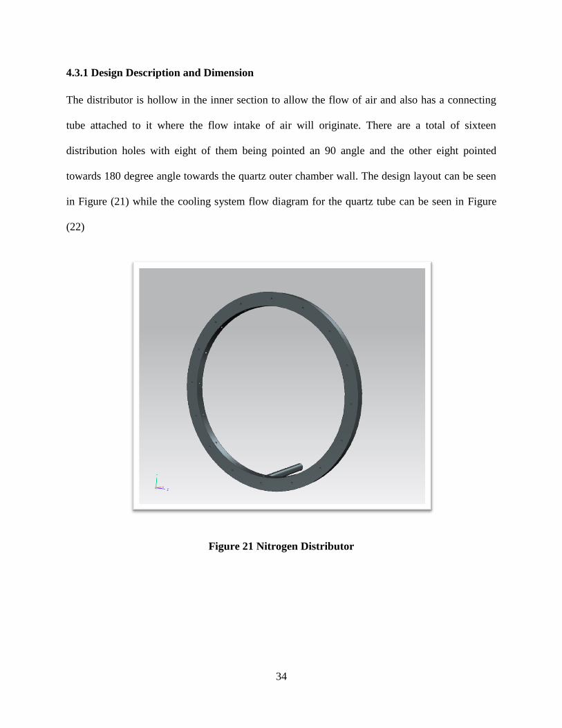
4.3.1 Design Description and Dimension .............................................................................. 34
4.4 STAINLESS STEEL COMBUSTION CHAMBER........................................................... 35
4.4.1 Design Description and Dimension .............................................................................. 35
4.5 WINDOW COVERS/ INTERCHANGEABLE INSTRUMENTATION PORTS ............. 38
4.5. 1Purpose and Design Dimensions .................................................................................. 38
4.6 CYLINDRICAL QUARTZ TUBE AND RECTANGULAR WINDOWS ........................ 41
4.6.1 Purpose and Design Dimensions .................................................................................. 41
4.7 END CAP ............................................................................................................................ 43
4.7.1 Converging Nozzle ....................................................................................................... 44
4.7.2 Nitrogen Exhaust Disk.................................................................................................. 46
4.7.2 Main End Cap ............................................................................................................... 47
4.8 BOLT SPECIFICATION .................................................................................................... 48
4.9 TEST MOUNTING............................................................................................................. 52
4.10 GASKETS ......................................................................................................................... 54
4.11 MANUFACTURING ........................................................................................................ 54
5. Summary and Conclusions ....................................................................................................... 56
5.1 CONCLUSION ................................................................................................................... 56
5.2 FUTURE WORK ................................................................................................................ 56
5.3 FUTURE TESTING ............................................................................................................ 57
Reference ...................................................................................................................................... 58
Appendix ....................................................................................................................................... 61
Vita ................................................................................................................................................ 81

viii
List of Tables
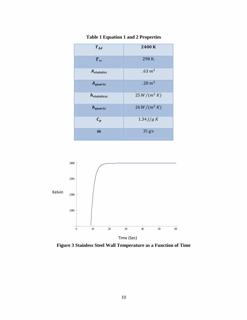
Table 1 Equation 1 and 2 Properties ............................................................................................. 10
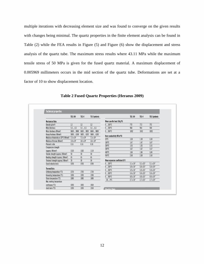
Table 2 Fused Quartz Properties (Heraeus 2009) ......................................................................... 12
Table 3 410 Stainless Steel Properties (Azom)............................................................................. 15
Table 4 Steel A36 Properties (Matweb) ........................................................................................ 19
Table 5 Equation 6 Properties ....................................................................................................... 22
Table 6 Equation 11 Properties ..................................................................................................... 51
Table 7 Equation 12 Properties ..................................................................................................... 51
Table 8 Bolt Stresses ..................................................................................................................... 52
Table 9 Heat of Formation at 298 K (kJ/kmol) ............................................................................. 61
Table 10 Specific Heat 2415 K (kJ/kmol-k) ................................................................................. 61

ix
List of Figures
Figure 1 CAD Model High Pressure Combustor ............................................................................ 4
Figure 2 UTEP Ambient Combustor .............................................................................................. 6
Figure 3 Stainless Steel Wall Temperature as a Function of Time............................................... 10
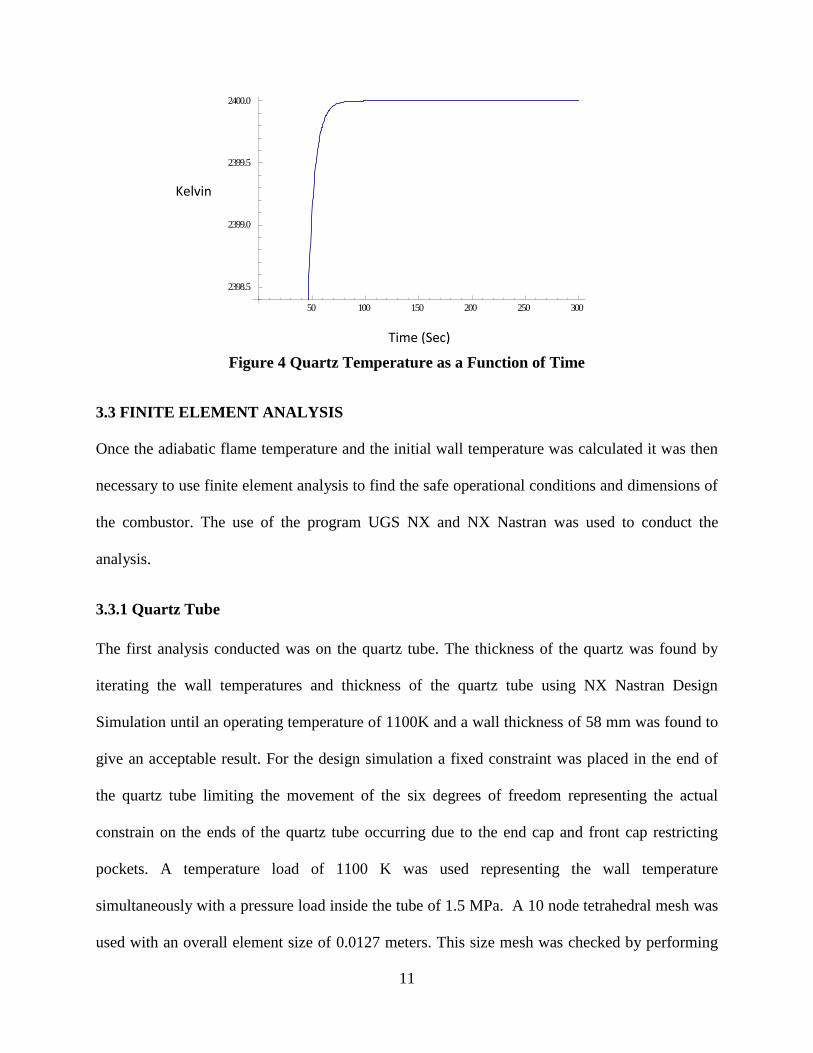
Figure 4 Quartz Temperature as a Function of Time .................................................................... 11
Figure 5 Quartz Tube Displacement ............................................................................................. 13
Figure 6 Quartz Tube Stress Analysis ......................................................................................... 13
Figure 7 FEA Combustion Chamber ............................................................................................ 16
Figure 8 FEA Displacement Combustion Chamber ..................................................................... 16
Figure 9 FEA Displacement Analysis Window Covers ............................................................... 17
Figure 10 FEA Stress Analysis ..................................................................................................... 18
Figure 11 Stress Analysis Curvature Mounting Connection ........................................................ 20
Figure 12 Displacement Analysis Curvature Mounting Connection ............................................ 20
Figure 13 Cooling Coil ................................................................................................................. 24
Figure 14 Design Process (Budynas 2008) ................................................................................... 27
Figure 15 Overall Design of Combustion Chamber ..................................................................... 28
Figure 16 Inside Schematic of Combustion Chamber .................................................................. 28
Figure 17 Inlet Manifold ............................................................................................................... 30
Figure 18 Front Cap With Quartz Configuration Slot .................................................................. 32
Figure 19 Front Cap Connecting Side to Inlet Manifold .............................................................. 32
Figure 20 Ignition System ............................................................................................................. 33
Figure 21 Nitrogen Distributor ..................................................................................................... 34
Figure 22 Nitrogen Fuel/Air Flow Schematic .............................................................................. 35
Figure 23 Combustor Stainless Steel Side View .......................................................................... 36
Figure 24 Stainless Steel Chamber ............................................................................................... 37
Figure 25 Stainless Steel Chamber Front View ............................................................................ 37
Figure 26 Stainless Steel Rectangular Window Cover ................................................................. 39
Figure 27 Stainless Steel Round Window Cover .......................................................................... 39
Figure 28 Stainless Steel Instrumentation Port ............................................................................. 40
Figure 29 Stainless Steel Instrumentation Port Inner View .......................................................... 40
Figure 30 Quartz Transmission Spectrum .................................................................................... 42
Figure 31 Square Quartz Windows ............................................................................................... 42
Figure 32 Inner Quartz Tube ......................................................................................................... 43
Figure 33 End Cap Assembly ....................................................................................................... 44
Figure 34 Exit Nozzel Bolt View.................................................................................................. 45
Figure 35 Exit Nozzle ................................................................................................................... 45
Figure 36 Nitrogen Exhaust Disk ................................................................................................. 46
Figure 37 Solid Disk When Operating Without Nitrogen Cooling Flow ..................................... 47
Figure 38 Main End Cap ............................................................................................................... 48
Figure 39 12.7 Millimeter Diameter Bolt (Window Cover) [McMasters] ................................... 49

x
Figure 40 6.35 Millimeter Diameter Bolts (End Cap/ Front Cap) [McMasters] .......................... 50
Figure 41 Test Stand and Combustor............................................................................................ 53
Figure 42 Attachment Curvature .................................................................................................. 54

xi
Nomenclature/List of Symbols
= Area
=Exhaust Area
Throat Area
Coefficient of Thermal Expansion of Joint Material
Coefficient of Thermal Expansion of Bolt
=Specific Heat at Constant Pressure per Unit Mass
d = Diameter of bolt
= Thermal load
Fp = Preload
=fuel-air ratio
g=gravity constant
h = Heat transfer coefficient
= Total Head Loss
=Minor Head Loss
= Coefficient Of Friction Bolt
= Stiffness of bolt
= Stiffness of joint
=Length of Bolt
=Mass flow rate
=airflow rate
Ma=Mach number
P=Pressure
=Ambient Pressure
PC=Chamber pressure
=Exhaust Pressure
R=Universal gas constant
= Total thermal resistance
=Production of heat
=Temperature
=Adiabatic Flame temperature
= Initial torque
TC=Chamber temperature
=Free Stream Temperature
=Velocity
=Exhaust Velocity
v=Velocity
=Specific heat constant
1
1. Introduction
1.1 INTRODUCTION
Currently in the US there is a push to reduce the nation’s energy dependence from foreign
countries. One of the most abundant fuels in the US is coal with the nation’s coal reserve
accounting for 25% of the coal in the world [US DOE 2011]. Coal is primarily used for electric
power production and currently produces more than half the electricity produced in the US [US
DOE 2011]. Due to coal being an abundant resource in the US and the need to reduce the
dependency on foreign fuel sources coal derived synthetic fuels have been studied for use in gas
turbines. Gas turbines have been used for power generation since 1939 and were first explored
by the Brown Bovery Company located in Neuchâtel, Switzerland [ASME 1988]. Current
application for gas turbines include the gas and oil industry, emergency power generation
facilities, independent power production, and a number of other industrial applications [EPA
2000].
A gas turbine is an internal combustion engine operating with rotary motion. The main
components of the engine are the compressor, the combustor, and the turbine. In the compressor
section air is drawn in and compressed where it is then directed to the combustion chamber
where fuel is added, ignited, and burned. The hot gases produced are then routed to the turbine
section where energy from the exhaust gas is recovered in the form of shaft power. More than 50
% of the power produced is then routed to supply the motion of the compressor, while the rest is
available to drive and external load [EPA 2000]. The exiting heat content from the exhaust gas is
then discarded with the following applications: without heat recovery in an open cycle, recovered
with heat exchangers, and can be used to preheat the air entering the compressor in a

2
regenerating cycle, or recovered to produce steam used in a steam turbine for power production
in a Rankine cycle [EPA 2000]. Typical Brayton Cycle thermal efficiencies range from 15-42
percent [EPA 2000].
Synthetic fuels have the capability to produce lower pollutant emission compared to traditional
coal derived power sources. Due to the use of alternative types of fuels such as synthetic gas,
modern turbine combustors will be required to operate over a range of different fuel
compositions which includes fuels with high hydrogen fuels content. Hydrogen a common
component of a syngas fuel mixture cause high laminar flame speed, changes the range of
flammability limits, and increases the propensity of a flame to flashback [Daniele et al. (2010)].
Flashback is defined as the point when the flame propagates upstream of the region where it is
intended to affix. Flashback may occur due to propagation in the core flow, propagation in the
boundary layer, propagation due to combustion induced vortex breakdown, and propagation due
to combustion instabilities [Tse and Zhu 2004]. Due to the use of these newly developed fuels
the need to study flame characteristics under particularly realistic turbine conditions is needed.
1.2 OBJECTIVE
The main objective of this thesis is to detail the design of an optically accessible high pressure
combustor which can operate with a variety of fuels. This thesis will cover many design aspects
of the high pressure combustor test section which will incorporate the use of a cooling system,
fittings, and test facilities. Also included is the heat transfer analysis: FEA, CAD modeling,
manufacturing, part assembly, current status of the testing facility, and future work needed.

3
1.3 DESIGN PARAMETERS AND CONFIGURATION
The combustor is designed to operate up to 1.5 MPa and temperatures reaching up to 2400K.
This temperature and pressure is selected due to the high hydrogen fuel composition that will be
used in testing as well as pressure representative of an actual gas turbine. The air mass flow rate
is designed to be a maximum of 81.93 g/s and will be provided by a continuous compressed air
supply. The fuel used will be (H2-CO) with a maximum flow rate of 35.77 g/s, with hydrogen
being varied up to 30 percent of the fuel composition.
The combustor is composed of four primary modular sections including an inlet static mixer, an
inlet cap, an optically accessible combustion chamber, and a variable exhaust throat area
restrictor composed of a converging nozzle and exhaust. The combustor will incorporate a
cooling system in the inner and outer section of the combustor. The combustion chamber will
also be operable while accommodating a configurable quartz burner to help show how the burner
geometry can affect flashback and the use of instrumentation ports to measure pollutant
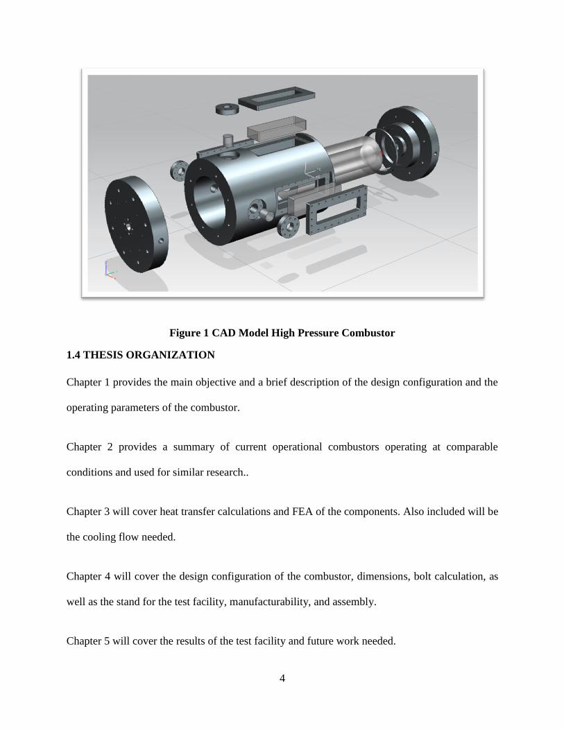
emissions. The CAD model of the combustor can be seen below in Figure (1)
4
Figure 1 CAD Model High Pressure Combustor
1.4 THESIS ORGANIZATION
Chapter 1 provides the main objective and a brief description of the design configuration and the
operating parameters of the combustor.
Chapter 2 provides a summary of current operational combustors operating at comparable
conditions and used for similar research..
Chapter 3 will cover heat transfer calculations and FEA of the components. Also included will be
the cooling flow needed.
Chapter 4 will cover the design configuration of the combustor, dimensions, bolt calculation, as
well as the stand for the test facility, manufacturability, and assembly.
Chapter 5 will cover the results of the test facility and future work needed.

5
2. Background and Literature Review
As a starting point in the design and development of the high pressure combustor presented in
this thesis it was necessary to investigate previous design and tested combustors operating under
similar conditions. This chapter will review some of these combustors in operation and discuss
the similarities and differences between this current design and those previously developed. Also
included will be the current operation ambient combustor being used at the University of Texas
at El Paso (UTEP) and the influence it had on the development of the current design.
2.1 UTEP AMBIENT COMBUSTOR
Currently at UTEP there is an operational optically accessible combustor operating under
ambient conditions. The design is of importance due to the correlation and design parameters
taken from the previous design and used in the current design. The main area of research the
ambient combustor has been used for pertains to flashback properties in syngas fuels. Various
test and journal publications have been published (Bidhan et. al 2011), using the ambient
combustor as a test facility, pertaining to that study.
Different fuel mixtures have been used in the combustor including and
mixtures. The combustor rig is shown in Figure (2) and is set up using four configurable models:
the inlet manifold, static mixer, swirler burner with quartz tube, and the combustion chamber.
The quartz windows located on the main combustion section allow for high speed imaging of
flashback characteristics. The inner dimensions for the combustor is 130 millimeters similar to
the high pressure combustor as well as the fuel and air inlet manifold design and static mixer.

6
Figure 2 UTEP Ambient Combustor
2.2 HIGH PRESSURE COMBUSTORS
There are currently a number of different combustors being used for related experiments and
using similar operating conditions. These combustor designs were reviewed and taken into
consideration with the current design. A brief description and operating conditions are listed
below.
In Cambridge University High Pressure Combustion Lab a combustor was design to operate up
to 600 °C and 1 MPa with an air mass flow rate of .9 kg/s. The use of an optical section with
120x130 mm^2 windows were used and combustion takes place in a 130 mm diameter quartz
tube, the same dimensions and materials as our current design. The Cambridge combustor also
7
implements a cooling system with air flowing between the inside quartz chamber and outer
chamber and was used as a starting reference point for the cooling system of the current
combustor developed. The pressure drop in the combustor is controlled using a variable area
flow restrictor in the exit nozzle similar to our current design (Cambridge 2009).
The University of California Irvine Combustion Laboratory (UCICL) has two operational testing
combustors. One used for high pressure combustion experiments with optical access, the second
used for long duration experiments. The flow rate reaching 1 kg/s and pressure up to 15 bar
(Irvin 2011).
The National Energy Technology Laboratory (NETL) has two operational high-pressure
combustor facilities. A dynamic gas turbine with optical access and operating pressures of up to
10 bar and air flow at .75 kg/s while using natural gas and liquid fuels. The second combustion
facility is used for computational fluid dynamic testing and modeling of combustion. The
combustor has optical access and can operate with variable fuel and pressures up to 22 bar
(National Energy Technology Laboratory)
Pennsylvania State University’s High Pressure Combustion Lab performs test in the area of
solid-fuel formulation, development, and propulsive performance. The use of a high Solid
Propellant Strand Burner (SPSB) with pressure in the chambers reaching up to 655 bar with
optical access used to investigate the flame spreading process. Also in use is an “Ultra High
Pressure Strand Burner” with pressures up to 2068 bar (PSU 2011).
Physical Science Inc. has developed an optically accessible combustor for planar laser induced
fluorescence measurements. The combustor utilizes commercial styled gas-turbine fuel injectors
and has the capability of operating at pressures up to 50 bars. Current work has been limited to

8
operating at 20 bars with a maximum flow rate of 0.4 kg/s. The inlet air is preheated to a
temperature ranging from 400 K to 550 K before combustion. The combustor design consists of
four main components: a pressure vessel with inlet and exhaust flanges, fuel injection support
and linear system, water cooled exhaust orifice, and a water cooled exhaust test section. The
combustion gases are contained using a ceramic liner that protects the chamber from the heat
load of the flame. The region between the liner and outer pressure vessel is purged with nitrogen
flow. As the exhaust gas exists the chamber, it is water cooled in the exhaust section (J.H.
Frank, M. F. Miller, M G. Allen)
A high-pressure design was also designed in Italy using natural gas and hydrogen as the fuel
source. The combustor is rated at 10 bars and can operate under duel fuel operation (liquid and
gaseous). An axial swirler device is used operating with 8 holes for fuel injection. The
combustor is air-cooled and utilizes 800 louvers to cool down the chamber wall. The flame is
stabilized using a combination of a swirler as well as recirculation of air. The test rig consists of
an alloy steel pressure vessel, designed in modular form, utilizing a lamination valve at the exit
to control the pressure in the combustor. The combustor metal temperature, air flow, and burner
exit temperatures are recorded using thermocouples with an operating range of 400 to 1200 °C.
The use of pressure taps is also implemented to monitor pressure drops and high frequency
response pressure transducers to measure pressure fluctuation (Tomezak, et al)
Sato study involved a high pressure combustor with a cylindrical section of 500mm and a length
up to 600 mm for combustion. The use a removable electric heater is used for ignition. The
combustor has optical access with nine windows on the chamber walls. The pressure rating of the
chamber reaching up to 200 bar and temperatures reaching up to 900 K. Fuel is sprayed with the
use of a high pressure pump and injected into the accumulator (Konishi et al., 1988).
9
3. Design Methodology
3.1 ADIABATIC FLAME TEMPERATURE
The first step in the design of the combustor was to calculate the adiabatic flame temperature of
combustion. The use of the software STANJAN was used to calculate the adiabatic temperature.
The values used for calculation can be found in Appendix A. The fuels used were a mixture of
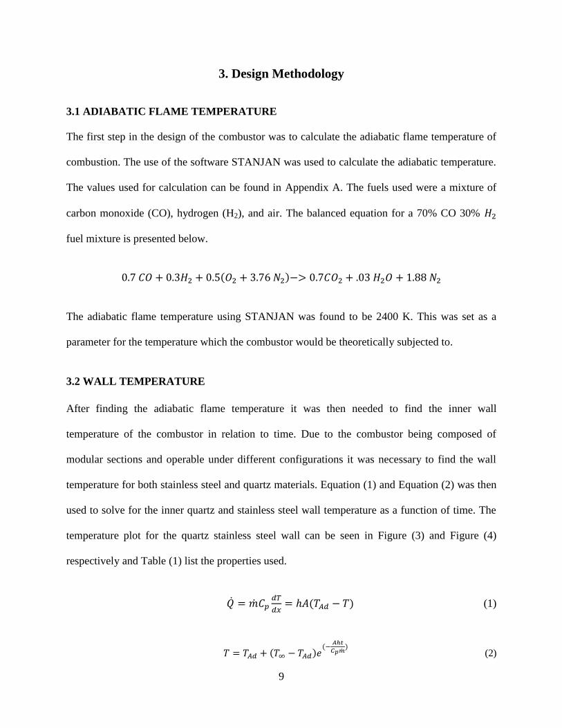
carbon monoxide (CO), hydrogen (H2), and air. The balanced equation for a 70% CO 30%
fuel mixture is presented below.
( )
The adiabatic flame temperature using STANJAN was found to be 2400 K. This was set as a
parameter for the temperature which the combustor would be theoretically subjected to.
3.2 WALL TEMPERATURE
After finding the adiabatic flame temperature it was then needed to find the inner wall
temperature of the combustor in relation to time. Due to the combustor being composed of
modular sections and operable under different configurations it was necessary to find the wall
temperature for both stainless steel and quartz materials. Equation (1) and Equation (2) was then
used to solve for the inner quartz and stainless steel wall temperature as a function of time. The
temperature plot for the quartz stainless steel wall can be seen in Figure (3) and Figure (4)
respectively and Table (1) list the properties used.
( ) (1)
( ) (
) (2)
10
Table 1 Equation 1 and 2 Properties
K
( )⁄
( )⁄
35 g/s
Figure 3 Stainless Steel Wall Temperature as a Function of Time
0 10 20 30 40 50 60
2385
2390
2395
2400
Time (Sec)
Kelvin
11
Figure 4 Quartz Temperature as a Function of Time
3.3 FINITE ELEMENT ANALYSIS
Once the adiabatic flame temperature and the initial wall temperature was calculated it was then
necessary to use finite element analysis to find the safe operational conditions and dimensions of
the combustor. The use of the program UGS NX and NX Nastran was used to conduct the
analysis.
3.3.1 Quartz Tube
The first analysis conducted was on the quartz tube. The thickness of the quartz was found by
iterating the wall temperatures and thickness of the quartz tube using NX Nastran Design
Simulation until an operating temperature of 1100K and a wall thickness of 58 mm was found to
give an acceptable result. For the design simulation a fixed constraint was placed in the end of
the quartz tube limiting the movement of the six degrees of freedom representing the actual
constrain on the ends of the quartz tube occurring due to the end cap and front cap restricting
pockets. A temperature load of 1100 K was used representing the wall temperature
simultaneously with a pressure load inside the tube of 1.5 MPa. A 10 node tetrahedral mesh was
used with an overall element size of 0.0127 meters. This size mesh was checked by performing
50 100 150 200 250 300
2398.5
2399.0
2399.5
2400.0
Kelvin
Time (Sec)
12
multiple iterations with decreasing element size and was found to converge on the given results
with changes being minimal. The quartz properties in the finite element analysis can be found in
Table (2) while the FEA results in Figure (5) and Figure (6) show the displacement and stress
analysis of the quartz tube. The maximum stress results where 43.11 MPa while the maximum
tensile stress of 50 MPa is given for the fused quartz material. A maximum displacement of
0.005969 millimeters occurs in the mid section of the quartz tube. Deformations are set at a
factor of 10 to show displacement location.
Table 2 Fused Quartz Properties (Heraeus 2009)

13
Figure 5 Quartz Tube Displacement
Figure 6 Quartz Tube Stress Analysis

14
3.3.2 Combustion Chamber
The finite element analysis was then needed to determine the wall thicknesses of the combustor
as well as the operational temperature of the combustor walls. The thickness of the combustion
wall was found by iterating the wall temperatures and thickness of the stainless steel chamber
using NX Nastran Design Simulation until an operating temperature of 350K and a wall
thickness of 88.9 millimeters was found to give an acceptable result. A 10 node tetrahedral mesh
was used with an overall element size of 12.7 millimeters. This size mesh was checked by
performing multiple iterations with decreasing element size and was found to converge on the
given results with changes being minimal. The stainless steel properties in the finite element
analysis can be found in Table (3) while the FEA results in Fig (7) and Fig (8) show the
displacement and stress analysis of the combustion chamber. The fixed constraints placed in the
FEA analysis model where located on the outer radial region of the end cap and front cap
representative of the constraints placed by the connection to the mounting of the frame limiting
the six degrees of freedom. The maximum stress results were 355.08 MPa while the minimum
yield strength is 575MPa given for the stainless steel 410. A maximum displacement of 0.13462
millimeters occurs in the mid-section of the stainless steel chamber. Maximum stresses were
found inside the window covers corners and edge of the instrumentation ports due to the change
of geometry inside the chamber causing stress raisers and creating a region where stress
concentration occurs (Budynas et al. 2008)

15
Table 3 410 Stainless Steel Properties (Azom)

16
Figure 7 FEA Combustion Chamber
Figure 8 FEA Displacement Combustion Chamber

17
3.3.3 Window Covers
The finite element analysis of the window covers was conducted. A 10 node tetrahedral mesh
was used with an overall element size of 5.08 millimeters. Stainless steel 410 was used and the
properties used in the finite element analysis can be found in Table (3) while the FEA results in
Figure (8) and Figure (9) show the displacement and stress analysis of the curvature connection.
The fixed constraints placed in the FEA analysis model where located on the bolt slots in the
window covers representative of the constraints placed by the steel bolts. A temperature load of
350 K and 1.5 MPa pressure was used in the analysis both loads placed on the inner quartz
window. The maximum yield strength results where 290.95 MPa while the minimum yield
strength of 575 MPa is given for the stainless steel material
Figure 9 FEA Displacement Analysis Window Covers

18
Figure 10 FEA Stress Analysis
3.3.4 FEA of Stand Mounting Connection
The finite element analysis of the design curvature connection between the mounting table and
combustor was also needed. A 10 node tetrahedral mesh was used with an overall element size of
5.08 millimeters. The A36 properties in the finite element analysis can be found in Table (4)
while the FEA results in Figure (11) and Figure (12) and show the displacement and stress
analysis of the curvature connection. The fixed constraints placed in the FEA analysis model
were located on the bottom ends of the model representing the constraints placed by the welding
of the curvature connection to the table used. A temperature load of 350 K was used and the
calculated weight of 76 kN was used to represent the actual weight of the combustor. Also a load
of 2.68 kN the maximum calculated force for the thrust created from the combustor, was placed
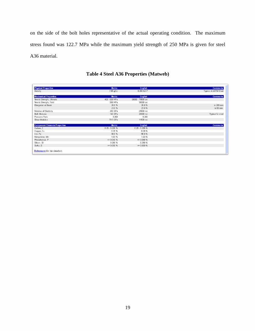
19
on the side of the bolt holes representative of the actual operating condition. The maximum
stress found was 122.7 MPa while the maximum yield strength of 250 MPa is given for steel
A36 material.
Table 4 Steel A36 Properties (Matweb)

20
Figure 11 Stress Analysis Curvature Mounting Connection
Figure 12 Displacement Analysis Curvature Mounting Connection

21
3.4 HEAT TRANSFER ANALYSIS
The calculations performed in the previous section show the need to lower the wall temperature
of both the combustor wall and the quartz tube. This is accomplished by two cooling methods.
One is the use of nitrogen inside the chamber between the outer stainless steel combustor and
quartz tube and the other is the use of copper cooling coils filled with running water wrapped
around the outside of the combustion chamber.
3.4.1 Quartz Tube Main Combustion Configuration
When operating with the quartz tube inside the stainless steel chamber FEA shows the need to
lower the temperature from 2400 Kelvin to 1100 Kelvin in order to avoid failure. This is
accomplished with the use of the nitrogen flow inside the combustion chamber. To calculate the
heat needed to be removed the use of Equation (3) was used with the specific heat based off of
the weight mass fraction sum.
∫ (
) (3)
A total of 162.57 kW was determined to be removed to maintain a safe wall temperature.
Equation (4) was then used to calculate the mass flow rate of nitrogen needed to remove 162.57
KW of heat giving us the mass flow rate of .19 kg/s nitrogen needed to bring the temperature of
the quartz tube down to 1100K.
∫
(4)

22
After obtaining the nitrogen flow needed to lower the wall temperature to 1100 Kelvin the next
step is to calculate the mass flow rate of water needed to cool down the outer stainless steel
chamber. Using Newton’s law of cooling seen in Equation (5)
( ) (5)
and rearranged to Equation (6)
( )
(6)
Table 5 Equation 6 Properties
K
Gives a total heat transfer of . Using Equation (7) to solve for the outer
surface temperature
( ) (7)
we obtain an outer surface temperature of 364 K. Using Equation (3) a total of 1.28 kW of
heat are needed to be removed. Then using Equation (8)

23
∫
(8)
We obtain a total mass flow rate of .008 kg/s of O needed to lower the outer stainless steel
wall temperature form 364K to 350 K. The low mass flow rate of water needed outside the
chamber is due to the inner cooling use of nitrogen inside the chamber.
3.4.2 Stainless Steel Main Combustion Chamber Configuration
When operating with the stainless steel chamber as the main combustion chamber the wall
temperatures can theoretically be 2400 K was determined. Due to these high temperatures the
need to cool the combustion walls to 350 K was determined finite element analysis. Using
Equation (3) the total amount of heat needed to be removed was found to be 393 KW. The mass
flow rate of needed to remove the heat is then calculated using Equation (9) this
corresponded to a water flow rate of 1.21 kg/s and the calculations can be seen in Appendix E.
Also included is the use CFD model using FLUENT simulating the use of a 2.54 cm thickness
cooling jacket showing the relationship of the mass flow rate and temperature under a constant
heat flux load and can be found in Appendix F.
∫
(9)
3.5 PUMP SIZING AND MASS FLOW ANALYSIS
Once the maximum mass flow rate was calculated the next step was to calculate the head losses
occurring in the piping system and the sizing of the pump was needed. The proposed cooling
system will incorporate the use of a 2,200 liter holding tank for the water, a 3.81 cm diameter
pipe acting as the connection from the tank to the pump and from the main combustion chamber

24
to the discharge line, as well as .635 cm diameter pipe that will wrap around the combustor as
shown in Figure (13). If operating for 30 minutes a total of 2,167 liters would be used.
Figure 13 Cooling Coil
Bernoulli's equation shown in Equation (10) was used to calculate the head losses.
(10)
Where includes the losses that occur due to entrance loss, friction loss in the 3.81 cm diameter
and .635 cm diameter line, valve fitting, 90 degree angle elbows, flow through branch losses, and
the exit loss occurring. An assumption of 10 meter of 3.81 cm steel pipe was assumed and 20
meters of .635 cm diameter pipe was assumed to be used in the cooling wrap of the combustor. A
total of four 90 degree angle elbows at 3.81 cm diameter where assumed, and 80 flow through
branches where assumed to be used in the wrap around the combustor. Also an elevation

25
difference of 1.2 meters where assumed to occur between the exit discharge line to the top of the
storage tank limit. A total of 9.37 meters of head loss was calculated to occur using the assumed
conditions. The pump sizing was calculated using Equation (11) and was found to be 145 W
pump needed assuming .76 pump efficiency. Complete calculations and values can be found in
Appendix E. When operating at 1.21 kg/s and under the assumption stated the use of a cast iron
centrifugal pump from Macmasters part number 99435k23 would be recommended with the
power output being 550 W and a mass flow of 132 Liters/minute while operating at 18.28 meters
of head.
(11)
26
4. Experimental Results
The results of the project will bring a unique testing facility that will allow future research in
flame characteristics of coal derived fuels of turbine combustors.
Some initial factors considered included cost analysis, operating temperatures, operating
pressure, dimensional restraints, weight restraints, safety assurance, and feasibility of
manufacturability of the final project. The main design parameters considered for this application
included a chamber operating pressure of 1.5 MPa and temperature of 2400 K. These must be
maintained while designing for safety assurance, dimensional restraint, weight, safety assurance,
and feasibility. This temperature and pressure were selected due to the high hydrogen fuel
composition that will be used in testing as well as the pressure representative of an actual gas
turbine.
The parameters define the synthesis stage of the design. Various preceding design concepts were
researched and investigated as well as independent proposals for the design was undertaken.
Each concept was analyzed, revised, improved, or discarded as the project progressed in an effort
to optimize the best design where all the set parameters are met.
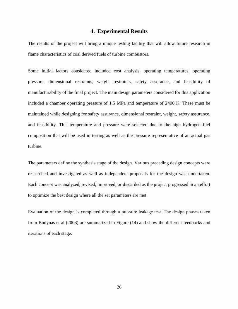
Evaluation of the design is completed through a pressure leakage test. The design phases taken
from Budynas et al (2008) are summarized in Figure (14) and show the different feedbacks and
iterations of each stage.
27
Figure 14 Design Process (Budynas 2008)
The description, dimensions, and purpose of each combustor part will be covered in the
upcoming sections. The overall design of the combustor can be seen in Figure (15) and Figure
(16) and include the three main sections of the combustion chamber. The end cap, main
combustion chamber, front cap, as well as various other components that were implemented in
the design.
Identification of Need
Definition of Problem
Synthesis
Analysis and Optimization
Evaluation

28
Figure 15 Overall Design of Combustion Chamber
Figure 16 Inside Schematic of Combustion Chamber

29
4.1 INLET MANIFOLD
The combustion process in some types of gas turbine can be classified into two types of
combustion. The first being a diffusion flame where the fuel air mixture occur in the combustion
chamber. The other is lean-premixed combustion where the fuel and air are previously mixed
away from the combustor section in an effort to obtain lean, uniform, unburned fuel/air mixture
[EPA 2000].
The combustor developed will be using a lean-premixed combustion process. The fuel and air is
mixed in the inlet manifold and then sent to the main combustion area. The inlet manifolds main
purpose is to act as a mixing area for the fuel and air mixture and to reduce injection induced
flow irregularities.
4.1.1 Design Description and Dimensions
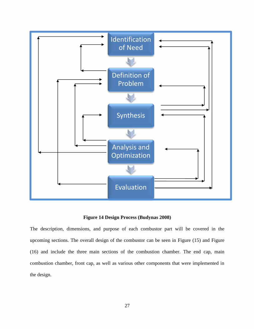
The inlet manifold in Figure (17) is compromised of three modular sections. The first acting as
the fuel/air inlet mixture section. The second is a removable static mixture section which is
composed of horizontal tubes located inside the chamber that remove irregularities and provide
an improvement towards laminar flow. This section is then attached to third section which
connects the inlet manifold to the main combustor section. The use of flanges are used as
connections between the inlet manifold, three modular sections, and the use of 6.35 millimeters
bolts connect the inlet manifold to the combustor connecting front cap. There is also a pressure
blow out valve located at the third modular section to provide a level of safety in case of
malfunction and an increase of pressure.
The given dimension of the inlet manifold is a 54.5 cm in total length with the three modular
section composed of 35 cm length for the inlet/initial mixture zone, 11.5 cm in length for the
30
static mixture section, and 7.6 cm length for the connecting section. The inner diameter of the
piping is 5.08 cm with a 6.35 mm thickness for all three sections. The material chosen was
stainless steel 316 due to availability and an FEA stress analysis resulting in adequate results.
Figure 17 Inlet Manifold
4.1.2 Combustor Operation
The fuel enters through four alternative injection holes located in the inlet section of the
manifold and is supplied by fuel and tanks. The compressed air enters trough one inlet located
next to the fuel injection ports supplied by a high pressure compressor. The fuel and air then
enter into the inlet manifold where initial mixing occurs then pass through a static mixture
section that assists in eliminating injection induce flow irregularities while insuring laminar flow.
From this section the flow is then directed to the main combustor.

31
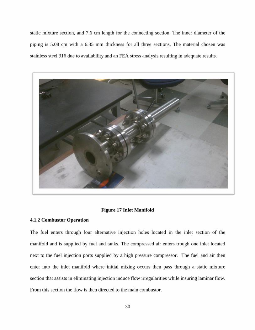
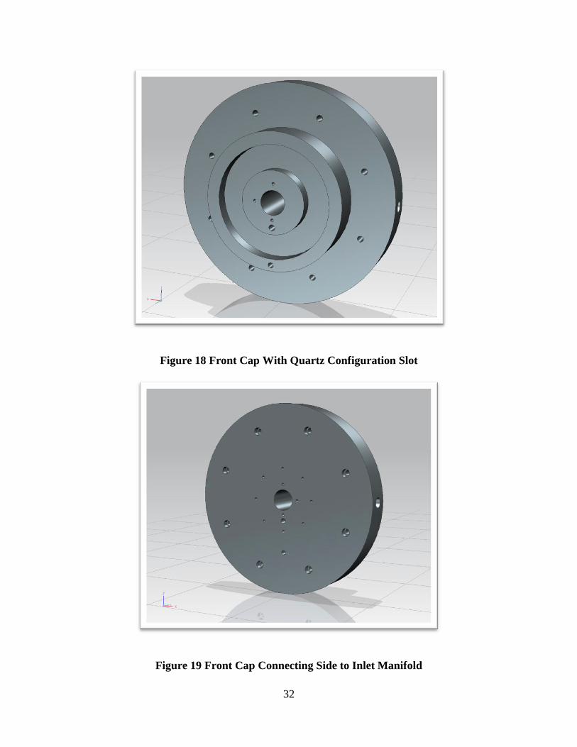
4.2 FRONT CAP
The front cap of the combustor can be seen in Figure (18) and Figure (19) and acts as an inlet to
the main combustor chamber. It houses the ignition system, the swirler, instrumentation holes,
and connects the inlet manifold to the main chamber.
4.2.1Design Description and Dimensions
The front cap is composed of one solid section and the draft with the exact dimensions can be
seen in Index C. The outer radius is 0.4572 meters with a 0.0508 m to 0.0381 m ratio converging
nozzle in the mid section of the model. The use of a converging nozzle is used to house the
swirler and allow the passage of fuel and air mixture into the main combustion chamber. The use
of eight 12.7 millimeters diameter bolts are used to connect the end cap to the main chamber
while the use of 6.35 millimeters diameter bolts are used to connect the inlet manifold to the
front cap. The combustor will operate under two different configurations. One includes the use of
a quartz tube and will be held in place in part by the front cap while the circular pocket seen in
Figure (17) is intended to hold the quartz tube in place.
32
Figure 18 Front Cap With Quartz Configuration Slot
Figure 19 Front Cap Connecting Side to Inlet Manifold

33
4.2.2 Ignition System
The ignition system is located in the main combustion chamber and the CAD model can be seen
in Figure (20). The use of a spark plug and methane will be used in the igniter and is currently
still being developed for the system. A 19.05 millimeters diameter hole that runs through the end
cap will hold the igniter in place and will provide the flame needed for ignition right below the
main fuel and air entry point.
Figure 20 Ignition System
4.3 AIR DISTRIBUTOR
One of the operational configurations of the combustor employs a quartz tube inside the stainless
chamber as the main combustion compartment. Due to high thermal stress, subjected to the
quartz chamber, it is then necessary to cool the outer quartz chamber with the use of nitrogen.
The need for a nitrogen distributor was then developed to provide even distribution of nitrogen
along the outer quartz chamber.
34
4.3.1 Design Description and Dimension
The distributor is hollow in the inner section to allow the flow of air and also has a connecting
tube attached to it where the flow intake of air will originate. There are a total of sixteen
distribution holes with eight of them being pointed an 90 angle and the other eight pointed
towards 180 degree angle towards the quartz outer chamber wall. The design layout can be seen
in Figure (21) while the cooling system flow diagram for the quartz tube can be seen in Figure
(22)
Figure 21 Nitrogen Distributor
35
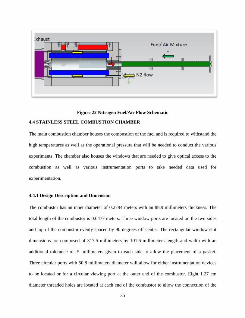
Figure 22 Nitrogen Fuel/Air Flow Schematic
4.4 STAINLESS STEEL COMBUSTION CHAMBER
The main combustion chamber houses the combustion of the fuel and is required to withstand the
high temperatures as well as the operational pressure that will be needed to conduct the various
experiments. The chamber also houses the windows that are needed to give optical access to the
combustion as well as various instrumentation ports to take needed data used for
experimentation.
4.4.1 Design Description and Dimension
The combustor has an inner diameter of 0.2794 meters with an 88.9 millimeters thickness. The
total length of the combustor is 0.6477 meters. Three window ports are located on the two sides
and top of the combustor evenly spaced by 90 degrees off center. The rectangular window slot
dimensions are composed of 317.5 millimeters by 101.6 millimeters length and width with an
additional tolerance of .5 millimeters given to each side to allow the placement of a gasket.
Three circular ports with 50.8 millimeters diameter will allow for either instrumentation devices
to be located or for a circular viewing port at the outer end of the combustor. Eight 1.27 cm
diameter threaded holes are located at each end of the combustor to allow the connection of the

36
front cap and end cap that will make up the combustor as a whole. The main material used is
stainless steel 410 due to the high yield stress and desired characteristics compared to other
stainless steel material. The side, angled, and front view of the combustor can be seen in Figure
(23), Figure (24), and Figure (25) respectively.
Figure 23 Combustor Stainless Steel Side View

37
Figure 24 Stainless Steel Chamber
Figure 25 Stainless Steel Chamber Front View

38
4.5 WINDOW COVERS/ INTERCHANGEABLE INSTRUMENTATION PORTS
4.5. 1Purpose and Design Dimensions
The window covers are needed to hold down the rectangular quartz windows. The outer
dimensions of the covers are made up of 16.51 cm by 38.1 cm length and width while the inner
dimensions are composed of 10.16 cm by 29.21 cm with an overall 2.54 cm thickness. The
windows covers will be attached to the combustor by the use of 24 6.35 millimeters diameter
bolts. The design configuration can be seen in Figure (26)
The instrumentation ports will be used for both optical accesses as well an interchangeable port
for the placement of thermocouple, burst disk, and or pressure transducer. It will also allow for
easy access to the inner combustion chamber and can be used as an entry point to do material
testing inside the combustor. The use of eight 12.7 millimeters diameter bolts are used to secure
ports in place. Figure (27) showing the circular port cover used when operating as a window, and
Figure (28) and Figure (29) showing the cover used when operating as an instrumentation port.
Both window cover and instrumentation ports are made of 410 stainless steel conforming to the
combustor and inlet and end cap material.

39
Figure 26 Stainless Steel Rectangular Window Cover
Figure 27 Stainless Steel Round Window Cover

40
Figure 28 Stainless Steel Instrumentation Port
Figure 29 Stainless Steel Instrumentation Port Inner View
41
4.6 CYLINDRICAL QUARTZ TUBE AND RECTANGULAR WINDOWS
4.6.1 Purpose and Design Dimensions
The combustor is designed to operate under two distinct conditions. One is with the use of a
quartz tube acting as the main combustion chamber. The other is with the tube removed allowing
the stainless steel chamber to act as the main chamber. This allows for different configurations
to show how the burner geometry can affect flashback as well as NOx emission due to being
dependent on burner design.
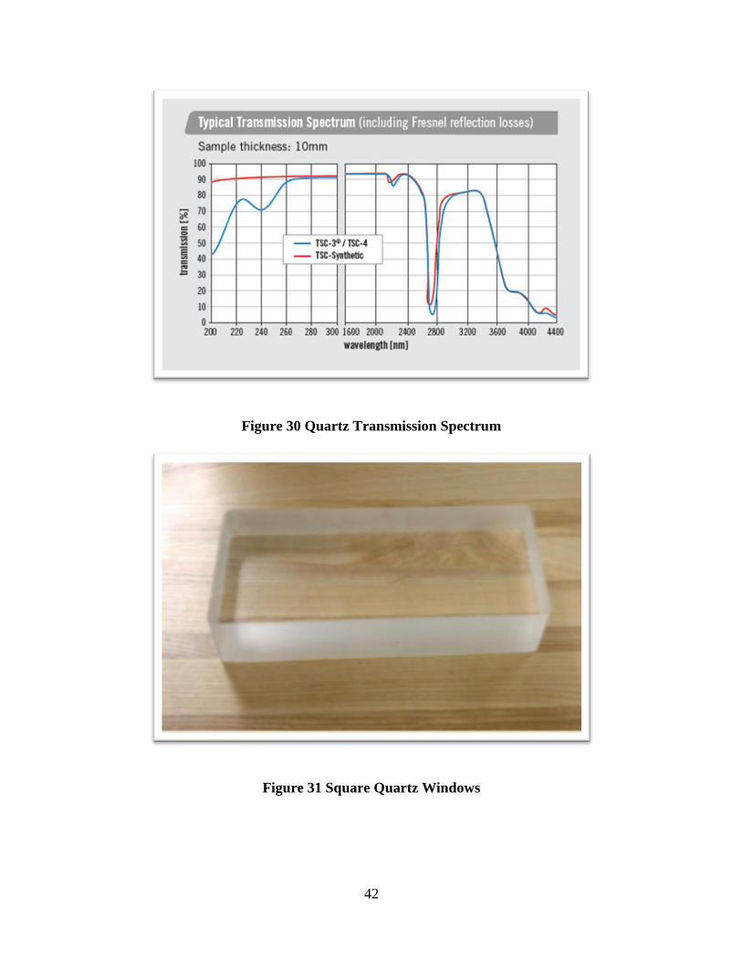
The quartz tube used has an outer diameter of 22.86 cm, inner diameter of 12.7 cm and a total
length of 63.5 cm. The use of three rectangular quartz windows is also incorporated with the
outer stainless steel chamber for visual based instrumentation. The quartz rectangular quartz
windows are 31.75 cm in length with 5.08 cm thickness and 10.16 cm width with a 6.35
millimeters circular grove on the four corners.
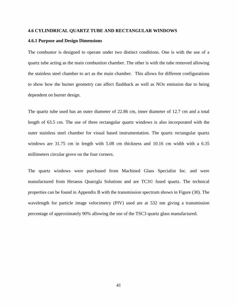
The quartz windows were purchased from Machined Glass Specialist Inc. and were
manufactured from Heraeus Quarzgla Solutions and are TC3© fused quartz. The technical
properties can be found in Appendix B with the transmission spectrum shown in Figure (30). The
wavelength for particle image velocimetry (PIV) used are at 532 nm giving a transmission
percentage of approximately 90% allowing the use of the TSC3 quartz glass manufactured.
42
Figure 30 Quartz Transmission Spectrum
Figure 31 Square Quartz Windows

43
Figure 32 Inner Quartz Tube
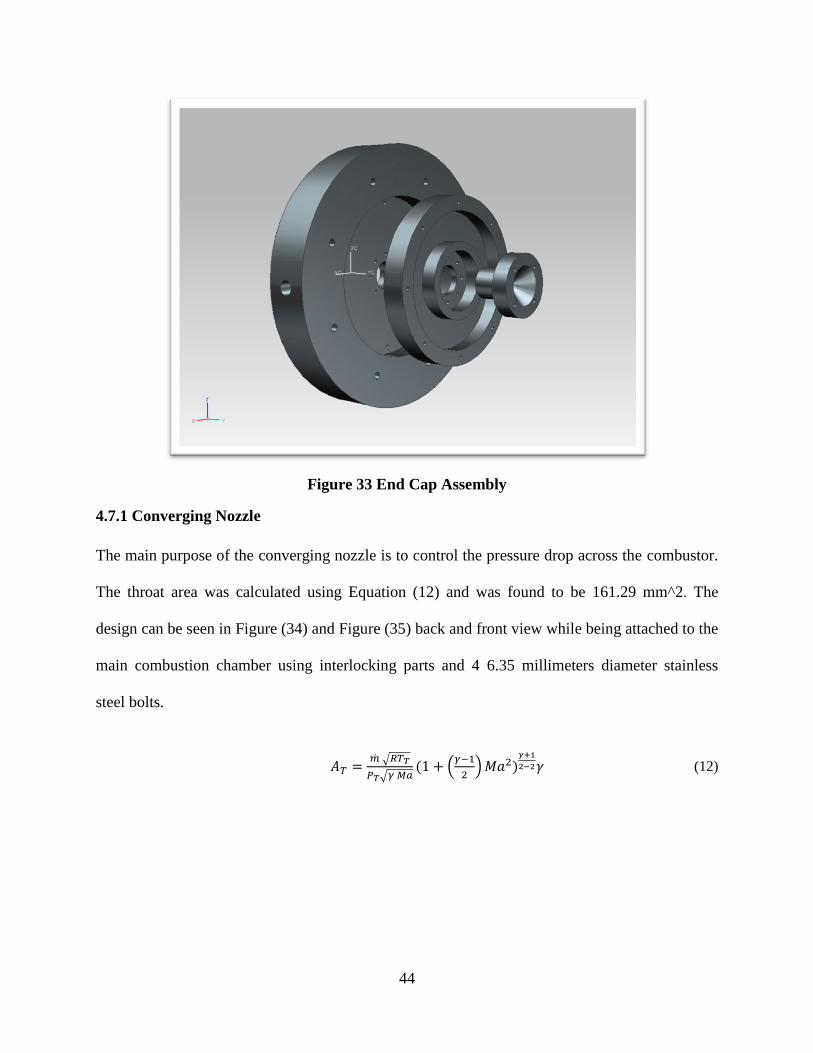
4.7 END CAP
The end cap is made of up of three removable modular sections. They include the converging
nozzle, the nitrogen exhaust disk, and the outer main cap that connects the end cap to the main
combustion chamber. The three part assembly is shown in Figure (33). Although the current
status the end cap is designed in a way that the listed design below can be manufactured to fit the
existing parts.
44
Figure 33 End Cap Assembly
4.7.1 Converging Nozzle
The main purpose of the converging nozzle is to control the pressure drop across the combustor.
The throat area was calculated using Equation (12) and was found to be 161.29 mm^2. The
design can be seen in Figure (34) and Figure (35) back and front view while being attached to the
main combustion chamber using interlocking parts and 4 6.35 millimeters diameter stainless
steel bolts.
√
√ ( (
) )
(12)

45
Figure 34 Exit Nozzel Bolt View
Figure 35 Exit Nozzle

46
4.7.2 Nitrogen Exhaust Disk
The nitrogen exhaust disk is needed when operating with the inner quartz tube configuration.
This disk will align with the end cap exhaust ports and allow nitrogen flow to exit through the
end cap. When the quartz tube is not in use and the nitrogen flow is not needed then it will
possible to replace the nitrogen exhaust disk to a solid circular piece that will block the fixed
nitrogen ports on the end cap. Both arrangements can be seen in Figure (36) and Figure (37).
The disk will be connected to the main end cap and CD nozzle through 6.35 millimeters diameter
stainless steel bolts that will run along the modular sections. The pressure created in the
combustor chamber and the use of grouping will also help in the sealing of the nitrogen exhaust
disk.
Figure 36 Nitrogen Exhaust Disk

47
Figure 37 Solid Disk When Operating Without Nitrogen Cooling Flow
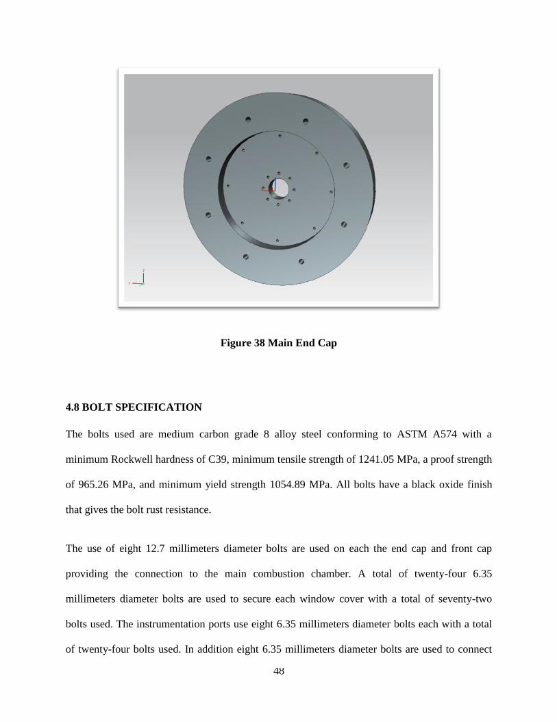
4.7.2 Main End Cap
The main end cap acts as a sealant to the main combustion chamber. It is also the link between
the combustion chamber and the exhaust. The outer dimension is 0.4572 meters with a hole with
a 50.8 millimeters diameter for the converging nozzle exhaust port. Also 16 ports for the
nitrogen exhaust ports of the cooling system of the inner combustor are also located on the end
cap. The end cap will be attached to the main combustor by 8 12.7 millimeters diameter stainless
steel bolts. The design set up is seen in Figure (38).
48
Figure 38 Main End Cap
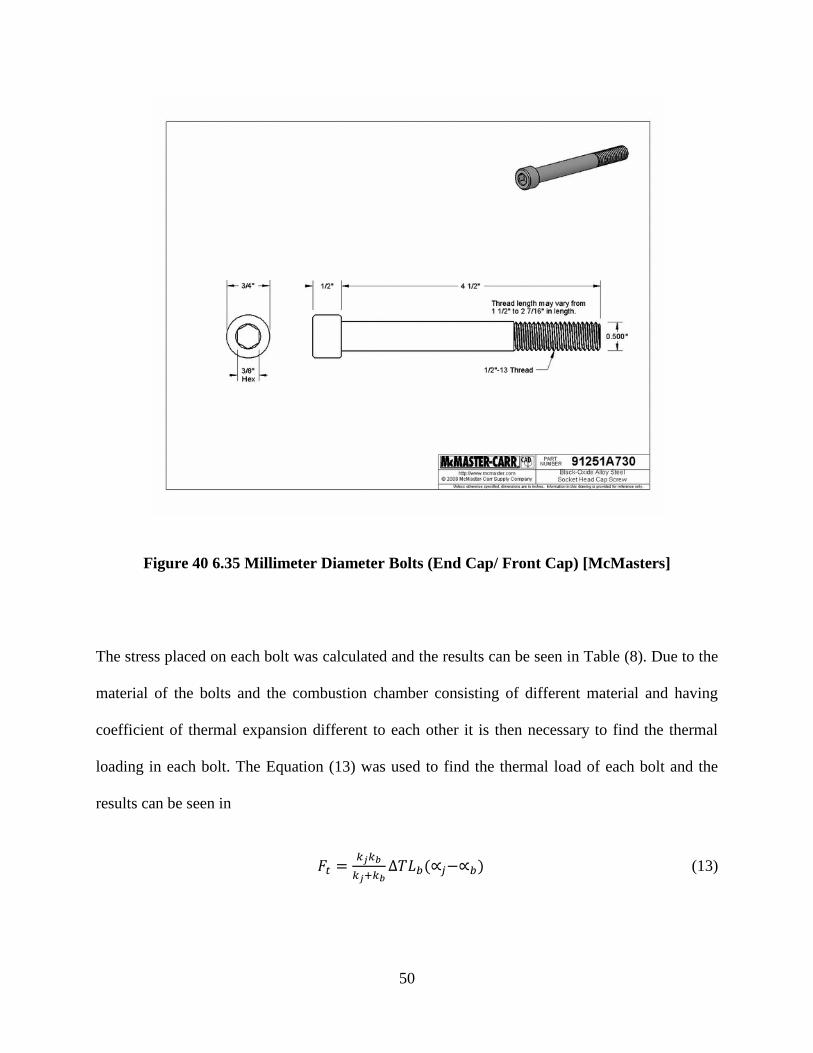
4.8 BOLT SPECIFICATION
The bolts used are medium carbon grade 8 alloy steel conforming to ASTM A574 with a
minimum Rockwell hardness of C39, minimum tensile strength of 1241.05 MPa, a proof strength
of 965.26 MPa, and minimum yield strength 1054.89 MPa. All bolts have a black oxide finish
that gives the bolt rust resistance.
The use of eight 12.7 millimeters diameter bolts are used on each the end cap and front cap
providing the connection to the main combustion chamber. A total of twenty-four 6.35
millimeters diameter bolts are used to secure each window cover with a total of seventy-two
bolts used. The instrumentation ports use eight 6.35 millimeters diameter bolts each with a total
of twenty-four bolts used. In addition eight 6.35 millimeters diameter bolts are used to connect

49
the exhaust and inlet manifold to the end cap and inlet cap respectively. The bolts were
purchased from MacMasters and CAD drawing with dimensions can be seen in Figure (39) for
the 12.7 millimeters diameter bolts and Figure (40) for the 6.35 millimeters diameter bolts.
Figure 39 12.7 Millimeter Diameter Bolt (Window Cover) [McMasters]
50
Figure 40 6.35 Millimeter Diameter Bolts (End Cap/ Front Cap) [McMasters]
The stress placed on each bolt was calculated and the results can be seen in Table (8). Due to the
material of the bolts and the combustion chamber consisting of different material and having
coefficient of thermal expansion different to each other it is then necessary to find the thermal
loading in each bolt. The Equation (13) was used to find the thermal load of each bolt and the
results can be seen in
( ) (13)

51
Table 6 Equation 11 Properties
Front Cap 12.7 mm
Bolt
End Cap 12.7 mm
Bolt
Window Cover
Bolts 6.35
k j
(350-300) K
The torque specification can be seen in Table (8) and were found using Equation (14)
( ) ( ) (14)
Table 7 Equation 12 Properties
Front Cap 12.7 mm
Bolt
End Cap 12.7 mm
Bolt
Window Cover
Bolts 6.35
Fp 11495.9 N 11495.9 N 2016 N

52
The overall stress of each bolt can be seen in Table (8) showing a maximum stress of 91.11 MPa
with a yield point of 1055 MPa for the End Cap and Front Cap Bolts.
Table 8 Bolt Stresses
Applicatio
n
Bolt Size Thermal
Load
Initial
Torque
Tensile
Stress
Yield
Stress
Safety
Factor
End Cap
Bolts
12.7
millimeters
diameter
.368 MPa 43.8 N m 90.75 MPa 1055 MPa 11.6
Front Cap
Bolts
12.7
millimeters
diameter
.368 MPa 43.8 N m 90.75 MPa 1055 MPa 11.6
Window
Cover
Bolts
6.35
millimeters
diameter
.936 MPa 3.84 N m 12.2 MPa 1055 MPa 80.3
Instrument
ation Port
Bolts
6.35
millimeters
diameter
.936 MPa .724 N m 64.5 MPa 1055 MPa 16.1
4.9 TEST MOUNTING
The main purpose of the test mounting facility is hold the combustor in place and prevent it from
moving due to the trust created from combustion. The use of Equation (15) (Hill and Peterson
1992) was used to determine the thrust created. With an overall thrust of 1966 N.
[( )( ) ] ( ) (15)

53
The use of three by 7.62 cm by 7.62 cm square tubing was used with an inner thickness of
9.52500 millimeters. The material used is A36 due to lost cost, availability, and meeting suitable
operating condition found in the FEA. The length and width is 0.8255 meters by 0.7112 meters
with the height being 0.7112 meters. The stand is composed of a two tier system with the
combustor being held in place by four curvature supports. Two if which connect the end cap and
front cap, using 19.05 millimeters diameter bolts, due to the thrust created by the combustor
outlet nozzle. The use of removable wheels is used to position the combustor in place and
dampers attached to the floor will be used when the combustor is operational. The combustor
will be mounted using a two eye bolts attached to the top of the end cap and front cap and a lift
will be used to position the combustor in place. The design of the mounting can be seen in Figure
40 while the curvatures used to attach the combustor can be seen in Figure 40.
Figure 41 Test Stand and Combustor

54
Figure 42 Attachment Curvature
4.10 GASKETS
Gaskets are used throughout the assembly to prevent leaks and in place of any metal to metal or
quartz to metal contact. The use of Unifrax high temperature 1600 paper are used with the
complete technical properties listed in Appendix D. The maximum use temperature is given as
1873 Kelvin with a maximum shrinkage of 4 %. The paper is made of high purity crystalline
alumina fiber stabilized by small amounts of silica providing chemical and thermal stability.
[Unifrax].
4.11 MANUFACTURING
After the completed design of the combustor was finalized the manufacturing stage of the project
was undertaken. Currently the manufacturing of the presented design continues to be a working

55
project and ongoing work is needed to make the combustor operational. The current status of the
combustor includes the completion of the inlet manifold and testing stand. Also the main
chamber has been manufactured and assemble to allow testing using the stainless steel as the
main combustion chamber. The current completed manufactured parts can be seen in the Figure
14 and show the inlet manifold, end cap, main chamber, window covers, instrumentation covers,
front cap, and testing stand assembled and in its current state. A pressure test has also been
conducted to check for any leaks in the combustor.

56
5. Summary and Conclusions
5.1 CONCLUSION
The main objective of this project was to design an optically accessible high pressure combustor.
The following steps were conducted to design and develop the combustor. The adiabatic flame
temperature was determined. The wall temperature was found as a function of time and the
needed flow rate of and was calculated to maintain the combustor at a safe operable
condition. Finite element analysis was conducted on the combustion chamber and included the
front cap, main chamber, quartz tube, window covers, quartz windows, and end cap. The design
stages of the combustor were also covered and the design description and purpose of each
individual component was included. The stress analysis of the bolts was conducted and the FEA
and description of the testing stand was also covered.
5.2 FUTURE WORK
The modular design of the combustor incorporates two different testing capabilities. One was the
use of a quartz tube acting as the main combustion chamber the other is the removal of the quartz
tube and allowing the stainless steel to act as the main chamber. Due to time and cost restraints at
this point the combustor can be used only using the latter configuration. If the quartz tube
configuration is needed the end cap and front cap can be machined to allow for this assembly.
The manufacturing of the nitrogen distributor and end cap nitrogen disk would also be needed
for the cooling necessary when using the quartz tube as the main chamber. Also the purchasing
of the quartz tube would be necessary.
Before testing the cooling system will need to be implemented. The use of copper cooling coils
as shown in Figure (13) would be necessary while the water flow rate needed to cool the
57
combustor to safe operating conditions can be found in Chapter 3. The need to develop the
ignition system will also be needed and the control systems necessary to control the fuel/air,
water, nitrogen, and methane will also need to be completed.
5.3 FUTURE TESTING
Once the combustor is completed it would then be possible to conduct experiments to analyze
the flame characteristics using a high speed PIV system to determine the effects of fuel
composition on flame characteristics particularly in realistic turbine conditions.

58
Reference
. "AZOM." Stainless Steel 410. N.p., 2012. Web. 1 Apr 2012
<http://www.azom.com/article.aspx?ArticleID=970>.
Bidhan, Gildberto , Corona K. Dam, et al. "An Experimental Investigation of Combustion
Induced Vortex Breakdown Flashback in a Swirl Stabilized Burner." AIAA. (2011): n.
page. Print.
Budynas, Richard. Shigley's mechanical engineering design. Boston: McGraw-Hill, 2008
Compilation of Air Pollutant Emission Factors, AP 42 Volume 1, Fifth Edition, Chapter 3:
Stationary Internal Combustion Sources, Section 3.1 Stationary Gas Turbines EPA,
Washington DC, April 2000
Department of Engineering Combustion for gas turbines. "High Pressure Combustion Facility."
Editorial. Combustion for Gas Turbines. Department of Engineering , 2009. Web. 25 Feb.
2012.<http://www-g.eng.cam.ac.uk/gtcombustion/facilities/index-facilities.html>.
Heraeus, . "TSC Series." . N.p., 02/2009. Web. 2/2012. <www.base-materials.heraeus-
quarzglas.com>.
Hill, Philip. Mechanics and thermodynamics of propulsion. Reading, Mass: Addison-Wesley,
1992.
H.J. Tomezak, G. Benelli, L Carrai, D. Cecchini “Investigation of a Gas Turbine Combustor
Sytem Fired With Mixtures of Natural Gas and Hydrogen”,
IRVIN, . "UCI COmbustion Laboratory." . N.p., 9/2010. Web. 27 Apr 2012.
<http://www.ucicl.uci.edu/2/default.asp&xgt;.\
J.H. Frank, M. F. Miller, M G. Allen “Imaging of Laser-Induced Fluorescence in a High Pressure

59
Combustor” Physical Science Inc.
J. Sato, K. Konishi, H. Okada, T. Niioka, “Ignition Process of Fuel Spray Injected into High
Pressure High Temperature Atmosphere” ,Vol-21, 1988, Symposium (International) On
Combustion ,p-695-702
MATWEB." Material Property Data. N.p., 12/2009. Web. 1 Apr 2012.
<http://www.matweb.com/search
National Energy Technology Laboratory
http://www.netl.doe.gov/onsite_research/Facilities/high-pressure.html
Pennsylvania State University, . "Description of PSU’s High Pressure Combustion Lab
Capabilities and Projects." . Chemical Propulsion Information Center, n.d. Web. 25 Apr
2012.<http://www.google.com/url?sa=t&rct=j&q=&esrc=s&source=web&cd=2&ved=0
CCoQFjAB&url=http://www.hpcl.psu.edu/_notes/CPIAC%20Bulletin.doc&ei=vl2YT_jp
KcWL2AWs4M2QBw&usg=AFQjCNGqGNkiMQZjHQQsgj-
qIJqQu53jkw&sig2=ie6sdgSSZnQElcI4IMC_zA>.
. "Roymech." Bolt Preloading. N.p., 12/2009. Web. 1 Apr 2012.
<http://www.roymech.co.uk/Useful_Tables/Screws/Preloading.html>.
S.Daniele, P,.Jansohn, K.Boulouchos, “Experimental investigation of lean premixed syngas
combustion at gas turbine relevant conditions :lean blow out limits, emissions and
turbulent flame speed ”,ASME Turbo Expo,2010.
"The World’s First Industrial Gas Turbine Set ." . ASME, 07/1988. Web. 01/2012.
60
<http://www.pdfdownload.org/pdf2html/view_online.php?url=http://files.asme.org/asme
org/Communities/History/Landmarks/12281.pdf>.
Tse.S.D., Zhu.D,LaW.C.K, “Optically accessible high-pressure combustion apparatus”,
American Institute of Physics.2004
. "Unifrax." 1600 Paper. N.p., 2008. Web. 1 Apr
2012.<http://www.unifrax.com/web/Audit.nsf/ByUNID/B6AA44CDAD87F72F852579E
E0004EA80/$File/1600 Paper EN.pdf>.
US. Department of Energy. Coal Our Most Abundant Fuel". 2011. Web.
<http://fossil.energy.gov/education/energylessons/coal/gen_coal.html>.
"
.
61
Appendix
A. ADIABATIC FLAME TEMPERATURE
Table 9 Heat of Formation at 298 K (kJ/kmol)
CO -110541
H2 0
O2 0
N2 0
C02 -393546
H20 -241845
CO -110541
Table 10 Specific Heat 2415 K (kJ/kmol-k)
CO2 61.402
H20 53.511
N2 36.558
CO2 61.402
( )
Assuming a steady flow process with no work done to the system and adiabatic conditions
HP=HR.
First step is to solve for HR using Equation (14). After HR is found and by assuming an adiabatic
temperature the Cp (Specific Heat) of CO2, H2O, and N2 can be calculated. Using the resulting

62
adiabatic temperatures and the Cp given it is then possible to plug it into Equation (15) to solve
for HP. This procedure is then repeated until HP=HR giving the adiabatic temperature.
( ) ( ) (( ) ( ) ) (14)
(( ) ( )) (( )
( )) ( ( ) ( )) (15)
( )
( ) ( )

63
B. QUARTZ MATERIAL PROPERTIES (Heraeus 2009)

64
C. CURRENT PART DRAFTINGS

65

66

67
D. GASKET (Unifrax)

68
E. COOLING CALCULATIONS
H20 Ice Water Total Heat Removed 388.32 KW
Cp 4.19 KJ/Kg K
Boiling Point 370 K
DT 77.00 K 350-273
Mass Flow Rate 1.20 Kg/S
Mass Flow Rate 1.20 Kg/s 1 Liter= 1 Kg 1.20 L/s 1Liter=.26417 Gallon 0.32 Gallons/s
19.09 Gallons/m
1145.60 Gallons/Hour
Ethylene glycol 100% Total Heat Removed 388.32 KW
Cp 2.80 KJ/Kg K Boiling Point 470
DT 77.00 K 350-273 K
Mass Flow Rate 1.80 Kg/S Mass Flow Rate 1.80 Kg/s Kg=Lt 1.62 L/s 1Liter=.26417 Gallon 0.43 Gallons/s
25.72 Gallons/m
1543.14 Gallons/Hour
Ethylene glycol 30% Total Heat Removed 388.32 KW
Cp 3.33 KJ/Kg K DT 77.00 K
Mass Flow Rate 1.52 Kg/S Boiling Point 377
350-273 K
Mass Flow Rate 1.52 Kg/s Kg=Lt 1.37 L/s 1Liter=.26417 Gallon 0.36 Gallons/s
21.66 Gallons/m
1299.48 Gallons/Hour

69
Assuming atmospheric conditions in tank and exit. is assumed to be approximate zero.
Q=Volumetric Flow Rate 0.001 m^3/s Mass Flow Rate 1.210 Kg/s Density 998.200 Kg/m^3 Length 10.000 m Pipe Diameter 0.038 m Area 1.5 in Pipe 0.001 m^2 Velocity 1.5 in 1.063 m/s Area 0.000 m^2 Velocity .25 in 0.957 m/s Assuming 40 Line Distribution Around Combustion Chamber
(.25) V^2/2g 0.047 m (1.5 in) V^2/2g 0.058 m Z2 1.200 m Z1 0.000 m Entrance Loss H1 0.029 m Assuming Square Edge K=.5
Friction Line H2 1.5 in D 0.318 m f Friction Factor=.021
Friction Line H3 .25 in D 0.711 m f friction factor=.029
Valve Loss H4 0.412 m Assuming Glove Valve K=340*f Flow Through Branch H5 6.499 m Flow Through Branch K=60* f 80 total
90 Elbow H6 0.145 m Elbow K=30*f 4 total
Exit loss H7 0.058 m K=1
Total Head Loss HA 9.371 m
30.736 Ft
y 9792.342

70
Power of Pump 145.368 W
0.195 HP
71
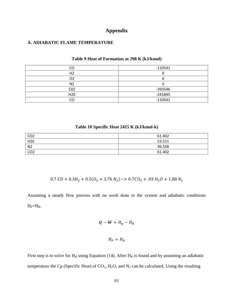
F. FLUENT ANALYSIS
Temperature: Outlet View
Simulation of the Flow Field of Water over the Stainless Steel Chamber
Assuming the Use of a Cooling Jacket
Mass Flow Rate 1.21 Kg/s
Max Temperature= 525 K
Constant Heat Flux= 897 W/m^2
500 KW
Inlet View
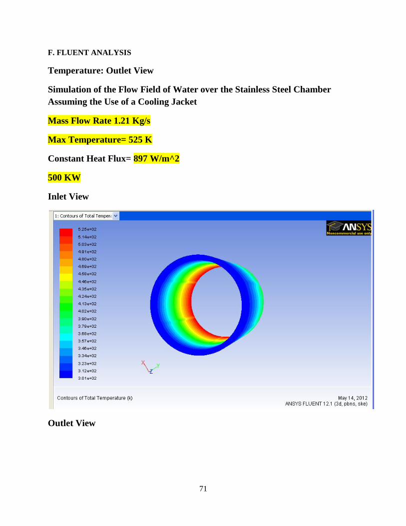
Outlet View
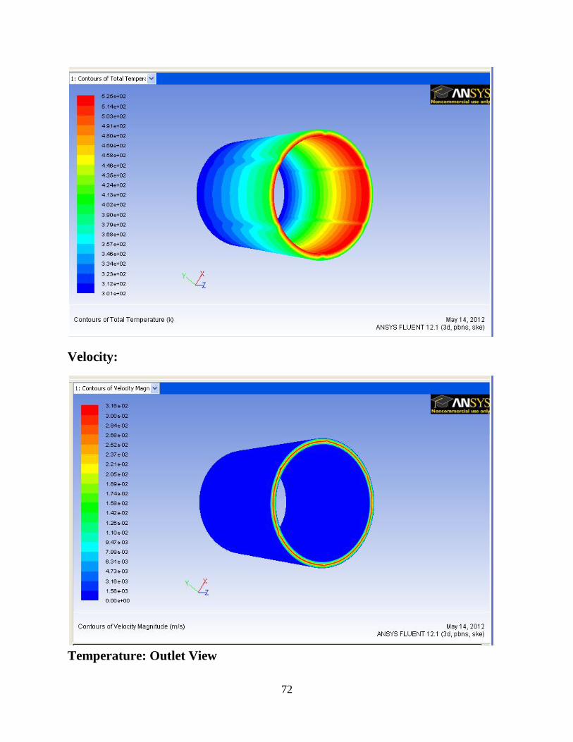
72
Velocity:
Temperature: Outlet View
73
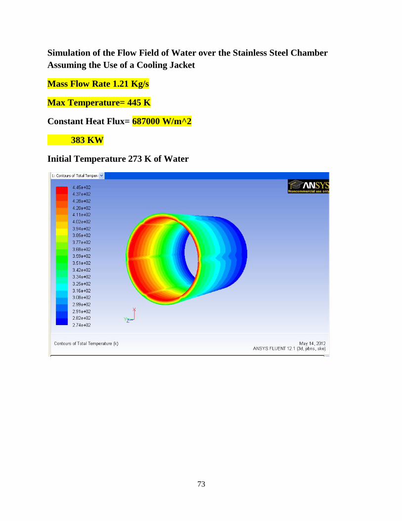
Simulation of the Flow Field of Water over the Stainless Steel Chamber
Assuming the Use of a Cooling Jacket
Mass Flow Rate 1.21 Kg/s
Max Temperature= 445 K
Constant Heat Flux= 687000 W/m^2
383 KW
Initial Temperature 273 K of Water

74
75
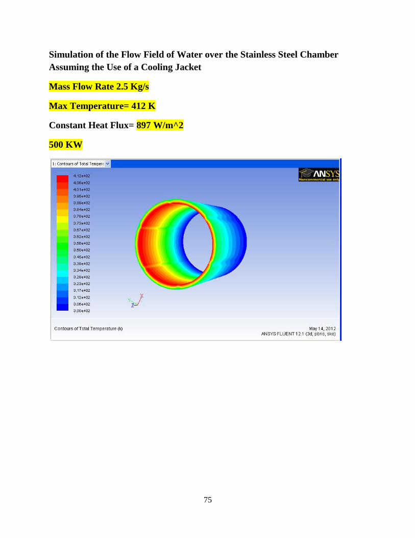
Simulation of the Flow Field of Water over the Stainless Steel Chamber
Assuming the Use of a Cooling Jacket
Mass Flow Rate 2.5 Kg/s
Max Temperature= 412 K
Constant Heat Flux= 897 W/m^2
500 KW
76
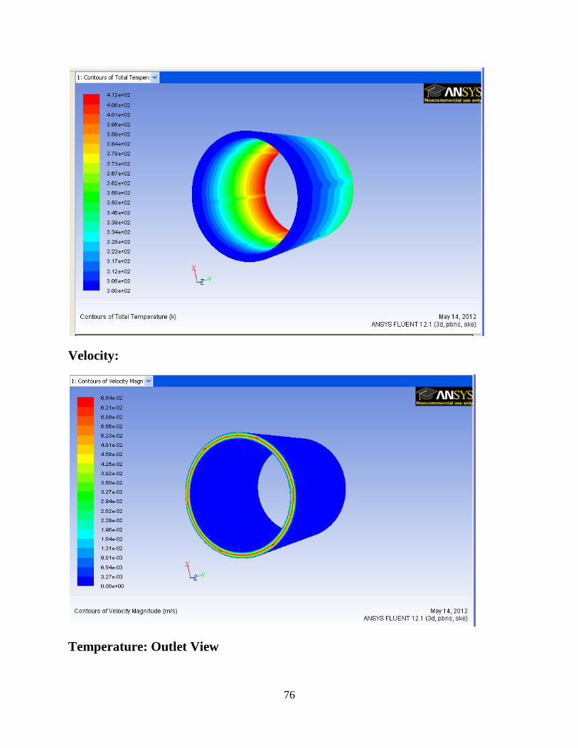
Velocity:
Temperature: Outlet View
77
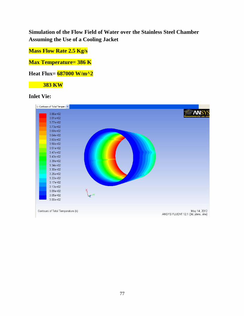
Simulation of the Flow Field of Water over the Stainless Steel Chamber
Assuming the Use of a Cooling Jacket
Mass Flow Rate 2.5 Kg/s
Max Temperature= 386 K
Heat Flux= 687000 W/m^2
383 KW
Inlet Vie:

78
Velocity:
79
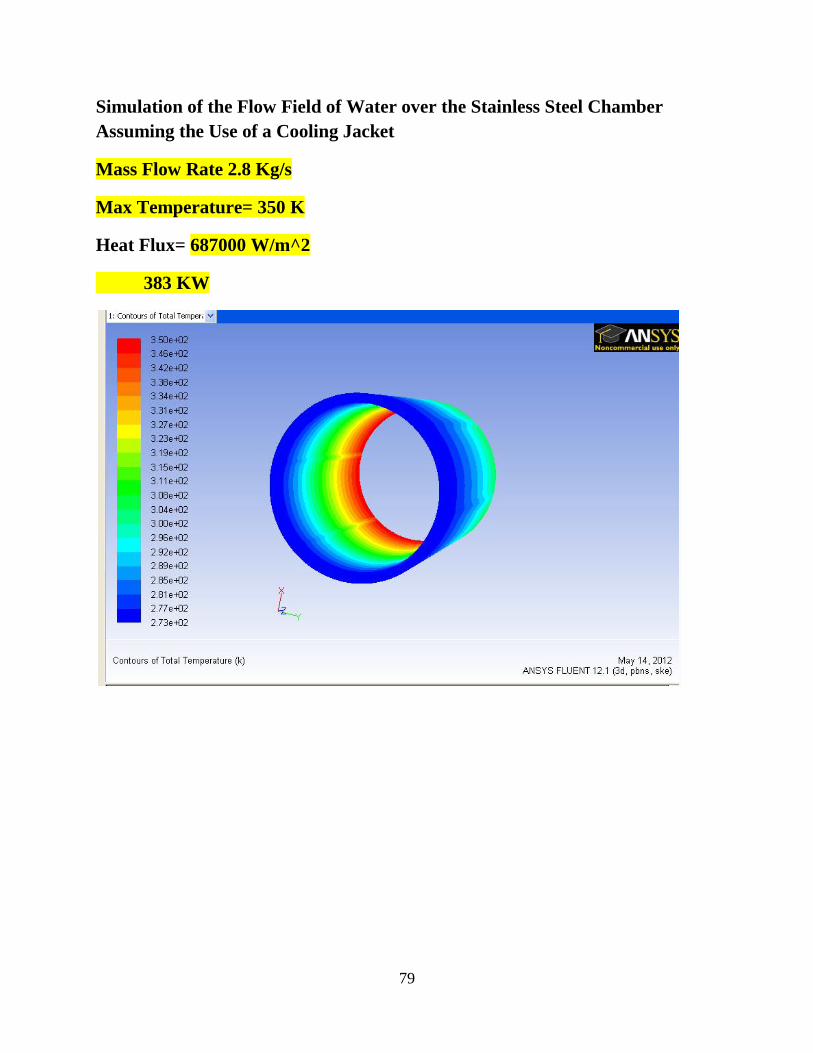
Simulation of the Flow Field of Water over the Stainless Steel Chamber
Assuming the Use of a Cooling Jacket
Mass Flow Rate 2.8 Kg/s
Max Temperature= 350 K
Heat Flux= 687000 W/m^2
383 KW

80

81
Vita
Mr. Jesus Nunez Michel is a researcher at the Center of Space Exploration and Technology
Research cSERT (Combustion and Propulsion Lab) located at the University of Texas at El Paso.
He received his Bachelors of Science in Mechanical Engineering at the University of Texas at El
Paso in the Spring of 2010
Permanent address: 1458 Jim Larabel
El Paso, Texas, 79936
This thesis/dissertation was typed by Jesus Nunez