design and development on electro …mechanical.srpec.org.in/files/project/2016/27.pdfdesign and...
TRANSCRIPT

DESIGN AND DEVELOPMENT ON ELECTRO MAGNETIC AND AUTOMATIC BREAKING SYSTEM
GUIDED BY :- PROF. MANOJ P . RAJPARA
PREPARED BY: GROUP NO:-27
RAJPUT VIPUL 11ME64
PARAJAPATI NIKUL 12ME02
MODI SAGAR 12ME17
DARJI MILAN 12 ME18
CONTENT
IntroductionProject PrincipalLiterature ReviewTypes of brakeComponent Component designConstruction
Future Scope
AdvantageDisadvantageApplicationWork PlanningReference

INTRODUCTION
In this project we have designed and establishment and
Electromagnetic disk braking system so as to have a future
alternative to traditional breaking systems. Electromagnetic disk
braking system slows an objects by creating an eddy current
through electromagnetic induction which create resistance. When
electromagnetic are used, control of the breaking action is made
possible by varying the strength of the magnetic field of the
electromagnets creates eddy currents in the discs. These eddy
currents generate an opposing magnetic field (Lenz's law), which
then resists the rotation of the discs, providing braking force. The
net result is to convert the motion of the rotors into heat in the
rotors.

Electro magnetic and auto breaking
system
designed to develop a new system that can solve thisproblem where drivers may not brake manually but thevehicles can stop automatically due to obstacles. Thisproject is about a system that can control braking systemfor safety. Using ultrasonic as a ranging sensor, itsfunction based on ultrasonic wave. After transmit bytransmitter, the wave can reflect when obstacle detectedand receive by receiver. The main target for this project is,car cans automatically braking due to obstacles when thesensor senses the obstacles. The braking circuit functionis to brake the car automatically after received signalfrom the sensor.

PRINCIPLE
As the disc enters the magnetic field a series of eddy currents will
be produced (as explained by Lenz‟s law). This produces a
magnetic field that will oppose the change brought about by the
rotating disc. If the magnetic field of the horseshoe magnet is
coming out of the page then the induced magnetic field will be
into the page. The induced current will be in a clockwise direction
to produce this field. This will bring the disc to a halt very quickly
and will result in a small amount of heat being produced by the
eddy currents.

PRINCIPLE

PRINCIPLE
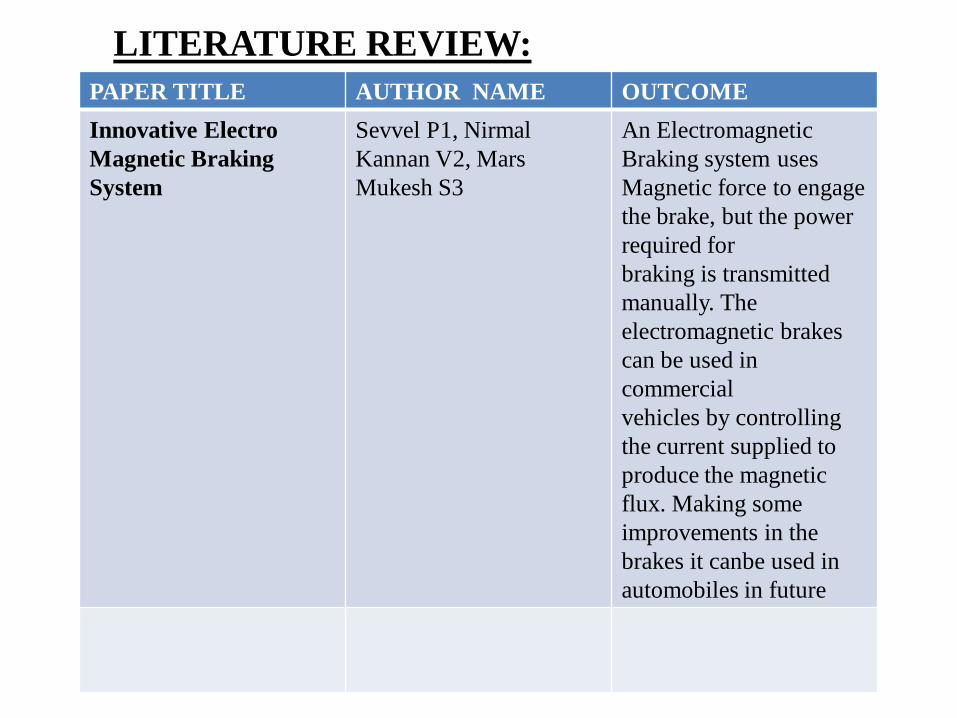
PAPER TITLE AUTHOR NAME OUTCOME
Innovative Electro
Magnetic Braking
System
Sevvel P1, Nirmal
Kannan V2, Mars
Mukesh S3
An Electromagnetic
Braking system uses
Magnetic force to engage
the brake, but the power
required for
braking is transmitted
manually. The
electromagnetic brakes
can be used in
commercial
vehicles by controlling
the current supplied to
produce the magnetic
flux. Making some
improvements in the
brakes it canbe used in
automobiles in future
LITERATURE REVIEW:

PAPER TITLE AUTHOR NAME OUTCOME
ULTRASONIC CAR
BRAKING SYSTEM
ULTRASONIC CAR BRAKING SYSTEM MOHD SHAHRIZAN B. SAHRI
An ultrasonic car braking system includes; an ultrasonic wave emitter provided in a front portion of an automatic brakingcar producing and emitting ultrasonic waves frontward in a predetermined distance in front of the car.

PAPER TITLE AUTHOR NAME OUTCOME
Fabrication of Auto-Braking System for Pre-Crash Safety Using Sensor
Eung Soo Kim This module can detect the distance between front vehicle and driver’s vehicle to keep a constant distance using a sensor and operate the brake system forcibly if the driver does not decrease the speed of car.

PAPER TITLE AUTHOR NAME OUTCOME
ANTILOCK BRAKING SYSTEM
Sahil Jitesh1* ABS generallyoffer advanced vehicle control and minimize the stopping distance in slippery and dry surface,conversely on loose surface like gravel or snow covered pavement, ABS can significantly increasebraking distance, although still improving vehicle control.

TYPES OF BRAKE
DRUM BRAKE:
It consists of a brake drum which is concentric to the axle
hub whereas on the axle casing is mounted a back plate. The
back plate is made up of pressed steel sheet and it provides
support for the expander, anchor and brake shoes.

DISC BRAKE:
Disc brakes work using the same basic principle as the brakes
on a bicycle as the caliper pinches the wheel with pads on both
sides, it slows the vehicle.

AIR BRAKE :
Air brakes use standard hydraulic brake system components such
as braking lines, wheel cylinders and a slave cylinder similar to a
master cylinder to transmit the air-pressure-produced braking energy
to the wheel brakes. Air brakes are used frequently when greater
braking capacity is required.

HAND BRAKE :
Hand brakes are the parking or emergency brakes. They helps a
vehicle to park on a slope or during emergencies when primary
brakes are disabled. They works independently of primary brakes.
COMPONENTS USED
• DC motor (as engine)
• DC electromagnets
• Chain
• Pedals
• Relay
• Transformer
• Ultrasonic sensor

COMPONENT
1.DISC
The brake disc is the component of a
disc brake against which the brake
pads are applied. The material is
typically grey iron a form of cast
iron. The design of the disc varies
somewhat. Some are simply solid,
but others are hollowed out with fins
or vanes joining together the disc's
two contact surfaces (usually
included as part of a casting
process)..
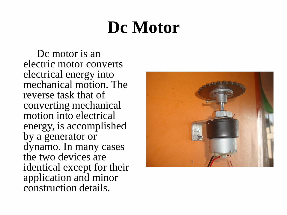
Dc Motor
Dc motor is an electric motor converts electrical energy into mechanical motion. The reverse task that of converting mechanical motion into electrical energy, is accomplished by a generator or dynamo. In many cases the two devices are identical except for their application and minor construction details.

Transformer
An electric current flowing in a
wire creates a magnetic field
around the wire (see drawing
below). To concentrate the
magnetic field, in an
electromagnet the wire is wound
into a coil, with many turns of
wire lying side by side. The
magnetic field of all the turns of
wire passes through the center of
the coil, creating a strong
magnetic field there.

ElectromagnetElectromagnets are very widely used in electric and
electromechanical devices, including:
Motors and generators
• transformers
Relays, including reed relays originally used in telephone
exchanges
• Electric bells
• Loudspeakers
Magnetic recording and data storage equipment: tape recorders,
VCRs, hard disks
Scientific instruments such as MRI machines and mass
spectrometers
Particle accelerators

chain
A chain drive is a mechanism
for transferring mechanical
powerbetw two places, and is
common means of locomotion in
bicycles and motorcycles. It is
alsmotive source for many
different types ofmachinery.
Chain drives have existed as a
technology sinc. he third
century BC and have remained he
same in their basic design since
that time.

INFRARED PROXIMITY SENSOR
An infrared proximity sensor is a sensor
able to detect the presence of nearby objects
without any physical contact. A infrared
proximity sensor often emits an
electromagnetic field or a beam of
electromagnetic radition in(frared, for
instance), and looks for changes in the field
or return signal. The object being sensed is
often referred to as the infrared proximity
sensor's target. Different infrared proximity
sensor targets demand different sensors. For
example, a capacitive photoelectric
sensormight be suitable for a plastic target;
an inductiveinfrared proximity sensor always
requires a metal target.

LCD
A liquid-crystal display better known as (LCD) is a flat panaldisplay,electronic visual display or video displaythat uses the light modulating properties of liquid crystals. Liquid crystals do not emit light directly.
LCDs are used in a wide range of applications including computer monitors, televisions, instrument panels,aircraft cockpit displays, and signage. They are common in consumer devices such as video players, gaming devices, clocks, watches. calculators, and telephones, and have replaced cathode ray tube (CRT) displays in most applications.
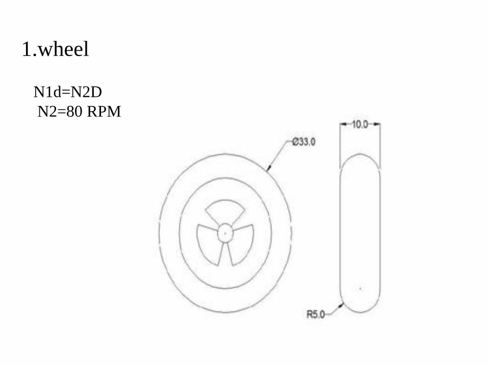
1.wheel
N1d=N2D
N2=80 RPM

2.disc
Centre distance between the pulleys= 32cm
Diameter of the driving pulley = 4.4cm=d
Diameter of the driven pulley = 5.5cm=D Speed
of the driving pulley = 100 rpm=N1

3.electromagnet
24volt

4.Wood bar

3-D Modeal

WORKING MODEAL

Sr.No PARTS COST1. Chain 350
2. wheel 450
3. motor 225
4. switch 110
5. Transformer 3 –Amp 180
6. Micro control Board 1000
7. LCD Display 180
8. Micro controller I.C 70
9. Wooden board 250
10. Wiring cost 150
11. Bolt & nut 150
Project cost

Sr. No PARTS COST
13. sensor 400
14. Main cable 20
Total Cost 3635

CONSTRUCTION
A horseshoe magnet (A-1) has a North and South Pole. If a
piece of Iron contacts both poles, a magnetic circuit is created.
In an electromagnetic brake, the North and South Pole is
created by a coil shell and a wound coil. In a brake, the
armature is being pulled against the brake field. (A-3) The
frictional contact, which is being controlled by the strength of
the magnetic field, is what causes the rotational motion to stop.
All of the torque comes from the magnetic attraction and
coefficient of friction between the steel of the armature and the
steel of the brake field. Example, if the brake was required to
have an extended time to stop or slip time, a low coefficient
material can be used.

FUTURE SCOPE
A revolutionary invention is made in the field of
brakes. The Electromagnetic brakes are excellent
replacement for conventional automobile brakes. The use
of Electromagnetic brakes can be done for lighter vehicles
also. With some modification, a regenerative braking
system can be equipped with the Electromagnetic brakes.
The Electromagnetic brakes are the future of automobile
brakes.

CONCLUSION
The prototype work “VEHICLE SPEED CONTROL AND
AUTOMATIC BRAKING SYSTEM” has been successfully
designed and tested. Integrating features of all the components
have used developed it .Presence of every module has been
reasoned out and placed carefully thus contributing the best
working of the unit. Secondly using highly advanced IC‟s and
with the help of growing technology the project has been
implemented successfully
Electromagnetic brakes can be used for modern Light as
well as heavy vehicles. They give better performance with
enhanced safety.
APPLICATION
• Commercial vehicle
• Building lift
• Industries machine
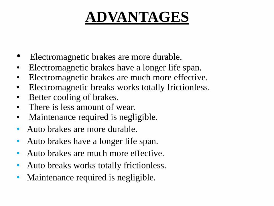
ADVANTAGES
• Electromagnetic brakes are more durable.
• Electromagnetic brakes have a longer life span.• Electromagnetic brakes are much more effective.• Electromagnetic breaks works totally frictionless.• Better cooling of brakes.• There is less amount of wear.• Maintenance required is negligible.
• Auto brakes are more durable.
• Auto brakes have a longer life span.
• Auto brakes are much more effective.
• Auto breaks works totally frictionless.
• Maintenance required is negligible.

DISADVANTAGES
• Battery low this time is not working
• Electronic Control Module in side fault that time break not
working
• A special spring mechanism needs to be provided for the quick
return of the brake shoe.
• Dependence on battery power to energize the brake system
drains down the battery much faster.
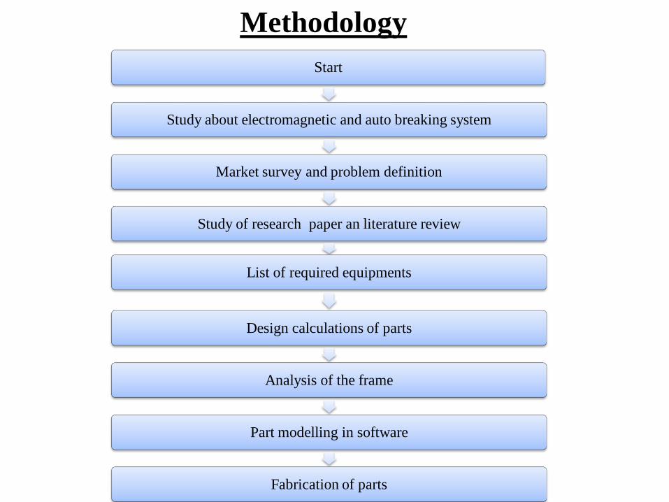
Methodology
Start
Study about electromagnetic and auto breaking system
Market survey and problem definition
Study of research paper an literature review
List of required equipments
Design calculations of parts
Analysis of the frame
Part modelling in software
Fabrication of parts

Reference
1. H. Van Oostveen and R. Siezen, “ErfahrungenmitPermanentmag-net-
Schienenbremsen”, GlasersAnnalen, Nr 12, S. 613-617, 1997.
2. Biro, O. and Preis, K., „„Finite element analysis of 3-D eddy current,‟‟
IEEE Transactions onMagnetics, Vol. 26, No. 2, pp. 418–423, Mar, 1990.
3. Ohyma, T., „„Adhesion at higher speeds, its basic characteristic, its
improvement and somerelated problem,‟‟ Japanese Railway Engineering,
Vol. 108, 1988.
4. A B Sharkawy (2010), “Genetic FuzzySelf-tuning PID Controllers for
Antilock
Braking Systems” EngineeringApplications of Artificial Intelligence, Vol.
23, pp. 1041-1052.
5. A Poursamad (2009), “AdaptiveFeedback Linearization Control ofAntilock
Bracking System Using NeuralNetworks”, Mechatronics, Vol. 19, pp.
767-773.

Thank You