design and evaluation of an ieee 802.11 based dual mac …sri/students/satyajit-thesis.pdf ·...
TRANSCRIPT

Design and Evaluation of an IEEE 802.11 BasedDual MAC for MANETs
Dissertation
submitted in partial fulfillment of the requirementsfor the degree of
Master of Technology
by
Satyajit Rai
Roll No: 01329009
under the guidance of
Prof. Sridhar Iyer
and
Dr. Leena Chandran Wadia
aKanwal Rekhi School of Information Technology
Indian Institute of Technology, BombayMumbai - 400076.
2003

Dedicated tomy mother
Smt. Manorama Rai
andmy father
Shri Harishchandra Rai
Dissertation Approval Sheet
This is to certify that the dissertation titled
Design and Evaluation of an IEEE 802.11 Based Dual MAC for MANETs
By
Satyajit Rai(01329009)
is approved for the degree of Master of Technology.
Prof. Sridhar Iyer(Guide)
Dr. Leena Chandran Wadia(Co-Guide)
Internal Examiner
External Examiner
Chairperson
Date :
Abstract
Multihop ad-hoc wireless networks offer great challenges for protocol designers. Stationsin such networks are constrained by factors like low power, limited bandwidth, linkerrors, and collisions. Changes are needed at various levels of the protocol stack, mostimportantly at the medium access layer (MAC). The medium access mechanism inmultihop wireless networks should minimize collisions, and take care of the hidden andexposed node problems. The IEEE 802.11 MAC with Distributed Coordination Function(DCF) does not scale well in such networks. We introduce Point Coordination Function(PCF) in the region of high traffic areas, and discuss its effect on network performance.To improve network scalability and throughput, we propose the design of a new MACcalled Dual MAC. This work discusses architecture and working of the dual MAC indetail. Performance results of the network using dual MAC are presented, and comparedwith that of pure DCF operation.
iv

Acknowledgments
I express my sincere gratitude towards my guides Prof. Sridhar Iyer and Dr. LeenaChandran Wadia for their constant help, encouragement and inspiration throughoutthe project work. Without their invaluable guidance, this work would never have beena successful one. I would also like to thank the members of the Mobile ComputingResearch Group at KReSIT, namely Srinath Perur, Vijay Rajsinghania, Vikram Jamwal,Deepanshu Shukla, Anupam Goyal, and Abhishek Goliya for their valuable suggestionsand helpful discussions. Last, but not the least, I would like to thank the whole KReSITfamily which made my stay at IIT Bombay a memorable one.
Satyajit RaiIIT BombayJanuary 15, 2003
v

Contents
Abstract iv
Acknowledgments v
List of Figures viii
1 Introduction: Cooperative Ad-Hoc Networks 11.1 Introduction to Wireless Ad Hoc Networks . . . . . . . . . . . . . . . . 11.2 Multi-hop Wireless Networks . . . . . . . . . . . . . . . . . . . . . . . . 11.3 Problems with Centralized Traffic . . . . . . . . . . . . . . . . . . . . . . 21.4 Requirements and Challenges of Multi-hop Wireless Networks . . . . . . 2
1.4.1 IP and Routing . . . . . . . . . . . . . . . . . . . . . . . . . . . . 21.4.2 MAC . . . . . . . . . . . . . . . . . . . . . . . . . . . . . . . . . 31.4.3 Physical: Hidden and Exposed Node Problems . . . . . . . . . . 3
1.5 Thesis Objective and Scope . . . . . . . . . . . . . . . . . . . . . . . . . 41.6 Thesis Outline . . . . . . . . . . . . . . . . . . . . . . . . . . . . . . . . 4
2 MAC in Multi-hop Ad-Hoc Networks 52.1 Channel Access Mechanisms . . . . . . . . . . . . . . . . . . . . . . . . . 5
2.1.1 TDMA . . . . . . . . . . . . . . . . . . . . . . . . . . . . . . . . 52.1.2 CSMA/CA . . . . . . . . . . . . . . . . . . . . . . . . . . . . . . 62.1.3 Polling MAC . . . . . . . . . . . . . . . . . . . . . . . . . . . . . 6
2.2 Available MACs . . . . . . . . . . . . . . . . . . . . . . . . . . . . . . . 72.2.1 IEEE 802.11 MAC . . . . . . . . . . . . . . . . . . . . . . . . . . 72.2.2 HiperLan-I . . . . . . . . . . . . . . . . . . . . . . . . . . . . . . 72.2.3 HiperLan-II . . . . . . . . . . . . . . . . . . . . . . . . . . . . . . 8
2.3 IEEE 802.11 Operation . . . . . . . . . . . . . . . . . . . . . . . . . . . 82.3.1 DCF Operation . . . . . . . . . . . . . . . . . . . . . . . . . . . . 92.3.2 PCF Operation . . . . . . . . . . . . . . . . . . . . . . . . . . . . 102.3.3 Summary . . . . . . . . . . . . . . . . . . . . . . . . . . . . . . . 11
3 IEEE 802.11 MAC in Multi-hop Scenario 123.1 Multihop Scenario . . . . . . . . . . . . . . . . . . . . . . . . . . . . . . 123.2 IEEE 802.11 Operation in Multihop Networks . . . . . . . . . . . . . . . 133.3 Problem Description . . . . . . . . . . . . . . . . . . . . . . . . . . . . . 14
4 Dual MAC 154.1 Need for Dual MAC . . . . . . . . . . . . . . . . . . . . . . . . . . . . . 154.2 Overview of Dual MAC . . . . . . . . . . . . . . . . . . . . . . . . . . . 15

4.3 Architecture of Dual MAC . . . . . . . . . . . . . . . . . . . . . . . . . . 164.4 Operation . . . . . . . . . . . . . . . . . . . . . . . . . . . . . . . . . . . 164.5 Design Considerations . . . . . . . . . . . . . . . . . . . . . . . . . . . . 17
5 Dual MAC Implementation in NS 185.1 Existing Node Architecture in NS . . . . . . . . . . . . . . . . . . . . . . 185.2 Node Architecture of Dual MAC . . . . . . . . . . . . . . . . . . . . . . 195.3 Implementation in NS . . . . . . . . . . . . . . . . . . . . . . . . . . . . 20
6 Simulation and Results 226.1 Simulation Setup . . . . . . . . . . . . . . . . . . . . . . . . . . . . . . . 226.2 Simple Scenario and Results . . . . . . . . . . . . . . . . . . . . . . . . . 226.3 Generic Scenario and Result . . . . . . . . . . . . . . . . . . . . . . . . . 256.4 Discussion on Results . . . . . . . . . . . . . . . . . . . . . . . . . . . . 27
7 Conclusion and Future Work 287.1 Conclusion . . . . . . . . . . . . . . . . . . . . . . . . . . . . . . . . . . 287.2 Related Work . . . . . . . . . . . . . . . . . . . . . . . . . . . . . . . . . 287.3 Future Work . . . . . . . . . . . . . . . . . . . . . . . . . . . . . . . . . 29
Bibliography 30
vii

List of Figures
1.1 Multihop cooperative Network . . . . . . . . . . . . . . . . . . . . . . . 21.2 Hidden and Exposed Node Scenario . . . . . . . . . . . . . . . . . . . . 3
2.1 TDMA channel Access Mechanism . . . . . . . . . . . . . . . . . . . . . 52.2 CSMA channel Access Mechanism . . . . . . . . . . . . . . . . . . . . . 62.3 Polling Mechanism . . . . . . . . . . . . . . . . . . . . . . . . . . . . . . 72.4 IEEE 802.11 Architecture . . . . . . . . . . . . . . . . . . . . . . . . . . 92.5 DCF access using RTS/CTS . . . . . . . . . . . . . . . . . . . . . . . . . 92.6 PCF access . . . . . . . . . . . . . . . . . . . . . . . . . . . . . . . . . . 102.7 PCF Transmissions . . . . . . . . . . . . . . . . . . . . . . . . . . . . . . 11
3.1 Multihop Scenario . . . . . . . . . . . . . . . . . . . . . . . . . . . . . . 123.2 Hybrid PCF-DCF Operation . . . . . . . . . . . . . . . . . . . . . . . . 133.3 Comparison of DCF and PCF in Multihop Networks . . . . . . . . . . . 14
4.1 Architecture of Dual Mac . . . . . . . . . . . . . . . . . . . . . . . . . . 164.2 Operation of Dual MAC . . . . . . . . . . . . . . . . . . . . . . . . . . . 17
5.1 Architecture of NS Node . . . . . . . . . . . . . . . . . . . . . . . . . . . 185.2 Architecture of Dual Node . . . . . . . . . . . . . . . . . . . . . . . . . . 195.3 Dual MAC implementation in NS . . . . . . . . . . . . . . . . . . . . . . 20
6.1 Simple Scenario . . . . . . . . . . . . . . . . . . . . . . . . . . . . . . . . 236.2 Throughput comparision of Dual MAC Vs DCF MAC in simple scenario 236.3 Packet Delivery Ratio for Dual MAC Vs DCF MAC in simple scenario . 246.4 Dual MAC Vs DCF MAC at 10 packets/sec . . . . . . . . . . . . . . . . 256.5 Dual MAC Vs DCF MAC at 20 packets/sec . . . . . . . . . . . . . . . . 266.6 Dual MAC Vs DCF MAC at 30 packets/sec . . . . . . . . . . . . . . . . 266.7 Dual MAC Vs DCF MAC - overall Throughput . . . . . . . . . . . . . . 27

Chapter 1
Introduction: CooperativeAd-Hoc Networks
1.1 Introduction to Wireless Ad Hoc Networks
In recent times, the wireless networks have become very popular. Wireless LANs arebeing deployed on airports, conferences, etc. People have started using portable laptopsto access Internet and other resources using wireless networks while moving. Anotherarea which has generated a lot of interest recently, is wireless ad-hoc networks.
An ad-hoc network is formed when two or more stations come together to form anindependent network. Ad-hoc networks are also termed as infrastructure-less networkssince as they do not require any prior infrastructure. Two stations that are withintransmission range of each other are called one hop neighbours. Multihop ad-hoc net-works are ones in which the stations can talk to stations more than one hop away viaintermediate stations.
Cooperative ad-hoc networks are formed by several homogeneous wireless stations.All the stations cooperate with each other, i.e., the traffic for the stations that are morethan one hop away is routed by the intermediate stations. The intermediate stationsare called relaying stations.
1.2 Multi-hop Wireless Networks
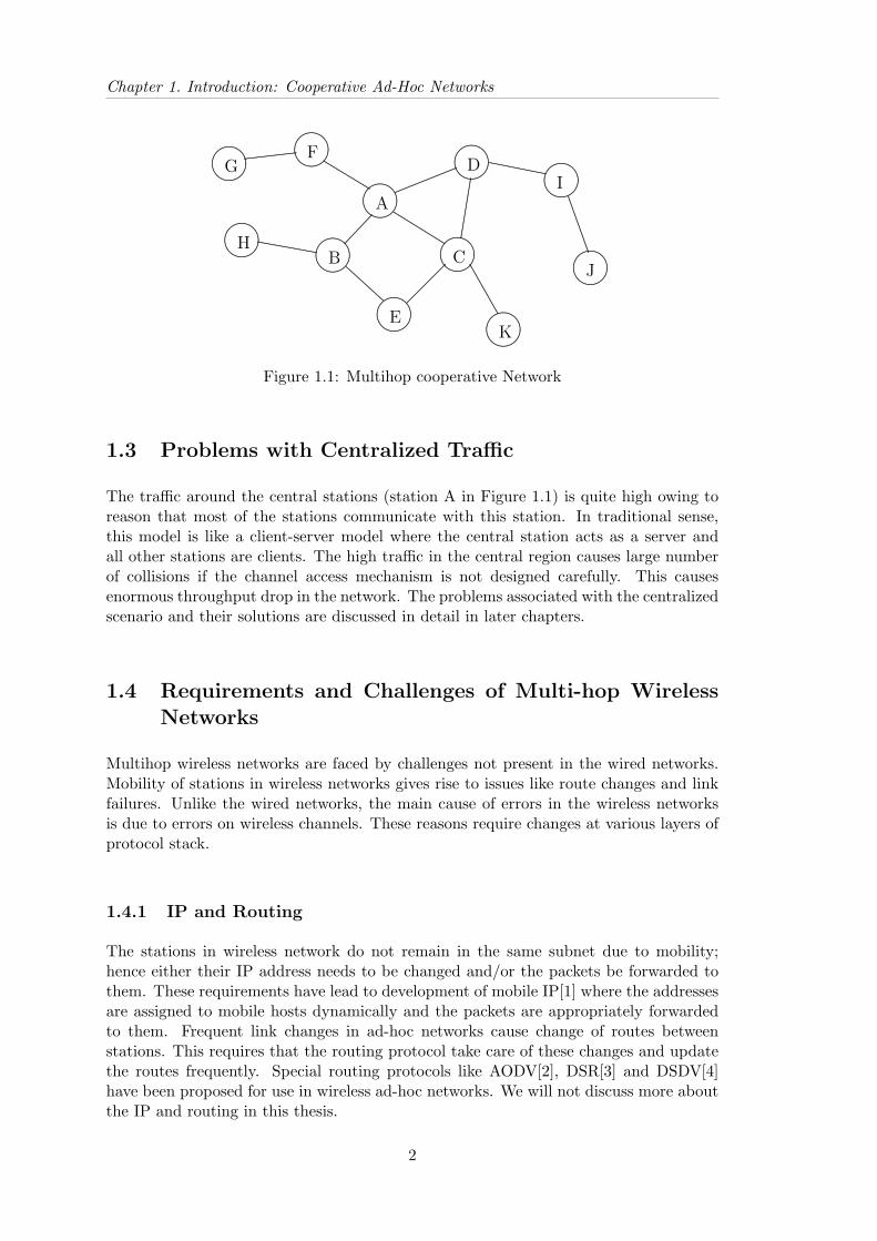
Cooperative multihop ad-hoc wireless networks consist of a group of stations connectedto each other over one or more hops. If two communicating stations are more than onehop away, the intermediate stations route the packets from source to destination. Dis-aster management operations and battalion of soldiers are the example of applicationsof such cooperative ad-hoc wireless networks. Most often, the traffic in these networksis directed towards a central controlling station. The controlling central station is morecapable than other stations and in most cases, can also communicate with headquar-ter/head office. The Figure 1.1 shows a multihop cooperative network with the centralcontrolling station labeled A. The stations B, C, D and F are directly connected tostation A over a single hop; the stations E, G, H, I and K are connected to the stationA over two hops; and the station J is connected to station A over three hops.
1
Chapter 1. Introduction: Cooperative Ad-Hoc Networks
........
....................
........................................................................................................................................................D
........
....................
........................................................................................................................................................A
........
....................
........................................................................................................................................................B ........
....................
.........................................................................................................................................................C
........
....................
........................................................................................................................................................E
........
....................
........................................................................................................................................................F
........
....................
.........................................................................................................................................................G
........
....................
........................................................................................................................................................H
........
....................
.........................................................................................................................................................I
........
....................
........................................................................................................................................................J
........
....................
........................................................................................................................................................K
............................................................................................ ..........................................
..........................................
.............................
...................................................................
.......................................................................................................
..................................................................................................
................................................................................................
......................................................................................
................
......................................................................................................
.............................................................................................
........................................................................................................
.........................................................................................
.....................................................................................
Figure 1.1: Multihop cooperative Network
1.3 Problems with Centralized Traffic
The traffic around the central stations (station A in Figure 1.1) is quite high owing toreason that most of the stations communicate with this station. In traditional sense,this model is like a client-server model where the central station acts as a server andall other stations are clients. The high traffic in the central region causes large numberof collisions if the channel access mechanism is not designed carefully. This causesenormous throughput drop in the network. The problems associated with the centralizedscenario and their solutions are discussed in detail in later chapters.
1.4 Requirements and Challenges of Multi-hop WirelessNetworks
Multihop wireless networks are faced by challenges not present in the wired networks.Mobility of stations in wireless networks gives rise to issues like route changes and linkfailures. Unlike the wired networks, the main cause of errors in the wireless networksis due to errors on wireless channels. These reasons require changes at various layers ofprotocol stack.
1.4.1 IP and Routing
The stations in wireless network do not remain in the same subnet due to mobility;hence either their IP address needs to be changed and/or the packets be forwarded tothem. These requirements have lead to development of mobile IP[1] where the addressesare assigned to mobile hosts dynamically and the packets are appropriately forwardedto them. Frequent link changes in ad-hoc networks cause change of routes betweenstations. This requires that the routing protocol take care of these changes and updatethe routes frequently. Special routing protocols like AODV[2], DSR[3] and DSDV[4]have been proposed for use in wireless ad-hoc networks. We will not discuss more aboutthe IP and routing in this thesis.
2

1.4 Requirements and Challenges of Multi-hop Wireless Networks
1.4.2 MAC
The link characteristics in wireless environments is very different from that of wirednetworks. At link layer we have to face following challenges:
Bandwidth: Bandwidth is the one of the most scarce resource in wireless networks.The available bandwidth in wireless networks (2-10Mbps) is far less than the wiredlinks (typically 100Mbps).
Range Issues: The transmission range of stations depends upon the transmitted powerand various sensitivity values. Unlike wired networks all stations on a LAN cannot listen to one another.
Power: The wireless stations are battery operated and therefore higher transmissionpower leads to faster degeneration of the batteries. On the other hand, if we keeptransmission power too small, the stations may no longer be in range of each other.
Collisions: Since all stations can not listen to each other, transmission from two stationmay lead to collision at another station.
Link Errors: Channel fading and interference cause link errors and these errors maysometimes be very severe.
1.4.3 Physical: Hidden and Exposed Node Problems
The transmission range of stations in wireless network is limited by the transmissionpower, therefore, all the station in a LAN can not listen to each other. This means thatnormal carrier sense mechanism which assumes that all stations can listen to each other,fails. In particular, this gives rise to hidden node and exposed node problem. Considerstations A, B, C and D as shown in Figure 1.2. With reference to the Figure 1.2, hiddenand exposed node problem can be described as follows:
........
...........................
.........................................................................................................................................................................................................................................................B
........
...........................
.........................................................................................................................................................................................................................................................C
........
...........................
.........................................................................................................................................................................................................................................................D
....................
....................
....................
......................................................................................................................................................................................................
.................................................................................................................................................................................................................
............................................................
....................
............................................................................................................................................ ..........
..............................................................................................................................................................................................
........
...........................
.........................................................................................................................................................................................................................................................
..........................................................................................................................................................................................................................................................................................................................................................................
................................................................................................................................................................................................................................................................................................................................................................................................
......................................
....................................................................................................................................................................................................................................................................................................................................................................................
Tx Range
Tx Range
Tx Range
Tx Range
A
Figure 1.2: Hidden and Exposed Node Scenario
Hidden node Problem: Stations A and C become hidden to each other as station Bcan listen both to A and C, but stations A and C can not listen to each other. If
3

Chapter 1. Introduction: Cooperative Ad-Hoc Networks
a packet is being transmitted from station A to station B and station C decides tostart a transmission (being hidden, it does not know of A-B transmission), therewill be collision at station B.
Exposed node Problem: If station B is sending data to station A, then station Cbecomes exposed to B and is forced to be silent even if it can send data to anotherstation. This is because station C finds carrier busy during transmission of stationB.
A simple and elegant solution to the hidden node problem is to use small packetscalled RTS (Request to Send) and CTS (Clear to Send) for handshaking before trans-mission of data packet. This solution was proposed by Karn [7] in his MACA protocolfor AX.25.
1.5 Thesis Objective and Scope
This work aims at improving the throughput in centralized cooperative wireless ad-hocnetworks by use of stations equipped with a new MAC called dual MAC at one-hopboundary of the central coordinating station. The main focus of this work is to presentthe design and architecture of dual MAC. The implementation of Dual MAC in publiclyavailable Network Simulator NS-2 is presented, and simulation results are discussed.The scope of this work is limited to centralized multihop networks to a large extent.The effect of node mobility is not considered.
1.6 Thesis Outline
The rest of the thesis is outlined in this section. In Second chapter, different medium ac-cess approaches, and the choices for MACs available for wireless networks are discussed.The operation of IEEE 802.11 MAC is discussed in detail. Third chapter discusses theoperation of IEEE 802.11 MAC in multihop networks, and describes the problems ofusing the DCF and PCF in such scenario. In chapter four, we discuss our approach toimprove the throughput of multihop ad-hoc networks, namely the design and architec-ture of dual MAC. The chapter five discussed the implementation of dual MAC in NS.The simulation set up and results are discussed in chapter six. Finally, thesis ends withthe conclusion and the scope for the future work in chapter seven.
4
Chapter 2
MAC in Multi-hop Ad-HocNetworks
2.1 Channel Access Mechanisms
The most important part of a MAC protocol is Channel Access Mechanism. The channelaccess mechanism is way of regulating the use of physical channel among the stationspresent in the network. It specifies when a station can send or receive data on thechannel. In this section, we discuss three channel access mechanisms, namely TDMA,CSMA/CA, and Polling.
2.1.1 TDMA
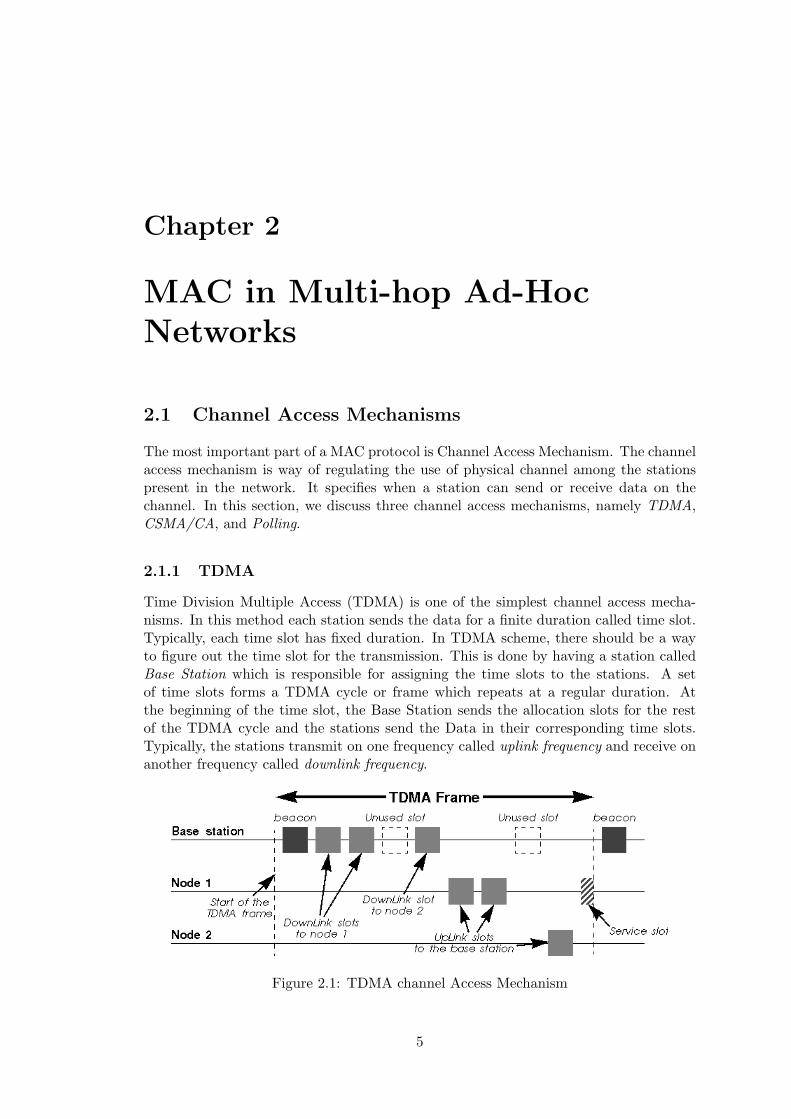
Time Division Multiple Access (TDMA) is one of the simplest channel access mecha-nisms. In this method each station sends the data for a finite duration called time slot.Typically, each time slot has fixed duration. In TDMA scheme, there should be a wayto figure out the time slot for the transmission. This is done by having a station calledBase Station which is responsible for assigning the time slots to the stations. A setof time slots forms a TDMA cycle or frame which repeats at a regular duration. Atthe beginning of the time slot, the Base Station sends the allocation slots for the restof the TDMA cycle and the stations send the Data in their corresponding time slots.Typically, the stations transmit on one frequency called uplink frequency and receive onanother frequency called downlink frequency.
Figure 2.1: TDMA channel Access Mechanism
5
Chapter 2. MAC in Multi-hop Ad-Hoc Networks
TDMA suits very well for telephone application because of very predictable trafficrequirement and is used in cellular telephone networks. However, it does not suite thepacket based applications where the data traffic is bursty and unpredictable. This isbecause TDMA is very strict and inflexible.
2.1.2 CSMA/CA
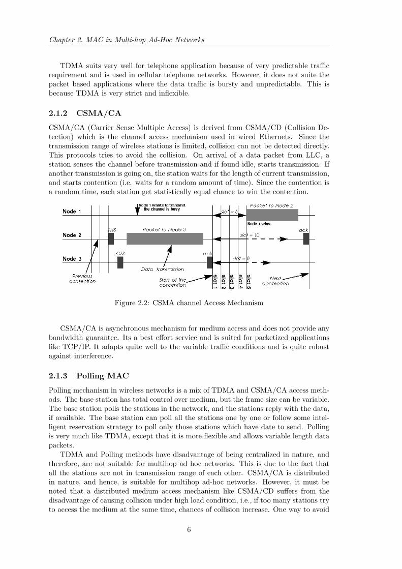
CSMA/CA (Carrier Sense Multiple Access) is derived from CSMA/CD (Collision De-tection) which is the channel access mechanism used in wired Ethernets. Since thetransmission range of wireless stations is limited, collision can not be detected directly.This protocols tries to avoid the collision. On arrival of a data packet from LLC, astation senses the channel before transmission and if found idle, starts transmission. Ifanother transmission is going on, the station waits for the length of current transmission,and starts contention (i.e. waits for a random amount of time). Since the contention isa random time, each station get statistically equal chance to win the contention.
Figure 2.2: CSMA channel Access Mechanism
CSMA/CA is asynchronous mechanism for medium access and does not provide anybandwidth guarantee. Its a best effort service and is suited for packetized applicationslike TCP/IP. It adapts quite well to the variable traffic conditions and is quite robustagainst interference.
2.1.3 Polling MAC
Polling mechanism in wireless networks is a mix of TDMA and CSMA/CA access meth-ods. The base station has total control over medium, but the frame size can be variable.The base station polls the stations in the network, and the stations reply with the data,if available. The base station can poll all the stations one by one or follow some intel-ligent reservation strategy to poll only those stations which have date to send. Pollingis very much like TDMA, except that it is more flexible and allows variable length datapackets.
TDMA and Polling methods have disadvantage of being centralized in nature, andtherefore, are not suitable for multihop ad hoc networks. This is due to the fact thatall the stations are not in transmission range of each other. CSMA/CA is distributedin nature, and hence, is suitable for multihop ad-hoc networks. However, it must benoted that a distributed medium access mechanism like CSMA/CD suffers from thedisadvantage of causing collision under high load condition, i.e., if too many stations tryto access the medium at the same time, chances of collision increase. One way to avoid
6

2.2 Available MACs
Figure 2.3: Polling Mechanism
this disadvantage is to intermix the Polling and CSMA/CA mechanism, as provided in802.11 PCF mode of medium access.
The most suitable access mechanism for ad hoc networks is the CSMA/CA as itis distributed and simple in nature. Another reason for using CSMA/CA in wirelessMACs is that wireless LAN cards with CSMA/CA are readily available.
2.2 Available MACs
2.2.1 IEEE 802.11 MAC
The IEEE 802.11 MAC was designed by a committee of IEEE. The goal of the committeewas to create a MAC standard for wireless LANs. In the 802.11 committee, each vendorhas pushed its own technology and specifications. The result is that the standard isvery versatile and well designed including all the optimizations and clever techniquesdeveloped by different vendors. The standard specifies one MAC protocol and threephysical standards: Frequency Hopping 1Mb/s (Only), Direct Sequence 1 and 2 Mb/sand diffuse infrared. Subsequently, the standard has been extended to support 2 Mb/sfor Frequency Hopping and 5.5 and 11 Mb/s for Direct Sequence (802.11b). The MAChas two main modes of operation, a distributed mode (CSMA/CA), and a coordinatedmode. 802.11 also uses MAC level retransmissions, RTS/CTS and fragmentation. Thestandard also has optional power management features and optional authentication andencryption (using the WEP, Wired Equivalent Privacy). Now the standard has alsobeen extended to be used in 5GHz band (IEEE 802.11a) and some extensions have beenadded in 2.4GHz band (IEEE 802.11b) to increase the bandwidth.
2.2.2 HiperLan-I
The HiperLan standard has been developed by researchers at ETSI (European Telecom-munications Standards Institute). It is developed without any strong vendor influenceand is quite different from existing products. The standard is quite simple, and usessome advanced features. It works in dedicated bandwidth (5.1GHz to 5.3GHz) and sodoes not have to use spread spectrum. The signalling rate is 23.5Mb/s, and 5 fixedchannels are defined. The protocol uses a variant of CSMA/CA based on packet timeto live and priority, and MAC level retransmissions. The protocol includes optionalencryption (no algorithm mandated) and power saving.
The nicest feature of HiperLan (apart from the high speed) is the ad-hoc routing: ifyour destination is out of reach, intermediate nodes will automatically forward it throughthe optimal route within the HiperLan network (the routes are regularly automatically
7

Chapter 2. MAC in Multi-hop Ad-Hoc Networks
recalculated). HiperLan is also totally ad-hoc, requiring no configuration and no centralcontroller.
The main deficiency of HiperLan standard is that it doesn’t t provide real isochronousservices (but comes quite close with time to live and priority), doesn’t t fully specify theaccess point mechanisms and hasn’t really been proved to work on a large scale in thereal world. Overhead tends also to be quite large (really big packet headers).
2.2.3 HiperLan-II
HiperLan II was the first standard to be based on OFDM modulation. Each sub-carriermay be modulated by different modulations (and use different convolutional code, asort of Forward Error Correction, FEC), which allow to offer multiple bit-rates (6, 9, 12,18, 27 and 36 Mb/s, with optional 54 Mb/s), with likely performance around 25 Mb/sbit-rate. The channel width is 20 MHz in 5MHz band, and includes 48 OFDM carriersused to carry data and 4 additional are used as references (pilot carriers - total is 52carriers, 312.5 kHz spacing).
HiperLan II is a Wireless ATM system, and the MAC protocol is a TDMA schemecentrally coordinated with reservation slots. Each slot has a 54 B payload, and the MACprovide SAR (segmentation and reassembly - fragment large packets into 54 B cells)and ARQ (Automatic Request - MAC retransmissions). The scheduler (in the centralcoordinator) is flexible and adaptive, with a call admission control, and the content ofthe TDMA frame change on a frame basis to accommodate traffic needs. HiperLan IIalso defines power saving and security features. HiperLan II is designed to carry ATMcells, but also IP packets, Firewire packets (IEEE 1394) and digital voice (from cellularphones). The main advantage of HiperLan II is that it can offer better quality of service(low latency) and differentiated quality of service (guarantee of bandwidth).
The IEEE 802.11 standard is the most widespread standard and has been deployedin wireless LANs. It is also being used in ad-hoc network testbeds, and lot of research isgoing on adapting 802.11 for ad-hoc networks. Besides that, it offers both infrastructuremode and infrastructure-less mode of operation and both can coexist together withoutany modifications. These factors make 802.11 MAC very suitable for ad-hoc networksand this thesis discusses the ad-hoc networks using 802.11 MAC.
2.3 IEEE 802.11 Operation
The IEEE 802.11 MAC offers two kinds of medium access methods, namely DistributedCoordination Function (DCF), and Point Coordination Function (PCF). DCF is thebasic access method in 802.11 and requires no infrastructure. When wireless stationsare within transmit range of each other, they form a Basic Service Set (BSS), and cancommunicate to each other using DCF. If the BSS contains only two stations, it is calledIndependent Basic Service Set (IBSS). Many BSSs may be connected by a DistributionSystem (DS) to form an Extended Service Set (ESS). An access point (AP) is thestation that provides access to DS services. The PCF is built on the top of the DCF,and is also referred to as infrastructure mode. It requires a polling station called PointCoordinator (PC), which acts as controlling station during poll. The PCF consists ofalternating Contention Free Periods (CFP) and Contention Periods (CP). During CFP,the PC polls other stations in the medium, and during CP, the access method becomesDCF.
8
2.3 IEEE 802.11 Operation
Figure 2.4: IEEE 802.11 Architecture
2.3.1 DCF Operation
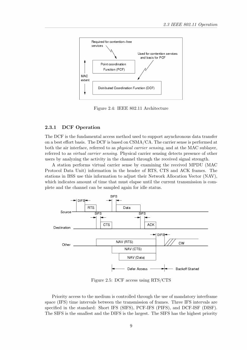
The DCF is the fundamental access method used to support asynchronous data transferon a best effort basis. The DCF is based on CSMA/CA. The carrier sense is performed atboth the air interface, referred to as physical carrier sensing, and at the MAC sublayer,referred to as virtual carrier sensing. Physical carrier sensing detects presence of otherusers by analyzing the activity in the channel through the received signal strength.
A station performs virtual carrier sense by examining the received MPDU (MACProtocol Data Unit) information in the header of RTS, CTS and ACK frames. Thestations in BSS use this information to adjust their Network Allocation Vector (NAV),which indicates amount of time that must elapse until the current transmission is com-plete and the channel can be sampled again for idle status.
Figure 2.5: DCF access using RTS/CTS
Priority access to the medium is controlled through the use of mandatory interframespace (IFS) time intervals between the transmission of frames. Three IFS intervals arespecified in the standard: Short IFS (SIFS), PCF-IFS (PIFS), and DCF-ISF (DISF).The SIFS is the smallest and the DIFS is the largest. The SIFS has the highest priority
9

Chapter 2. MAC in Multi-hop Ad-Hoc Networks
to access communication medium. For basic access method (without RTS/CTS), thestation waits for DIFS period and samples the channel again. If the channel is still idlethe station transmits MPDU. If the receiving station receives the packet correctly, itsends an ACK after waiting for the SIFS time. If RTS/CTS is used then the stationsends a RTS packet before sending MPDU. On receiving RTS, the receiving stationsends a CTS frame after SIFS time. On receiving CTS, the sender waits for SIFS timeand transmits the MPDU. Again, the ACK follows after SIFS period. It is also possibleto send the multiple fragments of a MPDU, where ACK to each fragment is sent afterSIFS time, and next fragment is sent after SIFS time of ACK.
The collision avoidance portion of CSMA/CA is performed through a random backoffprocedure. If a station initially senses the channel busy; then the station waits untilthe channel becomes idle for DIFS period, and then computes a random backoff timewithin a range called backoff window. For IEEE 802.11, time is slotted in time periodsthat corresponds to a Slot Time. After each unsuccessful attempt, the backoff windowis increased exponentially until a maximum value. The idle period after the DIFS periodis called contention window (CW). The advantage of this channel access method is thatit promotes fairness among stations, but its weakness is that it can not provide delaybound service to the stations.
2.3.2 PCF Operation
The 802.11 MAC offers contention free service by means of PCF. PCF is optional capa-bility and provides contention-free (CF) frame transfers. The PCF relies on the pointcoordinator (PC) to poll other stations. The polled stations can send the data withoutcontending for the medium. In a wireless LAN, the function of a PC is performed byAP within each BSS.
Figure 2.6: PCF access
The PCF is required to coexist with the DCF and logically sits on the top of DCF(see Figure 2.4). The PCF consists of alternating contention free period (CFP), andcontention period (CP) as shown in figure 2.6. In the CFP, the PC polls each of thestations present in the BSS. The PC specifies the start of the CFP by sending a beaconthat contains the length of CFP duration, among other things. All the stations in theBSS set their NAV for the duration of the CFP. The PC terminates the CFP by sendinga CF-End frame, and may also terminate it before the advertised CFP duration. Thetime difference between two beacons is called beacon period (BP) or CFP repetitioninterval, and is a multiple of beacon frame. The beacon also helps in synchronization
10

2.3 IEEE 802.11 Operation
and timing. The limits on durations of each of the frames are described in the IEEE802.11 standard [5]. In the CP, the stations use DCF to access the medium.
Figure 2.7: PCF Transmissions
In CFP, the PC polls each station by sending either Poll, Data + Poll or Data +ACK (for previous frames) + Poll. The polled station sends the data or Data + ACK(if polled by Data+Poll frame) to PC in response to the PC’s poll. It is also possibleto have station to station transmission during the CFP. The PCF offers connectionoriented polled service and therefore it reduces contention to a large extent. It is idealfor wireless LAN environments where all the stations are connected to the AP over asingle hop. However, at low traffic the overheads are quit high.
2.3.3 Summary
The DCF is suitable for the ad-hoc contention based service, whereas the PCF offerspolling based service. The DCF can exist independently in a network, but the PCFcoexists with the DCF. The DCF can be easily deployed in ad-hoc networks, as it doesnot require any infrastructure (like AP in case of PCF). The PCF can provide connectionoriented service but is suitable largely for the one-hop wireless LAN setup. However,simply using PCF in central part of the multihop network is not enough as the stationsin the PCF mode do not use RTS/CTS exchange during CFP. The lack of RTS/CTSexchange results in hidden and exposed node problems. We discuss this scenario ingreater detail in next chapter, and propose the solution to the problems encountered bysimple DCF/PCF operation of IEEE 802.11 MAC in multihop networks.
11

Chapter 3
IEEE 802.11 MAC in Multi-hopScenario
3.1 Multihop Scenario
The IEEE 802.11 MAC is designed for wireless LANs. The requirements of multihopad-hoc networks are more challenging than those of wireless LANs. In this chapter, weinvestigate the operation of IEEE 802.11 MAC in centralized multihop ad-hoc networks.The terms station and node are used interchangeably throughout the thesis. Multihopcooperative wireless ad-hoc networks will be simply referred to as multihop networks.
tt
t
t ............................................
............................................
............................................
........
..
........
..........................................
....................
.......................
.....................................................................................................................
.................................................................................................... .......... .......... .......... .......... .......... .......... .......... .......... ..........
....................
....................
......................................................
............................................
............................................
tt
............................................t
t tt
ttt
tt t
t tt
........................
............. ...........
..
............. ...........
..
............. ...........
..
............. ...........
..
............. ..........
..
............. ...........
..
............. ...........
..
............. ...........
..
............. ...........
..
............. ...........
.. ............. .............
............. ...........
..
Tx Range
Outer Stations
Inner Stations
Boundary Stations
Central Station
Figure 3.1: Multihop Scenario
Consider a multihop centralized scenario, as shown in the figure 3.1. For convenience,the stations inside the network are classified into following categories:
Central station is the central controlling station. Most of the traffic in the networkis directed towards it.
Inner stations are within one hop boundary of the central station.
Boundary stations are at one hop boundary of the central station. These stationsact as relaying stations for the stations outside the reach of central node.
Outer stations are outside the communication range of central node.
12

3.2 IEEE 802.11 Operation in Multihop Networks
3.2 IEEE 802.11 Operation in Multihop Networks
The 802.11 MAC with DCF mode of operation is the simplest choice in multihop ad-hoc networks. The reason for the choice of DCF is that it does not require any priorinfrastructure. Two or more stations can come together and form an BSS. This natureof DCF is very suitable for ad-hoc networks as the ad-hoc networks are simply formedby as set of stations coming together. In this section we discuss the operation of 802.11MAC in multihop networks, especially centralized multihop ad-hoc networks
In a centralized multihop network, as shown in Figure 3.1, the node density incentral region is higher than in the outer region. Most of the traffic is directed towardthe central node and boundary stations act as relaying stations. Therefore, the trafficnear the central station and its one hop neighbours is very high. Since the DCF is acontention based distributed protocol, it performs badly in high load conditions. Thepoor performance of DCF is due to fact that the collisions increase as more and morestations try to access the medium at the same time. It is well known that the pollingMAC performs better than pure CSMA/CA under high load conditions. Therefore,contention can be decreased by using polling MAC where central station acts as pollingstation.
........
....
........
........................................
............
............
............
........................
........................
....................................................................................................................................
........................
........................
............................................................................................................
........................ ............ ............ ............ ............ ............ ............ ............ ............ ............ ............ ............
........................
.....................................................................................................
u
u
u
u
u
u
u
uu
u...........................................................
...........................................................
...........................................................
...........................................................
...........................................................
...........................................................
...........................................................
...........................................................
........................................................... u
...........................................................
...........................................................
...........................................................
Stations using DCFStations using PCFCentral station
Figure 3.2: Hybrid PCF-DCF Operation
The most suitable choice for the polling MAC would be PCF mode of 802.11, as itis an extension of the DCF mode. Ebert et. all [8] have shown that the PCF modeperforms better than DCF when the number of stations in WLAN cell is very high.Therefore, we make the central node as Point Coordinator (PC), and it polls all theinner and boundary nodes during CFP period. This differs from conventional PCFoperation in WLANs where PC resides within AP. The outer stations still perform DCFsince the traffic in those regions is not high. The outer stations can send their datain contention period (CP) as all the stations perform DCF during CP. We refer thiscombination of PCF and DCF as hybrid operation as shown in figure 3.2.
The hybrid operation seems to be an ideal choice in multihop networks, but it givesrise to following problems:
• The stations that are polled by the Point Coordinator (PC) keep their NAV set
13
Chapter 3. IEEE 802.11 MAC in Multi-hop Scenario
during the CFP period, and therefore, can not receive from outer stations. It canalso be said that the boundary nodes become exposed to PC.
• Outer stations become hidden to PC, and vice versa, as there is no RTS/CTSexchange between PC and its one hop neighbours during CFP period.
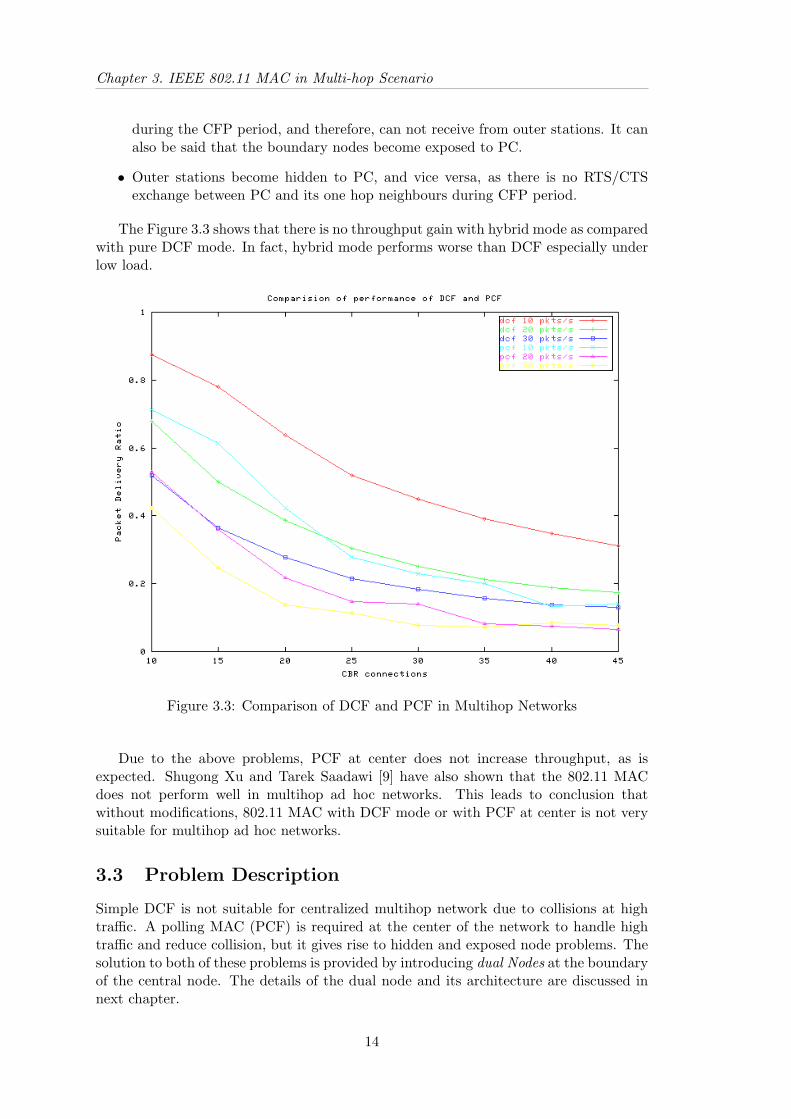
The Figure 3.3 shows that there is no throughput gain with hybrid mode as comparedwith pure DCF mode. In fact, hybrid mode performs worse than DCF especially underlow load.
Figure 3.3: Comparison of DCF and PCF in Multihop Networks
Due to the above problems, PCF at center does not increase throughput, as isexpected. Shugong Xu and Tarek Saadawi [9] have also shown that the 802.11 MACdoes not perform well in multihop ad hoc networks. This leads to conclusion thatwithout modifications, 802.11 MAC with DCF mode or with PCF at center is not verysuitable for multihop ad hoc networks.
3.3 Problem Description
Simple DCF is not suitable for centralized multihop network due to collisions at hightraffic. A polling MAC (PCF) is required at the center of the network to handle hightraffic and reduce collision, but it gives rise to hidden and exposed node problems. Thesolution to both of these problems is provided by introducing dual Nodes at the boundaryof the central node. The details of the dual node and its architecture are discussed innext chapter.
14

Chapter 4
Dual MAC
4.1 Need for Dual MAC
The centralized multihop ad hoc networks, as explained in earlier chapters, require aMAC that can provide distributed access mechanism. Furthermore, the MAC shouldbe able to handle high traffic in central region. The pure DCF operation, or hybridoperation (see Fig. 3.2) do not perform efficiently in multihop networks. The reasonsfor this inefficiency, as explained in section 3.2, are:
1. The DCF does not work well in high load scenario.
2. In case of hybrid operation, the polling and NAV setting in PCF nodes causeexposed and hidden node problems, thereby decrease the throughput.
To improve the throughput, boundary nodes should be able to receive date fromouter nodes during the CFP period (NAV is set). For this the MAC should be able toreceive even if its NAV is set. Also, transmissions from outer stations should not collidewith that of PC at boundary stations. To address above problems, we propose to equipboundary stations with dual MAC.
4.2 Overview of Dual MAC
A dual node is a station which has two independent MACs each communicating ondifferent logical channels. The two MACs are encapsulated inside the dual MAC. Thelogical channels could be FDMA or CDMA. Consider the boundary stations in Figures3.1 and 3.2 that are equipped with dual MACs. One of the MACs uses the PCF andis termed as PCF MAC. The second MAC uses the DCF and is termed as DCF MAC.The PCF MAC communicates with the PC, and the DCF mac communicates with theouter nodes. The exposed and hidden node problems in central region (see section 3.2)are eliminated as follows:
• Boundary stations use the PCF and the DCF on different channels. Therefore,the transmission of outer node does not collide with that of PC, and vice versa.
• The DCF MAC in the dual node can receive from outer nodes even when theNAV of PCF MAC is set during CFP period, thereby eliminating exposed nodeproblem.
15

Chapter 4. Dual MAC
4.3 Architecture of Dual MAC
6
?
6
?
6
?
6
?
6
?
Link Layer
PCFMAC MAC
Dual MAC
DCF
Phy Phy
Wireless Channel
Figure 4.1: Architecture of Dual Mac
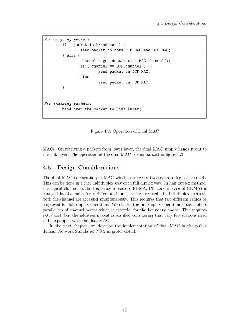
The dual MAC consist of two MACs in a single station each capable to send andreceive packets independently. Each MAC is designed to operate on different logicalchannels. As mentioned earlier, the channels can be either FDMA or CDMA but itdoes not make difference as far as the design of the dual MAC is concerned. As shownin Figure 4.1, the dual MAC is below the Link Layer and basically encapsulate twoactual 802.11 MACs. These two MACs which we refer to as PCF MAC and DCF MACrespectively, communicate on two different logical channels. The DCF MAC talks tothe stations that are operating in DCF mode and the PCF MAC talks to the PC andother stations which are in PCF mode. The dual MAC is a layer on the top of theseMACs and single point of interface to the Link Layer (LL). For all down-going packetsthe dual MAC layer acts as arbitrator and sends on either of the MAC below it. Forthe up-going packets, the job of dual MAC is simply to hand over the packet to the linklayer.
4.4 Operation
A packet arriving from link layer is received by the dual MAC and handed over to theMAC at appropriate frequency. The link layer finds out the MAC address of the next hopdestination by using ARP and hands out the packet to the dual MAC layer along withthe destination MAC address. In case dual MAC, the dual MAC also needs to know thechannel of the destination station. This could be done either by ARP table maintaininginformation about the channel on which the destination stations is communication, orby maintaining a local list of stations on each channel. The dual MAC figures out thechannel of the destination MAC and sends out the packet to the appropriate MAC. Thebroadcast packets like route discovery packets and ARP packets are sent to both the
16
4.5 Design Considerations
For outgoing packets:
if ( packet is broadcast ) {send packet to both PCF MAC and DCF MAC;
} else {channel = get_destination_MAC_channel();if ( channel == DCF_channel )
send packet on DCF MAC;else
send packet on PCF MAC;}
For incoming packets:
hand over the packet to Link Layer;
Figure 4.2: Operation of Dual MAC
MACs. On receiving a packets from lower layer, the dual MAC simply hands it out tothe link layer. The operation of the dual MAC is summarized in figure 4.2
4.5 Design Considerations
The dual MAC is essentially a MAC which can access two separate logical channels.This can be done in either half duplex way or in full duplex way. In half duplex method,the logical channel (radio frequency in case of FDMA, PN code in case of CDMA) ischanged by the radio for a different channel to be accessed. In full duplex method,both the channel are accessed simultaneously. This requires that two different radios beemployed for full duplex operation. We choose the full duplex operation since it offersparallelism of channel access which is essential for the boundary nodes. This requiresextra cost, but the addition in cost is justified considering that very few stations needto be equipped with the dual MAC.
In the next chapter, we describe the implementation of dual MAC in the publicdomain Network Simulatior NS-2 in greter detail.
17

Chapter 5
Dual MAC Implementation in NS
5.1 Existing Node Architecture in NS
-
-
?
?
?
6
6?
�
�
�?
mac
arptable
downtarget
Channel
downtarget
uptargetdowntarget
propagation
channel uptarget
uptarget
uptarget
Radio
Model
target
ARPLL
MAC
NetIFPropagation
IFQ
Figure 5.1: Architecture of NS Node
The Figure 5.1 shows the architecture of a NS mobilenode below the Link Layer.The outgoing packets after being processed by the routing layer, are handed over to thelink layer (LL object) through the target interface. The link layer is connected tothe ARP module (ARP object) through the interface arptable . After processing thepacket and resolving MAC address through ARP, the link layer hands over the packetto the Interface Queue (IFQ object) through the downtarget interface. The interface
18
5.2 Node Architecture of Dual MAC
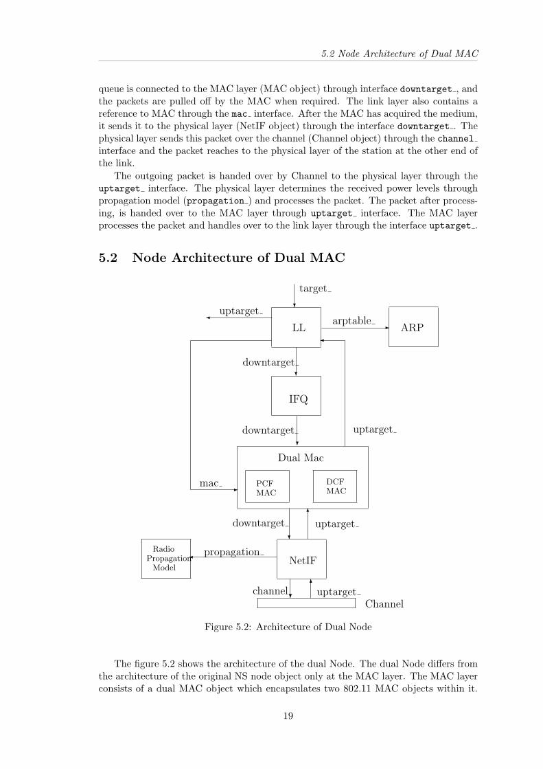
queue is connected to the MAC layer (MAC object) through interface downtarget , andthe packets are pulled off by the MAC when required. The link layer also contains areference to MAC through the mac interface. After the MAC has acquired the medium,it sends it to the physical layer (NetIF object) through the interface downtarget . Thephysical layer sends this packet over the channel (Channel object) through the channelinterface and the packet reaches to the physical layer of the station at the other end ofthe link.
The outgoing packet is handed over by Channel to the physical layer through theuptarget interface. The physical layer determines the received power levels throughpropagation model (propagation ) and processes the packet. The packet after process-ing, is handed over to the MAC layer through uptarget interface. The MAC layerprocesses the packet and handles over to the link layer through the interface uptarget .
5.2 Node Architecture of Dual MAC
-
?
�?
?
-
6?
�
�
6
?
arptable
downtarget
downtarget
uptarget
target
PCFMAC
DCFMAC
uptarget
mac
Dual Mac
Channel
propagation
channel uptarget
downtarget uptarget
PropagationRadio
Model
IFQ
ARPLL
NetIF
Figure 5.2: Architecture of Dual Node
The figure 5.2 shows the architecture of the dual Node. The dual Node differs fromthe architecture of the original NS node object only at the MAC layer. The MAC layerconsists of a dual MAC object which encapsulates two 802.11 MAC objects within it.
19

Chapter 5. Dual MAC Implementation in NS
All the upcoming and downgoing packets are first received by the dual MAC. In caseof downgoing packets, the dual MAC determines the channel on which this packet is tobe sent, and handles it over to appropriate MAC. In case of ingoing packets, it simplyhands over the packets to the MAC corresponding to received channel where it is handedto link layer after processing.
5.3 Implementation in NS
Dual_Mac :: recv(packet){
channel_id = channel id in packet header;if ( received packet is beacon ) {
pcf_channel_id = channel_id;PC = address of sender;
}
if ( direction == DOWN AND packet is broadcast) {send packet on DCF MAC;send packet on PCF MAC;return;
}
if ( direction == DOWN AND destination == PC ) {send packet on PCF MAC;return;
}
if ( direction == UP AND channel_id == pcf_channel_id ) {send packet on PCF MAC;return;
}
send packet on DCF MAC;return;
}
Figure 5.3: Dual MAC implementation in NS
The pseudo code for working of dual MAC in NS is shown in Figure 5.3. The dualMAC (class Mac Dual) is implemented by deriving the existing Mac class in NS. TheMac Dual object encapsulates two actual Mac 802 11 objects. The Mac 802 11 classand Packet class have also changed to incorporate dual MAC functionality. The Macclass has been change to incorporate the features necessary for the dual MAC. Thelogical channels are implemented by incorporating a variable channel id in the packet
20

5.3 Implementation in NS
header. The undesired packets (packets of different channel) are filtered by examiningthis variable in the received packet header. For the filtering, the changes have beendone to Mac 802 11 class. Each outgoing packet from MAC has its channel id variableset to appropriate channel. All interfaces like uptarget , downtarget , etc. have beenchanged such that all the packets that are received either from the Physical Layer orLink Layer are first received by the dual MAC.
As pointed out in section 4.4, the determination of channel for an outgoing packetcan be either done by changing ARP module or by using a local list of stations oneach channel. Currently the second approach is being used. The dual MAC stores thechannel-id of the PC in a variable as all the traffic for PCF MAC goes only to thePC. All the packets that are destined for PC are sent on PCF MAC. For incomingpackets, the channel-id is determined from the packet header and packet is handed overto appropriate MAC. The corresponding MAC updates its state and after processingthe packet and hands it over to link layer.
21
Chapter 6
Simulation and Results
6.1 Simulation Setup
This chapter describes the simulation of dual MAC. The simulation are done by usingthe public domain simulator NS-2. The following assumption are made in the simulation:
• The effect of propagation delay on the model are neglected. This is fairly re-alistic considering the fact the area in which stations are present is limited to1500mx1000m and inter-node distance is of the order of few hundred feet.
• The effect of channel errors is ignored in the simulations.
• No stations are operating in power save mode.
A finite buffer is maintained at each station. If the buffer fills, the newly generatedpackets are simply dropped. The safe distance upto which a stations can receive ismaximum 250m. The interference range is 500m. All the packets in the DCF mode aresent using RTS/CTS exchange. We use constant bit rate (CBR) traffic with data packetsize of 512 bytes. The routing protocol used is DSDV. The reason for choosing DSDVprotocol for routing is that it provides constant routing overhead in case of static andless mobile networks.
6.2 Simple Scenario and Results
In order to gain an understating of the dual MAC, we set up a simple scenario as shownin Figure 6.1. The number of stations in the topology is 18. The receiving stations forall the transmitting stations is the station labeled 0. The stations numbered 1, 2, 3, 4,5, and 6 are inner nodes. These stations are within one hop distance of the station 0.The stations 7, 8, and 9 are the boundary nodes. Rest of the stations in the networkare the outer stations.
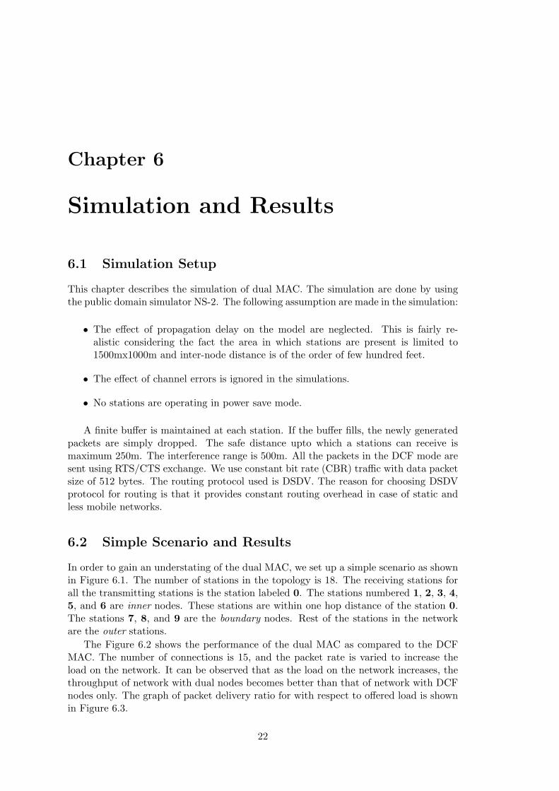
The Figure 6.2 shows the performance of the dual MAC as compared to the DCFMAC. The number of connections is 15, and the packet rate is varied to increase theload on the network. It can be observed that as the load on the network increases, thethroughput of network with dual nodes becomes better than that of network with DCFnodes only. The graph of packet delivery ratio for with respect to offered load is shownin Figure 6.3.
22

6.2 Simple Scenario and Results
..............................................................................................................................................................................................................................................................................................................................................................
....................
................................................................................................................................................................................................................................................
....................
....................
.................................................
.................................................
.................................................
.................................................
.................................................
.................................................
.................................................
.................................................
.................................................
.................................................
.................................................
.................................................
.................................................
.................................................
.................................................
.................................................
.................................................
.................................................
.................................................
.................................................
..........................................................................................................................................................................................................................................................................................................................................................................................................................
....................................................................
....................................................................
....................................................................
....................................................................
....................................................................
....................................................................
....................................................................
......... ....................................................
.....................................................................................................................................................................................................................................................................................................................................................................................................................................................................................
....................................................
..........................
3 10
11
0
1
2
4
5
6
7
8
9
1213
14
15
16
17
18
19
Tx Range = 250m
direction of date traffic
Figure 6.1: Simple Scenario
Figure 6.2: Throughput comparision of Dual MAC Vs DCF MAC in simple scenario
23
Chapter 6. Simulation and Results
Figure 6.3: Packet Delivery Ratio for Dual MAC Vs DCF MAC in simple scenario
24

6.3 Generic Scenario and Result
6.3 Generic Scenario and Result
In this section we describe the simulation results with random node placement. Thestations are placed in an area of size 1500m x 1500m. The center station is placedat the coordinate (750m, 750m). There are 8 boundary nodes placed symmetricallyaround the central station each at the distance of 200m from the central station. Thenumber of inner nodes in the topology is 12, and all other stations are more than onehop away from the central stations. The maximum number of hops is six. The stationsare randomly placed in the area.
Figure 6.4: Dual MAC Vs DCF MAC at 10 packets/sec
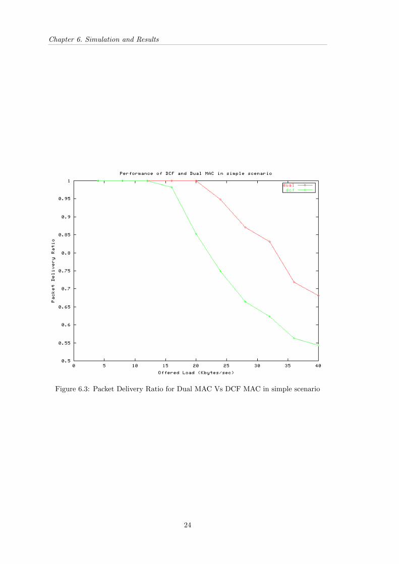
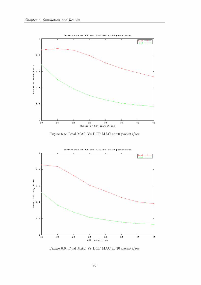
The graphs for the “packet delivery ratio Vs number of connections” for differentpacket rates are shown in the Figures 6.4, 6.5, and 6.6. The x-axis indicates the numberof CBR connections and the y-axis indicates the ratio of packets delivered to the desti-nations to the number of packets sent. The dual MAC offers substantially higher packetdelivery ratio for all the cases. It should be noted that the traffic at 30 packets/secondwith more than 10 connections corresponds roughly to a load greater than 30x10x512x8= 1228800 bites/sec (1.2Mbps). Even at this load the packet delivery ratio of dual MACis nearly 84% as compared to DCF at approximately 50%. The Figure 6.7 shows thethroughput of network with dual MAC and with PCF MAC. It can be clearly shownthat at high loads the performance of dual MAC is substantially better than the DCFMAC.
25
Chapter 6. Simulation and Results
Figure 6.5: Dual MAC Vs DCF MAC at 20 packets/sec
Figure 6.6: Dual MAC Vs DCF MAC at 30 packets/sec
26

6.4 Discussion on Results
Figure 6.7: Dual MAC Vs DCF MAC - overall Throughput
6.4 Discussion on Results
As seen from the graphs in the Figure 6.7, the performance of dual MAC is considerablybetter than that of DCF MAC. The increase in the performance is attributed to followingreasons:
• The PCF and DCF operate at different channels. This means that there is paral-lelism in the packet transmissions. This also eliminates the hidden node problemin the centralized scenario.
• The dual MAC offers parallelism by allowing the transmissions and receptions byDCF MAC even if the NAV of PCF MAC is set during the poll by PC. Thiseliminates the exposed node problem at boundary nodes which are exposed to thePC when the PC polls the stations.
We can see from the graphs that the throughput performance increase with dualMAC is more than twice that of DCF, which is remarkable considering that only fewstations have dual MAC.
27
Chapter 7
Conclusion and Future Work
7.1 Conclusion
The design of a MAC that meets the demand of a multihop wireless network is greatchallenge. The restrictions like limited bandwidth, low power, and limited transmissionrange make this challenge even greater. Further, the hidden and exposed node problemsoffer even more difficulties by increasing the chance of collision. In this work, we haveinvestigated the usefulness of IEEE 802.11 MAC protocol using the PCF and DCFmechanisms. We find that without modifications, the PCF and DCF are not very usefulin multihop networks. We also find that the high traffic in the central region of areal-life centralized multihop network makes the DCF unsuitable. We investigated theuse of PCF in central region to cope up the high traffic requirements in the centralregion. However, it gave rise to exposed and hidden node problems. The dual MACwas designed to eliminate exposed and hidden node problems in the central region of acentralized multihop network. The thesis discussed the design and architecture of dualMAC along with its implementation in NS.
The results show that the dual MAC performs reasonably better than the DCF accessmechanism. However, the dual MAC requires two physical radios and two separatechannels – one bound to PCF and another to DCF. We may however, note that thethroughput gain is worth the cost of dual MACs since only few nodes need to be equippedwith dual MAC.
The main focus of this thesis is to suggest a modification to the existing IEEE802.11 MAC so as to make it suitable in multihop ad-hoc networks, especially in thereal life centralized networks. The results presented in the thesis are applicable for staticscenario, nevertheless, the dual MAC is expected to perform better even under mobilescenario. The effect of mobility on performance of dual MAC still remains to be seen.
One of the reasons we could not study the effect of mobility was lack of implemen-tation of association and disassociation of stations to PC in PCF in NS. Lack of thisfeature restricted to allow stations to move and dynamically associate and disassociatefrom the PC.
7.2 Related Work
The dual MAC aims at eliminating the exposed and hidden node problems at the centerof the topology where PCF is used. Very little work has been done on centralizedtopologies, and using PCF in an ad-hoc networks. Most of the previous work has been
28

7.3 Future Work
concentrated on DCF mode of 802.11. Poojary, Krishnamurthy and Dao [10] have triedchanging power of control packets (RTS, CTS and ACK) with stations having powercontrol capabilities. They show that it does not increase the throughput of the networkdue to overheads. Deng and Haas propose dual Busy Tone Multiple Access (DBTMA)[11] for eliminating the exposed and hidden node problems. DBTMA used differentchannels for data and control packets. Nasipuri and Das [12], [13] have proposed MACwith multiple channels, and shown throughput improvement.
The dual MAC has been designed keeping in the mind the number of channelsavailable in 802.11. The most common method of physical access in available WLANcards is the DS-CDMA. The 802.11 with DS-CDMA allows three different channels. Thedual MAC can use any two of them. Another advantage of using dual MAC is that veryfew stations need the dual MAC capability (Boundary Nodes) and rest of the stationscan continue using existing WLAN cards. However, the dual MAC requires that PCFand DCF be done at different frequencies.
7.3 Future Work
One very useful extension to this work will be a scenario where one of the stationsautomatically becomes the PC after seeing high traffic in its vicinity. This requires amechanism for a node to become PC and inform other station about the same. Thiswill mean that the high traffic regions perform scheduled MAC, i.e., the PCF, and thesurrounding stations use the DCF. In this scenario, the dual nodes promise to be ofgreat use by providing parallelism at the boundary stations. The dual MAC can alsobe enhanced to use both the MACs in DCF and/or PCF mode, even if the station is ina region where only PCF or DCF is being used. (Currently only possible operation isthat of one of MACs using the DCF and another using the PCF at boundary stations.)This enhancement will mean that the parallelism offered by two channels will increasethe throughput considerably.
29

Bibliography
[1] C. Perkins, Network Working Group, RFC 3220: IP Mobility Support for IPv4,http://www.ietf.org/rfc/rfc3220.txt.
[2] Charles E. Perkins et. all, Mobile Ad Hoc Networking Working Group,Ad hoc On-Demand Distance Vector (AODV) Routing, http://www.ietf.org/internet-drafts/draft-ietf-manet-aodv-12.txt.
[3] David B. Johnson, David A. Maltz, Yih-Chun Hu, and Jorjeta G. Jetcheva,IETF MANET Working Group, The Dynamic Source Routing Protocol forMobile Ad Hoc Networks (DSR), http://www.ietf.org/internet-drafts/draft-ietf-manet-dsr-07.txt.
[4] Charles E. Perkins, Pravin Bhagwat, Highly dynamic Destination-SequencedDistance-Vector routing (DSDV) for mobile computers, ACM SIGCOMM ComputerCommunication Review, v.24 n.4, p.234-244, Oct. 1994.
[5] IEEE Std. 802.11, Wireless LAN Media Access Control (MAC) and Physical Layer(PHY) Specifications, 1999.
[6] Brian P. Crowe, I. Widjaja, J. Kim, P. Sakai, IEEE 802.11 Wireless Local AreaNetworks, IEEE Communications Magazine, September 1997.
[7] Phil Karn, MACA - A New Channel Access Method for Packet Radio, ARRL/CRRLAmature Radio 9th Computer Networking Group paper 801.22/92-39, March, 1992.
[8] Andreas Kopsel, Jean-Pierre Ebert, and Adam Wolisz, A Performance Comparisionof Point and Distributed Coordination Function of an IEEE 802.11 WLAN in thepresence of Real-Time Requirements, Proc. of 7th Intl. Workshop on Mobile Multi-media Communications (MoMuC2000), October 23-26, 2002.
[9] Shugong Xu, Tarek Saadawi Does IEEE 802.11 MAC Protocol Work Well in Multi-hop Wireless Ad Hoc Networks?, IEEE Communications Magazine, p.130-137, June2001.
[10] Neeraj Poojary, Srikanth V. Krishnamurthy, and Son Dao, Medium Access Controlin a Network of Ad Hoc Mobile Nodes with Heterogeneous Power Capabilities, IEEEInternational Conference on Communications (ICC 2001), volume 3, p.872-877, 2001.
[11] J. Deng, and Z. J. Haas, Dual Busy Tone Multiple Access (DBTMA): A NewMedium Access Control for Packet Radio Networks, IEEE ICUPC’98, Florence, Italy,October 5-9, 1998.
30
BIBLIOGRAPHY
[12] A. Nasipuri, and S. R. Das. A Multichannel CSMA protocol for multi-hop wire-less networks, Proc. of IEEE Wireless Communications and Networking Conference(WCNC’99), September 1999.
[13] Asis Nasipuri, and Samir R. Das, Multichannel CSMA with Signal Power-BasedChannel Selection for Multihop Wireless Networks, Proceedings of the IEEE FallVehicular Technology Conference (VTC 2000), September 2000.
[14] The VINT project, NS notes and documentation, editors: Kevin Fall and Kan-nan Varadhan, http://www.isi.edu/nsnam/ns.
[15] Ad Kamerman and Leo Monteban, WaveLAN-II: A High-Performance WirelessLAN for the Unlicensed band, 1997.
31