design and experimental demonstration of a large pedestal
TRANSCRIPT
Design and experimental demonstration of a large pedestal thulium-doped fibre
Nikita Simakov,1,* Alexander V. Hemming,1 Adrian Carter,2 Kevin Farley,2 Alan Davidson,1 Neil Carmody,1 Mark Hughes,1 Jae M. O. Daniel,1 Len Corena,1 Dmitrii
Stepanov,1 and John Haub,1 1Cyber and Electronic Warfare Division, Defence Science and Technology Organisation, Edinburgh, South Australia
5111, Australia 2Nufern Inc, 7 Airport Park Road, East Granby, CT 06026-9523, USA
Abstract: We present a novel large-mode-area thulium-doped fibre with a large pedestal design. We discuss the advantages of this large pedestal fibre in the context of overcoming limitations imposed by cleaving and splicing tolerances. Finally we demonstrate the use of such a fibre in constructing monolithic fibre lasers operating at 1.95 µm with 170 W of output power, 0.1 nm line-width and a diffraction limited beam quality of M2
X,Y = 1.02, 1.03.
©2015 Optical Society of America
OCIS codes: (140.3070) Infrared and far-infrared lasers; (140.3510) Lasers, fiber; (140.3460) Lasers.
References and links 1. W. A. Clarkson, N. P. Barnes, P. W. Turner, J. Nilsson, and D. C. Hanna, “High-power cladding-pumped Tm-
doped silica fiber laser with wavelength tuning from 1860 to 2090 nm,” Opt. Lett. 27(22), 1989–1991 (2002). 2. K. Scholle, S. Lamrini, P. Koopmann, and P. Fuhrberg, “2 µm laser sources and their possible applications,” in
Frontiers in Guided Wave Optics and Optoelectronics, B. Pal, ed. (InTech, 2010). 3. A. Hemming, S. Bennetts, N. Simakov, A. Davidson, J. Haub, and A. Carter, “High power operation of cladding
pumped holmium-doped silica fibre lasers,” Opt. Express 21(4), 4560–4566 (2013). 4. A. Hemming, N. Simakov, A. Davidson, S. Bennetts, M. Hughes, N. Carmody, P. Davies, L. Corena, D.
Stepanov, J. Haub, R. Swain, and A. Carter, “A monolithic cladding pumped holmium-doped fiber laser,” in CLEO: 2013, OSA Technical Digest (online) (Optical Society of America, 2013), paper CW1M.1.
5. G. D. Goodno, L. D. Book, and J. E. Rothenberg, “Low-phase-noise, single-frequency, single-mode 608 W thulium fiber amplifier,” Opt. Lett. 34(8), 1204–1206 (2009).
6. P. F. Moulton, G. A. Rines, E. V. Slobodtchikov, K. F. Wall, G. Frith, B. Samson, and A. L. G. Carter, “Tm-doped fiber lasers: fundamentals and power scaling,” IEEE J. Sel. Top. Quantum Electron. 15(1), 85–92 (2009).
7. M. Meleshkevich, N. Platonov, D. Gapontsev, A. Drozhzhin, V. Sergeev, and V. Gapontsev, “415 W single- mode CW thulium fiber laser in all-fiber format,” in European Conference on Lasers and Electro-Optics and the International Quantum Electronics Conference. CLEOE-IQEC 2007, CP2 (2007).
8. D. Creeden, B. R. Johnson, S. D. Setzler, and E. P. Chicklis, “Resonantly pumped Tm-doped fiber laser with >90% slope efficiency,” Opt. Lett. 39(3), 470–473 (2014).
9. G. Frith, D. G. Lancaster, and S. D. Jackson, “85 W Tm3+ -doped silica fiber laser,” Electron. Lett. 41(12), 687–688 (2005).
10. S. D. Jackson and S. Mossman, “Efficiency dependence on the Tm3+ and Al3+ concentrations for Tm3+-doped silica double-clad fiber lasers,” Appl. Opt. 42(15), 2702–2707 (2003).
11. S. D. Jackson, “Cross relaxation and energy transfer upconversion processes relevant to the functioning of 2 μm, Tm3+ -doped silica fiber lasers,” Opt. Commun. 230(1-3), 197–203 (2004).
12. S. D. Jackson and T. A. King, “High-power diode-cladding-pumped Tm-doped silica fiber laser,” Opt. Lett. 23(18), 1462–1464 (1998).
13. S. D. Jackson and T. A. King, “Theoretical modeling of Tm-doped silica fiber lasers,” J. Lightwave Technol. 17(5), 948–956 (1999).
14. K. Tankala, B. Samson, A. Carter, J. Farroni, D. Machewirth, N. Jacobson, A. Sanchez, A. Galvanauskas, W. Torruellas, and Y. Chen, “New developments in high power eye-safe LMA fibers,” Proc. SPIE 6102, 610206 (2006).
15. F. Wang, D. Shen, D. Fan, and Q. Lu, “Spectrum narrowing of high power Tm: fiber laser using a volume Bragg grating,” Opt. Express 18(9), 8937–8941 (2010).
16. Y. Tang, C. Huang, S. Wang, H. Li, and J. Xu, “High-power narrow-bandwidth thulium fiber laser with an all-fiber cavity,” Opt. Express 20(16), 17539–17544 (2012).
17. F. Wang, D. Shen, D. Fan, and Q. Lu, “Widely tunable dual-wavelength operation of a high-power Tm:fiber laser using volume Bragg gratings,” Opt. Lett. 35(14), 2388–2390 (2010).
#229443 - $15.00 USD Received 12 Dec 2014; revised 19 Jan 2015; accepted 29 Jan 2015; published 2 Feb 2015 (C) 2015 OSA 9 Feb 2015 | Vol. 23, No. 3 | DOI:10.1364/OE.23.003126 | OPTICS EXPRESS 3126

18. J. Liu, H. Shi, K. Liu, Y. Hou, and P. Wang, “210 W single-frequency, single-polarization, thulium-doped all-fiber MOPA,” Opt. Express 22(11), 13572–13578 (2014).
19. K. Yin, B. Zhang, G. Xue, L. Li, and J. Hou, “High-power all-fiber wavelength-tunable thulium doped fiber laser at 2 μm,” Opt. Express 22(17), 19947–19952 (2014).
20. L. Pearson, J. W. Kim, Z. Zhang, M. Ibsen, J. K. Sahu, and W. A. Clarkson, “High-power linearly-polarized single-frequency thulium-doped fiber master-oscillator power-amplifier,” Opt. Express 18(2), 1607–1612 (2010).
21. T. S. McComb, R. A. Sims, C. C. C. Willis, P. Kadwani, V. Sudesh, L. Shah, and M. Richardson, “High-power widely tunable thulium fiber lasers,” Appl. Opt. 49(32), 6236–6242 (2010).
22. J. Liu, K. Liu, F. Tan, and P. Wang, “High power thulium-doped all-fiber super-fluorescent sources,” IEEE J. Sel. Top. Quantum Electron. 20(5), 3100306 (2014).
23. H. Yoda, P. Polynkin, and M. Mansuripur, “Beam quality factor of higher order modes in a step-index fiber,” J. Lightwave Technol. 24(3), 1350–1354 (2006).
24. J. W. Nicholson, A. D. Yablon, S. Ramachandran, and S. Ghalmi, “Spatially and spectrally resolved imaging of modal content in large-mode-area fibers,” Opt. Express 16(10), 7233–7243 (2008).
25. A. D. Yablon, Optical Fiber Fusion Splicing (Springer-Verlag, 2005). 26. A. Hemming, N. Simakov, A. Davidson, D. Stepanov, L. Corena, M. Hughes, N. Carmody, P. Davies, J. Haub,
and A. Carter, “An efficient, high power, monolithic, single mode thulium fiber laser,” in Workshop on Specialty Optical Fibers and their Applications, (Optical Society of America, 2013.), paper T2.4. 25].
27. http://www.vytran.com/publications/datasheet_lfs4000_2010.pdf 28. D. Yu. Stepanov and L. Corena, “Bragg grating fabrication with wide range coarse and fine wavelength control,”
Opt. Express 22(22), 27309–27320 (2014). 29. B. Morasse, S. Chatigny, C. Desrosiers, É. Gagnon, M.-A. Lapointe, and J.-P. de Sando, “Simple design for
single-mode high power CW fiber laser using multimode high NA fiber,” Proc. SPIE 7195, 719505 (2009). 30. http://www.dilas.com/gdresources/downloads/products/DILAS_MMF-IS11_200um_793nm.pdf 31. M. A. Lapointe and M. Piché, “Line-width of high-power fiber lasers,” Proc. SPIE 7386, 73860S1–73860S8
(2009).
1. Introduction
Thulium-doped fibre (TDF) lasers provide an efficient method of generating high average power radiation in the 1.9 – 2.05 µm region [1]. Lasers operating in this wavelength range are able to address a variety of applications including LIDAR and remote sensing, medical applications, materials processing [2] and have recently been employed for the resonant pumping of holmium-doped fibre lasers [3, 4].
Several groups have demonstrated high average power levels with 608 W from a single stage amplifier [5] and more than 1 kW from a dual stage amplifier [6]. Both of these demonstrations operated at 2.04 µm and relied on diode pumping at 0.79 µm. Other strategies for the power scaling of thulium fibre sources include resonant pumping with either erbium based sources [7] or another shorter wavelength thulium fibre laser [8]. Of these approaches, the most electrically efficient approach to generating radiation at 2 µm is achieved by using 0.79 µm diode pumping of thulium and exploiting the cross-relaxation mechanism between thulium ions.
Cross-relaxation is a well-known effect in thulium-doped gain media and enables a quantum efficiency >1 with up to 2 laser photons generated for a single pump photon [9–13]. The thulium ion and aluminum oxide dopant concentrations must be large to achieve efficient cross-relaxation in a fibre. This requirement then places an additional restriction on fibre design in that the core must have a large numerical aperture (NA) with respect to the un-doped silica cladding. To minimize this effect on the NA, a higher index intermediary layer commonly termed a ‘pedestal’ has been shown to reduce the effective NA of the core [14].
However, there have been very few demonstrations of diffraction limited performance from large-mode-area (LMA) thulium-doped fibre designs incorporating a pedestal. Only one group has been able to report near diffraction limited (M2<1.1) performance at power levels exceeding 50 W [5]. Typically most thulium-doped fibre lasers operating at higher power levels are reported with beam qualities ranging from M2 = 1.2 – 2 [15–22]. The degradation in beam quality can lead to pointing instability, lower efficiency and spectral instability of the laser [23, 24]. These effects may make the laser less suitable for many applications. There is a clear need for a more robust thulium-doped fibre solution that will enable high power, diffraction limited performance from thulium-doped fibre sources.
We present two simple modifications to the design of conventional LMA TDFs to enable the production of splices with lower loss and reduce the sensitivity of these fibres to splice
#229443 - $15.00 USD Received 12 Dec 2014; revised 19 Jan 2015; accepted 29 Jan 2015; published 2 Feb 2015 (C) 2015 OSA 9 Feb 2015 | Vol. 23, No. 3 | DOI:10.1364/OE.23.003126 | OPTICS EXPRESS 3127
loss. The approach relies on using a smaller core diameter as well as incorporating a larger pedestal. We will discuss how these modifications ease the laser fabrication process. Finally, we use the fibre to construct high power, monolithic LMA fibre lasers with diffraction limited beam quality.
2. Fibre design and motivation
2.1 Current large-mode-area thulium doped fibres
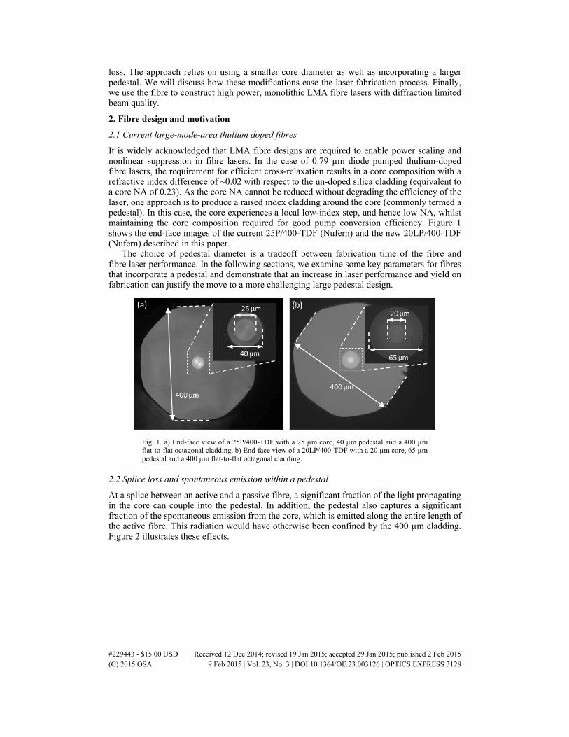
It is widely acknowledged that LMA fibre designs are required to enable power scaling and nonlinear suppression in fibre lasers. In the case of 0.79 µm diode pumped thulium-doped fibre lasers, the requirement for efficient cross-relaxation results in a core composition with a refractive index difference of ~0.02 with respect to the un-doped silica cladding (equivalent to a core NA of 0.23). As the core NA cannot be reduced without degrading the efficiency of the laser, one approach is to produce a raised index cladding around the core (commonly termed a pedestal). In this case, the core experiences a local low-index step, and hence low NA, whilst maintaining the core composition required for good pump conversion efficiency. Figure 1 shows the end-face images of the current 25P/400-TDF (Nufern) and the new 20LP/400-TDF (Nufern) described in this paper.
The choice of pedestal diameter is a tradeoff between fabrication time of the fibre and fibre laser performance. In the following sections, we examine some key parameters for fibres that incorporate a pedestal and demonstrate that an increase in laser performance and yield on fabrication can justify the move to a more challenging large pedestal design.
Fig. 1. a) End-face view of a 25P/400-TDF with a 25 µm core, 40 µm pedestal and a 400 µm flat-to-flat octagonal cladding. b) End-face view of a 20LP/400-TDF with a 20 µm core, 65 µm pedestal and a 400 µm flat-to-flat octagonal cladding.
2.2 Splice loss and spontaneous emission within a pedestal
At a splice between an active and a passive fibre, a significant fraction of the light propagating in the core can couple into the pedestal. In addition, the pedestal also captures a significant fraction of the spontaneous emission from the core, which is emitted along the entire length of the active fibre. This radiation would have otherwise been confined by the 400 µm cladding. Figure 2 illustrates these effects.
#229443 - $15.00 USD Received 12 Dec 2014; revised 19 Jan 2015; accepted 29 Jan 2015; published 2 Feb 2015 (C) 2015 OSA 9 Feb 2015 | Vol. 23, No. 3 | DOI:10.1364/OE.23.003126 | OPTICS EXPRESS 3128

Fig. 2. Illustration of a splice between a passive non-pedestal fibre and an active fibre containing a pedestal around the core. The pedestal is able to capture a significant fraction of the light coupled from the core at the splice (red arrows) and also the spontaneous emission from the excited rare-earth ions (blue arrows). At the output splice from active TDF to passive GDF only the radiation in the core of the active fibre is coupled into the core of the passive fibre.
Radiation coupled into the pedestal, due to either splice loss or spontaneous emission, experiences significant interaction with the core and potentially a very large gain. This leads to problems such as reduced hold-off in pulsed systems, and imposes a higher sensitivity to splice loss in both amplifier and laser systems where pedestals are used. There may also be significant backward propagating ASE guided by the pedestal.
Further, any radiation contained in the pedestal will not be guided by the core of the passive fibre and will couple to the cladding of the GDF at the splices at either end of the active fibre. This radiation will not only degrade the performance of the laser, but also has the potential to damage components such as fibre Bragg gratings (FBGs), fused combiners, isolators, laser diodes and cladding strippers.
The detrimental interaction between the radiation propagating in the pedestal and in the core can be estimated by considering the relative areas of both structures. For the 25P/400-TDF, the radiation propagating in the pedestal experiences only a slightly reduced (40% as shown in Fig. 3) interaction strength with the core. In the 20LP/400-TDF, the core diameter is reduced to 20 µm and the pedestal diameter is increased to 65 µm, substantially reducing this interaction strength from 40% to 10%.
Fig. 3. Effective overlap as a function of pedestal diameter for different core diameters
2.3 Mode-field diameter optimization for increasing yield
Low-loss splices are an essential process when assembling a high power laser with excellent beam quality. The impact of any splice loss is significantly increased when splicing to a fibre containing a pedestal as discussed in Section 2.2. Typically, the loss observed at a splice is
#229443 - $15.00 USD Received 12 Dec 2014; revised 19 Jan 2015; accepted 29 Jan 2015; published 2 Feb 2015 (C) 2015 OSA 9 Feb 2015 | Vol. 23, No. 3 | DOI:10.1364/OE.23.003126 | OPTICS EXPRESS 3129

attributed to three sources: mode-field diameter (MFD) mismatch, angular deviation between the fibres and transverse misalignment of the core.
The mode-field diameters of the fibres can be matched by high tolerance fabrication. It is a routine practice for manufacturers to be able to match the MFD of a passive and an active fibre sufficiently well such that this makes a negligible contribution to the splice loss.
The angular deviation of the fibre cores at a splice is typically associated with the net-deviation of the cleave angle from the normal. Splices with fibres having larger MFDs are more sensitive to these angular errors. The predicted splice loss as a function of angle for various MFD at a wavelength of 2 µm is shown in Fig. 4(a). Figure 4(b) shows the relationship between splice loss and transverse misalignment for various MFD [25].
Fig. 4. a) Impact of compound cleave angle mismatch on the loss at a splice for various mode-field diameters. b) Impact of transverse misalignment on the loss at a splice for various mode-field diameters.
Current commercially available LMA thulium-doped fibres have a core diameter of 25 µm with an effective MFD of 22.1 µm. The new large pedestal fibre under investigation here has a 20 µm core diameter, with a MFD of 18.2 µm. This 20% reduction in MFD results in a significant reduction (~30%) in loss at a splice for a given cleave angle. We have previously demonstrated robustly single-mode TDF lasers based on fibres with a 15 µm core diameter (MFD = 14.1 µm), however these devices used an outer cladding dimension of 250 µm which limits their ultimate power scaling potential [26].
The contribution of transverse misalignment to splice loss is related to the positioning accuracy of the splicer used to form the splice. Current splicers are able to achieve a typical transverse position resolution of ~20 nm [27]. This exceeds the required positioning accuracy for low-loss splicing and as a result, transverse misalignment is not a limiting factor on splice loss. Therefore, the most significant effort required is to reproducibly achieve cleave angles <0.3° degrees for a 400 µm diameter fibre. The accuracy of the achievable cleave angles effectively places an upper limit on the average power and performance that is achievable from a 2 µm fibre laser based on LMA TDF.
3. Laser performance
3.1 Laser design
Figure 5 shows a schematic of the laser. The output from a fibre-coupled laser diode was tapered and spliced to a passive fibre containing the highly reflective (HR) FBG. The 20/400-GDF passive fibre has a 20 µm diameter core with a matched MFD to the active TDF, a 400 µm diameter cladding and a 0.46 NA. The output of the fibre containing the HR FBG was spliced to a 6 m length of the 20LP/400-TDF described in Section 2. The active fibre was mounted in a water-cooled heat-sink which contains bends of 50 mm radius. The output end of the TDF was spliced to another length of 20/400-GDF passive fibre, which contains a 10% reflective output coupler (OC) FBG. The FBGs were fabricated in-house using a direct write method [28] and the Bragg wavelength was set at 1.95 µm. The passive fibre containing the OC includes a cladding stripper to remove any residual pump radiation and 2 µm light that may have been coupled into the cladding due to splice losses. A 1.5 mm long, 400 µm
#229443 - $15.00 USD Received 12 Dec 2014; revised 19 Jan 2015; accepted 29 Jan 2015; published 2 Feb 2015 (C) 2015 OSA 9 Feb 2015 | Vol. 23, No. 3 | DOI:10.1364/OE.23.003126 | OPTICS EXPRESS 3130

diameter core-less fused silica fibre was spliced onto the output. A 2° angle on the endcap was used to further reduce the amount of feedback from the Fresnel reflection at the glass-air interface.
Fig. 5. A schematic of the monolithic thulium-doped fibre laser and diagnostic equipment
The output from the laser was collimated using a high power IR lens (DPM Photonics) and then attenuated by CaF2 wedges. The beam was brought to a waist using an AR coated ZnSe lens and was then incident onto a pyroelectric detector array (Pyrocam III). The M2 was measured by translating the Pyrocam and recording the beam parameters through the beam waist. An optical spectrum analyser (Yokogawa OSA) measured the spectral output and calibrated thermal power meters (Ophir) monitored the output power levels.
3.2 Laser performance
Multiple lasers were constructed and produced at least 160 W of output power as shown in Fig. 6(a). The lasers operated at 50-52% slope efficiency depending on the splice quality. All were able to operate at the maximum pump power level of 340 W. The variation in slope efficiency is attributed to the variation of the active fibre length and to the splice losses in each laser. A typical beam profile measurement at maximum power is shown in Fig. 6(b). The beam evolved with an M2
X,Y = 1.02, 1.03 indicating that the laser is operating with a diffraction limited output. The intensity profile had a >94% quality of fit to Gaussian at all points. We confirm that all of the output radiation was confined to the core of the single-mode passive output fibre, with no measureable power in the cladding.
#229443 - $15.00 USD Received 12 Dec 2014; revised 19 Jan 2015; accepted 29 Jan 2015; published 2 Feb 2015 (C) 2015 OSA 9 Feb 2015 | Vol. 23, No. 3 | DOI:10.1364/OE.23.003126 | OPTICS EXPRESS 3131

Fig. 6. a) Output power at 1.95 µm vs launched pump power at 0.79 µm for several lasers. b) 4-sigma beam diameters taken through a focus of a 100 mm lens. A calibrated magnification lens was used to measure the waist diameters.
The evolution of the spectrum with respect to output power is shown in Fig. 7(a). The full-width half maximum (FWHM) bandwidth of the output was observed to increase from a resolution limited 0.05 nm to 0.1 nm as the laser power was increased from 16 W to 170 W. A low resolution (2 nm), high sensitivity scan of the entire thulium gain band is shown in Fig. 7(b). These measurements confirm that there is a negligible level of ASE present in the laser output, and no evidence of parasitic lasing at other wavelengths in the thulium gain band.
Fig. 7. a) Evolution of the spectrum with increasing output power measured with a resolution of 0.05 nm. b) Laser output spectrum measured with a resolution of 2 nm showing there is negligible ASE content at the output of the laser.
4. Discussion
4.1 Fibre design
Using larger pedestal in the active fibre reduces the sensitivity of the laser assembly to splice loss. This is a consequence of a significant reduction in the interaction strength between radiation propagating in the pedestal region with the active core. This approach can be applied to any TDF currently relying on the pedestal architecture. We expect that the large pedestal approach can also be applied with other dopants such as heavily doped Yb3+, Er3+ /Yb3+ and Er3+ fibres.
In addition to increasing the pedestal dimensions, we have also reduced the MFD by 20%. This reduces the splice loss due to angular deviation to a level that is compatible with the cleave angles readily achievable from current mechanical cleavers. This is a similar strategy to that previously implemented in ytterbium-doped fibre lasers [29].
These two strategies; reducing the splice loss by decreasing the MFD and reducing the sensitivity of the fibre to splice loss and ASE by increasing the pedestal diameter, create a significantly more robust thulium-doped fibre design.
#229443 - $15.00 USD Received 12 Dec 2014; revised 19 Jan 2015; accepted 29 Jan 2015; published 2 Feb 2015 (C) 2015 OSA 9 Feb 2015 | Vol. 23, No. 3 | DOI:10.1364/OE.23.003126 | OPTICS EXPRESS 3132
4.2 Laser operation
Using the large pedestal design discussed above, a series of 1.95 µm thulium-doped fibre lasers were constructed in-house as pump sources for holmium-doped fibre lasers [4]. The thulium lasers have a low component count, are completely monolithic and have a robustly single-mode output with efficiency ranging from 50 to 52% with respect to launched pump power. By correcting for pump losses in the components before the active fibre, and the Fresnel reflection from the uncoated end-cap, we estimate the internal efficiency of the thulium fibre to be ~58% with respect to absorbed pump power. This is further verified in a separate cut-back measurement. This slope is still far from the optimum efficiency of ~80% (assuming ideal cross-relaxation) and suggests that there are still significant efficiency gains to be made by optimizing the composition and fibre design.
The threshold for each laser was ~11.5 W, we associate this with the pumping rate required to reach transparency at the relatively short operating wavelength of 1.95 µm. We anticipate that longer operating wavelengths would have a lower threshold. The laser output power was limited by the pump power of the laser diode. Higher brightness pump diode packages are available that can launch >1 kW of power at 0.79 µm into a 400 µm, 0.46 NA cladding [30].
The spectrum of the laser was locked at 1.95 µm, with a width of <0.1 nm. We observed spectral broadening as the laser power increased from 15 W to 170 W. We attribute this broadening to four-wave mixing observed in CW ytterbium-doped fibre lasers [31]. The width of the broadening seems to be smaller in the thulium-doped fibre laser despite operating at similar cavity lengths, mode-field diameters and power levels. We attribute this to the reduced non-linear coefficient which scales inversely with wavelength.
The beam quality was measured to be M2X,Y = 1.02, 1.03 at the full output power from the
output of a cladding stripped, matched passive, single-mode fibre. No changes in pointing stability or degradation of the beam quality were observed while changing the pump power. We did not observe any additional spectral peaks that could potentially correspond to higher order mode reflections from the FBG. This suggests that the lasers are operating robustly on the fundamental mode.
5. Conclusion
We have discussed the limitations of small pedestal LMA thulium-doped fibres. A new approach utilising a smaller mode-field diameter and a larger pedestal design has been found to significantly reduce the complexity of fabricating single-mode TDF lasers. We anticipate that this approach will be transferred to other rare-earth doped fibre lasers that are currently relying on pedestals to achieve LMA operation.
Finally, we have validated this approach by using the large pedestal TDF to construct a number of robustly single-mode fibre lasers with an extremely simple design and a low component count. These lasers operated at up to 170 W output power levels, with excellent spectral quality and diffraction limited beam quality.
The fibre presented in this paper provides a robust active fibre laser platform. We anticipate that it will find utility in a wide range of thulium-doped fibre based applications where single-mode beam quality is critically required.
#229443 - $15.00 USD Received 12 Dec 2014; revised 19 Jan 2015; accepted 29 Jan 2015; published 2 Feb 2015 (C) 2015 OSA 9 Feb 2015 | Vol. 23, No. 3 | DOI:10.1364/OE.23.003126 | OPTICS EXPRESS 3133