design and fabrication of multi legged robot · klann linkage is developed by joe klann in 1994....
TRANSCRIPT

International Research Journal of Engineering and Technology (IRJET) e-ISSN: 2395-0056
Volume: 06 Issue: 03 | Mar 2019 www.irjet.net p-ISSN: 2395-0072
© 2019, IRJET | Impact Factor value: 7.211 | ISO 9001:2008 Certified Journal | Page 1018
Design and Fabrication of Multi Legged Robot
S.N. Teli1, Rohan Agarwal2, Devang Bagul3, Pushkar Badawane4, Riddhesh Bandre5
1Professor, Mechanical Engineering Department, BVCOE, Navi Mumbai
2,3,4,5Final Year Student, Mechanical Engineering Department, BVCOE, Navi Mumbai ---------------------------------------------------------------------***----------------------------------------------------------------------
Abstract – On the surface of the earth, there is the presence of wheeled and tracked vehicles. People, as well as animals, can go anywhere by the help of legs. Machine mainly consists of various mechanisms for their successful operation to get the desired output. Some of the famous mechanisms are the four-bar mechanism, single slider crank mechanism, double slider crank mechanism, etc., used for transmitting motion, force, torque etc. Our aim is to design and fabricate mechanical multi-legged robot and deformation in the kinematics links by using CADD software. The analytical data can be further used for reference purpose to design a walking robot to attain better design qualities. The analysis of the robot is based on the FEM concept integrated into Cad software called ANSYS R16.2. The aim of this project is to create an eight-legged robot to test new walking algorithm. We loosely based our design on spider because there has an advanced way in robotics on octopedal locomotion. Hopefully, the algorithm developed will be of use for the robotics community and in future society. Key Words: Klann, Jansen, Simulation, Coupled, Transient, Torque, Dynamic
1. INTRODUCTION
Klann linkage is developed by Joe Klann in 1994. This mechanism is a planar mechanism that converts the rotary motion of the crank to linear movement of the foot of the robot for one-half rotation of the crank & raises the foot for the second half and thus returning it to the starting point. Two of these linkages are at 180 degrees out of phase, will function as a wheel replacement. It was fabricated to simulate the gait of legged animal, example spider. Here the wheels are mostly replaced by either four legs or six legs sometimes eight legs is also possible to design a terrain robot. The linkage consists of following parts: - frame, a crank, two grounded rockers, and two couplers all connected by pivot joints. It consists of 6 links per leg. Another popular mechanism is Theo Jansen’s mechanism, designed by Theo Jansen to simulate a smooth walking motion. Theo Jansen has used his mechanism in different kinds of kinetic sculptures which are known as Strandbeests.There. There are many types of leg mechanisms such as Eight-bar leg mechanism, Strandbeests (applied Jansen linkage), Tokyo Institute of Technology walking chair, Ghassaei Linkage Tchebyshevs plant grade machine. But out of them, Klann mechanism and Jansen mechanism are most popular and are considered best in design.
The Fig.1 illustrates the main two mechanisms i.e. Jansen Mechanism and Klann Mechanism
Fig 1. Jansen & Klann Mechanism
The above image shows how the links connected to other links and how they can simulate. Klann mechanism is somewhat better in design because of their smaller number of links as compared to Jansen’s linkage. Therefore, we choose computer-aided design and analysis of walking robot based on Klann mechanism by using some CAD tools. These robots can basically go anywhere like living organisms on terrain areas and rocky areas as well as muddy surfaces.
There are many types of walking mechanisms but the 2 mostly method used are Theo Jansen`s Mechanism and Klann mechanism. So, we have decided to perform analysis by the help of Klann mechanism. Klann mechanism or linkage is basically an expansion of the four-bar mechanism. It was developed by Joe Klann in the Year 1994. wheels are basically ineffective on rough & rocky areas, thus robot with legs provided with Klann linkage are advantageous for walking vehicles.
The proportion of individual link in the mechanism is to optimize the linearity of the foot for one-half of the rotation of the crank. The remaining rotation of crank helps the foot to be raised to a predetermined height before returning to the starting position. Two of these linkages are coupled together at the crank and one-half cycle out of phase with each other will allow the frame of a vehicle to travel parallel to the ground. Our project is mainly useful for hazardous material handling, clearing minefields, or secures an area without putting anyone at risk. Wheels are mainly ineffective on rough and rocky areas, therefore robot with legs provided with Klann mechanism is beneficial for advanced walking vehicles. It steps over curbs, climbs stairs or travel areas that are currently not accessible with wheels. In this mechanism, links are mainly connected by the help of pivot joints and

International Research Journal of Engineering and Technology (IRJET) e-ISSN: 2395-0056
Volume: 06 Issue: 03 | Mar 2019 www.irjet.net p-ISSN: 2395-0072
© 2019, IRJET | Impact Factor value: 7.211 | ISO 9001:2008 Certified Journal | Page 1019
convert the rotating motion of the crank into the movement of foot similar to that of animal walking. The proportions of each link in the mechanism are designed to optimize the linearity of the foot for one-half of the rotation of the crank. The remaining rotation of crank allows the foot to be raised to a predetermined height before returning to the starting position and repeating the cycle. The military, law enforcement and private security firms can also be benefitted from applications of a mechanical spider. That below images shows some of the walking robots which are developed for rough terrain areas.
The Fig. 2 illustrates the Actual Four Leg mechanism known as Cheetah.
Fig 2. Cheetah Mechanism
The Fig. 3 illustrates the Four Leg mechanism known as Little Dog.
Fig 3. Little Dog Mechanism
Advantages of Walking Robots over Wheeled Robots:
1. Legged robots & vehicles can navigate to any kind of surfaces which is not possible for robots with wheels.
2. Wheel robots cannot jump or step and hence they have to take a different path, whereas legged robot can jump and step over obstacles.
3. Wheels require a continuous path to travel whereas legs can travel on any surface.
4. Legged robot helps us in exploring human and animal locomotion whereas it is impossible for wheel legged robots.
5. Once we start travelling from our regular habitat to the rough, rocky, sandy, steep and undesired terrain, we can understand that our brilliant invention of wheels turns out absolutely useless.
2. KLANN MECHANISM
It is basically a planar mechanism designed to simulate the gait of legged animal & function as a wheel replacement. The linkage consists of the following parts such as frame, a crank, two grounded rockers, and two couplers all connected by pivot joints. The proportions of links in this mechanism are defined to optimize the linearity of the foot for one-half of the rotation of the crank.
The left-over rotation of crank allows the foot to be raised to a predetermined height before returning to the starting position and repeating the cycle. Two of these linkages are coupled together at crank and one-half cycle out of phase with each other will allow the frame of a vehicle to travel parallel to the ground.
Joseph Klann has examined that all the combinations of dimensions calculated by this method may not work. There are many sets of dimensions that do not gives a smooth gait. So, we will make a small prototype to see its working of the following Length from Acrylic or Hard Cardboard to test our decided dimensions. Length of upper Rocker arm = 36.4 mm
Length of lower Rocker arm = 26 mm Length of Connecting arm = 102 mm Length of Leg = 151 mm Angle of Connecting arm = 170o Angle of Leg = 142o
The Fig. 4 represents a demo diagram of Single leg mechanism.
International Research Journal of Engineering and Technology (IRJET) e-ISSN: 2395-0056
Volume: 06 Issue: 03 | Mar 2019 www.irjet.net p-ISSN: 2395-0072
© 2019, IRJET | Impact Factor value: 7.211 | ISO 9001:2008 Certified Journal | Page 1020
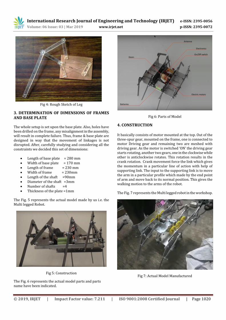
Fig 4: Rough Sketch of Leg
3. DETERMINATION OF DIMENSIONS OF FRAMES AND BASE PLATE The whole setup is set upon the base plate. Also, holes have been drilled on the frame, any misalignment in the assembly, will result in complete failure. Thus, frame & base plate are designed in way that the movement of linkages is not disrupted. After, carefully studying and considering all the constraints we decided this set of dimensions:
Length of base plate = 280 mm Width of base plate = 170 mm Length of frame = 230 mm Width of frame = 230mm Length of the shaft =90mm Diameter of the shaft =3mm Number of shafts =4 Thickness of the plate =1mm
The Fig. 5 represents the actual model made by us i.e. the Multi legged Robot.
Fig 5: Construction
The Fig. 6 represents the actual model parts and parts name have been indicated.
Fig 6: Parts of Model
4. CONSTRUCTION
It basically consists of motor mounted at the top. Out of the three-spur gear, mounted on the frame, one is connected to motor Driving gear and remaining two are meshed with driving gear. As the motor is switched ‘ON’ the driving gear starts rotating, another two gears, one in the clockwise while other is anticlockwise rotates. This rotation results in the crank rotation. Crank movement force the link which gives the momentum in a particular line of action with help of supporting link. The input to the supporting link is to move the arm in a particular profile which made by the end point of arm and move back to its normal position. This gives the walking motion to the arms of the robot. The Fig. 7 represents the Multi legged robot in the workshop.
Fig 7: Actual Model Manufactured

International Research Journal of Engineering and Technology (IRJET) e-ISSN: 2395-0056
Volume: 06 Issue: 03 | Mar 2019 www.irjet.net p-ISSN: 2395-0072
© 2019, IRJET | Impact Factor value: 7.211 | ISO 9001:2008 Certified Journal | Page 1021
5. DIMENSION AND PATH TRACKING ON LEGS
The project is mainly based on the default dimension for the Klann linkage from the Klann website to do analysis as well as CAD modelling for walking robot. But now we are going to check out the changes in the dimensions of the legs & thus observe the change in the path traced by the point where the main leg link touched with the ground. NOTE: no changes have been done in the dimensions of the links present.
The Fig. 8 represents the path traced by the point on the main leg of Klann mechanism, and how the legs are moving forward and backward.
Fig 8: No dimension changed
The Fig 9, shows how the path traced by the point on the main leg link. When it is touching the ground, the path is little twisted so that the flexibility and stability of the leg are changed and it is not suitable for the design of a walking robot.
Fig 9: Dimensions changed in the Connecting arm
The Fig. 10 shows the path traced by the point on the main leg link. It is somewhat similar to the Fig 8, but here the project cannot observe the motion of the main leg link. If we see the motion of the main leg link, there is a difference in the motion velocity.
Fig 10: Change in crank dimensions
6. INTRODUCTION TO ANSYS
Ansys Inc. is a famous engineering simulation software. This company is American public company based in Canonsburg, Pennsylvania. This software is mainly used for designing different products & semiconductors, as well as to create simulations that are used to test a product's durability, temperature distribution, fluid movements, and electromagnetic properties. Ansys was founded in 1970 by John Swanson. ANSYS software provides different platforms to analysis different types.
Before we proceed towards the analysis part, we are going to consider only one leg fixed to the frame, this will automatically reduce the difficulty of the analysis and thus reduce the number of the elements.
For the process of the analysis, we are going to consider a DC Motor which is fixed of 100 rpm with a torque of 16 kg-cm. the above input is only considered for dynamic analysis. By the help of 100 rpm speed, angular velocity can be calculated.
In this project we need to find the time taken for the crank to complete one rotation from given speed of the motor. The project is going to do the transient analysis basically the time-based action to find out the velocities of each link in Klann mechanism.
International Research Journal of Engineering and Technology (IRJET) e-ISSN: 2395-0056
Volume: 06 Issue: 03 | Mar 2019 www.irjet.net p-ISSN: 2395-0072
© 2019, IRJET | Impact Factor value: 7.211 | ISO 9001:2008 Certified Journal | Page 1022
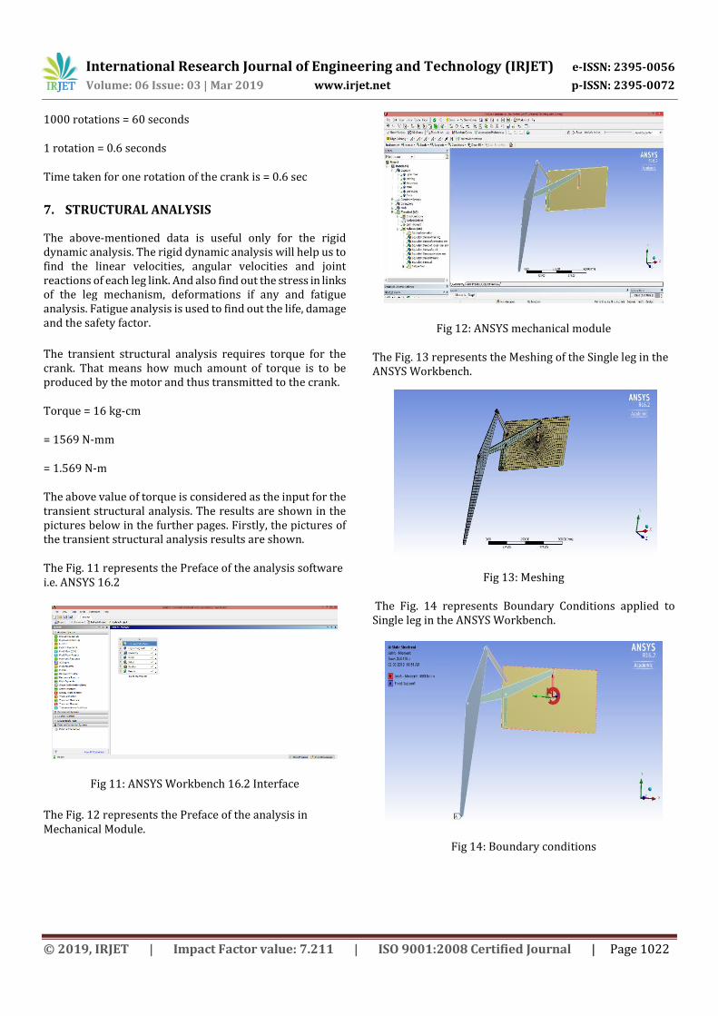
1000 rotations = 60 seconds
1 rotation = 0.6 seconds
Time taken for one rotation of the crank is = 0.6 sec
7. STRUCTURAL ANALYSIS
The above-mentioned data is useful only for the rigid dynamic analysis. The rigid dynamic analysis will help us to find the linear velocities, angular velocities and joint reactions of each leg link. And also find out the stress in links of the leg mechanism, deformations if any and fatigue analysis. Fatigue analysis is used to find out the life, damage and the safety factor.
The transient structural analysis requires torque for the crank. That means how much amount of torque is to be produced by the motor and thus transmitted to the crank.
Torque = 16 kg-cm
= 1569 N-mm
= 1.569 N-m
The above value of torque is considered as the input for the transient structural analysis. The results are shown in the pictures below in the further pages. Firstly, the pictures of the transient structural analysis results are shown.
The Fig. 11 represents the Preface of the analysis software i.e. ANSYS 16.2
Fig 11: ANSYS Workbench 16.2 Interface
The Fig. 12 represents the Preface of the analysis in Mechanical Module.
Fig 12: ANSYS mechanical module
The Fig. 13 represents the Meshing of the Single leg in the ANSYS Workbench.
Fig 13: Meshing
The Fig. 14 represents Boundary Conditions applied to Single leg in the ANSYS Workbench.
Fig 14: Boundary conditions
International Research Journal of Engineering and Technology (IRJET) e-ISSN: 2395-0056
Volume: 06 Issue: 03 | Mar 2019 www.irjet.net p-ISSN: 2395-0072
© 2019, IRJET | Impact Factor value: 7.211 | ISO 9001:2008 Certified Journal | Page 1023
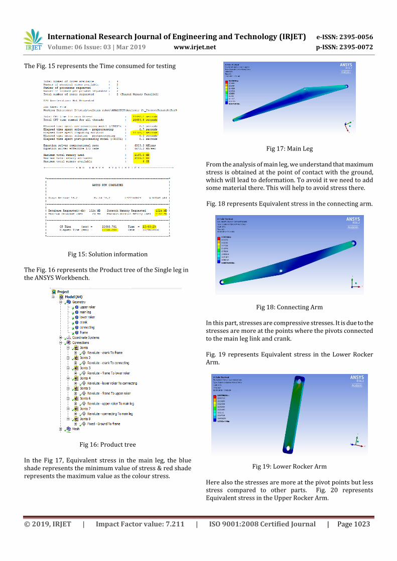
The Fig. 15 represents the Time consumed for testing
Fig 15: Solution information
The Fig. 16 represents the Product tree of the Single leg in the ANSYS Workbench.
Fig 16: Product tree
In the Fig 17, Equivalent stress in the main leg, the blue shade represents the minimum value of stress & red shade represents the maximum value as the colour stress.
Fig 17: Main Leg
From the analysis of main leg, we understand that maximum stress is obtained at the point of contact with the ground, which will lead to deformation. To avoid it we need to add some material there. This will help to avoid stress there.
Fig. 18 represents Equivalent stress in the connecting arm.
Fig 18: Connecting Arm
In this part, stresses are compressive stresses. It is due to the stresses are more at the points where the pivots connected to the main leg link and crank.
Fig. 19 represents Equivalent stress in the Lower Rocker Arm.
Fig 19: Lower Rocker Arm
Here also the stresses are more at the pivot points but less stress compared to other parts. Fig. 20 represents Equivalent stress in the Upper Rocker Arm.

International Research Journal of Engineering and Technology (IRJET) e-ISSN: 2395-0056
Volume: 06 Issue: 03 | Mar 2019 www.irjet.net p-ISSN: 2395-0072
© 2019, IRJET | Impact Factor value: 7.211 | ISO 9001:2008 Certified Journal | Page 1024
Fig 20: Upper Rocker Arm
Fig. 21 represents Equivalent stress in the Crank
Fig 21: Crank
The stresses in the crank because this link is mounted on the shaft of the motor. Thus, this link is responsible for the entire motion in the leg mechanism.
Fig 22 represents Equivalent stress in the Frame
Fig 22: Frame
The maximum stress is at the hole where the crank and the motor shaft are connected.
Fig 23 represents Equivalent stress in the Entire Mechanism
Fig 23: Entire Mechanism
8. OBSERVATIONS RECORDED FROM THE
TRANSIENT STRUCTURAL ANALYSIS
The above images show the equivalent stress distribution for all the parts of the robot. The maximum stress in complete model is 1.9 Mpa and the minimum stress is 0.066 Mpa.
Equivalent stresses in main leg link = 0.67Mpa
Equivalent stresses in connecting arm = 0.27Mpa
Equivalent stresses in crank = 1.95Mpa
Equivalent stresses in lower rocker arm = 0.069Mpa
Equivalent stresses in upper rocker arm = 0.40Mpa
Equivalent stresses in frame = 0.66Mpa
For analysis process, the project is going to fix a DC motor of 100 rpm with 16 kg torque.
Now we need to do the transient analysis of the model and for this we need to find time- based action of each link in klann mechanism. Thus, we need to find out time taken for crank to complete one rotation.
100 rotations = 60 seconds
1 rotation = 0.6 second
9. DYNAMIC ANALYSIS
International Research Journal of Engineering and Technology (IRJET) e-ISSN: 2395-0056
Volume: 06 Issue: 03 | Mar 2019 www.irjet.net p-ISSN: 2395-0072
© 2019, IRJET | Impact Factor value: 7.211 | ISO 9001:2008 Certified Journal | Page 1025
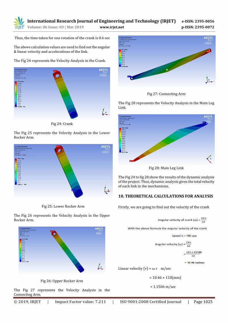
Thus, the time taken for one rotation of the crank is 0.6 sec
The above calculation values are used to find out the angular & linear velocity and accelerations of the link.
The Fig 24 represents the Velocity Analysis in the Crank.
Fig 24: Crank
The Fig 25 represents the Velocity Analysis in the Lower Rocker Arm.
Fig 25: Lower Rocker Arm
The Fig 26 represents the Velocity Analysis in the Upper Rocker Arm.
Fig 26: Upper Rocker Arm
The Fig 27 represents the Velocity Analysis in the Connecting Arm.
Fig 27: Connecting Arm
The Fig 28 represents the Velocity Analysis in the Main Leg Link.
Fig 28: Main Leg Link
The Fig 24 to fig 28 show the results of the dynamic analysis of the project. Thus, dynamic analysis gives the total velocity of each link in the mechanisms.
10. THEORETICAL CALCULATIONS FOR ANALYSIS
Firstly, we are going to find out the velocity of the crank
Linear velocity (v) = ω r m/sec
= 10.46 × 110(mm)
= 1.1506 m/sec
International Research Journal of Engineering and Technology (IRJET) e-ISSN: 2395-0056
Volume: 06 Issue: 03 | Mar 2019 www.irjet.net p-ISSN: 2395-0072
© 2019, IRJET | Impact Factor value: 7.211 | ISO 9001:2008 Certified Journal | Page 1026
Graphical or Relative velocity method:
Scale 1cm = 1.1506/3 m/sec = 0.38353 m/sec
(NOTE: For velocity diagram, graphical method is drawn in CAD software to get more accurate results & angles)
Construction of Velocity diagram with CAD tools:
The Fig 29 represents the Perpendiculars to the Respected Links.
Fig 29: Perpendiculars to the Respected Links
The Fig 30 represents the Velocity Diagram including the dimensions.
Fig 30: velocity diagram with dimensions
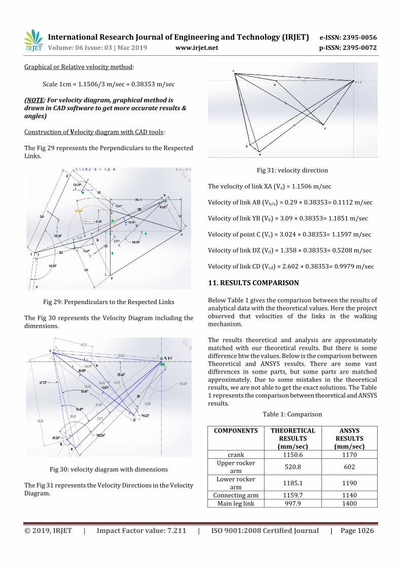
The Fig 31 represents the Velocity Directions in the Velocity Diagram.
Fig 31: velocity direction
The velocity of link XA (Va) = 1.1506 m/sec
Velocity of link AB (Vb/a) = 0.29 × 0.38353= 0.1112 m/sec
Velocity of link YB (Vb) = 3.09 × 0.38353= 1.1851 m/sec
Velocity of point C (Vc) = 3.024 × 0.38353= 1.1597 m/sec
Velocity of link DZ (Vd) = 1.358 × 0.38353= 0.5208 m/sec
Velocity of link CD (Vcd) = 2.602 × 0.38353= 0.9979 m/sec
11. RESULTS COMPARISON
Below Table 1 gives the comparison between the results of analytical data with the theoretical values. Here the project observed that velocities of the links in the walking mechanism.
The results theoretical and analysis are approximately matched with our theoretical results. But there is some difference btw the values. Below is the comparison between Theoretical and ANSYS results. There are some vast differences in some parts, but some parts are matched approximately. Due to some mistakes in the theoretical results, we are not able to get the exact solutions. The Table 1 represents the comparison between theoretical and ANSYS results.
Table 1: Comparison
COMPONENTS THEORETICAL RESULTS (mm/sec)
ANSYS RESULTS (mm/sec)
crank 1150.6 1170 Upper rocker
arm 520.8 602
Lower rocker arm
1185.1 1190
Connecting arm 1159.7 1140 Main leg link 997.9 1400

International Research Journal of Engineering and Technology (IRJET) e-ISSN: 2395-0056
Volume: 06 Issue: 03 | Mar 2019 www.irjet.net p-ISSN: 2395-0072
© 2019, IRJET | Impact Factor value: 7.211 | ISO 9001:2008 Certified Journal | Page 1027
The theoretical values are less than the ANSYS values, because in theoretical calculations, length are taken up to the centers of joints. But in the process of designing of cad model, we are considering the diameter of holes for the joint and this results in extra velocities in ANSYS results.
12. OBSERVATION- STRESSES AND DEFORMATIONS
The Table 2 represents the Equivalent stress distribution and Deformation of the components.
Table 2: Stress and Deformation
COMPONENTS EQUIVALENT STRESS (Mpa)
DEFORMATION (mm)
crank 1.952 0.00814 Upper rocker
arm 0.069 0.00675
Lower rocker arm
0.405 0.02017
Connecting arm 0.265 0.00761 Main leg link 0.673 0.02001
frame 0.663 0.00127
13. CONCLUSIONS
The final year project taught us many concepts of engineering. Some of the main concepts are Designing, kinematics, material science, CAD, manufacturing.
The project started with the literature review that was the most important step of designing the robot. Various research papers, websites and books were considered before designing it.
The manufacturing has started after research. After fabrication, the control mechanism was built. The control includes simple forward and backward motion.
After the successful fabrication and control of robot, the robot was tested for its movement. The robot was hence built and completed to the best of our efforts with future possibility of improvement.
14. REFERENCES
Ayers, Joseph; Witting, Jan; Olcott, Chris (2000a).
“Lobster Robots”. In: Proceedings of the
International Symposium on Biomechanisms, pp.
960 – 975.
Ayers, Joseph; Witting, Jan; Wilbur, Cricket;
Zavracky, Paul (2000b). “Biomimetic Robots for
Shallow Water Mine Countermeasures”. In:
Proceedings of the Autonomous Vehicles in Mine
Countermeasures, pp. 235 – 275.
Bares, John; Hebert, Martial; Kanade, Takeo (1989).
“Ambler: An Autonomous Rover for Planetary
Exploration”. IEEE Computer. Vol. 6; pp. 18 – 26
Binnard, Michael B.. (1995). “Design of a Small
Pneumatic Walking Robot”, M. Sc. Thesis. Massa-
chusetts Institute of Technology.
Bonvilain, Agnès (2003). “Microfabricated
Thermally Actuated Microrobot”. In: Proceedings of
the 2003 IEEE International Conference on
Robotics; pp. 2960 – 2965.
Colbrunn, Robb William. (2000). “Design and
Control of a Robotic Leg with Braided Pneumatic
Actuators”, M. Sc. Thesis. Case Western University –
Department of Mechanical and Aerospace
Engineering pp. 456-487.
Fiorini, Paolo. (2000). “Ground Mobility Systems for
Planetary Exploration”. In: Proceedings of the 2000
IEEE International Conference on Robotics; pp. 908
– 913.
Frank, A. (1968). “Automatic Control Systems for
Legged Locomotion”, USCEE Report No. 273;
University of Southern California; Los Angels,
California.
Hirose, Shigeo (1996). “Study on Roller-Walker
(Basic Characteristics and its Control)”. In:
Proceedings of the 1996 IEEE International
Conference on Robotics and Automation; pp. 3265 –
3270.
Kaneko, Makoto; Mizuno, Akihiko (2002). “Torque
Distribution for Achieving a Hugging Walk”. In:
Proceedings of the 2002 IEEE/RSJ International
Conference on Intelligent Robots and Systems; pp.
2613 – 2618.
Kikuchi, Fumitaka; Ota, Yusuke; Hirose (2003).
“Basic Performance Experiments for Jumping
Quadruped”. In: Proceedings of the 2003 IEEE/RSJ
Conference on Intelligent Robots and Systems; pp.
3378 – 3383.
BIOGRAPHIES
Prof. Dr. S.N. Teli Professor, Mechanical Engineering, BVCOE, Navi Mumbai
International Research Journal of Engineering and Technology (IRJET) e-ISSN: 2395-0056
Volume: 06 Issue: 03 | Mar 2019 www.irjet.net p-ISSN: 2395-0072
© 2019, IRJET | Impact Factor value: 7.211 | ISO 9001:2008 Certified Journal | Page 1028
Mr. Rohan Agarwal Final Year Student, Mechanical Engineering, BVCOE, Navi Mumbai
Mr. Devang Deepak Bagul Final Year Student, Mechanical Engineering, BVCOE, Navi Mumbai
Mr. Pushkar Badawane Final Year Student, Mechanical Engineering, BVCOE, Navi Mumbai
Mr. Riddhesh Rajesh Bandre Final Year Student, Mechanical Engineering, BVCOE, Navi Mumbai