design and implementation of a dual-camera wireless sensor...
TRANSCRIPT
Design and Implementation of a Dual-Camera Wireless Sensor Network forObject Retrieval
Dan Xie, Tingxin Yan, Deepak Ganesan, Allen HansonDepartment of Computer Science, University of Massachusetts Amherst
{dxie, yan, dganesan, hanson}@cs.umass.edu
Abstract
This paper presents the design and implementation of adual-camera sensor network that can be used as a mem-ory assistant tool for assisted living. Our system performsenergy-efficient object detection and recognition of com-monly misplaced objects. The novelty in our approach isthe ability to tradeoff between recognition accuracy andcomputational efficiency by employing a combination oflow complexity but less precise color histogram-based im-age recognition together with more complex image recog-nition using SIFT descriptors. In addition, our system canseamlessly integrate feedback from the user to improve therobustness of object recognition. Experimental results re-veal that our system is computation-efficient and adaptiveto slow changes of environmental conditions
1. Introduction
As the baby boomer generation ages, health care for theelderly poses a major challenge over the next decade. Wire-less sensor networks have often been referred to as the tech-nology that can provide an affordable solution to this prob-lem. Consequently, many research projects have exploredthe use of wireless sensors for medical care at home includ-ing a combination of wearable and ambient sensors for vitalsign, gait, and fall monitoring [6, 19]. In addition to mon-itoring for illnesses and potentially life-threatening situa-tions, an equally important challenge in home healthcare ofthe elderly is providing assistance in their day-to-day life.Moderate memory impairment is common as people age,hence a major problem for the elderly is locating frequentlyused ”common” objects such as keys, cellphones, PDAs,books and others.
There has been considerable recent interest in addressingthe problem of ”object finding” both in academia and indus-try. Many of these services seek to attach wireless tags onthe object, such as RFIDs [9, 17, 35], Bluetooth chips [15],or 802.15.4 radios [23, 25], making it easier to localize the
object. While this offers a feasible solution for objects suchas car keys and PDAs that already have wireless tags onthem, the solution is cumbersome since it requires that everypossible object that may be misplaced needs to be tagged apriori. Other approaches utilize visual information [24, 34],e.g., the ASSIST project proposed the use of PTZ (pan-tilt-zoom) cameras for object finding [34]. However, such PTZcameras are usually bulky and power hungry, making themhard to deploy around homes.
In this paper, we explore how low-power camera sen-sors can be distributed in a home environment to facilitateretrieval of misplaced objects. Small, battery powered cam-eras are portable, easy to deploy, and can be densely de-ployed for greater coverage. In addition, such as system canbe used across many untagged objects at home without re-quiring that each object be tagged individually. While therehave been many efforts in recent years to design low-powersmart camera networks for surveillance, object tracking,and object detection [14, 31, 16, 7], our work is fundamen-tally different in that we focus on achieving energy-efficientrecognition of commonly misplaced objects at home usingsuch a camera network.
The design of an object recognition system using low-power cameras poses significant technical challenges. Thefirst challenge is that state-of-art image matching tech-niques (e.g. SIFT [18]) require complex processing that iscomputationally intensive on embedded processors that aretypically used on sensor nodes, and consequently energy-intensive. This makes it essential to develop techniques thatare less complex and consume less energy but can still en-able robust image recognition. The second challenge is thatimage recognition typically requires a high-end sensor de-vice with a high-resolution camera, and substantial compu-tation and memory resources. However, the use of higher-end sensor platforms (e.g. iMote2 [3]) comes at the cost ofenergy-efficiency, and consequently lowers sensor lifetime.One commonly proposed approach is to use a multi-tier net-work [16], where a low-power and low-resolution wirelesscamera node (e.g. Cyclops [5]) is used for object detec-tion, and wakes up a higher power camera to perform ob-
2008 International Conference on Information Processing in Sensor Networks
978-0-7695-3157-1/08 $25.00 © 2008 IEEEDOI 10.1109/IPSN.2008.57
469

ject recognition only when needed. However, this does notentirely solve the problem since the high-power camera stillneeds to wakeup and take images periodically to update itsbackground model.
1.1. Contributions
This paper presents the design and implementation ofa low-power wireless camera network that can be usedas a memory assistant tool to find a small set of pre-selected common objects (cup, key, cellphone, etc) aroundthe house. The contributions of our system are summarizedbelow.
Energy-efficient Region-of-object Estimation: Ourfirst contribution is robust object detection and region-of-object (ROO) estimation using a dual-camera platform thatcombines a low-power Cyclops camera and a higher poweriMote2 camera. Our dual-camera platform is configuredsuch that the Cyclops and iMote2 camera lenses have verysimilar fields-of-view (FOV). A key contribution of ourwork is that we exploit the Cyclops camera not only forobject detection but also to determine where the objectis located relative to the iMote2 camera’s image by us-ing a SIFT (Scale-invariant Feature Transform) [18] basedimage-mapping algorithm. Such a technique eliminates theneed for background detection at the high-power camera,thereby saving energy.
Energy-efficient Object Recognition: Image process-ing techniques for object recognition typically use the SIFTalgorithm, which is computationally expensive and requiresat least a few seconds of processing per image (on lowpower processors of the type used here). A second con-tribution of our work is the use of two types of features -color and SIFT features - in order to reduce the energy re-quired for object recognition. The color and SIFT featuresare applied in a cascading manner which reduces energyconsumption without a significant drop in accuracy. Forevery new object, the color features are extracted quicklywith limited computation, and the object is classified usinga semi-supervised clustering algorithm. If the color featuresprovide an accurate match, no further action is taken. If not,SIFT features are extracted for the object and used for fur-ther classification. Our results show that this combination oftechniques almost three times more efficient than a schemethat only uses SIFT features, while being only 12% less ac-curate across a range of illuminations.
Incorporating User Feedback: A unique aspect of oursystem is the ability to incorporate user feedback to contin-ually improve the results of object classification. The sen-sor proxy provides a simple GUI to enable an elderly user toquery for objects that have been misplaced. The system thenreturns to the user the candidate object images that are mostlikely to match the query. The user is provided the option
of confirming the results and labeling the correct categoriesof the images, which provides valuable real-time feedbackto the system to refine the data model of semi-supervisedclustering. Such user feedback enables more robust objectrecognition in the presence of environmental dynamics.
The remainder of this paper is structured as follows. Sec-tion 2 presents an overview of our system. Section 3 and 4present the techniques of object detection and recognition.Section 5 presents the method for tag-based object retrieval.In Section 6 we give the implementation details of our sys-tem. The experimental results are presented in Section 7.Section 8 discusses related work. We discuss the futurework and present our conclusions in Section 9 and 10.
2. System overview
In this section we present an overview of the system.The software and hardware architectures of our system areshown in Figure 1.
2.1. System framework
Our system involves a network of dual-camera nodes,each of which comprises of a low-power and high-powertier that are physically connected together as shown in Fig-ure 2. The low-power camera sensor node (Tier-1) com-prises of a MICAz mote [1] equipped with a low fidelityCyclops camera sensor (CyclopsCam) [5, 28], and a 1GBNAND flash for storing images [21]. The high-power cam-era sensor node (Tier-2) comprises of a more-capable plat-form, the Intel Mote2 (iMote2) [3] equipped with a high fi-delity Enalab camera (EnalabCam) [2], and a 1GB SD cardfor image storage. The two cameras on the dual-cameranode are placed close enough so that they have similar field-of-view (FOV). User queries in our system can be posedfrom a PC or PDA that is connected to an 802.15.4 wirelessradio, and can communicate with the MICAz and iMote2nodes.
2.2. System operation
The operation of our system can be divided into threemain components: object detection, object recognition andimage retrieval. The Tier-1 low-power camera takes an im-age every few seconds, and performs still object detection,i.e., it determines if an object that is detected is likely to bea misplaced object as opposed to a moving object. If a stillobject is detected, the Tier-1 camera stores the location andsize of this object in its local flash memory store. Once abatch of still objects have been detected, the Tier-1 camerawakes up the Tier-2 node and transfers the stored images to-gether with information about the region in the image wherethe object was detected.
470

Figure 1. System architecture
Figure 2. The dual-camera node
The Tier-2 node uses an inter-camera region mappingfunction to map the Tier-1 ROOs to its own camera co-ordinates. This enables it to determine which regions in itsown view correspond to the new objects. Next, the Tier-2node takes an image using its high-resolution camera, ex-tracts the ROOs corresponding to new objects, and obtainsthe color histogram corresponding to each ROO. The ob-ject recognition procedure first tries to recognize the objectin each ROO by using the color histogram together with asemi-supervised k-means clustering. For objects that cannotbe classified correctly using color features, the SIFT recog-nition algorithm is used as additional evidence. The taggedclassification results from the Tier-2 node together with adetection timestamp are transmitted to a sensor proxy, andthe raw image data is locally stored on the flash memory inTier-2 node. The Tier-2 camera node then goes back to thesleep mode.
The user can query the system by specifying an objecttag that needs to be located. An approximate time frame ofinterest can also be provided by the user to further refine thesearch. The proxy locates the most recent event correspond-ing to the requested object, and queries Tier-2 sensors thathave reported the object. Since the Tier-2 sensor is asleep,this query is first received by the Tier-1 node which wakesup the Tier-2 sensor and forwards the query over the serial
connection. The matching image ROOs are retrieved, anddisplayed on a GUI to the user, who can mark images tobe ”Valid” or ”Invalid”. If the required object is not found,the proxy retrieves the previous event matching the query,and repeats the same procedure. This continues either un-til the object is located, or until no more objects were de-tected in the time frame of interest. Periodically, the proxyalso returns user feedback to the appropriate sensors, whichuse this information to refine their clusters, thereby enablingmore efficient and more robust recognition.
3. Object detection
The object detection procedure in our system involvestwo steps. The first step is detecting the presence of a stillobject at each Tier-1 CyclopsCam. This procedure aims tofilter out transient motion in the field of view of the camerasuch that only objects that stay relatively still are detected.The second step involves triggering the Tier-2 EnalabCam,and mapping from the ROO in the CyclopsCam to the Enal-abCam. This procedure aims to address the fact that theEnalabCam is woken up infrequently and cannot maintaina reliable background model locally. Hence the EnalabCamneeds to be told approximately where the detected object islocated in its image.
3.1. Object detection in low power tier
For object detection, the Cyclops node maintains thebackground using an average update model, which iscomputational-efficient. The background image Bm is up-dated by integrating the new frame Ic into the current back-ground with a first order recursive filter: Bm = (1 −α)Bm + Ic. By computing the differences between corre-sponding pixels in Ic and Bm, a motion mask Mmot is ob-tained to identify the foreground part in the current frame.A connected components analysis is performed on Mmot,and a set of image blobs exceeding a minimum size is ex-tracted. These blobs represent potential objects added to thescene.
To detect that a candidate blob represents a new objectplacement event as opposed to a transient motion event, weneed to check if this blob has been detected before and hasbeen still for a sufficiently long time. To achieve this, wecompare all the blobs in the current frame with those in theprevious frame. If the size and center of a blob is similarenough to those of a blob in the previous frame, these twoblobs are considered to be the same object. When the de-tection duration of an object blob becomes longer than apre-defined threshold, it is classified as a still object. Theobject blob is then extracted and saved on the local flashmemory of the MICAz mote.
471

3.2. Inter-tier triggering and ROO mapping
After the still objects are detected, the Tier-1 node needsto wake-up the Tier-2 camera from Deep-sleep mode. Sincethe wake-up of the iMote2 node from this state has long la-tency and consumes significant energy, the Tier-1 node trig-gers the Tier-2 node after a batch of still objects are de-tected. In this manner, the energy consumed to wakeupthe Tier-2 camera is amortized across multiple detections.Note that the wakeup delay is not a problem for our appli-cation since we are trying to detect still objects that remainin the scene for a significant duration. Our system will notbe as effective in a tracking scenario since the latency ofwakeup needs to be low in order to track motion. Althoughthe FOVs of two cameras are similar, there may be slighttranslation, rotation and considerable scaling between themdue to installation bias and the nature of the mechanicalmounts. To achieve robust region mapping from the pix-els Pj = [ux, uy, 1]T in CyclopsCam image to the pixelsP
′
j = [vx, vy, 1]T in EnalabCam image, a motion model isdefined based on the affine transformation.
P′
j = Dx0,y0Ssx,syRθPj
where Dx0,y0 is the translation matrix, Ssx,sy is the scalematrix and Rθ, the rotation matrix. In order to solve themotion model, the dual-camera node executes a calibrationprocedure at system deployment time. Both cameras takean image simultaneously, and the Tier-1 node transfers itsimage over the serial port to the Tier-2 node. The Tier-2node then extracts SIFT descriptors [18] from the two im-ages. Since the SIFT descriptors are invariant to the imagerotation, scale, and translation expected in this application,they provide a consistent set of local descriptors to matchbetween the two images. This calibration procedure is typi-cally more computationally intensive than object recogni-tion since it needs to be performed on the entire imageas opposed to just the ROO. However, this is a one-timecomputation, hence its overhead is a very small fraction ofoverall energy resources. After the inter-tier calibration isdone, any ROO in CyclopsCam image can be mapped tothe EnalabCam image efficiently using the motion model.Figure 3.b shows a mapping result, in which the boundingbox around a book that is detected on the desk in the upperCyclopsCam image is mapped to the appropriate rectanglein the lower EnalabCam image.
4. Semi-supervised object recognition
Given the Region-of-Object extracted by the object de-tection module, the next task of the Tier-2 node is to effi-ciently recognize the object. Our approach includes threeprocedures: feature extraction, object recognition and con-strained cluster update.
(a) (b)
Figure 3. An example of Field-of-View andROO mapping: (a) Control points found bySIFT. (b) The ROO mapping result.
4.1. Feature extraction
We use two kinds of features to classify objects. The firsttype of feature is a color histogram. Color histogram match-ing is one of the most widely used algorithms for detectingand recognizing objects in images [11]. Our system cal-culates a 32-bin hue histogram for each ROO image. Thesecond type of feature that we use is the SIFT descriptor,which represents an image as a collection of local featurevectors that are invariant to image translation, scaling, ro-tation, and partially invariant to illumination changes andaffine or 3D projection [18]. Given two images, a matchingalgorithm is performed to calculate the number of matchingpoints between them, which represent the similarity.
Both color and SIFT features have their advantages andlimitations in object recognition. Color features can be cal-culated in a computationally inexpensive manner, and areinvariant to severe scale, rotation and 3D projection; how-ever, they are not invariant to illumination changes. SIFTtolerates illumination changes and is widely considered tobe one of the best feature representation methods, but it iscomputationally intensive and does not perform well for de-formable objects or object that has no consistent texture inappearance.
Our system uses a combination of the two features in acascading manner. The idea is to use color features to fil-ter out irrelevant images and to classify images that havedistinctive color hues. The SIFT features are then used torecognize the remaining images that are hard to classify us-ing only color. This combination enables us to tradeoff be-tween efficiency and robustness, since the SIFT matching isperformed only on a small set of un-classified but relevantimages. We note that the idea of combining two kinds ofimage features for more robust detection has been consid-ered in image processing literature [29, 32, 27], however,we exploit this technique for energy-efficiency as opposedto detection accuracy.
472

4.2. Object recognition procedure.
The object recognition procedure starts by gathering asmall set of object images as training samples and mak-ing the initial clustering division with standard k-meansalgorithm. During this phase, clusters may be tagged by auser - for instance, one cluster might correspond to the cupwhereas another might correspond to the cellphone. Afterthis training phase, the system can be used to monitor thescene continually, and recognize the object detected usingthis initial cluster model. We now describe the recognitionapproach on an object oi. The pseudocode of the algorithmis shown in Algorithm 1.
4.2.1. Recognize by Color histogram. The recognitionprocedure first tries to classify a new object using color his-togram clustering since this can be done efficiently. Sincecolor histogram is a less precise feature, we use it in twoways: (a) to filter irrelevant images that are unlikely to be anobject of interest and hence can be immediately discarded,and (b) to determine if an object can be recognized solelyusing the color histogram, in which case the SIFT descrip-tor based matching need not be performed. The procedureis shown in the first four steps of Algorithm 1.
The algorithm first finds the distance between the colorhistogram of the new object oi and each cluster centroid,dij . In step 2, this distance is used to determine a normal-ized cluster membership metric, Rij , which represents thelikelihood that object oi belongs to cluster j. If the mini-mum distance of oi to all clusters is two times larger thanthe maximum of the distances between all samples to theircluster centroids, oi will be considered to be an irrelevantobject and will be discarded. Otherwise, in Step 4, thealgorithm checks to see if the best matching cluster (i.e.the cluster with maximum membership metric) exceeds apre-determined threshold, TR. If so, oi is considered touniquely belong to the cluster. In this case, the algorithmmatches the object to the tag associated with the cluster(e.g. cup, or cellphone), and terminates.
4.2.2. Combine the Color and SIFT features. Whilethe color feature-based classification filters irrelevant im-ages and identifies images that have clear membership inone cluster, there may be a number of images that are closeto multiple clusters and cannot be classified accurately. Weuse the SIFT features to identify such cases. Classifica-tion using SIFT features involves three steps. First, a previ-ously observed image that is closest to the centroid of each”nearby cluster” (the cluster j such that Rij is larger thana threshold TL
R ) is chosen as the ”representative” image forthe cluster. This is done because the clusters were built us-ing color features, not SIFT descriptors, hence we cannotdirectly use the clusters for SIFT-based classification. Sec-
ond, the SIFT descriptors for the new image are comparedto the representative images for each cluster, and a SIFTcluster membership score is assigned based on the similar-ity. Finally, a combined score is assigned to the new objectbased on a weighted combination of the color-based and theSIFT-based membership metric. The object is consideredto belong to all clusters, and assigned all tags for which theweighted score is greater than a pre-defined threshold.
Algorithm 1: Pseudocode of object recognition procedure.Input: object oi
Current model: Sample set X and k clusters {Xh}kh=1
Parameters: TR, T LR , α, THtag
Method:1. Calc histogram xi for oi.2. Calc membership of oi to all cluster centroids µj :
Rij = 1/(d2ij
∑kj=1(1/d2
ij)), where dij = ‖xi − µj‖.3. If min(dij) > 2max(dlj)
l=n,j=kl=1,j=1 , oi 3 {Xh}kh=1, exit.
4. If max(Rij) > TR, similarityij = Rij , goto step 6.5. (1) For each µr such that Rir > T L
R , do:Calc/save SIFT descriptors for oi and the closest sam-ple sr to µr; Calc number of SIFT matching points Mir
between oi and sr .(2) For the rest µr such that Rir < T L
R , let Mir = 0.(3) Calc Rir
SIFT = Mir/∑k
j=1 Mij for all µr .(4) l = maxr(R
irSIFT ). Let oi, sl → S.
(5) similarityij = Rij + αRijSIFT .
6. Let k = maxj(similarityij), oi ∈ Xk.7. For all j that similarityij > THtag ,
stringof(µi)→ Tags.
This procedure is shown in Steps 5-7 of Algorithm 1. Instep 5, we calculate the number of SIFT matching pointsbetween oi and the representative image sj correspond-ing to each cluster. For cluster j, sj is the closest sampleto the centroid µj . We can then calculate the number ofSIFT matching points Mij between oi and sj in each clus-ter. Rij
sift represents the SIFT similarity between oi and thesample sj in cluster j. Thus Rij
sift represents the evaluationscore of the membership of oi to cluster j given by SIFTfeatures.
The overall evaluation score of the identity of oi
is calculated by combining color and SIFT features:similarityij = Rij + αRij
sift, where α is a weight thatreflects the importance of SIFT features. If similarityij >THtag , then the object is associated with a specific tag,where THtag is a predefined threshold that balances thefalse positive and false negative of object recognition. Afteran object is recognized, the ROO and the entire scene imageis stored in the flash memory of Tier-2 node, and metadataabout the recognized object (node id, timestamp, tags) istransmitted to the proxy.
473

4.3. Constrained cluster updating
Until now, we have discussed how the color-based clus-ters can be used for classification. We will now describehow the clusters themselves can be evolved in a dynamicmanner, by taking into account both information gleanedfrom the SIFT feature-based matching as well as from userfeedback. SIFT feature-based matching provides linksbetween two ROOs. For instance, if the matching scoreRij
sift of two samples i, j is high, it is likely that samplei and j are the same object. In addition, since our objectretrieval application interacts with users, we can even getmore constraints from user feedback. For example, a usercan directly label the class of a sample, or denote if twosamples are the same object. We assume in this work thatuser feedback is always accurate.
4.3.1 Constraint definition. We define two broadclasses of constraints - hard-label constraints and pair-link-constraints. The former captures constraints provided byuser feedback, where the user labels an image ROO, for in-stance, as a PDA. The latter captures constraints betweenpairs of images - for instance, based on SIFT image match-ing. We now formally define these constraint classes.
Hard-labeled-constraint (HLC) indicates a definitematch between a sample and a certain cluster. H denotesthe set containing HLC.
Pair-link-constraint (PLC) represents the constraintbetween pairs of examples. There are three subclasses:
(i) A Must-link constraint indicates that two samplesshould belong to the same cluster.
(ii) A Cannot-link constraint indicates that two samplesmust belong in different clusters.
(iii) A Soft-link constraint indicates two samples areprobably in one cluster. The evidence of each soft-linkconstraint is computed by SIFT descriptor matching, andits weight is assigned based on the SIFT matching scoreRij
SIFT .For Pair-link-constraint, we define S, M, C as the
sets containing the soft-link, must-link and cannot-linkconstraints.
4.3.2. Constrained k-means. Although clustering al-gorithms like k-means have the ability to handle hard-label constraints, it is difficult for them to handle pair-link constraints. A few techniques have been suggested insemi-supervised k-means algorithms to address this prob-lem [33, 8, 12], upon which our approach is based.
Since standard k-means cannot handle pairwise con-straints explicitly, the goal of clustering is formulated asminimizing a combined objective function which is the sumof the total distance between the samples and their clustercentroids and the cost of violating the pair-link constraints.
The clustering problem can be formulated as minimizingthe following objective function, where xi is assigned tothe partition Xi with centroid µli .
Φ = β∑
xi∈X‖xi − µli‖2 +
∑(xi,xj)∈S
wijS ⊥[li 6= lj ]
+∑
(xi,xj)∈M
wM⊥[li 6= lj ] +∑
(xi,xj)∈C
wC⊥[li = lj ]
in which ⊥ is the indicator function, with ⊥[true] = 1and ⊥[false] = 0. β is a parameter to trade off the im-portance of the data set itself with that of the constraints.The cost of violating a pair link constraint is given by theweight of this link. wij
S denotes the weight of the soft-linkconstraints based on SIFT matching, and wM and wC de-note the weights on must-link and cannot-link constraints.Since explicit user feedback is more precise than the resultthat SIFT-based matching returns, we use higher value forwM and wC than that for wij
s .
Algorithm 2: Constrained cluster updating algorithm.Input: A set of old samples X = {xi}ni=1
The old clusters: disjoint k partitioning {Xh}kh=1
A set of new samples: Xnew = {xi}mi=1
Constraint sets: S, M, C, HParameters: β, wM , wC , ws
Method:1. Load the cluster configuration {Xh}kh=1
2. Repeat until convergence:(1) Assign all sample with HLC: For the sample (xi →
j) ∈ H , directly assign xi to cluster hj . For the sample(xi 9 j) ∈ H, assign it to the closest cluster h such thath 6= j.
(2) Assign each other sample xi to the cluster hL, for
hL = arg minh
(β‖xi − µ(t)h ‖
2 +∑
(xi,xj)∈S
RijSIFT⊥[h 6= lj ]
+∑
(xi,xj)∈M
wM⊥[h 6= lj ] +∑
(xi,xj)∈C
wC⊥[h = lj ])
(3) Estimate and update means:{µ(t+1)
h }kh=1 ← { 1
|X (t+1)h
|
∑x∈X (t+1)
h
wsx}kh=1
(4) t← (t + 1)3. Delete a set of the oldest samples from the clustered data.
Algorithm 2 shows the cluster update algorithm. The al-gorithm alternates between the cluster assignment and cen-troid estimation steps. When doing the cluster assignment,every sample xi is assigned to a cluster such that it mini-mizes the sum of the distance of xi to the cluster centroid
474
and the cost of constraint violations caused by that assign-ment. The centroid re-estimation step is the same as stan-dard k-means algorithm.
The proof of the convergence property of our algorithmis similar to the proof in [8]. In our algorithm, the pair-wise constraints are given only by SIFT features and userfeedback, which are not explicit functions of the centroid,so in re-estimating the cluster centroid µh, only the compo-nent
∑kh=1
∑xi∈Xh
‖xi − µh‖2 is minimized. Hence theobjective function decreases after every cluster assignmentand centroid re-estimation step. Therefore our algorithmwill finally converge to a local minimum of Φ. We givesamples with hard constraints more weight in the centroidre-estimation step.
The computational complexity of k-means is Onkd,where n, k, d represent the number of data points, numberof clusters, and dimensionality respectively. The algorithmis computational efficient since the complexity is linear inthe size of the input.
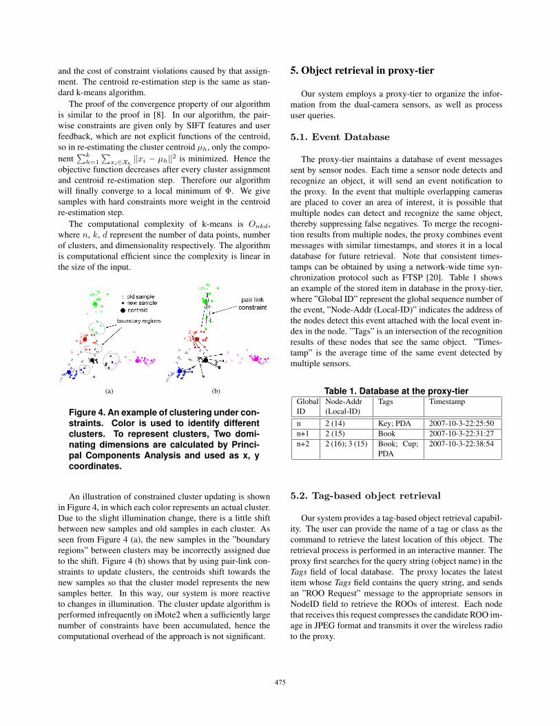
(a) (b)
Figure 4. An example of clustering under con-straints. Color is used to identify differentclusters. To represent clusters, Two domi-nating dimensions are calculated by Princi-pal Components Analysis and used as x, ycoordinates.
An illustration of constrained cluster updating is shownin Figure 4, in which each color represents an actual cluster.Due to the slight illumination change, there is a little shiftbetween new samples and old samples in each cluster. Asseen from Figure 4 (a), the new samples in the ”boundaryregions” between clusters may be incorrectly assigned dueto the shift. Figure 4 (b) shows that by using pair-link con-straints to update clusters, the centroids shift towards thenew samples so that the cluster model represents the newsamples better. In this way, our system is more reactiveto changes in illumination. The cluster update algorithm isperformed infrequently on iMote2 when a sufficiently largenumber of constraints have been accumulated, hence thecomputational overhead of the approach is not significant.
5. Object retrieval in proxy-tier
Our system employs a proxy-tier to organize the infor-mation from the dual-camera sensors, as well as processuser queries.
5.1. Event Database
The proxy-tier maintains a database of event messagessent by sensor nodes. Each time a sensor node detects andrecognize an object, it will send an event notification tothe proxy. In the event that multiple overlapping camerasare placed to cover an area of interest, it is possible thatmultiple nodes can detect and recognize the same object,thereby suppressing false negatives. To merge the recogni-tion results from multiple nodes, the proxy combines eventmessages with similar timestamps, and stores it in a localdatabase for future retrieval. Note that consistent times-tamps can be obtained by using a network-wide time syn-chronization protocol such as FTSP [20]. Table 1 showsan example of the stored item in database in the proxy-tier,where ”Global ID” represent the global sequence number ofthe event, ”Node-Addr (Local-ID)” indicates the address ofthe nodes detect this event attached with the local event in-dex in the node. ”Tags” is an intersection of the recognitionresults of these nodes that see the same object. ”Times-tamp” is the average time of the same event detected bymultiple sensors.
Table 1. Database at the proxy-tierGlobalID
Node-Addr(Local-ID)
Tags Timestamp
n 2 (14) Key; PDA 2007-10-3-22:25:50n+1 2 (15) Book 2007-10-3-22:31:27n+2 2 (16); 3 (15) Book; Cup;
PDA2007-10-3-22:38:54
5.2. Tag-based object retrieval
Our system provides a tag-based object retrieval capabil-ity. The user can provide the name of a tag or class as thecommand to retrieve the latest location of this object. Theretrieval process is performed in an interactive manner. Theproxy first searches for the query string (object name) in theTags field of local database. The proxy locates the latestitem whose Tags field contains the query string, and sendsan ”ROO Request” message to the appropriate sensors inNodeID field to retrieve the ROOs of interest. Each nodethat receives this request compresses the candidate ROO im-age in JPEG format and transmits it over the wireless radioto the proxy.
475
The candidate ROO sent back by the sensor node willbe shown to the user using an easy-to-use GUI. If the usermarks this ROO as ”Valid”, i.e., confirms that it is, in fact,the queried object, the proxy sends an ”Image Request”command to the sensor node and a full image containingthe ROO will be transmitted back to the proxy and shownto the user. Otherwise if the user marks this ROO as ”In-valid”, it means the ROO is not the queried object due to afalse positive. The proxy will continue to search through itsdatabase to locate an older item that matches the user query.This process is repeated until an ROO is accepted by theuser. Such an interactive retrieval approach ensures that wedon’t transfer an entire scene image unless we are sure thatit contains the queried object, thereby saving energy.
The user feedback also provides constraints that can beexploited for better clustering, as described in Section 4.3.2.In addition to the ”Valid/Invalid” marking, users also havethe option of correctly labeling a candidate ROO, or indi-cating if two candidate ROOs are the same object or not.This information is periodically fed back from the proxy tothe appropriate sensor nodes, which use them to update thecluster model.
6. System implementation
This section describes the implementation details of oursystem based on the design discussed in previous sections.
6.1. Hardware implementation
Tier-1: Tier-1 comprises of a Cyclops camera [28] con-nected to a MICAz [1] mote. The Cyclops comprises ofan Agilent ADCM-1700 CMOS camera module, a XilinxFPGA and an ATMega128 microcontroller. The Cyclopscommunicates with MICAz via I2C bus and uses a 2.4GHzCC2420 radio chip as the wireless component.
Tier-2: Tier-2 node comprises of an Enalab camera [2]and an iMote2 [3]. Enalab camera module comprises anOV7649 Omnivision CMOS camera chip, which providescolor VGA (640x480) resolution. The iMote2 comprisesan 18-400MHz Xscale PXA271 processor and a CC2420radio chip. The Enalab camera is connected to the QuickCapture Interface (CIF) on iMote2. To support large imagedata storage, a 1GB external flash memory is attached.
The Tier-1 node and Tier-2 node are connected with atrigger circuit for wakeup, and communicate through theserial port. The Cyclops camera and the Enalab camera aremounted close to each other in order to increase the accu-racy in inter-tier ROO mapping. The sensor nodes are pow-ered by batteries.
Base-station: In the prototype system a PC is used as thebase station. An iMote2 node is connected to the PC andacts as the gateway.
6.2. Software environment
The software environments in our system are different onthe different tiers. In Tier-1, both MICAz and Cyclops runTinyOS 1.1.14. We enhanced the object detection softwareavailable for the Cyclops to perform still object detection.The Tier-2 iMote2 runs Arm-Linux. OpenCV library [4] isused on the iMote2 to facilitate the basic image computa-tions, such as image conversion, transformation and colorhistogram computation. Our SIFT algorithm is based onthe SIFT++ lib, which is a lightweight C++ implementa-tion of SIFT descriptor extraction. The Intel Integrated Per-formance Primitives library (IPP) is used to accelerate dataprocessing. A JPEG compressor was also developed usingIPP lib to compress images. The IEEE 802.15.4 radio pro-tocol is used to communicate among all nodes in the system.
7. Experimental evaluation
We evaluate the performance of our object recognitionsystem through an extensive set of experiments. We firstevaluate the benefits of using a dual-camera sensor node in-stead of a single camera node. We then evaluate the powerconsumption and performance of the object detection, andobject recognition algorithms individually, and finally pro-vide a full system evaluation using multiple cameras in arealistic environment.
There are a number of key parameters in our system: TR,TL
R , THtag for Algorithm 1, and wM , wC , ws for Algo-rithm 2. In all our experiments, TR, TL
R were fixed and setto 0.7 and 0.2 respectively. Our intuition for picking thesevalues was that they screen out the samples in the ”bound-ary regions” (as seen in Figure 4.a). THtag is set to 0.3 inall experiments except in Section 7.5 where we evaluate theimpact of tuning this parameter. For algorithm 2, the exper-imental results are not very sensitive to the parameters wM
and wC , as long as they are assigned a value larger than 10.In our experiment we set wM = wC = 10. ws is also not asensitive parameter and is set to 2.
7.1. Energy cost of object detection
In order to provide a better intuition for the energy gainsoffered by our system, we compare our system with asingle-tier design that keeps iMote2+EnalabCam node al-ways on to perform the detection. In our system, the MI-CAz+CyclopsCam will wake up the iMote2+EnalabCamevery 4 still objects are detected. We also present the powerconsumption for two operational modes of the CyclopsCam- a ”duty-cycle” mode and an ”always on” mode.
Figure 5 (a) shows the power consumption for continu-ous monitoring as a function of the sampling interval. Inthis experiment, no object is detected, i.e., iMote2 does not
476

need to be woken up. As seen from the figure, both op-eration modes of our system consume less energy than thesingle-tier version, clearly demonstrating the benefits of us-ing a tiered system for object detection. The experimentalso reveals that the critical point for choosing betweenthe two modes of the CyclopsCam is around 6 seconds.Thus, when the sampling interval is less than 6 seconds, thealways-on mode of the CyclopsCam is more efficient sincethe energy consumption for transitioning the camera fromsleep to wake state dominates the total power consumption.
Figure 5 (b) evaluates the effect of object detection in-terval (i.e. the average time between two consecutive ob-ject detection events) on the power consumption of the threeschemes. In this experiment, the sampling interval is fixedto 10 seconds. As shown in the figure, if the still object isdetected very frequently, the power consumption of our sys-tem may be a little larger than that of the single-tier version,because of the frequent wake-up overhead of the iMote2node. For most reasonable inter-object intervals, the powerconsumption of the two versions of our system is consider-ably less than that of the single-tier version.
(a)
(b)
Figure 5. Power consumption analysis. (a) Ef-fect of the sampling interval. (b) Effect of ob-ject detection interval.
7.2. Accuracy of object mapping
Obtaining an accurate mapping between the Cyclop-sCam’s ROO and the EnalabCam’s ROO is essential to the
performance of our system. We compare the error in ROOestimation for two schemes: (a) an always-on single-tiersystem that uses the iMote2 and EnalabCam, and (b) oursystem using inter-tier wakeup and ROO mapping. The er-rors are calculated by comparing the object region producedby the algorithms to those labeled manually. The exper-imental results in Table 2 show that our system has onlymarginal higher error (less than two pixels along each axis)than a single-tier system that uses a high resolution camera.In addition, the absolute error is less than three pixels oneach axis.
Table 2. Error analysis on object detection.Errors are measured in pixel.
Center Error Width error Height ErrorTest Avg (Var) Avg (Var) Avg (Var)EnalabCam 1.04 (0.88) 1.70 (4.90) 1.30 (4.46)DualCam 2.47 (2.08) 2.84 (4.13) 2.91 (6.07)
7.3. Comparison between color and SIFT
In this section, we demonstrate the accuracy and en-ergy benefits of using the Color and SIFT features in a cas-cading manner for object recognition (described in Section4.2.2). Table 3 compares the performance of three differ-ent recognition methods, only Color features; only SIFTfeatures, and the cascading combination of the two. Weuse two metrics to evaluate the schemes - rate and latency.The ”rate” metric shows the percentage of correctly recog-nized objects, and the ”latency” metric shows the amount oftime taken by the iMote2 node for object recognition, whichin turn corresponds to the energy consumption for recogni-tion. Five common objects are used in this test: book, cup,keyring, PDA, and TV remote control. These are all com-mon objects that are easy to lose.
We tested the three methods with a training set and atest set. The training set contains 50 samples. The testset, FIXED-ILLUM, contains 100 samples under the samelighting conditions as in the training set. The set VARY-ILLUM contains 100 samples where we introduced illumi-nation changes by switching off one of the three ceilinglights in the room. Samples are collected by placing theobjects in different locations and with different poses on atable. We first train the clusters by using the training dataset,and then classify the two test sets respectively.
Table 3 shows that the recognition rate by using a combi-nation of Color and SIFT features has higher accuracy thanusing the features individually. When illumination changesare present, the improvement in accuracy over color alone is17%. The computation time for processing is significantly
477

greater than for a method that just uses color features, butis only a third of the time required for processing the higheraccuracy SIFT descriptors. This is because our algorithmneeds to run the SIFT algorithm only on roughly 20-40% ofthe samples. Note that cluster updates were not performedin this experiment.
Table 3. Comparison on recognition meth-ods (The power consumption during objectrecognition is 681mW)
FIXED-ILLUM VARY-ILLUMMethods Rate Latency Rate Latency1. Color 84% 0.0034s 63% 0.0032s2. SIFT 83% 6.49s 75% 6.17s3. Color + SIFT 91% 2.07s 80% 2.96s
7.4. Benefits of using constraints
We now evaluate the benefits of using pair-link con-straints to improve clustering results. In this experiment,we collect another test dataset, VARY-ILLUM-1, that con-tains 100 samples under the same illumination conditionsas in VARY-ILLUM. We then evaluate whether the recogni-tion rate on VARY-ILLUM-1 improves as a result of refine-ment of the clusters with constraints that are obtained fromVARY-ILLUM in the previous experiment. Table 4 showsthe results of this experiment. The ”No constraint” columnshows the results using only standard k-means without con-straints, and the ”Using constraint” column shows the re-sults of our constrained k-means algorithm with refinementusing constraints derived from VARY-ILLUM (described inSection 4.3). As seen from Table 4, the use of constraintsimproves the recognition results by 10% when only colorfeatures are used, and by 6% when both color and SIFTfeatures are used. The refinement of clusters also improvesthe latency required to perform the object recognition byabout 20%, since the clusters are more accurate and hencethe SIFT recognition algorithm is invoked fewer times.
Table 4. Improvements on using constraints(The power consumption during objectrecognition is 681mW)
VARY-ILLUM-1Recognition methods No constraint Using constraintColor Rate 68% 78%Color + SIFT Rate 77% 83%
Latency 2.89s 2.24s
The recognition results above are all produced by a sin-gle camera node. We also evaluate the benefits of placingmultiple sensor nodes with overlapping coverage for objectrecognition. In our experiment we evaluated the recognitionrate using two camera views and found that the recognitionrate improves from 82% (single view) to 86% (two views).
7.5. System performance on object retrieval
We now evaluate the overall performance of our objectretrieval system using an experiment in a real room envi-ronment with multiple sensor nodes. In this experiment, weplaced 5 dual-camera nodes in a room so that the FOVs ofthese nodes cover most of the area in which human activitymay happen. The cameras are placed in an ad-hoc manner,so some cameras have overlaps in their field of view. Fig-ure 6 shows the deployment of the camera network. We usethe same object set as previous experiments: book, cup, keyring, PDA, and TV remote control. In this experiment, ob-jects are randomly placed and removed from the monitoredarea. Queries for each object are generated after roughlyevery 20-25 object placements events.
Figure 6. Camera network deployment, a topview map.
Table 5 gives the results from this experiment. The firstcolumn labeled ”Correct/Total” stands for the ratio of num-ber of correctly retrieved images to the number of queries.A correct retrieval is the case where the system returns thelatest scene image containing the queried object. ”AverageROO Transmitted” denotes the average number of candi-date regions that need to be transmitted to get the retrievalresult. As seen from the table, in the absence of user feed-back, our system achieves 90% accuracy in ROO retrieval,with less than four candidate regions retrieved per correctretrieval. If users provide additional feedback by labelingreturned candidate ROOs, the accuracy increases by 5% to95%, and the average number of ROOs need to be transmit-ted for each query is reduced from 3.6 to 2.5 (a reduction of7KB in bytes transmitted).
Impact of Tagging Threshold: The correct rate and thenumber of ROOs that are transmitted are sensitive to the
478
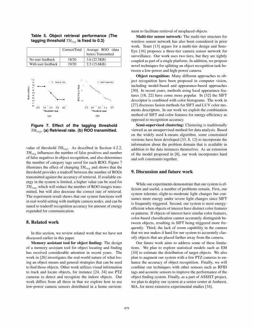
Table 5. Object retrieval performance (Thetagging threshold THtag is fixed to 0.3)
Correct/Total Average ROO (databytes) Transmitted
No user feedback 18/20 3.6 (22.5KB)With user feedback 19/20 2.5 (15.6KB)
(a) (b)
Figure 7. Effect of the tagging thresholdTHtag. (a) Retrieval rate. (b) ROO transmitted.
value of threshold THtag . As described in Section 4.2.2,THtag influences the number of false positives and numberof false negatives in object recognition, and also determinesthe number of category tags saved for each ROO. Figure 7illustrates the effect of changing THtag and shows that thethreshold provides a tradeoff between the number of ROOstransmitted against the accuracy of retrieval. If available en-ergy in the system is limited, a higher value can be used forTHtag , which will reduce the number of ROO images trans-mitted, but will also decrease the correct rate of retrieval.The experiment result shows that our system functions wellin real world setting with multiple camera nodes, and can betuned to tradeoff recognition accuracy for amount of energyexpended for communication.
8. Related work
In this section, we review related work that we have notdiscussed earlier in this paper.
Memory assistant tool for object finding: The designof a memory assistant tool for object locating and findinghas received considerable attention in recent years. Thework in [26] investigates the real-world nature of what los-ing an object means and general strategies that can be usedto find those objects. Other work utilizes visual informationto track and locate objects, for instance [24, 34] use PTZcameras to detect and recognize the indoor objects. Ourwork differs from all these in that we explore how to uselow-power camera sensors distributed in a home environ-
ment to facilitate retrieval of misplaced objects.Multi-tier sensor network: The multi-tier structure for
wireless sensor network has also been considered in priorwork. Tenet [13] argues for a multi-tier design and Sens-Eye [16] proposes a three-tier camera sensor network forsurveillance. Our work uses two tiers, but they are tightlycoupled as part of a single platform. In addition, we proposenovel techniques for splitting an object recognition task be-tween a low-power and high-power camera.
Object recognition: Many different approaches to ob-ject recognition have been proposed in computer vision,including model-based and appearance-based approaches[30]. In recent years, methods using local appearance fea-tures [18, 22] have come more popular. In [32] the SIFTdescriptor is combined with color histograms. The work in[27] discusses fusion methods for SIFT and LUV color mo-ments descriptors. In our work we exploit the combinationmethod of SIFT and color features for energy-efficiency asopposed to recognition accuracy.
Semi-supervised clustering: Clustering is traditionallyviewed as an unsupervised method for data analysis. Basedon the widely used k-means algorithm, some constrainedversions have been developed [33, 8, 12] to incorporate theinformation about the problem domain that is available inaddition to the data instances themselves. As an extensionof the model proposed in [8], our work incorporates hardand soft constraints together.
9. Discussion and future work
While our experiments demonstrate that our system is ef-ficient and useful, a number of problems remain. First, oursystem tolerates slight-to-moderate light changes but con-sumes more energy under severe light changes since SIFTis frequently triggered. Second, our system is most energy-efficient when objects of interest have distinct color featuresor patterns. If objects of interest have similar color features,color-based classification cannot accurately distinguish be-tween objects, resulting in SIFT being triggered more fre-quently. Third, the lack of zoom capability in the camerathat we use makes it hard for our system to accurately clas-sify objects that are placed farther away from the camera.
Our future work aims to address some of these limita-tions. We plan to explore statistical models such as EM[10] to estimate the distribution of target objects. We alsoplan to augment our system with a few PTZ cameras to en-hance the accuracy of object recognition. Finally, we willcombine our techniques with other sensors such as RFIDtags and acoustic sensors to improve the performance of theobject finding system. Finally, as a part of ASSIST project,we plan to deploy our system at a senior center at Amherst,MA, for more extensive experimental studies [34].
479
10. Conclusion
This paper presents the design and implementation ofan indoor object retrieval system using a network of dual-camera wireless nodes, each of which combine multiplecameras with complementary capabilities. Our system pro-poses a number of novel techniques including: (a) the useof the low-power camera both for still object detection andregion-of-object estimation, (b) the use of two different vi-sual features - color histogram and SIFT descriptors - forenergy-efficient yet accurate object recognition, and (c) re-finement of clusters for more accurate classification usingpairwise constraints from SIFT matching and user feed-back. Our experimental results demonstrate that the systemis energy efficient, computationally efficient, and accurate.
References
[1] Crossbow wireless sensor platform. http://www.xbow.com/.[2] Enalab camera. http://enaweb.eng.yale.edu/drupal/.[3] Intel mote2 platform. http://www.xbow.com/products.[4] Intel open source computer vision library.
http://www.intel.com/technology/computing/opencv/.[5] Cyclops platform. http://enaweb.eng.yale.edu/drupal/. 2007.[6] H. Aghajan, J. Augusto, C. Wu, P. McCullagh, and J. Walk-
den. Distributed vision-based accident management for as-sisted living. Int. Conf. on Smart homes and health Telemat-ics, 2007.
[7] E. Ardizzone, M. Cascia, G. Re, and M. Ortolani. An in-tegrated architecture for surveillance and monitoring in anarchaeological site. ACM Int. Workshop on Video Surveil-lance and Sensor Networks, 2005.
[8] S. Basu, A. Banerjee, and R. J. Mooney. Active semi-supervision for pairwise constrained clustering. Proc. of the4th SIAM Int. Conf. on Data Mining, 2004.
[9] G. Borriello, W. Brunette, M. Hall, C. Hartung, andC. Tangney. Reminding about tagged objects using passiverfids. Proc. of the 8th Ubicomp Conference, 2006.
[10] A. Dempster, N. Laird, and D. Rubin. Maximum likelihoodfrom incomplete data via the em algorithm. Journal of theRoyal Statistical Society, Series B, 1977.
[11] B. Funt and G. Finlayson. Color constant color indexing.IEEE Trans. PAMI, May 1995.
[12] J. Gao, P.-N. Tan, and H. Cheng. Semi-supervised clusteringwith partial background information. Proc. of the 6th SIAMInt. Conf. on Data Mining, 2006.
[13] O. Gnawali, B. Greenstein, K. Jang, A. Joki, J. Paek,M. Vieira, D. Estrin, R. Govindan, and E. Kohler. The tenetarchitecture for tiered sensor networks. ACM Conf. on Em-bedded Networked Sensor Systems, 2006.
[14] S. Hengstler, D. Prashanth, S. Fong, and H. Aghajan. Mesh-eye: a hybrid-resolution smart camera mote for applicationsin distributed intelligent surveillance. Int. Conf. on Informa-tion Processing in Sensor Networks, SPOTS, 2007.
[15] J. Kientz, S. Patel, A. Tyebkhan, B. Gane, J. Wiley, andG. Abowd. Where’s my stuff?: design and evaluation ofa mobile system for locating lost items for the visually im-paired. ACM conf. on Computers and accessibility, 2006.
[16] P. Kulkarni, D. Ganesan, P. Shenoy, and Q. Lu. Senseye: Amulti-tier camera sensor network. ACM Multimedia, 2005.
[17] X. Liu, M. Corner, and P. Shenoy. Ferret: Rfid localizationfor pervasive multimedia. Ubicomp Conference, 2006.
[18] D. Lowe. Distinctive image features from scale-invariantkeypoints. Int. Journal of Computer Vision, 2004.
[19] D. Malan, T. Fulford-Jones, M. Welsh, and S. Moulton.Codeblue: An ad hoc sensor network infrastructure foremergency medical care. Int. Workshop on Wearable andImplantable Body Sensor Networks, 2004.
[20] M. Marti, B. Kusy, G. Simon, and A. Ldeczi. The floodingtime synchronization protocol. ACM Conf. on EmbeddedNetworked Sensor Systems, 2004.
[21] G. Mathur, P. Desnoyers, D. Ganesan, and P. Shenoy. Ultra-low power data storage for sensor networks. Int. Conf. onInformation Processing in Sensor Networks, SPOTS, 2006.
[22] K. Mikolajczyk and C. Schmid. A performance evaluationof local descriptors. IEEE Trans. Pattern Analysis and Ma-chine Intelligence, 2005.
[23] T. Nakada, H. Kanai, and S. Kunifuji. A support systemfor finding lost objects using spotlight. Int. conf. on MobileHuman Computer Interaction, 2005.
[24] R. Nelson and I. Green. Tracking objects using recognition.Proc. Int. Conf on Pattern Recognition, 2002.
[25] R. Orr, R. Raymond, J. Berman, and A. Seay. A system forfinding frequently lost objects in the home. Georgia TechGVU Technical Report: GIT-GVU-99-24, 1999.
[26] R. Peters, R. Pak, G. Abowd, A. Fisk, and W. Rogers. Find-ing lost objects: Informing the design of ubiquitous com-puting services for the home. Georgia Tech GVU TechnicalReport: GIT-GVU-04-01, 2004.
[27] P. Quelhas and J.-M. Odobez. Natural scene image modelingusing color and texture visterims. ACM Int. Conf. on Imageand Video Retrieval, 2006.
[28] M. Rahimi, R. Baer, J. Warrior, D. Estrin, and M. Srivastava.Cyclops: In situ image sensing and interpretation in wirelesssensor networks. ACM Conf. on Embedded Networked Sen-sor Systems, 2005.
[29] P. Schgerl, R. Sorschag, W. Bailer, and G. Thallinger. Objectre-detection using sift and mpeg-7 color descriptors. Int.Workshop Multimedia Content Analysis and Mining, 2007.
[30] C. Schmid and R. Mohr. Local greyvalue invariants for im-age retrieval. IEEE Trans. PAMI, 1997.
[31] T. Teixeira, D. Lymberopoulos, E. Culurciello, Y. Aloi-monos, and A. Savvides. A lightweight camera sensor net-work operating on symbolic information. Proc. of 1st Work-shop on Distributed Smart Cameras, 2006.
[32] J. van de Weijer and C. Schmid. Coloring local feature ex-traction. European Conf. on Computer Vision, 2006.
[33] K. Wagstaff, C. Cardie, S. Rogers, and S. Schroedl. Con-strained k-means clustering with background knowledge.Int. Conf. on Machine Learning, 2001.
[34] A. Williams, D. Xie, S. Ou, R. Grupen, A. Hanson, andE. Riseman. Distributed smart cameras for aging in place.Proc. of 1st Workshop on Distributed Smart Cameras, 2006.
[35] P. Wilson, D. Prashanth, and H. Aghajan. Utilizing rfidsignaling scheme for localization of stationary objects andspeed estimation of mobile objects. IEEE Int. Conf. onRFID, March 2007.
480