design and implementation of a practical flex paging … · table 2-2 relative signal strength for...
TRANSCRIPT

DESIGN AND IMPLEMENTATION OF APRACTICAL FLEX TM PAGING DECODER
byScott Lindsey McCulley
Thesis submitted to the Faculty of the Virginia Polytechnic Institute and State University inpartial fulfillment of the requirement of the degree of
Master of Sciencein
Electrical Engineering
Dr. Theodore S. Rappaport, Chair
Dr. Jeffrey ReedDr. Brian D. Woerner
October 24, 1997Blacksburg, Virginia
Keywords: Bit-Error-Rate (BER) Measurements, Bose-Chaudhuri-Hocquenhem (BCH), FLEX,Paging Decoder, Frequency Shift Keying (FSK)
Copyright 1997, Scott Lindsey McCulley

Design and Implementation of a Practical FLEX Paging Decoder
by
Scott McCulley
Theodore S. Rappaport, Chairman
Electrical Engineering
(ABSTRACT)
The Motorola Inc. paging protocol FLEX is discussed. The design and construction of a FLEX
paging protocol decoder is discussed in detail. It proposes a decoding solution that includes a
radio frequency (RF) receiver and a decoder board. The RF receiver will be briefly discussed.
The decoder design is the main focus of this thesis as it transforms the RF frequency modulated
(FM) data from the receiver and converts it to FLEX data words. The decoder is designed to
handle bit sampling, bit clock synchronization, FLEX packet detection, and FLEX data word
collection. The FLEX data words are then sent by the decoder to an external computer through a
serial link for bit processing and storage. A FLEX transmitter will send randomly generated data
so that a bit error rate (BER) calculation can be made at a PC. Each receiver’s noise power and
noise bandwidth will be measured so that noise spectral density may be calculated. A complete
measurement set-up will be shown on how these noise measurements are made. The BER at a
known power level is recorded. This enables Eb/No curves to be generated so that results of the
decoding algorithm may be compared. This is performed on two different receivers.

Grayson Wireless iii
Acknowledgments
I wish to express my deep appreciation to Dr. Theodore S. Rappaport for acting as my advisor
and for his motivation, guidance, and persistence in seeing that I complete this work. I also wish
to thank Dr. Jeffrey Reed and Dr. Brain D. Woerner for serving on my committee.
I would also like to thank Grayson Wireless whose resources made this work possible. A special
thanks goes to several managers: Ken Talbott, Kent Bell, Steve Thompson, and Sam Serio and to
the president Terry Garner.
I would also like to thank MPRG who gave me my first taste of research when I was an
undergraduate in 1989. I saw the program grow up to become a nationally recognized research
group, and I feel proud to say that I was apart of it.
Lastly, I would like to express my deep love to my wife, Ann, and my family for whose support
was needed to complete this long journey.

Grayson Wireless iv
Table of Contents
Abstract ii
Acknowledgments iii
Table of Contents iv
List of Figures vii
List of Tables ix
1. Introduction 1
2. FLEX Protocol 4
2.1 Overview of FLEX Protocol .................................................................................................. 4
2.2 FLEX Data Rate and Modulation .......................................................................................... 5
2.3 FLEX Data Format................................................................................................................. 6
2.3.1 Frame Format .................................................................................................................. 8
2.3.2 Block Interleaving ........................................................................................................... 9
2.3.3 Codeword ...................................................................................................................... 10
2.3.4 Coding Format............................................................................................................... 10
2.4 Fading Tolerance.................................................................................................................. 12
2.5 FLEX and POCSAG mixed................................................................................................. 13
3. Receiver and Decoder Design 15
3.1 Receiver ............................................................................................................................... 15
3.2 Decoder ................................................................................................................................ 18
3.3 Microprocessor software implementation............................................................................ 25
Grayson Wireless v
3.4 BER Measurements ............................................................................................................. 29
4. Measurements 32
4.1 Linear Receiver .................................................................................................................... 32
4.2 Equivalent noise bandwidth................................................................................................. 34
4.3 Noise power ......................................................................................................................... 35
4.4 Cable loss............................................................................................................................. 36
4.5 FLEX data............................................................................................................................ 36
5. Results 40
5.1 Linear measurement............................................................................................................. 40
5.2 Cable loss measurement....................................................................................................... 40
5.3 Noise measurements ............................................................................................................ 41
5.4 FLEX Data Measurements................................................................................................... 42
5.5 Analysis................................................................................................................................ 45
6. Conclusion 46
7. References 47
8. Appendix - Code Listings 49
9. Vita 66
Grayson Wireless vi
List of Figures
Figure 2-1 FLEX 2-FSK bit pattern with frequency deviation....................................................... 5
Figure 2-2 FLEX 4-FSK bit pattern with frequency deviation....................................................... 6
Figure 2-3 FLEX data organized in cycles and frames .................................................................. 7
Figure 2-4 Frame format ................................................................................................................ 8
Figure 2-5 Block interleaving for 1600 bps ................................................................................... 9
Figure 2-6 FLEX codeword.......................................................................................................... 10
Figure 2-7 FLEX coding format................................................................................................... 11
Figure 3-1 Receiver block diagram .............................................................................................. 16
Figure 3-2 Ideal frequency vs. FM discriminated voltage............................................................ 18
Figure 3-3 Decoder discrimination............................................................................................... 19
Figure 3-4 Peak + and Peak - Circuits.......................................................................................... 20
Figure 3-5 Frequency deviation, threshold voltage level, and 4-FSK symbol relationship ......... 21
Figure 3-6 Resistor divider used to detect threshold voltage levels............................................. 23
Figure 3-7 Limited Data into Microprocessor.............................................................................. 23
Figure 3-8 Interrupt processing block diagram ............................................................................ 26
Figure 3-9 Main processing block diagram.................................................................................. 27
Figure 4-1 Linearity measurement................................................................................................ 33
Figure 4-2 Equivalent noise bandwidth measurement ................................................................. 35

Grayson Wireless vii
Figure 4-3 Cable loss measurement ............................................................................................. 36
Figure 4-4 FLEX data measurement ............................................................................................ 37
Figure 4-5 FLEX data measurement block diagram..................................................................... 38
Figure 5-1 AS4927 Graph of BER versus Eb/No.......................................................................... 43
Figure 5-2 AS4928 Graph of BER versus Eb/No.......................................................................... 44
Grayson Wireless viii
List of Tables
Table 2-1 Codewords per paging type.......................................................................................... 12
Table 2-2 Relative signal strength for 99% success rate of 80 characters alphanumeric message13
Table 4-1 HP8591A spectrum analyzer setup .............................................................................. 34
Table 4-2 Format of FLX4nnnn.RND files................................................................................... 37
Table 4-3 Format of each frame in RrF4nnnn.aaa files................................................................ 39
Table 5-1 Linear measurement ..................................................................................................... 40
Table 5-2 Cable loss measurement of 1 to 4 splitter and cables................................................... 41
Table 5-3 Noise measurement ...................................................................................................... 41
Table 5-4 AS4927 FLEX measurement ....................................................................................... 42
Table 5-5 AS4928 FLEX measurement ....................................................................................... 42
Table 5-6 AS4927 BER versus Eb/No........................................................................................... 43
Table 5-7 AS4928 BER versus Eb/No........................................................................................... 44
Design and Implementation of a Practical FLEX Paging Decoder
Grayson Wireless 1
Chapter 1
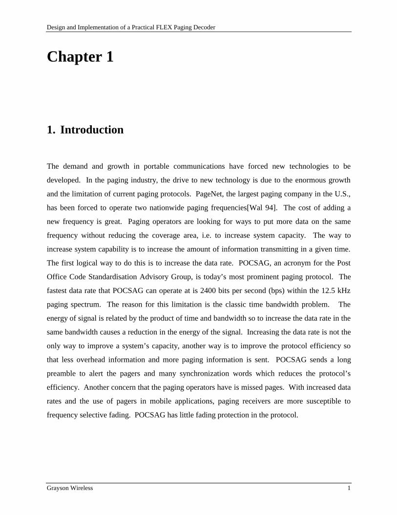
1. Introduction
The demand and growth in portable communications have forced new technologies to be
developed. In the paging industry, the drive to new technology is due to the enormous growth
and the limitation of current paging protocols. PageNet, the largest paging company in the U.S.,
has been forced to operate two nationwide paging frequencies[Wal 94]. The cost of adding a
new frequency is great. Paging operators are looking for ways to put more data on the same
frequency without reducing the coverage area, i.e. to increase system capacity. The way to
increase system capability is to increase the amount of information transmitting in a given time.
The first logical way to do this is to increase the data rate. POCSAG, an acronym for the Post
Office Code Standardisation Advisory Group, is today’s most prominent paging protocol. The
fastest data rate that POCSAG can operate at is 2400 bits per second (bps) within the 12.5 kHz
paging spectrum. The reason for this limitation is the classic time bandwidth problem. The
energy of signal is related by the product of time and bandwidth so to increase the data rate in the
same bandwidth causes a reduction in the energy of the signal. Increasing the data rate is not the
only way to improve a system’s capacity, another way is to improve the protocol efficiency so
that less overhead information and more paging information is sent. POCSAG sends a long
preamble to alert the pagers and many synchronization words which reduces the protocol’s
efficiency. Another concern that the paging operators have is missed pages. With increased data
rates and the use of pagers in mobile applications, paging receivers are more susceptible to
frequency selective fading. POCSAG has little fading protection in the protocol.

Design and Implementation of a Practical FLEX Paging Decoder
Grayson Wireless 2
Motorola Inc. has developed a new paging protocol called FLEX 1 to address these concerns.
Paging operators are looking at FLEX because it is a faster data rate system that allows more
users within the same bandwidth. FLEX can operate at 6400 bps with bandwidth efficiency
similar to POCSAG 2400. FLEX is also a more protocol efficient paging standard that does not
have much overhead information. It also has fading tolerance through data interleaving. The
system was designed for flexibility with standard Alpha, Numeric, and Tone pages but also
allows for broadcast messages, direct binary messages, and other expandable features. The latest
protocols from Motorola Paging Division is the release of it’s new two-way paging technologies
ReFLEX25, ReFLEX50, and InFLEXion.2 All of these build on the original FLEX
protocol.
This thesis will discuss the design and construction of a FLEX paging protocol decoder. It
proposes a decoding solution that includes a radio frequency (RF) receiver and a decoder board.
The RF receiver will be discussed. The decoder design is the main focus of this thesis as it
transforms the RF frequency modulated (FM) data from the receiver and converts it to FLEX
data words. The decoder is designed to handle bit sampling, bit clock synchronization, FLEX
packet detection, and FLEX data word collection. The FLEX data words are then sent by the
decoder to an external computer through a serial link for bit processing and storage.
The receiver and decoder have been implemented in a commercial paging receiver product by
Grayson Wireless. The 929 MHz to 932 MHz Paging Receiver (Grayson Part Number
GMR120) is the RF receiver that the decoder needs to operate. The Paging Decoder (Grayson
Part Number GMD200) is a paging decoder that can decode POCSAG, FLEX, GOLAY, and
NEC. This thesis details the FLEX decoding portion of the GMD200 and the decoding of the
other standards can be logically related since FLEX is the most difficult. The performance of the
decoder design is measured using the Wireless Measurement System (Grayson Part Number
GMM1000) equipped with three GMR120 and three GMD200. A HP8648A Signal Generator
with the FLEX encoder option is used as the signal source. The GMM1000 is a measurement
1 FLEX is a registered trademark of Motorola, Inc.2 ReFLEX25, ReFLEX50, and InFLEXion are registered trademarks of Motorola, Inc.

Design and Implementation of a Practical FLEX Paging Decoder
Grayson Wireless 3
mainframe that allows up to four pairs of receivers and decoders to communicate with a PC
through a high speed serial port.
Design and Implementation of a Practical FLEX Paging Decoder
Grayson Wireless 4
Chapter 2
2. FLEX Protocol
2.1 Overview of FLEX Protocol
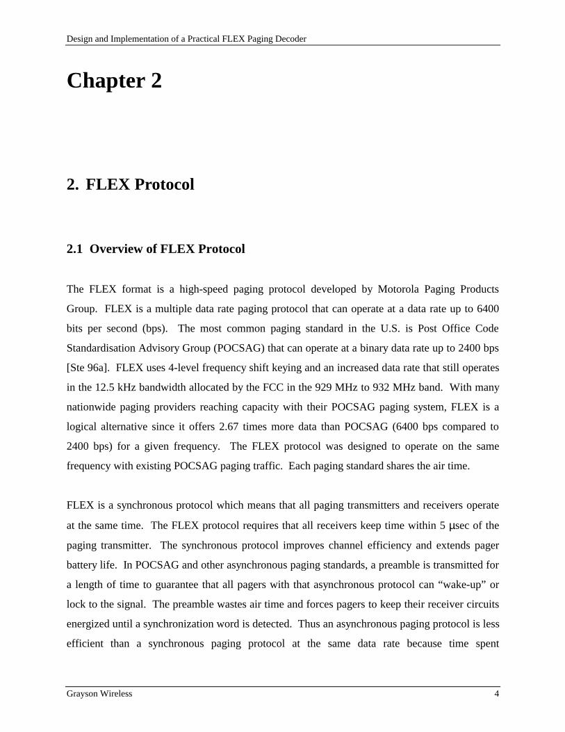
The FLEX format is a high-speed paging protocol developed by Motorola Paging Products
Group. FLEX is a multiple data rate paging protocol that can operate at a data rate up to 6400
bits per second (bps). The most common paging standard in the U.S. is Post Office Code
Standardisation Advisory Group (POCSAG) that can operate at a binary data rate up to 2400 bps
[Ste 96a]. FLEX uses 4-level frequency shift keying and an increased data rate that still operates
in the 12.5 kHz bandwidth allocated by the FCC in the 929 MHz to 932 MHz band. With many
nationwide paging providers reaching capacity with their POCSAG paging system, FLEX is a
logical alternative since it offers 2.67 times more data than POCSAG (6400 bps compared to
2400 bps) for a given frequency. The FLEX protocol was designed to operate on the same
frequency with existing POCSAG paging traffic. Each paging standard shares the air time.
FLEX is a synchronous protocol which means that all paging transmitters and receivers operate
at the same time. The FLEX protocol requires that all receivers keep time within 5 µsec of the
paging transmitter. The synchronous protocol improves channel efficiency and extends pager
battery life. In POCSAG and other asynchronous paging standards, a preamble is transmitted for
a length of time to guarantee that all pagers with that asynchronous protocol can “wake-up” or
lock to the signal. The preamble wastes air time and forces pagers to keep their receiver circuits
energized until a synchronization word is detected. Thus an asynchronous paging protocol is less
efficient than a synchronous paging protocol at the same data rate because time spent
Design and Implementation of a Practical FLEX Paging Decoder
Grayson Wireless 5
transmitting a preamble in an asynchronous protocol can be time used to transmit revenue
generating data. The FLEX pager uses its low power CMOS circuit to keep time and only during
its time slot does it power on the receiver for a short time to search for a synchronization word.
The synchronous FLEX paging data is organized so that GPS clock accuracy can be used at the
transmitter. [Wal 94]
2.2 FLEX Data Rate and Modulation
FLEX can operate at three data rates: 1600 bits per second (bps), 3200 bps, and 6400 bps. The
modulation used is both two level frequency shift keying (2-FSK) and four level frequency shift
keying (4-FSK). The 6400 bps FLEX is sent with 4-FSK, the 3200 bps can be sent either 2-FSK
or 4-FSK, and the 1600 bps is always sent using 2-FSK. Thus there are only two baud rates in
FLEX: 1600 baud and 3200 baud, where the number of bits in a symbol can be one or two. [Wal
94]
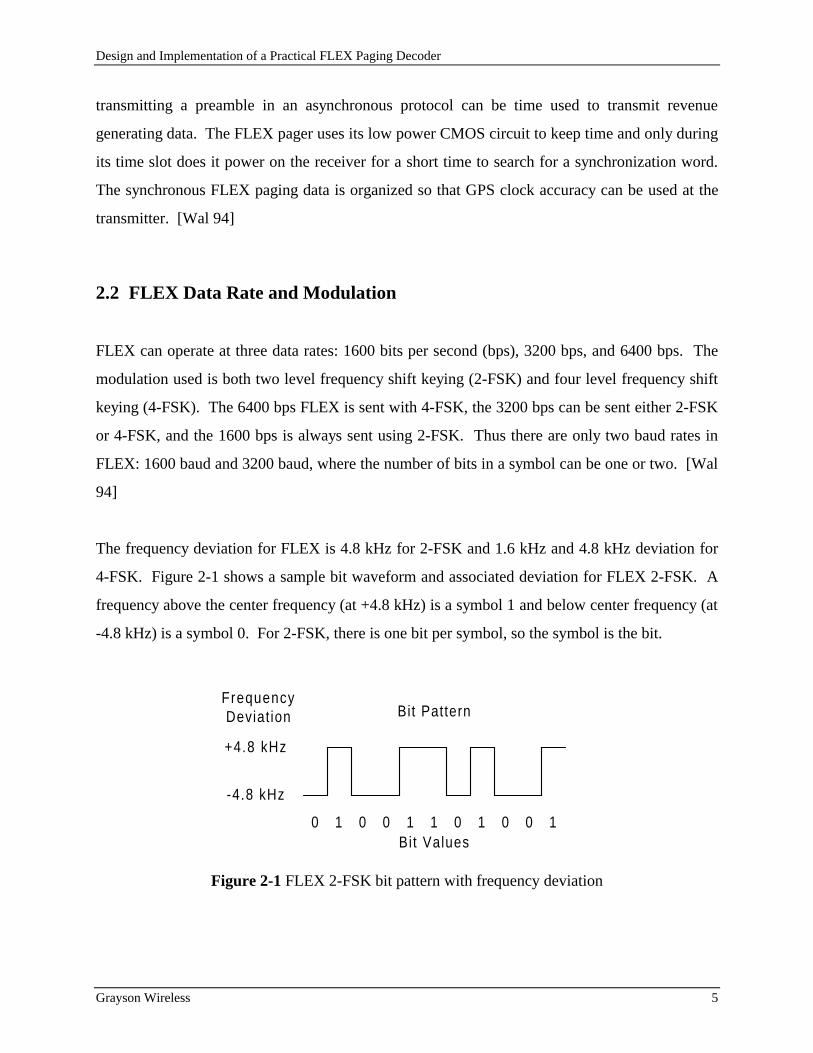
The frequency deviation for FLEX is 4.8 kHz for 2-FSK and 1.6 kHz and 4.8 kHz deviation for
4-FSK. Figure 2-1 shows a sample bit waveform and associated deviation for FLEX 2-FSK. A
frequency above the center frequency (at +4.8 kHz) is a symbol 1 and below center frequency (at
-4.8 kHz) is a symbol 0. For 2-FSK, there is one bit per symbol, so the symbol is the bit.
+4.8 kHz
-4.8 kHz
FrequencyDeviat ion Bit Pattern
0 0 0 0 0 011 1 1 1Bit Values
Figure 2-1 FLEX 2-FSK bit pattern with frequency deviation

Design and Implementation of a Practical FLEX Paging Decoder
Grayson Wireless 6
The 4-FSK data is transmitted using a Gray-code [Cou 90] which means that the difference
between any two adjacent levels or symbols can only have a one bit difference. The reason for
this code is so that if a frequency deviation is close to the boundary and it’s decoded to the wrong
symbol only one bit will be wrong. The symbol order from -4.8 kHz to +4.8 kHz is 00, 01, 11,
10. Figure 2-2 displays a sample bit pattern with the appropriate symbol for FLEX 4-FSK. Also
included is the corresponding frequency deviation. The difference between any adjacent symbols
is 3.2 kHz.
+4.8 kHz
-4.8 kHz
FrequencyDeviat ion Bit Pattern
-1.6 kHz
Symbol Values
+1.6 kHz
00 10 01 00 10 001111 01 10 01
Figure 2-2 FLEX 4-FSK bit pattern with frequency deviation
2.3 FLEX Data Format
Figure 2-3 shows how the FLEX data is organized from cycles to frames. One hour contains 15
cycles. Cycles are numbered 0 to 14. Each cycle is 4 minutes long and contains 128 frames.
Frames are number 0 to 127. Each frame is 1.875 seconds long. The frame is the smallest part
of information that can be sent, but every frame in every cycle does not need to be transmitted.
Although to keep all the FLEX pagers synchronized, every pager must receive one frame every 4
minutes. This “tickling” of the pagers keeps their clocks synchronized and allows them to
“wake-up” at the appropriate time. Thus the minimum amount of FLEX activity requires a

Design and Implementation of a Practical FLEX Paging Decoder
Grayson Wireless 7
FLEX pager to receive the same numbered frame within two consecutive cycles. For example, if
cycle 0 frame 30 is transmitted, then the next frame that must be transmitted is cycle 1 frame 30.
NOTE: The first release of Motorola FLEX pager, the PRO ENCORE, required that one frame
be received every two minutes. This requires a minimum of two frames a cycle separated by 64
frames.
Cycle 0 Cycle 14Cycle 1
15 Cycles = 1 Hour
128 Frames = 4 Minutes
Frame 0 Frames 127Frame 1
1.875 Seconds
Figure 2-3 FLEX data organized in cycles and frames
The pager and paging terminal are set up to begin receiving and transmitting one frame out of
every 2x consecutive frames, where x can be 0 to 7. Thus when x is 0, continuous FLEX data
frames are received. When x is 7, there is one frame received out of every 128 frames, and it is
the same numbered frame. For example, if frame number 0 is received and frame numbers 1
through 127 are not received and frame number 0 of the next cycle is received, then x is 7. This
example is the minimum amount of FLEX activity required so that a pager will remain
synchronized.

Design and Implementation of a Practical FLEX Paging Decoder
Grayson Wireless 8
2.3.1 Frame Format
The format of each frame is shown in Figure 2-4 [Ste 96b]. Each frame contains a
synchronization period (Sync) of 115 ms and then 11 blocks of data with each block having a
duration of 160 ms. Blocks are numbered 0 to 10.
Sync Block 0
Sync 1 Sync 2
115 ms
25 ms90 ms
Block 1 Block 10
160 ms
1875 ms
FrameInfo
Figure 2-4 Frame format
The synchronization period contains two synchronization periods. The first synchronization
period (Sync1 and Frame Info) is always sent at 1600 bps. Due to the proprietary nature of the
FLEX protocol, the exact format of Sync1, Frame Info, and Sync2 cannot be discussed. Only
important facts about each one will be discussed here so that a complete overview of the protocol
can be given. Sync1 contains two 32-bit synchronization words that are separated by 16 dotting
bits. These words are unique and identify the baud rate (1600 or 3200) and the modulation type
(2-FSK or 4-FSK) of Sync2 and the data blocks. The frame information which is between Sync1
and Sync2 identifies the current frame number and cycle number. The total number of bits in
Sync1 and Frame Info are 144 bits @ 1600 bps which is 90 ms in duration. Following Frame
Info is the second synchronization period (Sync 2) which is 25 ms long. This synchronization is
designed to train the receiver and decoder to the new modulation and baud rate.

Design and Implementation of a Practical FLEX Paging Decoder
Grayson Wireless 9
2.3.2 Block Interleaving
Each block contains 8, 16, or 32 codewords of data for 1600 bps, 3200 bps, or 6400 bps,
respectively. Each codeword is 32 bits long and contains information and parity bits. The
structure of these codewords will be discussed in the next section. This section only discusses
how the bits in the codewords are interleaved before transmission. The interleaving process is
performed such that the first data bit in all the codewords are transmitted first, then the second
data bit in all the codewords are transmitted, and this process continues until the 32nd data bit in
all the codewords are transmitted. Figure 2-5 is the block interleaving for 1600 bps data and
illustrates the order the bits are transmitted. The 32-bit codewords are arranged in rows and the
bits are transmitted column by column. Each column requires 5 ms to transmit.
32
Codeword 01 10 20
Codeword 1
Codeword 2
Codeword 3
Codeword 4
Codeword 5
Codeword 6
Codeword 7
5 ms
Figure 2-5 Block interleaving for 1600 bps
The transmission of the data bits still follows the modulation type and baud rate. For 2-FSK, the
bit transmission is straight forward. Each bit is mapped to one of two frequencies for the period
of the baud rate. For 4-FSK, two bits, each bit from the same column of an adjacent codeword,
are mapped to one of four frequencies for the period of the baud rate.
Design and Implementation of a Practical FLEX Paging Decoder
Grayson Wireless 10
2.3.3 Codeword
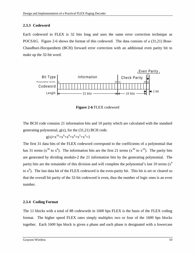
Each codeword in FLEX is 32 bits long and uses the same error correction technique as
POCSAG. Figure 2-6 shows the format of this codeword. The data consists of a (31,21) Bose-
Chaudhuri-Hocquenhem (BCH) forward error correction with an additional even parity bit to
make up the 32-bit word.
Codeword0 20
Informat ion Check Par i ty
Even Par i ty
21P o l y n o m i a l t e r m s 30
21 bits 10 bits1 bit
Bi t Type
Length
31
Figure 2-6 FLEX codeword
The BCH code contains 21 information bits and 10 parity which are calculated with the standard
generating polynomial, g(x), for the (31,21) BCH code.
g(x)=x10+x9+x8+x6+x5+x3+1
The first 31 data bits of the FLEX codeword correspond to the coefficients of a polynomial that
has 31 terms (x30 to x0). The information bits are the first 21 terms (x30 to x10). The parity bits
are generated by dividing modulo-2 the 21 information bits by the generating polynomial. The
parity bits are the remainder of this division and will complete the polynomial’s last 10 terms (x9
to x0). The last data bit of the FLEX codeword is the even-parity bit. This bit is set or cleared so
that the overall bit parity of the 32-bit codeword is even, thus the number of logic ones is an even
number.
2.3.4 Coding Format
The 11 blocks with a total of 88 codewords in 1600 bps FLEX is the basis of the FLEX coding
format. The higher speed FLEX rates simply multiplex two or four of the 1600 bps blocks
together. Each 1600 bps block is given a phase and each phase is designated with a lowercase

Design and Implementation of a Practical FLEX Paging Decoder
Grayson Wireless 11
letter (a, b, c, d). For 1600 bps FLEX, only phase a is transmitted. For 3200 bps FLEX, phase a
and phase c are transmitted and 6400 bps FLEX transmits all four phases. Each block contains
eight codewords for each phase and are multiplexed together so that the time to transmit the
block is 160 ms. For 6400 bps, each block would contain 8 codewords for phase a, 8 codewords
for phase b, 8 codewords for phase c, and 8 codewords for phase d.
The FLEX coding format is shown in Figure 2-7. The 11 blocks are shown with the order in
which information is placed. In the first codeword of the first block is the Block Information
Word which is an overhead codeword needed to identify the remaining codewords. The 2nd to
88th codewords will be the address field, vector field, message data field, and idle codewords
field. The number of codewords used in each field is based on the information transmitted. The
address field identifies one or more pagers. The vector field identifies each pager’s message type
and where the message content is located in the message field.
BlockInformat ionCodeword
88 Codewords in 11 Blocks
AddressField
VectorField
MessageData Field
IdleCodewords
Figure 2-7 FLEX coding format
The number of codewords required for the FLEX coding format for tone, 10 digit numeric, and
40 Character Alphanumeric page compared with POCSAG are shown in Table 2-1. The number
of codewords does not include the overhead codes associate with each paging standard. For each
1600 bps FLEX coding format, there is one overhead codeword per 88 codewords which is the
block information codeword. For POCSAG, there is one overhead codeword per 17 codewords
which is the synchronization word. The percent of the coding format designated for overhead
information is reduced from 5.88% for POSCAG to 1.14% for FLEX.

Design and Implementation of a Practical FLEX Paging Decoder
Grayson Wireless 12
Table 2-1 Codewords per paging type
2.4 Fading Tolerance
The robust nature of FLEX can be seen both in the synchronization period and the interleaved
data bits in each block. The protocol has been designed to tolerate fades up to 10 ms in duration
in the synchronization period and in each data block. Fading is the result of a frequency that is
temporarily received at a signal less than the median signal level. How much the signal is less
than the median level is the depth of the fade and how long the signal is less than the median is
its duration. When the frequency in the operational bandwidth of the pager fades, the received
signal level compared to noise or signal to noise ratio (SNR) decreases. The smaller the SNR,
the more likely the data will be detected incorrectly. Thus as SNR decreases, the bit error rate
(BER) increases. Fading causes the BER to be large for a short period of time. Fading tolerance
is important to paging operators because it spreads the effect of the fade over a long period of
time. By spreading the effect of the fade, the overall BER can be reduced to a level that is
correctable with the BCH code. Pagers operate in a mobile environment which is very
susceptible to fast and slow fading. [Rap 96] shows the effect of fading in urban environments.
Motorola chose the 10 ms fading tolerance so that FLEX would achieve a much better fading
tolerance than POCSAG. [Mot 94] contains the Table 2-2 which shows the reduced effect of the
fading environment of FLEX compared with POCSAG.
Paging Standard POCSAG FLEX
Tone 1 2
Numeric10 digit 3 4
Alphanumeric40 Char 15 17

Design and Implementation of a Practical FLEX Paging Decoder
Grayson Wireless 13
Table 2-2 Relative signal strength for 99% success rate of 80 characters alphanumeric message
Fading environment: Single Rayleigh fade with Doppler frequency = 6.85 Hz which is 5 mph @
900 Mhz.
The first part of the FLEX synchronization (Sync1) is set up such that a 10 ms fade, which is 16
bits at 1600 bps, will not effect both synchronization words in the same fade. The 16 bits of
dotting between the synchronization words ensures that at least one sync codeword will be
decoded. Thus a 10 ms fade can be tolerated during the 115 ms synchronization for a FLEX
pager to decode only one sync codeword and to continue processing the frame. The interleaving
of the data bit in a FLEX block allows up to 16 consecutive bits to be in error for 1600 bps,
because when the data is de-interleaved, each codeword will only contain 2 bit errors and the
BCH forward error correction will correct them. For 3200 bps, 32 consecutive bits can be in
error, and for 6400 bps, 64 consecutive bits can be in error. The data in a block are transmitted
by column and each column takes 5 ms to transmit, so two consecutive columns form 10 ms of
data. Thus a 10 ms fade can be tolerated during each of the 160 ms blocks.
2.5 FLEX and POCSAG mixed
The integration of FLEX with other asynchronous paging standards is quite simple. A FLEX
system must be setup to send a minimum number of frames per cycle. For example, the paging
operator wants FLEX pages to be sent every 30 seconds. The system software simply reserves
1.875 every 30 seconds for a FLEX frame. If multiple FLEX frames are required to send the
information then additional frames are transmitted until all the information is sent. During the
non-FLEX time other asynchronous paging data can be sent. If no FLEX paging data is available
at the 30 second interval then a frame does not have to be sent. Since FLEX is a synchronous
Paging Standard POCAG 512 POCSAG 1200 FLEX 1600 FLEX 6400
Gaussian reference -125.3 dBm -123.2 dBm -121.7 dBm -118.2 dBm
Fading Environment -102.2 dBm -95.9 dBm -107.2 dBm -104.2 dBm
Fading Degradation 23.1 dB 27.3 dB 14.4 dB 14.0 dB

Design and Implementation of a Practical FLEX Paging Decoder
Grayson Wireless 14
system it does require a frame to be sent with a minimum time so that timing between the pager
and transmitter is not lost.

Design and Implementation of a Practical FLEX Paging Decoder
Grayson Wireless 15
Chapter 3
3. Receiver and Decoder Design
3.1 Receiver
The receiver which forms the front end of the FLEX decoder is a non-coherent FSK receiver.
Figure 3-1 shows a block diagram of the receiver. The receiver is a dual-conversion
superheterodyne design and contains two local oscillators to mix down the 929-932 MHz signal
to a 455 kHz signal with a 15 kHz BW. The receiver is linear up to the test point (TP). The
signal is then detected using the Philips NE605 [Phi 96] limiter to produce an FM demodulated
output. The output of the limiter is a DC coupled discriminated audio signal. The DC coupled
audio is important to use when detecting FSK signals that have no guaranteed transition changes
per bit. AC coupling is performed with a capacitor that couples the changes in the voltage on a
reference DC voltage. AC coupling is pattern sensitive and will not decode properly with a
threshold comparator.

Design and Implementation of a Practical FLEX Paging Decoder
Grayson Wireless 16
4 POLEXTAL Fi l
FM DemodulatedDiscr imated Audio
(DC-15kHz)Test Point (TP)15 kHz BW
933 MHzCer Fil
933 MHzCer Fil
AT-42086
RMS2MIXER
2SC3356BJT
NE605MIXER
45 MHz929 MHz -932 MHz
NE605IF AMP
Ceramic455 KHz
Ceramic455 KHz
NE605Limiter
974 MHz -977 MHz
44.545 MHz
15 kHz BW
455 kHz
Figure 3-1 Receiver block diagram
The receiver’s design of mixing the signal down has the possibility of inverting the data
depending on which signal is filtered when the down conversion is performed. From the law of
cosine the product of two cosine waves are
( ) ( ) ( )[ ] ( )[ ]cos cos cos cosω α ω α ω αt t t t• = − + +1
2
1
2
When this is converted to the frequency domain, there are two impulses: one at ω + α and one at
ω - α. There are two possible ways to mix the signal down to an intermediate frequency (IF):
low side injection and high side injection. Low side injection is when the local oscillator (LO)
into the mixer is less than the input frequency. High side injection is when the LO is greater than
the input frequency. Since the receiver is only mixing down the frequency the cos[(ω - α)t] is the
only term that is used. Figure 3-2 shows how normal FM demodulation maps a frequency to a
voltage and the higher the frequency the higher the voltage. Data inversion occurs when two
frequencies are such that fbit1 is greater than fbit0 but after mixing down fbit1 is less than fbit0. Data
inversion is not a problem, it just needs to be known so that the correct symbol is decoded.

Design and Implementation of a Practical FLEX Paging Decoder
Grayson Wireless 17
For high side injection
flo-high > fbit1 > fbit0.
when mixed down
fIF-bit1 = flo-high- fbit1 fIF-bit0 = flo-high- fbit0
since fbit1 > fbit0 then
fIF-bit1 < fIF-bit0
Data inversion occurs with high side injection.
For low side injection
fbit1 > fbit0.>flo-low
when mixed down
fIF-bit1 = fbit1 - flo-low fIF-bit0 = fbit0 - flo-low-
since fbit1 > fbit0 then
fIF-bit1 > fIF-bit0
No data inversion (normal FM demodulation) occurs with low side injection.
For the given receiver, the receiver uses high side injection to mix the signal down to 45 MHz so
that data is inverted. Then the low side injection is used to mix the signal down to 455 KHz
which does not inverted the data so the overall data is still inverted. The NE605 limiter is a
quad detector that inverts the data so the overall data pattern is not inverted by the receiver. Data
inversion can be handled by inserting an inverting amplifier with unity gain after the FM
discriminator so that the data pattern is corrected.
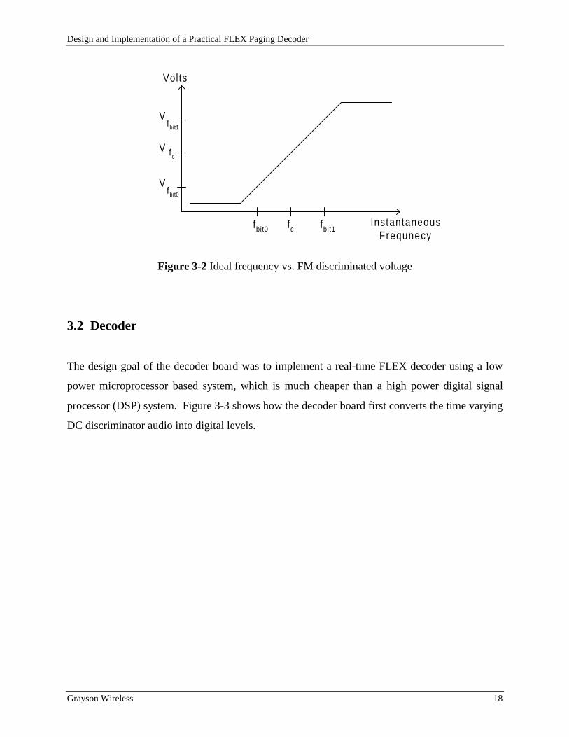
The ideal frequency vs. FM discriminated voltage for a non-inverted receiver is shown in Figure
3-2. The output voltage at the tuned or center frequencies is Vfc. A frequency greater than the
center frequency will produce an output voltage larger than the center frequency voltage.
Likewise a frequency less than the center frequency will produce an output voltage less than the
center frequency voltage.
Design and Implementation of a Practical FLEX Paging Decoder
Grayson Wireless 18
fc
fc
V
fbit0 fbit1
fbit0
V
fbit1
V
Volts
InstantaneousFrequnecy
Figure 3-2 Ideal frequency vs. FM discriminated voltage
3.2 Decoder
The design goal of the decoder board was to implement a real-time FLEX decoder using a low
power microprocessor based system, which is much cheaper than a high power digital signal
processor (DSP) system. Figure 3-3 shows how the decoder board first converts the time varying
DC discriminator audio into digital levels.

Design and Implementation of a Practical FLEX Paging Decoder
Grayson Wireless 19
Maximum orPeak+ Detector
Min imum orPeak- Detector
Sample& Hold
Sample& Hold
3-LevelCompar i tor
Max Level
Min Level
uP Control
uP Control
Low
DC CoupledAudio High
Middle
LPF
Input
Figure 3-3 Decoder discrimination
The DC Coupled Audio signal first passes through a low pass filter (LPF) to remove any high
frequency components (455 kHz) that occur due to the mixing down of the RF signal by the
receiver. The LPF is also required to improve the signal to noise ratio by reducing the bandwidth
so that the best ratio of signal power to noise bandwidth power is achieved. The exact cut-off
frequency and the order of the filter is propriety to the FLEX protocol. The filtered audio passes
to two peak detectors: Peak+ Detector and Peak- Detector. These are discrete circuits that
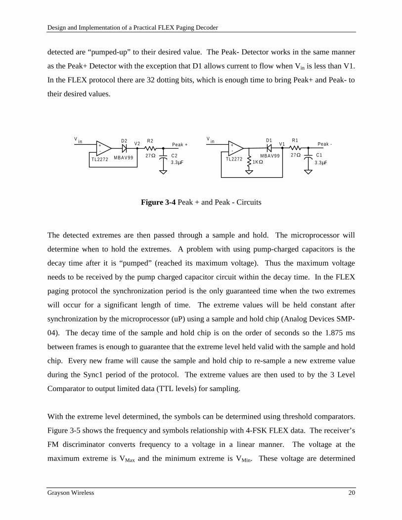
determine the two extremes of the discriminated audio. Figure 3-4 shows both Peak Detector
circuits [Gra 71] used on the decoder. For the Peak+ Detector, when the filter audio voltage (Vin)
is greater than V2, the diode D2 allows current to pass and the OP amp, TL2272, will bring its -
input (V2) equal to its + input (Vin). The capacitor C2 charges with the time constant:
t R C F s= • = • =27 33 89Ω . µ µ
For 3200 baud data, the period is 312µs so that it will take 2 dotting bits (1 high and 1 low) to
charge the capacitor of both peak detectors to be within 3 dB of the desired voltage. The term
pump-charged capacitor is used to describe this procedure, because for every bit one of the peak
Design and Implementation of a Practical FLEX Paging Decoder
Grayson Wireless 20
detected are “pumped-up” to their desired value. The Peak- Detector works in the same manner
as the Peak+ Detector with the exception that D1 allows current to flow when Vin is less than V1.
In the FLEX protocol there are 32 dotting bits, which is enough time to bring Peak+ and Peak- to
their desired values.
+-
D2 R2
C2TL2272
Peak +
27Ω
V2V in
+-
D1 R1
TL2272
Peak -
1KΩC1
3.3µF
V1V in
M B A V 9 9 M B A V 9 9 27Ω3.3µF
Figure 3-4 Peak + and Peak - Circuits
The detected extremes are then passed through a sample and hold. The microprocessor will
determine when to hold the extremes. A problem with using pump-charged capacitors is the
decay time after it is “pumped” (reached its maximum voltage). Thus the maximum voltage
needs to be received by the pump charged capacitor circuit within the decay time. In the FLEX
paging protocol the synchronization period is the only guaranteed time when the two extremes
will occur for a significant length of time. The extreme values will be held constant after
synchronization by the microprocessor (uP) using a sample and hold chip (Analog Devices SMP-
04). The decay time of the sample and hold chip is on the order of seconds so the 1.875 ms
between frames is enough to guarantee that the extreme level held valid with the sample and hold
chip. Every new frame will cause the sample and hold chip to re-sample a new extreme value
during the Sync1 period of the protocol. The extreme values are then used to by the 3 Level
Comparator to output limited data (TTL levels) for sampling.
With the extreme level determined, the symbols can be determined using threshold comparators.
Figure 3-5 shows the frequency and symbols relationship with 4-FSK FLEX data. The receiver’s
FM discriminator converts frequency to a voltage in a linear manner. The voltage at the
maximum extreme is VMax and the minimum extreme is VMin. These voltage are determined

Design and Implementation of a Practical FLEX Paging Decoder
Grayson Wireless 21
using the pump-charge capacitors and held by the sample and hold chip after Sync1 is detected.
During Sync1, the voltage from the pump-charged capacitors are used directly, because the peak
voltages are being received. A three comparator system is used to determine the two bit symbol.
The same comparators work for 2-FSK data but only the center or average threshold is needed.
The threshold voltage level for each is shown by the wider dotted line in Figure 3-5.
+4.8 kHz
-4.8 kHz
FrequencyDeviat ion Bit Pattern
-1.6 kHz
Symbol Values
+1.6 kHz
00 10 0111
+3.2 kHz
-3.2 kHz
V Max
V T-High
V T-Avg
V T-Low
V Min
Vol tageLevels
0 kHz
Figure 3-5 Frequency deviation, threshold voltage level, and 4-FSK symbolrelationship
Since the difference between two adjacent levels is 3.2 kHz, the threshold voltage is set to half
way between two adjacent levels. The first comparator that needs to be examined is the center
comparator whose threshold voltage is
VV V
T AvgMax Min
− = +2
where VT-Avg is the average or center comparator voltage level.
Only one of the other two comparators needs to be examined after the value of the center
comparator is known. The threshold voltage for the high side comparator (used when center
comparator outputs a logic 1) is

Design and Implementation of a Practical FLEX Paging Decoder
Grayson Wireless 22
( )V
V VVT High
Max T Avg
T Avg−−
−=−
+2
3
which reduces down to
VV V
T HighMax Min
− = +5
6
The threshold voltage for the low side comparator (used when center comparator outputs a logic
0) is
VV V
VT LowT Avg Min
Min−−=
−+
3
which reduces down to
VV V
T LowMin Max
− = +5
6
The comparator threshold levels are dependent on the values of VMin and VMax. Figure 3-6 shows
how these levels were determined using a resistor divider. For VT-Avg, the values of the resistors
must be
R R R R1 2 3 4+ = +
so that the voltage drop from VT-Max to VT-Avg and VT-Avg to VT-Min are the same. For both VT-Min
and VT-Max the voltage drop ratio from R1 to R2 and R4 to R3 must 1/3. Using the resistor
divider rule,
R
R R
1
1 2
1
3+=
which reduces to
R R2 2 1= •
Similarly for R3 and R4,
R R3 2 4= •
The author chose a value of R1 which would be much greater than the 27Ω resister in the pump-
charge so that its resistance can be ignored. Thus a value of 2.49 KΩ was chosen for R1 which is
about 100 times 27Ω. This led R2 to be determined as 4.87 KΩ(closest resistor to 4.98 KΩ).
The symmetry around VT-Avg meant that R4=R1 and R3=R2.

Design and Implementation of a Practical FLEX Paging Decoder
Grayson Wireless 23
R2
V T-Avg
R3R4
R1
V T-Low
V T-High
V Max
V Min
2.49 KΩ 4.87 KΩ
4.87 KΩ2.49 KΩ
+-
+-
+-
V In
V In
V In Low
Middle
High
LM339
LM339
LM339
Figure 3-6 Resistor divider used to detect threshold voltage levels
Figure 3-6 also shows how these levels are used at negative inputs into a comparator (LM339).
If the input voltage (Vin) is less than the threshold then the output of the LM339 is a TTL low,
otherwise the output is TTL high. The limited data (High, Middle, and Low) is then
simultaneous clocked into three shift registers. The sampled data can then be directly read by the
microprocessor. Figure 3-7 shows a block diagram of how this occurs. The microprocessor can
control the sample rate. The approach taken with this design was to sample at 8 times the baud
rate. Thus the sample clock will be running at 12800 Hz for 1600 baud or 25600 Hz for 3200
baud.
Figure 3-7 Limited Data into Microprocessor
The microprocessor must perform symbol determination and symbol clock synchronization in
order to accurately recover the data.
Low
Middle
High8-Bit ShiftRegister
8-Bit ShiftRegister
8-Bit ShiftRegister
Clock
8
8
8uP

Design and Implementation of a Practical FLEX Paging Decoder
Grayson Wireless 24
The symbol determination was performed by first determining the most significant bit (MSB).
Bit determination is the majority bit in the shift register or metric of data. This was implemented
with a look up table for speed. Because of timing jitter, which is corrected for by the
synchronization, and symbol transition time, not all 8 samples are used to determine the bit. For
the MSB, the middle 6 samples were used to determine the bit and only the middle 4 samples
were used to determine the least significant bit (LSB). The MSB is determined from the middle
sample shift register. Once the MSB is determined, the LSB is determined from the either the
low sample shift register or high sample shift register based on the MSB. If the MSB is a logic 1,
then LSB is determined from the high sample shift register. The Gray coding requires that result
of this LSB be inverted so that symbol associated with the highest deviation be 10. If the MSB is
a logic 0, then LSB is determined from the low sample shift register. The Gray coding
requirement is correct with this LSB since the symbol associated with the lowest deviation will
be 00.
Symbol determination is using the sampled data to determine one of the four possible symbols
for 4-FSK or one of two possible symbols for 2-FSK. The ideal symbol determination would be
to integrate over the entire symbol and the result would map into one of the possible symbols.
This approach is very similar but a few variations. First the data from the discriminator are
limited to a logic 1 or 0 thus there is no resolution of how close each sample is to the threshold
voltage. Also the data is only sampled 8 times in a symbol period. An ideal integrator would
have an infinite number of samples. Also all 8 samples might not be in the same symbol period
due to clock variations. Adjustment of the sample clock is performed with the symbol clock
synchronization algorithm.
The symbol timing is determined with each MSB. The 8 samples in the middle shift register are
examine to see where the bit energy is centered. If the bit energy is centered around the middle,
which is bits 3 or 4, then the next sample will be taken in 8 clocks. If the bit energy is centered
toward the more recent samples, which is bits 0, 1, or 2, the next sample will be taken in 9
clocks. This is a lag condition in which the sample clock is delayed so that the next bit will be
Design and Implementation of a Practical FLEX Paging Decoder
Grayson Wireless 25
centered. If the bit energy is centered toward the older samples which is bits 5, 6 or 7, the next
sample is taken in 7 clocks. This is lead condition in which the sample clock is increased so that
the next bit will be centered. Just as the bit determination is implemented with a look up table
for speed, so is the symbol timing.
The sample clock used in this design is divided down by a crystal that is rated at ±100 ppm so
this means the sample clock can be off by ±0.01 %. For the data to slip 1/8 of a symbol time it
would take 1/8 divided by 0.01% or 1250 bits minimum before a symbol timing needs to be
adjusted.
3.3 Microprocessor software implementation
The microprocessor used in this design was a Dallas 80C320 which is a fast 80C31/80C32-
compatiable microcontroller [Dal 93]. The DS80C320 uses the 8051 instruction set with an
average speed improvement of 2.5 time faster. The microprocessor software was implemented
using some of the inherent features of microprocessor. The microprocessor had two processes
running at the same time: interrupt processing and main processing. The interrupt processing
was used for the time critical process of symbol determination and collection and maintaining
symbol timing. The main processing was used to examine the collected data for the FLEX
protocol and report the formatted data.
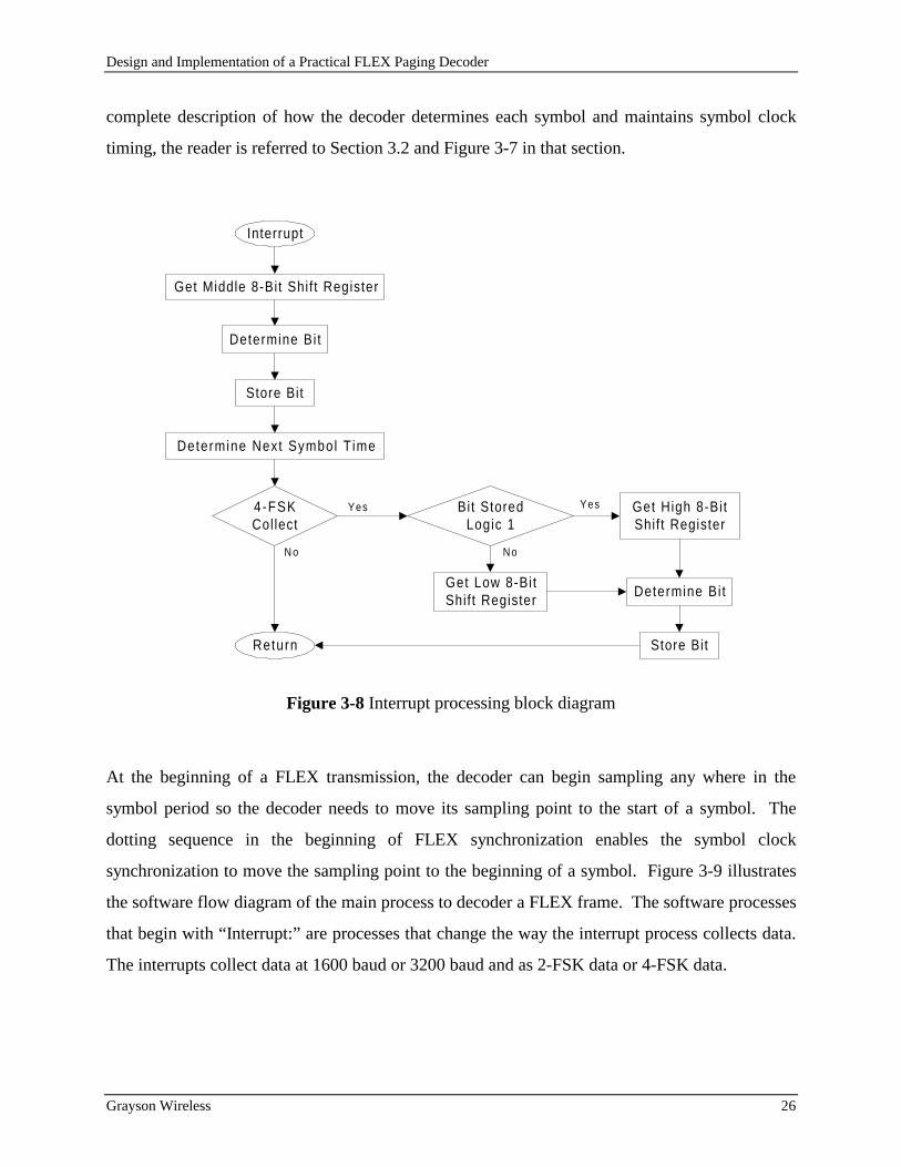
The previous section described how the microprocessor determined the symbol and maintained
clock synchronization. This is what is occurring during the interrupt processing. Figure 3-8 is
the block diagram for the interrupt processing. The processes Determine Bit and Determine Next
Symbol Time in Figure 3-8 are implemented using a table look-up of the 8-bit sampled value.
This allows fast determination of bit and next timing value. The symbol timing is loaded into a
counter that decrements with each sample clock. When the count goes to zero, the interrupt
occurs. The main processing loop is temporarily suspended while the interrupt is processed.
Figure 3-8 is only provided to illustrate how the software process is implemented. For a
Design and Implementation of a Practical FLEX Paging Decoder
Grayson Wireless 26
complete description of how the decoder determines each symbol and maintains symbol clock
timing, the reader is referred to Section 3.2 and Figure 3-7 in that section.
Interrupt
Get Middle 8-Bit Shif t Register
Determine Bi t
Store Bit
Determine Next Symbol T ime
4-FSKCollect
No
Get Low 8-BitShif t Register
Bit StoredLogic 1
No
Yes Yes
Return
Get High 8-BitShif t Register
Determine Bi t
Store Bit
Figure 3-8 Interrupt processing block diagram
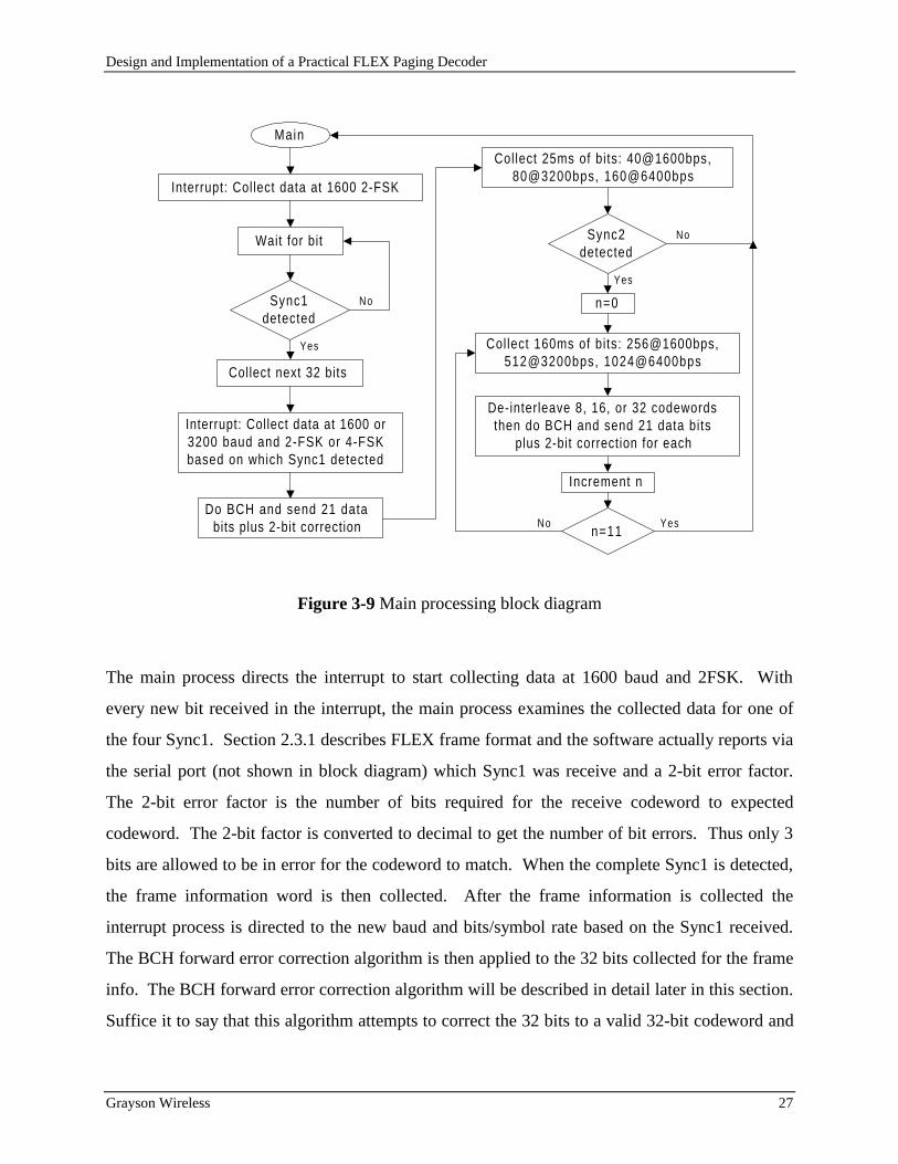
At the beginning of a FLEX transmission, the decoder can begin sampling any where in the
symbol period so the decoder needs to move its sampling point to the start of a symbol. The
dotting sequence in the beginning of FLEX synchronization enables the symbol clock
synchronization to move the sampling point to the beginning of a symbol. Figure 3-9 illustrates
the software flow diagram of the main process to decoder a FLEX frame. The software processes
that begin with “Interrupt:” are processes that change the way the interrupt process collects data.
The interrupts collect data at 1600 baud or 3200 baud and as 2-FSK data or 4-FSK data.
Design and Implementation of a Practical FLEX Paging Decoder
Grayson Wireless 27
Main
Interrupt: Collect data at 1600 2-FSK
Wait for bit
Collect next 32 bits
Sync1detected
No
No
Yes
Yes
n=0
Collect 160ms of bits: 256@1600bps,512@3200bps, 1024@6400bps
Interrupt: Collect data at 1600 or3200 baud and 2-FSK or 4-FSKbased on which Sync1 detected
Do BCH and send 21 databits plus 2-bit correction
Collect 25ms of bits: 40@1600bps,80@3200bps, 160@6400bps
Sync2detected
De-interleave 8, 16, or 32 codewordsthen do BCH and send 21 data bits
plus 2-bit correction for each
n=11
Increment n
No Yes
Figure 3-9 Main processing block diagram
The main process directs the interrupt to start collecting data at 1600 baud and 2FSK. With
every new bit received in the interrupt, the main process examines the collected data for one of
the four Sync1. Section 2.3.1 describes FLEX frame format and the software actually reports via
the serial port (not shown in block diagram) which Sync1 was receive and a 2-bit error factor.
The 2-bit error factor is the number of bits required for the receive codeword to expected
codeword. The 2-bit factor is converted to decimal to get the number of bit errors. Thus only 3
bits are allowed to be in error for the codeword to match. When the complete Sync1 is detected,
the frame information word is then collected. After the frame information is collected the
interrupt process is directed to the new baud and bits/symbol rate based on the Sync1 received.
The BCH forward error correction algorithm is then applied to the 32 bits collected for the frame
info. The BCH forward error correction algorithm will be described in detail later in this section.
Suffice it to say that this algorithm attempts to correct the 32 bits to a valid 32-bit codeword and

Design and Implementation of a Practical FLEX Paging Decoder
Grayson Wireless 28
returns a 2-bit error correction factor. The software then sends the 21 data bits (see Section 2.3.3
for codeword structure) and the 2-bit error correction factor via the serial port. The 2-bit error
correction factor is similar to the one described in the reporting of the Sync1 detected.
All data that is now collected is with new baud rate of 1600 or 3200 and the bits/symbol is either
1 (2-FSK) or 2 (4-FSK). Sync2 is collected first and compared to the expected Sync2. If Sync2
is not within 3 bits of expected then the software reports an error with Sync2, otherwise a good
Sync2 is reported with a 2-bit error factor (not shown in block diagram). The 11 blocks of
interleave are now collected. The block number is shown as “n” in the block diagram. The 160
ms of data are collected. The data is de-interleaved by simply reversing the interleave process
described in section 2.3.2. The number of codewords that will be de-interleaved is 8, 16, or 32
based on the respective data rate 1600, 3200, or 6400 bps. For each codeword, the BCH forward
error correction algorithm is employed on the codeword. The software then sends the 21 data
bits, the block number, word number interleaved, and the 2-bit error correction factor via the
serial port.
The standard BCH decode algorithm as defined in [Lin 83] involves three steps. Compute the
syndrome, S, from the received data, determine the error-location polynomial, σ(z), from the
syndromes, and then determine the error-location numbers by finding the roots of the error-
location polynomial. There are two syndromes that need to be calculated with the (31,21) BCH:
S1 and S3. Both are calculated by dividing the received pattern by the minimum polynomials
M1 and M3.
M1 = X5+X2+1
M3 = X5+X4+X3+X2+1
The routine used to calculate this division is quite simple in an 8-bit micro-processor. It requires
two working division registers: m1 and m3. Each received bit is shifted into the LSB of the
working m1 register. If the bit in the 5th bit location of m1 is a logic one then m1 is exclusive
ORed (XORed) with the value 0x25, otherwise m1 is not changed. The same process is
performed with the working m3 but the value XORed is 0x3D. This accomplishes in software

Design and Implementation of a Practical FLEX Paging Decoder
Grayson Wireless 29
what would be implemented in hardware with taps at each location. After all 31 bits pass
through these two shifting registers, the resulting m1 and m3 are used to calculate S1 and S3.
Syndrome 1 is simply the result in m1 (S1=m1). The calculation for Syndrome 3 which uses m3
is given below. The notation of S3.0 means Syndrome 3 bit location 0. All addition with m3 bit
location is modulo 2.
S3.0 = m3.0
S3.1 = m3.2+ m3.3+ m3.4
S3.2 = m3.4
S3.3 = m3.1+ m3.2+ m3.3+ m3.4
S3.4 = m3.3
The error-location polynomial, σ(z) will be one of the following based on S1 and S3 [Mac 77].
i) If S1=S3=0, σ(z) = 0. (No errors)
ii) If S1 != 0, S3 = S13, σ(z) = 1+S1z. (1 bit error)
iii) If S1 != 0, S3 != S13, σ(z) = 1 + S1z + ((S3/S1 + S12)z2. (2 bit errors)
A table look up of the Galois Field (GF) for the minimum polynomial m1(x) is given in [Lin 83].
An inverse table to the GF is also used so that multiplication of values can be done using the GF
index or power so that addition can be used. The error-location polynomial is evaluated for each
bit σ(αi) and if the result is zero then that bit is in error. The overall even parity bit was also used
to help determine the number of bits in error. An incorrect received even parity means that there
are an odd number of bits in error, and a correct received even parity means there is an even
number of bits in error. The parity bit itself might be a bit in error and it is not included in the
BCH error encoding.
3.4 BER Measurements
The number of bits required for a valid BER measurement is determined by the method
“bounded binomial sampling” which is used as one of the method in [Fun 91]. Bounded
Design and Implementation of a Practical FLEX Paging Decoder
Grayson Wireless 30
binomial sampling provides a boundary on how many bits must be collected for an accurate BER
measurement. Accuracy is given in terms of certain relative precision and a certain absolute
precision. [Cro 76] describes this method and give figures for the minimum number of bit errors
required for relative precision and minimum number of bits for an absolute precision. The test
procedure did not allow for an exact adherence to the stop condition as described in [Cro 76] and
used by [Fun 91]. Instead the test time was the major factor, so the total number of bits measured
was based on this restriction. The research was more interested in the performance at high BER
than at low BER. Absolute precision is the deciding factor with high BER measurements. The
goal was to measure a minimum number of bits so as to have a relative precision of 1 bit in a
FLEX 6400 bps frame. Since there are 352 codewords in a 6400 bps frame the BER would be
8.9e-5. From Figure 2 in [Cro 76] that requires 3e+8 bits to measure. Test time prevented this
from being achieved. Instead 1.7e+8 bits were measured. Given this as the minimum number of
bits the absolute precision would be about 1.2e-4 which is 1.4 bits in a 6400 bps frame.
A known randomly generated pattern, FLEX encoded, will be transmitted at a known power
level. This power level will be decreased so that an Eb/No plot can be generated for uniform
comparison. The energy per bit, Eb, is the signal power divide by number of bits per second.
Only 6400 bps FLEX is being measured, so Eb is received power divided by 6400. The noise
spectral density, No, is the noise power divided by equivalent noise bandwidth. Chapter 4 gives a
more detailed description of the noise power and equivalent noise bandwidth. If the received
codeword is correct (compared to the known randomly generated one) then the 2-bit error
correction bits will be used to determine the number of bits in error, and the total usable bits is
incremented by 32. If the codeword is not corrected then it is counted as a codeword erasure. In
either case a total codeword count is incremented. If the frame is missed then it is a frame
erasure. There are two frame erasures, one due to sync1 not being detected (An) and another due
to sync2 not being detected (Comma). In either case of a frame received or missed the total
frame count is incremented. The following are how the BER is calculated taking into account the
various erasures.

Design and Implementation of a Practical FLEX Paging Decoder
Grayson Wireless 31
BER bits = bits in error / total usable bits
BER CW = codeword erasures / total codewords
BER Frame = (An erasures + Comma erasures) / total frames
Block BER =(bits in error + (32 * codeword erasures)) / (total codewords * 32)
System BER = (bits in error + (32 * codeword erasures) + ((An erasures + Comma
erasures)* 11264) ) / (total frames * 11264)
The following is how Eb/No is computed
Eb/No (dB) = 10*Log(((Tx Power - cable loss)(mW)/6400) / No(mW))
The BER versus Eb/No results for each receiver that will be compared are BER bits, BER system,
and BER 4FSK. BER bits and BER system are measured and BER 4FSK is the ideal BER for 4-
level FSK non-coherent detection taken from [Lat 89].

Design and Implementation of a Practical FLEX Paging Decoder
Grayson Wireless 32
Chapter 4
4. Measurements
All measurements were performed on three receiver/decoder pairs. The Grayson serial number
for the three receivers were AS4928, AS4927, and AS2387. All measurements were performed
with the receiver tuned to 930 MHz which is near the center of the paging spectrum. Thus all
signal generators were tuned to 930 MHz for these measurements. Due to time limitations, only
two of the three receivers measured have BER measurements and plots.
4.1 Linear Receiver
Figure 4-1 illustrates the measurement setup for confirming that the receiver is linear up to TP
for small signals. The HP8657A signal generator had its output power stepped from -125 dBm
up to -80 dBm in 5 dB steps. At each level, the peak power measured by the spectrum analyzer
is recorded. The actual dBm measurement taken at each RF level is not important, just the
difference between levels.

Design and Implementation of a Practical FLEX Paging Decoder
Grayson Wireless 33
Figure 4-1 Linearity measurement
The HP8591A spectrum analyzer was setup with the values shown in Table 4-1. The test point
(TP in Figure 3-1) is where the received signal has been mixed down to 455 KHz. The filter
bandwidth was 15 KHz so the span was set to 50 KHz to ensure the entire signal is received.
The resolution bandwidth of 1 KHz was chosen as an adequate bandwidth so that the signal can
be displayed but not too fine that the sweep time would not be very long. The video averaging
was enabled so that variations in signal power due to noise at small input signal levels (-125
dBm) would be averaged out. 50 samples required only 15 seconds to acquire. The Tektronics
P6201 FET probe is a 50Ω impedance probe that can be used over a wide frequency range that
includes 455KHz. Measuring only differences does not require the probe to be match.
R FInput
HP8657ASig Gen
HP8591ASpec Anyzr
TEK-P6201FET PROBE
GraysonReceiver
R FInput
T P

Design and Implementation of a Practical FLEX Paging Decoder
Grayson Wireless 34
Table 4-1 HP8591A spectrum analyzer setup
4.2 Equivalent noise bandwidth
The equivalent noise bandwidth of a receiver is defined as the width of a fictitious rectangular
spectrum such that the power in that rectangular band is equal to the actual spectrum over
positive frequencies [Cou 90]. The height of the fictitious rectangular spectrum is the maximum
value in the actual spectrum [Bli 76]. Figure 4-2 illustrates the measurement for making the
actual spectrum of the receiver. The receiver is connected to a 50Ω load and the spectrum
analyzer sweeps the actual noise spectrum over the negative (less than 455 KHz) and positive
frequencies. The HP8591A spectrum analyzer had the same setup as shown in Table 4-1. The
HP-IB interface of the HP8591A to a PC allows the actual video spectrum to be saved in a text
format so that a computer program can be used to determine the equivalent noise bandwidth (see
Appendix for program listing). The software used to interface with HP8591A was HP VEE
which is a Microsoft Windows based program that allows quick control and access to various
instruments. The details of HP VEE software will not be discussed because any program written
to interface with HP-IB could have been used to obtain the spectrum data, and the fact that HP
VEE is a very user friendly software package [Hp 93].
Setting Value
Center Frequency 455 KHz
Span Frequency 50 KHz
Resolution Bandwidth 1KHz
Sweep Time Auto (300 msec)
Video Average On with 50 Averages
Video BW/Resolution BW 1.0
Y Display Log (dB)
X Display Linear (Hz)

Design and Implementation of a Practical FLEX Paging Decoder
Grayson Wireless 35
R FInput
50 OhmLoad
HP8591ASpec Anyzr
TEK-P6201FET PROBE
GraysonReceiver
R FInput
T PPC running
HP VEE
HP- IB
Figure 4-2 Equivalent noise bandwidth measurement
4.3 Noise power
The noise power is measured using some basic principles of signal powers and linear
receivers. If two signals are independent, the combined power of each signal is simply the sum
in dB of those two independent signals. For linear receivers, the sum of two equal signal powers
will be 3 dB less than the power of one signal. Figure 4-1, which is the linearity measurement
setup, is also the same measurement setup for measuring noise power. The HP8591A has the
same setup as shown in Table 4-1 except that the resolution bandwidth is set to 30KHz. The
increased bandwidth allows for smoother measurements that include the entire bandwidth (15
KHz bandpass filters). The power at the test point (TP in Figure 3-1) is measured with the RF
out of the signal generator off (50Ω load) connected to the RF input of the receiver. The RF out
of signal generator is enabled at -130 dBm. The signal level is increased until the power at TP is
3 dB greater than what the level was when the signal generator was off. This was easily done by
using the delta marker function in the HP8591A. From mathematics, the doubling of a number is
3dB (actual 10*log(2) = 3.0103 dB). From [Col 85], the sum of two independent signal powers
is simply the sum in dB of each power. The signal generator power and the noise power are
independent signals. By increasing the signal generator so that the measured power at TP is 3 dB
greater, the two signals are then at equal power. The noise power is the RF input power into the
receiver which is the signal generator level minus the cable loss.

Design and Implementation of a Practical FLEX Paging Decoder
Grayson Wireless 36
4.4 Cable loss
The cable loss measurement is shown in Figure 4-3. The HP8657 signal generator was set at
level of +15 dBm. The HP8920A was set to duplex test. The tune frequency was set to
automatic. With the desired cable not connected but the HP8657 and HP8920A connected, the
reference level of the TX power on the HP8920A is set to zero. TX power on the HP8920A is
the measurement of the received power. The desired cable is inserted and the cable loss is the
TX power. The HP8920A is very accurate at measuring levels around +15 dBm. The cable loss
measurement was performed on the cable from the HP8656A in the noise power measurement
and in the cables and splitter in the FLEX data measurement (next section) from the HP8648A to
each receiver.
RFOutput HP8920A
HP8657ASig Gen
RFInput
After zero referenceinsert desired cable
Figure 4-3 Cable loss measurement
4.5 FLEX data
The FLEX data measurement is shown in Figure 4-4. The HP8648A signal generator includes a
FLEX encoder option. This option allows the frame info codeword and all block codewords to
be download as arbitrary codewords for up to 128 frames or 1 cycle. The author wrote a PC
program that would randomly generate the codewords for all 128 frames and download them to
the HP8648A over a HP-IB interface. The Frame Info was kept unique so that the frame number

Design and Implementation of a Practical FLEX Paging Decoder
Grayson Wireless 37
could be extracted out. The program saved the random data to a file for later processing (file
number and flex rate given). The program would also adjust the output power level of the
generator and start the flex encoder. The program would also stop the encoding. The listing of
this program is in the Appendix. Each function that the program performed was based on its
command line arguments.
Figure 4-4 FLEX data measurement
The PAGETRACKER Pro software, owned by Grayson Wireless, was mostly coded by the
author. The code was modified to incorporate a raw FLEX data frame collected using the HP-IB
program that interfaces to the HP8648A. Figure 4-5 shows the block diagram of how the test
was performed. All HP8648A accesses were performed by calling the previously discussed HP-
IB program with the appropriate arguments. The filename that the random data is saved to is
FLX4nnnn.RND, where nnnn is the unique file number assigned to each random FLEX cycle.
The file format for this file is shown in Table 4-2. The unsigned long int is the actual 32-bit
codeword downloaded to the HP8648A.
Table 4-2 Format of FLX4nnnn.RND files
HP8648ASig Gen
R FOutput
Ant 1PC running
P A G E T R A C K E RPro
HP- IB
Ant 2
Ant 3
Ant 4
4 to 1Splitter
GraysonWire less
MeasurementSystem
SerialPort
C variable type name byte size
unsigned long int frameInfo 4
unsigned long int blockData[352] 1408

Design and Implementation of a Practical FLEX Paging Decoder
Grayson Wireless 38
Start
Init ial ize HP8648AFile Num = 0
Generate Random FlexCycle data for HP8648A
dbm = - 90
Start encoding HP8648A at dbm level
Collect FLEX frames 0 to 127.Save to f i le with File Num and dbm
Stop encoding HP8648A.Decrement dbm
dBm < -126No
Increment Fi le Num
File Num <MaxFi leNum
No
Yes
Yes
Stop
Figure 4-5 FLEX data measurement block diagram
For each frame decoded, the software sends four types of information in the following order:
Sync1 detected with error bit indication, Frame info codeword, Sync2 detected with error bit
indication, and 88, 178, or 352 codewords. For this test only 6400 4-FSK FLEX data was tested
so there are 352 codewords. All codewords from the decoder include only the 21 data bits and a
two bit error indication. The codeword and error bits were packed together in a 32-bit value
(long integer) such that the 21 data bits were in bits 20 through 0 and the error bits were in bits
22 and 21. The filename that received FLEX data is RrF4nnnn.aaa where r is the receiver
number, nnnn is the unique random sequence download to HP8648A, and aaa is the amplitude
without the negative sign used by HP8648A when FLEX cycle was sent. Table 4-3 shows the
file format for each FLEX frame. The file will contain up to 128 frames. Frames can be missed

Design and Implementation of a Practical FLEX Paging Decoder
Grayson Wireless 39
due to not decoding Sync1 and thus not receiving Sync1. The rate is always 4 for 6400-4FSK.
The An_Errs is the error bits for both synchronization words in Sync1. The frameInfo is the
received 21-data bits in the frame information codeword plus the 2-bit error indication. The
C_Errs is the error bits for both synchronization words in Sync2. The blockData is the received
21-data bits in each block codeword plus the 2-bit error indication. The result is a byte value to
indicate which data was received.
Table 4-3 Format of each frame in RrF4nnnn.aaa files
An analyzing program was written to compare the known random pattern and each decoded
pattern at each signal level to produce a resultant file of bit error rates. The source code for the
analyzer code is in the Appendix.
C variable type name byte size
unsigned char rate 1
unsigned char An_Errs[2] 2
unsigned long int frameInfo 4
unsigned char C_Errs[2] 2
unsigned long int blockData[352] 1408
unsigned char result 1

Design and Implementation of a Practical FLEX Paging Decoder
Grayson Wireless 40
5. Results
5.1 Linear measurement
Table 5-1 Linear measurement
The table shows that all three receivers are linear between -90 dBm and -125 dBm input power.
A 5 dB change at the input results in a 5 dB change at the measured test point. Thus the receiver
is measured and shown to be linear over the tested range.
5.2 Cable loss measurement
Single cable used in noise power measurements is -1.15 dB.
level (dBm) AS4927 (dBm) AS4928 (dBm) AS2387 (dBm)
-125 -54.50 -53.51 -49.75
-120 -48.94 -48.52 -44.95
-115 -43.84 -43.47 -40.27
-110 -38.40 -38.05 -34.78
-105 -33.46 -33.16 -29.75
-100 -28.39 -28.07 -24.70
-95 -23.50 -23.19 -19.91
-90 -18.53 -18.20 -15.10
-85 -15.12 -14.32 -11.63
-80 -12.04 -11.45 -9.45

Design and Implementation of a Practical FLEX Paging Decoder
Grayson Wireless 41
Table 5-2 Cable loss measurement of 1 to 4 splitter and cables
5.3 Noise measurements
Table 5-3 Noise measurement
The noise power measurement has the effect of the cable loss factored out. The actual spectrum
graph printouts are available for equivalent noise bandwidth, but the author felt that the
calculations are more important. No is Noise Spectral Density.
Receiver 1 AS4927 Receiver 2 AS4928 Receiver 3 AS2387 Receiver 4 Not Used
-7.61 dB -7.52 dB -6.73 dB -7.44 dB
Receiver Noise Power Noise Power Noise BW No(mW/Hz)
AS4927 -129.35 dBm 1.16e-13 mW 10279 Hz 1.13e-17
AS4928 -129.25 dBm 1.19e-13 mW 10085 Hz 1.18e-17
AS2387 -129.55 dBm 1.11e-13 mW 10801 Hz 1.03e-17

Design and Implementation of a Practical FLEX Paging Decoder
Grayson Wireless 42
5.4 FLEX Data Measurements
Table 5-4 AS4927 FLEX measurement
Tx Usable bits Codewords (CW) Frame Erasures BER BER BER BER BERPower Tot. Bits Errored Total CWs Erasures Total An Comma bits CWs frame block system-100 1.74e+8 0.00e+0 5.45e+6 0.00e+0 15488 0 0 0.00e+0 0.00e+0 0.00e+0 0.00e+0 0.00e+0-101 1.74e+8 1.00e+0 5.45e+6 0.00e+0 15488 0 0 5.73e-9 0.00e+0 0.00e+0 5.73e-9 5.73e-9-102 1.74e+8 1.00e+0 5.45e+6 0.00e+0 15488 0 0 5.73e-9 0.00e+0 0.00e+0 5.73e-9 5.73e-9-103 1.74e+8 6.00e+0 5.45e+6 0.00e+0 15488 0 0 3.44e-8 0.00e+0 0.00e+0 3.44e-8 3.44e-8-104 1.74e+8 4.00e+0 5.45e+6 0.00e+0 15488 0 0 2.29e-8 0.00e+0 0.00e+0 2.29e-8 2.29e-8-105 1.74e+8 1.00e+1 5.45e+6 0.00e+0 15488 0 0 5.73e-8 0.00e+0 0.00e+0 5.73e-8 5.73e-8-106 1.74e+8 6.90e+1 5.45e+6 0.00e+0 15488 0 0 3.96e-7 0.00e+0 0.00e+0 3.96e-7 3.96e-7-107 1.74e+8 4.66e+2 5.45e+6 4.53e+2 15488 0 0 2.67e-6 8.31e-5 0.00e+0 8.58e-5 8.58e-5-108 1.74e+8 3.15e+3 5.45e+6 2.20e+3 15488 0 0 1.81e-5 4.04e-4 0.00e+0 4.22e-4 4.22e-4-109 1.74e+8 2.06e+4 5.45e+6 1.08e+4 15488 0 0 1.18e-4 1.98e-3 0.00e+0 2.09e-3 2.09e-3-110 1.73e+8 1.03e+5 5.45e+6 4.06e+4 15488 0 0 5.97e-4 7.46e-3 0.00e+0 8.05e-3 8.05e-3-111 1.69e+8 3.85e+5 5.45e+6 1.63e+5 15488 1 4 2.27e-3 2.98e-2 3.23e-4 3.21e-2 3.24e-2-112 1.54e+8 1.04e+6 5.44e+6 6.22e+5 15488 2 24 6.77e-3 1.14e-1 1.68e-3 1.20e-1 1.22e-1-113 1.12e+8 1.64e+6 5.38e+6 1.88e+6 15488 11 190 1.47e-2 3.50e-1 1.30e-2 3.59e-1 3.67e-1-114 4.71e+7 1.12e+6 5.06e+6 3.59e+6 15488 188 915 2.37e-2 7.09e-1 7.12e-2 7.16e-1 7.36e-1-115 1.00e+7 3.32e+5 4.22e+6 3.91e+6 15488 425 3074 3.32e-2 9.26e-1 2.26e-1 9.28e-1 9.45e-1-116 1.72e+6 7.53e+4 2.99e+6 2.94e+6 15488 776 6221 4.38e-2 9.82e-1 4.52e-1 9.83e-1 9.91e-1-117 1.64e+5 9.32e+3 1.72e+6 1.72e+6 15488 809 9792 5.67e-2 9.97e-1 6.84e-1 9.97e-1 9.99e-1-118 8.45e+3 5.76e+2 7.05e+5 7.05e+5 15488 1857 11627 6.82e-2 1.00e+0 8.71e-1 1.00e+0 1.00e+0-119 1.92e+2 1.60e+1 1.78e+5 1.78e+5 15488 6385 8598 8.33e-2 1.00e+0 9.67e-1 1.00e+0 1.00e+0-120 0.00e+0 0.00e+0 1.97e+4 1.97e+4 15488 12368 3064 1.00e+0 1.00e+0 9.96e-1 1.00e+0 1.00e+0
Table 5-5 AS4928 FLEX measurement
Tx Usable bits Codewords (CW) Frame Erasures BER BER BER BER BERPower Tot. Bits Errored Total CWs Erasures Total An Comma bits CWs frame block system-100 1.74e+8 2.50e+1 5.45e+6 0.00e+0 15488 0 0 1.43e-7 0.00e+0 0.00e+0 1.43e-7 1.43e-7-101 1.74e+8 2.50e+1 5.45e+6 0.00e+0 15488 0 0 1.43e-7 0.00e+0 0.00e+0 1.43e-7 1.43e-7-102 1.74e+8 3.40e+1 5.45e+6 0.00e+0 15488 0 0 1.95e-7 0.00e+0 0.00e+0 1.95e-7 1.95e-7-103 1.74e+8 3.90e+1 5.45e+6 0.00e+0 15488 0 0 2.24e-7 0.00e+0 0.00e+0 2.24e-7 2.24e-7-104 1.74e+8 4.20e+1 5.45e+6 0.00e+0 15488 0 0 2.41e-7 0.00e+0 0.00e+0 2.41e-7 2.41e-7-105 1.74e+8 8.40e+1 5.45e+6 0.00e+0 15488 0 0 4.81e-7 0.00e+0 0.00e+0 4.81e-7 4.81e-7-106 1.74e+8 1.07e+2 5.45e+6 0.00e+0 15488 0 0 6.13e-7 0.00e+0 0.00e+0 6.13e-7 6.13e-7-107 1.74e+8 3.41e+2 5.45e+6 0.00e+0 15488 0 0 1.95e-6 0.00e+0 0.00e+0 1.95e-6 1.95e-6-108 1.74e+8 2.29e+3 5.45e+6 0.00e+0 15488 0 0 1.31e-5 0.00e+0 0.00e+0 1.31e-5 1.31e-5-109 1.74e+8 1.62e+4 5.45e+6 2.29e+2 15488 0 0 9.26e-5 4.20e-5 0.00e+0 1.35e-4 1.35e-4-110 1.74e+8 8.63e+4 5.45e+6 1.45e+3 15488 0 0 4.95e-4 2.67e-4 0.00e+0 7.62e-4 7.62e-4-111 1.74e+8 3.41e+5 5.45e+6 9.47e+3 15488 0 2 1.96e-3 1.74e-3 1.29e-4 3.69e-3 3.82e-3-112 1.71e+8 9.92e+5 5.45e+6 9.22e+4 15488 1 9 5.79e-3 1.69e-2 6.46e-4 2.26e-2 2.32e-2-113 1.56e+8 1.93e+6 5.42e+6 5.51e+5 15488 6 96 1.24e-2 1.02e-1 6.59e-3 1.13e-1 1.19e-1-114 1.02e+8 1.99e+6 5.20e+6 2.01e+6 15488 134 573 1.95e-2 3.86e-1 4.56e-2 3.98e-1 4.25e-1-115 3.15e+7 8.29e+5 4.61e+6 3.62e+6 15488 196 2199 2.63e-2 7.86e-1 1.55e-1 7.92e-1 8.24e-1-116 5.26e+6 1.91e+5 3.47e+6 3.31e+6 15488 585 5033 3.62e-2 9.53e-1 3.63e-1 9.54e-1 9.71e-1-117 6.24e+5 3.09e+4 2.08e+6 2.06e+6 15488 1340 8233 4.94e-2 9.91e-1 6.18e-1 9.91e-1 9.97e-1-118 3.84e+4 2.29e+3 8.99e+5 8.97e+5 15488 3330 9605 5.96e-2 9.99e-1 8.35e-1 9.99e-1 1.00e+0-119 1.28e+3 9.70e+1 2.16e+5 2.16e+5 15488 8731 6143 7.58e-2 1.00e+0 9.60e-1 1.00e+0 1.00e+0-120 0.00e+0 0.00e+0 1.72e+4 1.72e+4 15488 13979 1460 1.00e+0 1.00e+0 9.97e-1 1.00e+0 1.00e+0
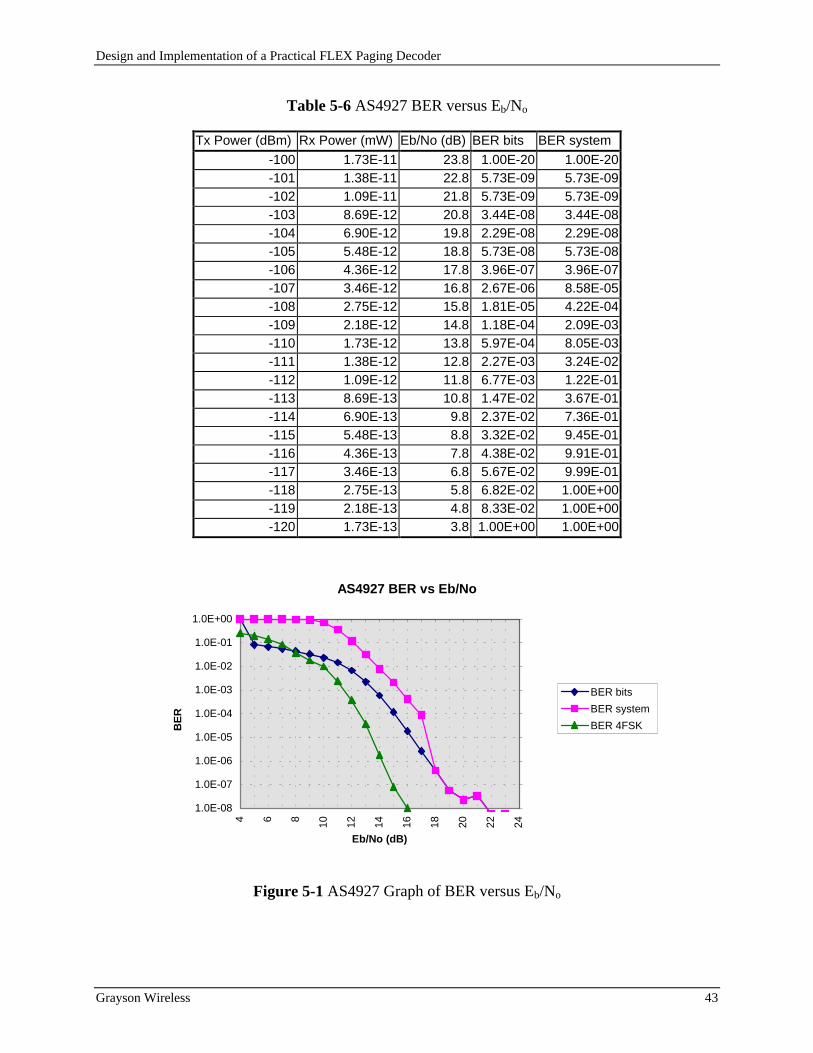
Design and Implementation of a Practical FLEX Paging Decoder
Grayson Wireless 43
Table 5-6 AS4927 BER versus Eb/No
Figure 5-1 AS4927 Graph of BER versus Eb/No
Tx Power (dBm) Rx Power (mW) Eb/No (dB) BER bits BER system
-100 1.73E-11 23.8 1.00E-20 1.00E-20-101 1.38E-11 22.8 5.73E-09 5.73E-09-102 1.09E-11 21.8 5.73E-09 5.73E-09-103 8.69E-12 20.8 3.44E-08 3.44E-08-104 6.90E-12 19.8 2.29E-08 2.29E-08-105 5.48E-12 18.8 5.73E-08 5.73E-08-106 4.36E-12 17.8 3.96E-07 3.96E-07-107 3.46E-12 16.8 2.67E-06 8.58E-05-108 2.75E-12 15.8 1.81E-05 4.22E-04-109 2.18E-12 14.8 1.18E-04 2.09E-03-110 1.73E-12 13.8 5.97E-04 8.05E-03-111 1.38E-12 12.8 2.27E-03 3.24E-02-112 1.09E-12 11.8 6.77E-03 1.22E-01-113 8.69E-13 10.8 1.47E-02 3.67E-01-114 6.90E-13 9.8 2.37E-02 7.36E-01-115 5.48E-13 8.8 3.32E-02 9.45E-01-116 4.36E-13 7.8 4.38E-02 9.91E-01-117 3.46E-13 6.8 5.67E-02 9.99E-01-118 2.75E-13 5.8 6.82E-02 1.00E+00-119 2.18E-13 4.8 8.33E-02 1.00E+00-120 1.73E-13 3.8 1.00E+00 1.00E+00
AS4927 BER vs Eb/No
1.0E-08
1.0E-07
1.0E-06
1.0E-05
1.0E-04
1.0E-03
1.0E-02
1.0E-01
1.0E+00
2422201816141210864
Eb/No (dB)
BE
R
BER bits
BER system
BER 4FSK
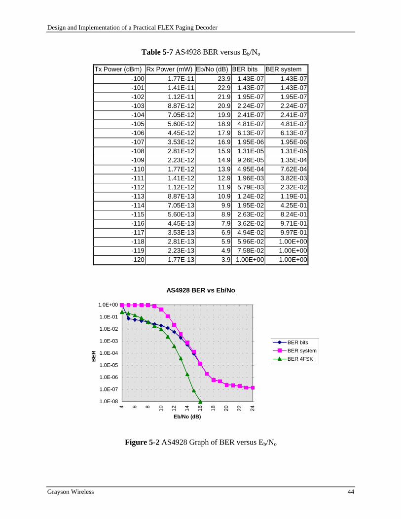
Design and Implementation of a Practical FLEX Paging Decoder
Grayson Wireless 44
Table 5-7 AS4928 BER versus Eb/No
Figure 5-2 AS4928 Graph of BER versus Eb/No
Tx Power (dBm) Rx Power (mW) Eb/No (dB) BER bits BER system
-100 1.77E-11 23.9 1.43E-07 1.43E-07-101 1.41E-11 22.9 1.43E-07 1.43E-07-102 1.12E-11 21.9 1.95E-07 1.95E-07-103 8.87E-12 20.9 2.24E-07 2.24E-07-104 7.05E-12 19.9 2.41E-07 2.41E-07-105 5.60E-12 18.9 4.81E-07 4.81E-07-106 4.45E-12 17.9 6.13E-07 6.13E-07-107 3.53E-12 16.9 1.95E-06 1.95E-06-108 2.81E-12 15.9 1.31E-05 1.31E-05-109 2.23E-12 14.9 9.26E-05 1.35E-04-110 1.77E-12 13.9 4.95E-04 7.62E-04-111 1.41E-12 12.9 1.96E-03 3.82E-03-112 1.12E-12 11.9 5.79E-03 2.32E-02-113 8.87E-13 10.9 1.24E-02 1.19E-01-114 7.05E-13 9.9 1.95E-02 4.25E-01-115 5.60E-13 8.9 2.63E-02 8.24E-01-116 4.45E-13 7.9 3.62E-02 9.71E-01-117 3.53E-13 6.9 4.94E-02 9.97E-01-118 2.81E-13 5.9 5.96E-02 1.00E+00-119 2.23E-13 4.9 7.58E-02 1.00E+00-120 1.77E-13 3.9 1.00E+00 1.00E+00
AS4928 BER vs Eb/No
1.0E-08
1.0E-07
1.0E-06
1.0E-05
1.0E-04
1.0E-03
1.0E-02
1.0E-01
1.0E+00
2422201816141210864
Eb/No (dB)
BE
R
BER bits
BER system
BER 4FSK

Design and Implementation of a Practical FLEX Paging Decoder
Grayson Wireless 45
5.5 Analysis
As Figure 5-1 and Figure 5-2 show, the difference between ideal and the system BER is between
3 and 4 dB. The reason that the bit BER (BER from usable codewords only) is better than ideal
for Eb/No less than 8 dB is the fact the number of bit errors that can detected is 3, so the
maximum possible bit BER is 9.4e-2 (3 divided by 32). The bit BER of 1.0 at Eb/No equal to 4
dB is when no usable codewords were decoded. The bit BER and system BER are the same for
high Eb/No (>15 for AS4928 and >17 for AS4927). This is expected since the probability of
multiple bits in error for a single codeword is extremely low. Once these diverge, the bit BER
clips to its maximum value of 9.4e-2 but the system BER continues on the expected curve. The
system BER is very pessimistic. The calculation of an erasure on the system BER is that the
entire codeword is in error. This leads to a BER greater than 0.5. If the system BER used 50%
bits in error instead of 100% for an erasure then the system BER would approach 0.5. The
reason that this work chose to error the entire codeword was the fact that pagers cannot process
codewords that have 0.5 BER. A pager can actually only process codewords that have 2 bits in
error since it can correct those bit errors. The results are expected and simply provide a measure
of the performance of the designed paging decoder.
Design and Implementation of a Practical FLEX Paging Decoder
Grayson Wireless 46
6. Conclusion
The author’s contribution-s in this work have been with the design, implementation, and
verification of a FLEX paging decoder. The receiver design that is briefly discussed in this thesis
is not the author’s work. The design of the receiver was given so that uniform perform
measurements (Eb/No) on the receiver/decoder pair could be made. The author designed the
digital decoder and implemented all the software needed to decode a FLEX data frame. This
software includes microprocessor assembly code and PC based high level code. The Appendix
lists all software that the author is permitted to publish. This work also presents in a clear
manner how to implement bit error rate measurements on a real system and to normalize the
results using Eb/No so that comparison to theoretical can be performed.
The design and implementation of a practical FLEX paging decoder has been presented. The
performance of the receiver decoder pair was 3 to 4 dB from ideal. The performance may
actually be closer to ideal if measurement error occurred. This is especially true with the noise
bandwidth calculation. If a false peak noise measurement occurred, then the noise bandwidth
would be calculated as too narrow. Additional work might be needed to investigate this possible
problem. The approach of using a microprocessor and a few discrete components has been
shown to provide acceptable performance. Additional work to better the BER might be to
examine the front end filter on the decoder to ensure that the maximum amount of usable signal
is provided with the minimum amount of noise. It is the classic problem of more bandwidth
gives more information but also provides more noise. Another item that needs more
investigation is the symbol clock timing. The sampling clock may be accurate over one FLEX
frame so that once the data in the frame is synchronized no sample clock adjustments are needed.
This would prevent the sampling clock from experiencing excessive jitter that could result in
slipping a symbol.
Design and Implementation of a Practical FLEX Paging Decoder
Grayson Wireless 47
7. References
[Ber 68] Berlekamp, Elwyn R., Algebraic Coding Theory, McGraw-Hill Book Company, 1968.
[Bli 76] Blinchikoff Herman J., Zverev Anatol I., Filtering in the Time and Frequency Domains,
John Wiley & Sons, Inc., 1976.
[Col 85] Collin, Robert E., Antennas and Radiowave Propagation, McGraw-Hill, Inc., 1985.
[Cou 90] Couch, Leon W., Digital and Analog Communications Systems, 3rd Edition, Macmillan
Publishing Company, 1990.
[Cro 76] Crow, E.L., Miles, M.J., “A Minimum Cost Accurate Statistical Method to Measure Bit
Error Rates,” Int. Conf. Computer Comm. Rec., pp.631-635, 1976.
[Dal 93] Dallas Semiconductor, 1992-1993 Product Data Book, Supplement-Microcontrollers,
pp.1-26
[Fun 91] Fung Victor, “Bit Error Simulation of FSK, BPSK, and π/4 DQPSK in Flat and
Frequency-Selective Fading Mobile Radio Channels using Two-Ray and Measurement-Based
Impulse Response Models,” Masters Thesis in Electrical Engineering, Virginia Polytechnic
Institute and State University, Blacksburg, Virginia, August 1991.
[Gra 71] Graeme Jerald G., Tobey Gene E., Huelsman Lawrence P., Operational Amplifiers
Design and Applications, McGraw-Hill Book Company, 1971.
[Hp 93] Hewlett Packard, OHP VEE Reference, Hewlett Packard Company, 1993.
[Lat 89] Lathi, B.P., Modern Digital and Analog Communication Systems, 2nd Edition, Holt,
Rinehart and Winston, Inc., 1989
[Lin 83] Lin, Shu, Costello, Daniel J. Jr., Error Control Coding: Fundamentals and
Applications, Prentice-Hall Inc., 1983.

Design and Implementation of a Practical FLEX Paging Decoder
Grayson Wireless 48
[Mac 77] MacWilliams, F.J., Sloane, N.J.A., The Theory of Error-Correcting Codes, Part I,
North-Holland Publishing Company, 1977.
[Mot 94] Motorola, “FLEX: Flexible High Speed Paging Protocol Benchmarking”, 1994.
[Phi 96] Philips Semiconductors, Data Handbook IC17, pp.431-438, 1996.
[Rap 96] Rappaport Theodore S., Wireless Communications Principles and Practices, Prentice
Hall PTR, 1996.
[Ste 96a] Stewart Lynn, “Paging technology: Systems and services,” Mobile Radio Technologies,
pp.26-28, February 1996.
[Ste 96b] Stewart Lynn, “Paging technology: Flex, ERMES paging codes,” Mobile Radio
Technologies, pp.22-30, April 1996.
[Wal 94] Walton Ron, Gorden Bill, “Better Stronger Faster,” Communications, Vol 31, Issue 1,
pp.29-32, January 1994.
Design and Implementation of a Practical FLEX Paging Decoder
Grayson Wireless 49
8. Appendix - Code Listings
/**********************************************************************//* Program NOISEBW.CPP/*/* Equivalent Noise Bandwidth Program/*/* Purpose: Given the file of the spectrum analzer data compute the/* noise bandwidth. File format is 401 lines of text. Each/* contains the power in dBm at that point. The frequency span/* of the analyzer was 50 KHz. The analyzer had 10 major divisions./* Each division represented 5 KHz and contained 40 points. This/* gives 400 points so the last point is to complete the whole/* 50 Khz span./*/* The frequency at each point is 425 KHz + n * 5KHz/40./* n=0 gives 425 KHz (first point at beginning of sweep)/* n=400 gives 475 MHz (last point at beginning of sweep)/*/* Assumption: See purpose/*/* Compiler: BorlandC++ version 4.52/*/* Scott McCulley/* Grayson Wireless/* Copyright 1997/**********************************************************************/
#include <stdio.h>#include <stdlib.h>#include <time.h>#include <values.h>#include <string.h>#include <dos.h>#include <math.h>#include <conio.h>
#define MAX_DATA 401
/* Global variable*/double specData[MAX_DATA];
/**********************************************************************//* loadSpecData/*/* Purpose: Load the global variable with the data from the passed in file/**********************************************************************/int loadSpecData(char *filename)
FILE *specDataFile;
if ((specDataFile=fopen(filename,"rt")) == NULL) printf("Error file %s does not exist.\n", filename);return -2;
for (int i=0; i<MAX_DATA; i++) fscanf(specDataFile,"%lf\n",&specData[i]);
// printf("Data at %d is %5.3le\n",i,specData[i]);// getch();
fclose(specDataFile);return 0;
/**********************************************************************//* dbm2mW/*/* Purpose: Return the passed in dBm value in mW/**********************************************************************/double dbm2mW(double dbm)
double mW;

Design and Implementation of a Practical FLEX Paging Decoder
Grayson Wireless 50
/* power dbm = 10 log(power mW / 1 mW) *//* power dbm / 10 = log(power mW / 1 mW) *//* 10 ^ (power dbm / 10) mW = power mW
/* raise dbm to 10 power y=10^x --- ln(y) = x ln(10) ---*//* y = exp( x ln(10)) --- ln() == log()*/mW = exp( (dbm/10.0) * log(10.0));
return mW;
/**********************************************************************//* calculateNoiseBw/*/* Purpose: Find the max value in global variable specData. Compute total power./* Get width of rectangle by dividing total power by max value./**********************************************************************/double calculateNoiseBw(void)/* frequency = 425 KHz + n * 5KHz/40. */
int i;double maxData=-1000.0, sum=0.0, bw=0.0;
/* find max in specData */for (i=0;i<MAX_DATA;i++)
maxData = max(specData[i],maxData);
printf("The max value is %7.2lf dBm or %5.3le mW.\n",maxData,dbm2mW(maxData));
/* integrate over entire data */for (i=0;i<MAX_DATA;i++)
sum += (dbm2mW(specData[i]) * 125); //125 Hz = 5 KHz/ 40
printf("The integrated sum over all values is %5.3le mW Hz.\n",sum);
bw = sum / dbm2mW(maxData);/*
for (i=195; i<205; i++) printf("The noise bw using point %d=%7.2lf dBm is %6.0lf Hz.\n",i, specData[i],sum /
dbm2mW(specData[i]));
*/return bw;
/**********************************************************************//* main/*/* Purpose: Get file name from the command line and call loadSpecData./* Then call calculateNoiseBw and show result./**********************************************************************/void main(void)
int result=0;double bw=0.0;char filename[255];
if (_argc < 2) printf("USAGE: NOISEBW [FILENAME]\n");result = -1;
// printf("argurements 0)%s 1)%s 2)%s\n",_argv[0], _argv[1], _argv[2]);strcpy(filename,_argv[1]);printf("Filename is %s\n",filename);if (!result)
result = loadSpecData(filename);
if (!result) bw=calculateNoiseBw();printf("The noise bw for file %s is %6.0lf Hz.\n",filename,bw);
exit(result);

Design and Implementation of a Practical FLEX Paging Decoder
Grayson Wireless 51
/************************************************/* Program: FLEX.CPP/*/* Flex Random Cycle Generator for HP 8648A/*/* Purpose: Command line interface to preform one of the following/*/* USAGE: FLEX [I,R,S,E] [NUM,AMPL] [RATE]/* I=Initialize/* R=Generate new random data. Save to file FLXrxxxx.RND where r is RATE and xxxx is NUM/* S=Start Flex Data at give AMPLitude (negative dBm assumed) at RATE ('1'-'4')/* E=Stop Flex Data./*/* "I" sends a set of initializations strings to HP 8648A for set-up/*/* "R" Generate a random flex cycle. The frame information is unique for each/* of the 128 frames generated. All data codewords in the interleaved blocks are/* randomly generate the 21 data bits and then perform BCH and even parity to complete/* each 32-bit codeword. Random data is saved to a file and sent to HP8648A./* Codewords are NOT send interleaved. The HP8648A adds the correct SYNC1, SYNC2 and/* handles the block interleaving./*/* "S" Starts the HP8648A at a give amplitude to send the flex cycle./*/* "E" Stops the HP8648A from sending the flex cycle./*/* Assumption: HP 8648A on address 18. HPIB perform with National Instruments/* PCMCIA card for DOS Version 2.7.2. AT-GPIB/TNT software used because running/* with Windows 95 or any AT-GPIB. Code will work also work on National Instruments/* AT-GPIB card installed in desktop PC/*/* Compiler: BorlandC++ version 4.52/*/* Scott McCulley/* Grayson Wireless/* Copyright 1997/************************************************/
#include <stdio.h>#include <stdlib.h>#include <time.h>#include <values.h>#include <string.h>#include <dos.h>#include "w_instr.h" //Grayson Header file for HPIB communication
#define SENDTOHPIB;//#define WRITEHPIBFILE //Text file of all data sent over HPIB (debug)//#define ECHOINFO //Progress written to screen (debug)#define LAST_FRAME 127 //Last frames to generate. Should be 127//#define WRITETXT //Text file of random FLEX data generated (debug)
/*GLOBAL VARIABLES*/#ifdef SENDTOHPIB
Instr hp8648a; //Instr class. Grayson Library Class written to//communicate via HPIB. Code not provided.
#endif
/*****************************************************************************/* function bch31_21_parity_plus_even/*/* Purpose: Given the 21 data bits generate the 10 parity bits and even parity/* bit and return the 32 codeword with data in 21 MSB, bch parity in next 10 and/* even parity in LSB/*****************************************************************************/unsigned long bch31_21_parity_plus_even(unsigned long data)const
polynominal= 0x369; // 11101101001b = X^10+X^9+X^8+X^6+X^5+X^3+1
unsigned long savedata=data,working=0;int i;if (data >= 0x200000l) //illegal to have data > 11 bits
exit;for (i=0;i<21;i++) working *= 2; //shift left by one data *= 2; //shift left by one //data in working bits 0 to 9 check bit 10 if ( ((working >> 10) & 1) != ((data >> 21) & 1) )

Design and Implementation of a Practical FLEX Paging Decoder
Grayson Wireless 52
//bit location 0 - 20 is data 21 is check bitworking ^= polynominal;
working &= 0x3FF; //save only last 10 bits data &= 0x1FFFFFl; //save only last 21 bits
// printf("data is %lX and parity is %lX\n",savedata,working);savedata = ((savedata << 11) & 0xFFFFF800l) | ((working << 1) & 0x7FE);//parity is in LSB of save data and it is 0for (i=1; i<32; i++)
if ((savedata >> i) & 1) // if bit at ith posistion is setsavedata ^= 1; //complement the lsb
return savedata;
/*****************************************************************************//* function invert/*/* Purpose: Given a 32 unsigned long int. Invert data bits bit 31 to bit 0,/* bit 30 to bit 1, etc./*****************************************************************************/unsigned long invert(unsigned long data)
unsigned long invertedData=0;for (int i=0;i<32;i++)
invertedData |= ((data >> (31 - i)) & 1) << i;return invertedData;
/*****************************************************************************//* function sendHpib/*/* Purpose: Send string to hp6448a (if defined) and write to file (if defined)./*****************************************************************************/void sendHpib(char *hpibStr)#ifdef WRITEHPIBFILE
FILE *hpib;#endif
#ifdef SENDTOHPIBhp8648a.Send(hpibStr);
#endif
#ifdef WRITEHPIBFILEif ( (hpib=fopen("flexhpib.dat","a+t")) == NULL)
printf("Error output file not created.\n");exit(-1);
fprintf(hpib,"%s\n",hpibStr);fclose(hpib);
#endif
/*****************************************************************************//* function initializeHP8648A/*/* Purpose: initialize the HP8648A with the following/* FREQUENCY: 930.0000 MHZ/* FM DEVIATION: 4.80 KHz/* AUTOMATC ATTENUATOR: ON/* AMPLITUDE: -80 dBM/* RF: ON/* DIGITAL MODULATION: ON/* FORMAT: FLEX/* POLARITY: NORMAL/* FILTER: ON/* MESSAGE NUMBER: 0/* START FRAME: 0/* STOP FRAME: 127/* MODE: CONT/* IMMEDIATE STOP: ON/*/*****************************************************************************/void initializeHP8648A(void)

Design and Implementation of a Practical FLEX Paging Decoder
Grayson Wireless 53
char hpibStr[255];//from Chapter 2 in HP8648A manual
sprintf(hpibStr,"FREQ:CW 930.00000 MHZ");sendHpib(hpibStr);
sprintf(hpibStr,"DM:DEV 4.8 KHZ");sendHpib(hpibStr);
sprintf(hpibStr,"POW:ATT:AUTO ON");sendHpib(hpibStr);
sprintf(hpibStr,"POW:AMPL -80 dBm");sendHpib(hpibStr);
sprintf(hpibStr,"OUTP:STAT ON");sendHpib(hpibStr);
sprintf(hpibStr,"DM:STAT ON");sendHpib(hpibStr);
sprintf(hpibStr,"PAG:SEL FLEX");sendHpib(hpibStr);
sprintf(hpibStr,"DM:POL NORM");sendHpib(hpibStr);
sprintf(hpibStr,"DM:FILT:STAT ON");sendHpib(hpibStr);
sprintf(hpibStr,"PAG:FLEX:MESS:SEL 0");sendHpib(hpibStr);
sprintf(hpibStr,"PAG:FLEX:ARB:STAR 0");sendHpib(hpibStr);
sprintf(hpibStr,"PAG:FLEX:ARB:STOP %d",LAST_FRAME);sendHpib(hpibStr);
sprintf(hpibStr,"TRIG:COUN 0"); //trigger count 0 is continous modesendHpib(hpibStr);
sprintf(hpibStr,"PAG:FLEX:IST:STAT ON");sendHpib(hpibStr);
delay(1000);
/*****************************************************************************//* function startFlex/*/* Purpose: send tp the HP8648A with the following/* AMPLITUDE: inputted amplitudeStr (amp in dBm with negative sign implide/* FORMAT: FLEX/* DATA RATE: 6400/4, 3200/4, 3200/2, 1600/2 based on inputted rate char/* START ENCODING/*****************************************************************************/void startFlex(char *amplitudeStr, char rate)
char hpibStr[255], rateStr[10], fskStr[10];//from Chapter 2 in HP8648A manual
sprintf(hpibStr,"POW:AMPL -%s dBm", amplitudeStr);sendHpib(hpibStr);
switch (rate) case '4':
strcpy(rateStr,"6400");strcpy(fskStr,"FSK4");break;
case '3':strcpy(rateStr,"3200");strcpy(fskStr,"FSK4");break;
case '2':strcpy(rateStr,"3200");strcpy(fskStr,"FSK2");break;
case '1':strcpy(rateStr,"1600");

Design and Implementation of a Practical FLEX Paging Decoder
Grayson Wireless 54
strcpy(fskStr,"FSK2");break;
default:printf("Error Rate not valid.\n");
#ifdef SENDTOHPIBhp8648a.Close();hp8648a.CloseAll();
#endifexit(-1);
sprintf(hpibStr,"PAG:FLEX:RATE %s",rateStr);sendHpib(hpibStr);
sprintf(hpibStr,"DM:FORM %s",fskStr);sendHpib(hpibStr);
delay(2000);
sprintf(hpibStr,"INIT:IMM");sendHpib(hpibStr);
typedef struct unsigned long int frameInfo;unsigned long int blockData[352]; flexBlock;
/*****************************************************************************//* function writeRandomArb/*/* Purpose: send tp the HP8648A with the following/* DIGITAL MODULATION: ON/* FORMAT: FLEX/* DATA RATE: 6400/4, 3200/4, 3200/2, 1600/2 based on inputted rate char/* MESSAGE NUMBER: 0/*/*****************************************************************************/void writeRandomArb(char *numStr, char rate)#ifdef WRITETXT
FILE *textFile;#endif
FILE *binFile;int i,frame=0, maxCw;unsigned long lsb14,msb7;unsigned long flexData, frameInfo;flexBlock *pFlexBlock;char s[255], fileNameStr[255];char hpibStr[255], rateStr[10], fskStr[10];//from Chapter 2 in HP8648A manual
switch (rate) case '4':
strcpy(rateStr,"6400");strcpy(fskStr,"FSK4");maxCw = 352;break;
case '3':strcpy(rateStr,"3200");strcpy(fskStr,"FSK4");maxCw = 176;break;
case '2':strcpy(rateStr,"3200");strcpy(fskStr,"FSK2");maxCw = 176;break;
case '1':strcpy(rateStr,"1600");strcpy(fskStr,"FSK2");maxCw = 88;break;
default:printf("Error Rate not valid.\n");
#ifdef SENDTOHPIBhp8648a.Close();hp8648a.CloseAll();
#endifexit(-1);

Design and Implementation of a Practical FLEX Paging Decoder
Grayson Wireless 55
sprintf(hpibStr,"PAG:FLEX:RATE %s",rateStr);sendHpib(hpibStr);
sprintf(hpibStr,"DM:FORM %s",fskStr);sendHpib(hpibStr);
delay(1000);
randomize();#ifdef WRITETXT
sprintf(fileNameStr,"..\\data\\flx%c%s.TXT",rate,numStr);if ( (textFile=fopen(fileNameStr,"wt")) == NULL)
printf("Error text output file %s not created.\n", fileNameStr);exit(-1);
#endif
sprintf(fileNameStr,"..\\data\\flx%c%s.RND",rate,numStr);if ( (binFile=fopen(fileNameStr,"wb")) == NULL)
printf("Error binary output file %s not created.\n", fileNameStr);exit(-1);
//from page 2-26 in HP8648A manual//lsb16 = 0 msb16=16926 : cycle 0 frame 0 collapse 0 repeat 0 t 0xF
pFlexBlock = new (flexBlock);
while (frame <= LAST_FRAME)
#ifdef ECHOINFOprintf("Forming and sending flex frame %d\n", frame);
#endif
#ifdef SENDTOHPIBhp8648a.EnableEOT(0);
#endif//FI = xxxx 0000 ffff fff0 0000 0 c=0, n=0, r=0, t=0//xxxx = 1's complement fff0 + fffflsb14 = (frame & 0xF) + ((frame >> 4) & 0x7);lsb14 = (lsb14 ^ 0xF) & 0xF;msb7 = ((frame << 8) & 0x7F00) | lsb14;frameInfo = (invert(msb7) >> 11);
// printf("frame: %d, x is 0x%04lX, fi is 0x%06lX invert fi is 0x%06lX\n", frame, lsb14, msb7,frameInfo);
frameInfo = bch31_21_parity_plus_even(frameInfo);frameInfo = invert(frameInfo);
// frameInfo is equal to ((unsigned long)(16926) << 16) & (unsigned long)(0xFFFF0000)// printf("Frame Info %08lX\n",frameInfo);
sprintf(hpibStr,"PAG:FLEX:ARB:DEF");sprintf(s," %d, %d",frame, (frameInfo >> 16) & 0xFFFF);strcat(hpibStr,s);sprintf(s, ", %d", frameInfo & 0xFFFF);strcat(hpibStr,s);
#ifdef WRITETXTfprintf(textFile,"FRAME %03d\n",frame);fprintf(textFile,"FI=%08lX\n",frameInfo);
#endifpFlexBlock->frameInfo = frameInfo;
for (i=0; i<maxCw; i++)
sendHpib(hpibStr);strcpy(hpibStr,"");
lsb14 = random(0x4000); //return random number between 0 and 0x3FFFmsb7 = random(0x80); //return random number between 0 and 0x7FflexData = (msb7 << 14) | lsb14;
// printf("lsb14 %lX msb7 %lX flexdata %08lX\n", lsb14, msb7, flexData);flexData = bch31_21_parity_plus_even(flexData);flexData = invert(flexData);
//had problem with Borland the msb and lsb conversion of flexData could not//be done on the same line
sprintf(s, ", %d", (flexData >> 16) & 0xFFFF );strcat(hpibStr,s);sprintf(s, ", %d", flexData & 0xFFFF );strcat(hpibStr,s);

Design and Implementation of a Practical FLEX Paging Decoder
Grayson Wireless 56
/* printf("flex %08lX = msb16 %04lX lsb16 %04lX ", flexData,(flexData >> 16) & 0xFFFF, flexData & 0xFFFF );
printf("Decimal MSB %d, ", ((flexData >> 16) & 0xFFFF) );printf("LSB %d\n", (flexData & 0xFFFF) );
*/#ifdef WRITETXT
fprintf(textFile,"%08lX\n",flexData);#endif
pFlexBlock->blockData[i] = flexData;
#ifdef ECHOINFOprintf("Completed flex frame %d\n", frame);
#endif
if (fwrite(pFlexBlock, sizeof(flexBlock), 1, binFile)!=1) printf("Error can not write to binary output file.\n");exit(-1);
#ifdef SENDTOHPIBhp8648a.EnableEOT(1);
#endifsendHpib(hpibStr);frame++;
delete(pFlexBlock);
#ifdef WRITETXTfclose(textFile);
#endiffclose(binFile);
delay(2000); //wait 0.5 second so that data is processed
/*****************************************************************************//* function stopEncoding/*/* Purpose: send tp the HP8648A with the following/* STOP ENCODING/*/*****************************************************************************/void stopEncoding(void)
char hpibStr[255];//from Chapter 2 in HP8648A manual
sprintf(hpibStr,"ABOR");sendHpib(hpibStr);
/*****************************************************************************//* function main/*/* Purpose: Examine command line parameters and call appropriate function/*/*****************************************************************************/void main(void)
int result=0;#ifdef SENDTOHPIB
hp8648a.Init(19);#endif
if (_argc < 2) printf("USAGE: FLEX [I,R,S,E] [NUM,AMPL] [RATE]\n");printf(" I=Initialize\n");printf(" R=Generate new random data. Save to file FLXrxxxx.RND where r is RATE and xxxx
is NUM\n");printf(" S=Start Flex Data at give AMPLitude (negative dBm assumed) at RATE ('1'-
'4')\n");printf(" E=Stop Flex Data.\n");result = -1;
if (!result)switch (_argv[1][0])
Design and Implementation of a Practical FLEX Paging Decoder
Grayson Wireless 57
case 'I':initializeHP8648A();break;
case 'R':if (_argc<2)
printf("Error File Number not given.\n");result = -1;break;
if (_argc<3)
printf("Error Rate not given.\n");result = -1;break;
writeRandomArb(_argv[2],_argv[3][0]);break;
case 'S':if (_argc<2)
printf("Error Amplitude not given.\n");result = -1;break;
if (_argc<3)
printf("Error Rate not given.\n");result = -1;break;
startFlex(_argv[2],_argv[3][0]);break;
case 'E':stopEncoding();break;
default:printf("Error invalid usage.\n");result = -1;
#ifdef SENDTOHPIBhp8648a.Close();hp8648a.CloseAll();
#endif
exit(result);

Design and Implementation of a Practical FLEX Paging Decoder
Grayson Wireless 58
/************************************************/* Program: ANALZER.CPP/*/* Flex BER Analyzer 8648A/*/* Purpose: Compare FLEXxxxx.RND files with mesaure data, where xxxx is a number/* between 0000 and 9999. This number is used to identify which random sequence/* was used in FLEX transmission. The measure data files are of the format/* RrFfxxxx.aaa where r is the receiver number (1 to 4), f is the flex data rate/* (1=1600-2FSK, 2=3200-2FSK, 3=3200-4FSK, 4=6400-4FSK), xxxx is the random sequence/* received, and aaa is amplitude of generator (range 090 to 120 negative sign remove)./*/* Assumption: files FLEXxxxx.RND generated by file FLEX.EXE and files RrFfxxxx.aaa/* collected with Pagetracker Pro Version 3.23.20 with _BERTEST_ defined in/* standards.inc/*/* Compiler: BorlandC++ version 4.52/*/* Scott McCulley/* Grayson Wireless/* Copyright 1997/************************************************/#include <stdio.h>#include <stdlib.h>#include <time.h>#include <values.h>#include <string.h>#include <dos.h>#include <conio.h>
/* 128 exact data contents for files FLEXxxxx.RND */typedef struct
unsigned long int frameInfo;unsigned long int blockData[352]; flexBlock;
/* from 0 to 128 of this data structure for files RrFfxxxx.aaa */typedef struct
unsigned char rate; //0=1600-2, 1=3200-2, 2=3200-4, 3=6400-4unsigned char An_Errs[2]; //Bit errors for each pattern in sync1 detectedunsigned long int frameInfo; //Data in bits 20-0, errored bits in bits 22-21unsigned char C_Errs[2]; //Bit errors for each pattern in sync2 detectedunsigned long int blockData[352]; //Data in bits 20-0, errored bits in bits 22-21unsigned char result; //0=Frame OK, 1 =Frameinfo errored, 4=comma errored,
//5=comma* errored measuredFlexBlock;
/* results */typedef struct
double usableCodewordBits[2]; //0=total bits, 1=errored bitsdouble codewordErasures[2]; //0=total codewords, 1=erasure cwdouble frameErasures[3]; //0=total frames, 1=erasure from An,
//2=errors from comma//Total frames is always 128//Total codewords is always (TotalFrames-erasures) * 352//Total bits is always (TotalCodewords-erasures) * 32
resultsFlexBlock;
/* Global Variables */flexBlock *pFlexCycle[128]; //one flex cyle is 128 flex framesunsigned char rxUsed[4][4]; //1st[4] is receiver, 2nd[4] is rate.
//initialized to 1 once RrFfxxxx.aaa is not found//see to 0 so if not processed any more
resultsFlexBlock results[4][4][31]; //1st[4] is receiver 0-3, //2nd[4] is rate where 0=1600-2FSK, //1=3200-2FSK, 2=3200-4FSK, 3=6400-4FSK, //[31] is dbm where 0=90dBm, //1=91dBm, ... 30=120dBm
#define START_DBM 0 //should be 0#define STOP_DBM 20 //should be 30 for (-90 to -120) or 20 for (-100 to -120)#define DBM_OFFSET 100 //offset to bring START_DBM to actual dbm should be 90
// or 100(negative implided)#define START_FRAME 0 //should be 0#define STOP_FRAME 127 //should be 127#define START_NUM 0 //should be 0#define STOP_NUM 9999 //should be 9999#define START_RX 0 //should be 0#define STOP_RX 3 //should be 3#define DISPLAY_DBM -105 //all dbm less than this value will display errors

Design and Implementation of a Practical FLEX Paging Decoder
Grayson Wireless 59
//TRACE_02 to _04
//below are trace statements that are enabled if the trace number is not zero//these are only for debug purposes. The needch for some of the traces requires//a user to press a key to continue the program.int TRACE_01= 0; //trace frame number, frame read, FI, rx frameint TRACE_02= 0; //trace BCH errorsint NEEDCH_02= 0; //need ch to continue after BCH errorint TRACE_03= 0; //trace comma errorsint NEEDCH_03= 0; //need ch to continue after comma errorint TRACE_04= 0; //Trace erasures codewordsint NEEDCH_04= 0; //need ch to continue after cw erasureint TRACE_05= 1; //Trace extra data in fileint NEEDCH_05= 0; //after extra data in fileint NEEDCH_06= 0; //Every 9 frames wait for user inputint TRACE_07= 0; //trace missed framesint NEEDCH_07= 0; //need ch to continue after missed frameint TRACE_08= 0; //trace erasures that have no BCH errorint NEEDCH_08= 0; //need ch to continue erasure w/ no BCH errsint TRACE_09= 0; //trace Frame Info problemsint NEEDCH_09= 0; //need ch to continue after frame info problems
/*prototypes*/void allocateAndInitVars(void);void freeMemory(void);
/************************************************/* masterExists/*/* Purpose: returns 1 if file exists otherwise return 0/* File name is based on numStr and rateCh/************************************************/int masterExists(char *numStr, char rateCh)
FILE *binFile;char fileNameStr[255];
sprintf(fileNameStr,"..\\data\\FLX%c%s.RND",rateCh,numStr);if ( (binFile=fopen(fileNameStr,"rb")) == NULL)
// printf("Error binary output file %s does not exist.\n", fileNameStr);return(0);
fclose(binFile);
return(1);
/************************************************/* loadMaster/*/* Purpose: Fills the global variable pFlexCycle with data in master file that/* contains frameinfo and random codewords sent by HP8648A for this number and rate/************************************************/int loadMaster(char *numStr, char rateCh)
FILE *binFile;char fileNameStr[255];int frame=START_FRAME;
// int cw;
sprintf(fileNameStr,"..\\data\\FLX%c%s.RND",rateCh,numStr);if ( (binFile=fopen(fileNameStr,"rb")) == NULL)
printf("Error binary output file %s does not exist.\n", fileNameStr);return(-1);
while (frame <= STOP_FRAME) if (fread(pFlexCycle[frame], sizeof(flexBlock), 1, binFile)!=1)
printf("Error can not read frame %d from %s.\n", frame, fileNameStr);fclose(binFile);return(-1);
/*
for (cw=0;cw<352;cw++) if ( (pFlexCycle[frame]->blockData[cw] & 0x1FFFFFl) == 0x053FE7l)
printf("Num:%s Frame:%d cw:%d is %06lX\n",numStr, frame, cw, (pFlexCycle[frame]->blockData[cw] & 0x1FFFFFl));

Design and Implementation of a Practical FLEX Paging Decoder
Grayson Wireless 60
printf("Num:%s Frame:%d cw:%d is %06lX\n",numStr, frame-1, cw, (pFlexCycle[frame-1]->blockData[cw] & 0x1FFFFFl));
*/frame++;
fclose(binFile);
return(0);
/************************************************/* berResult/*/* Purpose: Return 1 if data is ok. Otherwise return -1./* For the number specificed, the rate and amplitude is traversed through./* Only one rate is processed (3=6400-4). The file that the PAGETRACKER Pro software/* logged for each amplitude is examined. Results are tallied in global variable results/************************************************/int berResult(char *numStr)/* RrFfxxxx.aaa where r is the receiver number (1 to 4), f is the flex data rate
(1=1600-2FSK, 2=3200-2FSK, 3=3200-4FSK, 4=6400-4FSK), xxxx is the random sequencereceived, and aaa is amplitude of generator (range 090 to 120 negative sign remove). */
FILE *binFile;char fileNameStr[255], amplitudeStr[4], rateCh, rxNumCh, ch=' ';int rate, frame=START_FRAME, cw, rxFrame, rxNum, framesRead=0, fCount,displayCount, lastCount;int dbm;int infoDisplayed=0;unsigned char cont;measuredFlexBlock rxFlexBlock;
for (rate=0; rate<4; rate++) cont=1; //assume continue for (rxNum=START_RX; rxNum<=STOP_RX; rxNum++)
if (rxUsed[rxNum][rate]) //if all receiver are not used then continue in loop cont=0; //this receive is used so no continue statement
if (cont) //if all receivers not used continue in loopcontinue;
rateCh = '1'+(char)(rate); if (loadMaster(numStr, rateCh) == 0)
printf("Analazing number %s rate %c\n",numStr, rateCh); else
for (rxNum=START_RX; rxNum<=STOP_RX; rxNum++) rxUsed[rxNum][rate]=0; //all receivers at this rate are not used continue in loop
continue;
;
for (rxNum=START_RX; rxNum<=STOP_RX; rxNum++) if (!rxUsed[rxNum][rate]) //if receiver not used continue in loop
continue;dbm=START_DBM;rxNumCh = '1'+(char)(rxNum);printf("Receiver %c rate %c ", rxNumCh, rateCh);
while (dbm <= STOP_DBM) sprintf(amplitudeStr,"%03d",dbm+DBM_OFFSET);sprintf(fileNameStr,"..\\data\\R%cF%c%s.%s",rxNumCh,rateCh,numStr,amplitudeStr);if ( (binFile=fopen(fileNameStr,"rb")) == NULL)
printf("not used because file %s does not exist.\n", fileNameStr);// return(-1);
rxUsed[rxNum][rate] = 0; //RrFfxxxx.aaa is not found so set to falsedbm = STOP_DBM+1;continue;
if (dbm == START_DBM) printf("proccessing.\n");
frame=START_FRAME;framesRead=0;fCount = 0;displayCount=0;

Design and Implementation of a Practical FLEX Paging Decoder
Grayson Wireless 61
while (fCount < (STOP_FRAME-START_FRAME+1)) if (TRACE_01) printf("Frame:%d Frame Read:%d Frame Count:%d ", frame,framesRead,fCount);if (fread(&rxFlexBlock, sizeof(measuredFlexBlock), 1, binFile)!=1)
if (TRACE_01) printf("Can not read %d frame(s) from %s.\n", (STOP_FRAME-START_FRAME+1-fCount), fileNameStr);// getch();
while (fCount < (STOP_FRAME-START_FRAME+1)) results[rxNum][rate][dbm].frameErasures[0]++; //total framesresults[rxNum][rate][dbm].frameErasures[1]++; //erasure by Anif (TRACE_07) printf("Missed frame %d\n", frame);if (NEEDCH_07) getch();frame++;if (frame>STOP_FRAME) frame = START_FRAME;fCount++;
continue;
else
//because HP8648A TX is not settled for first frame ignore this frame//this frame will be processed after frame 127 is receivedif ( (frame == START_FRAME) && (framesRead==0) )
if (TRACE_01) printf("1st frame ignored\n");frame++;if (frame>STOP_FRAME) frame = START_FRAME;framesRead++;continue;
framesRead++;fCount++;if (fCount > (STOP_FRAME-START_FRAME+1))
if (TRACE_05) printf("Extra data in file %s.\n", fileNameStr );if (NEEDCH_05) getch();continue;
rxFrame = int ((rxFlexBlock.frameInfo >> 8) & 0x7F);if (TRACE_01) printf("FI:%08lX rxFrame:%d\n", rxFlexBlock.frameInfo, rxFrame );if (ch=='s') ch=getch();
if ((frame != rxFrame) && ((rxFlexBlock.result == 0) || (rxFlexBlock.result == 4)|| (rxFlexBlock.result == 5)) ) //here rxFrame is valid to use
// printf("dBm:%d; Num:%s; On frame %d; rx frame %d; Frame Read %d; Frame Count%d.\n", -(dbm+DBM_OFFSET), numStr, frame, rxFrame, framesRead, fCount );// frame information has 3 errors they invalidate or if frame is less than excepted frame exceptfor frame 0
if ( (((rxFlexBlock.frameInfo >> 21) & 0x3)==3) || (((framesRead > rxFrame) || (rxFrame < frame)) && (rxFrame !=0)) ) if (TRACE_09)
printf("dBm:%d; Invalid FI=%08lX; errs=%ld; rx frame=%d Frame Read=%d FrameCount=%d\n", -(dbm+DBM_OFFSET), rxFlexBlock.frameInfo,
((rxFlexBlock.frameInfo >> 21) & 0x3), rxFrame, framesRead, fCount );if (NEEDCH_09) getch();rxFlexBlock.result = 1; //make this invalid FI
results[rxNum][rate][dbm].frameErasures[0]++; //total framesif (rxFlexBlock.result > 0)
//result = 1 then Frameinfo errored. 4=comma errored, 5=comma* erroredif (rxFlexBlock.result > 3)
lastCount=fCount;while ( (frame != rxFrame) && (fCount < (STOP_FRAME-START_FRAME+1)) )
results[rxNum][rate][dbm].frameErasures[0]++; //total framesresults[rxNum][rate][dbm].frameErasures[1]++; //erasure by Anif (TRACE_07) printf("Missed frame %d\n", frame);if (NEEDCH_07) getch();frame++;if (frame>STOP_FRAME) frame = START_FRAME;fCount++;
if (fCount > (STOP_FRAME-START_FRAME+1))
continue;if ((TRACE_01) && (lastCount!=fCount))printf("Now Frame:%d Frame Read:%d Frame
Count:%d FI:%08lX rxFrame:%d\n", frame,framesRead,fCount,rxFlexBlock.frameInfo, rxFrame);

Design and Implementation of a Practical FLEX Paging Decoder
Grayson Wireless 62
results[rxNum][rate][dbm].frameErasures[2]++; //erasure by Commaif (( (-(dbm+DBM_OFFSET)) > (DISPLAY_DBM)) && (TRACE_03))
printf("dBm:%d; Frame %d erased by comma.\n", -(dbm+DBM_OFFSET), frame);if (NEEDCH_03) getch();
else
results[rxNum][rate][dbm].frameErasures[1]++; //erasure by Anif (TRACE_07) printf("Frame %d erased by Corrupt FI.\n", frame);if (NEEDCH_07) getch();
else
//adjust frame count and frame to match current received frameif (rxFlexBlock.result == 0)
// e.g. FRAME 034 FI=FDA0220B //lastCount=fCount;while ( (frame != rxFrame) && (fCount < (STOP_FRAME-START_FRAME+1)) )
results[rxNum][rate][dbm].frameErasures[0]++; //total framesresults[rxNum][rate][dbm].frameErasures[1]++; //erasure by Anif (TRACE_07) printf("Missed frame %d\n", frame);if (NEEDCH_07) getch();frame++;if (frame>STOP_FRAME) frame = START_FRAME;fCount++;
if (fCount > (STOP_FRAME-START_FRAME+1))
continue;if ((TRACE_01) && (lastCount!=fCount))printf("Now Frame:%d Frame Read:%d Frame
Count:%d FI:%08lX rxFrame:%d\n", frame,framesRead,fCount,rxFlexBlock.frameInfo, rxFrame);
//here valid frame examine codewordsframe=rxFrame;results[rxNum][rate][dbm].codewordErasures[0] += 352; //total codeword in flex
frameinfoDisplayed=0;ch=' ';for (cw=0;cw<352;cw++)
if ( (rxFlexBlock.blockData[cw] & 0x1FFFFFl) == (pFlexCycle[frame]->blockData[cw] & 0x1FFFFFl) ) results[rxNum][rate][dbm].usableCodewordBits[0] += 32; //total bitsresults[rxNum][rate][dbm].usableCodewordBits[1] += (double)
( (rxFlexBlock.blockData[cw] >> 21) & 0x3); //error bitsif (infoDisplayed)
// printf("%d.\n", cw-1);infoDisplayed=0;
if ( ( (rxFlexBlock.blockData[cw] >> 21) & 0x3) > 0)
if (( (-(dbm+DBM_OFFSET)) > (DISPLAY_DBM) ) && (TRACE_02)) printf("dBm:%d; frame:%d; cw %d has %ld errors.\n", -(dbm+DBM_OFFSET),
frame, cw, (rxFlexBlock.blockData[cw] >> 21) & 0x3);if (NEEDCH_02) getch();
else
results[rxNum][rate][dbm].codewordErasures[1]++; //erasured codewordif ( ( (-(dbm+DBM_OFFSET)) > (DISPLAY_DBM) ) && (ch != 'c') && (TRACE_04))
printf("dBm %d; Frame %d; cw %d erasured; rxCw:%06lX rxErr:%ldrandCw:%06lX\n", -(dbm+DBM_OFFSET),rxFrame, cw, (rxFlexBlock.blockData[cw] & 0x1FFFFFl),(rxFlexBlock.blockData[cw] >> 21) & 0x3,(pFlexCycle[frame]->blockData[cw] & 0x1FFFFFl));
if (NEEDCH_04) ch = getch();
if (TRACE_08 && ( ((rxFlexBlock.blockData[cw] >> 21) & 0x3) == 0)) //error bits
printf("Eras w/ no errs. frame:%d cw:%d rx:%08lX <> rand:%08lXXOR:%08lX\n",
frame, cw, rxFlexBlock.blockData[cw], pFlexCycle[frame]->blockData[cw],
rxFlexBlock.blockData[cw] ^ (pFlexCycle[frame]->blockData[cw] & 0x1FFFFFl) );if ((NEEDCH_08) && (ch!='c')) ch = getch();
;
if (!infoDisplayed) // printf("dBm %d; Frame %d; cw %d to ", -(dbm+DBM_OFFSET),rxFrame, cw);
infoDisplayed=1;
Design and Implementation of a Practical FLEX Paging Decoder
Grayson Wireless 63
if (infoDisplayed)
// printf("%d.\n", cw-1);infoDisplayed=0;
/* if ((rxFlexBlock.result == 0) || (rxFlexBlock.result == 4)|| (rxFlexBlock.result == 5)) */
frame++;if (frame>STOP_FRAME) frame = START_FRAME;
if ( (NEEDCH_06) && (fCount>displayCount) )
printf("Press any key to continue\n");getch();displayCount=fCount+8;
fclose(binFile);dbm++;
// end rxNum for loop // end rate for loop
return(1);
/************************************************/* safeDivide/*/* Purpose: If numerator is 0 then return 1 is denominator is also 0 otherwise return 0./* If numerator not 0 and denominator is 0 then return 1 otherwise return denominator/numerator./************************************************/double safeDivide(double num, double denom)
if (num==0.0)if (denom==0.0)
return 1.0;else
// return 1e-16;return 0.0;
elseif (denom==0.0)
return 1.0;else
return (num / denom);
/************************************************/* saveResults/*/* Purpose: Write the values in global variable results to a text file./************************************************/void saveResults(void)
int dbm;int rate;int rxNum;double bitsBer=0.0,cwErr=0.0,frameErr=0.0, blockBer=0.0, systemBer=0.0;char fileNameStr[255];FILE *txtFile;
for (rate=0; rate<4; rate++) for (rxNum=START_RX; rxNum<=STOP_RX; rxNum++)
dbm=START_DBM;if ( !results[rxNum][rate][dbm].frameErasures[0])
continue; //if no frames collected write not result filesprintf(fileNameStr,"..\\result\\R%cF%cRSLT.TXT",'1'+(char)(rxNum), '1'+(char)(rate) );
if ( (txtFile=fopen(fileNameStr,"wt")) == NULL) printf("Error text output file %s does not exist.\n", fileNameStr);txtFile = stdout;

Design and Implementation of a Practical FLEX Paging Decoder
Grayson Wireless 64
printf("Saving results for receiver %c rate %c\n",'1'+(char)(rxNum), '1'+(char)(rate));fprintf(txtFile,"Receiver %c rate %c\n",'1'+(char)(rxNum), '1'+(char)(rate));fprintf(txtFile,
" Tx | Usable CW bits |Codeword Erasures| Fame Erasures | BER | BER | BER | BER |BER \n");
fprintf(txtFile,//"Powr|Tot.Bits|Errored |Tot. CWs|Erasures| Total | An | Comma|\n");"Powr|Tot.Bits|Errored |Tot. CWs|Erasures| Tot | An |Comma| bits | CWs | frame | block |system \n");
for (dbm=START_DBM;dbm<=STOP_DBM;dbm++) bitsBer =
safeDivide(results[rxNum][rate][dbm].usableCodewordBits[1],results[rxNum][rate][dbm].usableCodewordBits[0]);
cwErr =safeDivide(results[rxNum][rate][dbm].codewordErasures[1],results[rxNum][rate][dbm].codewordErasures[0]);
frameErr =safeDivide(results[rxNum][rate][dbm].frameErasures[1]+results[rxNum][rate][dbm].frameErasures[2],results[rxNum][rate][dbm].frameErasures[0]);
blockBer =safeDivide(results[rxNum][rate][dbm].usableCodewordBits[1]+results[rxNum][rate][dbm].codewordErasures[1]*32.0,results[rxNum][rate][dbm].codewordErasures[0]*32.0);
systemBer =safeDivide(results[rxNum][rate][dbm].usableCodewordBits[1]+results[rxNum][rate][dbm].codewordErasures[1]*32.0+((results[rxNum][rate][dbm].frameErasures[1]+results[rxNum][rate][dbm].frameErasures[2])*352.0*32.0),results[rxNum][rate][dbm].frameErasures[0]*352.0*32.0);
fprintf(txtFile,"-%03d|%8.2le|%8.2le|%8.2le|%8.2le|%5.0lf|%5.0lf|%5.0lf|%8.2le|%8.2le|%8.2le|%8.2le|%8.2le\n",(dbm+DBM_OFFSET),results[rxNum][rate][dbm].usableCodewordBits[0],results[rxNum][rate][dbm].usableCodewordBits[1],results[rxNum][rate][dbm].codewordErasures[0],results[rxNum][rate][dbm].codewordErasures[1],results[rxNum][rate][dbm].frameErasures[0],results[rxNum][rate][dbm].frameErasures[1],results[rxNum][rate][dbm].frameErasures[2],bitsBer,cwErr,frameErr,blockBer, systemBer);
fclose(txtFile); //end for rxNum loop
//end for rate loop
/************************************************/* main/*/* Purpose: Allocate memory and initialize variables. Loop through all randomally/* generated cycle and call berResults. Call saveResults to write to a file./************************************************/void main(void)
char* numStr="0000";int num;
// int rate, rxNum;unsigned char brk=0; //no break
allocateAndInitVars();
for (num=START_NUM;num<=STOP_NUM;num++) sprintf(numStr,"%04d",num);if (masterExists(numStr, '1') || masterExists(numStr, '2') ||
masterExists(numStr, '3') || masterExists(numStr, '4') ) berResult(numStr);
/* old waybrk=1; //assume breakfor (rxNum=START_RX; rxNum<=STOP_RX; rxNum++)
for (rate=0; rate<4; rate++)if (rxUsed[rxNum][rate]) //if all receiver in all rates are not used then break
brk=0; //this receive is used so no break statement*/
else
brk=1; //breakif (brk) //if receiver not used continue in loop
break;
saveResults();

Design and Implementation of a Practical FLEX Paging Decoder
Grayson Wireless 65
// printf("Complete Ber Result\n");// getch();
freeMemory();
/************************************************/* allocateAndInitVars/*/* Purpose: Allocate memory and initialize global variable results/************************************************/void allocateAndInitVars(void)
printf("Allocating memory\n");for (int frame=START_FRAME;frame<=STOP_FRAME;frame++)
pFlexCycle[frame] = new (flexBlock);
printf("Initilize variables\n");for (int rxNum=START_RX;rxNum<=STOP_RX;rxNum++)
for (int rate=0;rate<4;rate++) for (int dbm=START_DBM;dbm<=STOP_DBM;dbm++)
results[rxNum][rate][dbm].usableCodewordBits[0] = 0.0;results[rxNum][rate][dbm].usableCodewordBits[1] = 0.0;results[rxNum][rate][dbm].codewordErasures[0] = 0.0;results[rxNum][rate][dbm].codewordErasures[1] = 0.0;results[rxNum][rate][dbm].frameErasures[0] = 0.0;results[rxNum][rate][dbm].frameErasures[1] = 0.0;results[rxNum][rate][dbm].frameErasures[2] = 0.0;
rxUsed[rxNum][rate] = 1; //assume all used
/************************************************/* freeMemory/*/* Purpose: Free all allocated memory variables/************************************************/void freeMemory(void)// printf("Destroying memory\n");
for (int frame=START_FRAME;frame<=STOP_FRAME;frame++) delete (pFlexCycle[frame]);

Design and Implementation of a Practical FLEX Paging Decoder
Grayson Wireless 66
9. Vita
Scott Lindsey McCulley
Scott Lindsey McCulley was born on August 26, 1969, in Wilmington, Delaware. He grew up in
the area and graduated from Salesianum High School in 1988. Scott obtained a Bachelor of
Science in Electrical Engineering with a Math Minor from Virginia Polytechnic Institute and
State University in 1992. He graduated with Honors and Magna Cum Laude. Scott went on to
pursue a master degree in the same field and complete all course work by 1993. In the summer
of 1993, he went to work as the Director of Engineering for TSR Technologies, a company that
Dr. T.S. Rappaport founded. In the fall of 1993, TSR Technologies was sold to Grayson
Wireless, formerly Grayson Electronics. Scott is currently working for Grayson Wireless, the
sponsor of this research, as a Product Development Engineer. He has helped design and
implement numerous measurement and test equipment and software for the wireless industry,
including paging, cellular, and PCS.