design and implementation of an automotive experimental
TRANSCRIPT

IN DEGREE PROJECT INFORMATION AND COMMUNICATION TECHNOLOGY,SECOND CYCLE, 60 CREDITS
, STOCKHOLM SWEDEN 2017
Design and implementation of an automotive experimental platform for ADAS
VIKTOR KARLQUIST
KTH ROYAL INSTITUTE OF TECHNOLOGYSCHOOL OF INFORMATION AND COMMUNICATION TECHNOLOGY

Design and implementation of an automotiveexperimental platform for ADAS
Viktor Karlquist
Master of Science Thesis
Embedded SystemsSchool of Information and Communication Technology
KTH Royal Institute of Technology
Stockholm, Sweden
3 February 2017
Examiner: Zhonghai LuSupervisor: Yuan Yao

© Viktor Karlquist, 3 February 2017

Abstract
Road fatalities are decreasing every year. A major reason is the increased presenceand the increased complexity of Advanced Driver Assistance Systems (ADAS).ADAS are becoming one of the biggest research areas in the automotive industry.This thesis presents a design and implementation of an automotive experimentalplatform for ADAS.
The thesis provides an overview of automotive concepts related to ADAS,such as Electronic Control Unit (ECU), commonly used communication protocolsin cars and Operating Systems (OS) used for automotive purposes. In addition ageneral background to ADAS is presented as well as an introduction to the stateof the art technology.
The design of the platform is presented with a detailed hardware descriptionas well as a thorough motivation to the design choices. The design consists ofmultiple ECUs connected through a switched Ethernet network with multipleswitches. The design also includes a model car equipped with actuators andsensors, made to mimic a real car.
Several functions have been implemented in the system such as reading sensordata, controlling actuators and a control interface to control the car. As a proof-of-concept platform the resulting system can be exploited and flexibly extendedfor various ADAS functions and safety engineering.
i

Sammanfattning
Antalet dodsolyckor minskar for varje ar. En stor anledning till detta ar den okandeforekomsten och okande komplexiteten av Advanced Driver Assistance Systems(ADAS). ADAS ar pavag att bli ett av de storsta forskningsomradena inombilindustrin. Den har masteruppsatsen presenterar en design och implementationav en experimentell plattform for ADAS.
Uppsatsen ger en overblick av concept relaterade till ADAS, sasom ElectronicControl Unit (ECU), vanligt forekommande kommunikationsprotokoll i bilar ochOperativ System (OS) anvanda i bilindustrin. Dessutom presenteras en generellbeskrivning av vad ADAS ar och vad som ar den senaste teknologin inom ADAS.
Designen av platformen beskrivs med en detaljerat hardvaru-beskrivninglikval nogranna motiveringar till designvalen. Designen bestar av ett flertanECU:er ihopkopplade genom ett switchat Ethernet-natverk med multipla switchar.En del av designen bestar ocksa av en modell-bil utrustad med sensorer ochmotorer, for att efterlikna en riktig bil.
Ett flertal implementation presenteras, sasom inlasning av sensordata, kontrollav motorer och ett kontrollgransnitt for att styra modellbilen. Resultatet avuppsatsen ar ett forsta forsok till en design och implementation av en platform.Platformen ar ett proof-of-concept som mojliggor for flexibla tillagg och sakerhetstestning.
ii

Acknowledgements
I would like to acknowledge my examiner and advisers support throughout thethesis. I would also like to thank KTH Service Center for assisting with purchasesof components.
iii

Contents
1 Introduction 11.1 Problem description . . . . . . . . . . . . . . . . . . . . . . . . . 21.2 Goals . . . . . . . . . . . . . . . . . . . . . . . . . . . . . . . . 21.3 Ethics and Sustainability . . . . . . . . . . . . . . . . . . . . . . 31.4 Research method . . . . . . . . . . . . . . . . . . . . . . . . . . 31.5 Development methodology . . . . . . . . . . . . . . . . . . . . . 41.6 Structure of this thesis . . . . . . . . . . . . . . . . . . . . . . . 4
2 Background 52.1 Electronic Control Unit . . . . . . . . . . . . . . . . . . . . . . . 5
2.1.1 Microcontroller . . . . . . . . . . . . . . . . . . . . . . . 62.1.2 Microprocessor . . . . . . . . . . . . . . . . . . . . . . . 6
2.2 Advanced Driver Assistance Systems . . . . . . . . . . . . . . . 72.2.1 Sensors . . . . . . . . . . . . . . . . . . . . . . . . . . . 82.2.2 Sensor fusion . . . . . . . . . . . . . . . . . . . . . . . . 92.2.3 Cooperating vehicles . . . . . . . . . . . . . . . . . . . . 92.2.4 Vehicle-to-Infrastructure Communication . . . . . . . . . 10
2.3 Autonomous cars . . . . . . . . . . . . . . . . . . . . . . . . . . 112.4 Communication protocols in cars . . . . . . . . . . . . . . . . . . 12
2.4.1 LIN . . . . . . . . . . . . . . . . . . . . . . . . . . . . . 122.4.2 CAN . . . . . . . . . . . . . . . . . . . . . . . . . . . . 132.4.3 Flexray . . . . . . . . . . . . . . . . . . . . . . . . . . . 132.4.4 Ethernet . . . . . . . . . . . . . . . . . . . . . . . . . . . 14
2.4.4.1 CSMA/CD . . . . . . . . . . . . . . . . . . . . 152.4.4.2 Loop-prevention . . . . . . . . . . . . . . . . . 162.4.4.3 AVB/TSN . . . . . . . . . . . . . . . . . . . . 172.4.4.4 802.1Q VLAN . . . . . . . . . . . . . . . . . . 20
2.5 The real-time concept . . . . . . . . . . . . . . . . . . . . . . . . 212.6 Operating systems . . . . . . . . . . . . . . . . . . . . . . . . . . 21
2.6.1 AUTOSAR . . . . . . . . . . . . . . . . . . . . . . . . . 222.6.2 Embedded Linux . . . . . . . . . . . . . . . . . . . . . . 24
iv

CONTENTS v
2.6.2.1 Linux Real-time Scheduler . . . . . . . . . . . 242.6.2.2 PREEMPT RT Patch . . . . . . . . . . . . . . 24
2.7 Related work . . . . . . . . . . . . . . . . . . . . . . . . . . . . 25
3 Hardware and software tools 263.1 Hardware . . . . . . . . . . . . . . . . . . . . . . . . . . . . . . 26
3.1.1 BeagleBone Black . . . . . . . . . . . . . . . . . . . . . 263.1.1.1 Sitara AM3358 chipset . . . . . . . . . . . . . 27
3.1.2 Peripherals . . . . . . . . . . . . . . . . . . . . . . . . . 303.1.3 Device Tree . . . . . . . . . . . . . . . . . . . . . . . . . 323.1.4 Serial to USB interface - SparkFun FTDI Basic Breakout . 323.1.5 Raspberry Pi 3 model B . . . . . . . . . . . . . . . . . . 32
3.1.5.1 RPI dedicated camera . . . . . . . . . . . . . . 333.1.6 TP-link TL-SG105E Network Switch . . . . . . . . . . . 353.1.7 Model Car . . . . . . . . . . . . . . . . . . . . . . . . . 36
3.1.7.1 Servo motor . . . . . . . . . . . . . . . . . . . 383.1.7.2 Brushless motor . . . . . . . . . . . . . . . . . 383.1.7.3 ESC . . . . . . . . . . . . . . . . . . . . . . . 39
3.1.8 Android device . . . . . . . . . . . . . . . . . . . . . . . 393.1.9 Sensors . . . . . . . . . . . . . . . . . . . . . . . . . . . 39
3.1.9.1 Ultra Sonic Sensor, HC-SR04 . . . . . . . . . 393.1.9.2 Reflective sensor, OPB715Z OPTO SWITCH . 403.1.9.3 Motion sensor, MPU-9250 . . . . . . . . . . . 40
3.2 Operating System . . . . . . . . . . . . . . . . . . . . . . . . . . 403.2.1 Linux 4.4-ti-rt . . . . . . . . . . . . . . . . . . . . . . . . 413.2.2 Linux 4.4-rt . . . . . . . . . . . . . . . . . . . . . . . . . 41
3.3 Software tools . . . . . . . . . . . . . . . . . . . . . . . . . . . . 423.3.1 Wireshark . . . . . . . . . . . . . . . . . . . . . . . . . . 423.3.2 Android studio . . . . . . . . . . . . . . . . . . . . . . . 423.3.3 config-pin . . . . . . . . . . . . . . . . . . . . . . . . . . 423.3.4 Cyclictest . . . . . . . . . . . . . . . . . . . . . . . . . . 433.3.5 TI PRU C compiler . . . . . . . . . . . . . . . . . . . . . 433.3.6 Device Tree Compiler . . . . . . . . . . . . . . . . . . . 43
4 Design 444.1 Hardware . . . . . . . . . . . . . . . . . . . . . . . . . . . . . . 44
4.1.1 ECUs . . . . . . . . . . . . . . . . . . . . . . . . . . . . 444.1.2 Network switches . . . . . . . . . . . . . . . . . . . . . . 454.1.3 Sensors . . . . . . . . . . . . . . . . . . . . . . . . . . . 464.1.4 Model car, actuators and electronics . . . . . . . . . . . . 464.1.5 Android device . . . . . . . . . . . . . . . . . . . . . . . 47

CONTENTS vi
4.2 Choice of OS . . . . . . . . . . . . . . . . . . . . . . . . . . . . 474.3 Overview of the system architecture . . . . . . . . . . . . . . . . 48
5 Implementations 525.1 Car network and ECU to ECU communication . . . . . . . . . . . 525.2 Implementing the OS . . . . . . . . . . . . . . . . . . . . . . . . 54
5.2.1 BeagleBone ECU . . . . . . . . . . . . . . . . . . . . . . 545.2.2 Raspberry Pi ECU . . . . . . . . . . . . . . . . . . . . . 56
5.3 Sensors . . . . . . . . . . . . . . . . . . . . . . . . . . . . . . . 565.3.1 Ultra Sonic sensor . . . . . . . . . . . . . . . . . . . . . 56
5.4 Controlling actuators . . . . . . . . . . . . . . . . . . . . . . . . 595.4.1 Steering servo . . . . . . . . . . . . . . . . . . . . . . . . 595.4.2 ESC . . . . . . . . . . . . . . . . . . . . . . . . . . . . . 61
5.5 Network monitoring . . . . . . . . . . . . . . . . . . . . . . . . . 615.6 Control and monitoring interface . . . . . . . . . . . . . . . . . . 62
5.6.1 Android App . . . . . . . . . . . . . . . . . . . . . . . . 635.6.2 UDP server . . . . . . . . . . . . . . . . . . . . . . . . . 64
5.7 Error detection . . . . . . . . . . . . . . . . . . . . . . . . . . . 67
6 Conclusions 696.1 Summary . . . . . . . . . . . . . . . . . . . . . . . . . . . . . . 69
6.1.1 Goals . . . . . . . . . . . . . . . . . . . . . . . . . . . . 706.2 Future work . . . . . . . . . . . . . . . . . . . . . . . . . . . . . 70
6.2.1 Adding additional sensors . . . . . . . . . . . . . . . . . 706.2.2 Sensor fusion . . . . . . . . . . . . . . . . . . . . . . . . 716.2.3 Implement full AVB/TSN support . . . . . . . . . . . . . 716.2.4 Error detection . . . . . . . . . . . . . . . . . . . . . . . 716.2.5 Benchmarks . . . . . . . . . . . . . . . . . . . . . . . . . 726.2.6 Creating test scenarios . . . . . . . . . . . . . . . . . . . 726.2.7 Creating an API for external communication . . . . . . . 736.2.8 Improving the control and monitoring interface . . . . . . 74
Bibliography 75
A Code 85
List of Figures
2.1 Sensors and Electronics in ADAS, from [1] . . . . . . . . . . . . 82.2 Flex ray segments, taken from National Instruments [2]. . . . . . . 142.3 Example of a broadcast storm, from [3, Chapter 8] . . . . . . . . 162.4 Credit-based shaper algorithm, from [4] . . . . . . . . . . . . . . 192.5 An overview of AUTOSAR ECU Software Architecture, take
from [5] . . . . . . . . . . . . . . . . . . . . . . . . . . . . . . . 23
3.1 The BeagleBone Black board, taken from [6] . . . . . . . . . . . 273.2 Programming the PRU, image taken from [7] . . . . . . . . . . . 293.3 PRU-ARM message passing, taken from [8] . . . . . . . . . . . . 313.4 The Raspberry Pi 3 Model B board, taken from [9] . . . . . . . . 333.5 The Raspberry Pi Camera Module v2, taken from [10] . . . . . . 343.6 The TP-link TL-SG105E network switch, taken from [11] . . . . . 353.7 Turnigy SCT 2WD 1/10 Brushless Short Course Truck (KIT)
upgraded version, taken from [12] . . . . . . . . . . . . . . . . . 363.8 Controlling a servo motor . . . . . . . . . . . . . . . . . . . . . . 383.9 The HC-SR04 is a distance sensor, taken from [13] . . . . . . . . 403.10 pfifo fast queuing policy, taken from [14]. . . . . . . . . . . . . . 41
4.1 Network topology . . . . . . . . . . . . . . . . . . . . . . . . . . 494.2 Example of broken link . . . . . . . . . . . . . . . . . . . . . . . 494.3 Overview of the system architecture . . . . . . . . . . . . . . . . 50
5.1 Ultrasonic sensor algorithm . . . . . . . . . . . . . . . . . . . . . 575.2 Voltage dividing circuit . . . . . . . . . . . . . . . . . . . . . . . 595.3 Servo control algorithm . . . . . . . . . . . . . . . . . . . . . . . 605.4 Network monitoring program . . . . . . . . . . . . . . . . . . . . 625.5 Android application layout . . . . . . . . . . . . . . . . . . . . . 635.6 Package structure of packet sent from Android Application . . . . 645.7 Server receiving commands from the Android Application . . . . 655.8 Package structure of the data sent containing status . . . . . . . . 665.9 Mutex example . . . . . . . . . . . . . . . . . . . . . . . . . . . 66
vii

LIST OF FIGURES viii
5.10 Summary of the Control and Monitoring interface . . . . . . . . . 67
6.1 External communication possibilities . . . . . . . . . . . . . . . . 73

List of Tables
2.1 VLAN tag . . . . . . . . . . . . . . . . . . . . . . . . . . . . . . 20
3.1 BeagleBone Black hardware specification . . . . . . . . . . . . . 313.2 Raspberry Pi 3 Model B hardware specification . . . . . . . . . . 333.3 Priorities according to traffic type . . . . . . . . . . . . . . . . . 363.4 Components used to build the model car . . . . . . . . . . . . . . 37
ix

List of Listings
3.1 Config-pin example . . . . . . . . . . . . . . . . . . . . . . . . . 425.1 Vlan setup script . . . . . . . . . . . . . . . . . . . . . . . . . . 535.2 Config-pin example . . . . . . . . . . . . . . . . . . . . . . . . . 55A.1 Example code controlling multiple PWM signals . . . . . . . . . 85
x

List of Acronyms and Abbreviations
ADAS Advanced Driver Assistance System
API Application Programming Interface
ARM Advanced RISC Machine
AVB Audio Video Bridging
BBB BeagleBone Black
CAN Control Area Network
CPU Central Processing Unit
CSMA/CA Carrier Sense Multiple Access/Collision Avoidance
CSMA/CD Carrier Sense Multiple Access/Collision Detection
DSP Digital Signal Processor
ECU Electronic Control Unit
eMMC embedded MultiMediaCard
EU European Union
FPGA Field Programmable Array
GPOS General Purpose Operating System
IMU Inertial Measurement Unit
LIN Local Interconnect Network
OEM Original Equipment Manufacturer
OS Operating System
xi
LIST OF ACRONYMS AND ABBREVIATIONS xii
PRU Programmable Real-time Unit
PWM Pulse Width Modulation
QoS Quality of Service
RPI Raspberry Pi
RTOS Real-Time Operating System
RISC Reduced Instruction Set Computing
SoC System on a Chip
UDP User Datagram Protocol
TCP Transmission Control Protocol
TDMA Time division multiple access
TSN Time Sensitive Networking
VLAN Virtual Local Area Network

Chapter 1
Introduction
In 2015 the number of road related fatalities was over 26000, half of the number offatalities which occurred in 2001. It is a drastic decrease and the EU Commissionroad safety program aims to get these numbers even lower by the year 2020 [15].Traffic researcher Johann Gwehenberger predicted in 2010 that more than halfof the serious accidents in Europe could be prevented if ADAS were present[16]. Advanced Drivers Assistance Systems are the systems used to aid driverswhile driving [17] and it is one of the most rapidly growing research areas in theautomotive industry. Even though it is a huge research area for the automotivecompanies the annual revenues from ADAS are still very modest compared toother vehicle systems. One of the reasons is believed to be that many of theimplementations are still being refined and have not yet hit the market [18, p. 13].
Many of the available research platforms and solutions available are proprietaryand there is a need for an open source based platform which is available foreveryone; including students as well as researchers. There are a lot of differenttypes of ADAS on all different levels of complexity. There are very complexsystems that can map the environment with help of Radars and Lidars and thereare systems that can do depth image analysis with the help of stereo vision. Inaddition to the very complex systems there are also, somewhat, simpler systemssuch as parking assistance that can detect objects with range sensors [19].
This thesis focuses on designing and implementing a platform that allows forexperimenting with different ADAS in practice. The platform is a proof-of-concept and it provides the set of tools and functionality to implement differentfunctionalities of ADAS.
This chapter gives a general introduction to the research area, formulates aproblem description and discusses the goals of the thesis. It also presents theresearch and development methodologies as well as providing the structure of the
1
1.1. PROBLEM DESCRIPTION 2
thesis
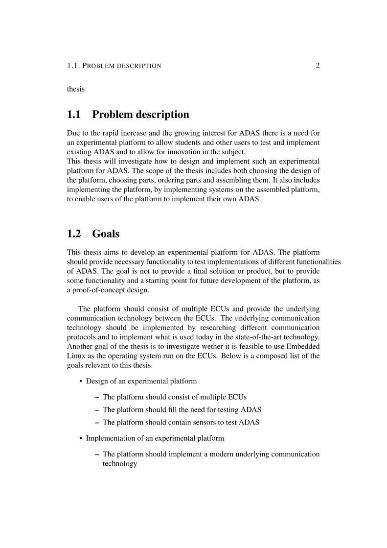
1.1 Problem descriptionDue to the rapid increase and the growing interest for ADAS there is a need foran experimental platform to allow students and other users to test and implementexisting ADAS and to allow for innovation in the subject.This thesis will investigate how to design and implement such an experimentalplatform for ADAS. The scope of the thesis includes both choosing the design ofthe platform, choosing parts, ordering parts and assembling them. It also includesimplementing the platform, by implementing systems on the assembled platform,to enable users of the platform to implement their own ADAS.
1.2 GoalsThis thesis aims to develop an experimental platform for ADAS. The platformshould provide necessary functionality to test implementations of different functionalitiesof ADAS. The goal is not to provide a final solution or product, but to providesome functionality and a starting point for future development of the platform, asa proof-of-concept design.
The platform should consist of multiple ECUs and provide the underlyingcommunication technology between the ECUs. The underlying communicationtechnology should be implemented by researching different communicationprotocols and to implement what is used today in the state-of-the-art technology.Another goal of the thesis is to investigate wether it is feasible to use EmbeddedLinux as the operating system run on the ECUs. Below is a composed list of thegoals relevant to this thesis.
• Design of an experimental platform
– The platform should consist of multiple ECUs
– The platform should fill the need for testing ADAS
– The platform should contain sensors to test ADAS
• Implementation of an experimental platform
– The platform should implement a modern underlying communicationtechnology

1.3. ETHICS AND SUSTAINABILITY 3
– There should be a way of controlling the platform externally
– There should exist functionality to get data from sensors
The result of the thesis should provide a physical platform on which the userof the platform can experiment with different types of ADAS by user softwarethat communicates with the implemented software.
1.3 Ethics and SustainabilityThe main ethical benefit of this platform is to create an open source platformavailable to anyone. This is also an issue, to make sure that the platform is fullyopen source by identifying the software and hardware used and their licenses. Itis also important to document the process to enable anyone to build and set up theplatform. Another issue, to keep the platform available to as many as possible, isto try and keep the cost of the platform down.
By making the platform highly extendable and available the platform can adaptto future technologies and enable for future development, creating a reusable andsustainable system.
1.4 Research methodThis section will start by giving an introduction to research methods and workmethods, followed by a motivation to what methods are used in this thesis.A research method can be classified as either quantitative or qualitative. Aquantitative method determines the credibility of a hypothesis by collecting a largeset of data to analyze it with statistics and other methods. A qualitative researchis to collect data and assess it subjectively [20].A research can also be divided into two different research approaches: deductiveand inductive methods. An inductive research approach is when facts and dataare collected and a theory or hypothesis is developed from the gathered data.Inductive methods tend to be qualitative. A deductive work method is when atheory is first presented and data is collected to verify and validate the theory[20].The main research methodology used in this thesis is qualitative, since the resultsare evaluated subjectively by a few persons. The research approach is mainlyinductive, since there is no hypothesis to be proven at the beginning of the thesis.Data is collected in order to design the platform, as there is no known design priorto the work.
1.5. DEVELOPMENT METHODOLOGY 4
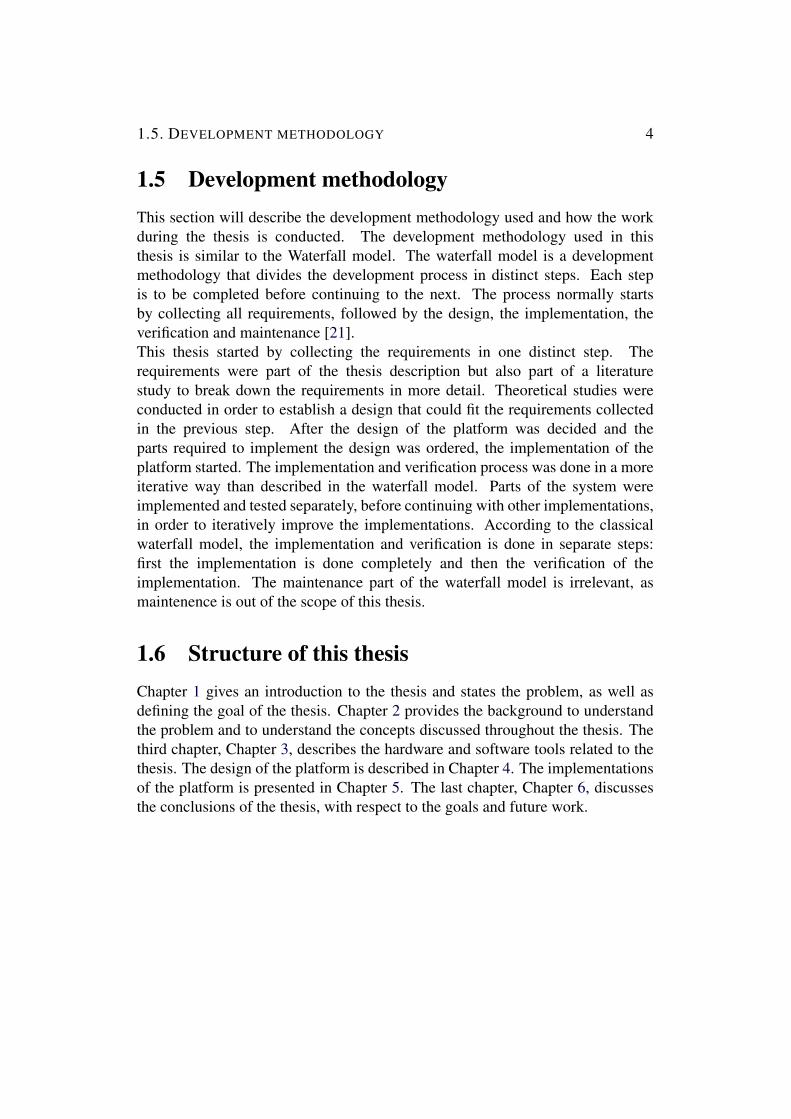
1.5 Development methodologyThis section will describe the development methodology used and how the workduring the thesis is conducted. The development methodology used in thisthesis is similar to the Waterfall model. The waterfall model is a developmentmethodology that divides the development process in distinct steps. Each stepis to be completed before continuing to the next. The process normally startsby collecting all requirements, followed by the design, the implementation, theverification and maintenance [21].This thesis started by collecting the requirements in one distinct step. Therequirements were part of the thesis description but also part of a literaturestudy to break down the requirements in more detail. Theoretical studies wereconducted in order to establish a design that could fit the requirements collectedin the previous step. After the design of the platform was decided and theparts required to implement the design was ordered, the implementation of theplatform started. The implementation and verification process was done in a moreiterative way than described in the waterfall model. Parts of the system wereimplemented and tested separately, before continuing with other implementations,in order to iteratively improve the implementations. According to the classicalwaterfall model, the implementation and verification is done in separate steps:first the implementation is done completely and then the verification of theimplementation. The maintenance part of the waterfall model is irrelevant, asmaintenence is out of the scope of this thesis.
1.6 Structure of this thesisChapter 1 gives an introduction to the thesis and states the problem, as well asdefining the goal of the thesis. Chapter 2 provides the background to understandthe problem and to understand the concepts discussed throughout the thesis. Thethird chapter, Chapter 3, describes the hardware and software tools related to thethesis. The design of the platform is described in Chapter 4. The implementationsof the platform is presented in Chapter 5. The last chapter, Chapter 6, discussesthe conclusions of the thesis, with respect to the goals and future work.

Chapter 2
Background
This chapter will provide the necessary background of the thesis. The chapterwill start by introducing what an Electronic Control Unit is and provide severalexamples of such controllers. The next thing to be described is Advanced DriverAssistance Systems, it will provide several examples of implementations and ageneral description of what it is. This will be followed by a brief introductionto autonomous cars, in particular a case study of Google’s self driving car.Furthermore the most common communication protocols used in cars will bepresented together with a new modern approach using Ethernet. Next, the conceptof real-time will be briefly introduced, to provide a necessary background to real-time theory. This is followed by a look into Operating Systems in embeddedsystems and in particular operating systems used in the automotive industry. Thelast part of this chapter will discuss some related work to this thesis.
2.1 Electronic Control UnitAn Electronic Control Unit (ECU) is the term for any embedded system thatcontrols an electrical system in a vehicle [22]. The number of ECUs in carsis drastically increasing. The amount of average ECUs in a car is expected tobe above 40 units by year 2019. This amount is twice as much as it was in2010, where the number of average ECUs in a car was merely 20 [23, p. 29].An ECU can be, as previously stated, any embedded system that controls anelectrical system. It can be anything from a simple circuit to a computer. Thissection will focus on Microcontrollers and Microprocessors used in automotiveindustry, but it is important to understand that other types of control units in carsexists, for example DSPs and FPGAs. Before diving into the two different typesof embedded systems it is important to clarify the difference between the two.
5

2.1. ELECTRONIC CONTROL UNIT 6
A Microcontroller typically has on-chip flash memory, which means it canload the program quickly and be up and running in short time. By having anon-chip memory a microcontroller is also limited to a finite amount of memoryand typically has a maximum memory of 2 Megabytes. A microprocessor on theother hand does not have this constraint as it has a separate memory for storingprograms and data. This means that typically a microcontroller can be up andrunning faster but have access to less memory [24].
2.1.1 MicrocontrollerThere are several different types of microcontrollers used in todays cars. Onemajor supplier of microcontrollers for the automotive industry is Atmel. Theyoffer a lot of different solutions based on the AVR 8-bit and 32-bit RISC designs.The controllers have applications ranging from controlling the electrical mirrorsto infotainment applications [25]. Another supplier is Microchip with their wellknown PIC microcontrollers. There are a lot of different PIC microcontrollers,but they are all based on the Harvard architecture with RISC instruction set design[26]. The two families of microcontrollers share that they both use RISC design,which is a trend that will continue for the automotive industry [27].
2.1.2 MicroprocessorAs algorithms are becoming more and more complex there is a need for lowcost high performance CPUs [27]. One major supplier of Microprocessors inthe automotive industry is Texas Instruments. They have more than 150 millionsolutions integrated in vehicles today, in more than 35 different original equipmentmanufacturers (OEM). They provide solutions for both ADAS, which will bedescribed in detail in Chapter 2.2, and Infotainment [28]. Common for thesolutions they provide is that the main processing unit used in the systemsare different version of ARM processors based on the ARM architecture [29].Another major supplier is NXP that offers a lot of different solutions for theautomotive industry [30]. Most of their solutions uses microprocessors areimplemented using different processors based on the ARM architecture andanother popular architecture named POWER architecture [31].
ARM is currently the leading architecture for microprocessors in the automotiveindustry according to IHF [30] next to the POWER architecture.
2.2. ADVANCED DRIVER ASSISTANCE SYSTEMS 7
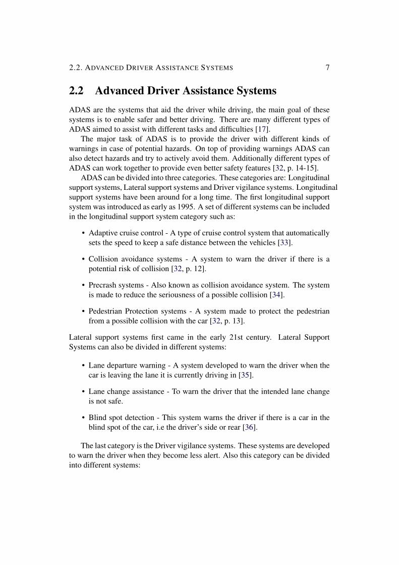
2.2 Advanced Driver Assistance SystemsADAS are the systems that aid the driver while driving, the main goal of thesesystems is to enable safer and better driving. There are many different types ofADAS aimed to assist with different tasks and difficulties [17].
The major task of ADAS is to provide the driver with different kinds ofwarnings in case of potential hazards. On top of providing warnings ADAS canalso detect hazards and try to actively avoid them. Additionally different types ofADAS can work together to provide even better safety features [32, p. 14-15].
ADAS can be divided into three categories. These categories are: Longitudinalsupport systems, Lateral support systems and Driver vigilance systems. Longitudinalsupport systems have been around for a long time. The first longitudinal supportsystem was introduced as early as 1995. A set of different systems can be includedin the longitudinal support system category such as:
• Adaptive cruise control - A type of cruise control system that automaticallysets the speed to keep a safe distance between the vehicles [33].
• Collision avoidance systems - A system to warn the driver if there is apotential risk of collision [32, p. 12].
• Precrash systems - Also known as collision avoidance system. The systemis made to reduce the seriousness of a possible collision [34].
• Pedestrian Protection systems - A system made to protect the pedestrianfrom a possible collision with the car [32, p. 13].
Lateral support systems first came in the early 21st century. Lateral SupportSystems can also be divided in different systems:
• Lane departure warning - A system developed to warn the driver when thecar is leaving the lane it is currently driving in [35].
• Lane change assistance - To warn the driver that the intended lane changeis not safe.
• Blind spot detection - This system warns the driver if there is a car in theblind spot of the car, i.e the driver’s side or rear [36].
The last category is the Driver vigilance systems. These systems are developedto warn the driver when they become less alert. Also this category can be dividedinto different systems:

2.2. ADVANCED DRIVER ASSISTANCE SYSTEMS 8
• Attention or Drowsiness Assistance - Tries to capture the drivers alertnessand warn the driver if it is diminishing [32, p. 12].
• Alcohol lock - To prevent drivers influenced by alcohol from starting the car[32, p. 12].
2.2.1 SensorsThere are a lot of different sensors and different types of sensors required to createthe various functions of ADAS described above. Wired Magazine [19] published,in April 2015, an overview of the electronics and sensors used in ADAS. Thisoverview can be seen in Figure 2.1.
Figure 2.1: Sensors and Electronics in ADAS, from [1]
The figure also shows a description of what each sensor is used for. TheGPS is a sensor that provides a geolocation and it has been arround since 1973,when it was launched in the United States [37]. Ultrasonic sensors are devicesthat both transmit and receive ultrasonic pulses and acquire the distance byconverting the ultrasonic pulse to an electrical pulse [38]. As can be seen from thefigure the sensors are used for close proximity measures and they are relativelycheap sensors. Another type of sensors, used to provide additional informationtogether with the GPS are Odometry sensors. The sensors tries to estimate thechanges of the position over time [39]. LiDaR is, as can be seen in the figure,the most expensive senors and is used to monitor the surroundings of the car.

2.2. ADVANCED DRIVER ASSISTANCE SYSTEMS 9
The distance to objects are measured by using laser. Initially the LiDaR wasdeveloped for a distance warning system back in 1996. More modern approachesusing LiDar are multilayered and rotating, being able to map environments in3D [40, p. 6]. Other important sensors are video cameras, these are also usedto monitor the cars surroundings. They provide vital detailed information aboutsurrounding environment of the vehicle. The cameras can also be used in stereovision applications providing depth information from multiple cameras combined.Lastly there are the radar sensors also providing information about the carssurroundings. RADAR maps the evironment using radio waves [41].
2.2.2 Sensor fusionAs can be derived from the discussion about the ADAS sensors above, a lot ofthe sensors can provide similar functionality. Using multiple sensors provideadditional accuracy and certainty in the data. Using data from multiple sensors andcombining them is called sensor fusion [42]. Sensor fusion in cars is currently notthe norm and only exists in the high end vehicular models. Different sensors in thecar can complement each other to give better accuracy. In addition to increasingthe accuracy they can also create redundancy when certain types of sensors do notwork well or even if they fail [43].One example of sensors fusion, proposed by EETimes Europe Automotive, is theuse of a rear view camera together with an ultrasonic distance sensor. The twosystems could provide a good solution on advanced parking assistance, whichwould not be possible by just using one of the sensors. The camera can be usedto detect objects and map the environment while the ultrasonic sensor can provideaccurate distance measurement of nearby objects [43].
2.2.3 Cooperating vehiclesCooperating vehicles is another function of ADAS to increase driver safety.Cooperating vehicle systems are refereed to as Vehicle-to-Vehicle (V2V) safetysystems. The systems try to avoid collisions and minimize risks by passinginformation between nearby vehicles. There are cases when sensors can not detectrisks and when V2V communication can provide extra information to warn thedriver [32, Chapter 11].
In a collaboration between the project U.S Department of Transportation andVehicle Safety Communications 2(VSC2) the project Vehicle Safety Communications– Applications (VSC-A) was created. The project listed the following V2Vimplementations:[44, Chapter 2.3]

2.2. ADVANCED DRIVER ASSISTANCE SYSTEMS 10
• Emergency Electronic Brake Lights (EEBL): The system broadcasts messagesthat the car is currently breaking hard. Other vehicles receives the warningand warns the driver of that vehicle.
• Forward Collision Warning ( FCW ): Warns the driver of the vehicle aboutthe risk of collision with another vehicles traveling in the same directionand lane.
• Lane Change Warning (LCW) and Blind Spot Warning (BSW): This systemwarns the driver when another vehicle is moving towards the vehicles blindspot zone.
• Do Not Pass Warning (DNPW): A system to warn a driver currently tryingto pass another car and it is not safe.
• Intersection Movement Assist (IMA): A system to warn the driver when itis unsafe to enter an intersection.
• Control Loss Warning (CLW): The system sends a broadcast message aboutloss of control. The receiving cars decides the relevance message and actsupon the decision.
2.2.4 Vehicle-to-Infrastructure CommunicationVehicle crashes in intersections are the reason for a lot of fatal injuries withover 1.72 million crashes and 9000 deaths every year in the United states [32,Chapter 10.1]. It is hard for normal sensors to prevent such situations. This is oneof the cases were the presence of a Vehicle-to-Infrastructure (V2I) solution canassist.
To allow the cars to communicate with the infrastructure, the communicationhas to be implemented using a wireless communication technology. There are alot of different applications for V2I, not only for safety reasons but also to assistwith tasks to increase efficiency and handle payments and information. Someexamples of possible safety applications for V2I are listed below [45, Chapter 9].
• Intersection safety
• Rail crossing operations
• Priority assignment for emergency vehicles
• Warning for hazardous situations

2.3. AUTONOMOUS CARS 11
As mentioned above V2I applications does not strictly have to limit to only safetyapplications. The list below lists some applications that could assist with trafficefficiency [45, Chapter 9].
• Traffic jam notification
• Dynamic traffic control
• Connected navigation
On top of assisting with road safety and increasing traffic efficiency V2Iapplications could also assist with, as mentioned earlier, handle payments andproviding drivers with traffic information.
2.3 Autonomous carsAs ADAS become more and more advanced, cars move towards becomingcompletely autonomous. According to a forecast done by IHF, 21 Millionautonomous cars will be sold globally in 2035. And according to IHF Automotiveforecast [46]:“The U.S. market is expected to see the earliest deployment of autonomousvehicles as it works through challenges posed by regulation, liability and consumeracceptance. Deployment in the U.S. will begin with several thousand autonomousvehicles sold in 2020, which will grow to nearly 4.5 million vehicles sold in 2035,”This means autonomous vehicles are in the near future.
One of the most well-known and leading companies in autonomous drivingis Google. They started their development in 2009 and has reached severalmilestones in their development towards a fully autonomous car. To get a graspon how far Google and the autonomous driving community has come in thedevelopment, the milestones they present are listed below [47].
• 2009: The project started
• 2012: More than 300,000 miles self-driven
• 2012: Moved to complex city streets
• 2014: Designed a new prototype vehicle
• 2015: Our prototypes hit public roads
• 2015: World’s first fully self-driving ride on public roads

2.4. COMMUNICATION PROTOCOLS IN CARS 12
• 2016: Over 2 million miles self-driven
This means, that according to Google, they have already tested their vehicleson public roads. However, the laws still have to be adapted to autonomous carsand they have to be publicly accepted. In addition functional safety and reliabilityhas to be guaranteed.
2.4 Communication protocols in carsThe amount of ECUs increases as cars become more advanced with more demandson safety as well as comfort. The amount of average ECUs in a car is expected tobe above 40 by year 2019. It is twice as much as it was in 2010, where the numberof average ECUs in a car was merely 20 [23, p. 29].
The increasing complexity also means new communication technologies haveto be developed and implemented to be able to cope with all the additional data.This section will describe different protocols used in cars. The section will notdiscuss all protocols ever used in cars, but the most common and important ones.
2.4.1 LINNot all communication in a car needs to be complex and handle big data rates.Some systems in a car, such as electronic mirrors or central locking system, havelow requirements and can be implemented by using simpler and less expensivetechnology. The primary goal of LIN is to be cost effective and is a goodcomplement to the more advanced and more expensive protocols. LIN is a serialmaster-slave bus protocol. All messages sent on the bus are initiated by the busmaster and the data rate is limited to 19.2 kbps [23, p. 36-37].
The first implementation using LIN was released in late 2002 and it is still usedin modern cars, but as mentioned earlier, as a complement to the more advancedprotocols. The protocol support up to 16 slaves, a limit set in order to guaranteedeterministic timing. There is no need for any additional arbitration in the protocolas it is a master slave protocol. Another feature of LIN is that it can detect faultynodes. The data frames are provided with a checksum to check the data as well asprovide error detection. The protocol is based on standard UART/SCI hardwarewhich is one of the reasons why it is cheap and easy to implement [48].

2.4. COMMUNICATION PROTOCOLS IN CARS 13
2.4.2 CANCAN was one of the first car networking technologies developed. It has beenused since the early 1990s. It was originally developed by BOSCH and theirfirst CAN controller was introduced 1987 [23, p. 31]. CAN is a message basedprotocol and it can handle different priority messages and arbitration betweenthese messages is done automatically. All priorities has to be defined priorto deploying the system. The media access protocol used in CAN is CarrierSensor Multiple Access/Collision Avoidance (CSMA/CA). CSMA/CA avoidscollisions by assigning each message on the bus a priority. The priority defines thearbitration of the messages. There are dominant and recessive bits; 0 is dominantand 1 is recessive. The message winning the arbitration is the message with thelowest number, since the 0 bit is dominant over the 1 bit [49, Chapter 1].
CAN can be divided into; High-Speed CAN and Low-Speed CAN. High-speed CAN can support data rates up to 1 Mbps while Low-speed CAN onlymanages speeds up to 125 kbps.
CAN uses a bus to send all information. Which means that all ECUs areconnected to the same bus wires. CAN has two wires: CAN High and CAN Low[49, Chapter 4].
Besides the automatic arbitration, one good feature of the CAN protocol isthat it is possible to get the Worst Case Response Timing (WCRT), i.e. makingthe protocol deterministic. At the early stages of CAN it was not known that it waspossible to get the WCRT of lower priority messages, but Tindell and Burns (YorkUniversity, 1994) showed how research into fixed priority pre-emptive schedulingfor single processor systems could be adapted and applied to the scheduling ofCAN-messages. Due to of these facts CAN became a popular choice of protocolfor the automotive industry.
2.4.3 FlexrayFlexray is a protocol developed by the Flexray consortuim. In 2006 BMWwas the first automotive company to implement flexray [50]. The protocol wasdeveloped as a result of a study made by a group of companies evaluating theexisting protocols. The study was done to evaluate whether or not it was possibleto achieve a set of technical specifications. The study showed that it was notpossible and this led to the development of a new protocol, namely Flexray [49,Chapter 6.5].Flexray is not intended to replace protocols such as LIN or CAN it is made tomeet the requirements for applications demanding high data speeds. The protocolsupports speeds up to 10 MBit/s. It is a time-triggered protocol using Time

2.4. COMMUNICATION PROTOCOLS IN CARS 14
Division Multiple Access (TDMA) to allocate the media in time slots, typicallybetween 1-5 milliseconds. The time slots are divided in to segments. The picturein Figure 2.2 describes the different segments.
Figure 2.2: Flex ray segments, taken from National Instruments [2].
The static segment, the blue colored segment, is used for deterministic data.Data arriving at a fixed period in time. The dynamic segment, the yellow coloredsegment, is similar to CAN it handles event-triggered data that does not occurat a regular time interval. The Symbol Window is mainly used for maintenance.The segment called network Idle Time is a fixed time to let the ECUs handle anyadjustments needed to be done from the previous cycle [51].
2.4.4 EthernetEthernet is the latest and currently the most modern underlying communicationtechnology used in the automotive industry. The most important motivation formoving toward Ethernet is the need for a communication technology providinghigh bandwidth to cope with the increasing demand of data. Ethernet is a maturecommunication technology providing high bandwidth. Due to Ethernet beinga mature protocol it is also cheap to implement [52]. An implementation ofautomotive Ethernet is AVB/TSN. Before going in to the rather complex protocolsrelated to AVB/TSN it is important to know some basics about traditionalEthernet, in order to understand how it can be implemented for automotivepurposes.
Ethernet has been around for a long time. It was standardized in the early1980s. The latest and highest data rates recorded using Ethernet reaches upto 100 gigabits per second [53], which is 100 000 times faster than CAN-bus.

2.4. COMMUNICATION PROTOCOLS IN CARS 15
Early implementations of Ethernet used CSMA/CD to access the shared media. Itintroduced an uncertainty in the protocols with respect to timing. However, newerpacket switched networks does not need CSMA/CD.
2.4.4.1 CSMA/CD
CMSA/CD is the media access protocol used in early Ethernet. In contrary tomany other media access protocols CSMA/CD allows collisions to happen on theshared media. Instead of preventing the collision, CSMA/CD has the ability todetect if a collision has occurred. An overview of how it handles collisions isdiscussed in this section. The following steps, presented below, are taken in orderto handle collisions in CSMA/CD [54, Chapter 3.3]:
1. Check if the media is available
2. If it is not, wait for the media to become available
3. If it is available, start transmission
4. If there is a collision during transmission, handle the collision, otherwisecontinue transmission until it is finished
5. Handle collision
(a) Try to transmit during a jamming period, count the number of tries
(b) If the number of tries is significant abort the transmission
(c) If the number of tries is not significant, back off according to anexponential backoff algorithm
During the jamming period the CSMA/CD counts the number of tries it tookto send the data, if the number is significant (over 16) the transmission is aborted.The BEB is an algorithm calculating the back off time (the estimated waiting timebefore starting re-transmission of the data) [54, Chapter 3.3].
As mentioned earlier the CSMA/CD protocol is not needed anymore. This isbecause in a packet switched network the only contention on the media that canhappen is when two nodes in the network try to send to each other. However,when operating in full duplex there can not be any contention, because when fullduplex is active there are separate transmit and receive channels [55, Chapter 4.1].

2.4. COMMUNICATION PROTOCOLS IN CARS 16
2.4.4.2 Loop-prevention
Loops in switched networks can occur when there are more than one path betweentwo endpoints, or when there is a connection on the same switch to anotherport. The loops create so called broadcast storms. A broadcast storm worksthe following way; each time a broadcast message is received on one port it isrebroadcast on all its other ports. Figure 2.3 gives an example of a broadcaststorm causing a loop.
Figure 2.3: Example of a broadcast storm, from [3, Chapter 8]
A broadcast message is sent to Switch A. When Switch A receives the broadcast message it broadcasts the message on all its ports, sending it to both SwitchB and Switch C. Switch B and Switch C will send the message on all otherports, sending the message to one another. The behavior continues and causesa broadcast storm.The loops will continue forever and consume the entire bandwidth [56]. Howeverthere are ways to handle loops in networks. The previously conducted way is touse the Spanning Tree Protocol (STP) and the newer, more modern approach, isto use Shortest Path Bridging Protocol (SPB).
The STP protocol sends data on the network to try and find out the organization ofthe switches. Once the organization of the topology is known the protocol blocksports in order to create a loop free topology.
The SPB Protocol is aimed to replace STP. It is defined under IEEE 802.1aq[57]. The protocol provides logical Ethernet networks on top of native Ethernetnetworks. There are two different flavors of SPB: Shortest Path Bridging-VID(SPBV) and Shortest Path Bridging-MAC (SPBM) [58].SPBV is backwards compatible with STP technology. The ”VID” in ShortestPath Bridging-VID stands for VLAN identifier. Each individual VLAN following
2.4. COMMUNICATION PROTOCOLS IN CARS 17
SPBV uses SPT. A shortest Path VLAN Identifer (SPVID) is assigned to eachindividual SPT set. This identifier is appended to frames crossing VLANS [58].The other type of SPB, SPBM, supports up to a 1000 bridges and it is part ofthe 802.1aq standard. The difference from STP is that this allows to use allphysical connectivity. By introducing a control plane which has a global viewof the network topology [59]. The protocol appends the information about theglobal view in the Ethernet header to avoid loops.
2.4.4.3 AVB/TSN
Audio Video Bridging (AVB) is an improvement of standard Ethernet to addsupport for real-time video and control. It is a set of standards developed bythe Audio Video Bridging Task Group. Time Sensitive Networking is extendingthe functionality of AVB and the name of the new task group in charge of thedevelopment is TSN [60].AVB in the automotive industry have several use cases. It can provide perfectsynchronization in various multimedia devices used in cars. Delivering soundand video with perfect synchronization on separate channels. It can synchronizemultiple cameras or other sensors requiring high bandwidth, suitable for differentapplications of ADAS. It can also provide control interfaces with redundancy[61][62].AVB delivers a set of standards:
• 802.1AS - Timing and Synchronization: Specifications to ensure timingsynchronization for time-sensitive applications [63].
• 802.1Qat - Stream Reservation Protocol: Specifies network resources tobe reserved for specific traffic streams. Allows for end-to-end managementof QoS guaranteed streams [64].
• 802.1Qav - Forwarding and Queuing Enhancements for Time-SensitiveStreams: This standard allows bridges to provide guarantees for time-sensitive (i.e. bounded latency and delivery variation), loss-sensitive real-time audio video (AV) data transmission (AV traffic). It specifies perpriority ingress metering, priority regeneration, and timing-aware queuedraining algorithms. This standard uses the timing derived from IEEE802.1AS. Virtual Local Area Network (VLAN) tag encoded priority valuesare allocated, in aggregate, to segregate frames among controlled and non-controlled queues, allowing simultaneous support of both AV traffic andother bridged traffic over and between wired and wireless Local AreaNetworks (LANs) [65].

2.4. COMMUNICATION PROTOCOLS IN CARS 18
• 802.1BA - Audio Video Bridging (AVB) Systems: This standard specifiesinformation that LAN equipment manufacturers can use to develop AVB-compatible LAN components [66].
• IEEE 1722 “AVB Transport Protocol (AVBTP)”: This standard specifiesthe protocol, data encapsulations, and presentation time procedures used toensure interoperability between audio- and video-based end stations that usestandard networking services provided by all IEEE 802 networks meetingquality-of-service requirements for time-sensitive applications [67].
• IEEE 1722.1 “Audio Video Discovery, Enumeration, Connection Managementand Control (AVDECC)”: This standard specifies the protocol, devicediscovery, connection management, and device control procedures used tofacilitate interoperability between audio and video based End Stations [68].
Not all standards are relevant for automotive purposes. The following part willdiscuss the relevance, with regard to automotive use, of the automotive relatedprotocols presented above.
802.1AS is used to synchronize nodes in an AVB network with a commonreference time. One node in the network will be selected as the grandmaster, it isthe node whose clock all other nodes in the network will follow. The grandmastercan be preselected or autoselected with the help of an algorithm implemented inthe protocol. In order to achieve synchronization in the network all the nodes needto know the propagation delay to its AVB neighbours. This is done using packetscalled ”pDelay” measurements.In automotive use cases the Grandmaster is preselected and since most in-carnetworks have a static topology and layout the pDelay timings are almost static, afact that can shorten the start up period of the protocol [23, p. 145-147].
802.1Qat allows allocating bandwidth for individual traffic streams within theAVB network. The idea is that talkers and listeners in the network announcethe streaming data they require to send/receive. Due to this the switches in thenetwork can evaluate the availability of the needed bandwidth. If the bandwidthis available the bandwidth is reserved and if it is not the request is denied. Bydefault 75 percent of the total bandwidth can be reserved, the rest is allocatedfor non AVB traffic. There are two AVB traffic classes defined in 802.1Qat: Thehighest priority ”Class A” and the lower priority traffic ”Class B”. These trafficclasses are used together with the non AVB traffic running simultaneously.In car networks a denial of a reservation requests is unacceptable. To avoid this itis important that all transmission rates are known before system deployment. In

2.4. COMMUNICATION PROTOCOLS IN CARS 19
addition, due to the known transmission rates the start up time can be reduced [23,p. 147-149].802.1Qav is used to improve the quality of all AV transmissions in the AVBnetwork. This is done by ensuring that all packets are evenly distributed over time.It is important that the bandwidth is not used all at once and then idling, instead ofevenly distribute the load. This is a trivial task for the talkers; the different trafficclasses are set to send packets at different frequencies. Class A sends every 125microseconds and Class B sends every 250 microseconds. However, to achievethis in the switches is a complex task. This is achieved using a credit-based shaperinside the AVB switches. An overview of the algorithm can be seen in Figure 2.4.
interferingtraffic
QueueDepth
Credit
TransmittedData
01
23
21
0
Time
1
sendSlope
idleSlope
three AVB packets are queued
credit positive, AVB packets launched as soon as interfering traffic is finished credit negative, 3rd
AVB packet held
credit positve, 3rd AVB packet launched
credit positve, 3rd AVB packet launched
4th AVB packet is queued
0
Figure 2.4: Credit-based shaper algorithm, from [4]
If the port is busy credit is collected at the rate of idleSlope which is equalto the reserved bandwidth of the traffic class the data belongs to. As soon asthe port is available and the credit is equal or larger than 0 the priority packet istransmitted. Credit is reduced at the rate of sendSlope, which is equal to the rateof the link minus the idle rate. If the credit is still above or equal to 0, the nextpacket in the queue is sent. If the queue is empty the credit is set back to 0.The main concern for 801.2Qav is the need to be able to receive safety critical dataimmediately. There is no simple solution to this and it is ongoing developmenttrying to find a good solution. There are a number of suggestions trying to addressthis problem. One example is to introduce Time Aware Shaping, which tries tointroduce a TDM channel in the network. The shaper blocks other traffic during
2.4. COMMUNICATION PROTOCOLS IN CARS 20
specific timing windows to guarantee that control data can be sent over the link[23, p. 149-153].
2.4.4.4 802.1Q VLAN
802.1Q VLAN is a protocol that enables Virtual Lan (VLAN) on Ethernet. SeveralVLANs can be set up on a single physical LAN. There are several reasons why touse VLANs in vehicles. Some of the major reasons will be discussed briefly.
Performance: By minimizing broadcast domains unnecessary broadcast datacan be limited to a VLAN, instead of being broadcasted on the entire network [69].In addition to this VLANs also provide QoS by letting users assign priorities tothe VLAN header (described later) [70].
Security: VLANs provide security by preventing devices from listening toother VLANs. Prevention is done by assigning devices to VLANs. This is donein two common ways: One way is port-based, where a switch port is manuallyconfigured to be a member of a VLAN. Another way is MAC-based, wheremembership of the VLAN is determined by the MAC address of the device [71].
Manageability: VLANs provide an easy way to manage large networks. Itprovides an easy way to configure logical groups in changing networks [72].
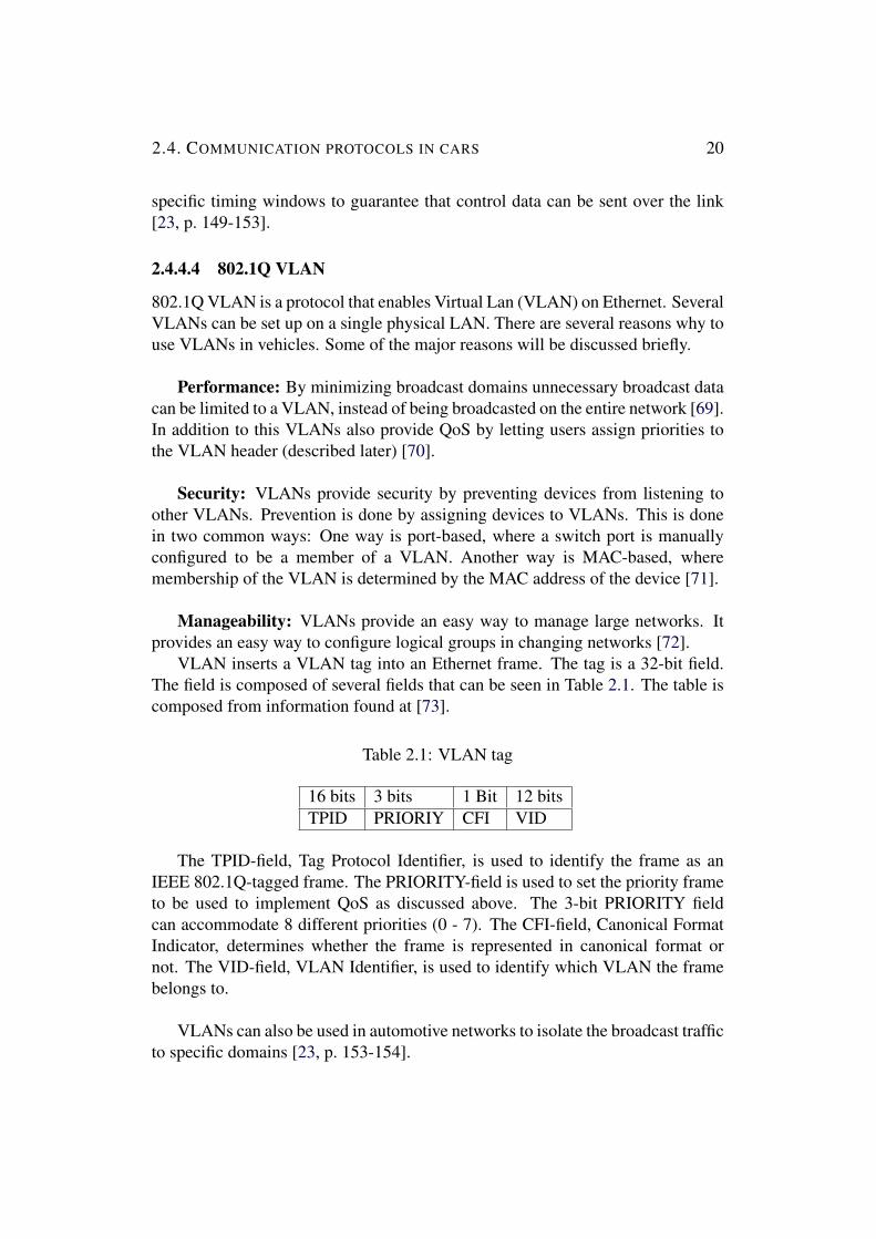
VLAN inserts a VLAN tag into an Ethernet frame. The tag is a 32-bit field.The field is composed of several fields that can be seen in Table 2.1. The table iscomposed from information found at [73].
Table 2.1: VLAN tag
16 bits 3 bits 1 Bit 12 bitsTPID PRIORIY CFI VID
The TPID-field, Tag Protocol Identifier, is used to identify the frame as anIEEE 802.1Q-tagged frame. The PRIORITY-field is used to set the priority frameto be used to implement QoS as discussed above. The 3-bit PRIORITY fieldcan accommodate 8 different priorities (0 - 7). The CFI-field, Canonical FormatIndicator, determines whether the frame is represented in canonical format ornot. The VID-field, VLAN Identifier, is used to identify which VLAN the framebelongs to.
VLANs can also be used in automotive networks to isolate the broadcast trafficto specific domains [23, p. 153-154].

2.5. THE REAL-TIME CONCEPT 21
2.5 The real-time conceptThis section will briefly discuss the concept of real-time. Real-time can meandifferent things depending on the context. When talking about real-time incomputer science one refers to meeting deadlines and making the system behavein a predictable manner. Real-time systems tasks can be divided into threecategories. Tasks that can tolerate some missed deadlines without causing seriousdamage are called Soft Real-time tasks. A task that if it misses its deadline anddoes not cause serious damage but makes the results useless, is called a firm task.A task is called hard if missing the deadline will cause catastrophic consequences[74].There are a lot of concepts that is important to Real-time theory, to evaluatereal-time performance. The list below introduces some terms related to real-timetheory [75, p. 257-259].
• Deadline: The deadline a time that a task has to finish before.
• Latency: The time it takes between when something should happen andwhen it actually does happen.
• Jitter: The variance of the latency.
• Predictablilty: Knowing in advance how long time an operation will take
• Worst case: The worst possible execution time
• Priority Inversion: When a lower priority task is blocking a higher prioritytask from running.
• Periodic task: A task that runs at regular intervals.
2.6 Operating systemsThis section will present commonly used operating systems in automotivevehicles. Additionally this section will describe a choice becoming more popularin the embedded world, well suited for prototyping - Embedded Linux.
There are different subsystems in cars, and therefore different types ofoperating systems are used. One system used in cars is infotainment systems, thatconsists of tasks with soft real-time constraints. There are three major operatingsystems when it comes to infotainment [76]:
• QNX

2.6. OPERATING SYSTEMS 22
• Microsoft Embedded Windows
• Different versions of Linux
QNX is said to have over 50% of the market share, Windows roughly 20%. Linuxis rapidly growing and is to grow continuously [76].
QNX is a UNIX-based RTOS intended for the embedded systems market. Theproduct development started back in the 1980s and the company was bought byBlackBerry in 2010 [77].Microsoft Embedded windows has different families, targeting different embeddeddevices. Windows Embedded Automotive is one embedded operating systemtargeted towards embedded systems, in particular the automotive industry [78][79].An example of an infotainment Linux operating system is Automotive gradeLinux [80].
Patrick Shelly from Mentor Graphics Corporation describes in one of hispresentations the current trends of OS in cars. The presentation presents a numberof different operating systems used for cars, and he mentions the use of Linuxwhen prototyping for ADAS. He states that the trend for under hood electronicsand ADAS is moving towards systems following the Autosar standard.
2.6.1 AUTOSARAUTomotive Open System ARchitecture (AUTOSAR) is a standard developedby a number of partners and the organization was founded in 2003. Amongthe partners are several of the leading automotive companies including BMW,Volkswagen, Ford, Toyota, Genaral Motors and more [81].AUTOSAR provides a number of concepts and architectural specifications. Onething included is the ECU Software Architecture. The architecture is divided inthree different layers [82]:
• AUTOSAR Software
• AUTOSAR Runtime Environment
• AUTOSAR Basic software
AUTOSAR provides a good overview of the layers that can be seen in Figure 2.5.The AUTOSAR software layer consists of AUTOSAR Software Components.
The software components are self contained units of software [83].The AUTOSAR Runtime Environment is middle ware that provides a communicationabstraction to the AUTOSAR Software Components. The middleware allows theSoftware Components to communicate to other ECUs as well as services provided
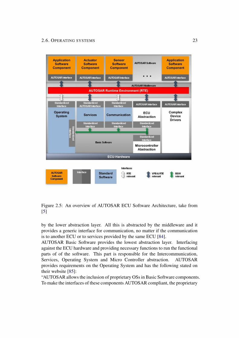
2.6. OPERATING SYSTEMS 23
Figure 2.5: An overview of AUTOSAR ECU Software Architecture, take from[5]
by the lower abstraction layer. All this is abstracted by the middleware and itprovides a generic interface for communication, no matter if the communicationis to another ECU or to services provided by the same ECU [84].AUTOSAR Basic Software provides the lowest abstraction layer. Interfacingagainst the ECU hardware and providing necessary functions to run the functionalparts of of the software. This part is responsible for the Intercommunication,Services, Operating System and Micro Controller abstraction. AUTOSARprovides requirements on the Operating System and has the following stated ontheir website [85]:“AUTOSAR allows the inclusion of proprietary OSs in Basic Software components.To make the interfaces of these components AUTOSAR compliant, the proprietary

2.6. OPERATING SYSTEMS 24
OS must be abstracted to an AUTOSAR OS. The standard OSEK OS (ISO 17356-3) is used as the basis for the AUTOSAR OS. ”
2.6.2 Embedded LinuxThere is no specific OS called Embedded Linux, when talking about EmbeddedLinux it is referred as mainline Linux applied to an Embedded system [86,Chapter 3]. Linux is originally developed as a GPOS but it has grown intobecoming much more than that, due to the large community and its demands.An important feature that has been developed during the past years is the LinuxScheduler. The default scheduler used in a desktop system is the Completely FairScheduler, it divides the processing time evenly among the processes. Anotherscheduler available, besides the default Linux scheduler, is the Linux Real-timeScheduler. To understand what the real-time scheduler is and why it is neededit is important to understand and define what real-time is, this was explained inChapter 2.5.
2.6.2.1 Linux Real-time Scheduler
Running the default scheduler is not optimal in terms of real-time, it is not made tohandle hard or even soft real-time tasks. However, the Linux real-time schedulerenables higher priority tasks to take over execution from lower priority tasks. Thescheduler has two different policies: FIFO and RR. FIFO is a simple scheduler,when a task with higher priority becomes available it will take over execution fromthe lower priority tasks. RR is a similar scheduling policy with one difference:tasks always runs for a specific period of time before being put at the back ofthe line. Even the Linux real-time scheduler is not made to handle hard real-timetasks, as it is impossible to guarantee deadlines and worst case response times [75,Chapter 12].
2.6.2.2 PREEMPT RT Patch
CONFIG PREEMPT RT is the current project developing Linux into a real-timesystem. One part in turning the Linux system suitable for real-time is making itmore preemptible. The PREEMPT RT patch turns Linux into a fully premptiblekernel, allowing even the kernel threads to be preempted [87].The patch also provides the kernel with a real-time scheduler. It balances tasksacross CPUs while still taking real-time tasks in consideration - in contrary to thestandard Linux scheduler. The real-time scheduler uses a push-pull strategy tohandle scheduling tasks with different priority level [88].

2.7. RELATED WORK 25
2.7 Related workThe MOPED platform is a platform developed as a research and educationalplatform for Cyber-Physical Systems. The platform targets automotive systemsand provides an architecture containing both software and hardware. The platformis running on a scale 1:10 model car equipped with actuators and sensors. Theplatform has multiple ECUs connected through an Ethernet hub. Parts of thispaper is reused for this thesis. Similar parts of the model car has been used in thedevelopment of the platform presented in this thesis [89].

Chapter 3
Hardware and software tools
There are several hardware related components used in the realization of thisthesis. In addition to the hardware multiple software tools have been usedthroughout the work process. This chapter will start by introducing the hardwarethat has been used. Followed by the Operating Systems used on the ECUs. Thelast part of this chapter describes the software tools.
3.1 HardwareThis section will present the hardware used in this thesis. Each hardwarecomponent will be discussed in detail. Why it was chosen and how it is usedin the architecture of the platform will be discussed in the next chapter, Chapter 4.
3.1.1 BeagleBone BlackThe BeagleBone Black is one type of ECU used in the platform. It is a credit cardsized one card computer and development platform. An image of the BeagleBoneBlack can be seen in Figure 3.1.
The board is developed by the BeagleBoard.org foundation and is a non-profitorganization settled in the US, which provides open source hardware as well asopen source software. The foundation hosts a community driven support forum,where users can discuss and provide solutions to problems related to the platforms.
All the hardware on the BeagleBone Black is open source as well as all thesoftware available to the users. The SoC of the platform is a Sitara AM3358chipset from Texas Instrument [90].
26

3.1. HARDWARE 27
Figure 3.1: The BeagleBone Black board, taken from [6]
3.1.1.1 Sitara AM3358 chipset
The main processing unit on the chip is a single core ARM Cortex-A8 microprocessor.The microprocessor is a superscalar processor with a RISC architecture. It canissue two instructions per clock cycle with a deep pipeline. The clock is rated at 1GHz but can be scaled up to 1.35 GHz and scaled down to 300 MHz to save power.The microprocessor has a 32KB L1 instruction cache and 32KB data cache. It hasa 256 KB L2 cache with error correcting code. It also has 176KB of On-ChipBoot ROM and 64 KB of On-Chip dedicated RAM. There is a JTAG interface onthe chip, which makes it possible to interact with and debug the core at run time.The chipset also comes with an SIMD co-processor. The co-processor is an ArmNEON general purpose SIMD processor to help with signal processing algorithmsto enhance the encoding and decoding of multimedia.
The main memory is a DDR3 memory with a total of 1GB address space andit is clocked at 800 MHz. The memory has a 16 bit wide data bus.
To help with real time tasks the chipset has a Real-Time clock with an internal32 KHz oscillator. The oscillator can be used to generate internal interrupts.
There are multiple peripherals on the chip. It comes with USB 2.0 ports,Industrial Gigabit Ethernet MACs, CAN ports, Multichannel serial audio ports,UART interfaces, SPI serial interfaces, IX2C interfaces, Interface for 8-bit MMCand SD memory, access to general purpose I/O pins, multiple general purposetimer and a watchdog timer, an LCD controller, ECAP modules to help generatePWM outputs.
Additionally the AM3358 chipset has two on-chip micro controllers. Thetwo micro controllers are inside a subsystem called the Programmable Real-Time

3.1. HARDWARE 28
Unit Subsystem and Industrial Communication SubSystem (PRU-ICSS), and eachmicro controller is called Programmable Real-Time Unit (PRU) [91].
3.1.1.1.1 Programmable Real time Unit
The two PRUs on the chip are clocked at 200 MHz and they are two identicalmicrocontrollers. The microcontrollers have a RISC architecture with no pipeline,IE it can only issue and execute one instruction per clock cycle. Each PRU has8KB of instruction RAM and 8KB of data RAM each memory with Single-errordetection. The two PRUs also has a 12 KB shared RAM memory. The PRU hasaccess to a local interconnect bus to connect to the peripherals inside the PRU-ICSS.The peripherals inside the PRU-ICSS is one UART port, one eCAP module,two Ethernet ports that support Industrial Ethernet and one Management DataInput/Output (MDIO) port.
To grant the PRUs access the rest of the system they have an interruptcontroller to handle system events. It handles interrupts such as interrupts fromthe ARM core, interrupts from peripherals or interrupts from the other PRU.
The PRUs can access and change the state of an output pin in one clock cycle.To load the code onto the the PRU the code has to be transferred onto the PRUfrom the ARM environment. This is done through Linux device drivers [91].
3.1.1.1.2 Programming the Programmable Real Time Unit
To program the PRU a set of steps need to be taken. The code to be run on the PRUhas to be loaded from the ARM environment. This process includes a set of Linuxdrivers and a specific compiler targeting the PRU architecture. The compiler usedto compile the source files into the binaries will be described in the Software toolsChapter 3.3.5.
The Linux driver that handles the PRU to ARM communication is the LinuxRemoteproc driver. This driver is a Linux core driver run in kernel space and itprovides an API for the specific PRU kernel modules. The kernel PRU modulesare called pruss module and pru rproc module, which are loaded from user spaceas any Linux module, using the Linux tool ”insmod”.
The specific software binaries to be run on the PRU are placed in /lib/firmwarewith the specific names; am335x-pru0-fw and am335x-pru1-fw. The modulepru rproc looks in the folder for the two specific files. In each binary file themodule looks for sections describing the resources and allocates the resources.

3.1. HARDWARE 29
The module also creates VRINGS in the DDR memory [92]. VRINGS will bedescribed later in 3.1.1.1.3.
The next step is for the pru rproc driver to load the binaries on to the PRUprogram memory as well as giving it instructions about the resources. The laststep for the pru rproc is to give the PRUs instructions to begin execution. TexasInstrument provides a good overview picture describing this. It can be seen inFigure 3.2.
Figure 3.2: Programming the PRU, image taken from [7]
3.1.1.1.3 Communication between ARM and PRU
The PRU is a separate system on the same chip as the ARM core and it is necessaryfor the two to be able to communicate. The communication between the twosystems is implemented using shared memory. There are several functions andpieces of software connected to passing messages between the systems.
The mechanism used to pass messages is called RPMsg. RPMsg communicateswith the shared memory that is in the DDR memory of the ARM core. There arefour virtual memory areas to allow communication between the systems. Theseareas are specific memory structures called VRINGS and are divided in two parts:used buffers and available buffers. The four VRINGS are divided as follows: twofor each PRU, each PRU has one VRING for host and one for the slave (PRU)

3.1. HARDWARE 30
[92].
If the ARM sends a message to the PRU it takes a used buffer, fills it with dataand puts it in the available buffers. The PRU then reads the data in the availablebuffers and moves the emptied buffer in to the used buffers again [92].
In the case where the PRU sends the ARM a message it takes a buffer from theavailable buffer, fills it with data and then places it in the used buffers. The ARMtakes the buffer from the used buffers, reads the data and places it in the availablebuffers [92].
In order for the systems to know that new messages are available in theVRINGS there is a mechanism implemented called mailboxes. The mailboxesworks as interrupts between the systems. If one system wants to send the othersystem new data it notifies the mailbox, which in its turn will ”kick” the othersystem, to let it know that there is an incoming message [92].
There is a module used in kernel space that communicates with the RPMsgmechanism that allows for user space communication. The module is calledrpmsg pru and it communicates to user space using a character device. If theuser wants to send a message to the PRU it writes to the character device. Thecharacter device file can be read to get messages from the PRU [92]. Again,Texas Instrument provides an overview of how the message passing works, thiscan be seen in Figure 3.3.
3.1.2 PeripheralsThere are 65 GPIO pins available on the BeagleBone Black. The board is suppliedwith 5 Volts but all the GPIO pins operate on 3.3 Volts. Seven of the pins can beused as an ADC with a voltage limit of 1.6 Volts. It has access to an SPI controlleras well as an I2C controller. The board has a CAN controller that can be accessedthrough an expansion connector. It is possible also to access four timers and fourserial ports through the I/O pins. The Beaglebone Black comes with an SD/MMCConnector that supports microSD cards. It is possible to connect a display throughthe miniHDMI port. To connect external peripherals there is two USB ports andone miniUSB port to power and communicate to the board. The Table belowshows the BeagleBone Black specification [93].

3.1. HARDWARE 31
Figure 3.3: PRU-ARM message passing, taken from [8]
Table 3.1: BeagleBone Black hardware specification
Hardware IdentifierCPU AM335x 1GHz ARM® Cortex-A8GPU SGX530 3D, 20M Polygons/SDRAM 512MB DDR3 RAMOnboard Flash 4GB 8-bit eMMCSD/MMC Connector MicroSD 3.3VVideo Out HDMIAudio Via HDMI, StereoEthernet 10/100, RJ45Expansion connectors McASP0, SPI1, I2C, GPIO (69
max), LCD, GPMC, MMC1,MMC2, 7 AIN, 4 timers, 4 serialports, CAN0, EHRPWM(0,2),XDMA Interrupt, Power Button,Expansion Board ID
PRU 2x PRU 32-bit microcontrollers @200 MHz

3.1. HARDWARE 32
3.1.3 Device TreeEmbedded Linux on the BeagleBone does not use a bios to boot and configurethe device. Instead it uses files on the eMMC or an inserted SD card to set upthe system. Previous distributions of Embedded Linux on the BeagleBone hadspecific code inside the Linux kernel to handle the specific device, but this meanthaving lots of extra code added to mainline Linux. Instead of using source codefiles to setup the devices newer ARM boards and kernels use Flattened DeviceTrees.
Flattened Device Trees is a data structure to describe the hardware of thesystem. To change the hardware set up a device source tree file has to be compiledand put it in a specific directory. In order for the changes to take effect the devicehas to be rebooted.
A big drawback with this setup is the need to reboot after each change whichmakes run time configuration difficult [86, Chapter 6].
Fortunately this drawback has been solved by using something called DeviceTree Overlays along with a tool called CapeManager. A utility that does thisautomatically will be described later, in Chapter 3.3.3.
3.1.4 Serial to USB interface - SparkFun FTDI Basic BreakoutA serial to USB interface is used to communicate to the BeagleBone Black’s ARMcore on the serial pins. The device converts the serial data from the pins to serialdata on the USB port.It is sometimes needed to access these pins when compiling and testing differentkernels of the BBB. The serial pins allow the user to get the output of the kernelwithout having access to SSH or other means of communicating with the kernel.The converter used is a SparkFun FTDI Basic Breakout, it uses 6 pins and providesa miniUSB inteface to hook it up to a computer [94].
3.1.5 Raspberry Pi 3 model BOne of the ECUs used in the platform is the Raspberry Pi 3 Model B and is thethird generation of Raspberry Pi. Figure 3.4 provides an image of the RaspberryPi 3 Model B board.
Its performance has increased drastically over the years, while keeping itssmall size and low price. The newest generation has a quad core 1.2 GHz 64-bit ARMv8 CPU and it has built in WiFi. It also has support for Bluetooth 4.1and BLE. On top of the powerful ARM-core it also has a dedicated 3D graphics

3.1. HARDWARE 33
Figure 3.4: The Raspberry Pi 3 Model B board, taken from [9]
core. There is 40 available GPIO pins as well as dedicated ports for a camera anddisplay. The table below lists the Raspberry Pi 3 Model B specification [95].
Table 3.2: Raspberry Pi 3 Model B hardware specification
Hardware IdentifierCPU 4× ARM Cortex-A53, 1.2GHzGPU Broadcom VideoCore IVDRAM 1GB LPDDR2 (900 MHz)Storage microSDVideo Out HDMIAudio 3.5mm analogue audio-video jackNetworking 10/100 Ethernet, 2.4GHz 802.11n
wirelessPorts 4× USB 2.0, Ethernet, Camera
Serial Interface (CSI), DisplaySerial Interface (DSI)
3.1.5.1 RPI dedicated camera
The Raspberry Pi 3 Model B has a built in connector for a dedicated camera. Thecamera used is The Raspberry Pi Camera Module v2, seen in Figure 3.5.

3.1. HARDWARE 34
Figure 3.5: The Raspberry Pi Camera Module v2, taken from [10]
The camera can capture video 1080p in 30 FPS or 720p in 60 FPS. The camerasensor is a Sony IMX219 8-megapixel sensor [96].

3.1. HARDWARE 35
3.1.6 TP-link TL-SG105E Network SwitchTo allow the ECUs to communicate with each other a network switch is used.This section will describe the network switch used in this project. The TP-linkTL-SG105E is a five port network switch. An image of the actual switch can beseen in Figure 3.6.
Figure 3.6: The TP-link TL-SG105E network switch, taken from [11]
Each port is an RJ45 port support 10/100/1000 Mbps. The switch supportsnetwork monitoring, traffic prioritization, QoS and VLANs. The switch ismanaged through a web-based user interface. It supports Ethernet standardssuch as 801.2p and 801.2q. The switch also has features to prevent loops in thenetwork. The switch has multiple options to enable QoS. One way is to to port-based QoS where each port can be assigned four different priorities and the switchwill move all packets of the port to the according priority queue. Another way ofimplementing QoS is the 801.2P based solution. The switch with a set up VLANwill look at each 801.2Q frame and assign a priority to the packet, based on thepriority found in the frame. Below is the priority assignments described [97]:
• Priority 1 and 2 are assigned to the 1 (Lowest) priority queue.
• Priority 0 and 3 are assigned to the 2 (Normal) priority queue.
• Priority 4 and 5 are assigned to the 3 (Medium) priority queue.
• Priority 6 and 7 are assigned to the 4 (Highest) priority queue
It is not stated by TP-link why the priorities are not assigned continuous.Below, in Table 3.3, is a table which explains each priority level defined in the802.1D standard [98].
Another important feature, as mentioned earlier, of the TP link switch is thefunction that enables loop prevention. The loop protection blocks the port if aloop is detected [97]. It is not explicitly stated which protocol it uses to preventloops. Most likely it uses SPT, described in Chapter 2.4.4.2, or SBTV, describedin the same chapter, since it states that it blocks the port.

3.1. HARDWARE 36
Table 3.3: Priorities according to traffic typeValue Traffic type0 Best Effort1 Background2 Spare3 Excellent Effort4 Controlled load5 Video6 Voice7 Network control
3.1.7 Model CarThe model car is built from several different components put together to mimica real car. The chassis of the car is a Turnigy SCT 2WD 1/10 Brushless ShortCourse Truck (KIT) upgraded version, is a 1:10 scale car with a length of 530 mmand a width (between the wheels) of 330 mm. The chassis of the model car canbe seen in Figure 3.7.
Figure 3.7: Turnigy SCT 2WD 1/10 Brushless Short Course Truck (KIT)upgraded version, taken from [12]
The steering servo, to turn the wheels, is a HobbyKing™ High Torque AnalogServo Waterproof 4.5kg / 0.13sec / 40g. The torque of the servo is 4 kg.cm and itsturn rate is 0.16sec/60deg. How a servo is controlled is described in 3.1.7.1. Themotor in the car is a Turnigy TrackStar 17.5T Sensored Brushless Motor 2270KV.It is a sensored brushless motor rated at 2270kv. To run the brushless motora specific controller is needed, called Electronic Speed Controller (ESC). TheESC used in the model car is a HobbyKing® ™ X-Car 45A Brushless Car ESC(sensored/sensorless), can supply a coninous current of 45A and is compatible

3.1. HARDWARE 37
with sensored brushless motors. How a brushless motor and an ESC work isdescribed further in Chapter 3.1.7.3To supply the car with power a ZIPPY 4000mAh 2S1P 30C Hardcase Pack batteryis used. It is a 2-cell LiPo battery with a high discharge rate. To supply the onboard electronics with low volt power the car needs a voltage regulator. Thevoltage regulator used is a TURNIGY 8-15A UBEC for Lipoly it can supplyboth five and six volts channels each with a maximum draw of eight ampereson each channel. The car also needs special devices for charging the LiPo batteryand for tuning the ESC. To charge the battery a Turnigy Accucell-6 50W 6ABalancer/Charger LiHV Capable is used and for tuning and configuring the ESCa HobbyKing® ™ X-Car Beast series LCD Program Card is used.The table below, Table 3.4, gives a summary of the components used to build themodel car.
Table 3.4: Components used to build the model car
Description ComponentCar chassis Turnigy SCT 2WD 1/10 Brushless
Short Course Truck (KIT) upgradedversion
Steering servo HobbyKing™ High Torque AnalogServo Waterproof 4.5kg / 0.13sec /40g
Motor Turnigy TrackStar 17.5T SensoredBrushless Motor 2270KV
ESC HobbyKing® ™ X-Car45A Brushless Car ESC(sensored/sensorless)
Battery ZIPPY 4000mAh 2S1P 30CHardcase Pack
Voltage regulator TURNIGY 8-15A UBEC forLipoly
Battery Charger Turnigy Accucell-6 50W 6ABalancer/Charger LiHV Capable
ESC programmer HobbyKing® ™ X-Car Beast seriesLCD Program Card

3.1. HARDWARE 38
3.1.7.1 Servo motor
A servo motor is a motor that when given a PWM pulse will move to a specificangle based on the shape of the pulse. The angle usually goes from 0 to 180degrees. A servo is in most cases controlled using a PWM signal. There are twoimportant factors when talking about PWM signals: the pulse width and the dutycycle. The pulse width is the width of the pulse and the duty cycle is the timecycle from the start of one pulse to the start of the next pulse.
Normally the duty cycle, when talking about servo control, is set to 20milliseconds. The width of the pulse defines the angle, the common case is that awidth of 1.5 milliseconds sets the motor at 90 degrees, 1 millisecond at 0 degreesand 2 milliseconds sets it at 180 degrees. Figure 3.8 shows an image describinghow the PWM pulse works and how it controls a servo.
Figure 3.8: Controlling a servo motor
3.1.7.2 Brushless motor
To understand how a brushless motor works it is easiest to compare it to a normalbrushed DC motor. In a normal brushed DC motor the coil is surrounded bymagnets and the coil changes the direction of the current to rotate. A brushlessmotor on the other hand have multiple coils and rotates by changing which ofthe coils have current running through them. This is controlled with a specificcontroller or in specific software [99].

3.1. HARDWARE 39
3.1.7.3 ESC
Since the brushless motor can not be powered by applying DC-current a specificcontroller is needed. One way of controlling a brushless motor is using anElectronic Speed Controller (ESC). An ESC is essentially a driver circuit to drivethe motor. ESC driving brushless motors normally takes a servo pulse as the input,and outputs power to the motor over a three-wire interface [100].
3.1.8 Android deviceAn android device is used to control and steer the car. It is connected through WiFito the Raspberry Pi. The Application running on the device will be described indetail in the next chapter. Android is a mobile operating system that is developedby Google. The operating system is based on a Linux kernel and it is mainlydesigned to target mobile devices such as phones and tablets [101]. The androiddevices used in this thesis is both emulated devices supplied by Android studio(discussed in Chapter 3.3.2) and a One Plus One mobile phone, running android6.0.
3.1.9 SensorsThe model car is equipped with multiple sensors, in addition to the camera alreadydescribed.
3.1.9.1 Ultra Sonic Sensor, HC-SR04
The HC-SR04 is a distance sensor using ultra sonic waves to detect objects. Itsupports detecting objects in a range from 2 cm up to 400 cm, with a resolution of0.3 cm. Figure 3.9 shows an image of the sensor used.
It is recommended to send pulses to the sensor in a frequency lower than 40Hertz, in order for the echo pulse to settle. The sensors automatically handlesundetected pulses. If a pulse is too long or never comes the sensor will end thepulse equal four meters. The sound is spread in a cone with an angle of 30 degrees.The user has to send a pulse to the sensor that is 10 microseconds long. Thesensors reacts to the 10 microsecond pulse and sends an 8 cycle burst at 40 kHz.An incoming pulse equal to the time the pulse traveled will be output from thesensor. The user has to interpret the pulse and measure it in order to get thedistance.
The sensor has four pins, one pin to trigger the pulse called TRIG, one pinto read the echo called ECHO, one pin to supply Vdd and one ground pin. The

3.2. OPERATING SYSTEM 40
Figure 3.9: The HC-SR04 is a distance sensor, taken from [13]
supply voltage is five volts, which is the same voltage level as the logic of thesensor. The HC-SR04 is a transceiver, it can both receive and send pulses. Themodule also has a built in controller and the distance is interpreted as a pulse. Thelength of the pulse determines the distance [102].
3.1.9.2 Reflective sensor, OPB715Z OPTO SWITCH
OPB715Z OPTO SWITCH, is used to determine the speed of the car. The sensormeasures IR light reflections. It constantly emits IR light and checks for anincoming reflection from the light. As the sensor receives the light it sends outa high pulse that can be captured using a controller. The sensor can be run at fivevolts and will then generate a five volt output [103].
3.1.9.3 Motion sensor, MPU-9250
The MPU-9250 is a nine-axis motion sensor. The sensor has a three-axisgyroscope, a three-axis accelerometer and a three-axis magnometer. The sensoris interfaced using I2C protocol and data can be fetched as digital data. Thegyroscope detects differences in angles; the accelerometer measures the relativeposition in XYZ to earths gravity and the magnometer can act as a compass [104].
3.2 Operating SystemThis section will describe the Operating System run on the ECUs. There aremultiple OS available for cars. Some of the most popular ones have already beendiscussed in Chapter 2.6. This platform uses non of these, but a distribution of

3.2. OPERATING SYSTEM 41
Linux with a real time kernel configured. The reasoning why this OS was thechoice will be further discussed in Chapter 4.
3.2.1 Linux 4.4-ti-rtThe operating system that is run on the BeagleBone Black is Linux. The kernelis a 4.4 Linux kernel with the PREEMPT RT patch applied. More specifically itis the 4.4.19-ti-rt-r41. The kernel is a kernel modified by Texas Instrument, themanufacturer of the SoC of the BeagleBone Black. The reason why Linux waschosen as the Operating System is discussed in Chapter 4.2.It is important to know what networking scheduling policy the Kernel is using.The 4.4.19-ti-rt-r41 kernel uses pfifo fast scheduling policy, as can be seen inFigure 3.10. pfifo fast is the default network queueing policy. The policy providesthree different FIFO queues to separate the traffic. Packets with highest priorityare allways placed in FIFO 0 and is always served first. FIFO 1 is always servedbefore FIFO 2 [105].
Figure 3.10: pfifo fast queuing policy, taken from [14].
3.2.2 Linux 4.4-rtThe operating system run on the Raspberry Pi 3 Model B is a linux based operatingsystem with the PREEMPT RT patch applied. The kernel is, similar to the one

3.3. SOFTWARE TOOLS 42
running on the BeagleBone Black, a Linux 4.4 kernel. More specifically it runs4.4.9-rt17. The kernel also has the same networking scheduling policy as theLinux 4.4-ti-rt kernel, used for the BeagleBone ECUs.
3.3 Software toolsThis section will describe the software tools used throughout the project. Thereare multiple tools used, each tool will be described and a description of why it isneeded will be provided.
3.3.1 WiresharkWireshark is a network protocol analyzer. Wireshark lets the user both capturepackages live and create recordings. It is possible to create filters to only inspectcertain packets or protocols [106].
The tool is used to inspect and debug the traffic sent over the internal networkof the system. It is possible to inspect packets at different abstraction level, whichmakes it possible to see the VLAN tags and VLAN priority fields. It is also usedto inspect the traffic being sent over the WiFi from the RPI ECU.
3.3.2 Android studioAndroid studio is the most widely used tool to develop Android applications. It isa GUI based tool, with a powerful debugger. It is also possible to run an Androidemulator though Android studio, emulating a wide selection of different targetdevices.
3.3.3 config-pinThe config-pin utility helps to configure the output pins by using the devicetreeoverlays and capemanager. It is possible through a simple command, with the pinID as the parameter, to configure a pin for a specific task. Listing 5.2 shows anexample use of the config-pin utility.
Listing 3.1: Config-pin example
c o n f i g−p i n −a P8 45 p r u o u tc o n f i g−p i n −q P8 45

3.3. SOFTWARE TOOLS 43
c o n f i g−p i n −a P8 46 p r u i nc o n f i g−p i n −q $P8 46
The example above sets pin 45 on header P8 to be an output connected to thePRU subsystem and pin 46 on header P8 to be an input to the PRU.
3.3.4 CyclictestCyclictest is a benchmarking software used to test real-time performance of anoperating system. Essentially it measures the latency of a response to a stimulus.The system can be tested running the operating under different loads [107].
3.3.5 TI PRU C compilerTo program the PRU the TI PRU C compiler is used. It is necessary to use aspecific compiler for the PRU that is targeting the specific architecture of thePRU. There are other compilers available, but this is the one supported by TexasInstruments, the manufacturer of the BeagleBone Black SoC. The compiler isalso included in CCS, a development environment from Texas Instruments, but itis possible to run it outside the environment [108].
At the early stages of the PRU development there was no C compiler, insteadassembly was the only way to program the PRU. At present time, there is C librarycode to access most of the registers and functionality exposed to the PRU, howeverthe documentation is lacking in detail. It is necessary to look through the librarycode in order to fully understand how to use all available C functions.
3.3.6 Device Tree CompilerWhen working with the BeagleBone black device trees and device tree overlaysare needed to configure and set up the hardware and peripherals. The device treecompiler takes device tree source file and compiles it in to device tree binaries.What device trees are and what they are used for was previously discussed inChapter 3.1.3.

Chapter 4
Design
This chapter will describe the design of the platform. The design is a major part ofthe results of this thesis and one of the core goals. The chapter starts by discussingthe hardware chosen for the project in terms of why the specific hardware waschosen. The next part discusses the operating systems used. The last part of thischapter provides an overview of the system architecture.
4.1 HardwareThere are a lot of hardware components described in the previous chapter. Allof the hardware has been chosen for specific reasons. This section will discussthe design of the platform and the reasoning to why the specific design waschosen. More specifically this section will describe the hardware related partsof the design.The first hardware to discuss is the ECUs that are part of the platform. Thenext step to discuss is the choice of network switches. Furthermore the choiceof sensors are discussed, followed by a discussion regarding the choice of modelcar, actuators and electronics. The last piece of hardware to be discussed is theandroid device.
4.1.1 ECUsThe platform is equipped with two different types of ECUs, the BeagleBone Blackand the Raspberry Pi 3 Model B. The BeagleBone Black was chosen due to itsability to handle real-time tasks with the help of the on-chip PRUs. Without havingthese real-time units the use of sensors that require exact timing on the output pinswould become a difficult task. The PRUs also enable for further implementationof specific protocols by programming the PRUs to act as controllers. Additionally
44
4.1. HARDWARE 45
the BeagleBone Black has the capability of running as an AVB device. This is,however, not possible yet, as it would require additional work before it can beavailable. This will be discussed further in Chapter 6.2. Another reason why touse the BeagleBone is that the hardware is Open Source.
Initially the plan was to only use BeagleBone Blacks as ECUs but there wasa need for a wireless interface. This could be done by adding a USB wirelessnetwork interface to one of the BeagleBone Blacks, but it would cost almost asmuch as adding another ECU that already has WiFi capabilities. Additionally,the BeagleBone Blacks are not very good at handling heavy parallel tasks suchas image processing. This would limit the ability of the platform because one ofthe important sensors, being part of ADAS, are cameras. The RPI 3 Model B hasboth WiFi and, due to its relatively sophisticated GPU, the ability to do imageprocessing. Also, there is a lot of information related to image processing, such asobject detection and image recognition, available by the Raspberry Pi community.
Both of the two ECUs are running on an ARM main processing unit, whichis a common choice for automotive ECUs, as was discussed in Chapter 2.1. TheBeagleBone also has access to an on-chip microcontroller (the PRU), running aRISC core, which is also a popular choice in the automotive industry.
4.1.2 Network switchesThe network switches used are the TP-link TL-SG105E Network Switches,described in detail in Chapter 3.1.6. They are cheap and they support the 802.1QVLAN standard. It is important for the switches to support real-time Ethernetfeatures. VLANs can also be used for automotive purposes to limit broadcasttraffic in automotive Ethernet networks, see Chapter 2.4.4.4.There are switches that have full AVB/TSN support and can provide much betterperformance in terms of real-time. The downside to these switches are that theyare very expensive and complicated to use. Many of these switches that areavailable on the market only support proprietary software to implement the AVBstandard, and it is not possible to integrate them in a project like this. Anothersignificant reason why not to use such switches are that in order to follow theAVB/TSN standard there is a need for specific Ethernet drivers, hardware supportin the end nodes and a software stack. As of today none of this is available for theBeagleBone Black nor the Raspberry Pi 3 Model B.
4.1. HARDWARE 46
4.1.3 SensorsThe sensors used in the project include an ultrasonic sensor that can measure thedistance to objects in front of it, a reflective sensor, a nine-axis IMU and a camera.The ultrasonic sensor is used in a lot of projects available on the internet and thereis a lot of documentation to it. The sensor is also well suited as it can be usedto demonstrate some simple scenarios, as parking assistance, automated breaking.As mentioned in Chapter 2.2 the ultrasonic sensor is commonly used in ADAS,and has been for quite a while.The reflective sensor is used to detect the wheel speed. It is fitted on the wheel axisof the car to point to the inside of the wheel. Inside the wheel there is reflectivetape to generate pulses. By measuring theses pulses it is possible to get the speedof the wheel and the car. This is a similar technique to what the MOPED projectused to acquire the speed of the vehicle.The nine-axis IMU is used in cars to measure dynamically changing movementsof cars. The camera is frequently used in ADAS and is a cheap option toimplement complex functions of ADAS. In addition the RPI Camera module isa well documented camera and the Raspberry Pi community provides a lot ofsupport for various implementations using the camera.
4.1.4 Model car, actuators and electronicsA lot of the parts related to the model car was chosen because they were previouslyused in the MOPED project, described in Chapter 2.7. The author of this thesishas previously worked with the MOPED platform and has insights to what wasworking for the MOPED platform. Some parts of the car were not used in theMOPED project, because these parts were replaced by newer versions.
The chassis of the car is not the same as the one suggested by MOPED, but asimilar one that comes in pieces. The reason why this chassis was chosen insteadof what was used for MOPED is that it is cheaper and it provides more modularity.The motor is the same one as the MOPED project used, it is a high quality motorand it makes it possible to run the car at low speeds. It is important to be able torun the car at low speeds when testing different scenarios. A lot of other brushlessmotors are better suited to run at higher speeds.To steer the car a steering servo is needed. The one MOPED used was included inthe chassis, but the chassis used in this thesis came without one. The servo chosenis a high torque servo, which is necessary to be able to turn the wheels. This wasone of the cheaper high torque servos that was in the correct size to fit the chassis.The ESC is the same one as the one in the MOPED project, and it can be tuned torun the motor at lower speeds using a programming card. The ESC is rated at 45

4.2. CHOICE OF OS 47
amperes and can supply enough power to the motor.The battery powering the car is also the same one as the one used in MOPED. Itis important to have a high discharge rate battery to be able to handle the largeamount of current drawn by the motor. LiPo batteries have high discharge ratesand are well suited to power Radio Controlled cars and projects like this.Another important part is the voltage regulator, described in Chapter 3.1.7. It iscompatible with the battery as it can take the same voltage. The regulator canoutput enough current to run all the electronics running at 5 volts, including allECUs, the servo and the sensors.
4.1.5 Android deviceThe choice of android device is not important as almost any android device canbe used for the purpose of controlling the car. What is more important is thereasoning behind the choice of an Android platform rather than what specificAndroid device to use. The choice to go with an android device is because itis easy to use and it can be hand held. The development environment is easy touse and the author has experience in Java programming and Android development.
4.2 Choice of OSThe operating system chosen is presented in Chapter 3.2. It is a Linux operatingsystem with a real-time patch applied. Linux is, as already stated not initiallyintended to be an RTOS, but a GPOS. However with the real-time patch applied itprovides better performance in terms of real-time. There are other alternatives ofOperating Systems that will perform better and are more suited for real-time andreliability tasks, such as OS implementing the AUTOSAR standard. However,this platform is not intended to be a product that lives will depend on. The pointof the platform is to create a prototype as a proof-of-concept to test different typesand concepts of ADAS. As stated in Chapter 2.6.2 Linux is used for prototypingsystems when it comes to ADAS.The advantage of Linux is that it is widely used, open source and it has a hugecommunity providing support. Linux is also the OS supported by BeagleBoneand RPI. Furthermore, a big advantage for Linux in this specific product is that alot of students is familiar with Linux. Below is a list compiled with the benefitsand drawbacks of using Linux for this platform.
• + Easy to use
• + Large community, support by the BeagleBone and RPI community

4.3. OVERVIEW OF THE SYSTEM ARCHITECTURE 48
• + Provides real-time features
• + OS known to students
• + Good for prototyping
• - Not hard real-time
Moreover, the PRUs on the BeagleBone board give the user possibilities to dohard real-time tasks.
The other alternative, to use an AUTOSAR derivative OS would require a lotmore work, in terms of developing new software, learning the OS and compiling itfor the BeagleBone Black board. It would also increase the amount of time spentfor anyone trying to use the platform. In addition, implementations following theAUTOSAR standard are not open source. Using an AUTOSAR implementationwould limit the availability and the exetendibility of the platform.
4.3 Overview of the system architectureThis section will describe how the hardware is assembled to create the architecture.The platform uses three TP-link TL-SG105E network switches to create thecommunication network of the platform. Each network switch is connected tothe other with a Cat 6 network cable. Each node in the network is connectedthrough a VLAN with a 801.2Q tag, defining the priority of each data stream. Thenetwork topology can be seen in Figure 4.1

4.3. OVERVIEW OF THE SYSTEM ARCHITECTURE 49
Figure 4.1: Network topology
The topology used on the platform is three switches all connected to eachother and the ECUs. The reason why this topology was chosen is because thistopology emulates a real topology that could be used in a real system. It providesredundancy without requiring a large amount of switches. The topology allows forlink faults, while still providing a link between the ECUs. An example is shownin Figure 4.2.
SW2
SW1
SW3
Link1 Link2
Link3
Figure 4.2: Example of broken link
If Link2 is broken and SW1 wants to send a packet to SW3, the packet can

4.3. OVERVIEW OF THE SYSTEM ARCHITECTURE 50
travel SW1 - SW2 - SW3 instead.The system consists of four ECUs, three BeagleBone Blacks and one RaspberryPi. Two of the BeagleBone Blacks read sensor data and propagate it to the thirdBeagleBone Black that controls the actuators. The forth ECU, the Raspberry Pi 3Model B, reads the camera data and handles the external WiFi communication andmonitors the network status. There is also a fifth node connected to the network:an android device. Exactly how the communication works, how the actuatorsare controlled, how the sensor data is read, how the android Application andcommunication works is described in detail in Chapter 5, where it is describedhow the implementations work. Figure 4.3 gives an overview of the systemarchitecture.
RPI with WiFi
BBB3
BBB2
BBB1
SW2
SW3SW1
ESC / motor
AndroidApp
WiFi
Camera
Internal Ethernet VLAN 801.2Q Network
Ultrasonic sensor
RouterWiFi
Steering servo
Reflectivesensor
IMU
Figure 4.3: Overview of the system architecture
The nodes BBB1, BBB2, BBB3 are the BeagleBone Black nodes. TheBBB1 and BBB2 ECUs are connected to the sensors and collect the sensor data.The BBB3 is connected to the actuators of the platform. The RPI with WiFi

4.3. OVERVIEW OF THE SYSTEM ARCHITECTURE 51
block is the Raspberry Pi 3 Model B node. The RPI ECU handles the externalcommunication and the camera sensor. All ECUs are connected together over theinternal network, where SW1, SW2 and SW3 are the Ethernet network switches.
The architecture tries to mimic a real system inside a car, containing multipleECUs, an in car network with multiple network switches, sensors and actuators.The car also provides a wireless connection to the outside world, with the helpof the WiFi interface on the RPI 3 ECU. Due to the multiple ECUs built ontop of the network architecture advanced features of ADAS can be tested, evenfeatures requiring sensor fusion. The flexible underlying architecture also allowsfor extensibility of the platform, where additional ECUs can be added on top ofthe underlying communication architecture. In addition additional sensors can beadded either to the already existing ECUs, or by adding additional ECUs.The wireless interface of the architecture allows the platform to communicatewith external interfaces. This can be used for an external control interface tocontrol the platform. It can also be used to monitor the car from any externalinterface that has an Ethernet interface. In addition a wireless interface allowsthe platform to perform highly advanced functions of ADAS, such as V2I andV2V communication. These features will be further discussed in the the next twochapters.

Chapter 5
Implementations
This chapter will discuss the implementations done for the thesis. Each implementationwill be presented individually. The chapter will start by discussing the implementationthat handles the communication between the ECUs. The next thing that willbe presented is the kernel implementations on the ECUs. Furthermore theimplementation that reads sensor data will be presented, followed by a descriptionof the implementation to control the actuators. The next thing that is presented isan implementation to monitor the car network. Moreover the implementation tocontrol and monitor the car is presented. A way of logging errors on the platformis briefly discussed.
5.1 Car network and ECU to ECU communicationAn important task of this thesis is to create the underlying communication betweenthe ECUs. This section will describe how the network is built and how the ECUscommunicate.
The communication network follows the 802.11Q Ethernet protocol. Theprotocol is set up using VLANs, described in Chapter 2.4.4.4. The VLAN makesit possible to set priorities to traffic flows. The priority can be statically configuredfrom the VLAN script or set for specific data flows. The priority can be set fromC-code using the setsockopt()-function. The function sets the priority field in theVLAN tag for a specific socket. The priority is read in the network switchesand is assigned to the internal priority queues in the switch, as described inChapter 2.4.4.4.Additionally, changing the priority of the socket will also change the priority ofthe network scheduler in Linux. Increasing the priority will send packets withhigher priority according to the policy described in Chapter 3.2.1.
52

5.1. CAR NETWORK AND ECU TO ECU COMMUNICATION 53
The VLAN is automatically configured when the ECU boots. This is doneusing a shell script. The shell script used to set up the VLAN on one of theBeagleBone Blacks is shown in Listing 5.1.
Listing 5.1: Vlan setup script
# ! / b i n / sh# l o c a t e d i n / e t c / i n i t . d / v l a n s e t u p . sh# s e t u p v l a nsudo v c o n f i g add e t h 0 34sudo i f c o n f i g e t h 0 . 3 4 1 9 2 . 1 6 8 . 1 . 2 netmask 2 5 5 . 2 5 5 . 2 5 5 . 0sudo v c o n f i g s e t e g r e s s m a p e t h 0 . 3 4 0 0sudo v c o n f i g s e t e g r e s s m a p e t h 0 . 3 4 1 1sudo v c o n f i g s e t e g r e s s m a p e t h 0 . 3 4 2 2sudo v c o n f i g s e t e g r e s s m a p e t h 0 . 3 4 3 3sudo v c o n f i g s e t e g r e s s m a p e t h 0 . 3 4 4 4sudo v c o n f i g s e t e g r e s s m a p e t h 0 . 3 4 5 5sudo v c o n f i g s e t e g r e s s m a p e t h 0 . 3 4 6 6sudo v c o n f i g s e t e g r e s s m a p e t h 0 . 3 4 7 7
e x i t 0
The script configures the VLAN to be using the eth0 Ethernet interface -the Ethernet interface used on the BeagleBone Black. Next the script tells whatnetwork the VLAN is to be set up on, in this case 192.168.1.2. Lastly the egressmap has to be set up. The egress map tells how the mappings of the priorities ofthe outgoing packets should be arranged. In this case the priorities are mappedto the priority they are set from the context. The map can be used to map presetpriorities from other software to either a lower or a higher priority.
Another important thing to take into account is that, due to the design of thenetwork topology, switching loops can occur. This phenomenon is described inChapter 2.4.4.2. To avoid the problem the switches are configured to avoid loops.This setting is reached from the configuration GUI of the network switch.
Besides the underlying communication layer described above the ECUscommunicate using the transport layer protocol UDP. Each ECU in the networkhas a statically configured IP-address and each of the ECUs know the address ofall the other ECUs in the network. Packets are sent using the static IP-address andby using UDP sockets. All socket software implemented is written in C.

5.2. IMPLEMENTING THE OS 54
5.2 Implementing the OSThis section will describe the process to implement the operating systems runningon the ECUs. Firstly the section will describe the process of deploying the OSrunning on the BeagleBone ECU, followed by a description of how to implementthe OS on the Raspberry Pi ECU.
5.2.1 BeagleBone ECUA big time consumer in this thesis, was to figure out how to compile a stablekernel with the PREEMPT RT patch applied and at the same time enable the PRUenvironment. This proved to be quite difficult as there is no complete guide onhow to do this. This section will describe the procedure on how to do this, foranyone trying to reproduce the OS used in this thesis.
The first step to do is to compile a kernel with the PREEMPT RT patchapplied. This can be done by following a guide supplied by EEWIKI [109]. Theguide gives complete instructions on how to compile a kernel and how to deploydifferent version of Linux file systems on top of the kernel. The process includesinstruction on how to cross-compile the kernel targeting the ARM architecture.
An SD card is needed to complete this guide, and only one card is needed, asthe OS can be moved to the eMMC of the BeagleBone Black. The kernel chosenis the ti-rt-4.4 kernel. This kernel has the real-time patch already applied to it. Theroot file system used is a light version of Debian, namely Debian 8 (small flash).It is important to install the bb-overlays as stated in the guide. There is no needto enable the HDMI, as it will only limit the amount of GPIO pins and there is noneed for a graphical interface. The guide also gives instructions on how to flashthe SD-card to the eMMC of the BeagleBone Black. There is no need to do thisyet as it would only complicate the process. The BeagleBone Black should now beable to boot with the SD-card inserted by holding down the USER/BOOT button.To verify that it is booting from the SD-card, type uname -a in the terminal. Theoutput should list the kernel running.
The next step is to download the dtb-rebuilder to be able to compile the devicetree files. The dtb-rebuilder can be found in this git repository [110]. The dtb-rebuilder is a device tree compiler to compile device tree source files into binaries.
Edit the am335x-boneblack-overlay.dts, the device tree overlay to be used,which can be found in the git repository [110]. Uncomment the line saying#include ”am33xx-pruss-rproc.dtsi” in the .dts file. This enables the pruss-rprocdriver, described in Chapter 3.1.1.1.2. Type make;sudomakeinstall to install the
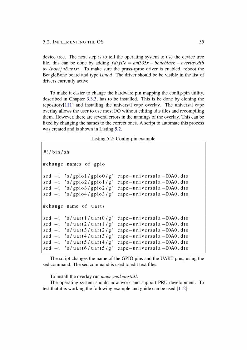
5.2. IMPLEMENTING THE OS 55
device tree. The next step is to tell the operating system to use the device treefile, this can be done by adding f dt f ile = am335x− boneblack− overlay.dtbto /boot/uEnv.txt. To make sure the pruss-rproc driver is enabled, reboot theBeagleBone board and type lsmod. The driver should be be visible in the list ofdrivers currently active.
To make it easier to change the hardware pin mapping the config-pin utility,described in Chapter 3.3.3, has to be installed. This is be done by cloning therepository[111] and installing the universal cape overlay. The universal capeoverlay allows the user to use most I/O without editing .dts files and recompilingthem. However, there are several errors in the namings of the overlay. This can befixed by changing the names to the correct ones. A script to automate this processwas created and is shown in Listing 5.2.
Listing 5.2: Config-pin example
# ! / b i n / sh
# change names o f gp io
sed − i ' s / gp io1 / gp io0 / g ' cape−u n i v e r s a l a −00A0 . d t ssed − i ' s / gp io2 / gp io1 / g ' cape−u n i v e r s a l a −00A0 . d t ssed − i ' s / gp io3 / gp io2 / g ' cape−u n i v e r s a l a −00A0 . d t ssed − i ' s / gp io4 / gp io3 / g ' cape−u n i v e r s a l a −00A0 . d t s
# change name of u a r t s
sed − i ' s / u a r t 1 / u a r t 0 / g ' cape−u n i v e r s a l a −00A0 . d t ssed − i ' s / u a r t 2 / u a r t 1 / g ' cape−u n i v e r s a l a −00A0 . d t ssed − i ' s / u a r t 3 / u a r t 2 / g ' cape−u n i v e r s a l a −00A0 . d t ssed − i ' s / u a r t 4 / u a r t 3 / g ' cape−u n i v e r s a l a −00A0 . d t ssed − i ' s / u a r t 5 / u a r t 4 / g ' cape−u n i v e r s a l a −00A0 . d t ssed − i ' s / u a r t 6 / u a r t 5 / g ' cape−u n i v e r s a l a −00A0 . d t s
The script changes the name of the GPIO pins and the UART pins, using thesed command. The sed command is used to edit text files.
To install the overlay run make;makeinstall.The operating system should now work and support PRU development. To
test that it is working the following example and guide can be used [112].

5.3. SENSORS 56
5.2.2 Raspberry Pi ECUThe kernel used for the Raspberry Pi ECU is a pre-compiled kernel from [113].It is possible to compile the kernel from scratch and apply the preemptive patchmanually, but that would require unnecessary extra work.The simplest way to install the pre-compiled kernel is to first download and installan image from the raspberry pi web page [114]. The image used is the RaspbianJessie Lite. The web page provides instructions on how to deploy such an imageon to an SD-card. After the image is downloaded the kernel can be replaced withthe pre-compiled preemptive kernel. This can be done by following the guide on[115].After the guide is completed the Raspbian Jessie Lite image should be up andrunning with the PREEMPT RT patch applied.
5.3 SensorsThe platform is currently only implementing one sensor, an ultrasonic sensor. Thewheelspeed sensor, the IMU and the camera is as of current not implemented. Thissection will describe how the sensor data from the ultra sonic sensor is acquiredand interpreted.
5.3.1 Ultra Sonic sensorThis section will describe the process to acquire the data from the sensor. To getsensor data it requires software to run both on the ARM core and on one of thePRUs. Figure 5.1 explains the algorithm to retrieve data from the sensor on thePRU, in a graphical way.
In order to get the data from the HC-SR04 ultrasonic sensor a 10 microsecondpulse is generated. The sensor outputs a pulse with the length equal to the time ittakes for the sound to travel to the object and back.The PRU subsystem handles the generation of the pulse as well as interpretingthe incoming response from the sensor. To generate the pulse the PRU sets theoutput pin to zero, waits for 2 microseconds, sets the pin to high, waits for 10microseconds and then sets it back to zero again. This generates a pulse with thewidth of 10 microseconds.The next step is for the PRU to wait for the incoming pulse. To do this thePRU waits for the input pin (the pin connected to the ECHO pin of the sensor)to become high. When the pin becomes high the timer is started and its counter isset to zero. Further the PRU waits until the pin goes back to zero again. When thepin is set to zero the timer is stopped and its value is acquired. The value collected

5.3. SENSORS 57
Figure 5.1: Ultrasonic sensor algorithm
(the number of cycles that has passed) is then converted in to microseconds byusing the following formula:
microseconds = cycles∗ 106
clock f requency(5.1)
Where microseconds is the width of the pulse received, cycles the number ofcycles in the timer register, 106 is to scale it to microseconds and the clockfrequency is the clock frequency of the PRU (200 MHz). Next, the microsecondsis converted to a distance in millimeters, by using the following formula:

5.3. SENSORS 58
distance = microseconds∗ 10005882
(5.2)
Where distance is the distance to the object in millimeters; microseconds is thewidth of the pulse; 1000 is to scale it to millimeters, and 5882 is the the time ittakes in microseconds for a round-trip of one millimeter (the pulse measures theround-trip time). The last step for the PRU is to send the value back to the ARM,by passing the value to the shared memory.
There are some risks related with waiting for the sensor data, as there couldbe deadlocks if the sensor never returns a pulse, or if the sensor never ends anongoing pulse. If a deadlock occurred the PRU would hang and be unreachable.This is avoided by starting the timer when the sensor waits for an incoming pulseand if the pulse doesn’t come the timer will set a flag to detect a timeout. The samegoes if an ongoing pulse is never ended, the timer starts at the beginning of thepulse and if it is too long it generates a timeout. If the PRU detects this timeout itwill return a negative value to the ARM instead of the actual distance. The ARMwill interpret the negative number and take measures to handle the error.The ARM asks the PRU every time it needs a value from the sensor, but it isimportant that it does not ask for sensor data in a higher rate than 40Hz(themaximum rate to get ”safe” data). To fetch the data from the PRU there is aprogram running that reads and write to a character device file, as described inChapter 3.1.1.1.3. The character device file is read and written to from a C-program running on the ARM.The senors operating voltage is 5 volts but the BeagleBone Black’s logic levelis 3.3 volts. To make it compatible a logic level shifter can be used. Howeverthe sensor works even when supplied with a 3.3 voltage signal, so it is possibleto create a circuit to only limit the volts output by the sensor to the BeagleBoneBlack. This circuit can be realized using only two resistors, creating a voltagedividing circuit. According to Equation 5.3 and the schematic seen in Figure 5.2
Vout =Vin ∗r1
(r1 + r2)(5.3)
There are multiple solutions to the equation. The values used are a resistor 2kohm for r1 and 1k ohm for r2.

5.4. CONTROLLING ACTUATORS 59
Figure 5.2: Voltage dividing circuit
5.4 Controlling actuatorsThis section will describe how the actuators are controlled. The platform has twodifferent actuators: one steering servo and one brushless motor that is controlledwith the ESC.
5.4.1 Steering servoAs previously stated servo motors are controlled by using PWM signals. Togenerate PWM signals the PRU is used. The steps to control the servo includessoftware implemented both in the ARM core and the PRU environment. Thissection will start by introducing the program running on the PRU.
The servo pulse can be generated in an easy way by setting a pin to high,sleep for some cycles and then set it to zero and repeat. However, this is a naiveapproach, as it consumes one PRU completely. A more sophisticated approach isto use one of the timers exposed to the PRU and capture the interrupt generatedby the timers.
Chapter 3.1.1.1.1 describes the PRU and the presence of two differenttimers: the Industrial Ethernet Timer (IEP) and the eCAP timer. The timer thisimplementation uses is the IEP timer. The timer uses compare registers to handletimer events. A compare register is loaded with a value and, if the comparator isenabled, an interrupt is generated when the value of the timer is equal or abovethe value of the comparator. Interrupts are generated in a special interrupt register,that can be accessed from the PRUs.

5.4. CONTROLLING ACTUATORS 60
The PRU program to control the steering servo is described in Figure 5.3.
Figure 5.3: Servo control algorithm
Firstly the register that contains the interrupt vector is checked, to identify ifany interrupt has occurred. The next step is to identify what caused the interrupt.If the interrupt was generated from the timer, it has to be clarified which of thecomparators fired the interrupt. If it was cmp0 (comparator 0) the PWM pin is setto one and the timer register is cleared. The CMP0 is used to notify that the dutycycle is over and the next cycle starts. If it was not cmp0 that fired the interruptcmp1 (comparator 1) is analyzed. In the case it was cmp1 that fired the interruptthe PWM pin is set to 0, this means that the pulse is over.If it was neither of the comparators that fired the interrupt it is checked if it wasthe ARM that was interrupting the PRU. If the ARM interrupted the PRU themessages are check and the new servo pulse value is checked. After the servovalue is parsed the cmp1 has to be set, this means that the pulse width of the

5.5. NETWORK MONITORING 61
PWM signal is updated. Some example code to generate multiple PWM’s can beseen in Listing A.1 in Appendix A.
The PRU software is only one of the steps to set the steering servo to a specificposition. The ARM has to tell the PRU to set the servo to the position andthe instruction has to be sent to the ARM as well. The instruction is sent fromthe Android application to the RPI which in its turn sends the message over theinternal communication network to the BBB. How the Android Application worksand how the message is sent to the RPI is described in detail in Section 5.6.
The output pin can be connected straight to the servo signal pin, the servo powerpin to the 5 Volt output of the voltage regulator and ground to the common ground.The program running on the ARM that gives the PRU instruction is written in C.
5.4.2 ESCThe ESC can be controlled in a similar way as the steering servo. It is controlledusing PWM signals, with the same duty cycle as the servo. The difference isinstead of the pulse width setting the angle of the servo, the width of the pulse setsthe speed of the motor. To set the speed the ARM sends the speed to the PRU thatsets the PWM signal to make the motors run at the correct speed.
5.5 Network monitoringThe platform has, as discussed in previous sections and chapters, multiple ECUsconnected over Ethernet. Ethernet has built in error correction, but errors can stilloccur in ways such as buffer overflows, resulting in dropped packages or increaseddelay. This section will describe how the platform handles the monitoring of thenetwork.The monitoring of the network is not only good for monitoring, but it can also beused to adapt the data being sent from other systems running on the platform byprioritizing certain data flows.There are already built in tools in Linux that can check latency and check packagedrops. The Linux Ping tool can get the latency to nodes on a network. There arefour ECUs present in the network. All ECUs have a static IP address from thestart. The network monitoring program implemented on the platform is runningon the running RPI 3 ECU and can be seen in Figure 5.4.
The program is checking the connection to all other ECUs by running theLinux Ping tool from a C program context. The program starts a separate threadto keep track of the connection to each ECU. The Ping tool output is captured

5.6. CONTROL AND MONITORING INTERFACE 62
Figure 5.4: Network monitoring program
in C and parsed to acquire the numerical value of the Ping packet. It gathersinformation from each one of the ECUs pings and stores it in a data structure.Another separate thread is running to store the data from each ECU in a shareddata structure. In this shared structure the average and the total number of droppedpackages is stored.Each thread will send a ping packet five times a second, i.e. once every 200milliseconds. If the Ping packet does not return within the 200 milliseconds,the packet is considered lost and generates a timeout. Every time a the programcatches a timeout a counter is increased and stored in the data structure mentionedabove.
5.6 Control and monitoring interfaceSince the car is a model car and is in size 1:10 there is a need for another controlinterface. This control interface has to be an external interface to be used remotely,and preferably wireless. Additionally a monitor interface is integrated in theimplementation. This section will describe the control and monitoring interfaceimplemented for this platform, both on the server side and on the client side, inform of an Android Application. In addition to this the section will also describe

5.6. CONTROL AND MONITORING INTERFACE 63
the client run on each of the BeagleBone Boards that sends the status informationto the RPI 3.
5.6.1 Android AppThe android application implemented is made mainly to provide an interface tocontrol the platform. Additionally the application provides some possibilities ofmonitoring the platform. When the app starts it starts sending packets to the serverto get the monitoring data. Packets are sent once every second to get the data.Currently the data sent is the average ping in the network, the total amount ofdropped packages and the data captured by the ultrasonic sensor, but this can beextended to get even more data. The data is received on a UDP server running inthe Android application, and the packets sent are also UDP packets.The interface to control the car is also implemented using a UDP data stream. Theuser can control the car using sliders, one slider to control the speed and one sliderto control the angle of the wheels. The layout of the application can be seen inFigure 5.5. This is an initial layout and there is major improvements to be done onboth the monitoring interface as well as the control interface. The improvementswill be discussed in Chapter 6.2.8.
Connection status:Average ping:Dropped packages:Distance sensor:
Figure 5.5: Android application layout

5.6. CONTROL AND MONITORING INTERFACE 64
The car has to be connected to WiFi to establish the connection. The androidapp can either be connected to the same local network using local IP to the caror from an outside connection. If the Android device is not on the same localnetwork ports have to be opened in the router in order for the application to getaccess to the ports of the car.
5.6.2 UDP serverThe server receiving data is running on the RPI 3, which is a UDP socket serverattached to a specific port. The reason why the communication between isimplemented using UDP instead of more sophisticated protocols such as TCPis because there is no need for any re-transmission as all the data is real-time. Allold data should be discarded and not acted upon. In the case the old data mightsteer based on old data, and the vehicle would behave faulty.The server is run in its own thread receiving any packet coming in to the port. Thepackets received are propagated to the BeagleBone Black in charge of controllingthe actuators. There is no point in sending old data to the actuator control. Inorder to know that we do not act on old data, the appended packet number has tobe inspected. The structure of the packet can be seen in Figure 5.6.
Packet number ValueIdentifier
UDP data
4 byte 1 byte 1 byte
Figure 5.6: Package structure of packet sent from Android Application
If the number received from the sender is lower than the previous packet thenew packet can be discarded and considered outdated. The identifier field in thepacket tells whether to control the brushless motor or the servo motor, and thevalue is the value to write to the actuator. Before sending the packet the priorityis set to the highest, i.e priority 7. Figure 5.7 describes the program flow of theprogram.
To send the data about the health and status of the car another separate threadis created. The thread has a UDP socket server receiving packets on another port.This port receives data about the status of the car from the other ECUs. Theprogram takes all the information collected from the other ECUs and stores it in

5.6. CONTROL AND MONITORING INTERFACE 65
Figure 5.7: Server receiving commands from the Android Application
a data structure. The information sent to the server is currently not decided, butit can take any information relevant to the platform, such as speed, sensor statusetc. The basic structure of the UDP data containing the status can be seen inFigure 5.8.
It is important, yet again, to discard the old data and not store it in the datastructure. This is done, by appending an incremental counter in the data asdescribed earlier, this field is, again, called Packet number. Since not all packetsmight contain the same amount of data it is important to set the size of the data,to make it easier to parse the packet. Each ”status” appended to the packet by firstadding an identifier of the status followed by the value.
The network health about the car, described in Chapter 5.5, stores the data ina data structure on the RPI 3. The data has to be fetched and the appended to thedata sent to the Android Application.There is however some problems related to this, since there are multiple threadsaccessing the same data, both being able to read and write at the same time. This

5.6. CONTROL AND MONITORING INTERFACE 66
IDSize
UDP data
4 byte 1 byte
Value IDPacket number Value
1 byte 4 byte 4 byte1
byte
Figure 5.8: Package structure of the data sent containing status
rises the issue of concurrency. The data structure has to be accessed exclusivelywhen either read or written to. The problem at hand can be solved by using aMutex. A mutex is a form of lock that a thread asks to either acquire or release.The acquire call is blocking, and if one thread currently has the lock the otherthread has to wait. This is demonstrated in Figure 5.9.
Figure 5.9: Mutex example
For example: If thread 1 gets access to the lock it starts to write values to

5.7. ERROR DETECTION 67
the data structure and thread 2 wants to read, thread 2 has to wait until thread 1releases the mutex.
When the the data is acquired safely from the data structure holding thenetwork monitoring data, it is appended to the status message. The data is onlysent as the Android app needs it. The requests from the App is received in aseparate thread on another port. When the server receives a request it takes thedata acquired and sends it to the Android App. However, also here there can beconcurrency issues and another mutex is needed to make sure the correct data isbeing sent.
The client to control the actuators and to read the sensor data is describedpreviously. The client that sends the status data on the BeagleBone Black ECUssends the sensor data at a constant rate to the server. Currently it is only theultrasonic sensor that sends status data.
There are a lot of details about the control and monitoring interface describedin this section. Figure 5.10 provides a summary of what has been described in thissection.
Figure 5.10: Summary of the Control and Monitoring interface
5.7 Error detectionError detection is an important task of the platform is to identify if an error hasoccurred. Currently the way the system handles and detects error is by writing toa log file. Each software component implemented logs the error if one is detected.For example: If the software running on the ARM can not communicate with the

5.7. ERROR DETECTION 68
software running on the PRU the ARM software will log the error in the log file.Another example of an error that could occur is if one of the sockets fails. Thisway of handling errors could be improved and extended. The improvements tothis will be discussed in Chapter 6.2.4.

Chapter 6
Conclusions
This chapter explains the conclusions obtained throughout the thesis. The chapterwill give a summary of the conclusions, followed by a discussion about futurework.
6.1 SummaryA lot of time was spent doing the initial research of this thesis, to acquire enoughbackground knowledge on the subject in order to come up with a good design.As the design was finished the components in the design had to be ordered. Thisordering proved to be a much more difficult task than predicted. A lot of timewas spent on trying to get the correct forms to order the parts and to get themapproved by KTH. In addition to this a lot of parts were delayed. As a resultof this the development of the implementations were delayed. In retrospect, theordering could have been done in parallel with the theoretical study.A big time-consumer during the thesis was to understand how the PRU works.This included both understanding how the drivers work and how the actualmicrocontroller works. The process to set up the PRU environment and settingup the tool chain to program it took a lot of time and effort. Time could havebeen saved on this by using an external microcontroller, like an Arduino, andcommunicate to it using a serial protocol. However, using the PRU this can bedone on a single chip saving both money and space on the platform. The thesisprovides a guide on how to set up a kernel with the PRU enabled. It also describeshow to program and how to communicate with the PRU, making it easier for thenext user of the platform, or anyone trying to use the PRU.
69

6.2. FUTURE WORK 70
6.1.1 GoalsThis section will discuss the goals of the thesis and evaluate the results of thethesis with respect to the goals. The two main goals of the thesis was to designand implement an automotive experimental platform.
There were some constraints on the design: The platform should consist ofmultiple ECUs; the platform should fulfill the needs for testing some ADAS andthe platform should provide some sensors to test some functionalities of ADAS.The design met all of these goals as it has multiple ECUs. It provided a platformin shape of a model car to be able to test ADAS. It also had multiple sensorsthat are commonly used for ADAS; an ultrasonic sensor, an IMU, and a camera.The communication technology is using Ethernet which is the latest trend in theautomotive industry.
Regarding the implementation goal of the thesis - the initial idea was toprovide some implementations to provide basic functionality to set up a simpletest scenario. However, this was not possible due to the delayed arrival of thecomponents and the limited time span. The delayed components resulted in a lesstime to implement the necessary functionality to set up a test scenario. Most ofthe functionality exists to perform the test scenarios, but connecting all specificimplementations and connecting it to the physical model car is yet to be done.
6.2 Future workDue to the size of the task to both design and implement the platform and thelimited amount time at hand, parts were left undone and other parts remain to beimproved. This section will discuss the future work of the platform; what can bedone to improve it and how the continued work should be conducted.
6.2.1 Adding additional sensorsAs mentioned earlier there is one sensor implemented on the platform, anultrasonic sensor. There are more sensors present on the platform but they arenot yet implemented. It is the IMU, the wheelspeed sensor and the camera.
Implementing the camera on the platform enables a lot of more possibilities ofexperimenting with ADAS, as can be seen in Chapter 2.2. Adding an additionalcamera, making it two in total, could also allow for stereo vision, enabling depthimage analysis. To implement the wheelspeed sensor requires less work than

6.2. FUTURE WORK 71
implementing the IMU and it provides features to read the speed of the car.Implementing support for the nine-axis IMU that is currently in the design ofthe platform could further enable support for more advanced types of ADAS.
Other sensors could also be added to increase the coverage of ADAS that canbe tested. As of present the LiDaR sensors are quite costly, but they might becomemore available in the near future. Adding a LiDaR sensor to the system wouldenable it to experiment with some of the most advanced and high end ADAS.
6.2.2 Sensor fusionA modern approach to handling sensor data is to fuse the data of different, orsimilar, sensors together. This can be done by fusing for example the ultrasonicsensor with the camera feed, to create a parking assistance system. However, ifthis data is to be fused together using data captured from different ECUs, therehas to be some kind synchronization method of time between the ECUs (As AVBsuggests).
6.2.3 Implement full AVB/TSN supportCurrently AVB is not implemented on the platform. The protocol used is 802.11Qwhich only partly implements some of the functionality of AVB/TSN. However,an idea presented at Google Summer of Code presents that the BeagleBone Blackhas the necessary silicon support to implement AVB support. To enable the devicefor the use of AVB the Ethernet drivers have to be rewritten. Also in orderto implement AVB a software stack is needed. There is an open-source AVBstack called open-AVB, but in order to make the stack work on the BeagleBonehardware it has to be ported to the specific platform [116].
6.2.4 Error detectionAn important feature is a way of detecting errors on the platform. Currentlythe only way the system handles errors is by logging it to a file. This could beextended by implementing a way to broadcast errors from each ECU to notify thesystem that something is erroneous. Each ECU would have a server listening tothe port that the errors are broadcast on. By knowing an error has occurred thesystem can adapt and enter a kind of ”error mode” to operate safely. This has tobe done on different levels, errors could be anything from a sensor failure to somehigher level software generating an error.The network monitoring service also has to notify the ECUs if the network is

6.2. FUTURE WORK 72
congested - if it is the ECUs they have to adapt and send less information. Thishas to be done by selecting the important information and the not so importantinformation, and limit the less important traffic. This could be extended evenfurther by detecting the road condition environment and the data needed for thespecific environmental situation. How this could be implemented and applied onthe platform is beyond the scope of this thesis.
6.2.5 BenchmarksThe platform requires a lot more testing and benchmarking. The kernels can betested using cyclic tests, described in Chapter 3.3.4 measures the response time ofthe kernel and can be run under different amounts of stress on the kernel. Thesebenchmarks could be used to actually measure the benefits of using a patchedreal-time kernel, to using a default Linux kernel, with the default scheduler.
Another feature that needs to be tested and benchmarked is the communicationnetwork of the car. To test this there has to be congestion in the network switches.It is quite difficult to generate enough traffic to congest the gigabit switches of theplatform. However it is possible to limit the bandwidth of the switches throughthe graphical configuration interface of the switches. Whether this is a valid wayof testing and creating congestion has to be evaluated.
6.2.6 Creating test scenariosInitially the plan was to get the platform to a stage where some simple testscenarios could be run. This was however not possible due to delays in theordering process of the components. With the current sensor implemented somesimple test scenarios could be run. An example could be to implement a simpleauto brake function using the ultra sonic sensor to determine the distance to thenearest object. The tester could run the car at constant speed towards an objectand the car shall stop before it hits the object.
Another simple test scenario using the ultra sonic sensor is to use it as aparking assistance sensor, to determine the distance to the object behind it.Additional test scenarios could be set up if the camera is fully implemented, thecamera could be used to detect road signs or other obstacles and take action basedon the findings.
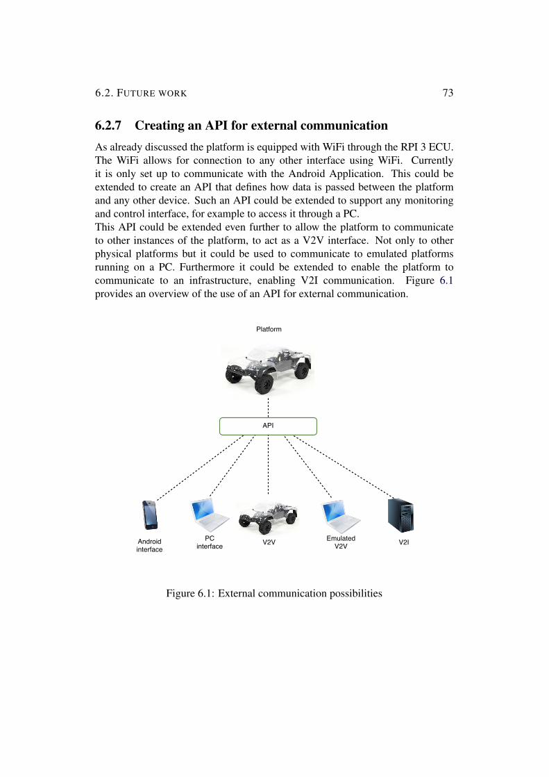
6.2. FUTURE WORK 73
6.2.7 Creating an API for external communicationAs already discussed the platform is equipped with WiFi through the RPI 3 ECU.The WiFi allows for connection to any other interface using WiFi. Currentlyit is only set up to communicate with the Android Application. This could beextended to create an API that defines how data is passed between the platformand any other device. Such an API could be extended to support any monitoringand control interface, for example to access it through a PC.This API could be extended even further to allow the platform to communicateto other instances of the platform, to act as a V2V interface. Not only to otherphysical platforms but it could be used to communicate to emulated platformsrunning on a PC. Furthermore it could be extended to enable the platform tocommunicate to an infrastructure, enabling V2I communication. Figure 6.1provides an overview of the use of an API for external communication.
Figure 6.1: External communication possibilities
6.2. FUTURE WORK 74
6.2.8 Improving the control and monitoring interfaceCurrently the car is controlled and monitored through a simple android applicationwith limited capabilities. The monitoring is, as previously discussed, limited toonly see the average ping and dropped packages of the internal car network. Thiscould be extended further to monitor sensors, actuators and the ECUs of the car.Furthermore the control interface could be improved to be more complete. Theway to control the steering and the speed is currently implemented using twosliders. This could be researched into to see what are the requirements to providea good interface.

Bibliography
[1] A. Davies. (2015) Turns out the hardware in self-driving cars ispretty cheap. Image. [Online]. Available: https://assets.wired.com/photos/w 1132/wp-content/uploads/2015/04/sensor info.jpg
[2] N. Instruments. (2016) Flexray automotive communication bus overview.Image. [Online]. Available: http://www.ni.com/cms/images/devzone/tut/FlexRay Cycle Overview.png
[3] G. A. Donahue, Network Warrior, 2nd Edition. 101 Morris Street,Sebastopol, CA 95472.: O’Reilly Media, Inc, 2011. ISBN 9781449307974
[4] M. J. Teener. (2009) Traffic-shaping. Image. [Online]. Available:hhttps://upload.wikimedia.org/wikipedia/en/d/d3/Traffic-shaping.pdf
[5] Autosar. (2016) Ecu software architecture. Image. [Online].Available: http://www.autosar.org/fileadmin/ processed /csm AUTOSARECU softw arch b fbf24b2245.jpg
[6] E. . Community. (2016) Beaglebone black rev. c development platformbased on ti sitara am3358 processor. Image. [Online]. Available:https://www.element14.com/community/dtss-images/uploads/devtool/image/large/BeagleBone+Black+Rev.+C+Development+Platform+based+on+TI+Sitara+AM3358+Processor+5511ec18a1d95.png
[7] Jasonreeder. (2016) Step 5. Image. [Online]. Available: http://processors.wiki.ti.com/images/0/02/Step5 2 0 2 11.PNG
[8] ——. (2016) Rpmsg diagram. Image. [Online]. Available: http://processors.wiki.ti.com/images/d/da/Rpmsg diagram 2 0 2 11.PNG
[9] R. P. FOUNDATION. (2016) Raspberry pi 3 model b. Image.[Online]. Available: https://www.raspberrypi.org/wp-content/uploads/2016/02/IMG 4090.jpg
75

BIBLIOGRAPHY 76
[10] T. M. Magazine. (2016) Raspberry pi camera module v2 released! Image.[Online]. Available: https://www.raspberrypi.org/magpi/wp-content/uploads/2016/04/camera module 1.jpg
[11] L. TP-Link Technologies Co. (2016) 5-port gigabit easy smart switchtl-sg105e. Image. [Online]. Available: http://static.tp-link.com/res/images/products/TL-SG105E un V1 873 68 large 0 20150212172231.jpg
[12] H. King. (2016) Turnigy sct 2wd 1/10 brushless short coursetruck (kit) upgraded version. Image. [Online]. Available: https://hobbyking.com/media/catalog/product/cache/1/thumbnail/565x414/9df78eab33525d08d6e5fb8d27136e95/legacy/catalog/51509 12 3.jpg
[13] K. . Company. (2016) Avstandsmatare for arduino. Image. [Online].Available: https://www.kjell.com/se/image/Product 238450sv/full/1
[14] M. A. Brown. (2006) pfifo fast queuing discipline. Image. [Online].Available: http://linux-ip.net/articles/Traffic-Control-HOWTO/images/pfifo fast-qdisc.png
[15] E. Commision. (2017) Statistics - accidents data. [Online]. Available:http://ec.europa.eu/transport/road safety/specialist/statistics en
[16] I. Riches, “Automotive ethernet market growth outlook,” Presentation,2014. [Online]. Available: https://standards.ieee.org/events/automotive/2014/00 Automotive Ethernet Market Growth Outlook.pdf
[17] Wikipedia. (2016) Advanced driver assistance systems. [Online].Available: https://en.wikipedia.org/wiki/Advanced driver assistancesystems
[18] Patrick Planing, Innovation Acceptance. Stuttgart, Germany: SpringerGabler, 2013. ISBN 978-3-658-05005-4 (eBook)
[19] A. Davies. (2015) Turns out the hardware in self-driving cars ispretty cheap. [Online]. Available: https://www.wired.com/2015/04/cost-of-sensors-autonomous-cars/
[20] A. Hakansson, “Portal of research methods and methodologies forresearch projects and degree projects,” in Proceedings of the InternationalConference on Frontiers in Education: Computer Science and ComputerEngineering FECS’13. Las Vegas USA: CSREA Press U.S.A, 2013, pp.67–73.

BIBLIOGRAPHY 77
[21] D. Hughey. (2009) The traditional waterfall approach. [Online]. Available:http://www.umsl.edu/∼hugheyd/is6840/waterfall.html
[22] Wikipedia. (2016) Electronic control unit. [Online]. Available: https://en.wikipedia.org/wiki/Electronic control unit
[23] T. Kirsten Matheus, Automotive Ethernet. Munchen, Germany:Cambridge University Press, 2015. ISBN 978-1-107-05728-9 Hardback
[24] p. m. m. Frederic Gaillard and A. Andreas Eieland, senior productmarketing manager, “Microprocessor (mpu) or microcontroller (mcu)?what factors should you consider when selecting the right processingdevice for your next design,” Article, 2013. [Online]. Available:http://www.atmel.com/Images/MCU vs MPU Article.pdf
[25] Atmel, “Atmel avr microcontrollers for automotive,” Brochure,2013. [Online]. Available: http://www.atmel.com/Images/Atmel-4073-AVR-Microcontrollersfor-Automotive Brochure.pdf
[26] T. Agarwal. (2016) Pic microcontroller architecture andapplications. [Online]. Available: https://www.edgefx.in/pic-microcontroller-architecture-and-applications/
[27] R. Bannatyne, “Microcontrollers for the automobile,” Micro ControlJournal, 2009, accessed 2017-01-05. [Online]. Available: http://www.mcjournal.com/articles/arc105/arc105.htm
[28] T. Instruments. (2017) Automotive processors overview.[Online]. Available: http://www.ti.com/lsds/ti/processors/dsp/automotiveprocessors/overview.page
[29] ——. (2017) Tdax socs drive automotive adas technology leadership.[Online]. Available: http://www.ti.com/lsds/ti/processors/dsp/automotiveprocessors/tdax adas socs/overview.page
[30] A. A. Buksh. (2016) Automotive semiconductor marketgrows slightly in 2015 while ranks shift, ihs says. Pressrelease. [Online]. Available: https://technology.ihs.com/580273/automotive-semiconductor-market-grows-slightly-in-2015-while-ranks-shift-ihs-says
[31] N. Semiconductors. (2017) S32 arm processors µcontrollers. [Online]. Available: http://www.nxp.com/products/microcontrollers-and-processors/arm-processors/s32-arm-processors-microcontrollers:S32V200

BIBLIOGRAPHY 78
[32] Luca Delgrossi and y. . . Tao Zhang, VEHICLE SAFETYCOMMUNICATIONS. New Jersey, United States of America: JohnWiley & Sons, Inc. ISBN 978-1-118-13272-2
[33] Wikipedia. (2016) Autonomous cruise control system. [Online]. Available:https://en.wikipedia.org/wiki/Autonomous cruise control system
[34] ——. (2017) Collision avoidance system. [Online]. Available: https://en.wikipedia.org/wiki/Collision avoidance system
[35] ——. (2017) Lane departure warning system. [Online]. Available:https://en.wikipedia.org/wiki/Lane departure warning system
[36] ——. (2017) Blind spot monitor. [Online]. Available: https://en.wikipedia.org/wiki/Blind spot monitor
[37] ——. (2017) Global positioning system. [Online]. Available: https://en.wikipedia.org/wiki/Global Positioning System
[38] Arduinoinfo.info. (2017) Understanding the science behind the ultrasonicdistance sensor. [Online]. Available: http://arduino-info.wikispaces.com/Ultrasonic+Distance+Sensor
[39] S. M. LaValle. (2012) Odometry sensors. [Online]. Available: http://planning.cs.uiuc.edu/node576.html
[40] J. H. Britt, “Lane Detection, Calibration, and Attitude Determination witha Multi-Layer Lidar for Vehicle Safety Systems,” Master’s thesis, AuburnUniversity, Auburn, Alabama, 2010.
[41] A. G. The Bureau of Meteorology. (2017) How radar works. [Online].Available: http://www.bom.gov.au/australia/radar/about/what is radar.shtml
[42] W. Elmenreich, “Sensor fusion in time-triggered systems,” Ph.D.dissertation, Vienna University of Technology, Vienna, Austria, 2002.
[43] H. Estl. (2016) Sensor fusion – more than just the sum of itsparts! [Online]. Available: http://www.automotive-eetimes.com/news/sensor-fusion-more-just-sum-its-parts-0
[44] B. F. B. S. B. C. B. B. B. S. B. G. C. L. C. D. E. H. H. K. I. J. J. D. K.J. K. H. L. J. M. M. M. D. M. E. M. P. P. Z. R. V. S. J. T. L. T. K. V. S.Ahmed-Zaid, F., “Vehicle safety communications – applications (vsc-a),”U.S. Department of Transportation, Final Report DOT HS 811 492A.
BIBLIOGRAPHY 79
[45] Z. Peter Dr. Gaspar and Szilard Aradi, Highly Automated Vehicle Systems.BME MOGI, 2014. ISBN 978-963-313-173-2
[46] I. Markit. (2016) Correcting and replacing ihs clarifies autonomousvehicle sales forecast – expects 21 million sales globally inthe year 2035 and nearly 76 million sold globally through 2035.[Online]. Available: http://news.ihsmarkit.com/press-release/automotive/autonomous-vehicle-sales-set-reach-21-million-globally-2035-ihs-says
[47] Waymo. (2017) Journey. [Online]. Available: https://waymo.com/journey/
[48] Kvaser. (2017) Introduction to the lin bus. [Online]. Available: https://www.kvaser.com/about-can/can-standards/linbus/
[49] Dominique Paret, Multiplexed Networks for Embedded Systems. Dunod,Paris: John Wiley & Sons Ltd,, 2005. ISBN 978-0-470-03416-3 (HB)Translated by Roderick Riesco, MA.
[50] J. Scoltock. (2013) Milestones: Flexray. [Online]. Available: http://ae-plus.com/milestones/milestones-flexray
[51] N. Instruments, “Flexray automotive communication bus overview,”National Instruments, White paper.
[52] F. S.-L. Nicolas Navet, “In-vehicle communication networks - a historicalperspective and review,” University of Luxembourg, Univerite de Lorraine,Tech. Rep.
[53] I. . E. W. GROUP. (2015) Ieee p802.3bm 40 gb/s and 100 gb/s fiber optictask force home page. [Online]. Available: http://www.ieee802.org/3/bm/
[54] A. Laurent Toutain, Local Networks and the Internet. 27-37 St George’sRoad ,London SW19 4EU, UK,111 River Street, Hoboken, NJ 07030,USA: John Wiley & Sons, Inc., ISTE Ltd, 2011. ISBN 978-1-84821-068-4
[55] C. E. Spurgeon, Ethernet: The Definitive Guide. 101 Morris Street,Sebastopol, CA 95472.: O’Reilly & Associates, Inc., 2000. ISBN 1-56592-660-9
[56] E. Tetz. (2017) Effect of a network loop. [Online]. Available: http://www.dummies.com/programming/networking/cisco/effect-of-a-network-loop/
[57] D. Fedyk, “Introduction to shortest path bridging ieee 802.1aq,”Presentation, 2012. [Online]. Available: https://www.netnod.se/sites/default/files/SPB-fedyk-091012.pdf

BIBLIOGRAPHY 80
[58] R. van der Pol, “Trill and ieee 802.1aq overview,” SURF, Tech. Rep.
[59] M. S. Guragain, “EVALUATING THE FUTURE OF THE SPANNINGTREE PROTOCOL,” BACHELOR’S THESIS, TURKU UNIVERSITYOF APPLIED SCIENCES, 2016.
[60] A. Alliance. (2017) Faqs. [Online]. Available: http://avnu.org/faqs/
[61] C. T. Andy Gothard, Rick Kreifeldt, “Avb for automotive use,” AvnuAlliance, White Paper, October 2014.
[62] A. Alliance. (2017) Automotive. [Online]. Available: http://avnu.org/automotive/
[63] I. . L. S. Committee. (2010) 802.1as - timing and synchronization.[Online]. Available: http://www.ieee802.org/1/pages/802.1as.html
[64] ——. (2010) 802.1qat - stream reservation protocol. [Online]. Available:http://www.ieee802.org/1/pages/802.1at.html
[65] ——. (2009) 802.1qav - forwarding and queuing enhancements fortime-sensitive streams. [Online]. Available: http://www.ieee802.org/1/pages/802.1av.html
[66] ——. (2016) 802.1ba - audio video bridging (avb) systems. [Online].Available: http://www.ieee802.org/1/pages/802.1ba.html
[67] “Ieee standard for layer 2 transport protocol for time sensitive applicationsin a bridged local area network,” IEEE Std 1722-2011, pp. 1–65, May 2011.doi: 10.1109/IEEESTD.2011.5764875
[68] “Ieee standard for device discovery, connection management, and controlprotocol for ieee 1722(tm) based devices,” IEEE Std 1722.1-2013, pp. 1–366, Oct 2013. doi: 10.1109/IEEESTD.2013.6627916
[69] S. Varadarajan. (1997) Virtual local area networks. [Online]. Available:http://www.cse.wustl.edu/∼jain/cis788-97/ftp/virtual lans/#WhyVLAN
[70]
[71] T. Simmons. (2015) Vlan 101: What are the benefits of usingvlans? [Online]. Available: https://nsxinsight.wordpress.com/2015/02/06/vlan-101-what-are-the-benefits-of-using-vlans/
[72] D. R. C. Mahaney. (2015) Vlan - benefits and limitations. [Online].Available: http://www.people.eku.edu/mahaneyb/CISStudentClub/1007/

BIBLIOGRAPHY 81
[73] Cisco. (2006) Inter-switch link and ieee 802.1q frame format. [Online].Available: http://www.cisco.com/c/en/us/support/docs/lan-switching/8021q/17056-741-4.html
[74] P. J. T. H. T. K. S. O. K. S. Franz Rammig, Michael Ditze, “Basic conceptsof real time operating systems,” in Hardware-dependent Software, R. D.JW. Ecker, W. Muller, Ed. Springer Science + Business Media B.V.
[75] G. Sally, Pro Linux Embedded Systems. United States of America: Apress,2010. ISBN 978-1-4302-7226-7
[76] E. Juliussen. (2014) Software platforms: A crucial infotainmentbattleground. [Online]. Available: https://www.ihs.com/newsletter/automotive/june-2014/infotainment-battleground.html
[77] Wikipedia. (2016) Qnx. [Online]. Available: https://en.wikipedia.org/wiki/QNX
[78] Microsoft. (2017) Create operational intelligence. [Online].Available: https://www.microsoft.com/windowsembedded/en-us/products-solutions-overview.aspx
[79] ——. (2017) Windows embedded automotive 7. [Online].Available: https://www.microsoft.com/windowsembedded/en-us/windows-embedded-automotive-7.aspx
[80] L. Foundation. (2017) About. [Online]. Available: https://www.automotivelinux.org/about
[81] P. Shelly, “Operating systems for cars,” Presentation, 2016. [Online].Available: https://evroadmapconference.com/program/presentations/PatShelly.pdf
[82] Autosar. (2016) Ecu software architecture. [Online]. Available: http://www.autosar.org/about/technical-overview/ecu-software-architecture/
[83] ——. (2016) Software component. [Online]. Available: http://www.autosar.org/about/technical-overview/software-component/
[84] ——. (2016) Autosar runtime environment. [Online].Available: http://www.autosar.org/about/technical-overview/ecu-software-architecture/autosar-runtime-environment/

BIBLIOGRAPHY 82
[85] ——. (2016) Autosar basic software. [Online]. Available: http://www.autosar.org/about/technical-overview/ecu-software-architecture/autosar-basic-software
[86] D. Molloy, Exploring BeagleBone. 10475 Crosspoint BoulevardIndianapolis, IN 46256: John Wiley & Sons, Inc., 2015. ISBN 978-1-118-93521-7
[87] R. Luotao Fu. (2016) Rt preempt howto. [Online]. Available: https://rt.wiki.kernel.org/index.php/RT PREEMPT HOWTO
[88] A. Garg, “Real-time linux kernel scheduler,” Linux Journal, no. 184, 2009.doi: http://www.linuxjournal.com/article/10165
[89] Z. N. S. Z. E. J. Jakob Axelsson, Avenir Kobetski, “Moped: A mobileopen platform for experimental design of cyber-physical systems,” SwedishInstitute of Computer Science (SICS), Tech. Rep.
[90] BeagleBoard.org. (2016) Beaglebone. [Online]. Available: http://beagleboard.org/bone
[91] T. Instruments, AM335x SitaraTM Processors, Texas Instruments, 2016,revised April 2016.
[92] ——. (2016) Pru-icss remoteproc and rpmsg. [Online]. Available: http://processors.wiki.ti.com/index.php/PRU-ICSS Remoteproc and RPMsg
[93] Elinux.org. (2016) Beaglebone black features. [Online]. Available: http://elinux.org/Beagleboard:BeagleBoneBlack#BeagleBone Black Features
[94] Sparkfun. (2017) Sparkfun ftdi basic breakout - 5v. [Online]. Available:https://www.sparkfun.com/products/9716
[95] T. M. Magazine. (2016) Raspberry pi 3 is out now! specs,benchmarks & more. [Online]. Available: https://www.raspberrypi.org/magpi/raspberry-pi-3-specs-benchmarks/
[96] R. P. FOUNDATION. (2016) Camera module v2. [Online]. Available:https://www.raspberrypi.org/products/camera-module-v2/
[97] L. TP-LINK TECHNOLOGIES CO., User Guide: TL-SG105E/TL-SG108E/TL-SG108PE TL-SG1016DE/TL-SG1024DE Gigabit EasySmart Switch, 2015, language = English, organization = TP-LINKTECHNOLOGIES CO., LTD, note = ”Available: http://static.tp-link.com/res/down/doc/TL-SG105 V2 UG.pdf”,.

BIBLIOGRAPHY 83
[98] W. Stallings. (2002) Quality of service (qos) for local area networks(lans). [Online]. Available: http://www.informit.com/articles/article.aspx?p=25315&seqNum=4
[99] Wikipedia. (2016) Brushless dc electric motor. [Online]. Available:https://en.wikipedia.org/wiki/Brushless DC electric motor
[100] T. Agarwal. (2015) Introduction to electronic speed control (esc)working and applications. [Online]. Available: https://www.elprocus.com/electronic-speed-control-esc-working-applications/
[101] Wikipedia. (2016) Android (operating system). [Online]. Available:https://en.wikipedia.org/wiki/Android (operating system)
[102] C. T. S. Bhd., User’s Manual, 2013, language = English, organization =Cytron Technologies Sdn. Bhd., version = V1.0.
[103] Photologic Reflective Object Sensor, 2015, language = English,organization = TT Electronics PLC, note = ”Available:http://www.mouser.com/ds/2/414/OPB715-716-717-718-42854.pdf”.
[104] S. Electronics. (2016) Sparkfun imu breakout - mpu-9250. [Online].Available: https://www.sparkfun.com/products/13762
[105] M. A. Brown. (2006) 6. classless queuing disciplines (qdiscs).[Online]. Available: http://linux-ip.net/articles/Traffic-Control-HOWTO/classless-qdiscs.html
[106] Wireshark. (2017) About wireshark. [Online]. Available: https://www.wireshark.org/
[107] F. Rowand, “Using and understanding the real-time cyclictest benchmark,”Presentation, 2013. [Online]. Available: http://events.linuxfoundation.org/sites/events/files/slides/cyclictest.pdf
[108] T. Instruments, “Building blocks for pru development,” Presentation, 2015.[Online]. Available: https://training.ti.com/system/files/docs/Building%20Blocks%20for%20PRU%20Development%20Slides.pdf
[109] R. Nelson. (2017) Beaglebone black. [Online]. Available: https://eewiki.net/display/linuxonarm/BeagleBone+Black
[110] ——. (2017) dtb-rebuilder. [Online]. Available: https://github.com/RobertCNelson/dtb-rebuilder
BIBLIOGRAPHY 84
[111] poopgiggle. (2016) pru-software-support-package. [Online]. Available:https://github.com/poopgiggle/pru-software-support-package
[112] M. A. Yoder. (2016) Ebc exercise 30 pru via remoteproc andrpmsg. [Online]. Available: http://elinux.org/EBC Exercise 30 PRU viaremoteproc and RPMsg
[113] F. Durr. (2015) kernel-4.4.9-rt17.tgz. Downloadable File. [Online].Available: http://download.frank-durr.de/kernel-4.4.9-rt17.tgz
[114] R. P. Foundation. (2016) Raspbian. [Online]. Available: https://www.raspberrypi.org/downloads/raspbian/
[115] F. Durr. (2015) Raspberry pi going realtime with rt preempt. [Online].Available: http://www.frank-durr.de/?p=203
[116] eLinux.org. (2016) Beagleboard/gsoc/ideas-2016. [Online].Available: http://elinux.org/BeagleBoard/GSoC/Ideas-2016#Open-AVBsupport for BeagleBone

Appendix A
Code
Listing A.1: Example code controlling multiple PWM signals
# i n c l u d e < s t d i n t . h># i n c l u d e < s t d i o . h># i n c l u d e < s t d l i b . h># i n c l u d e <p r u i e p . h># i n c l u d e <p r u i n t c . h># i n c l u d e ” s e r v o c o n t r o l l e r . h ”
v o l a t i l e r e g i s t e r u i n t 3 2 t R30 ; / * o u t p u t r e g i s t e r* /
i n t s e t u p s e r v o ( ) { / * t o i n i t t i m e r * /CT IEP . TMR GLB CFG bit . CNT EN = 0 ; / *
D i s a b l e c o u n t e r * /CT IEP . TMR CNT = 0x0 ; / *
R e s e t Count r e g i s t e r * /CT IEP . TMR GLB STS bit . CNT OVF = 0x1 ; / *
Clear o v e r f l o w s t a t u s r e g i s t e r * /CT IEP . TMR CMP STS bit . CMP HIT = 0xFF ;
/ * Clear compare s t a t u s * /CT IEP . TMR COMPEN bit . COMPEN CNT = 0x0 ;
/ * D i s a b l e c o m p e n s a t i o n * /CT IEP . TMR CMP CFG bit . CMP0 RST CNT EN = 0x0 ;
85

86
/ * D i s a b l e CMP0 and r e s e t on e v e n t * /CT IEP . TMR CMP CFG bit . CMP EN = 0x0 ; / * d i s a b l e
a l l compara tor s * /c o m p a r a t o r e n = 0 ; / * make s u r e i t i s 0 * /CT IEP . TMR GLB CFG bit . DEFAULT INC = 0x1 ; / *
C o n f i g u r e i n c r v a l u e * /}
i n t s e t g l o b a l p e r i o d ( i n t p e r i o d u s ) { / * use cmp0 −n o r m a l l y 20 ms / 50 hz * /
CT IEP . TMR CMP0 = CMP US * p e r i o d u s ;CMP0 EN = 0x1 ;c o m p a r a t o r e n = c o m p a r a t o r e n | CMP0 EN ;
}
i n t s e t s e r v o 0 d u t y ( i n t d u t y u s ) { / * use cmp1 * /CT IEP . TMR CMP1 = CMP US * d u t y u s ;CMP1 EN = 0x2 ;c o m p a r a t o r e n = c o m p a r a t o r e n | CMP1 EN ;
}i n t s e t s e r v o 1 d u t y ( i n t d u t y u s ) { / * use cmp2 * /
CT IEP . TMR CMP2 = CMP US * d u t y u s ;CMP2 EN = 0x4 ;c o m p a r a t o r e n = c o m p a r a t o r e n | CMP2 EN ;
}i n t s e t s e r v o 2 d u t y ( i n t d u t y u s ) { / * use cmp3 * /
CT IEP . TMR CMP3 = CMP US * d u t y u s ;CMP3 EN = 0x8 ;c o m p a r a t o r e n = c o m p a r a t o r e n | CMP3 EN ; / * b i t 3 −
e n a b l e t h e compara tor * /}
i n t s t a r t s e r v o s ( ) {/ * p e r i o d s e t u p * /CT IEP . TMR CMP CFG bit . CMP EN = c o m p a r a t o r e n ; / *
e n a b l e a l l compara to r s needed * /CT IEP . TMR GLB CFG bit . CNT EN = 1 ; / * e n a b l e t i m e r
c o u n t e r * /}i n t s t o p s e r v o s ( ) {

87
CT IEP . TMR CMP CFG bit . CMP EN = 0x0 ; / * d i s a b l e a l lcompara tor s * /
R30 = 0x0 ; / * s e t a l l p i n s t o low * /re turn 0 ;
}
i n t c h e c k s e r v o e v t ( ) { / * t o check i f t h e t i m e r causedan i n t e r u p t − and which o f t h e compara tor s i t was* /
i f ( CT INTC . HIPIR1 == PRU IEP EVT ) { / * i f t h e t i m e ri s o f h i g h e s t p r i o * /
/ * I d e n t i f y which compara tor caused t h ei n t e r u p t * /
i f ( ( CT IEP . TMR CMP STS bit . CMP HIT & CMP3 EN)== CMP3 EN) { / * i f cmp3 f i r e d t h e i n t e r u p t * /
R30 = R30 & 0xFFFFFFFB ; / * s e t b i t 1 t o0 * /
CT IEP . TMR CMP STS bit . CMP HIT = CT IEP .TMR CMP STS bit . CMP HIT | CMP3 EN ;
}i f ( ( CT IEP . TMR CMP STS bit . CMP HIT & CMP2 EN)
== CMP2 EN) { / * i f cmp2 f i r e d t h e i n t e r u p t* /
R30 = R30 & 0xFFFFFFFD ; / * s e t b i t 1 t o0 * /
CT IEP . TMR CMP STS bit . CMP HIT = CT IEP .TMR CMP STS bit . CMP HIT | CMP2 EN ; / *Clear e v e n t * /
}i f ( ( CT IEP . TMR CMP STS bit . CMP HIT & CMP1 EN)
== CMP1 EN) { / * i f cmp1 f i r e d t h e i n t e r u p t* /
R30 = R30 & 0xFFFFFFFE ; / * s e t b i t 0 t o0 * /
CT IEP . TMR CMP STS bit . CMP HIT = CT IEP .TMR CMP STS bit . CMP HIT | CMP1 EN ; / *Clear e v e n t * /
}i f ( ( CT IEP . TMR CMP STS bit . CMP HIT & CMP0 EN)
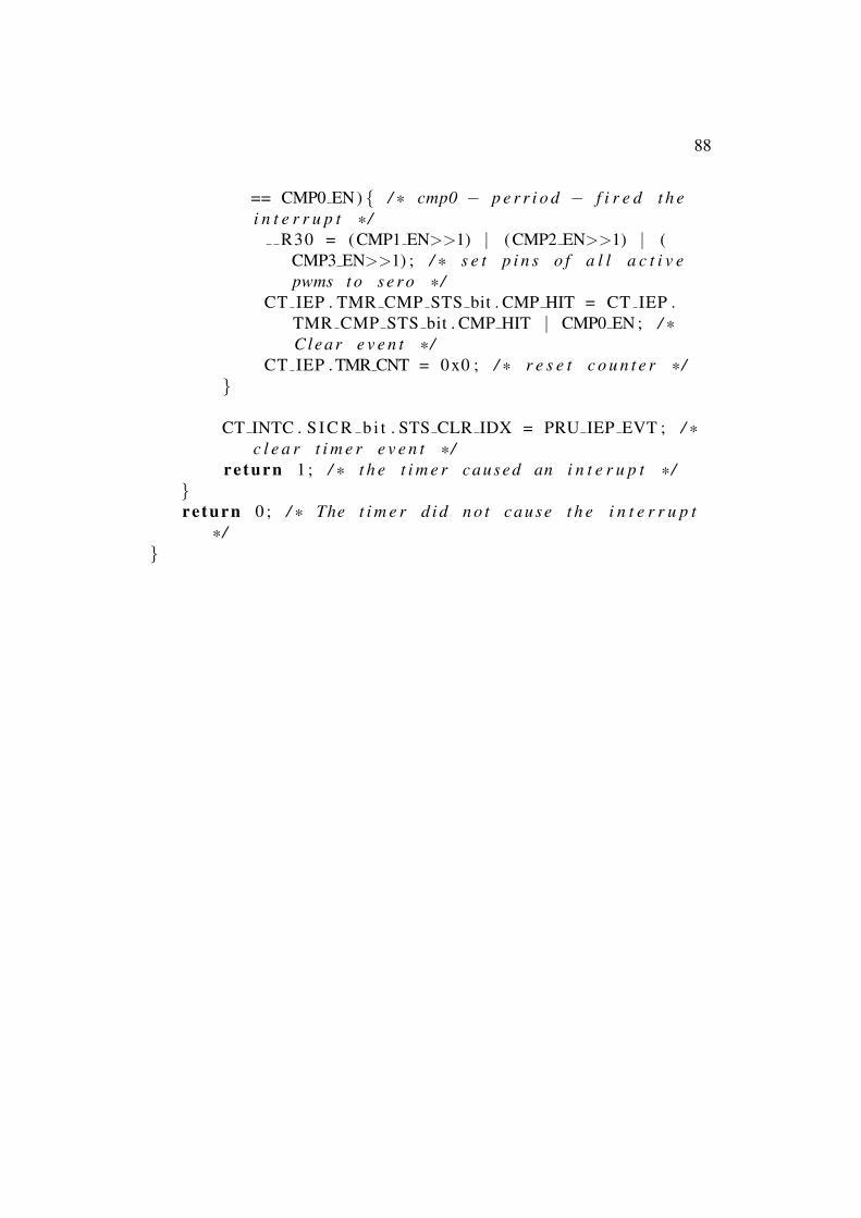
88
== CMP0 EN) { / * cmp0 − p e r r i o d − f i r e d t h ei n t e r r u p t * /
R30 = (CMP1 EN>>1) | (CMP2 EN>>1) | (CMP3 EN>>1) ; / * s e t p i n s o f a l l a c t i v epwms t o s e r o * /
CT IEP . TMR CMP STS bit . CMP HIT = CT IEP .TMR CMP STS bit . CMP HIT | CMP0 EN ; / *Clear e v e n t * /
CT IEP . TMR CNT = 0x0 ; / * r e s e t c o u n t e r * /}
CT INTC . S I C R b i t . STS CLR IDX = PRU IEP EVT ; / *c l e a r t i m e r e v e n t * /
re turn 1 ; / * t h e t i m e r caused an i n t e r u p t * /}re turn 0 ; / * The t i m e r d i d n o t cause t h e i n t e r r u p t
* /}

TRITA TRITA-ICT-EX-2017:3
www.kth.se