design and implementation of broad band and narrow band antennas
TRANSCRIPT

APPROVED: Hualiang Zhang, Major Professor Gayatri Mehta, Committee Member Xinrong Li, Committee Member Shengli Fu, Graduate Program Coordinator Murali Varanasi, Chair of the Department of
Electrical Engineering Costas Tsatsoulis, Dean of the College of
Engineering James D. Meernik, Acting Dean of the
Toulouse Graduate School
DESIGN AND IMPLEMENTATION OF BROAD BAND AND NARROW
BAND ANTENNAS AND THEIR APPLICATIONS
Zeeshan Salmani
Thesis Prepared for the Degree of
MASTER OF SCIENCE
UNIVERSITY OF NORTH TEXAS
August 2011

Salmani, Zeeshan. Design and Implementation of Broad Band and Narrow
Band Antennas and Their Applications. Master of Science (Electrical Engineering),
August 2011, 41 pp., 2 tables, 22 illustrations, references, 31 titles.
The thesis deals with the design and implementation of broadband and
narrowband antennas and their applications in practical environment. In this thesis, a
new concept for designing the UWB antenna is proposed based on the CRLH
metamaterials and this UWB antenna covers a frequency range from 2.45 GHz to 11.6
GHz. Based on the design of the UWB antenna, another antenna is developed that can
cover a very wide bandwidth i.e from 0.66 GHz to 120 GHz. This antenna can not
only be used for UWB applications but also for other communication systems
working below the UWB spectrum such as GSM, GPS, PCS and Bluetooth. The
proposed antenna covering the bandwidth from 0.66 GHz to 120 GHz is by far the
largest bandwidth antenna developed based on metamaterials. Wide band antennas are
not preferred for sensing purpose as it is difficult to differentiate the received signals.
A multiband antenna which can be used as a strain sensor for structural health
monitoring is proposed. The idea is to correlate the strain applied along the length or
width with the multiple resonant frequencies. This gives the advantage of detecting
the strain applied along any direction (either length or width), thus increasing the
sensing accuracy. Design and application of a narrow-band antenna as a temperature
sensor is also presented. This sensor can be used to detect very high temperature
changes (>10000C). This sensor does not require a battery, can be probed wirelessly,
simple and can be easily fabricated, can withstand harsh environmental conditions.

ii
Copyright 2011
by
Zeeshan Salmani

iii
ACKNOWLEDGEMENTS
I would like to express my sincere appreciation and gratefulness to my major
advisor Dr. Hualiang Zhang for his knowledge, insight, guidance, constant mentoring
and support throughout my entire research. Indeed, my gratitude to him cannot be
expressed in few words and it was an honor to be his student. Appreciation is also
extended to my friends and lab mates with whom I had some good conversations
about all subjects in life and whose unconditional support and strength made every
day enjoyable. I would like to thank my advisory committee members Dr. Xinrong Li,
Dr. Gayatri Mehta and other faculty and staff members of the electrical engineering
department for their moral support.
I am eternally indebted to my sister who has always been caring, loving and a
constant source of inspiration. Lastly, and most importantly, I want to thank my
parents. They bore me, raised me, supported me, taught me, and loved me. To them I
dedicate this thesis.

iv
TABLE OF CONTENTS
Page ACKNOWLEDGEMENTS ......................................................................................... iii LIST OF TABLES .........................................................................................................v LIST OF ILLUSTRATIONS ....................................................................................... vi Chapters
1. INTRODUCTION .................................................................................1
1.1 Motivation ..................................................................................1
1.2 Contributions of the Thesis ........................................................3
1.3 Overview of the Thesis ..............................................................4 2. ULTRA-WIDEBAND (UWB) AND VERY WIDE-BAND ANTENNA ........................................................................................................6
2.1 Motivation ..................................................................................6
2.2 Antenna Design ..........................................................................7
2.3 Results and Discussion ............................................................10
2.4 Summary ..................................................................................21 3. STRAIN AND TEMPERATURE SENSOR .......................................22
3.1 Motivation for Strain Sensor Antenna .....................................22
3.2 Antenna Design and Simulated Results ...................................24
3.3 Testing of Antenna ...................................................................26
3.4 Measured Results .....................................................................27
3.5 Motivation for Temperature Sensing Antenna ........................29
3.6 Temperature Sensor Design Principle and Results ..................30
3.7 Summary ..................................................................................32 4. CONCLUSIONS..................................................................................33
APPENDIX: LIST OF PUBLICATIONS ...................................................................35 REFERENCES ............................................................................................................37

v
LIST OF TABLES
Page 3.1 AUT with different bending and corresponding strains ..................................28
3.2 AUT with different bending and corresponding frequency change .................28

vi
LIST OF FIGURES
Page
2.1 Topology of single element used in UWB antenna ...........................................9
2.2 Cross section of a parallel strip transmission line ............................................10
2.3 Schematic of proposed UWB antenna .............................................................10
2.4 Simulated VSWR of proposed UWB antenna .................................................12
2.5 Effect of parameter a on VSWR ......................................................................12
2.6 Effect of parameter Z on VSWR .....................................................................13
2.7 Fabricated antenna structure ............................................................................14
2.8 Measured VSWR of fabricated antenna structure ...........................................14
2.9 (a) Radiation patterns in E plane ......................................................................15
2.9 (b) Radiation patterns in H plane .....................................................................16
2.10 Fabricated very wide band antenna..................................................................17
2.11 Simulated and measured results of the scaled antenna ....................................17
2.12 Simulated and measured results for lower frequencies ....................................18
2.13 Measured gain of very wide band antenna ......................................................18
2.14 (a) Radiation patterns for E plane (scaled antenna) .........................................19
2.14 (b) Radiation patterns for H plane (scaled antenna) ........................................20
3.1 Topology of the proposed strain sensor antenna..............................................25
3.2 Simulated antenna performance with different bending ..................................26
3.3 Test arrangement for strain measurement ........................................................26
3.4 Measured results of the strain sensor ...............................................................28
3.5 Topology of temperature sensor antenna .........................................................31
3.6 Simulated results of temperature sensor ..........................................................31

CHAPTER 1
INTRODUCTION
1.1 Motivation
IEEE defines antenna as a means for radiating or receiving waves. There are
various types of antennas such as wire antennas, aperture antennas, microstrip
antennas, array antennas, reflector and lens antennas. Wire antenna is the simplest of
all antennas. It may take various forms such as rectangle, square, circle etc. Aperture
antennas operate at higher frequencies and are useful for aircraft applications. The
period during and after the World War II saw the advancement of the antenna from a
simple wire to several other radiators such as slots, horns, reflectors, etc. The patch
antenna was introduced in early 1970s and received a lot of attention since then.
Microstrip antennas have been considered as excellent radiators due to their merits
such as low profile and broadside radiation patterns [1]. Microstrip antennas are easy
to fabricate and can be fed easily with a coaxial cable, microstrip line, etc apart from
being easily integrable in an array. A single element has relatively wide radiation
pattern and in order to achieve specific radiation patterns or high directivity, the
electrical size of the single element can be increased. This technique seems good but
is marred by mechanical problems. Another technique is to use multiple elements of
the same size and form an array to achieve the required directivity. However, an
efficient feeding network has to be designed to make the best efficient use of the
array. Arrays form the best antenna systems. An array with identical elements is
simple and easy to implement but this is not always necessary. In order to achieve
1
high directive beam, it is necessary that the fields from all the elements of an array
interfere constructively in the desired direction and destructively in other directions.
The interference of the fields depends upon the spacing of the elements. Future wireless communication systems particularly the Ultra wideband
(UWB) systems require antennas with simple geometry, small size and uniform
radiation characteristics. A conventional UWB antenna covers the frequency band
from 3.1 GHz to 10.6 GHz. In the past, many designs had been proposed to work at
this frequency band, where the goal was mostly concentrated on achieving the UWB
bandwidth using different techniques without compromising the performance. Slot
antennas, coupled slot antennas, planar monopole antennas, microstrip patch antennas
with coaxial, microstrip, or coplanar waveguide feeds are a few examples. However,
these antennas are limited to cover the conventional UWB bandwidth and any further
development to improve the bandwidth is very difficult if not impossible. A new
concept for designing UWB antennas covering wider bandwidth has to be developed
so that it can be used for several applications such as GSM, GPS, PCS, and Bluetooth
apart from UWB applications. In this thesis, we propose a new design for extremely
wideband antenna based on the concept of log periodic antenna array technique.
Structural health monitoring (SHM) systems provide reliable information
regarding the integrity of the structure such as building supports, bridges etc. SHM is
the process to detect the damage or changes in the geometric properties of the
structure before it exceeds the safety limit so that additional repairs and strengthening
techniques can be applied, thus eliminating the risk of a possible collapse in the
future. Various factors such as vibrations, cracks, ageing and natural disasters like
earthquakes can contribute to the structural disturbances. In order to detect such kind
2
of disturbances, SHM systems employ the strain measurement devices (e.g. strain
sensor). Strain sensor is an important tool for monitoring and measuring the stress
level in the structure as the load applied to it varies. Various strain sensors have been
presented in the past but they are followed by drawbacks such as sensitivity to
temperature, high cost, requires large space and battery. What we need is a simple
strain sensor which can be monitored remotely, can be fabricated easily, low cost and
does not require a battery.
A temperature sensor is a device which is used to predict accurate temperature
of any given environment and convert it to a form which can be easily understood by
any other device or observer. A good temperature sensor has to be very sensitive even
for small changes in temperature. Several temperature sensors have been proposed
such as Thermocouple based sensors, Resistance based temperature detectors
(RTD’s), thermistors and temperature –transducers IC’s. Even RFID based wireless
sensors have been proposed but they require a transceiver, a battery, a sensing
element and an interfacing circuit to transform the data to simple electrical signals.
However, even if we eliminate the cost of implementation of these sensors, they still
cannot be used for detecting the changes in very high temperatures (>10000C). A
simple temperature sensor that can be easily manufactured, can be easily implemented
to detect very high temperatures is needed, thus eliminating the drawbacks of
conventional temperature sensors.
1.2 Contribution of Thesis
In general, UWB system is not restricted to a single frequency band but can
transmit over a broad range of frequencies. This characteristic differentiates it from
other wireless technologies. The broad spectrum makes it resistant to interference,
3

jamming and accurate ranging. By further increasing the bandwidth, the proposed
UWB antenna can not only support the UWB spectrum, but also be used for many
other electronic / communication systems including GSM, GPS, PCS, and Bluetooth.
Moreover, the proposed antenna may find applications in radar systems, target
sensing, locating, tracking and indoor geo-location applications. Among all of these
applications, it is specifically useful for indoor geo-location systems to improve the
sensing accuracy. Indoor geo-location refers to accurate determination of position of
an object in an indoor environment where the probability to suffer from multi-path
effect is very high. Due to this, the currently used positioning systems cannot provide
accurate coverage for the indoor areas. This UWB antenna can be an ideal candidate
for indoor geo-location because of its wide bandwidth which makes it resistant to
interference and able to penetrate through concrete structures. The detailed analysis of
UWB systems suggests that UWB antennas can be used in all the cases where we
need a highly precise observation of objects at short distances. This antenna can also
be used for short distance communications usually between computer components
within a range of 10-15 meters.
Apart from UWB applications, there are various areas where the antennas can
be of immense help such as structural health monitoring (SHM) and temperature
sensor for sensing very high temperature changes .we have presented simple antenna
designs in this thesis which can be used for the said applications.
1.3 Overview of Thesis
In this thesis, I intend to present new design for UWB, dual band and slot
antennas and their applications.
4
Chapter 2 introduces a new design for extremely wideband antenna based on
the concept of log periodic antenna array technique. Detailed analysis along with
simulation and measured results are presented. Metamaterial based antennas are used
as the radiating elements. These radiating elements are connected together and fed
using parallel strip transmission lines. The proposed wideband antenna with its
increased bandwidth can not only support the UWB spectrum, but also be used for
many other electronic / communication systems including GSM, GPS, PCS, and
Bluetooth.
Chapter 3 presents the concept the structural health monitoring (SHM) and
temperature sensing using antennas. The concept on which the antennas have been
designed is explained in detail in this chapter. A multi-band antenna is presented
which can sense the strain along the length as well as width and also transmit the data,
thus eliminating the drawbacks of the previous strain sensors. A simple slot antenna is
also presented which can be used to detect the changes in temperatures >10000C. The
antenna performance is simulated by the full-wave electromagnetic simulator (HFSS)
and the simulation and measured results have been presented.
Finally, a conclusion is given in Chapter 4, where the future work for this
thesis is also provided.
5
CHAPTER 2
LOG-PERIODIC ANTENNA ARRAY INSPIRED PARALLEL STRIP ULTRA-
WIDEBAND (UWB) AND VERY WIDE-BAND ANTENNA
2.1 Motivation
Ultra-wideband (UWB) technology due to its high speed data rate
communications, high accuracy radars, excellent immunity to multipath interference
and large bandwidth has been attracting enormous interest worldwide. In general,
UWB system is not restricted to a single frequency band but can transmit over a broad
range of frequencies. This characteristic differentiates it from other wireless
technologies. The broad spectrum makes it resistant to interference, jamming and
accurate ranging. One of the key technologies in the UWB system that has been
widely investigated by both academia and industries is the antenna design. Several
antenna designs have been proposed since the release of the UWB spectrum by
Federal communication commission (FCC) in 2002 to satisfy this spectrum
requirement.
Recently, there has been a significant interest in developing low profile, light
weight, and easy to manufacture wideband antennas. Meanwhile, different types of
log periodic antennas due to its frequency independent characteristics have been
proposed to work over a wide range of frequencies. The implementation of log-
periodic principles in microstrip antennas is presented in [2-3], the characteristics of
microstrip antenna is improved by log-periodic technique. In [4], an array of
rectangular microstrip patches were arranged in log-periodic way and coupled to a
6

microstrip feedline. [5] Presents a dual feed log periodic antenna with high gain and
bandwidth. However, the size of these antennas is large due to the employment of
multiple radiating elements.
In this chapter, I propose a new design for extremely wideband antenna
based on the concept of log periodic antenna array technique. Metamaterial based
antennas are used as the radiating elements. These radiating elements are connected
together and fed using parallel strip transmission lines. The antenna performance is
simulated by the full-wave electromagnetic simulator (high frequency structure
simulator (HFSS)). The proposed wideband antenna with its increased bandwidth can
not only support the UWB spectrum, but also be used for many other electronic /
communication systems including GSM, GPS, PCS, and Bluetooth. Moreover, the
proposed antenna may find applications in radar systems, target sensing, locating,
tracking and indoor geo-location systems. Among all of these applications, it can be
specifically useful for indoor geo-location (where the probability to suffer from multi-
path effect is very high) to improve the sensing accuracy.
2.2 Antenna Design
The proposed antenna design is inspired by the concept of log-periodic
antenna array technique, where an array of radiating element with narrow bandwidth
is arranged in a log-periodic way to increase the bandwidth [2 - 5]. Based on this
technique, in this paper, two independent metamaterial based wideband antenna
elements have been designed covering different radiating frequencies and are
combined together to give more bandwidth. The basic design of the antenna element
used in the proposed UWB antenna is based on the concept of composite right/left-
7

handed (CRLH) metamaterial antenna [6]. Fig. 2.1 shows the structure of the antenna
element used in the proposed antenna. This antenna element consists of a circular
patch of radius R = 3.5mm, a semi-circular portion with wings and a straight section
to which the power is delivered through a parallel-strip line (this feeding line will be
discussed later). The length of the wings (L as labeled in Fig. 2.1) is 1.68mm each.
The semicircular portion feeds the circular patch through capacitive coupling. The gap
between the circular patch and the semicircular patch has to be designed carefully so
that there is enough generation of capacitance which is essential to get a better
matching throughout the entire bandwidth. If this coupling is too tight, the radiation
performance will be adversely affected. The bottom portion of the parallel stripline
behaves as a ground plane, and the width of it is chosen to be 8mm. The width of the
ground plane is pivotal for providing a better performance of the antenna element. A
metallic via connects the circular patch on the top layer to a via line at the bottom
layer which leads to the ground plane, providing parallel inductance. The radius of the
via is 0.3mm and the width of the via line is 0.2mm. The combination of the
inductance (induced by the via line) and the capacitance (induced by the coupling gap)
forms the CRLH type metamaterial, leading to a compact antenna design.
For the feeding of the proposed antenna, previously, most of the antennas were fed
by coaxial line [6], microstrip line [7]-[8], or CPW line [9]-[10], but in this chapter we
propose to use the parallel-strip lines. As shown in Fig. 2.2, a parallel-strip line is
made of a symmetrical pair of strip conductors on opposite faces of a dielectric
material which makes it compatible with double sided antennas and other balanced
microwave circuits [11 - 16]. Most importantly, this kind of transmission line can
provide the following attractive features: (1) it provides wide operating bandwidth; (2)
8

it is easy for the implementation of the log-periodic array concept; (3) it improves the
power handling capability along with reducing the complexity of circuit structures of
wide band transitions; and (4) it is easy for the realization of low characteristic
impedance line and good performance of balanced microwave components. All of
these properties have made it appealing to apply parallel-strip line in the proposed
UWB antenna. In this design, the width (W1 as labeled in Fig. 2.1) of the parallel
stripline is calculated to be matched to a characteristic impedance of 50 ohm (W1 as
labeled in Fig. 2.1) and is 2.2mm and the length (L1 as labeled in Fig. 2.1) was
determined to be 20.7mm.
L
R
L1
W1
Fig. 2.1. Topology of the antenna element used in the proposed UWB antenna:
(a) top view, (b) bottom view.
The final schematic of the proposed antenna is shown in Fig. 2.3, where two
antenna radiating elements (metamaterial based antenna) are connected with the help
of the parallel-strip lines. The first antenna element resonates well in the high
frequency band covering the frequencies from 5.2 GHz to 9.4 GHz. The second
antenna element is designed by scaling the first antenna element by a factor of 2.
9

However, in the second element the width and length of the parallel stripline is kept
same as the one used in first element. The second element covers the lower band with
the operating frequency ranging from 2.7 GHz to 5.2 GHz. The two antenna elements
have overlapping operating frequency band, which is essential to obtain a stable
performance in the resultant antenna bandwidth. The ground plane is adjusted in a
way such that both the antennas operate properly. The overall size of the proposed
antenna is 40 mm by 40 mm.
hr
w
Fig. 2.2. Cross section of a parallel strip transmission line.
W1
L
L2
a
b
Z
R1W2
(a) (b)
Fig. 2.3 Schematic of the proposed UWB antenna: (a) top view, (b) bottom view.
2.3 Results and Discussion
10

The numerical analysis of the proposed antenna is performed using the full-
wave simulation software HFSS. Through our simulations, an FR4 board is used with
thickness = 1mm, relative permittivity єr=4.4 and loss tangent=0.02. Fig. 2.4 shows
the simulated VSWR for the two individual antenna elements, covering the higher and
lower frequency bands. The first antenna element covering the higher frequency band
has a fractional bandwidth of 57.5% corresponding to a center frequency of 7.3 GHz
and the antenna element covering the lower frequency band has a fractional
bandwidth of 67.5% at a center frequency of 4 GHz. The whole performance of the
proposed antenna is also plotted in Fig. 4. It has a fractional bandwidth of 138% at
center frequency of 7 GHz; covering the frequency band from 2.45 GHz to 11.6 GHz
(the whole UWB band from 3.1 – 10.6 GHz is covered). As labeled in Fig. 2.3, the
physical dimensions of the designed antenna are: W1=2.2mm, W2=15mm,
L=1.68mm, L2=11mm, R1=7.4mm, a=0.2mm, b=1.4mm and Z=0mm. During our
simulations, it was found that several parameters will affect the antenna’s
performance. To study the effect of these parameters, parametric studies are
conducted. First, the effect of the width of the straight section of larger antenna
element (‘a’ as labeled in Fig. 2.3) is studied. Fig. 2.5 shows the simulated VSWRs
with the values of ‘a’ changing from 0.2mm to 1mm in a sweeping step of 0.2mm. It
is observed from this figure that the performance of the antenna in lower frequency
band will be affected greatly by this parameter. As a compromise of the antenna
performance and the fabrication resolution, a = 0.2 mm is used in the final design.
11
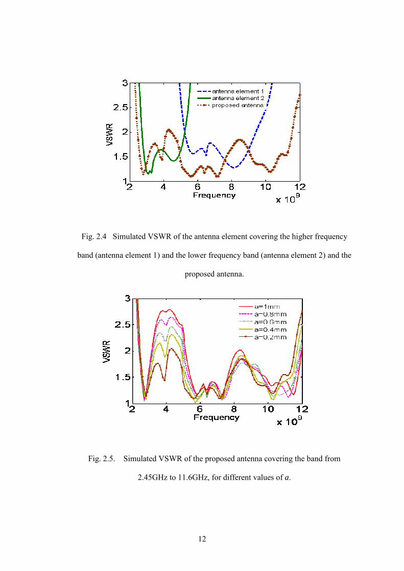
Fig. 2.4 Simulated VSWR of the antenna element covering the higher frequency
band (antenna element 1) and the lower frequency band (antenna element 2) and the
proposed antenna.
Fig. 2.5. Simulated VSWR of the proposed antenna covering the band from
2.45GHz to 11.6GHz, for different values of a.
12

Next, the effect of the parallel stripline length to the antenna’s performance
was studied. Fig. 2.6 presents the simulated results for different values of Z (as
labeled in Fig. 2.3). In our simulations, initially, the length of the parallel strip was
assumed to be 21.2mm (Z = 0.5mm). This parameter was then swept with a step size
of 0.5mm. It is found that the optimal antenna performance is achieved when Z =
0mm. In this case, the two straight sections of the antenna elements are exactly
aligned at the end of the strip. Fig. 2.7 shows the fabricated antenna structure and the
corresponding measured VSWR is presented in Fig. 2.8. The simulated and measured
results are in good agreement with each other. Finally, the radiation characteristics of
the proposed antenna at discrete frequencies over the whole operating frequency band
are plotted in Fig. 2.9. The proposed UWB antenna exhibits omni-directional
radiation patterns at lower frequencies. At the higher operating frequencies, the
original omni-directional radiation patterns are distorted.
Fig. 2.6. Simulated VSWR for different values of Z.
13

Fig. 2.7. Fabricated antenna structure: (a) top portion, (b) bottom portion.
2 4 6 8 10 12
x 109
1
1.5
2
2.5
Frequency
VS
WR
measured VSWR
Fig. 2.8. Measured VSWR of the proposed antenna
14

(a) (b)
(a) (b)
Fig. 2.9(a). Simulated and measured antenna’s radiation patterns at different
frequencies corresponding to E-plane co and cross polarization (a) 3 GHz (b) 7 GHz
(a) (b)
0
30
60
90
120
150
180
210
240
270
300
330
Simulated Measured0 dB
-10
-20
0
30
60
90
120
150180
210
240
270
300
330 simulated measured0 dB
-10
-20
-30
0
30
60
90
120
150
180
210
240
270
300
330
simulated measured0 dB
-10
-20
0
30
60
90
120
150
180
210
240
270
300
330 simulated measured0 dB
-10
-20
0
30
60
90
120
150
180
210
240
270
300
330 simulated measured0 dB
-10
-20
0
30
60
90
120
150
180
210
240
270
300
330 simulated measured0 dB
-10
-20
15

(a) (b)
Fig. 2.9 (b) Simulated and measured antenna’s radiation patterns at different
frequencies corresponding to H-plane co and cross polarization (a) 3 GHz (b) 7 GHz
In order to increase the bandwidth further and cover the much lower frequency
band, the antenna shown in Fig. 2.1 was then scaled by 4 times its original value.
After performing the optimization of several parameters of the scaled antenna,
resulted in an antenna resonating from 0.6GHz to 120GHz with a VSWR <2 for the
frequencies from 3.5GHz to 120 GHz and a VSWR<3 for frequencies from 0.6GHz to
3.5GHz. But the parallel strip was still maintained to give an impedance of 50 ohm at
lower frequency band and was modified accordingly. Fig. 2.10 shows the fabricated
very wide band antenna. Fig. 2.11 shows the simulated and measured return loss of
the scaled antenna from 0.6GHz to 120GHz and they are in good agreement with each
other. Fig. 2.12 shows the simulated and measured results for the frequencies from
0.6GHz to3GHz.
0
30
60
90
120
150
180
210
240
270
300
330 simulated measured0 dB
-10
0
30
60
90
120
150
180
210
240
270
300
330 simulated measured0 dB
-10
-20
16

(a) (b)
Fig. 2.10 Fabricated very wide band antenna: (a) top side, (b) bottom side
0.2 0.4 0.6 0.8 1 1.2 1.4 1.6 1.8 2
x 1010
-50
-40
-30
-20
-10
0
Frequency
dB S
cale
measured S11Simulated S11
Fig. 2.11. Simulated and measured results of the scaled antenna
17

1 1.5 2 2.5 3
x 109
-25
-20
-15
-10
-5
0
Frequency
dB
Sca
le
measured S11Simulated S11
Fig. 2.12. Simulated and measured results of the Scaled antenna for lower
frequencies
4 5 6 7 8 9 10 11
2
3
4
5
6
7
gai
n (in
dB)
Measured gain
Frequency (in GHz)
Fig. 2.13 Measured gain of the proposed wide band antenna
18

-150
-120
-90
-60
-300
30
60
90
120
150180
Simulated Measured
(a) (b)
(a) (b)
Fig. 2.14 (a). Simulated and measured radiation pattern for E-plane: (a) co
polarization, (b) cross polarization at 1GHz and 13GHz
-150
-120
-90
-60
-300
30
60
90
120
150180
-5 dB
Simulated Measured
0 dB
030
60
90
120
150180
210
240
270
300
330
-10 dB
simulated measured
0 dB0
30
60
90
120
150180
210
240
270
300
330
-10 dB
simulated measured
0 dB
19

(a) (b)
(a) (b)
Fig. 2.14 (b) Simulated and measured radiation pattern for H-plane: (a) co
polarization, (b) cross polarization at 1GHz and 13GHz
Gain of an antenna is defined as the ratio of the intensity in a given direction
to the radiation intensity radiated isotropically. Fig. 2.14 shows the measured gain of
the antenna over a frequency range from 4GHz to 10.6GHz. The max gain of 6.6dB is
obtained at 8.3GHz. Radiation patterns of the scaled antenna are shown in Fig. 2.14 (a)
and (b), both co and cross polarization in E and H plane. The patterns are omni
030
60
90
120
150180
210
240
270
300
330
-10 dB
simulated measured
0 dB
030
60
90
120
150180
210
240
270
300
330
-10 dB
simulated measured
0 dB
030
60
90
120
150180
210
240
270
300
330
-10 dB
simulated measured
0 dB0
30
60
90
120
150180
210
240
270
300
330
-10 dB
simulated measured
0 dB
20

directional at lower frequencies and distorted at higher frequencies due to higher order
modes.
2.4 Summary
A new design concept of UWB antenna is presented, proving that two
individual wideband antennas can be connected together in a way inspired by the log
periodic antenna array technique using a parallel stripline. The UWB antenna covers
the frequency band from 2.45 GHz to 11.6 GHz, defined with a VSWR < 2, thus
encompassing the bandwidth of the two individual antenna elements. The simulated
radiation patterns at different frequencies with the corresponding E-plane and H-plane
are also presented. Numerical results and measured results show that the proposed
antenna is suitable for various broadband applications. Further, to cover much lower
frequencies, the UWB antenna was scaled by a factor 4 and after several
modifications and optimizations of several conflicting parameters an extremely
wideband antenna was obtained which covers the bandwidth from 0.68GHz to 120
GHz, defined with a VSWR < 3 for frequency range of 0.68GHz to 3.3GHz and
VSWR<2 for 3.5GHz to 120GHz.
21

CHAPTER 3
APPLICATION OF ANTENNA IN STRAIN AND TEMPERATURE
MEASUREMENT
3.1 Motivation for Strain Measurement Antenna
Structural health monitoring (SHM) systems provide reliable information
regarding the integrity of the structure such as building supports, bridges etc. SHM is
the process to detect the damage or changes in the geometric properties of the
structure before it exceeds the safety limit so that additional repairs and strengthening
techniques can be applied, thus eliminating the risk of a possible collapse in the
future. Various factors such as vibrations, cracks, ageing and natural disasters like
earthquakes can contribute to the structural disturbances. In order to detect such kind
of disturbances, SHM systems employ the strain measurement devices (e.g. strain
sensor). Strain sensor is an important tool for monitoring and measuring the stress
level in the structure as the load applied to it varies. A variety of strain sensors have
been used in the past. Semiconductor strain gauge called the piezoresistor, based on
the piezoresistive effect is the commonly used strain gauge. Several piezoresisitive
strain sensors have been designed to be used for various strain measurements with an
excellent gauge factor [17-19]. However they are very sensitive to temperature
changes. In [20], it is proved that by increasing the doping level, piezoresistive
sensors which are less sensitive to temperature variation can be obtained but with
reduced gauge factor. They are also very delicate and hence it is difficult to
implement them in a commercial environment considering the complexity of the
network involved.
22
Recently, there has been a significant research on the optical fiber based strain
sensors. A detailed overview of applications of optical fibers in mechanical
measurements can be found in [21]. An optical fiber sensor with a linear relation
between transmitted light intensity and applied stress is presented in [22]. A twisted
pair of optical fiber has been used in [23] to determine the stress in an optical cable
due to thermal expansion. Optical fibers have the advantage of high bandwidth and
free from electromagnetic interference but high cost of implementation has made it
prohibitive for usage along with robustness of the sensor system, transduction, data
interpretation, stability and reliability [24].
Easy and low cost availability of RF transceivers and microcontrollers
resulted in the integration of wireless technology and sensing devices. A number of
wireless strain sensors have been presented in [25-27]. These wireless sensors require
batteries to charge along with a complex data transmitting system. For convenient
maintenance of the structures of interest, SHM systems should be provided with
wireless and battery less and simple passive strain sensors.
In this chapter, a multi-band antenna is presented which can sense the strain
along the length as well as width and also transmit the data, thus eliminating the
drawbacks of the previous strain sensors. The antenna performance is simulated by
the full-wave electromagnetic simulator. This chapter is organized as follows. The
design of antenna and simulated results are first discussed, followed by a discussion
on mechanical arrangement for the testing of the antenna, and finally the measured
results which support the use of antenna as a strain measurement device.
23

3.2 Antenna Design and Simulated Results
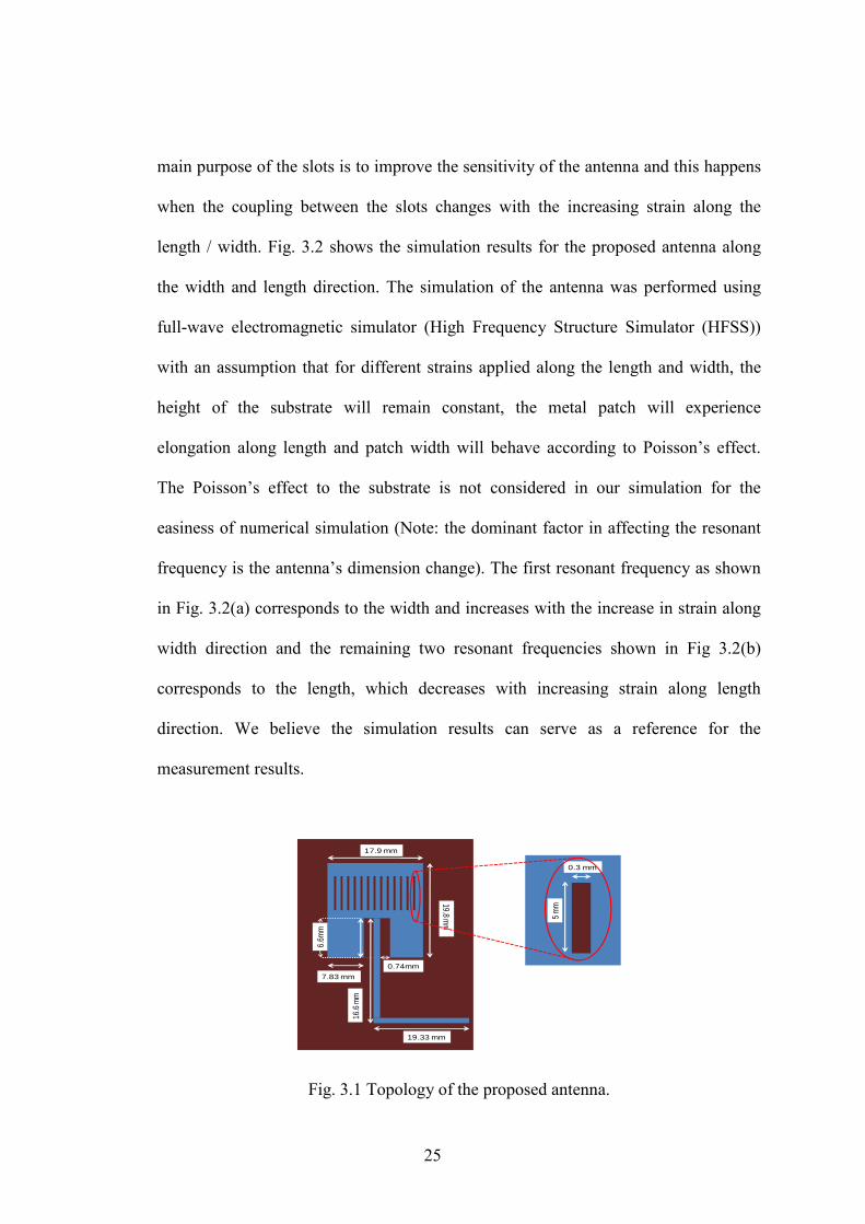
Fig. 3.1 shows the general structure of the antenna. The proposed antenna has
a patch on one side and ground plane on the other side (a microstrip structure) with a
dielectric substrate at the center. This forms an electromagnetic cavity. Due to the
effect of additional slots designed on the antenna, this antenna resonates at multiple
frequencies. There are 13 slots on the patch and the dimension of each slot is 5mm by
0.3mm. The total dimension of the antenna is 19.8mm by 17.9mm. The width of the
feed-line with 50 ohm impedance is calculated to be 0.76mm. This antenna was
designed and fabricated on Rogers’ RT/ duroid 5880 substrate with a substrate
thickness of 0.254mm, dielectric constant of 2.2, and a loss tangent of 0.0009. The
fabrication cost for the antenna is very low compared to the previous strain sensors.
For a simple patch antenna, when a positive strain is applied along the length, the
resonant frequency shifts to a lower value due to the elongation along the length and
when the same strain is applied along the width direction, the resonant frequency
shifts to a higher value due to Poisson’s effect [28]. The relation of the effective
dielectric constant єre with the dielectric constant єr, thickness of the substrate (h) and
the width of the electrical patch (W) can be expressed by the equation
Wh
rrre /1012
12
1+
−++= εεε (1)
From (1), it can be deduced that, with the change in the height of the substrate
and the width of the patch antenna, the effective dielectric constant changes, which
results in the variation of the resonant frequency. The proposed antenna is expected to
behave in a similar manner (since the whole antenna can be thought as a patch). The
24
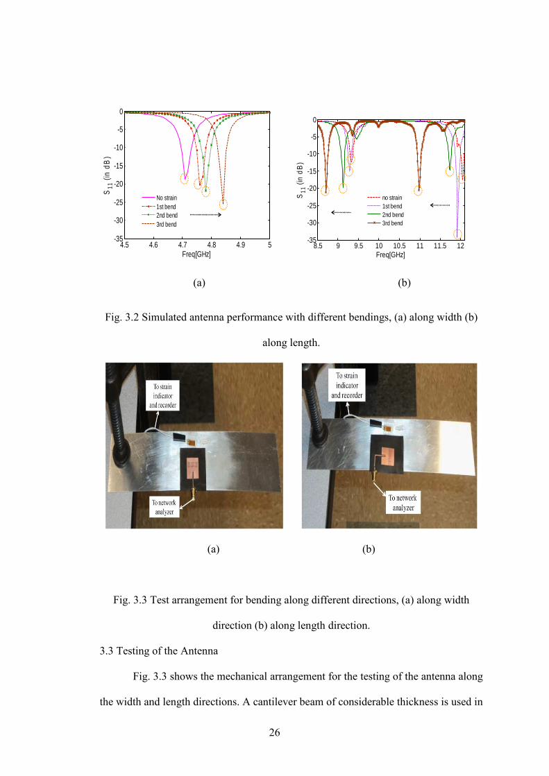
main purpose of the slots is to improve the sensitivity of the antenna and this happens
when the coupling between the slots changes with the increasing strain along the
length / width. Fig. 3.2 shows the simulation results for the proposed antenna along
the width and length direction. The simulation of the antenna was performed using
full-wave electromagnetic simulator (High Frequency Structure Simulator (HFSS))
with an assumption that for different strains applied along the length and width, the
height of the substrate will remain constant, the metal patch will experience
elongation along length and patch width will behave according to Poisson’s effect.
The Poisson’s effect to the substrate is not considered in our simulation for the
easiness of numerical simulation (Note: the dominant factor in affecting the resonant
frequency is the antenna’s dimension change). The first resonant frequency as shown
in Fig. 3.2(a) corresponds to the width and increases with the increase in strain along
width direction and the remaining two resonant frequencies shown in Fig 3.2(b)
corresponds to the length, which decreases with increasing strain along length
direction. We believe the simulation results can serve as a reference for the
measurement results.
0.3 mm
5 m
m19.8 mm
16.6
mm
19.33 mm
7.83 mm
17.9 mm
6.6m
m
0.74mm
Fig. 3.1 Topology of the proposed antenna.
25
4.5 4.6 4.7 4.8 4.9 5-35
-30
-25
-20
-15
-10
-5
0
Freq[GHz]
S11
(in
dB
)
No strain1st bend2nd bend3rd bend
8.5 9 9.5 10 10.5 11 11.5 12
-35
-30
-25
-20
-15
-10
-5
0
Freq[GHz]
S11
(in
dB
)
no strain1st bend2nd bend3rd bend
(a) (b)
Fig. 3.2 Simulated antenna performance with different bendings, (a) along width (b)
along length.
(a) (b)
Fig. 3.3 Test arrangement for bending along different directions, (a) along width
direction (b) along length direction.
3.3 Testing of the Antenna
Fig. 3.3 shows the mechanical arrangement for the testing of the antenna along
the width and length directions. A cantilever beam of considerable thickness is used in
26

order to provide more sensitivity when a small load is applied. M-bond 200 adhesive
was used to attach the antenna and the metal foil strain gauge to the metal beam.
Strain gauge is connected to a strain indicator and recorder which give an
approximate value of strain experienced for each increment of the load. Antenna is
fed by the vector network analyzer through an SMA connector. The measured antenna
performance (S11) is collected in this way. Care should be taken to make sure that a
good solder is provided for the connection between the SMA connector and the
feeding stripline so that the electrical connection between them remains stable even
when the structure experiences different bends. As it can be observed from Fig. 3.3,
the two antennas have different feed-lines (non-folded and folded), which makes the
measurement easier for different directions.
3.4 Measured Results
The measured results are presented in Fig. 3.4 for different strain applied
along the width and length directions. From the measured results as shown in Fig.
3.4(a), it can be concluded that the first resonant frequency which occurs at 5.07 GHz
(without any bend) corresponds to the width and will move to a higher value as the
value of the strain along width increases. The three successive bends caused by the
increasing strain shift the resonant frequency from 5.07 GHz to 5.53GHz, 5.54 GHz
and 5.56 GHz respectively. The remaining two resonant frequencies which occur at
9.27 GHz and 9.93 GHz (without any bend), shown in the Fig. 3.4(b) corresponds to
the length and moves to a lower value when the strain applied along the length is
increased. Table 3.1 gives the value of the strain obtained for each bending state with
different load and Table 3.2 gives the frequency changes obtained for different bends
27
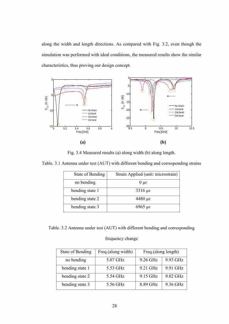
along the width and length directions. As compared with Fig. 3.2, even though the
simulation was performed with ideal conditions, the measured results show the similar
characteristics, thus proving our design concept.
5 5.2 5.4 5.6 5.8 6-15
-10
-5
0
S11
(in
dB
)
Freq [GHz]
No Strain1st bend2nd bend3rd bend
8.5 9 9.5 10 10.5
-30
-25
-20
-15
-10
-5
0
S11
(in
dB
)
Freq [GHz]
No Strain1st bend2nd bend3rd bend
(a) (b)
Fig. 3.4 Measured results (a) along width (b) along length.
Table. 3.1 Antenna under test (AUT) with different bending and corresponding strains
State of Bending Strain Applied (unit: microstrain)
no bending 0 µє
bending state 1 3316 µє
bending state 2 4480 µє
bending state 3 6965 µє
Table. 3.2 Antenna under test (AUT) with different bending and corresponding
frequency change
State of Bending Freq.(along width) Freq.(along length)
no bending 5.07 GHz 9.26 GHz 9.93 GHz
bending state 1 5.53 GHz 9.21 GHz 9.91 GHz
bending state 2 5.54 GHz 9.15 GHz 9.82 GHz
bending state 3 5.56 GHz 8.89 GHz 9.36 GHz
28

3.5 Motivation for Temperature Sensing Antenna
A temperature sensor is a device used to predict accurate temperature for any
source and converts it to a form easily understood by any observer or another
device. Temperature sensors come in many different forms and are used for a wide
variety of purposes such as detecting the temperature change from simple home to the
change of temperature at extremely dangerous furnaces where the interference of
humans is impossible.
Several sensors have been used in the past. Thermocouples form the simple
sensor with complex function [29-30]. A thermocouple consists of two dissimilar
metals, joined together at one end, and produces a small unique voltage at a given
temperature. The thermocouples work on the principle of Thermocouple effect, where
one junction of the thermocouple is the sensing element and the other junction is set at
reference temperature. However, the measurement is complex with potential sources
of error.
Resistivity of metals is highly influenced by the temperature and this led to
resistance temperature detectors (RTDs). But, they suffer from low sensitivity, higher
cost than thermo couples and affected by shock and vibration.
A significant amount of research has been contributed to the development
semiconductor temperature sensors. These sensors are small, accurate and
inexpensive but the use is limited to applications where temperature range is only a
few hundred degrees (generally <150 degrees). However, capacitively loaded MEMS
sensors have been developed which can sense up to a temperature of 3000C [31].
In this chapter, a simple slot antenna is presented which can sense the
temperature greater than 10000C, thus eliminating the drawbacks of the previous
29

sensors. Since the antenna has no additional elements, it doesn’t need calibration,
never wear out and can work under any environmental conditions apart from being
inexpensive and easy to use. The antenna performance is simulated by the full-wave
electromagnetic simulator.
3.6 Antenna Principle, Design and Simulated Results
This antenna works on the following principle. As the temperature increases,
the dielectric constant of the substrate decreases and this shifts the resonant frequency
of the antenna to a higher value. In this configuration, when an incident wave hits the
surface of the antenna, then the reflected wave will be shifted in frequency according
to the change in the temperature, thus giving us the advantage of remotely probing the
antenna from a distance. Fig. 3.5 shows the general structure of the antenna. The
proposed antenna has a ground plane with a slot and this is fed by a magnetically
coupled transmission line of 50 ohm impedance. The width of the transmission line is
calculated to be 0.1mm. The total dimension of the antenna is 16mm by 18mm and
the dimensions of the slot are 2mm by 12mm. This antenna was designed on Zinc
oxide substrate with a thickness of 0.1mm, dielectric constant of 11 and loss tangent
of 0.02. Fig. 3.6 shows the simulated results of the antenna for different dielectric
constants which can be attributed to different values of temperature (increasing
values).
30

2 mm
12 mm
16 mm
18 mm
Fig. 3.5 Topology of the proposed temperature sensor antenna
1 1.05 1.1 1.15 1.2 1.25
x 1010
-30
-25
-20
-15
-10
-5
0
Frequency
dB S
cale
k=8.5k=9k=9.5k=10k=10.5k=11
Fig. 3.6 Simulated results of the proposed temperature sensor
From the simulated results, it can be concluded that as the temperature
increases, the dielectric constant decreases and the resonant frequency increases, thus
proving the design concept.
31

3.7 Summary
In this chapter, analysis of a slotted patch antenna as a strain measurement
device and its response for different strains along the length and width has been
studied. The proposed patch antenna is more sensitive to strain along the length when
compared with the strain applied along the width. The simulated and the measured
results have been presented, verifying our design concept. In the future, this cable
can be replaced by a receiving antenna (using the antenna’s back-scattering effect),
resulting in a low-cost wireless strain measurement device. Also, a more detailed
analysis is required to further study the relation between shifting of the frequencies
and load applied in order to improve the strain measurement accuracy.
Also, a new slot antenna which can be used as a remote temperature sensor for
very high temperatures (usually >10000C) is presented. The proposed antenna has a
linear frequency change from 11.2GHz to 11.8 GHz. Using the antenna’s back
scattering effect, this antenna can be remotely monitored.
32
CHAPTER 4
CONCLUSION
In this thesis, a detailed discussion of the design of broadband and narrow
band antennas and their applications is presented.
I have presented a new concept for designing a Ultra wideband antenna which
can cover a wide bandwidth, proving that two individual wideband antennas can be
connected together in a way inspired by the log periodic antenna array technique
using a parallel stripline. The UWB antenna covers a wide frequency band
encompassing the bandwidth of the two individual antenna elements. In order to cover
more bandwidth, this UWB antenna was scaled by a factor of 4 and after a lot of
effort involved in optimization of several parameters that were found to have an
adverse effect on the antenna’s performance; a stable bandwidth of 0.66GHz to
120GHz was obtained. This is by far, the largest bandwidth achieved for antenna
based on CRLH metamaterial concept.
Several strain sensors are available in the market for structural health
monitoring (SHM). In chapter 3, I have addressed the issues related to the current
strain sensors came up with a new antenna design concept which can overcome the
drawbacks of the previous sensors. Analysis of a slotted patch antenna as a strain
measurement device and its response for different strains along the length and width
has been studied. During the simulations and testing of the antenna, it was observed
that the proposed patch antenna is more sensitive to strain along the length when
compared with the strain applied along the width. The simulated and the measured
results have been presented, verifying our design concept. For testing the current
33

antenna we have used a cable to probe it but in the future, this cable can be replaced
by a receiving antenna (using the antenna’s back-scattering effect), resulting in a low-
cost wireless strain measurement device. The relation between shifting of the
frequencies and load applied is to be studied in more detail to further improve the
strain measurement accuracy.
We have also presented a simple slot antenna and its application as a
temperature sensor. This antenna can sense very high temperature changes (usually
>10000C), which make it suitable for working under extreme conditions. This antenna
too can be probed wirelessly using the antenna’s backscattering effect which makes it
a brilliant passive temperature sensor.
34

APPENDIX
LIST OF PUBLICATIONS
35

1. Zeeshan Salmani and Hualiang Zhang, “Log-periodic array inspired parallel
strip Ultra Wideband (UWB) antenna”, published in IEEE Radio and Wireless
Symposium (RWS) 2011.
2. Zeeshan Salmani, Yuan Xie, Geng Zheng, Haifeng Zhang, Hualiang Zhang,
“Application of Antenna in Strain Measurement,” published in International
workshop on Antenna Technology (iWAT) 2011.
3. Zeeshan Salmani, and Hualiang Zhang, “Parallel Strip fed Antenna with
extremely wide bandwidth,” (In press) IEEE International Symposium on
Antennas and Propagation (APS) 2011.
36
REFERENCES
[1] D. M. Pozar, “Microstrip antennas,” proc. IEEE, vol. 80, no. 1, pp.79-91, Jan.
1992.
[2] H. Pues, J. Bogaers, R. Pieck, A. Van de capelle, “Wideband quasi-log-
periodic microstrip antenna,” IEE PROC., vol. 128, pp-159-163, June 1981.
[3] H. Ozeki, S. Hayashi, N. Kikuma, and N.Inagaki, “Quasi-log-periodic
microstrip antenna with close coupled elements,” Electrical Engineering, vol.
132, no. 2, pp. 58-64, Japan 2000.
[4] Q. Wu, R. Jin, and J. Geng, “A single-layer ultrawideband microstrip
antenna,” IEEE Trans. on Antennas and propagation, vol. 58, no. 1,pp. 211-
214, Jan. 2010.
[5] H. K. Smith, P. E. Mayes, “Log-periodic array of dual feed microstrip patch
antennas,” IEEE Trans. on Antennas and propagation, vol. 39, no. 12, pp.
1659-1664, Dec. 1991.
[6] W. Huang, N. Xu, V. Pathak, G. Poilasne and M. Achour,
“Composite right-left handed metamaterial ultra wideband antenna,”
International workshop on Antenna Technology (iWAT), Mar. 2009.
[7] W. E. Mckinzie III, J. J. Moncada, and T. L. Anderson, “A microstrip fed log
periodic slot array,” Antennas and propagation society international
symposium, 1994. AP-S. Digest vol. 2, pp. 1278-1281, Jun. 1994.
37

[8] J.Y. Jan and J.-C. Kao, “Novel printed wide-band rhombus like slot antenna
with an offset microstrip fed line,” IEEE Antennas and wireless propagation
letters, vol. 6, pp. 249-251, Jun. 2007.
[9] S. H. Kim, J. H. Choi, J. W. Baik, and Y. S. Kim, “CPW-fed log-periodic
dumb-bell slot antenna array,” IET Electronics letters, vol. 42, no. 8, pp. 436-
438, April 2006.
[10] S.Y. Chen, P.-H. Wang, P. Hsu, “Uniplanar log periodic slot antenna fed by a
CPW for UWB applications,” IEEE Antennas and wireless propagation letters,
vol. 5, no. 1, pp. 256-259, Dec. 2006.
[11] Q. Xue, “Double sided parallel strip line and its applications,” IEEE MTT-S
International Microwave Workshop Series on Art of Miniaturizing RF and
Microwave passive components, Dec. 2008.
[12] S.G. Kim and K. Chang, “Ultra-wideband transitions and new microwave
components using double-sided parallel-strip lines,” IEEE Trans. on Microwave
Theory and Techniques, vol. 52, no. 9, pp. 2148-2152, Sep. 2009.
[13] X.-H. Wang, Q. Xue, W.-W. Choi, “A Novel Ultra-wideband differential filter
based on double sided parallel strip line,” IEEE Microwave and Wireless
Components Letters, 2010.
[14] P. L. Carro, R. Gracia and J. de Mingo, “Parallel-Strip-Fed antenna design in
Ultrawideband applications,” IEEE Antennas and propagation Society
International Symposium, Jun. 2007.
38
[15] N. Li, J. Huang, Q. Hao and Z. Feng, “A parallel strip line center-probe fed
dipole,” APMC 2005 proceedings.
[16] P.L. Carro and J. de Mingo, “Analysis and Synthesis of Double-sided parallel-
strip transitions,” IEEE Trans. on Microwave Theory and Techniques, vol. 58,
no. 2, Feb. 2010.
[17] P. Kulha, A. Boura, and M. Husak, “Design and characterization of NCD
piezoresistive strain sensor,” IEEE International Symposium on Industrial
Eelectronics (ISIE), pp. 121-126, July 2009.
[18] J. Cui, B. Zhang, J. Liu, C. Xue, G. Liu, and X. Jia, “Design of a novel sensor
based on piezo-resistive effect of GaAs/AlGaAs/InGaAs PHEMT,” 4th IEEE
International Conference on Nano/Micro Engineered and Molecular Systems,
pp.1103-1106, Jan. 2009.
[19] S.P. Olson, J. Castracane, and R.E. Spoor, “Piezoresistive strain gauges for
use in wireless component monitoring systems,” IEEE Sensors Applications
Symposium, Feb. 2008.
[20] H.I. Kuo, J. Guo, and W.H. Ko, “High performance piezoresistive micro strain
sensors,” proceedings of 2nd IEEE International Conference on Nano/Micro
Engineered and Molecular Systems, Jan. 2007.
[21] A.W. Domanski, “Application of optical fiber sensors in mechanical
measurements,” IEEE Instrumentation and Measurement Technology
Conference, May 1997.
39

[22] A. Martin, R. Badcock, C. Nightingale, and G.F. Fernando, “A novel optical
fiber based strain sensor,” IEEE Photonics Technology Letters, vol. 9, no. 7, July
1997.
[23] T. Abe, Y. Mitsunaga, and H. Koga, “A strain sensor using twisted optical
fibers,” Journal of Lightwave Technology, vol. 7, no. 3, Mar. 1989.
[24] G. Fernando, D.J. Webb, and P. Ferdinand, Guest Editors, “Optical fiber
sensors,” Materials Research Society Bulletin, May 2002.
[25] N. Chaimanonart, and D.J. Young, “Remote RF powering system for wireless
MEMS strain sensors,” IEEE Sensors Journal, vol. 6, no. 2, April 2006.
[26] E.L. Tan, B.D. Pereles, R. Shao, J. Ong, and K.G. Ong, “A wireless passive
strain sensor based on the harmonic response of magnetically soft materials,”
Smart Materials and Structures, vol. 17, no. 2, 2008.
[27] V. Kalinin, “Passive wireless strain and temperature sensors based on SAW
devices,” IEEE Radio and Wireless Conference, pp. 187-190, Sept. 2004.
[28] U. Tata, H. Huang, R.L. Carter, and J.C. Chiao, “Exploiting a patch antenna
for strain measurements,” Measurement Science and Technology, vol. 20, no. 1,
Jan. 2009.
[29] T .J .Bajzek , “Thermocouples: A Sensor for Measuring Temperature,” IEEE
Instrumentation & Measurement Magazine, vol. 8, no. 1, pp. 35-40, 2005.
[30] M. Zhang, “Research and Implement of thermocouple sensor and
microcontroller interface,” International conference on multimedia technology,
pp.1-3, 2010.
40

[31] S. Scott, D. Peroulis, “A capacitively-loaded MEMS slot element for wireless
temperature sensing of upto 3000C,” IEEE microwave symposium digest, pp.
1161-1164, 2009.
41