design and implementation of driver gaze tracking...
TRANSCRIPT
WWW.IJITECH.ORG
ISSN 2321-8665
Vol.04,Issue.03,
March-2016,
Pages:0493-0501
Copyright @ 2016 IJIT. All rights reserved.
Design and Implementation of Driver Gaze Tracking System PAPAGANTI KEERTHI
1, GALAM HANUMANTH RAO
2, THADAPUNENI TRIVENI
3, MALLEMPUDI GOPINATH
4
1Gandhiji Institute of Science and Technology, Gattubhimavaram, AP, India, E-mail: [email protected].
2Gandhiji Institute of Science and Technology, Gattubhimavaram, AP, India, E-mail: [email protected].
3Gandhiji Institute of Science and Technology, Gattubhimavaram, AP, India, E-mail: [email protected].
4Gandhiji Institute of Science and Technology, Gattubhimavaram, AP, India, E-mail: [email protected].
Abstract: Distracted Driving Is One Of The Main Causes Of
Vehicle Collisions in the United States. Passively Monitoring
a Driver’s Activities Constitutes the Basis of an Automobile
Safety System That Can Potentially Reduce the Number of
Accidents by Estimating the Driver’s Focus Of Attention.
This Paper_Proposes_An_Inexpensive_Vision-Based System
to Accurately Detect Eyes off the Road (EOR).The System
Has Three Main Components: 1) Robust Facial Feature
Tracking; 2) Head Pose And Gaze Estimation; And 3) 3-D
Geometric Reasoning To Detect EOR. From The Video
Stream Of A Camera Installed On The Steering Wheel
Column, Our System Tracks Facial Features From The
Driver’s Face. Using The Tracked Landmarks And A 3-D
Face Model, The System Computes Head Pose And Gaze
Direction. The Head Pose Estimation Algorithm Is Robust To
Nonridged Face Deformations Due To Changes In
Expressions. Finally, Using 3-D Geometric Analysis, The
System Reliably Detects EOR. The Proposed System Does
Not Require Any Driver-Dependent Calibration Or Manual
Initialization And Works In Real Time (25 FPS), During The
Day And Night. To Validate The Performance Of The System
In A Real Car Environment,We Conducted A Comprehensive
Experimental Evaluation Under A Wide Variety Illumination
Conditions, Facial Expressions, And Individuals. Our System
Achieved Above 90% EOR Accuracy For All Tested
Scenarios.
Keywords: Driver Monitoring System, Gaze Estimation,
Head Pose Estimation.
I. INTRODUCTION
DRIVER Distractions Are The Leading Cause Of Most
Vehicle Crashes And Near-Crashes. According To A Study
Released By The National Highway Traffic Safety
Administration(NHTSA) &The Virginia Tech Transportation
Institute (VTTI) [16], 80% Of Crashes And 65% Of Near-
Crashes Involve Some Form Of Driver Distraction. In
Addition, Distractions Typically Occurred Within Three
Seconds Before The Vehicle Crash.Recent Reports Have
Shown That From 2011 To 2012, The Number Of People
Injured In Vehicle Crashes Related To Distracted Driving Has
Increased 9% [1]. In 2012 Alone, 3328 People Were Killed
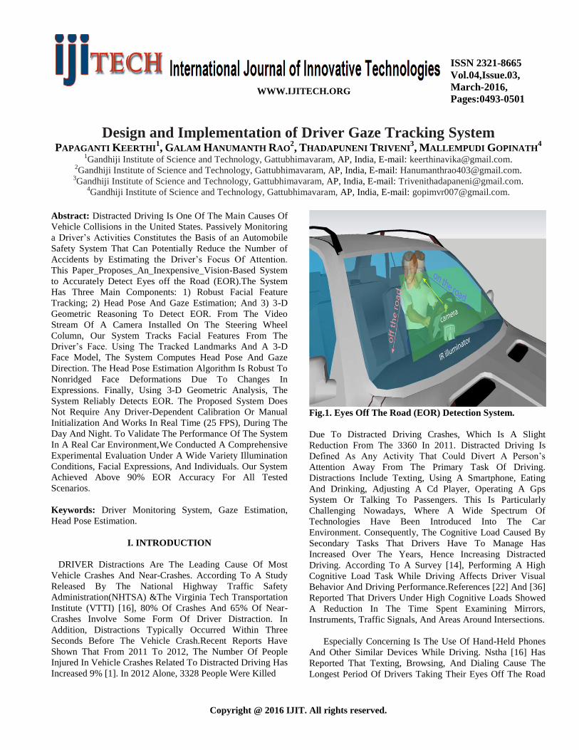
Fig.1. Eyes Off The Road (EOR) Detection System.
Due To Distracted Driving Crashes, Which Is A Slight
Reduction From The 3360 In 2011. Distracted Driving Is
Defined As Any Activity That Could Divert A Person’s
Attention Away From The Primary Task Of Driving.
Distractions Include Texting, Using A Smartphone, Eating
And Drinking, Adjusting A Cd Player, Operating A Gps
System Or Talking To Passengers. This Is Particularly
Challenging Nowadays, Where A Wide Spectrum Of
Technologies Have Been Introduced Into The Car
Environment. Consequently, The Cognitive Load Caused By
Secondary Tasks That Drivers Have To Manage Has
Increased Over The Years, Hence Increasing Distracted
Driving. According To A Survey [14], Performing A High
Cognitive Load Task While Driving Affects Driver Visual
Behavior And Driving Performance.References [22] And [36]
Reported That Drivers Under High Cognitive Loads Showed
A Reduction In The Time Spent Examining Mirrors,
Instruments, Traffic Signals, And Areas Around Intersections.
Especially Concerning Is The Use Of Hand-Held Phones
And Other Similar Devices While Driving. Nstha [16] Has
Reported That Texting, Browsing, And Dialing Cause The
Longest Period Of Drivers Taking Their Eyes Off The Road
PAPAGANTI KEERTHI, GALAM HANUMANTH RAO, THADAPUNENI TRIVENI, MALLEMPUDI GOPINATH
International Journal of Innovative Technologies
Volume.04, Issue No.03, March-2016, Pages: 0493-0501
(Eor) And Increase The Risk Of Crashing By Three Fold. A
Recent Study [41] Shows That These Dangerous Behaviors
Are Wide-Spread Among Drivers, 54% Of Motor Vehicle
Drivers In The United States Usually Have A Cell Phone In
Their Vehicles Or Carry Cell Phones When They Drive.
Monitoring Driver Activities Forms The Basis Of A Safety
System That Can Potentially Reduce The Number Of Crashes
By Detecting Anomalous Situations. In [29], Authors Showed
That A Successful Vision-Based Distracted Driving Detection
System Is Built Upon Reliable Eor Estimation, See Fig1.
However, Building A Realtime Eor Detection System For
Real Driving Scenarios Is Very Challenging For Several
Reasons: (1) The System Must Operate During The Day And
Night And Under Real World Illumination Conditions; (2)
Changes In Drivers’ Head Pose And Eye Movements. Result
In Drastic Changes In The Facial Features (E.G., Pupil And
Eye Corners) To Be Tracked; (3) The System Must Be
Accurate For A Variety Of People Across Multiple
Ethnicities, Genders, And Age Ranges. Moreover, It Must Be
Robust To People With Different Types Of Glasses. To
Address These Issues, This Paper Presents A Low-Cost,
Accurate, And Real-Time System To Detect Eor. Note That
Eor Detection Is Only One Component Of A System For
Detecting And Alerting Distracted Drivers.
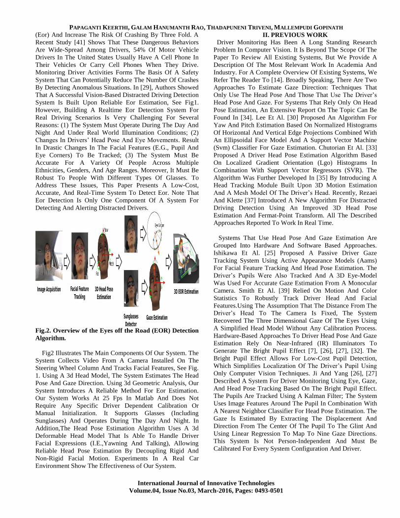
Fig.2. Overview of the Eyes off the Road (EOR) Detection
Algorithm.
Fig2 Illustrates The Main Components Of Our System. The
System Collects Video From A Camera Installed On The
Steering Wheel Column And Tracks Facial Features, See Fig.
1. Using A 3d Head Model, The System Estimates The Head
Pose And Gaze Direction. Using 3d Geometric Analysis, Our
System Introduces A Reliable Method For Eor Estimation.
Our System Works At 25 Fps In Matlab And Does Not
Require Any Specific Driver Dependent Calibration Or
Manual Initialization. It Supports Glasses (Including
Sunglasses) And Operates During The Day And Night. In
Addition,The Head Pose Estimation Algorithm Uses A 3d
Deformable Head Model That Is Able To Handle Driver
Facial Expressions (I.E.,Yawning And Talking), Allowing
Reliable Head Pose Estimation By Decoupling Rigid And
Non-Rigid Facial Motion. Experiments In A Real Car
Environment Show The Effectiveness of Our System.
II. PREVIOUS WORK
Driver Monitoring Has Been A Long Standing Research
Problem In Computer Vision. It Is Beyond The Scope Of The
Paper To Review All Existing Systems, But We Provide A
Description Of The Most Relevant Work In Academia And
Industry. For A Complete Overview Of Existing Systems, We
Refer The Reader To [14]. Broadly Speaking, There Are Two
Approaches To Estimate Gaze Direction: Techniques That
Only Use The Head Pose And Those That Use The Driver’s
Head Pose And Gaze. For Systems That Rely Only On Head
Pose Estimation, An Extensive Report On The Topic Can Be
Found In [34]. Lee Et Al. [30] Proposed An Algorithm For
Yaw And Pitch Estimation Based On Normalized Histograms
Of Horizontal And Vertical Edge Projections Combined With
An Ellipsoidal Face Model And A Support Vector Machine
(Svm) Classifier For Gaze Estimation. Chutorian Et Al. [33]
Proposed A Driver Head Pose Estimation Algorithm Based
On Localized Gradient Orientation (Lgo) Histograms In
Combination With Support Vector Regressors (SVR). The
Algorithm Was Further Developed In [35] By Introducing A
Head Tracking Module Built Upon 3D Motion Estimation
And A Mesh Model Of The Driver’s Head. Recently, Rezaei
And Klette [37] Introduced A New Algorithm For Distracted
Driving Detection Using An Improved 3D Head Pose
Estimation And Fermat-Point Transform. All The Described
Approaches Reported To Work In Real Time.
Systems That Use Head Pose And Gaze Estimation Are
Grouped Into Hardware And Software Based Approaches.
Ishikawa Et Al. [25] Proposed A Passive Driver Gaze
Tracking System Using Active Appearance Models (Aams)
For Facial Feature Tracking And Head Pose Estimation. The
Driver’s Pupils Were Also Tracked And A 3D Eye-Model
Was Used For Accurate Gaze Estimation From A Monocular
Camera. Smith Et Al. [39] Relied On Motion And Color
Statistics To Robustly Track Driver Head And Facial
Features.Using The Assumption That The Distance From The
Driver’s Head To The Camera Is Fixed, The System
Recovered The Three Dimensional Gaze Of The Eyes Using
A Simplified Head Model Without Any Calibration Process.
Hardware-Based Approaches To Driver Head Pose And Gaze
Estimation Rely On Near-Infrared (IR) Illuminators To
Generate The Bright Pupil Effect [7], [26], [27], [32]. The
Bright Pupil Effect Allows For Low-Cost Pupil Detection,
Which Simplifies Localization Of The Driver’s Pupil Using
Only Computer Vision Techniques. Ji And Yang [26], [27]
Described A System For Driver Monitoring Using Eye, Gaze,
And Head Pose Tracking Based On The Bright Pupil Effect.
The Pupils Are Tracked Using A Kalman Filter; The System
Uses Image Features Around The Pupil In Combination With
A Nearest Neighbor Classifier For Head Pose Estimation. The
Gaze Is Estimated By Extracting The Displacement And
Direction From The Center Of The Pupil To The Glint And
Using Linear Regression To Map To Nine Gaze Directions.
This System Is Not Person-Independent And Must Be
Calibrated For Every System Configuration And Driver.

Design and Implementation of Driver Gaze Tracking System
International Journal of Innovative Technologies
Volume.04, Issue No.03, March-2016, Pages: 0493-0501
Batista [7] Used A Similar System But Provided A More
Accurate Gaze Estimation Using Ellipse Fitting For The Face
Orientation. These Near-IR Illumination Systems Work
Particularly Well At Night, But Performance Can Drop
Dramatically Due To Contamination Introduced By External
Light Sources And Glasses[8],[21]. While The Contamination
Due To Artificial Lights Can Easily Be Filtered With A
Narrow Band Pass Filter, Sunlight Contamination Will Still
Exist. Additionally, The Hardware Necessary To Generate
The Bright Eye Effect Will Hinder System Integration Into
The Car Dashboard. In Industry, Systems Based On Near-IR
Are The Most Common.The Saab Driver Attention Warning
System [6] Detects Visual Inattention And Drowsy Driving.
The System Uses Two Miniature IR Cameras Integrated With
Smart Eye Technology to Accurately
Fig.3. Camera And IR Illuminator Position.
Estimate Head Pose, Gaze, And Eyelid Status. When A
Driver’s Gaze Is Not Located Inside The Primary Attention
Zone (Which Covers The Central Part Of The Frontal
Windshield) For A Predefined Period, An Alarm Is Triggered.
Nevertheless, No Further Details About The Performance Of
The System In Real Driving Scenarios Were Reported.
Toyota Has Equipped Their High-End Lexus Models With
Their Driver Monitoring System [24]. The System
Permanently Monitors The Movement Of The Driver’s Head
When Looking From Side To Side Using A Near-Ir Camera
Installed On The Top Of The Steering Wheel Column. The
System Is Integrated Into Toyota’s Pre-Crash System, Which
Warns The Driver When A Collision Is Probable. Another
Commercial System Is Facelab [2], A Stereo-Based Eye
Tracker That Detects Eye Movement, Head Position And
Rotation,Eyelid Aperture And Pupil Size. Facelab Uses A
Passive Pair Of Stereo Cameras Mounted On The Car
Dashboard. The System Has Been Used In Several Driver
Assistance And Inattention Systems, Such As [17]–[19].
However, Stereo-Based Systems Are Too Expensive To Be
Installed In Mass-Produced Cars And They Require Periodic
Re-Calibration Because Vibrations Cause The System
Calibration To Drift Over Time. Similarly, Smart Eye [3]
Uses A Multicamera System That Generates 3d Models Of
The Driver’s Head, Allowing It To Compute Her Gaze
Direction,Head Pose, And Eyelid Status. This System Has
Been Evaluated In [5]. Unfortunately, It Is Prohibitively
Expensive For Mass Dissemination In Commercial Cars And
It Imposes Strong Constraints With Respect To The
Necessary Hardware To Be Installed.As A Result, It Is
Unfeasible To Install This System In Regular Cars. Other
Commercial Systems Include The Ones Developed By Delphi
Electronics [15] And Sensomotoric Instruments GmbH [4].
III. SYSTEM DESCRIPTION
This Section Describes The Main Components Of Our
System. There Are Six Main Modules: Image Acquisition,
Facial Feature Detection And Tracking, Head Pose
Estimation, Gaze Estimation, Eor Detection, And Sunglasses
Detection. Fig. 2 Shows The System Block Diagram And
Algorithm Flow.
A. Image Acquisition
The Image Acquisition Module Is Based On A Low-Cost
CCD Camera (In Our Case, A Logitech C920 Webcam)
Placed On Top of the Steering Wheel Column, See Fig. 3.
The CCD Camera Was Placed Over The Steering Wheel
Column For Two Reasons :(1) It Facilitates The Estimation
Of Gaze Angles, Such As Pitch,Which Is Relevant For
Detecting When The Driver Is Texting On A Phone (A Major
Threat To Safety). (2) From A Production Point Of View, It Is
Convenient To Integrate A CCD Camera Into The Dashboard.
On The Downside, When the Wheel Is Turning There Will Be
Some Frames in Which the Driver’s Face Will Be occluded
By the Steering Wheel.
Fig. 4. A) Mean Landmarks, X0, Initialized Using The
Face Detector. Black Outline Indicates Face Detector. B)
Manually Labeled Image With 51 Landmarks.
For Night Time Operation, the System Requires An
Illumination Source To Provide A Clear Image Of The
Driver’s Face. Moreover, The Illumination System Cannot
Impact The Driver’s Vision. To This End, An IR Illuminator
Was Installed On The Car Dashboard, See Fig. 3. Note That
The Proposed System Does Not Suffer From The Common
Drawbacks Of Near-IR Based Systems [7], [26],[27], Because
It Does Not Rely On The Bright Pupil Effect. To Adapt Our

PAPAGANTI KEERTHI, GALAM HANUMANTH RAO, THADAPUNENI TRIVENI, MALLEMPUDI GOPINATH
International Journal of Innovative Technologies
Volume.04, Issue No.03, March-2016, Pages: 0493-0501
CCD Camera To IR Illumination, It Was Necessary To
Remove The IR Filter From The CCD Camera, Making The
CCD More Sensitive To IR Illumination (I.E., Sunlight,
Artificial Illumination). As Shown In Fig. 5, This Effect Is
Not Noticeable In Real Driving Scenarios.
B. Facial Feature Detection and Tracking
Parameterized Appearance Models (Pams), Such As Active
Appearance Models (E.G., [12], [13]) And Morphable Models
[9], Are Popular Statistical Techniques For Face Tracking.
They Build An Object Appearance And Shape Representation
By Computing Principal Component Analysis (PCA) On A
Set Of Manually Labeled Data. Fig. 4(A) Illustrates An Image
Labeled With P Landmarks (P = 51 In This Case). Our Model
Includes Two Extra Landmarks For The Center Of The
Pupils. However, There Are Several Limitations Of Pams
That Prevent To Use Them For Detection And Tracking In
Our System. First, Pams Typically Optimize Many
Parameters (About 50–60), Which Makes Them Very Prone
To Local Minima. Second, Pams Work Very Well For
Person-Specific Subjects But Do Not Generalize Well To
Other Untrained Subjects Because They Use A Linear Model
Of Shape And Appearance [13]. Third, The Shape Model
Typically Cannot Model Asymmetric Expressions (E.G., One
Eye Open And Another Closed,Or An Asymmetric Smile).
This Is Due To The Fact That In Most Training Datasets,
These Expressions Do Not Occur.To Address The Limitations
Of Pams, Xiong And De La Torre Proposed The Supervised
Descent Method (SDM) [44], Which Is A Discriminative
Method For Fitting Pams. There Are Two Main Differences
From The Traditional Pams. First, It Uses A Non-Parametric
Shape Model That Is Better Able To Generalize To Untrained
Situations (E.G., Asymmetric Facial Gestures). Second,Sdm
Uses A More Complex Representation (Sift Descriptor [31]
Around The Landmarks). This Provides A More Robust
Representation Against Illumination, Which Is Crucial For
Detecting And Tracking Faces In Driving Scenarios.
Given An Image D ∈ Rm×1 Of M Pixels, D(X) ∈ Rp×1 (See
Footnote For Notation)1 Indexes P Landmarks In The Image.
H Is A Non-Linear Feature Extraction Function (In Our Case
Sift Features) And H(D(X)) ∈ R128p×1 Because Sift Features
Have 128 Dimensions. During Training, We Will Assume
That The Correct P Landmarks Are Known, And We Will
Refer To Them As X∗ [See Fig. 4(B)]. Also, To Reproduce
The Testing Scenario, We Ran The Face Detector On The
Training Images To Provide An Initial Configuration Of The
Landmarks (X0), Which Corresponds To An Average Shape
[See Fig. 4(A)]. Then, Face Alignment Can Be Formulated
As Minimizing The Following Function Over Δx
(1)
Where Φ∗ = H(D(X∗)) Represents The SIFT Values In The
Manually Labeled Landmarks. In The Training Images, Φ∗
And Δx Are Known.
One Could Use Newton’s Method To Minimize Eq.
(1).Newton’s Method Makes The Assumption That A Smooth
Function,F(X), Can Be Well Approximated By A Quadratic
Function In A Neighborhood Of The Minimum. If The
Hessian Is Positive Definite,The Minimum Can Be Found By
Solving A System Of Linear Equations. The Newton Updates
To Minimize Eq. (1) Would Be:
(2)
Where Φk−1 = H(D(Xk−1)) Is The Feature Vector Extracted
At The Previous Set Of Landmark Locations, Xk−1, H And
Jh Are The Hessian And Jacobian Evaluated At Xk−1. Note
That The Sift Operator Is Not Differentiable And Minimizing
Eq(1) Using First Or Second Order Methods Requires
Numerical Approximations (E.G.,Finite Differences) Of The
Jacobian And The Hessian. However, Numerical
Approximations Are Very Computationally Expensive.
Furthermore, Φ∗ Is Known In Training But Unknown In
Testing. Sdm Addresses These Issues By Learning A Series
Of Descent Directions And Re-Scaling Factors (Done By The
Hessian In The Case Of Newton’s Method) Such That It
Produces A Sequence Of Updates (Xk+1 = Xk +Δxk) Starting
From X0 That Converges To X∗ In The Training Data. That
Is, Sdm Learns From Training Data A Sequence Of Generic
Descent Directions {Rk} And Bias Terms {Bk}
(3)
Such That The Succession Of Xk Converges To X∗ For All
Images In The Training Set. For More Details On Sdm, See
[44].
Fig.5. SDM Landmark Detection Under Different Poses,
Illuminations, And Ethnicities.
C. Head Pose Estimation
In Real Driving Scenarios, Drivers Change Their Head Pose
And Facial Expression While Driving. Accurately Estimating
Driver’s Head Pose In Complex Situations Is A Challenging
Problem. In This Section, A 3D Head Pose Estimation System
Is Proposed To Decouple Rigid And Non-Rigid Head Motion.
The Head Model Is Represented Using A Shape Vector, Q
∈R(3·49×1), Concatenating The X, Y, Z Coordinates Of All
Vertices. The Deformable Face Model Is Constructed By
Computing PCA [9] On The Training Dataset From Cao Et

Design and Implementation of Driver Gaze Tracking System
International Journal of Innovative Technologies
Volume.04, Issue No.03, March-2016, Pages: 0493-0501
Al. [10], Which Contains Aligned 3D Face Shapes That Have
Variation In Both Identity And Expression. A New 3D Shape
Can Be Reconstructed As A Linear Combination of
Eigenvectors Vi And The Mean Shape Q
(4)
Given 49 Tracked 2D Facial Landmarks (Pk ∈ R2×1, K =
1, . . . , 49, Excluding The Pupil Points) From The
Sdmtracker, We Simultaneously Fit The Head Shape And
Head Pose By Minimizing The Difference Between The 2D
Landmarks And The Projection Of The Corresponding 3D
Points From The Model. In This Paper,We Assume A Weak-
Perspective Camera Model [43], Also Called Scaled
Orthographic Projection. The Fitting Error Is Defined As
(5)
Where K Is The Index Of The K-Th Facial Landmark, P ∈
R2×3 Is A Projection Matrix, Lk ∈ R3×(3·49) Is The
Selection Matrix That Selects The Vertex Corresponding To
The K-Th Facial Landmark, R ∈ R3×3 Is A Rotation Matrix
Defined By The Head Pose Angles,T_Headp ∈ R3×1 Is A 3D
Translational Vector Of The Driver’s Head Relative To The
Camera’s Optical Center, And S Is A Scale Factor
Approximating The Perspective Image Formation. The
Overall Fitting Error, E, Which Is The Total Fitting Error Of
All Landmarks,
Fig.6. Examples Of 3D Reconstruction And Head Pose
Estimation In The Car Environment.
Is Minimized With Respect To The Pose Parameters (R,
T_Headp, S) And Shape Coefficients, Β, Using An
Alternating Optimization Approach. We Alternate Between
The Estimation Of The Rigid Parameters, R And S, And The
Non-Rigid Parameter Β. These Steps Monotonically Reduce
The Fitting Error E, And Because The Function Is Bounded
Below, We Converge To A Critical Point, See [45]. Fig. 6
Shows Four Examples Of The Head Pose Estimation And 3D
Head Reconstruction. Translation Mapping: In The Method
Described Above, The Head Translation Vector, T_Headp, Is
Computed In Pixels. To Compute the EOR Estimation Using
The Geometry Of The Scene, We Need To Map Pixels To
Centimeters, Obtaining The Vector T_Head. This Mapping Is
Performed Using A Data-Driven Approach. For A Fixed
Focal Length, We Collected A Set Of Translation Vectors In
Pixels And Their Corresponding Real Length In Centimeters.
A Linear System Is Solved To Obtain the Unit Mapping
(6)
Where A ∈ R3×3
And B ∈ R3×1
Are Linear Coefficients To
Solve.It Is Worth Noting That This Affine Mapping Was
Done Outside The Car Environment And Generalized Well
For Several Cameras Of The Same Model (Logitech C920).
Angular Compensation: As Stated Above, The Head Pose
Estimation Algorithm Is Based On The Weak-Perspective
Assumption,Hence We Use A Scaled Orthographic
Projection. This Assumption Is Accurate When The Driver’s
Head Is Near The Visual Axis Of The Camera. However, In
The Car Scenario, Due To Several Factors,Such As The
Driver’s Height, Seating Position, And The Fixed Tilt Of The
Camera, The Driver’s Head May Not Always Be Close To
The Visual Axis. Fig. 7 Shows Three Different Positions Of
The Driver’s Head And Their Corresponding Images
Generated By The Camera, Produced By A Perspective
Projection, And A Scaled Orthographic Projection,
Respectively. As We Can See, The Camera View And The
Scaled Orthographic Projection Image Match In The Position
B, Where The Driver’s Head Is Aligned With The Camera
Visual Axis.For Positions A And C, Camera Images And
Weak Perspective Images Differ Due To A Translation With
Respect To The Camera Visual Axis. As A Result, The Head
Pose Estimation Algorithm Will Introduce An Offset Caused
By The Driver’s Head Position. To Correct This Offset, It Is
Necessary To Introduce A Heuristic
Fig.7. Difference Between Camera Image And Weak
Perspective Projection Image Caused By Translation Of
The Driver’s Head With Respect The Camera Virtual
Axis. Top Row (Ac, Bc, And Cc) Shows The Different
Images Generated In The Camera For Positions A, B, C.
Bottom Row Shows The Weak Perspective Projection
Images Using The Same Translations. When The Face Is
Near The Visual Axis (Blue Rectangle), The Weak
Perspective Projection Image Is Similar To The Real
Image Captured By The Camera. When The Face Is Off
The Visual Axis, There Will Be Discrepancy Between
These Two Images.
PAPAGANTI KEERTHI, GALAM HANUMANTH RAO, THADAPUNENI TRIVENI, MALLEMPUDI GOPINATH
International Journal of Innovative Technologies
Volume.04, Issue No.03, March-2016, Pages: 0493-0501
Compensation for The Head Rotation. Fig. 7 Shows The
Heuristic Compensation Computed For A Lateral Translation
That Affects The Estimation Of The Yaw Angle. A Similar
Compensation Is Computed For The Pitch Angle For A
Vertical Translation. As A Result, The Yaw And Pith Angles
Estimated By Our Head Pose Algorithm In The Car
Environment Are Given By
(7)
(8)
Where Yyaw And Ypitch Are The Original Yaw And Pitch
Angles Computed By Our Algorithm, And yaw And pitch
Are The Corresponding Compensation Angles. Note That No
Compensation Was Introduced For The Roll Angle, Our Tests
Showed That The Roll Angle Was Less Sensitive To
Translations With Respect To The Camera Virtual Axis.
D. Gaze Estimation
The driver’s gaze direction provides crucial information as
to whether the driver is distracted or not. Gaze estimation has
been a long standing problem in computer vision [23],
[25].Most existing work follows a model-based approach to
gaze estimation that assumes a 3D eye model, where the eye
center is the origin of the gaze ray. In this paper, we used a
similar model (see Fig. 8). We make three main assumptions:
First, the eyeball is spherical and thus the eye center is at a
fixed point (rigid point) relative to the head model; Second,
all the eye points, including the pupil, are detected using the
SDM tracker described in the previous section. Note that
more accurate pupil center estimates are possible using other
techniques such as the Hough transform; Third, the eye is
open and therefore all the eye contour points can be
considered rigid. Our algorithm has two main parts: (1)
Estimate the 3D position of the pupil from the rigid eye
contour points, and (2) estimate the 3D gaze direction from
the pupil position and the eye center.The 3D position of the
pupil is computed as follows:1) Triangulate the eye contour
points in 2D and determine which triangle mesh contains the
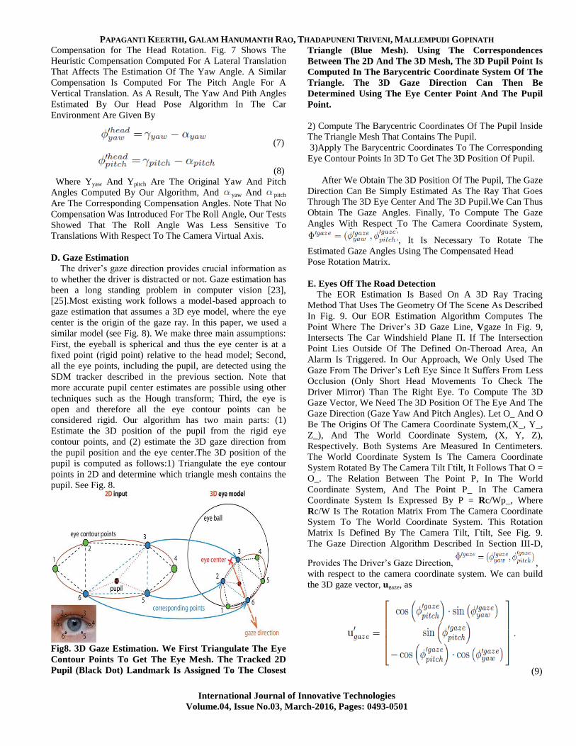
pupil. See Fig. 8.
Fig8. 3D Gaze Estimation. We First Triangulate The Eye
Contour Points To Get The Eye Mesh. The Tracked 2D
Pupil (Black Dot) Landmark Is Assigned To The Closest
Triangle (Blue Mesh). Using The Correspondences
Between The 2D And The 3D Mesh, The 3D Pupil Point Is
Computed In The Barycentric Coordinate System Of The
Triangle. The 3D Gaze Direction Can Then Be
Determined Using The Eye Center Point And The Pupil
Point.
2) Compute The Barycentric Coordinates Of The Pupil Inside
The Triangle Mesh That Contains The Pupil.
3)Apply The Barycentric Coordinates To The Corresponding
Eye Contour Points In 3D To Get The 3D Position Of Pupil.
After We Obtain The 3D Position Of The Pupil, The Gaze
Direction Can Be Simply Estimated As The Ray That Goes
Through The 3D Eye Center And The 3D Pupil.We Can Thus
Obtain The Gaze Angles. Finally, To Compute The Gaze
Angles With Respect To The Camera Coordinate System,
, It Is Necessary To Rotate The
Estimated Gaze Angles Using The Compensated Head
Pose Rotation Matrix.
E. Eyes Off The Road Detection
The EOR Estimation Is Based On A 3D Ray Tracing
Method That Uses The Geometry Of The Scene As Described
In Fig. 9. Our EOR Estimation Algorithm Computes The
Point Where The Driver’s 3D Gaze Line, Vgaze In Fig. 9,
Intersects The Car Windshield Plane Π. If The Intersection
Point Lies Outside Of The Defined On-Theroad Area, An
Alarm Is Triggered. In Our Approach, We Only Used The
Gaze From The Driver’s Left Eye Since It Suffers From Less
Occlusion (Only Short Head Movements To Check The
Driver Mirror) Than The Right Eye. To Compute The 3D
Gaze Vector, We Need The 3D Position Of The Eye And The
Gaze Direction (Gaze Yaw And Pitch Angles). Let O_ And O
Be The Origins Of The Camera Coordinate System,(X_, Y_,
Z_), And The World Coordinate System, (X, Y, Z),
Respectively. Both Systems Are Measured In Centimeters.
The World Coordinate System Is The Camera Coordinate
System Rotated By The Camera Tilt Γtilt, It Follows That O =
O_. The Relation Between The Point P, In The World
Coordinate System, And The Point P_ In The Camera
Coordinate System Is Expressed By P = Rc/Wp_, Where
Rc/W Is The Rotation Matrix From The Camera Coordinate
System To The World Coordinate System. This Rotation
Matrix Is Defined By The Camera Tilt, Γtilt, See Fig. 9.
The Gaze Direction Algorithm Described In Section III-D,
Provides The Driver’s Gaze Direction, ,
with respect to the camera coordinate system. We can build
the 3D gaze vector, ugaze, as
(9)
Design and Implementation of Driver Gaze Tracking System
International Journal of Innovative Technologies
Volume.04, Issue No.03, March-2016, Pages: 0493-0501
Using The 3D Head Coordinates, Q In Eq. (4), Our Head
Pose Algorithm Estimates The 3D Position Of The Driver’s
Head And Eyes With Respect To The Camera Coordinate
System, Vectors t’Head And t’Eye Respectively. Hence, The 3D
Gaze Line Can Be Expressed Using The Parametric 3D Line
Form As
(10)
Finally, The Intersection Point, Pinter, Is Given By The
Intersection Of The Gaze Vector, Vgaze, With The
Windshield Plane Π. The Equation Of The Windshield Plane
Π In The World Coordinate System Is Estimated Using Least
Squares Plane Fitting.
F. Sunglasses Detector
Our System Works Reliably With Drivers Of Different
Ethnicities Wearing Different Types Of Glasses. However, If
The Driver Is Wearing Sunglasses, It Is Not Possible To
Robustly Detect The Pupil. Thus, To Produce A Reliable
EOR Estimation In This Situation, The Vector Vgaze Will Be
Computed Using The Head Pose Angles. The Sunglasses
Detection Pipeline Is Shown In Fig. 10. First,Our System
Extracts SIFT Descriptors From The Area Of The Eyes And
Eyebrows, H1, . . . , Hn, And Concatenates Them To Build
The Feature Vector Ψ. Second, A Linear Support Vector
Machine (SVM) Classifier Is Used To Estimate If The Driver
Is Wearing Sunglasses. The SVM Classifier Has Been
Trained Using 7500 Images The Databases CMU Multi-PIE
Face Database [20] And The Pubfig Database [28]. The
Classifier Obtained 98% Accuracy In The Test Set, Which
Was Composed Of 600 Images Evenly Distributed Between
Positive And Negative Classes.
Fig. 10. Sunglasses classifier pipeline.
IV. RESULTS
This section evaluates the accuracy of our system in
different tasks. First, we compare our head pose estimation to
other state-of-the-art approaches. Second, we report the
performance of our EOR detection system in videos recorded
in the car environment. Finally, we evaluate the robustness of
the head pose estimation algorithm to extreme facial
deformations.
A. Head Pose Estimation
To Evaluate Our 3D-Based Head Pose Estimation
Algorithm, We Used The Boston University (BU) Dataset
Provided By La Cascia Et Al. [11]. This Dataset Contains 45
Video Sequences From 5 Different People With 200 Frames
In Each Video. As Described In The Previous Sections, Facial
Feature Detection Is Performed In Each Input Frame. Using
The 2D Tracked Landmarks,We Estimated The 3D Head
Orientation And Translation. The Distance Units Were Pre-
Normalized To Ensure That Translation Metrics Were In The
Same Scale. We Compared Our Head Pose Estimation
System With Deformable 3D Head Model (3D-Deform)
Against Four Other Methods In The Literature. Table I Shows
The Mean Absolute Error (MAE) Of The Head Pose Angles
For Different Algorithms.La Cascia Et Al. [11] Reported A
Method That Used A Manually Initialized Cylindrical Model
And Recursive Least Squares Optimization. Sung Et Al. [40]
Proposed A Method That Was Based On Active Appearance
Model [12] And Cylinder Head Models. Valenti Et Al. [42]
Used A Cylindrical Model And A Template Update Scheme
To Estimate Model Parameters On-The-Fly. As Table I
Shows, Our Method Based On A Deformable 3D Face Model
Is More Accurate Than These Three Methods. Finally,
Saragih Et Al. [38] Proposed An Algorithm Based On A 3D
Version Constrained Local Model (CLM) Which Estimates
The Pose Parameters By Maximizing The Local Patch
Response Using Linear Svms With Logistic Regressors. This
Method Obtained Better MAE Than Our Method, However
This Algorithm Requires A Recalibration Procedure Using
The Ground Truth When A Large Drift Occurs, Which Is
Infeasible In The Real Car Environment.
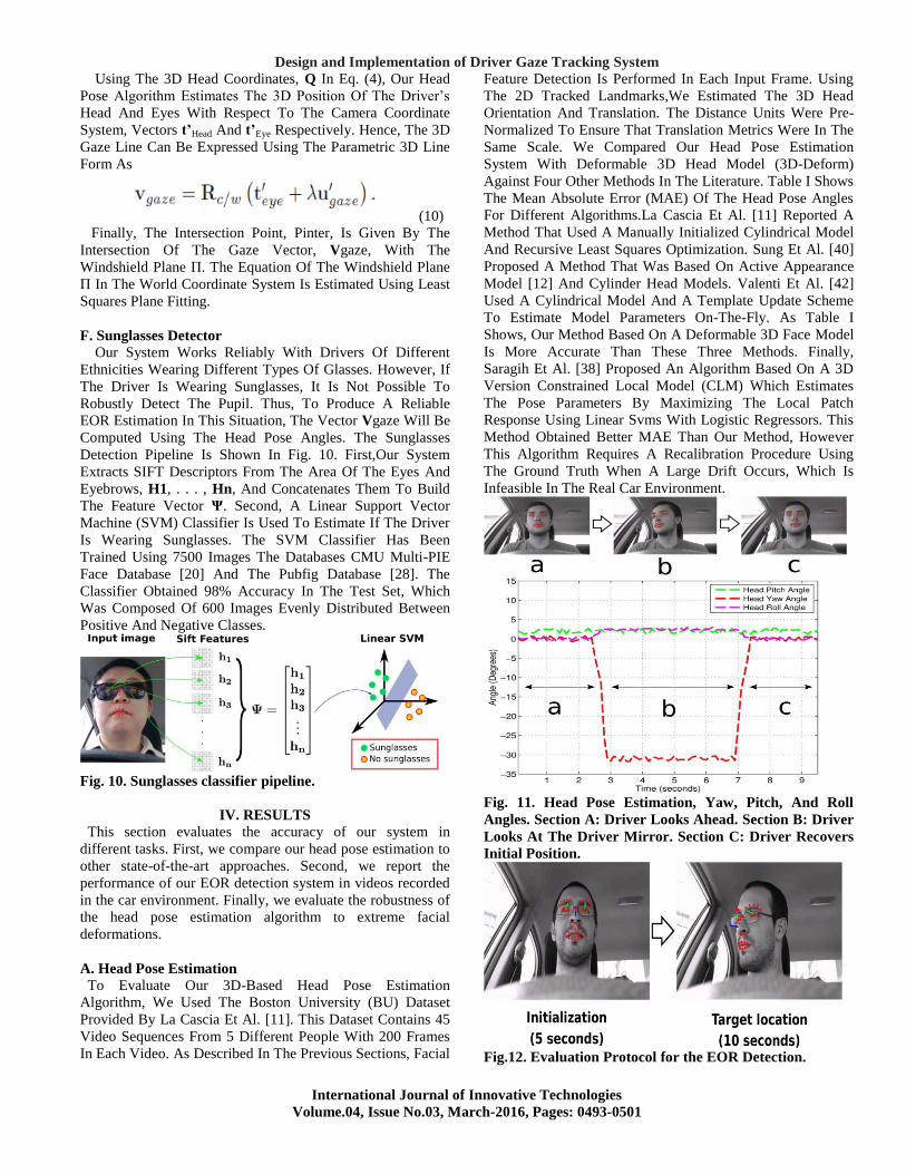
Fig. 11. Head Pose Estimation, Yaw, Pitch, And Roll
Angles. Section A: Driver Looks Ahead. Section B: Driver
Looks At The Driver Mirror. Section C: Driver Recovers
Initial Position.
Fig.12. Evaluation Protocol for the EOR Detection.
PAPAGANTI KEERTHI, GALAM HANUMANTH RAO, THADAPUNENI TRIVENI, MALLEMPUDI GOPINATH
International Journal of Innovative Technologies
Volume.04, Issue No.03, March-2016, Pages: 0493-0501
V. CONCLUSION
This Paper Describes A Real-Time EOR System Using
The Video From A Monocular Camera Installed On Steering
Wheel Column. Three Are The Main Novelties Of The
Proposed System: (1) Robust Face Landmark Tracker Based
On The Supervised Descent Method, (2) Accurate Estimation
Of 3D Driver Pose, Position, And Gaze Direction Robust To
Non-Rigid Facial Deformations, (3) 3D Analysis Of
Car/Driver Geometry For EOR Prediction. The Proposed
System Is Able To Detect EOR At Day And Night, And
Under A Wide Range Of Driver’s Characteristics (E.G.,
Glasses/Sunglasses/No Glasses, Ethnicities, Ages, . . .). The
System Does Not Require Specific Calibration Or Manual
Initialization. More Importantly, No Major Re-Calibration Is
Necessary If The Camera Position Is Changed Or If We Re-
Define A New Onthe-Road Area. This Is Due To The Explicit
Use Of 3D Geometric Reasoning. Hence, The Installation Of
The System In Different Car Models Does Not Require Any
Additional Theoretical Development. The System Achieved
An Accuracy Above 90 % For All Of The Scenarios
Evaluated, Including Night Time Operation. In Addition, The
False Alarm Rate In The On-The-Road Area Is Below 5 %.
Our Experiments Showed That Our Head Pose Estimation
Algorithm Is Robust To Extreme Facial Deformations. While
Our System Provided Encouraging Results, We Expect That
Improving The Facial Feature Detection In Challenging
Situations (E.G., Profile Faces, Faces With Glasses With
Thick Frames) Will Boost The Performance Of Our System.
Currently,We Are Also Working On Improving The Pupil
Detection Using Hough Transform-Based Techniques To
Further Improve The Gaze Estimation.
VI. REFERENCES
[1][Online].Available:Http://Www.Distraction.Gov/Content/
Get-Thefacts/Facts-And-Statistics.Html
[2] [Online]. Available: Http://Www.Seeingmachines.Com
[3] [Online]. Available: Http://Www.Smarteye.Se
[4] [Online]. Available: Http://Www.Smivision.Com
[5] C. Ahlstrom, K. Kircher, And A. Kircher, ―A Gaze-Based
Driver Distraction Warning System And Its Effect On Visual
Behavior,‖ IEEE Trans. Intell. Transp. Syst., Vol. 14, No. 2,
Pp. 965–973, Jun. 2013.
[6] A. Nabo, ―Driver Attention—Dealing With Drowsiness
And Distraction,‖Smart Eye, Gothenburg, Sweden, Tech.
Rep., 2009.
[7] J. P. Batista, ―A Real-Time Driver Visual Attention
Monitoring System,‖ In Pattern Recognition And Image
Analysis, Vol. 3522, Berlin, Germany:Springer-Verlag, 2005,
Pp. 200–208.
[8] L. M. Bergasa, J. Nuevo, M. A. Sotelo, R. Barea, And M.
E. Lopez, ―Realtime System For Monitoring Driver
Vigilance,‖ IEEE Trans. Intell. Transp.Syst., Vol. 7, No. 1,
Pp. 63–77, Mar. 2006.
[9] V. Blanz And T. Vetter, ―A Morphable Model For The
Synthesis Of 3D Faces,‖ In Proc. 26th Annu. Conf. Comput.
Graph. Interact. Tech., 1999,Pp. 187–194.
[10] C. Cao, Y. Weng, S. Zhou, Y. Tong, And K. Zhou,
―Facewarehouse: A 3D Facial Expression Database For
Visual Computing,‖IEEE Trans. Vis. Comput. Graphics, Vol.
20, No. 3, Pp. 413–425,Mar. 2014.
[11] M. L. Cascia, S. Sclaroff, And V. Athitsos, ―Fast,
Reliable Head Tracking Under Varying Illumination: An
Approach Based On Registration Of Texturemapped 3D
Models,‖ IEEE Trans. Pattern Anal. Mach. Intell., Vol. 22,
No. 6, Pp. 322–336, Apr. 2000.
[12] T. Cootes, G. Edwards, And C. Taylor, ―Active
Appearance Models,‖IEEE Trans. Pattern Anal. Mach. Intell.,
Vol. 23, No. 6, Pp. 681–685,Jun. 2001.
[13] F. De La Torre And M. H. Nguyen, ―Parameterized
Kernel Principal Component Analysis: Theory And
Applications To Supervised And Unsupervised Image
Alignment,‖ In Proc. IEEE Conf. Comput. Vis. Pattern
Recog., 2008,Pp. 1–8.
[14] Y. Dong, Z. Hu, K. Uchimura, And N. Murayama,
―Driver Inattention Monitoring System For Intelligent
Vehicles: A Review,‖ IEEE Trans. Intell. Transp. Syst., Vol.
12, No. 2, Pp. 596–614, Jun. 2011.
[15] N. Edenborough Et Al., ―Driver State Monitor From
DELPHI,‖ In Proc. IEEE Conf. Comput. Vis. Pattern Recog.,
2005, Pp. 1206–1207.
[16] G. M. Fitch Et Al., ―The Impact Of Hand-Held And
Hands-Free Cell Phone Use On Driving Performance And
Safety-Critical Event Risk,‖ Nat. Highway Traffic Safety
Admin., Washington, DC, USA, Tech. Rep. DOT HS 811
757, 2013.
[17] L. Fletcher, N. Apostoloff, L. Petersson, And A.
Zelinsky, ―Vision In And Out Of Vehicles,‖ IEEE Intell.
Syst., Vol. 18, No. 3, Pp. 12–17,May/Jun. 2003.
[18] L. Fletcher, G. Loy, N. Barnes, And A. Zelinsky,
―Correlating Driver Gaze With The Road Scene For Driver
Assistance Systems,‖ Robot. Auton. Syst.,Vol. 52, No. 1, Pp.
71–84, Jul. 2005.
[19] L. Fletcher And A. Zelinsky, ―Driver Inattention
Detection Based On Eye Gaze—Road Event Correlation,‖ Int.
J. Robot. Res., Vol. 28, No. 6,Pp. 774–801, Jun. 2009.
[20] R. Gross, I. Matthews, J. Cohn, T. Kanade, And S.
Baker, ―Multi-Pie,‖Image Vis. Comput., Vol. 28, No. 5, Pp.
807–813, 2010.
[21] D. W. Hansen And Q. Ji, ―In The Eye Of The Beholder:
A Survey Of Models For Eyes And Gaze,‖ IEEE Trans.
Pattern Anal. Mach. Intell., Vol. 32,No. 3, Pp. 478–500, Mar.
2010.
[22] J. L. Harbluk, Y. I. Noy, P. L. Trbovich, And M.
Eizenman, ―An On-Road Assessment Of Cognitive
Distraction: Impacts On Drivers’ Visual Behavior And
Braking Performance,‖ Accid. Anal. Prev., Vol. 39, No. 2, Pp.
372–379,Mar. 2007.
[23] J. Heinzmann And A. Zelinsky, ―3D Facial Pose And
Gaze Point Estimation Using A Robust Real-Time Tracking
Paradigm,‖ In Proc. 3rd IEEE Int. Conf.Autom. Face Gesture
Recog., 1998, Pp. 142–147.
[24] H. Ishiguro Et Al., ―Development Of Facial-Direction
Detection Sensor,‖ In Proc. 13th ITS World Congr., 2006, Pp.
1–8.
[25] T. Ishikawa, S. Baker, I. Matthews, And T. Kanade,
―Passive Driver Gaze Tracking With Active Appearance
Design and Implementation of Driver Gaze Tracking System
International Journal of Innovative Technologies
Volume.04, Issue No.03, March-2016, Pages: 0493-0501
Models,‖ In Proc. 11th World Congr.Intell. Transp. Syst.,
2004, Pp. 1–12.
[26] Q. Ji And X. Yang, ―Real Time Visual Cues Extraction
For Monitoring Driver Vigilance,‖ In Computer Vision
Systems, Berlin, Germany: Springer-Verlag, 2001, Pp. 107–
124.
[27] Q. Ji And X. Yang, ―Real-Time Eye, Gaze, And Face
Pose Tracking For Monitoring Driver Vigilance,‖ Real-Time
Imag., Vol. 8, No. 5, Pp. 357–377,Oct. 2002.
[28] N. Kumar, A. C. Berg, P. N. Belhumeur, And S. K.
Nayar, ―Attribute And Simile Classifiers For Face
Verification,‖ In Proc. IEEE ICCV, Oct. 2009,Pp. 365–372.
[29] J. Lee Et Al., ―Detection Of Driver Distraction Using
Vision-Based Algorithms,‖ In Proc. 23rd Enhanced Safety
Veh. Conf., Seoul, Korea, 2013,11-0322.
[30] S. J. Lee, J. Jo, H. G. Jung, K. R. Park, And J. Kim,
―Real-Time Gaze Estimator Based On Driver’s Head
Orientation For Forward Collision Warning System,‖ IEEE
Trans. Intell. Transp. Syst., Vol. 12, No. 1, Pp. 254–267,Mar.
2011.
[31] D. Lowe, ―Distinctive Image Features From Scale-
Invariant Keypoints,‖ Int. J. Comput. Vis., Vol. 60, No. 2, Pp.
91–110, Nov. 2004.
[32] C. Morimoto, D. Koons, A. Amir, And M. Flickner,
―Pupil Detection And Tracking Using Multiple Light
Sources,‖ Image Vis. Comput., Vol. 18, No. 4,Pp. 331–335,
Mar. 2000.
[33] E. Murphy-Chutorian, A. Doshi, And M. M. Trivedi,
―Head Pose Estimation For Driver Assistance Systems: A
Robust Algorithm And Experimental Evaluation,‖ In Proc.
IEEE Intell. Transp. Syst. Conf., 2007,Pp. 709–714.
[34] E. Murphy-Chutorian And M. M. Trivedi, ―Head Pose
Estimation In Computer Vision: A Survey,‖ IEEE Trans.
Pattern Anal. Mach. Intell., Vol. 31,No. 4, Pp. 607–626, Apr.
2009.
[35] E. Murphy-Chutorian And M. M. Trivedi, ―Head Pose
Estimation And Augmented Reality Tracking: An Integrated
System And Evaluation For Monitoring Driver Awareness,‖
IEEE Trans. Intell. Transp. Syst., Vol. 11, No. 2,Pp. 300–311,
Jun. 2010.
[36] E. M. Rantanen And J. H. Goldberg, ―The Effect Of
Mental Workload On The Visual Field Size And Shape,‖
Ergonomics, Vol. 42, No. 6, Pp. 816–834,Jun. 1999.
[37] M. Rezaei And R. Kletter, ―Look At The Driver, Look
At The Road: No Distraction! No Accident!‖ In Proc. IEEE
CVPR, 2014, Pp. 129–136. [38] J. M. Saragih, S. Lucey, And
J. F. Cohn, ―Deformable Model Fitting By Regularized
Landmark Mean-Shift,‖ Int. J. Comput. Vis., Vol. 91, No. 2,
Pp. 200–215, Jan. 2011.
[39] P. Smith, M. Shah, And N. Da Vitoria Lobo,
―Determining Driver Visual Attention With One Camera,‖
IEEE Trans. Intell. Transp. Syst., Vol. 4,No. 4, Pp. 205–218,
Dec. 2003.
[40] J. Sung, T. Kanade, And D. Kim, ―Pose Robust Face
Tracking By Combining Active Appearance Models And
Cylinder Head Models,‖ Int. J. Comput. Vis.,Vol. 80, No. 2,
Pp. 260–274, Nov. 2008.
[41] J. Tison, N. Chaudhary, And L. Cosgrove, ―National
Phone Survey On Distracted Driving Attitudes And
Behaviors,‖ Nat. Highway Traffic Safety Admin.,
Washington, DC, USA, Tech. Rep., 2011.
[42] R. Valenti, Z. Yucel, And T. Gevers, ―Robustifying Eye
Center Localization By Head Pose Cues,‖ In Proc. IEEE
Conf. Comput. Vis. Pattern Recog.,2009, Pp. 612–618.
[43] D. Vlasic, M. Brand, H. Pfister, And J. Popovi´C, ―Face
Transfer With Multilinear Models,‖ ACM Trans. Graph., Vol.
24, No. 3, Pp. 426–433,Jul. 2005.
[44] X. Xiong And F. De La Torre, ―Supervised Descent
Method And Its Applications To Face Alignment,‖ In Proc.
IEEE Conf. Comput. Vis. Pattern Recog.,2013, Pp. 532–539.
[45] F. Yang, E. Shechtman, J.Wang, L. Bourdev, And D.
Metaxas, ―Face Morphing Using 3D-Aware Appearance
Optimization,‖ In Proc. Graph. Interace Conf. Can. Inf.
Process. Soc., 2012, Pp. 93–99.