design and implementation of multi-sensor based ...abbreza.com/pdf/minesweeping_robot.pdfdesign and...
TRANSCRIPT

Design and Implementation of Multi-sensor BasedAutonomous Minesweeping Robot
Reza AbbaspourDepartment of Computer Science
University of VaasaVaasa, Finland
Abstract— The scope of this paper is to introduce the architectureof a minesweeping robot which is designed and implemented as aresearch project. Reduction of the human activities in dangerousenvironment is the first objective of employing the autonomousmobile robots in many applications. Mine detection is a riskyaction that can be done by either human or robot. Aria Robot isan autonomous four wheels robot that is designed to searchthrough an arbitrary minefield for detecting landmines. Wirelessconnection is established between the local controller on the robotand general controller that is installed at the outside of theminefield to handle the whole navigation procedure. A personalcomputer (PC) acts as the general controller which is responsiblefor mapping the landmines and determining some generalsettings for local controller. The local controller navigates therobot based on the feedbacks from several sensors to detect thebarriers and landmines such as digital compass, optical shaftencoder, current sensor, ultrasonic range finder sensors, infrared(IR) sensor and mine detector sensor.
Keywords-Minesweeping; Autonamous Mobile robot; Minedetector sensor; DC motor driver; Zigbee transceiver;
I. INTRODUCTION
The act of removing landmines from the minefield is calledmine clearance or demining process. On the other hand minedetection is referred to minesweeping procedure. Mineclearance term is often used for removing landmines withinactive combat zones. In military applications the priority ofspeed is rather than exactitude. In contrast with humanitarianpurposes, exactitude of minesweeping procedure becomesmore important. Minesweepers use many tools in order toaccomplish their task. Trained animals such as dogs and ratsare historically employed to find the landmines. The moderntechniques of landmine detection are relied on metal detectorsor vehicles with special mechanical devices that are designedfor this application. To reduce the human activity within theminefield, all these tools and techniques are applied. Recentlyautonomous robots are being developed to decrease thepossible civilian mine casualties. Minesweeping robots areclassified into the rescue robots category that is recently a hottopic in robotic science. Fig. 1 shows the first generation ofAria Robot which is designed and implemented to findlandmines automatically. The performance of the robot wasdemonstrated in deminer robot league of annual robotic
competition of Babol University of Technology (Iran) in 2008and achieved first award of best technical design.
Design of a full autonomous minesweeping robot to reducethe risk of demining in minefield was the first objective of thisproject. Implementation phase was included mechanicalplatform design, electrical units and embedded programmingstage, which the design steps are followed according to thediagram in Fig. 2.
The area where the robot must seek for landmines,determines the mechanical platform characteristics. Based onthe robot mechanical features, control scenario was revised toenhance the possible performance degradations at seconddesign phase. The first generation of Aria Robot exploitsnavigation scenario based on image processing technique. Apersonal computer (PC) has been employed as the maincontroller where was put outside of minefield and wasconnected to the robot by a wireless link. All the commandsand data were transferred through a 2.4 GHz ZigBee wirelesstransceiver (XBEE) to the robot from main controller and viceversa. Localization and tracking of Aria Robot was captured bya normal camera (25 frames per second) that was fixed at the
978-1-4244-7286-4/10/$26.00 ©2010 IEEE
Figure 2. The design and implementation steps.
Figure 1. First generation of Aria Robot.
2010 International Congress on Ultra Modern Telecommunications and Control Systems and Workshops (ICUMT)
443
ceiling of the laboratory where the arbitrary minefield waslocated. The mentioned scenario was ideal for indoornavigation and mapping the detected landmines, but has severaldisadvantages for minesweeping in real conditions. The secondgeneration of Aria Robot was designed to operate more flexiblein real condition based on the feedbacks from the local sensors.Consequently the local controller on the second generation ismore important and the diversity of sensors for local navigationis rather than the first generation. In the second generation ofAria Robot, the PC responsibility is changed from maincontroller to general controller. This means that the navigationprocedure is handled by the robot and the process of mappingthe detected landmines is preformed at PC side. Additionallysome general settings are determinable in PC side such as pathfinding strategy and the maximum allowed velocity of therobot. Contrastingly the local controller handles all thefunctions of navigation and localization procedures based onthe feedbacks from mine detector sensor, digital compass,optical shaft encoder, current sensor, ultrasonic range findersensors and infrared (IR) sensor to detect the barriers andlandmines.
II. MECHANICAL PLATFORM
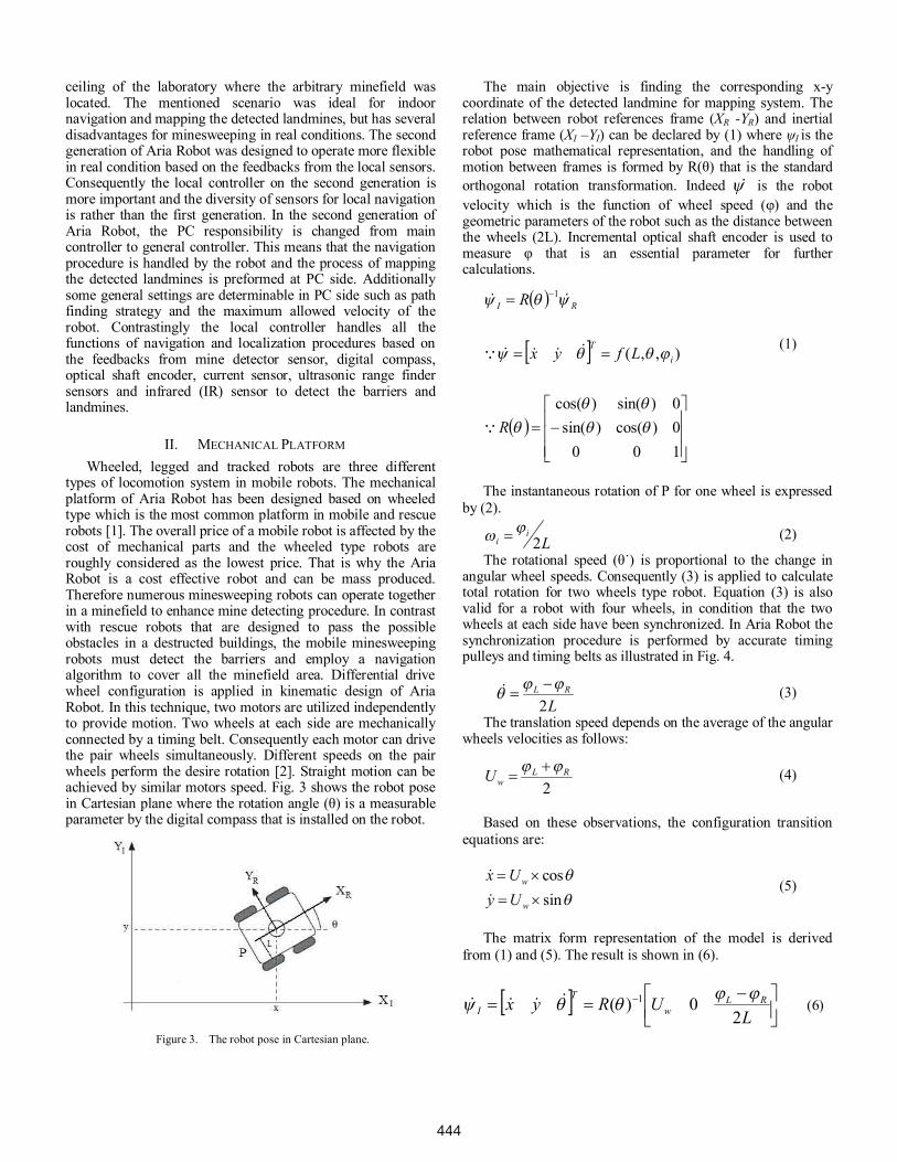
Wheeled, legged and tracked robots are three differenttypes of locomotion system in mobile robots. The mechanicalplatform of Aria Robot has been designed based on wheeledtype which is the most common platform in mobile and rescuerobots [1]. The overall price of a mobile robot is affected by thecost of mechanical parts and the wheeled type robots areroughly considered as the lowest price. That is why the AriaRobot is a cost effective robot and can be mass produced.Therefore numerous minesweeping robots can operate togetherin a minefield to enhance mine detecting procedure. In contrastwith rescue robots that are designed to pass the possibleobstacles in a destructed buildings, the mobile minesweepingrobots must detect the barriers and employ a navigationalgorithm to cover all the minefield area. Differential drivewheel configuration is applied in kinematic design of AriaRobot. In this technique, two motors are utilized independentlyto provide motion. Two wheels at each side are mechanicallyconnected by a timing belt. Consequently each motor can drivethe pair wheels simultaneously. Different speeds on the pairwheels perform the desire rotation [2]. Straight motion can beachieved by similar motors speed. Fig. 3 shows the robot posein Cartesian plane where the rotation angle ( ) is a measurableparameter by the digital compass that is installed on the robot.
The main objective is finding the corresponding x-ycoordinate of the detected landmine for mapping system. Therelation between robot references frame (XR -YR) and inertialreference frame (XI –YI) can be declared by (1) where I is therobot pose mathematical representation, and the handling ofmotion between frames is formed by R( ) that is the standardorthogonal rotation transformation. Indeed is the robotvelocity which is the function of wheel speed ( ) and thegeometric parameters of the robot such as the distance betweenthe wheels (2L). Incremental optical shaft encoder is used tomeasure that is an essential parameter for furthercalculations.
1000)cos()sin(0)sin()cos(
),,(
1
R
Lfyx
R
iT
RI
(1)
The instantaneous rotation of P for one wheel is expressedby (2).
Li
i 2 (2)
The rotational speed ( ) is proportional to the change inangular wheel speeds. Consequently (3) is applied to calculatetotal rotation for two wheels type robot. Equation (3) is alsovalid for a robot with four wheels, in condition that the twowheels at each side have been synchronized. In Aria Robot thesynchronization procedure is performed by accurate timingpulleys and timing belts as illustrated in Fig. 4.
LRL
2(3)
The translation speed depends on the average of the angularwheels velocities as follows:
2RL
wU (4)
Based on these observations, the configuration transitionequations are:
sincos
w
w
UyUx
(5)
The matrix form representation of the model is derivedfrom (1) and (5). The result is shown in (6).
LURyx RL
wT
I 20)( 1 (6)
Figure 3. The robot pose in Cartesian plane.
444
Equation (6) helps to compute the robot positionproportionally based on the feedbacks from digital compassand optical shaft encoder. The Navigation algorithm andmapping system exploit the information that is provided by theabove calculations.
III. ELECTRICAL UNITS
The general controller mainly accomplishes the mappingprocedure. This means that the detected landmines byminesweeping robot must be visible on a virtual map fordemining process. The application which is created byLabview software can analyze the received data from the robotand generates a text file with spreadsheet format that containsthe relevant detected landmines coordinates. This file format iswidely supported by many applications and it can be openedand analyzed in many ways. Consequently the exact positionsof landmines can be represented on a virtual map that isperformed by Matlab from the generated file. In addition thebasic settings of the local controller such as the maximumallowed sweeping speed and selecting the predefinedsweeping scenario are configurable by the general control. Themanual control is also possible optionally by the generalcontroller whenever the operator decides to navigate the robotmanually. The general controller tasks are simply handled by alaptop which is connected to a XBEE through the universalserial bus (USB) port as illustrated in Fig. 5.
A. PC Side Hardware ConfigurationFT232 is a well-known USB to universal asynchronous
receiver-transmitter (UART) converter integrated circuit (IC)that is used to connect the XBEE module to PC USB port. Thehardware can support the data rate up to 250 kbps and exploits128-bits advanced encryption standard (AES) algorithm toguarantee the security of wireless communication. Multipleaccess capability of the implemented wireless link is a keyfeature that is taken into account for future developing. Asdescribed in previous section, Aria Robot is a cost effectivesystem so numerous low-cost robots can be manufactured tosweep a landmine under control of a single general controllerfor increasing the accuracy and time reduction of theminesweeping process.
B. Local Controller Hardware ConfigurationThe processing on local controller is distributed among the
main AVR microcontroller (ATMEGA16) and six auxiliarymicrocontrollers [3]. The main microcontroller is utilized withI2C bus, serial and parallel bus to communicate withsubsystems as illustrated in Fig. 6.
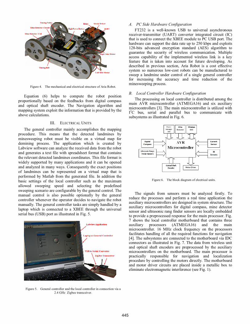
The signals from sensors must be analyzed firstly. Toreduce the processes and perform a real time application theauxiliary microcontrollers are designed in system structure. Theauxiliary microcontrollers for digital compass, mine detectorsensor and ultrasonic rang finder sensors are locally embeddedto provide a preprocessed response for the main processor. Fig.7 shows the local controller motherboard that contains threeauxiliary processors (ATMEGA16) and the mainmicrocontroller. 16 MHz clock frequency on the processorsfacilitates handling of all the required functions for navigation[4]. The subsystems are connected to the motherboard via IDCconnectors as illustrated in Fig. 7. The data from wireless unitand optical shaft encoders are preprocessed by the auxiliarymicrocontrollers on the motherboard. The main processor ispractically responsible for navigation and localizationprocedure by controlling the motors directly. The motherboardand motor driver circuits are placed inside a metallic box toeliminate electromagnetic interference (see Fig. 1).
Figure 6. The block diagram of electrical units.
Figure 5. General controller and the local controller in connection via a2.4 GHz Zigbee transceiver.
Figure 4. The mechanical and electrical structure of Aria Robot.
445
C. Power Management unitThe robot is powered by batteries. The electrical units such
as the controller and sensors are isolated electrically from theactuators for noise reduction. Therefore the actuators aresupplied by 18.5v, 5000 mAh Lit-Polymer battery (see Fig. 4)separately. The brushed DC motors generate high power noiseon power supply line that causes the performance degradationof mine detector sensor which is so sensitive to noise. That iswhy the battery for supplying the actuators is separated fromthe battery for supplying of the circuits. Local controller’scircuits are utilized with a DC to DC down-converter switchingregulator (LM2576) to filter any possible high frequency noiseon power supply line. The required low noise negative voltageis also provided by power management unit for mine detectorsensor. Damage occurs on Lit-Polymer battery whenever thebattery voltage, drops below the standard cut-off voltage.Consequently it is vital to monitor the level of voltagecontinuously through a simple voltage comparator circuit basedon LM311 and a voltage reference IC. In case of reaching thebattery voltage below the cut-off threshold the mainmicrocontroller stops the actuators.
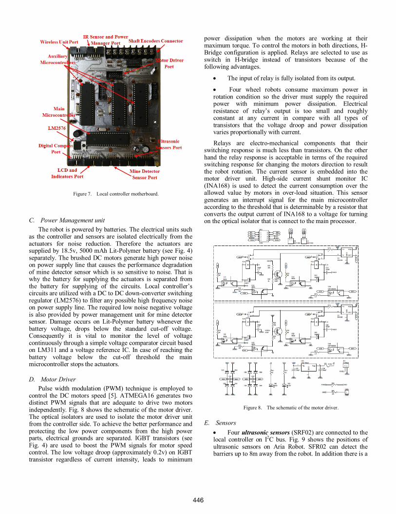
D. Motor DriverPulse width modulation (PWM) technique is employed to
control the DC motors speed [5]. ATMEGA16 generates twodistinct PWM signals that are adequate to drive two motorsindependently. Fig. 8 shows the schematic of the motor driver.The optical isolators are used to isolate the motor driver unitfrom the controller side. To achieve the better performance andprotecting the low power components from the high powerparts, electrical grounds are separated. IGBT transistors (seeFig. 4) are used to boost the PWM signals for motor speedcontrol. The low voltage droop (approximately 0.2v) on IGBTtransistor regardless of current intensity, leads to minimum
power dissipation when the motors are working at theirmaximum torque. To control the motors in both directions, H-Bridge configuration is applied. Relays are selected to use asswitch in H-bridge instead of transistors because of thefollowing advantages.
The input of relay is fully isolated from its output.
Four wheel robots consume maximum power inrotation condition so the driver must supply the requiredpower with minimum power dissipation. Electricalresistance of relay’s output is too small and roughlyconstant at any current in compare with all types oftransistors that the voltage droop and power dissipationvaries proportionally with current.
Relays are electro-mechanical components that theirswitching response is much less than transistors. On the otherhand the relay response is acceptable in terms of the requiredswitching response for changing the motors direction to resultthe robot rotation. The current sensor is embedded into themotor driver unit. High-side current shunt monitor IC(INA168) is used to detect the current consumption over theallowed value by motors in over-load situation. This sensorgenerates an interrupt signal for the main microcontrolleraccording to the threshold that is determinable by a resistor thatconverts the output current of INA168 to a voltage for turningon the optical isolator that is connect to the main processor.
E. SensorsFour ultrasonic sensors (SRF02) are connected to the
local controller on I2C bus. Fig. 9 shows the positions ofultrasonic sensors on Aria Robot. SFR02 can detect thebarriers up to 8m away from the robot. In addition there is a
Figure 8. The schematic of the motor driver.
Figure 7. Local controller motherboard.
446

capability to measure the distance between the robot andthe barriers.
Aria Robot is utilized with a digital compass(CMPS03) which can measure the rotation angle of therobot by computing the direction of the horizontalcomponent of the Earths magnetic field. CMPS03 is sosensitive to undesirable electromagnetic waves which areemitted from metal detector sensor and actuators. Inconsequence it is installed far away from them to keep itsaccuracy (see Fig. 9). CMPS03 is jointed with an auxiliarymicrocontroller (ATMEGA16) which is used for calibrationand monitoring of the compass output. Digital compass unitis connected to the main microcontroller on the same I2Cbus that the ultrasonic sensors are connected.
An IR sensor (GP2D12) is used to detect theobstacles which are not detectable by the ultrasonic sensors.The IR sensor is placed at the front of the robot (see Fig. 9)with maximum range 80 cm. The IR beam is modulated toprevent any possible interference with natural light.Measuring the level of the analog signal at the output of IRsensor by analog to digital converter (ADC) on the mainprocessor can estimate the distance between the robot andthe detected barriers.
Incremental optical shaft encoders are included onthe gear motors that generate 1000 pulses per round. Theyare used to count the robot wheels turns. To prevent anyerror and failure on computing the speed of wheels anauxiliary AVR microcontroller (ATMEGA16) isparticularly designed on the motherboard to capture thepulses from shaft encoders. Consequently the basiccomputations which are discussed in section II are handledby this processor in order to take the load off of the mainprocessor. This unit is connected to the mainmicrocontroller via 8-bit parallel bus to increase reliability.
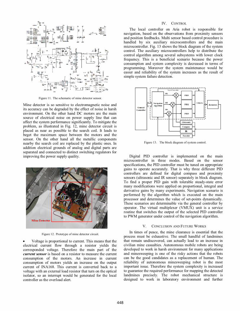
In fact the mine detector is the most critical part inAria Robot. The sensor detects the metal that is used insidea landmine and simply, it can be considered as a metaldetector. The type of metal detector on Aria Robot is pulseinduction (PI) that exploits mono coil configuration.Consequently a single search coil is fitted at the front of therobot (see Fig. 1). A simplified diagram of the metaldetector circuit is illustrated in Fig. 10.
The main part of a PI detector is a MOSFET transistor asthe coil switch, with a high current capacity and a highbreakdown voltage. The MOSFET, shorts the coil across thebattery voltage, which yields a large coil current; and turns thecoil current off as quickly as possible. A parallel resistor withcoil absorbs the energy that was stored in the coil to turn thecoil current off rapidly and it leads to energy dissipation asheat. Therefore the circuit is equipped with a heat-sink and ahigh speed fan. That is why PI detectors require high powersupplying. Current flowing through the coil yields a magneticfield around the coil and whenever the coil is switched off, thecurrent ceases, and so does the magnetic field. The collapse ofthe magnetic field cause to induce eddy currents in the nearbymetal target that leads to generate a counter-magnetic field [6].The affect of counter-magnetic field on the search coil wouldbe appeared as a distortion on the signal from the coil thatindicates a piece of metal is hunted. In this design to derive theinformation from the distorted signal, high slew rate amplifier(LM318) is employed to boost the signal as a pre-amplifier.Sample and hold circuit partitions the desire part of signalwhich is distorted by the effect of counter-magnetic field then acurrent buffer isolates the ADC circuit electrically from thesignal conditioning unit. The ADC circuit is integrated into themicrocontroller (ATMEGA8) which is designed on the metaldetector sensor and digitizes the analog signals from theprevious stage. ATMEGA8 can analyze some characteristics ofthe signal that leads to estimate some features of the detectedmetal such as its size and depth. Additionally the requiredclock pulse for MOSFET switching and sampling circuit isgenerated by ATMEGA8. The schematic of PI detector isshown in Fig. 11. The sensor is implemented on Aria Robotand tested successfully. Maximum detection depth range isdependent upon coil radius. Consequently the typical detectionrange by the coil on the robot is 40 cm.
Figure 10. The block diagram of mine detector.
Figure 9. Position of the sensors on second generation of Aria Robot.
447
Mine detector is so sensitive to electromagnetic noise andits accuracy can be degraded by the effect of noise in harshenvironment. On the other hand DC motors are the mainsource of electrical noise on power supply line that canaffect the system performance significantly. To mitigate theproblem, as illustrated in Fig. 12, mine detector circuit isplaced as near as possible to the search coil. It leads tobeget the maximum space between the motors and thesensor. On the other hand all the metallic componentsnearby the search coil are replaced by the plastic ones. Inaddition electrical grounds of analog and digital parts areseparated and connected to distinct switching regulators forimproving the power supply quality.
Voltage is proportional to current. This means that theelectrical current flow through a resistor yields thecorresponded voltage. Therefore the main part of thecurrent sensor is based on a resistor to measure the currentconsumption of the motors. An increase in currentconsumption of motors yields an increase on the outputcurrent of INA168. This current is converted back to avoltage with an external load resistor that turn on the opticalisolator, so an interrupt would be generated for the localcontroller as the overload alert.
IV. CONTROL
The local controller on Aria robot is responsible fornavigation, based on the observations from proximity sensorsand position feedbacks. Multi sensor based control procedure ishandled by six auxiliary microcontrollers and the mainmicrocontroller. Fig. 13 shows the block diagram of the systemcontrol. The auxiliary microcontrollers help to distribute thecontrol algorithm among several subsystems with lower clockfrequency. This is a beneficial scenario because the powerconsumption and system complexity is decreased in terms ofprogramming. Moreover the system maintenance would beeasier and reliability of the system increases as the result ofsimple system failure detection.
Digital PID controller is implemented on the mainmicrocontroller in three modes. Based on the sensorspecifications, the PID controller must be tuned on appropriategains to operate accurately. That is why three different PIDcontrollers are defined for digital compass and proximitysensors (ultrasonic and IR sensor) separately in block diagram.To find a proper PID gain with tolerable steady-state errormany modifications were applied on proportional, integral andderivative gains by many experiments. Navigation scenario isperformed by the algorithm which is executed on the mainprocessor and determines the value of set-points dynamically.These scenarios are determinable via the general controller byoperator. The virtual multiplexer (VMUX) unit is a serviceroutine that switches the output of the selected PID controllerto PWM generator under control of the navigation algorithm.
V. CONCLUSION AND FUTURE WORKS
In times of peace, the mine clearance is essential that theprocess must be exhaustive. The small handful of landminesthat remain undiscovered, can actually lead to an increase incivilian mine casualties. Autonomous mobile robots are beingdeveloped to work in harsh environment for many applicationsand minesweeping is one of the risky actions that the robotscan be the good candidates as a replacement of human. Thereliability of autonomous minesweeping robot is the mostimportant issue. Therefore the system complexity is increasedto guarantee the required performance for mapping the detectedlandmines precisely. The robot mechanical structure isdesigned to work in laboratory environment and further
Figure 13. The block diagram of system control.
Figure 12. Prototype of mine detector circuit.
Figure 11. The schematic of mine detector sensor.
448

developing can be done on a platform that is suited for realconditions. Mobile robot navigation is also an open researchissue that can be applied on minesweeper robots to enhance theminesweeping algorithm. Anti-personnel mines could not betriggered by Aria Robot’s weight (4 Kg) because they aretypically designed to be triggered by any movement or pressuregreater than 5 Kg. Consequently the numerous light-weight,cost effective robots can be employed to cover a minefieldquickly and it can be the future research on minesweeperrobots.
ACKNOWLEDGMENT
The financial support for this project from Pars Robot AriaCompany is gratefully acknowledged.
REFERENCES
[1] J. Borenstein, “Control and kinematic design of multi-degree-of freedommobile robots with compliant linkage,” in IEEE Trans. Robot.Autonomous, vol. 11, pp. 21-35, 1995.
[2] Y. Chung, C. Park, F. Harashima, “A position control differential drivewheeled mobile robot,” in IEEE Trans. Ind. Electron., Vol.48, pp.853-863, 2001.
[3] P. Arató, S. Juhász, Z. A. Mann, A. Orbán, D. Papp, “Hardware/softwarepartitioning in embedded system design,” in Proc. IEEE Int. Symposiumon Intelligent Signal Process., pp. 197- 202, 2003.
[4] I. Panagopoulos, C. Pavlatos, G. Papakonstantinou, “An EmbeddedMicroprocessor for Intelligent Control,” in J. Intell. Robot. Syst.,Springer Netherlands, vol. 42, pp. 179-211, 2005.
[5] Richard Valentine, Motor Control Electronics Handbook, McGraw-HillHandbook, Chapter 3, 1998.
[6] R. Medek, J. Nicolics, D. Schrottmayer, “High Sensitive Pulse InductiveEddy Current Measurement For Mine Detection Systems,’’ in Proc. 24thInt. Spring Seminar on Electron. Technol., Calimanesti-Caciulata, pp.207-211, 2001.
[7] C. F. Olson, “Probabilistic self-localization for mobile robots,” in IEEETrans. Robot. Autom., vol. 16, no. 1, pp. 55-66, 2000.
[8] A. Stroupe, K. Sikorski, T. Balch, “Constraint-based landmarklocalization,” in Proc. RoboCup 2002: Robot Soccer World Cup IV,Fukuoka, Japan, Springer-Verlag, 2002.
[9] H. Chitsaz, S. M. LaValle, D. J. Balkcom, M. T. Mason, “MinimumWheel-Rotation Paths for Differential-Drive Mobile Robots,” in IEEEInt. Conf. Robot. Autom., ICRA’06, pp. 1616-1623, 2006.
[10] R. A. Brooks, ‘‘A robust layered control system for a mobile robot,’’ inIEEE J. Robot. Autom., vol. 2, no. 1, pp. 14–23, 1986.
[11] D. Pagac, E. M. Nebot, H. Durrant-Whyte, ‘‘An evidential approach tomap-building for autonomous vehicles,’’ in IEEE Trans. Robot.Automat., vol. 14, no. 4, pp. 623–629, 1998.
[12] N. M. Sgouros, ‘‘Qualitative navigation for autonomous wheelchairrobots in indoor environments,’’ in J. Autonomous Robots, vol. 12, no.3, pp. 257–266, 2002.
[13] D. Fox, W. Burgard, F. Dellaert, S. Thrun, “Monte Carlo Localization:Efficient Position Estimation for Mobile Robots,” in Proc. 16th NationalConf. on Artificial Intell. (AAAI ’99), 1999.
[14] I.E. Paromatchik, U. Rembold, “A practical approach to motiongeneration and control of omni directional mobile robot,” in Proc. IEEEInt. Conf. on Robot. Autom., pp. 2790-2795, 1994.
449