design and manufacturing of soft robotics mechanisms
TRANSCRIPT

Samuel José dos Reis Alves
DESIGN AND MANUFACTURING OF SOFT
ROBOTICS MECHANISMS: IMPROVING THE
RELIABILITY OF PNEUMATIC-BASED
SOLUTIONS
Dissertação no âmbito do Mestrado Integrado em Engenharia Mecânica, no ramo
de produção e projeto orientada pelo Professor Doutor Pedro Mariano Simões
Neto e apresentada ao Departamento de Engenharia Mecânica da Universidade de
Coimbra.
Outubro de 2020


Design and manufacturing of soft robotics
mechanisms: improving the reliability of
pneumatic-based solutions
Submitted in Partial Fulfilment of the Requirements for the Degree of Master in Mechanical Engineering in the speciality of Production and Project
Projeto e fabricação de mecanismos de soft robotics:
melhorando a fiabilidade de soluções pneumáticas
Author
Samuel José dos Reis Alves
Advisor
Pedro Mariano Simões Neto
Jury
President Professor Doutor José Luís Ferreira Afonso
Professor Auxiliar da Universidade de Coimbra
Vowels
Professor Doutor Mohammad Safeea
Professor Convidado da Universidade de Coimbra
Professor Doutor Paulo Joaquim Antunes Vaz
Professor Adjunto do Instituto Politécnico de Viseu
Advisor Professor Doutor Pedro Mariano Simões Neto
Professor Auxiliar da Universidade de Coimbra
Coimbra, October, 2020


“With regard to performance, commitment, effort, dedication, there is no
middle ground. Or you do something very well or not at all”
Ayrton Senna
Aos meus pais.


Acknowledgements
Samuel José dos Reis Alves i
ACKNOWLEDGEMENTS
Coming to the end of an important stage in my life, it is time to thank all those
who have guided and helped me through these years. To thank them not only for my
development as a student, but also as a person.
First of all, to Prof. Dr. Pedro Neto a sincere appreciation for the opportunity to
work in his laboratory, to experience this area that fascinated me and led to the realization
of my dissertation. I am grateful for his guidance, all the support and the constructive critics.
I am also grateful to teachers Diogo Neto and Nuno Mendes for all their advice
and availability to enhance my work.
To my colleagues in the laboratory who work with great professionalism, always
ready to help and with an incredible spirit of teamwork. Thank you for motivating me to
follow the same path. To Pedro Matos, a former laboratory colleague and above all to a great
friend.
To my parents, my sister and my brother-in-law, for being always by my side
throughout the entire academic journey, for all the unconditional encouragement that
contributed to my growth.
To all my friends that I have made during these five years and to those who have
always supported me.
Finally, to a special person that is always pushing me and encouraging me to go
further, I have no words to describe my enormous gratitude. Thank you for all that you have
done for me, Mariana.

Design and manufacturing of soft robotics mechanisms: improving the reliability of pneumatic-based solutions
ii 2020

Abstract
Samuel José dos Reis Alves iii
Abstract
Nowadays, robots are used in a wide range of applications such as industrial
manufacturing, medical services and even in leisure applications. Robots have substantially
increased their capabilities in terms of speed, precision and task execution abilities.
However, they are commonly made of rigid materials, presenting limitations in terms of
deformation and adaptation when handling fragile and/or complex objects, especially when
the environment is not entirely known. These applications require a complacent robot
behaviour both at software and hardware level. In order to deal with such a requirement, a
new robotics subarea, called soft robotics, arises. This new subarea is based on biological
structures and allows a designer to create robot components, with elastic, flexible and low
rigidity materials (soft materials).
Soft robotics has proven its potential in the manufacture of grippers and
manipulators. Soft materials provide the ability to create realistic shapes, reduced weight and
increase the safety of the equipment. In this context, this dissertation presents the design and
manufacture of a pneumatic robotic hand prototype made of soft materials, and partially
fabricated by 3D printing. This concept allows the design and fabrication of an
anthropomorphic hand at a low cost, with anatomical shape, desired compliance and reduced
control complexity (since the number of actuated degrees-of-freedom is lower than the
number of degrees-of-freedom of the robotic hand).
There is no systematic procedure or methodology to simulate the behaviour of
elastic materials. A numerical model implemented in Finite Element Analysis (FEA) is
proposed to simulate the hand behaviour when it is actuated. Simulations results proved the
model effectiveness when compared with experimental tests.
Keywords Compliance, Soft robotics, Soft materials, Pneumatic robotic hand, 3D printing, FEA.

Design and manufacturing of soft robotics mechanisms: improving the reliability of pneumatic-based solutions
iv 2020

Resumo
Samuel José dos Reis Alves v
Resumo
Atualmente, os robôs operam em diversos tipos de indústria, serviços médicos e
até mesmo em aplicações de lazer. Os robôs têm melhorado as suas características ao nível
da velocidade, precisão e capacidade de repetição de tarefas. Contudo, os mecanismos
robóticos tradicionais são normalmente constituídos por materiais rígidos, apresentando
dificuldades de deformação e adaptação, principalmente no manuseamento de objetos
frágeis e/ou complexos, assim como em aplicações onde o ambiente não é perfeitamente
conhecido. Estas aplicações requerem um comportamento robótico complacente, tanto ao
nível de software como de hardware. Assim, surge uma nova subárea da robótica, chamada
soft robotics. Baseando-se em estruturas biológicas, esta assenta no desenvolvimento de
componentes robóticos com materiais elásticos, flexíveis e de baixa rigidez (materiais
suaves).
Esta subárea comprovou apresentar potencial significativo na fabricação de
grippers e manipuladores. A possibilidade de fabricar estruturas de materiais suaves, permite
criar formas realísticas, diminuir o peso, lidar com um vasto número de objetos e aumentar
a segurança dos equipamentos. Neste âmbito, esta dissertação apresenta o design e o
processo de fabricação de um protótipo de uma mão robótica, atuada pneumaticamente,
concebida com materiais suaves, parcialmente fabricados pelo processo de impressão 3D.
Este conceito permite o desenvolvimento de uma mão robótica a um custo relativamente
reduzido, com forma anatómica e reduzida complexidade de controlo.
O estudo do comportamento dos materiais elásticos é também estudado nesta
dissertação. É proposto um modelo numérico, utilizado na Análise de Elementos Finitos
(FEA) para simular o comportamento da mão quando esta está atuada. Os resultados das
simulações são comparados com testes experimentais, comprovando assim parcialmente a
viabilidade do modelo numérico.
Palavras-chave: Conformidade, Soft robotics, Materiais suaves, Mão
robótica pneumática, Impressão 3D, FEA.

Design and manufacturing of soft robotics mechanisms: improving the reliability of pneumatic-based solutions
vi 2020
Contents
Samuel José dos Reis Alves vii
Contents
LIST OF FIGURES .............................................................................................................. ix
LIST OF TABLES ............................................................................................................. xiii
LIST OF SYMBOLS AND ACRONYMS ......................................................................... xv List of Symbols ................................................................................................................ xv
Acronyms ........................................................................................................................ xv
1. Introduction ................................................................................................................... 1 1.1. Problem and Motivation ......................................................................................... 2
1.1.1. Grasping and Manipulation ............................................................................. 2 1.1.2. Soft Robots Limitations ................................................................................... 2
1.2. Proposed Approach ................................................................................................. 3
1.3. Thesis Overview ..................................................................................................... 3
2. State of the art ................................................................................................................ 5 2.1. Types of Actuators .................................................................................................. 7
2.2. Manipulators and Grippers ..................................................................................... 9 2.3. Soft Robotics Hands ............................................................................................. 13
2.4. Soft Robots Manufacturing ................................................................................... 15 2.5. Finite Element Analysis ........................................................................................ 18
3. Soft Robotics Hand Concept ....................................................................................... 21 3.1. Human Hand Anatomy ......................................................................................... 21
3.1.1. Bones and Joints ............................................................................................ 21 3.1.2. Actuation Strategies ....................................................................................... 23
3.2. System Requirements ........................................................................................... 24 3.3. Manufacturing ....................................................................................................... 25
3.3.1. Materials ........................................................................................................ 26
4. Design and Implementation ......................................................................................... 31 4.1. Finger .................................................................................................................... 31
4.1.1. Dimensions .................................................................................................... 31
4.1.2. Manufacturing ............................................................................................... 31 4.1.3. Testing and Results ........................................................................................ 33
4.2. Hand ...................................................................................................................... 33
4.2.1. Hand Design .................................................................................................. 33 4.2.2. Manufacturing ............................................................................................... 34 4.2.3. Testing and Results ........................................................................................ 39
5. Numerical Modelling of the Finger Fold ..................................................................... 41 5.1. Non-linear Analysis and Hyperelastic Materials .................................................. 41
5.2. Development of the Computational Model .......................................................... 44 5.2.1. Exoskeleton ................................................................................................... 45 5.2.2. Fibre-Reinforced Actuator ............................................................................. 50
5.2.3. Assembly - (Exoskeleton and Fibre-Reinforced Actuator) ........................... 56
Design and manufacturing of soft robotics mechanisms: improving the reliability of pneumatic-based solutions
viii 2020
5.2.4. Finger Force Test .......................................................................................... 61
6. Conclusions ................................................................................................................. 63 6.1. Future Work .......................................................................................................... 64
BIBLIOGRAPHY ............................................................................................................... 67
Appendix A (Finger dimensions) ........................................................................................ 71
Appendix B (Printing parameters) ...................................................................................... 72
Appendix C (Ecoflex™ Series – Technical bulletin) .......................................................... 73
Appendix D (Filaflex 82A – Technical bulletin) ................................................................ 75
Appendix E (Ninjaflex – Technical bulletin) ...................................................................... 76

LIST OF FIGURES
Samuel José dos Reis Alves ix
LIST OF FIGURES
Figure 2.1. Robot structure example: (a) Discrete; (b) Continuous [5]. ................................ 5
Figure 2.2. Biological inspiration. (a) Octopus arm; (b) Scheme of the muscle arrangement
of the octopus arm [4]. ............................................................................................ 6
Figure 2.3. Examples of hydrostatic muscles. (a) The elephant trunk; (b) The arms and
tentacles of squid; (c) The dog tongue [1]. .............................................................. 6
Figure 2.4. Octopus robot arm with cables and SMAs springs [4]. ...................................... 7
Figure 2.5. Three types of fluidic elastomer actuators. (a) Pleated; (b) Ribbed; (c)
Cylindrical; (1) unactuated state; (2) actuated state [9]. ......................................... 7
Figure 2.6. Granular jamming concept – (a),(b) [2]; Passive particle jamming concept –
(c),(d) [15], [14]....................................................................................................... 9
Figure 2.7. Soft surgical manipulator. (a) One fibre-reinforced actuator pressurized; (b)
Internal design. (FFA – flexible fluidic actuator) [16]. ......................................... 10
Figure 2.8. Soft robotics grippers based on pleated actuator concept. (a) Soft robotics
finger [5]; (b) Orange picking test [5]; (c) Soft gripper grasping a paper container
with food materials [19] ........................................................................................ 11
Figure 2.9. Grippers with different fingers arrangements. (a) Five fingers; (b) Four fingers;
(c) Inspired by the human hand [21]. .................................................................... 12
Figure 2.10. A fabric-based lightweight robotic gripper with two fingers [23]. ................. 12
Figure 2.11. Soft gripper based on Fin Ray® Effect. (a) MultiChoiceGripper; (b) Adaptive
gripper DHDG. ...................................................................................................... 13
Figure 2.12. Three different concepts of soft robotics hands. (a) Soft robotics glove [28];
(b) Soft prosthetic hand via stretchable optical waveguides [29]; (c) The RBO
Hand 2 [6]. ............................................................................................................. 14
Figure 2.13. Soft pneumatic prosthetic hand. (a) Grasping a lamp [3]; (b) Grasping a pen
[30]. ....................................................................................................................... 15
Figure 2.14. Soft lithography fabrication process for soft fluidic elastomer robots [9]. ..... 15
Figure 2.15. Three types of additive manufacturing (AM). (a) Fused deposition modelling
(FDM); (b) PolyJet; (c) Stereolithography (SLA). ................................................ 16
Figure 2.16. 3D printing with Ninjaflex material [33]. (a) Printed actuator; (b) A high force
soft gripper; (c) Soft robotics hand exoskeleton to assist finger flexion. .............. 17
Figure 2.17. Direct ink writing scheme (DIW) [32]. ........................................................... 17
Figure 2.18. 3D printed soft robots based on DIW. (a) 4 channel tentacle; (b) Quadrupedal
robot; (c) Pneu-net actuator. .................................................................................. 18

Design and manufacturing of soft robotics mechanisms: improving the reliability of pneumatic-based solutions
x 2020
Figure 3.1. Bones and Joints of the Human Hand (left hand). CMC – Carpometacarpal,
MCP – Metacarpophalangeal, IP – Interphalangeal, PIP – Proximal
Interphalangeal, DIP – Distal Interphalangeal joints [39]. ................................... 22
Figure 3.2. The motion of each joint; (a), (b) and (c) – Flexion, extension and
abduction/adduction of the MCP joint, respectively; (d) and (e) – Flexion of the
PIP and DIP joint, respectively [39]. .................................................................... 22
Figure 3.3. Thumb Movement Types [41]. ......................................................................... 23
Figure 3.4. Concept of the soft hand fingers. (a) Fibre-reinforced actuator; (b) Finger
exoskeleton;(c) Opposition/reposition thumb actuators. ...................................... 25
Figure 3.5. Shore hardness scales of SmoothOn, Inc. ......................................................... 28
Figure 3.6. TPE formation diagram. ................................................................................... 28
Figure 4.1. Finger exoskeleton made with Filaflex 82A material. (a) Top view; (b) Front
view. ...................................................................................................................... 31
Figure 4.2. PLA printed parts. (a) Mould assembly with the largest core; (b) and (c) Mould
parts; (d) Largest core; (e) Smaller core. .............................................................. 32
Figure 4.3. Fibre-reinforced actuator. ................................................................................. 32
Figure 4.4. Assembly of the finger exoskeleton and the fibre-reinforced actuator. ............ 33
Figure 4.5. Hand exoskeleton. (a) Back side; (b) Palm side. .............................................. 34
Figure 4.6. Polyethylene terephthalate thread. .................................................................... 35
Figure 4.7. 3D printing parts for the construction of the actuators. (a) to (f) mould parts; (g)
and (h) actuator parts. ............................................................................................ 35
Figure 4.8. Silicone rubber Ecoflex™ 00-50. ..................................................................... 36
Figure 4.9. Preparation of Ecoflex™ 00-50 before casting. ............................................... 37
Figure 4.10. Mould concept used in the construction of the actuators. ............................... 38
Figure 4.11. Fibre-reinforced index actuator. ..................................................................... 39
Figure 4.12. Soft pneumatic hand. (a) Isometric view; (b) Front view. .............................. 40
Figure 5.1. A typical stress-strain curve of a metallic material. Linear and Non-linear areas.
............................................................................................................................... 41
Figure 5.2. Different material behaviours. Visualization of the stress-strain curve for:
Linear, Nonlinear Elastic, Bi-Linear Elasto-plastic, Plastic and Hyperelastic
materials. ............................................................................................................... 42
Figure 5.3. Simplification of the model. (a) Hand design with visualization of the plans to
cut off the finger - CAD file; (b) Index finger exoskeleton - CAD file. ............... 45
Figure 5.4. Modelling of index finger exoskeleton in Autodesk Inventor Nastran®. Fixed
constraint, applied force and gravity. .................................................................... 47
Figure 5.5. Vertical displacement for each force applied. Comparation of experimental
tests and 3 different types of FEM (MR set 1, MR set 2 and MR set 3.).............. 48

LIST OF FIGURES
Samuel José dos Reis Alves xi
Figure 5.6. Vertical displacements of the index finger exoskeleton and the maximum
deflection value from the tip of the finger to the bottom surface of the hand
(degrees). All displacements values in mm. Left-side: experimental tests and
right-side: FEM - MR set 3 with the results in von Mises Stress [MPa]. Forced
applied: (a) Own weight (b) 0.07 N (c) 0.16 N (d) 0.27 N (e) 0.40 N (f) 0.56 N. 49
Figure 5.7. Pressurized actuator modelling without reinforcement (a) and with
reinforcement (b). Both models pressurized with 30 kPa. Von Mises Strain results.
............................................................................................................................... 50
Figure 5.8. First simplification. Real vs Numerical PET reinforcement geometry. (a)
Cylindrical cross-section with 0,25 mm diameter; (b) Square cross-section with
0,5 mm width (44 rings). ....................................................................................... 52
Figure 5.9. Second simplification. (a) Illustration of the exoskeleton hole area; (b)
Experimental actuator base; (c) FEM actuator base. ............................................. 52
Figure 5.10. FEM Model development. 1 – Fixed constraint; 2 – Half-symmetric
constraint; 3 – Internal pressure. ........................................................................... 53
Figure 5.11. Horizontal displacement for each force applied. Comparation of experimental
tests and 3 different types of FEM (Ogden set 1, Ogden set 2 and Ogden set 3).. 54
Figure 5.12. Fibre-reinforced actuator test. Left-side: experimental tests (EXP2) and right-
side: FEM simulations with von Mises Strain results (FEM- Ogden set 3). (a) 20
kPa; (b) 40 kPa; (c) 50 kPa; (d) 60 kPa. ................................................................ 55
Figure 5.13. Experimental results of the index finger. Vertical displacement results of
EXP3. All displacements are in mm. .................................................................... 56
Figure 5.14. FEM model development. 1 – Fixed constraint; 2 – Ty constraint; 3 – Half-
symmetric constraint; 4 – Internal pressure. ......................................................... 57
Figure 5.15. Contact surfaces between the exoskeleton and the actuator. (1), (4), (6), (8),
(9), (10) – Sliding/no separation; (2), (3), (5), (7) – Separation. ........................... 58
Figure 5.16. FEM simulation of a fibre-reinforced actuator with D=10. (20 kPa) ............. 59
Figure 5.17. FEM results of the assembly (Exoskeleton + Fibre-reinforced actuator).
Visualization of von Mises Strain results, vertical displacement and folding angle.
All displacement values are in mm.(a) 20 kPa; (b) 30 kPa; (c) 40 kPa; (d) 47 kPa.
............................................................................................................................... 60
Figure 5.18. Vertical displacement for each pressure applied. Comparation between
experimental tests and FEM simulations............................................................... 60
Figure 5.19. Determination of the maximum fingertip force. (a) Experimental test for 60
kPa; (b) FEM simulation for 46,5 kPa. ................................................................. 62
Figure 5.20. EXP and FEM results of maximum fingertip pressure force. ......................... 62
Figure A.1. Nomenclature of dimensions. ........................................................................... 71
Design and manufacturing of soft robotics mechanisms: improving the reliability of pneumatic-based solutions
xii 2020
LIST OF TABLES
Samuel José dos Reis Alves xiii
LIST OF TABLES
Table 3.1. Technical overview of three platinum-catalysed silicone types. ........................ 27
Table 3.2 Technical overview of three TPE materials. ....................................................... 29
Table 5.1. Different models to characterize hyperelastic materials: Neo-Hookean, Ogden,
Yeoh and Mooney-Rivlin[48],[33]........................................................................ 42
Table 5.2. Parameter values of different hyperelastic models to characterize Ecoflex™ 00-
30, Ecoflex™ 00-50 and Dragon Skin™ 30 materials [49]. ................................. 43
Table 5.3. Parameter values of different hyperelastic models to characterize Ninjaflex
material [33]. ......................................................................................................... 44
Table 5.4. Measurements of the maximum vertical displacements of the index finger
obtained experimentally when subjected to: own weight, 7 g, 16 g, 28 g, 41 g and
57 g. ....................................................................................................................... 46
Table 5.5. Set of parameters of the Ninjaflex Mooney-Rivlin model. MR set 1 – Taken
from the article [33]. MR Set 2 and 3 – Implemented adjustments. ..................... 47
Table 5.6. Results of maximum horizontal displacement for the respective pressures. Three
experimental tests and the average for each pressure............................................ 51
Table 5.7. Ogden parameter values for Ecoflex™ 00-50. FEM-Ogden set 1 – parameters
obtained for bibliographic review. FEM Ogden set 2 and 3 – improvements to
achieve a characterization closer to the experimental. .......................................... 51
Table 5.8. Results of maximum vertical displacement for the respective pressures. Three
experimental tests and the average for each pressure............................................ 56
Table A.1. Exoskeleton finger dimensions. ......................................................................... 71
Table A.2. Fibre-reinforced actuators dimensions. ............................................................. 71
Table B.1. Printing parameters. ........................................................................................... 72

Design and manufacturing of soft robotics mechanisms: improving the reliability of pneumatic-based solutions
xiv 2020

LIST OF SYMBOLS AND ACRONYMS
Samuel José dos Reis Alves xv
LIST OF SYMBOLS AND ACRONYMS
List of Symbols
𝐸 – Modulus of Elasticity
σ𝑠 – Ultimate Tensile strength
σ𝑦 – Yield strength
ρ – Mass density
m – Weight
V – Volume
Acronyms
3D – Three-dimensional
ABS – Acrylonitrile butadiene styrene
AM – Additive manufacturing
CAD – Computer-Aided Design
CMC – Carpometacarpal
DID – Distal Interphalangeal
DIW – Direct ink writing
DOF – Degrees-of-Freedom
EAP – Electroactive polymers
EXP – Experimental
FDM – Fused Deposition Modelling
FEA – Finite Element Analysis
FEM – Finite Element Method
IP – Interphalangeal
MIS – Minimally invasive surgery
MCP – Metacarpophalangeal
PET – Polyethylene Terephthalate

Design and manufacturing of soft robotics mechanisms: improving the reliability of pneumatic-based solutions
xvi 2020
PIP – Proximal Interphalangeal
PLA – Polylactic acid
PWM – Pulse width modulation
SMA – Shape Memory Alloy
SLA – Stereolithography
STL – Stereolithographic Format
TPE – Thermoplastic Elastomers

INTRODUCTION
Samuel José dos Reis Alves 1
1. INTRODUCTION
Robots are increasingly used in different areas providing outstanding
characteristics such as speed, accuracy, controllability of repetitive tasks and load capacity.
However, they are made with rigid and heavy materials, and, thus, they cannot adapt or
deform their shape when they encounter an obstacle, limiting the ability to interact with the
environment, especially with humans. Furthermore, traditional robots have limitations when
they need to handle fragile or complex objects due to the lack of flexibility and dexterity
[1][2][3].
To overcome such problems, researches inspired in nature are being made in
order to understand the movement and manipulation capabilities of some animals and plants
that have both, a soft body and can reproduce excellent handling tasks. There are many
examples such as elephant trunk, octopus arm, worm and lizard, that are sources of
inspiration to improve the limitations of the conventional robots [1][4].
In this context, the robotics subfield called Soft robotics was born, which
consists of creating components made of materials with compliance similar to soft biological
materials, allowing to increase flexibility and adaptability, as well as improving safety when
in contact with the environment. Additionally, soft robots have simple control systems and
structures, that can be built using relatively low-cost materials.
Design and manufacturing of soft robotics mechanisms: improving the reliability of pneumatic-based solutions
2 2020
1.1. Problem and Motivation
1.1.1. Grasping and Manipulation
The concept of grasping and manipulation differs according to what each entity
needs to perform. Thus, it is common for industrial robots to have specialized grippers only
for the objects which they have to deal with, in order to maximize their own production.
However, if the applicability of a robot has to change from an environment with fixed tasks
to an environment with variable tasks, such as handling objects with different sizes, shapes,
materials, surfaces and fragility levels, it is more challenging to find tools capable of
responding effectively. Concerning manipulation, it is the ability to move the grasped objects
at different speeds and trajectories. A correct grasping will usually conduct a successful
manipulation task.
During the last few years, the robotic community have been developing many
applications of soft robots as grippers and manipulators, being that soft robots have a great
potential, when it comes to grasping fragile objects that currently are a great limitation for
"hard grippers".
The human hand has been the focus of many research activities, as a result of
excellent combinations of characteristics that allow handling any object efficiently.
Currently, there are already many robotic hands that have excellent skills and sophisticated
mechanisms. Nevertheless, these robotic hands present complex systems, rigid structures
and high investments. Therefore, soft robotics hands have been created combining rigid and
soft structures, or even just soft structures.
1.1.2. Soft Robots Limitations
Despite the various advantages of soft robotics, this field is relatively new, and
a lot of research and experimentation is needed to make better use of them. As research
progresses, new milestones are achieved, and new limitations arise.
Most of the grippers created based on this approach can only pick up lighter
objects due to the low forces that they can execute. This presents many limitations when it
is necessary to deal with several different objects.
Regarding the structural integrity and manufacturing of soft mechanisms, most
soft grippers are made of material casting (mixing two components to cure) with a 3D printed
INTRODUCTION
Samuel José dos Reis Alves 3
mould. This process requires manual skills, time, and some care due to the great possibility
of the appearance of defects, such as pores (based on trial and error system). Moreover, most
soft mechanisms are neither structurally analysed nor optimised in their geometry, so Finite
Element Analysis (FEA) can be a great help once it allows the prediction of experimental
results, allowing faster improvements, saving resources and time. Some researchers already
use this tool, but it is not yet frequent.
1.2. Proposed Approach
The proposed approach consists of designing and manufacturing a soft robotics
hand (pneumatically actuated), with the aim of improving conventional robotic hands. The
development of this hand will consider the current limitations of soft robots, focusing on
their resolution.
According to the necessity to obtain more load capacity to pick up heavier
objects, a thermoplastic elastomer (TPE) will compose one of the components of the hand.
These types of flexible materials have more rigidity compared to silicones that are commonly
used.
Additionally, to facilitate the manufacturing and to decrease the time of the
process, to increase production efficiency and to improve mechanical properties, the main
structure of the hand will be printed directly from a 3D printer with flexible material
filaments (from CAD to production).
Finally, in order to analyse and improve the design of the developed human hand
mechanism, a finite element model (FEM) was developed using the Autodesk Inventor
Nastran® software. The finger motion is numerically studied, allowing to compare the
numerical results with the experimental ones.
1.3. Thesis Overview
This dissertation is composed of six chapters, starting with the introduction of
the subject, the current limitations and the description of the proposed approach. The second
chapter represents state of the art with the latest developments of soft robotics field.

Design and manufacturing of soft robotics mechanisms: improving the reliability of pneumatic-based solutions
4 2020
The third chapter describes the required concepts for creating a soft robotics
hand, introducing the main bone structures and joints of the hand; the system requirements
used based on the bibliographic review; the materials chosen and the manufacturing
processes. The fourth chapter refers to the application of the concepts mentioned, presenting
the design and development of the soft robotics hand, going through the entire process of
manufacturing and the assembly.
The fifth chapter is about the application of Autodesk Inventor Nastran®
software to perform FEA simulations on the index finger of the hand. The study consists in
predicting the folding behaviour of the finger when pressurized.
Finally, the last chapter presents the main results obtained and some suggestions
for future work that can improve the prototype developed.
STATE OF THE ART
Samuel José dos Reis Alves 5
2. STATE OF THE ART
The robot structure can be classified according to the number of degrees-of-
freedom (DOF), as discrete or continuous. In general, rigid robots have several flexible joints
connected by stiff links. Each joint provides a rotation or a translation, corresponding to a
degree of freedom of robot motion. The higher the number of DOF, the greater flexibility of
the robot. In soft robots, there are no rigid links causing a continuous deformation
distribution, or in other words, the number of DOF is infinite [1]. Thus, when the number of
DOF is finite, the robot has a discrete structure, Figure 2.1(a), and, when the number of DOF
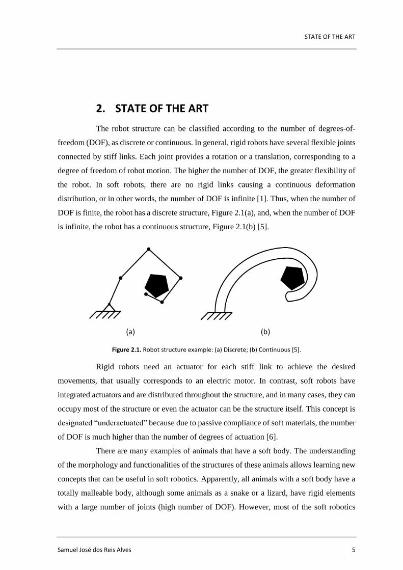
is infinite, the robot has a continuous structure, Figure 2.1(b) [5].
Figure 2.1. Robot structure example: (a) Discrete; (b) Continuous [5].
Rigid robots need an actuator for each stiff link to achieve the desired
movements, that usually corresponds to an electric motor. In contrast, soft robots have
integrated actuators and are distributed throughout the structure, and in many cases, they can
occupy most of the structure or even the actuator can be the structure itself. This concept is
designated “underactuated” because due to passive compliance of soft materials, the number
of DOF is much higher than the number of degrees of actuation [6].
There are many examples of animals that have a soft body. The understanding
of the morphology and functionalities of the structures of these animals allows learning new
concepts that can be useful in soft robotics. Apparently, all animals with a soft body have a
totally malleable body, although some animals as a snake or a lizard, have rigid elements
with a large number of joints (high number of DOF). However, most of the soft robotics
(a) (b)

Design and manufacturing of soft robotics mechanisms: improving the reliability of pneumatic-based solutions
6 2020
studies focus on animals without rigid elements, such as the octopus, that has only
hydrostatics muscles (infinite DOF) (Figure 2.2(a)).
The octopus is one of the first examples of inspiration in this area because it has
eight arms composed of hydrostatic muscles, which provide excellent adaptation,
deformation, locomotion and grasping skills towards his environment. Each arm is
composed of three types of muscles groups: longitudinal, transversal and oblique, changing
the length of the arm, bending in all directions and twisting (Figure 2.2 (b)).
Figure 2.2. Biological inspiration. (a) Octopus arm; (b) Scheme of the muscle arrangement of the octopus arm [4].
The elongation of the arm occurs according to the contraction of the transverse
muscles (T), that is when the diameter of the muscle decreases and consequently, the length
increases. Bending happens when the longitudinal muscles (L) on the one side of the arm
are contracted, and after that, the transverse muscles are too. The twist results from the
contraction of the oblique muscles (O). Furthermore, the arrangement of these muscles
allows combined contractions, varying the stiffness of the arms and achieved high values of
force [4]. Other examples of hydrostatic muscles are the elephant trunk (Figure 2.3(a)), the
arms and tentacles of the squid (Figure 2.3(b)), and the dog tongue (Figure 2.3(c)). [1]
Figure 2.3. Examples of hydrostatic muscles. (a) The elephant trunk; (b) The arms and tentacles of squid; (c) The dog tongue [1].
(a) (b)
(a) (c)(b)

STATE OF THE ART
Samuel José dos Reis Alves 7
2.1. Types of Actuators
Soft robots are commonly actuated by variable-length tendons or
pneumatic/hydraulic actuation. In the first case, the variation occurs in the form of tension
cables or shape-memory alloy actuators (SMA)[7]. Based on this approach, a prototype of a
robotic octopus arm was made, with the actuation obtained through cables (longitudinally)
and SMAs springs (transversely)[4].
Figure 2.4. Octopus robot arm with cables and SMAs springs [4].
In the second case, the pneumatic actuation consists of inflating channels in soft
materials causing the desired deformations. Within this type of actuation, many actuators
have been developed. Pneumatic artificial muscles, also known as McKibben actuators, were
developed in the 1950s and 1960s to develop artificial muscles [8]. These muscles contain a
flexible elastomer tube with reinforcement of braided fibres, being closed at the ends. The
fibre arrangement is placed so that, when the actuator is pressurized, transverse expansion
and longitudinal contraction occur (volume conservation). Another type is the fluidic
elastomer actuator, an actuator made of low hardness rubber and driven by a relatively low-
pressure fluid. It can be divided into three types according to their geometry: pleated, ribbed
and cylindrical [9].
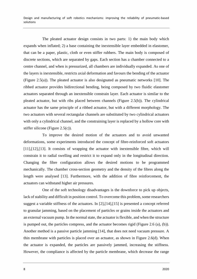
Figure 2.5. Three types of fluidic elastomer actuators. (a) Pleated; (b) Ribbed; (c) Cylindrical; (1) unactuated state; (2) actuated state [9].
(a.2) (b.2) (c.2)
(a.1) (c.1)(b.1)
Design and manufacturing of soft robotics mechanisms: improving the reliability of pneumatic-based solutions
8 2020
The pleated actuator design consists in two parts: 1) the main body which
expands when inflated; 2) a base containing the inextensible layer embedded in elastomer,
that can be a paper, plastic, cloth or even stiffer rubbers. The main body is composed of
discrete sections, which are separated by gaps. Each section has a chamber connected to a
centre channel, and when is pressurized, all chambers are individually expanded. As one of
the layers is inextensible, restricts axial deformation and favours the bending of the actuator
(Figure 2.5(a)). The pleated actuator is also designated as pneumatic networks [10]. The
ribbed actuator provides bidirectional bending, being composed by two fluidic elastomer
actuators separated through an inextensible constrain layer. Each actuator is similar to the
pleated actuator, but with ribs placed between channels (Figure 2.5(b)). The cylindrical
actuator has the same principle of a ribbed actuator, but with a different morphology. The
two actuators with several rectangular channels are substituted by two cylindrical actuators
with only a cylindrical channel, and the constraining layer is replaced by a hollow core with
stiffer silicone (Figure 2.5(c)).
To improve the desired motion of the actuators and to avoid unwanted
deformations, some experiments introduced the concept of fibre-reinforced soft actuators
[11],[12],[13]. It consists of wrapping the actuator with inextensible fibre, which will
constrain it to radial swelling and restrict it to expand only in the longitudinal direction.
Changing the fibre configuration allows the desired motions to be programmed
mechanically. The chamber cross-section geometry and the density of the fibres along the
length were analysed [13]. Furthermore, with the addition of fibre reinforcement, the
actuators can withstand higher air pressures.
One of the soft technology disadvantages is the downforce to pick up objects,
lack of stability and difficult in position control. To overcome this problem, some researchers
suggest a variable stiffness of the actuators. In [2],[14],[15] is presented a concept referred
to granular jamming, based on the placement of particles or grains inside the actuators and
an external vacuum pump. In the normal state, the actuator is flexible, and when the structure
is pumped out, the particles compress, and the actuator becomes rigid (Figure 2.6 (a), (b)).
Another method is a passive particle jamming [14], that does not need vacuum pressure. A
thin membrane with particles is placed over an actuator, as shown in Figure 2.6(d). When
the actuator is expanded, the particles are passively jammed, increasing the stiffness.
However, the compliance is affected by the particle membrane, which decrease the range
STATE OF THE ART
Samuel José dos Reis Alves 9
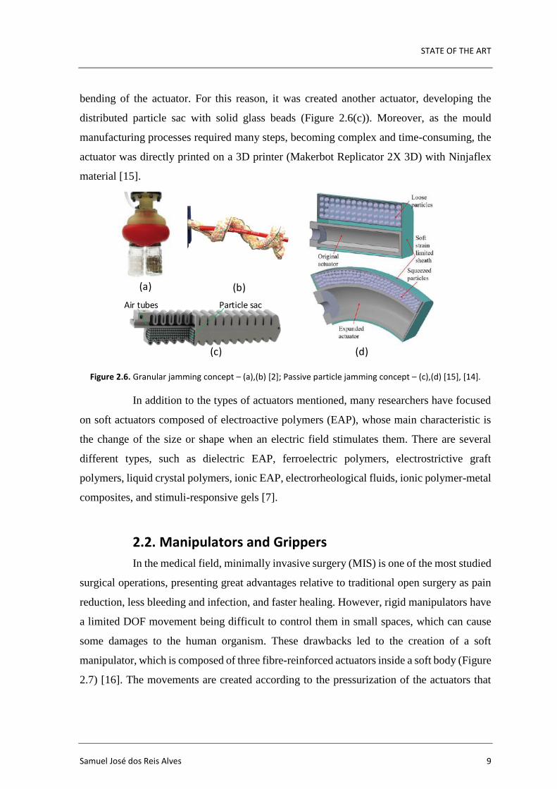
bending of the actuator. For this reason, it was created another actuator, developing the
distributed particle sac with solid glass beads (Figure 2.6(c)). Moreover, as the mould
manufacturing processes required many steps, becoming complex and time-consuming, the
actuator was directly printed on a 3D printer (Makerbot Replicator 2X 3D) with Ninjaflex
material [15].
Figure 2.6. Granular jamming concept – (a),(b) [2]; Passive particle jamming concept – (c),(d) [15], [14].
In addition to the types of actuators mentioned, many researchers have focused
on soft actuators composed of electroactive polymers (EAP), whose main characteristic is
the change of the size or shape when an electric field stimulates them. There are several
different types, such as dielectric EAP, ferroelectric polymers, electrostrictive graft
polymers, liquid crystal polymers, ionic EAP, electrorheological fluids, ionic polymer-metal
composites, and stimuli-responsive gels [7].
2.2. Manipulators and Grippers
In the medical field, minimally invasive surgery (MIS) is one of the most studied
surgical operations, presenting great advantages relative to traditional open surgery as pain
reduction, less bleeding and infection, and faster healing. However, rigid manipulators have
a limited DOF movement being difficult to control them in small spaces, which can cause
some damages to the human organism. These drawbacks led to the creation of a soft
manipulator, which is composed of three fibre-reinforced actuators inside a soft body (Figure
2.7) [16]. The movements are created according to the pressurization of the actuators that
(a) (b)
(c) (d)
Particle sacAir tubes

Design and manufacturing of soft robotics mechanisms: improving the reliability of pneumatic-based solutions
10 2020
are equally distributed. Other examples of application to the same purpose are reported in
[17] and [18].
Figure 2.7. Soft surgical manipulator. (a) One fibre-reinforced actuator pressurized; (b) Internal design. (FFA – flexible fluidic actuator) [16].
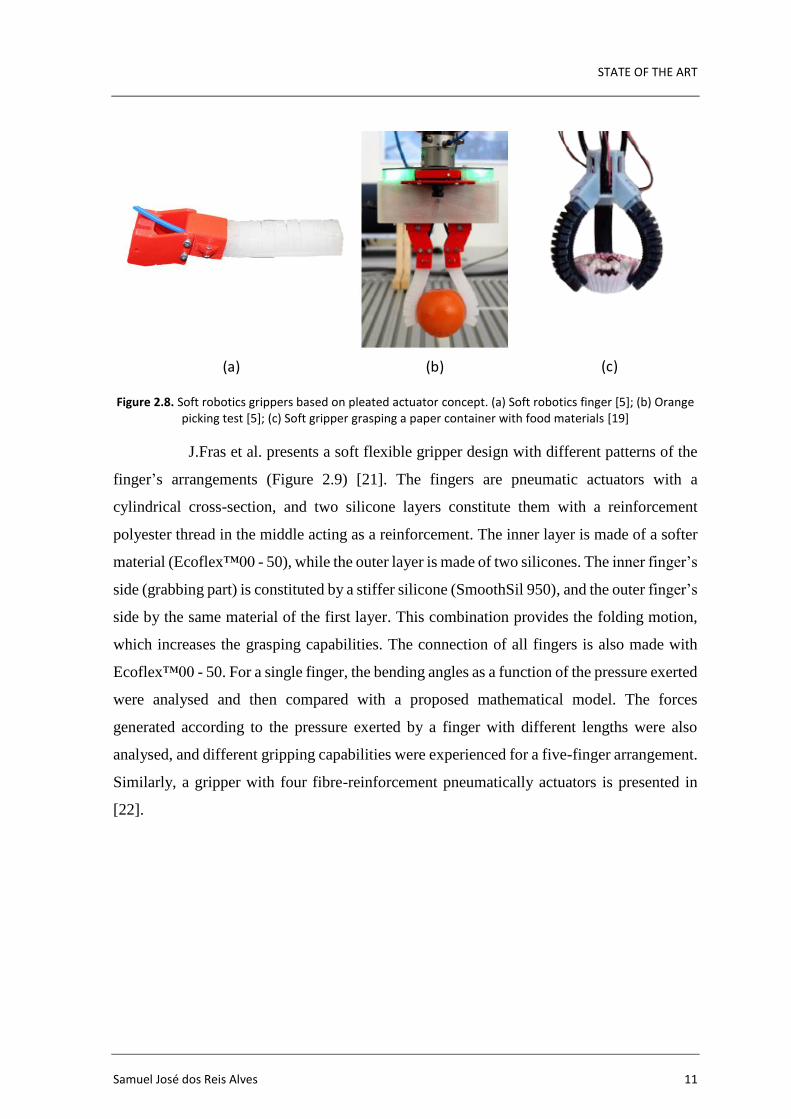
During the 2018-2019 school year, based on the pleated actuator, it was
developed in the Mechanical Engineering Department of the University of Coimbra, two
soft robotics fingers for a collaborative gripper [5]. Each finger has a rigid part that was
made with polylactic acid (PLA) material using a 3D printer, and an actuator made of a
silicone rubber (Ecoflex™ 00-30) into a mould which was also produced on a 3D printer
(Figure 2.8(a), (b)). The soft robotics fingers achieved good capacity to conform the fingers
to the object’s surfaces and pick-up objects. However, some problems occurred when the
soft fingers were used to lift heavier objects. That happened because when more pressure
was needed to inflate the fingers, air bubbles appeared due to the low thickness of the fingers.
Similar work was developed in [19],[20] for studying grasping and lifting a paper container
with food materials. The gripper is composed of three fingers made directly from the 3D
printer (Object260connex) with a soft rubber-like (TangoBlack +).
(a) (b)
STATE OF THE ART
Samuel José dos Reis Alves 11
Figure 2.8. Soft robotics grippers based on pleated actuator concept. (a) Soft robotics finger [5]; (b) Orange picking test [5]; (c) Soft gripper grasping a paper container with food materials [19]
J.Fras et al. presents a soft flexible gripper design with different patterns of the
finger’s arrangements (Figure 2.9) [21]. The fingers are pneumatic actuators with a
cylindrical cross-section, and two silicone layers constitute them with a reinforcement
polyester thread in the middle acting as a reinforcement. The inner layer is made of a softer
material (Ecoflex™00 - 50), while the outer layer is made of two silicones. The inner finger’s
side (grabbing part) is constituted by a stiffer silicone (SmoothSil 950), and the outer finger’s
side by the same material of the first layer. This combination provides the folding motion,
which increases the grasping capabilities. The connection of all fingers is also made with
Ecoflex™00 - 50. For a single finger, the bending angles as a function of the pressure exerted
were analysed and then compared with a proposed mathematical model. The forces
generated according to the pressure exerted by a finger with different lengths were also
analysed, and different gripping capabilities were experienced for a five-finger arrangement.
Similarly, a gripper with four fibre-reinforcement pneumatically actuators is presented in
[22].
(a) (b) (c)

Design and manufacturing of soft robotics mechanisms: improving the reliability of pneumatic-based solutions
12 2020
Figure 2.9. Grippers with different fingers arrangements. (a) Five fingers; (b) Four fingers; (c) Inspired by the human hand [21].
A fabric-based lightweight robotic gripper [23] is actuated by pneumatic
pressure. The fingers are made of an airtight fabric with a pleated structure on one side of
the finger. During pressurization, the pleats unfold while one the other side remains with the
same length, causing deformation of the finger.
Figure 2.10. A fabric-based lightweight robotic gripper with two fingers [23].
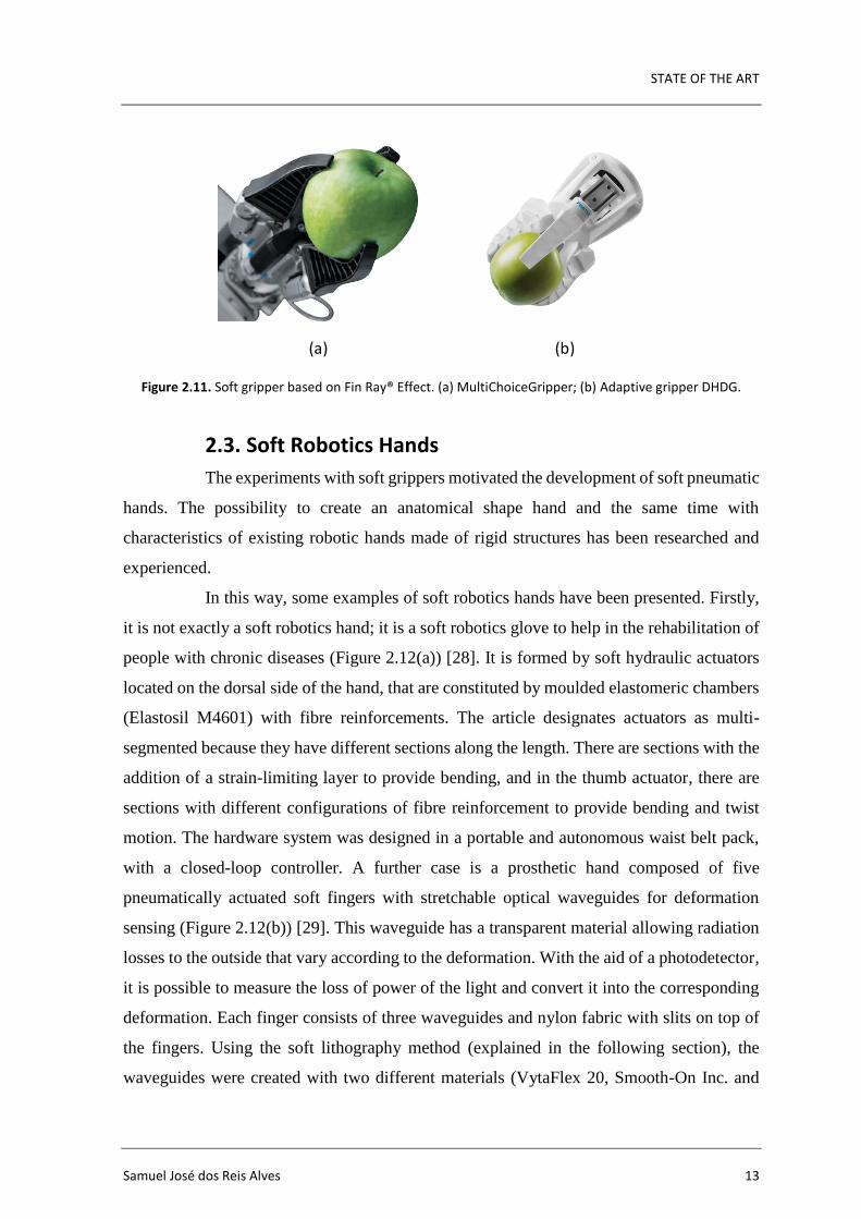
A different gripper without actuation of soft components, but with interest
features, is the Fin Ray® Effect discovered by biologist Leif Kniese of Evologics GmbH,
which is inspired by the physiology of fish fins [24]. The gripper fingers have a triangular
structure with crossbeams that deform when pressed in opposition to the object, reaching the
necessary compliance to pick up the object. The great results of this investigation led to the
application of this methodology in Festo's grippers, such as MultiChoiceGripper [25] and
the adaptive gripper DHDG [26]. In addition, some improvements have been made to create
desired bending directions in order to require less force to obtain good adhesions on an object
[27].
(a) (b) (c)
STATE OF THE ART
Samuel José dos Reis Alves 13
Figure 2.11. Soft gripper based on Fin Ray® Effect. (a) MultiChoiceGripper; (b) Adaptive gripper DHDG.
2.3. Soft Robotics Hands
The experiments with soft grippers motivated the development of soft pneumatic
hands. The possibility to create an anatomical shape hand and the same time with
characteristics of existing robotic hands made of rigid structures has been researched and
experienced.
In this way, some examples of soft robotics hands have been presented. Firstly,
it is not exactly a soft robotics hand; it is a soft robotics glove to help in the rehabilitation of
people with chronic diseases (Figure 2.12(a)) [28]. It is formed by soft hydraulic actuators
located on the dorsal side of the hand, that are constituted by moulded elastomeric chambers
(Elastosil M4601) with fibre reinforcements. The article designates actuators as multi-
segmented because they have different sections along the length. There are sections with the
addition of a strain-limiting layer to provide bending, and in the thumb actuator, there are
sections with different configurations of fibre reinforcement to provide bending and twist
motion. The hardware system was designed in a portable and autonomous waist belt pack,
with a closed-loop controller. A further case is a prosthetic hand composed of five
pneumatically actuated soft fingers with stretchable optical waveguides for deformation
sensing (Figure 2.12(b)) [29]. This waveguide has a transparent material allowing radiation
losses to the outside that vary according to the deformation. With the aid of a photodetector,
it is possible to measure the loss of power of the light and convert it into the corresponding
deformation. Each finger consists of three waveguides and nylon fabric with slits on top of
the fingers. Using the soft lithography method (explained in the following section), the
waveguides were created with two different materials (VytaFlex 20, Smooth-On Inc. and
(a) (b)

Design and manufacturing of soft robotics mechanisms: improving the reliability of pneumatic-based solutions
14 2020
ELASTOSIL M 4601 A/B, Wacker Chemie AG), and the body of the fingers with silicone
(Ecoflex™ 00 - 30). The palm of the hand was created by a 3D printer with a rigid material.
Deimel and Brock proposed the RBO Hand 2 (Figure 2.12(c)) [6]. It is a
passively compliant and underactuated robotic hand that provides simpler controls, easy
manufacturing and dexterous grasping. It is composed of seven pneumatic continuum
actuators, called Pneuflex, five of them correspond to the fingers and the remaining two to
the palm.
Figure 2.12. Three different concepts of soft robotics hands. (a) Soft robotics glove [28]; (b) Soft prosthetic hand via stretchable optical waveguides [29]; (c) The RBO Hand 2 [6].
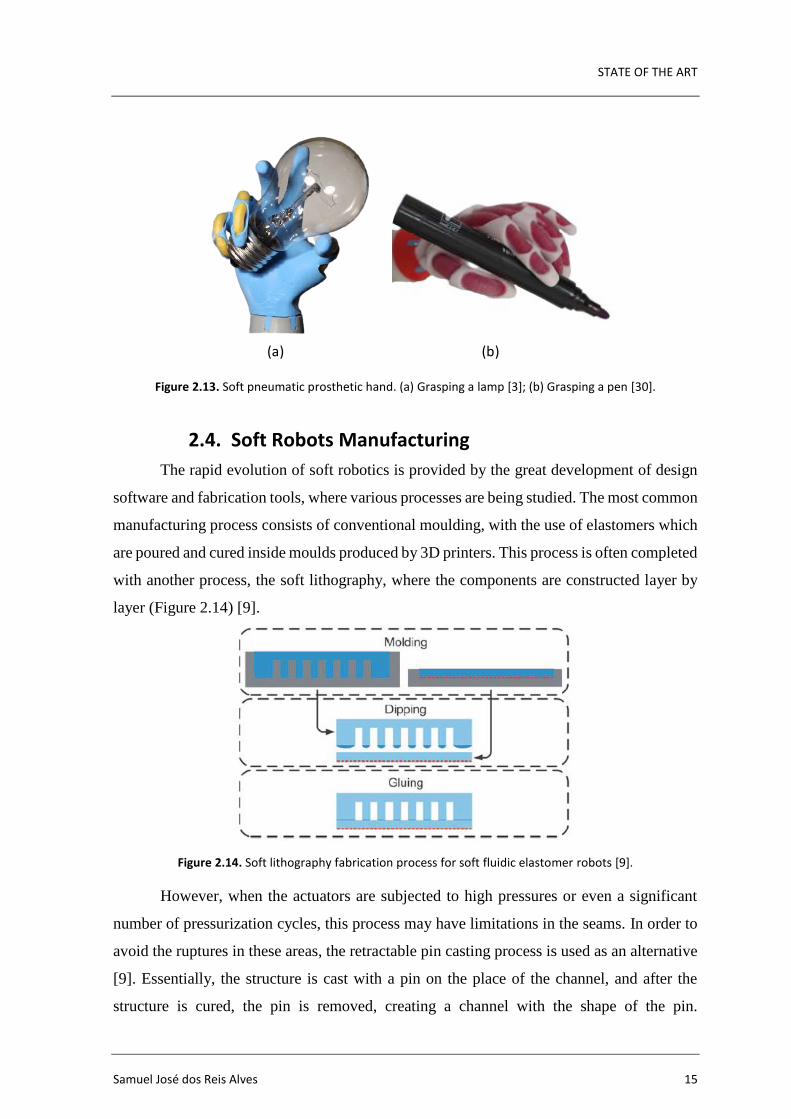
Finally, Fras and Althoefer presented the soft pneumatic prosthetic hand
[3],[30], with an appearance more similar to the real hand of a child (Figure 2.13(b),(c)).
This hand has six actuators (fibre-reinforced conical actuator) and an exoskeleton structure
that constrains the deformations of the actuators in the desired areas to led the actuator to
move to the free areas (fingers joints) providing the bending motion. Each finger has one
actuator and the thumb has two, to achieve the opposition and reposition motion. The
manufacturing is made by pouring silicone material into the 3D printed moulds, providing a
reduced cost. The actuators are built with soft silicone SmoothOn EcoFlex™ 00-50 and the
exoskeleton with a stiffer silicone SmootOn SmoothSill 940. The actuators are driven by
pneumatic pressure, from a control unit constituted by a Raspberry Pi computer and six
solenoid valves, that are controlled independently with pulse width modulation (PWM)
signals. This control unit can be executed by a joystick or using leapmotion controller, which
consists of imitating the operator's hand. Some tests showed that the hand can perform
several movements and it is capable to grasping various objects.
(a) (b) (c)
STATE OF THE ART
Samuel José dos Reis Alves 15
Figure 2.13. Soft pneumatic prosthetic hand. (a) Grasping a lamp [3]; (b) Grasping a pen [30].
2.4. Soft Robots Manufacturing
The rapid evolution of soft robotics is provided by the great development of design
software and fabrication tools, where various processes are being studied. The most common
manufacturing process consists of conventional moulding, with the use of elastomers which
are poured and cured inside moulds produced by 3D printers. This process is often completed
with another process, the soft lithography, where the components are constructed layer by
layer (Figure 2.14) [9].
Figure 2.14. Soft lithography fabrication process for soft fluidic elastomer robots [9].
However, when the actuators are subjected to high pressures or even a significant
number of pressurization cycles, this process may have limitations in the seams. In order to
avoid the ruptures in these areas, the retractable pin casting process is used as an alternative
[9]. Essentially, the structure is cast with a pin on the place of the channel, and after the
structure is cured, the pin is removed, creating a channel with the shape of the pin.
(a) (b)
Design and manufacturing of soft robotics mechanisms: improving the reliability of pneumatic-based solutions
16 2020
Nevertheless, to be able to remove the pin, the channel structures of the actuators need to be
relatively simple, also creating a limitation. Thus, to prevent the problem of seams and
simple channels, the lost wax casting method has been proposed, where the space of the
structure channels is filled with wax, and after the structure is cured, the wax can be melted
and removed, creating the channels [31]. Even so, the structures produced are limited to
those that allow the removable material to drain.
Looking at the processes described above, despite allowing the production of soft
robots, they all require a lot of labour and time, reducing accuracy and repeatability. To make
soft robotics level up, it is necessary to go further, as Walker et al. points out: “In order for
soft robotics to gain foothold in industrial, military, and consumer spaces, production must
move beyond existing methods. Soft robot fabrication technology must become automated
and robots must be easily created at a relatively low cost and on large scale” [32]. Following
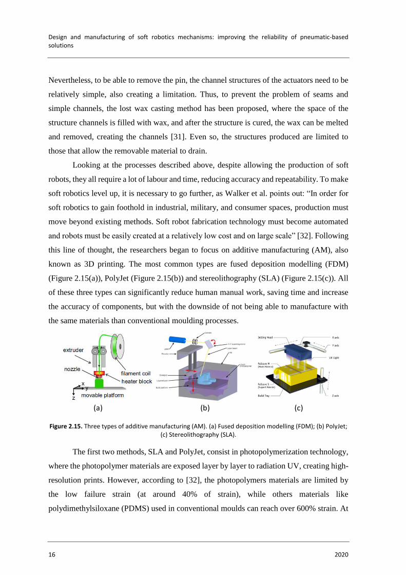
this line of thought, the researchers began to focus on additive manufacturing (AM), also
known as 3D printing. The most common types are fused deposition modelling (FDM)
(Figure 2.15(a)), PolyJet (Figure 2.15(b)) and stereolithography (SLA) (Figure 2.15(c)). All
of these three types can significantly reduce human manual work, saving time and increase
the accuracy of components, but with the downside of not being able to manufacture with
the same materials than conventional moulding processes.
Figure 2.15. Three types of additive manufacturing (AM). (a) Fused deposition modelling (FDM); (b) PolyJet; (c) Stereolithography (SLA).
The first two methods, SLA and PolyJet, consist in photopolymerization technology,
where the photopolymer materials are exposed layer by layer to radiation UV, creating high-
resolution prints. However, according to [32], the photopolymers materials are limited by
the low failure strain (at around 40% of strain), while others materials like
polydimethylsiloxane (PDMS) used in conventional moulds can reach over 600% strain. At
(a) (b) (c)
STATE OF THE ART
Samuel José dos Reis Alves 17
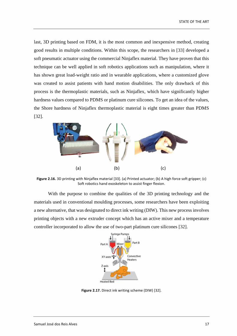
last, 3D printing based on FDM, it is the most common and inexpensive method, creating
good results in multiple conditions. Within this scope, the researchers in [33] developed a
soft pneumatic actuator using the commercial Ninjaflex material. They have proven that this
technique can be well applied in soft robotics applications such as manipulation, where it
has shown great load-weight ratio and in wearable applications, where a customized glove
was created to assist patients with hand motion disabilities. The only drawback of this
process is the thermoplastic materials, such as Ninjaflex, which have significantly higher
hardness values compared to PDMS or platinum cure silicones. To get an idea of the values,
the Shore hardness of Ninjaflex thermoplastic material is eight times greater than PDMS
[32].
Figure 2.16. 3D printing with Ninjaflex material [33]. (a) Printed actuator; (b) A high force soft gripper; (c) Soft robotics hand exoskeleton to assist finger flexion.
With the purpose to combine the qualities of the 3D printing technology and the
materials used in conventional moulding processes, some researchers have been exploiting
a new alternative, that was designated to direct ink writing (DIW). This new process involves
printing objects with a new extruder concept which has an active mixer and a temperature
controller incorporated to allow the use of two-part platinum cure silicones [32].
Figure 2.17. Direct ink writing scheme (DIW) [32].
(a) (b) (c)
Design and manufacturing of soft robotics mechanisms: improving the reliability of pneumatic-based solutions
18 2020
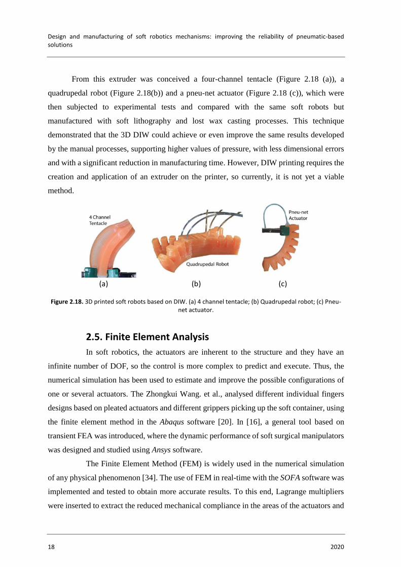
From this extruder was conceived a four-channel tentacle (Figure 2.18 (a)), a
quadrupedal robot (Figure 2.18(b)) and a pneu-net actuator (Figure 2.18 (c)), which were
then subjected to experimental tests and compared with the same soft robots but
manufactured with soft lithography and lost wax casting processes. This technique
demonstrated that the 3D DIW could achieve or even improve the same results developed
by the manual processes, supporting higher values of pressure, with less dimensional errors
and with a significant reduction in manufacturing time. However, DIW printing requires the
creation and application of an extruder on the printer, so currently, it is not yet a viable
method.
Figure 2.18. 3D printed soft robots based on DIW. (a) 4 channel tentacle; (b) Quadrupedal robot; (c) Pneu-net actuator.
2.5. Finite Element Analysis
In soft robotics, the actuators are inherent to the structure and they have an
infinite number of DOF, so the control is more complex to predict and execute. Thus, the
numerical simulation has been used to estimate and improve the possible configurations of
one or several actuators. The Zhongkui Wang. et al., analysed different individual fingers
designs based on pleated actuators and different grippers picking up the soft container, using
the finite element method in the Abaqus software [20]. In [16], a general tool based on
transient FEA was introduced, where the dynamic performance of soft surgical manipulators
was designed and studied using Ansys software.
The Finite Element Method (FEM) is widely used in the numerical simulation
of any physical phenomenon [34]. The use of FEM in real-time with the SOFA software was
implemented and tested to obtain more accurate results. To this end, Lagrange multipliers
were inserted to extract the reduced mechanical compliance in the areas of the actuators and
(a) (b) (c)

STATE OF THE ART
Samuel José dos Reis Alves 19
the end-effector position, and a constrained-based approach was solved by an iterative
algorithm to find the contribution of the actuators in the deformation of the structure [35].
Still in SOFA software, an opensource for multi-materials simulations was recently
launched, to facilitate the modelling of soft robots with different materials. It consists of a
set of tools to help users to design partitioned tetrahedral meshes, with the aim of a single
mesh to have different properties [36]. Gunjan Agarwal et al. [37] implemented a numerical
method where the actuators under study are reinforced with an un-stretchable shell. Two
different prototypes were studied (linear and bending actuators), consisting of a majority
component with the elastomer Ecoflex™ 00-30 and an un-stretchable shell made of
polyethylene terephthalate (PET). The numerical models were used to predict the actuator
behaviour in large strains in order to execute design iterations for optimizations. Then the
prototypes were subjected to experimental tests of free displacement and blocked forces,
where the numerical models were validated.
In another context, the use of soft sensors is very important to obtain feedback
regarding the control of soft robots. Nonetheless, obtaining feedback from these sensors is a
tricky task due to the infinite number of DOF. For a better understanding, a soft capacitive
sensor was placed inside of a soft pneumatic actuator, and with the aid of the development
of a finite element model using the COMSOL software, it was studied how pressure, force
and stretch influence the change in the capacitance of the sensor [38].

Design and manufacturing of soft robotics mechanisms: improving the reliability of pneumatic-based solutions
20 2020

SOFT ROBOTICS HAND CONCEPT
Samuel José dos Reis Alves 21
3. SOFT ROBOTICS HAND CONCEPT
3.1. Human Hand Anatomy
In order to obtain a robotic hand, which executes as many tasks as possible and
ideally looks like a real hand, the study of some concepts of human hand anatomy is required.
The finger movements are produced by different muscles that are located in the hand
and forearm. The forearm muscles narrow into tendons until they reach various points on the
finger bones. Although the concepts related to muscles and nerves are quite important to
understand the whole kinematics of the hand, in this dissertation, these contents will not be
developed. The focus is only on the bones and their joints because these structures can reach
the dexterity of the hand.
3.1.1. Bones and Joints
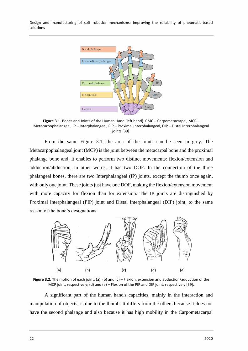
The human hand is composed of several bones with multiple joints (Figure 3.1)
giving a vast number of movements with a high degree of stability, precision, strength and
flexibility. This bone structure begins at the root of the hand, i.e. the wrist zone, which is
composed of eight grouped bones, called carpals bones. The remaining posterior bones
correspond to the composition of the fingers, containing metacarpals and phalangeal bones.
Each finger presents one metacarpal bone and three phalanges, except the thumb that only
presents one metacarpal bone and two phalanges bones. The metacarpal bone is the bone
closer to the wrist, and the phalanges bones are divided into proximal, intermediate and distal
phalange. The proximal phalange, according to the name, is the bone closer to the
metacarpals, the intermediate bone is the middle and the distal bone is the last finger bone.
In the case of the thumb, the intermediate bone does not exist.
Design and manufacturing of soft robotics mechanisms: improving the reliability of pneumatic-based solutions
22 2020
Figure 3.1. Bones and Joints of the Human Hand (left hand). CMC – Carpometacarpal, MCP – Metacarpophalangeal, IP – Interphalangeal, PIP – Proximal Interphalangeal, DIP – Distal Interphalangeal
joints [39].
From the same Figure 3.1, the area of the joints can be seen in grey. The
Metacarpophalangeal joint (MCP) is the joint between the metacarpal bone and the proximal
phalange bone and, it enables to perform two distinct movements: flexion/extension and
adduction/abduction, in other words, it has two DOF. In the connection of the three
phalangeal bones, there are two Interphalangeal (IP) joints, except the thumb once again,
with only one joint. These joints just have one DOF, making the flexion/extension movement
with more capacity for flexion than for extension. The IP joints are distinguished by
Proximal Interphalangeal (PIP) joint and Distal Interphalangeal (DIP) joint, to the same
reason of the bone’s designations.
Figure 3.2. The motion of each joint; (a), (b) and (c) – Flexion, extension and abduction/adduction of the MCP joint, respectively; (d) and (e) – Flexion of the PIP and DIP joint, respectively [39].
A significant part of the human hand's capacities, mainly in the interaction and
manipulation of objects, is due to the thumb. It differs from the others because it does not
have the second phalange and also because it has high mobility in the Carpometacarpal

SOFT ROBOTICS HAND CONCEPT
Samuel José dos Reis Alves 23
(CMC) joint. Unlike the CMC joint of the other fingers that have one DOF, the CMC joint
of the thumb contains two DOF allowing flexion/extension and abduction/adduction. The
MCP joint allows just like the other fingers to have two DOF, but with the advantage of the
thumb to have a greater range of adduction/abduction angle. The IP joint just has one DOF.
In this way, the thumb allows several movements as represented in Figure 3.3[39][40].
Figure 3.3. Thumb Movement Types [41].
3.1.2. Actuation Strategies
A recent study reports how the actuation strategy for underactuated hands affects
the ability of a hand to grasp different objects and mimic the movements of fingers
(anthropomorphism) [39]. In a first phase, the various grasps used by the human hand were
studied, describing the existence of 33 different grasps [42]. Also, the most frequently used
positions in daily life were studied. Then, 16 possible actuation configurations were defined,
from 1 to 5 actuators and the positions of grasping objects that each strategy could achieve
were analysed. The study consisted in determining which configuration achieves the most
grasps, but also determining which configuration achieves the highest percentage of top10
grasps. In a second phase, a study about which configuration achieves the highest
anthropomorphism index was carried out.
In a first conclusion, a larger number of actuators leads to better performance,
however, the higher number, the more difficult it is in terms of space, control complexity,
hand weight and cost. In a second conclusion, it has been described that it is advantageous
to actuate the middle, ring and little finger simultaneously, and act the thumb and index
finger independently. Also, the option of using an independent actuator for thumb
abduction/adduction movement proved to be quite important for the actuation strategies.

Design and manufacturing of soft robotics mechanisms: improving the reliability of pneumatic-based solutions
24 2020
3.2. System Requirements
According to the bibliographic review, there is potential to create a robotic hand
with only soft materials, without metallic components, resembling the shape of a real hand,
improving patient safety and improving compliance with different objects. Thus, in this
dissertation, a robotic hand will be presented, where the main requirement will be the use of
soft materials.
The development of the soft robotics hand consists of two main components: the
structure and the fibre-reinforced actuators. The exoskeleton defines the hand structure, and
the fibre-reinforced actuators will be inside of the finger’s structure. The hand structure will
be made of a stiffer material compared to the actuator, but it still would be a flexible/soft
material. The fibre-reinforced actuators will be composed of an elastomer, which is a
stretchable material with excellent flexion properties and high deformation capabilities, and
another component will correspond to a polyethylene terephthalate (PET) helical thread, also
known as polyester. This thread will be inserted in the middle of two layers of elastomer,
operating as a reinforcement (Figure 3.4(a)). When the actuator is pressurized, the
reinforcement prevents radial deformation, allowing only longitudinal deformation. The
structure offers a configuration that allows constraining the deformation of the actuator in
the area of the human hand bones, except in the area of the finger joints (Figure 3.4(b)). As
the structure will also be closed at the fingertip, the longitudinal deformation of the fingertip
will be constrained, and the actuators tend to expand to the free areas (finger joints),
converting the longitudinal motion into a bending motion. This concept is based on the work
of Jan Fras and Kaspar Althoefer [3][30], which has proved to be successful in grasping
capabilities and manipulation tasks. However, here the manufacture of the hand structure is
implemented by 3D printing.
The hand will have seven actuators, and they could be controlled independently,
but also, they could be controlled in groups (synergistically) to reduce the control
requirements. Each finger will be composed of one actuator, and the thumb will be composed
of three, one for the flexion motion and two for the opposition/reposition motion. When the
two thumb actuators are actuated, the opposition motion will be created, and when they are
not actuated, the reposition motion occurs. They will be placed in the palm, close to the
thumb, restricted on the tips and the palm side. As the palm side restriction will have a thin

SOFT ROBOTICS HAND CONCEPT
Samuel José dos Reis Alves 25
thickness, and only the upper part will be freedom, when pressurized, the actuator tends to
expand to the upper part, creating a bending motion (Figure 3.4 (c)).
Figure 3.4. Concept of the soft hand fingers. (a) Fibre-reinforced actuator; (b) Finger exoskeleton;(c) Opposition/reposition thumb actuators.
3.3. Manufacturing
The manufacturing processes used will be the FDM and the pin casting, for the
exoskeleton and the actuators, respectively. Both processes require a 3D printer, but with
different purposes. For the first process, it will be used to 3D print directly the exoskeleton
of the hand with flexible materials. In the second process, it will be used for the creation of
the moulds that serve as auxiliary tools for the creation of the actuators.
The design of the hand and the actuators moulds are conceived using CAD
software, more specifically, the Autodesk Inventor 2020. With the variety of tools that the
program offers, it is possible to approximate the proposed hand to a real hand. The
complexity of the hand would create difficulty in changing measures to create suitable
External Elastomer layer
Internal Elastomer layer
PET reinforcement
Air chamber
B B
SECTION BB
3D printing part 13D printing part 2
A
SECTION AA(b)
Finger joint area
A
A
Finger bones area
Actuator
A
SECTION AA
Not actuated Actuated
Air tubesTwo actuators
Palm side
Exoskeleton
(a)

Design and manufacturing of soft robotics mechanisms: improving the reliability of pneumatic-based solutions
26 2020
actuators and to make comparisons of results. Also, the high number of details of a real hand,
in FEA, creates a high number of meshes that consequently would take many hours to run a
simulation and therefore increases the likelihood of errors. For these reasons, the 3D
scanning will not be used. The CAD file is saved in stereolithographic (STL) format, which
is a file that only describes the geometrical surface of a 3D object, and this file is essential
because the slicer software (next step) requires this type of format. After obtaining the STL
file, it is loaded into the slicer software called Ultimaker Cura. This software slices the model
into horizontal layers with the trajectories that the 3D printer needs to perform in order to
build the object. After the successful slicing, the data is then saved in g-code format and
transferred to the 3D printer, in this specific case, BQ Hephestos 2.
3.3.1. Materials
3.3.1.1. Elastomers
Elastomers are polymeric materials that when submitted to mechanical
stresses, can highly deform and when the stress is removed, can return to the initial format
(or almost). There are many types of elastomer materials such as natural rubber, synthetic
polyisoprene, styrene-butadiene rubber, nitrile rubbers, polychloroprene and silicones.
Among all types of elastomers, the only one referenced in this document is the silicones,
once they will be the only ones used in the manufacture of the actuators. Silicone rubbers
can operate in a wide temperature range (-100 ºC to 250 ºC), conceiving great advantage to
this type of elastomers.
As silicon and carbon atoms have valence 4, they can form polymer chains
through covalent bonds. Moreover, when silicon forms polymeric chains, and
simultaneously there are silicon-oxygen repeating units occupying the main chain, the
formation of silicones occurs. Between the most varied types of silicones elastomers, the
most common is that in which groups of methyl are attached to silicon, calling themselves
polydimethylsiloxane (PDMs) [42].
Recently, other types of silicones are used in soft robots. They are platinum-
catalysed silicones, highlighting the Ecoflex™ rubber and the Dragon Skin™ 30, both
produced by SmoothOn, Inc. According to the manufacturer, these silicones are suitable for
making moulds for casting but also for making prosthetic and orthotic devices [43]. The

SOFT ROBOTICS HAND CONCEPT
Samuel José dos Reis Alves 27
disadvantage of using these materials is that they are patented and exclusive to the
manufacturer, making it difficult to search for information on their composition and
chemical structure which helps to obtain the optimum conditions for manufacturing
processes. However, there are several examples in bibliographic review that allow
concluding the potential of these materials in the application of soft robots.
Table 3.1 shows the properties of three platinum-catalysed silicones, often
used in applications of soft robots. In general, if the goal is to choose a silicone with good
elongation capacity, the choice of Ecoflex™ 00-50 will be the most pertinent. However, if
the choice is the most resistant material, then Dragon Skin will be better due to the higher
tensile strength. According to Smooth-On, the hardness can be classified in three levels
(Figure 3.5), Shore hardness 00, Shore hardness A and Shore hardness D, which range from
measurements of very soft rubbers and gels to measurements of hardness of hard rubbers,
semi-rigid plastics and hard plastics [44].
Table 3.1. Technical overview of three platinum-catalysed silicone types.
Silicone types
Cure
time
[hours]
Pot
life
[min]
Density
[g/cc]
Shore
hardness
Elongation
[%]
Tensile
strength
[MPa]
Tensile
Modulus
[MPa]
Dragon Skin™ 30 16 45 1.08 30A 364 3.447 0.593
Ecoflex™ 00-30 4 45 1.07 30A 900 1.37 0.0689
Ecoflex™00-50 3 18 1.07 50A 980 2.17 0.0827
Since elongation is a crucial parameter for the finger movement requirements,
the choice should be decided between the two Ecoflex™. Comparing them, Ecoflex™ 00-
50 presents higher elongation, higher tensile strength and higher hardness. Also, the
Ecoflex™ 00-50 has a shorter cure time. So, the choice falls on the Ecoflex™ 00-50 because
it provides greater elongation and simultaneously greater tensile strength and hardness to
withstand higher pressures.
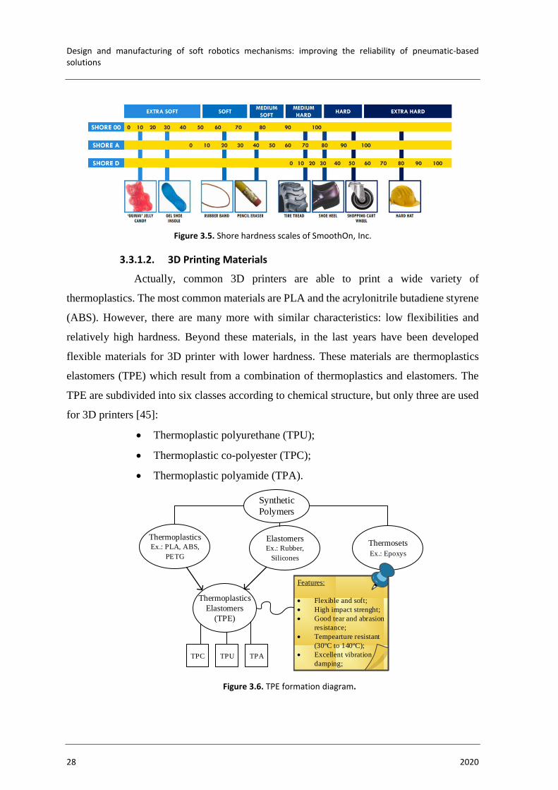
Design and manufacturing of soft robotics mechanisms: improving the reliability of pneumatic-based solutions
28 2020
Figure 3.5. Shore hardness scales of SmoothOn, Inc.
3.3.1.2. 3D Printing Materials
Actually, common 3D printers are able to print a wide variety of
thermoplastics. The most common materials are PLA and the acrylonitrile butadiene styrene
(ABS). However, there are many more with similar characteristics: low flexibilities and
relatively high hardness. Beyond these materials, in the last years have been developed
flexible materials for 3D printer with lower hardness. These materials are thermoplastics
elastomers (TPE) which result from a combination of thermoplastics and elastomers. The
TPE are subdivided into six classes according to chemical structure, but only three are used
for 3D printers [45]:
• Thermoplastic polyurethane (TPU);
• Thermoplastic co-polyester (TPC);
• Thermoplastic polyamide (TPA).
Figure 3.6. TPE formation diagram.
Synthetic
Polymers
ElastomersEx.: Rubber,
Silicones
ThermoplasticsEx.: PLA, ABS,
PETG
Thermosets
Ex.: Epoxys
Thermoplastics
Elastomers
(TPE)
TPC TPU TPA
Features:
• Flexible and soft;
• High impact strenght;
• Good tear and abrasion
resistance;
• Tempearture resistant
(30ºC to 140ºC);
• Excellent vibration
damping;

SOFT ROBOTICS HAND CONCEPT
Samuel José dos Reis Alves 29
For the exoskeleton to be able to conceive bending motions, it will be
necessary to present a higher stiffness compared to the actuator, to restrict the deformations
of the actuator in the desired places. Therefore, the choice of TPE is a good option because
it has higher stiffness than elastomers and at the same time, it has excellent flexibility
capabilities. In Table 3.2, three of the most commercialized TPE are mentioned with the
most relevant mechanical properties. There are many other models, but all of them with
similar characteristics. Of the three materials, Filaflex 95A has the highest hardness value.
The hardness value is directly related to the stiffness, and there is a need for the stiffness
value of the exoskeleton to be higher than the actuator. However, if the hardness value is
very high, consequently the stiffness value of the skeleton will also be, causing a decrease
in the bending capacity of the exoskeleton. Therefore, Filaflex 95A material may not be a
good choice and, of the three materials, it has the lowest elongation value. Between the two
remaining materials, the hardness and elongation values are similar. As for the tensile
strength, the value of Ninjaflex is lower; however, it is a value that, according to the
solicitation of the actuator will be very far from being reached. Finally, the material chosen
was Ninjaflex, not exactly because it has an advantage over Filaflex, but because the research
community provided good comments about the printing of this material. However, with pre-
existing Filaflex 82A material in the laboratory, a finger exoskeleton was printed (Section
4.1) and also proved to be an excellent option.
Table 3.2 Technical overview of three TPE materials.
Silicone types Density
[g/cc]
Shore
hardness
Elongation
[%]
Tensile
strength
[MPa]
Ninjaflex 1.19 85A 660 26
Filaflex 82A 1.12 82A 650 45
Filaflex 95A 1.00 96A 500 55

Design and manufacturing of soft robotics mechanisms: improving the reliability of pneumatic-based solutions
30 2020

DESIGN AND IMPLEMENTATION
Samuel José dos Reis Alves 31
4. DESIGN AND IMPLEMENTATION
4.1. Finger
In a first phase, the design process focused on a single finger, respecting an
iterative methodology towards continuous improvements to reach the requirements. The
requirements are: (1) design with two different components (exoskeleton and fibre-
reinforced actuator), (2) bendability, (3) use pre-existing laboratory materials (Filaflex 82A
and SmoothOn Ecoflex™ 00-30).
4.1.1. Dimensions
The finger structure was designed with an external length of approximately 86
mm and an internal length (actuator length) of 76.5 mm. The radial thickness has been
designed with 1.5 mm to offer the maximum possible flexibility. The internal diameter varies
according to the length, with the largest value of 18mm at the base and the smallest value of
13.5mm at the tip.
4.1.2. Manufacturing
4.1.2.1. Finger structure
The finger was designed in CAD and manufactured on the 3D printer, following
the steps described in Section 3.3. It was printed with Filaflex 82A material (Figure 4.1),
whose printing parameters are available in Appendix B.
Figure 4.1. Finger exoskeleton made with Filaflex 82A material. (a) Top view; (b) Front view.
4.1.2.2. Fibre-Reinforced Actuator
The fibre-reinforced actuator contains two layers of silicone Ecoflex™ 00-30
separated with a reinforcement of PET helical thread with 0.25 mm of diameter. To create
(a) (b)

Design and manufacturing of soft robotics mechanisms: improving the reliability of pneumatic-based solutions
32 2020
this concept it was necessary to develop: a mould (Figure 4.2.(a),(b),(c)), two conical cores
(Figure 4.2.(d)(e)), the preparation of the silicone mixture and a PET helical thread.
The moulds and conical cores were properly designed in CAD and printed on
the 3D printer with PLA material. Moreover, the mould and the cores were coated with XTC-
3D™ to ensure a better removal of the casting material.
Figure 4.2. PLA printed parts. (a) Mould assembly with the largest core; (b) and (c) Mould parts; (d) Largest core; (e) Smaller core.
The thread is wound around the largest core, which is then placed inside the
mould, and filled with the silicone. In this step, it was necessary to ensure that the thread
was not too tight to the core, making it easier to remove after cure. When the material is
cured, and the core is removed, as the PET does not adhere to the PLA but adheres to the
silicone, the reinforcement remains together with the silicone creating the outer layer of the
actuator. Next, for the manufacture of the inner layer, the other core is placed inside the
already created actuator layer, and then it is again filled with silicone.
Figure 4.3. Fibre-reinforced actuator.
As is observed in the mould (Figure 4.2(b), (c)), there is a small groove in order
to fit the salience of the tip of the cores to ensure centring. However, this step creates a hole
in the tip. So, after creating the inner layer, silicone was added at the tip from the inside of
the actuator to fill the empty space and create an extra thickness (2 mm).
(a) (b) (c) (d) (e)groove
salience

DESIGN AND IMPLEMENTATION
Samuel José dos Reis Alves 33
For the base of the actuator (extremity corresponding to the air pressure inlet), a
PLA part was created with a hole for the pipe connection. This part with the aid of a cable
tie allowed to prevent the air leakage (Figure 4.4). The clamp process is not the most suitable,
but as already mentioned, the purpose of the finger creation was only to test the general
requirements.
4.1.3. Testing and Results
In general, a good motion of the finger folding was observed, with a good
performance of the actuator that confirmed the potential of the PET reinforcement. Also, it
was verified that after the pressurization, the finger could return to the un-actuated state.
However, with some attempts, some leaks began to appear at the actuator tip, which was
rectified, but after some attempts, the reliability was reduced again. The reason for these
leaks comes from the manufacturing step that corresponds to centralize the core with the
mould.
Figure 4.4. Assembly of the finger exoskeleton and the fibre-reinforced actuator.
4.2. Hand
According to the finger results, it was possible to conclude that the process,
in general, has the potential to be used in the hand manufacture. In this way, the exoskeleton
was again produced by 3D printing and the actuator by the same manual method, being
applied some modifications that will be described subsequently.
4.2.1. Hand Design
The hand contains seven independent fibre-reinforced actuators, one actuator for
each finger and two actuators for opposition and reposition motion of the thumb. The size of
the hand was based on the dimensions of an adult hand, with 195 mm from the wrist to the
tip of the middle finger. The radial thickness of the finger exoskeleton has 2 mm. Compared

Design and manufacturing of soft robotics mechanisms: improving the reliability of pneumatic-based solutions
34 2020
to the finger created in the previous section, it was increased 0.5 mm to ensure that there
would be no material breakage in the most requested regions. The main remaining
dimensions of the exoskeleton and the fibre-reinforced actuators are presented in Appendix
B.
4.2.2. Manufacturing
4.2.2.1. Exoskeleton
The hand exoskeleton was printed with Ninjaflex material (Figure 4.5),
according to the choice described in Section 3.3.1.2. The printing parameters are available
in Appendix B. As the geometry of the CAD hand does not have any flat side, to print the
hand, it was necessary to activate the option to insert support material. Thus, at the end of
printing, it was necessary to remove this excess material.
Figure 4.5. Hand exoskeleton. (a) Back side; (b) Palm side.
4.2.2.2. Fibre-Reinforced Actuators
Five actuators with different sizes were constructed with the same
manufacturing procedure of the actuator mentioned in the previous section. However, there
were three significant changes:
• Changing of silicone rubber material;
• Changing of the diameter reinforcement material;
• New mould design.
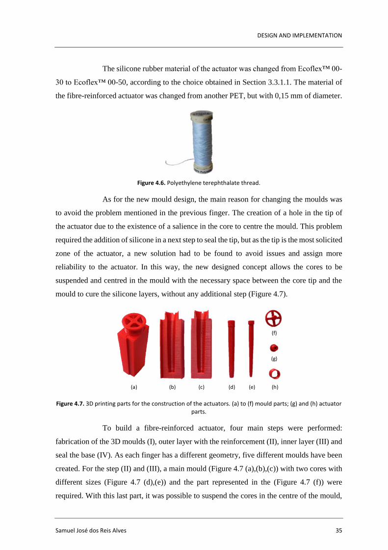
DESIGN AND IMPLEMENTATION
Samuel José dos Reis Alves 35
The silicone rubber material of the actuator was changed from Ecoflex™ 00-
30 to Ecoflex™ 00-50, according to the choice obtained in Section 3.3.1.1. The material of
the fibre-reinforced actuator was changed from another PET, but with 0,15 mm of diameter.
Figure 4.6. Polyethylene terephthalate thread.
As for the new mould design, the main reason for changing the moulds was
to avoid the problem mentioned in the previous finger. The creation of a hole in the tip of
the actuator due to the existence of a salience in the core to centre the mould. This problem
required the addition of silicone in a next step to seal the tip, but as the tip is the most solicited
zone of the actuator, a new solution had to be found to avoid issues and assign more
reliability to the actuator. In this way, the new designed concept allows the cores to be
suspended and centred in the mould with the necessary space between the core tip and the
mould to cure the silicone layers, without any additional step (Figure 4.7).
Figure 4.7. 3D printing parts for the construction of the actuators. (a) to (f) mould parts; (g) and (h) actuator parts.
To build a fibre-reinforced actuator, four main steps were performed:
fabrication of the 3D moulds (I), outer layer with the reinforcement (II), inner layer (III) and
seal the base (IV). As each finger has a different geometry, five different moulds have been
created. For the step (II) and (III), a main mould (Figure 4.7 (a),(b),(c)) with two cores with
different sizes (Figure 4.7 (d),(e)) and the part represented in the (Figure 4.7 (f)) were
required. With this last part, it was possible to suspend the cores in the centre of the mould,
(a) (b) (c) (d) (e) (h)
(g)
(f)
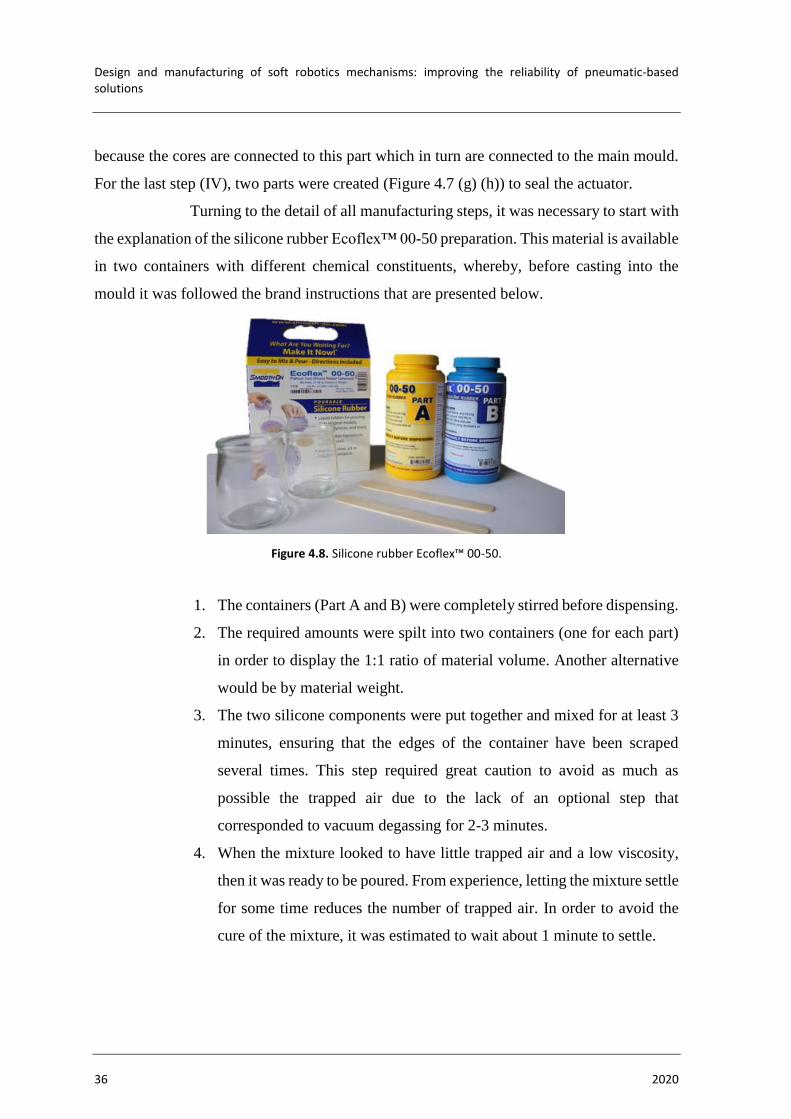
Design and manufacturing of soft robotics mechanisms: improving the reliability of pneumatic-based solutions
36 2020
because the cores are connected to this part which in turn are connected to the main mould.
For the last step (IV), two parts were created (Figure 4.7 (g) (h)) to seal the actuator.
Turning to the detail of all manufacturing steps, it was necessary to start with
the explanation of the silicone rubber Ecoflex™ 00-50 preparation. This material is available
in two containers with different chemical constituents, whereby, before casting into the
mould it was followed the brand instructions that are presented below.
Figure 4.8. Silicone rubber Ecoflex™ 00-50.
1. The containers (Part A and B) were completely stirred before dispensing.
2. The required amounts were spilt into two containers (one for each part)
in order to display the 1:1 ratio of material volume. Another alternative
would be by material weight.
3. The two silicone components were put together and mixed for at least 3
minutes, ensuring that the edges of the container have been scraped
several times. This step required great caution to avoid as much as
possible the trapped air due to the lack of an optional step that
corresponded to vacuum degassing for 2-3 minutes.
4. When the mixture looked to have little trapped air and a low viscosity,
then it was ready to be poured. From experience, letting the mixture settle
for some time reduces the number of trapped air. In order to avoid the
cure of the mixture, it was estimated to wait about 1 minute to settle.

DESIGN AND IMPLEMENTATION
Samuel José dos Reis Alves 37
Figure 4.9. Preparation of Ecoflex™ 00-50 before casting.
Between each main step of the actuator construction (II and III), it was
necessary to wait the curing time of the silicone, so the preparation described was repeated
two times. To achieve the maximum results of the material, the brand advises to cure the
material at room temperature (23 ºC) or at least to not cure it under 18 ºC. The cure time of
Ecoflex™ 00-50 is three hours and it is also recommended after the cure time at room
temperature to expose the silicone to 80ºC for 2 hours and 100 ºC for one hour, and after that
to let it cool down to room temperature again. These recommendations are adequate to
quickly reach maximum physical and performance properties.
After the silicone is ready to casting, the container is tilted slowly so that the
material pours smoothly in order to prevent the formation of new air bubbles. The material
is gradually poured so that it has time to settle down and release the trapped air.
Now explaining the procedures, the step (II) started to wrapped the PET
thread to the largest core, and after, the silicone was poured into the mould. It is important
that the thread is completely clean and whenever possible attached without the aid of any
adhesive tape, since that is enough for the layer to be poorly sealed. When the first layer was
cured, the mould was opened and the core was removed from inside of the layer. As the PET
does not adhere to the PLA but adheres to the silicone, the reinforcement remains together
with the silicone. Still, this step is the most complicated and requires great care to pull the
silicone in order to not disintegrate the reinforcement.
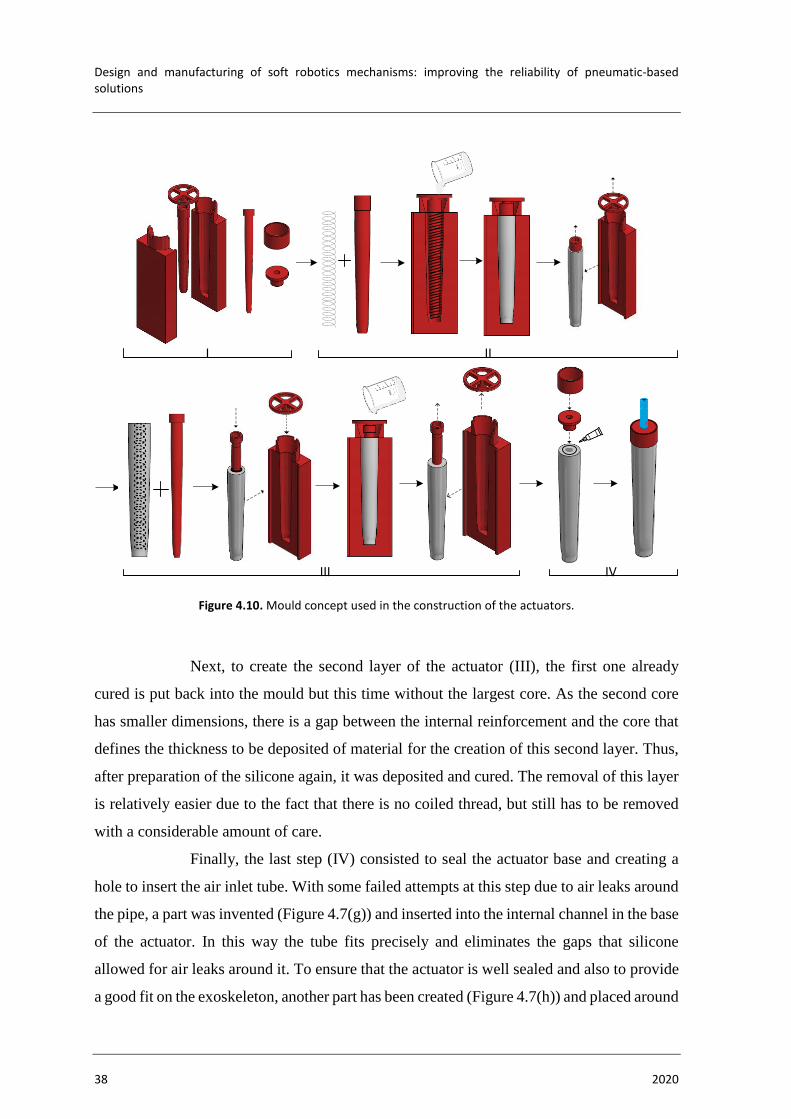
Design and manufacturing of soft robotics mechanisms: improving the reliability of pneumatic-based solutions
38 2020
Figure 4.10. Mould concept used in the construction of the actuators.
Next, to create the second layer of the actuator (III), the first one already
cured is put back into the mould but this time without the largest core. As the second core
has smaller dimensions, there is a gap between the internal reinforcement and the core that
defines the thickness to be deposited of material for the creation of this second layer. Thus,
after preparation of the silicone again, it was deposited and cured. The removal of this layer
is relatively easier due to the fact that there is no coiled thread, but still has to be removed
with a considerable amount of care.
Finally, the last step (IV) consisted to seal the actuator base and creating a
hole to insert the air inlet tube. With some failed attempts at this step due to air leaks around
the pipe, a part was invented (Figure 4.7(g)) and inserted into the internal channel in the base
of the actuator. In this way the tube fits precisely and eliminates the gaps that silicone
allowed for air leaks around it. To ensure that the actuator is well sealed and also to provide
a good fit on the exoskeleton, another part has been created (Figure 4.7(h)) and placed around
I II
III IV

DESIGN AND IMPLEMENTATION
Samuel José dos Reis Alves 39
the previous part. Both parts were glued with super glue Loctite 401 that exhibit a high curing
speed.
Figure 4.11. Fibre-reinforced index actuator.
4.2.3. Testing and Results
The results presented in this section only focus on hand manufacturing since the
pneumatic control system has not yet developed. However, in the following chapter, the
index finger has been pressurized manually with the aid of a pressure sensor (MPX4250AP)
programmed in Arduino, where it is possible to observe the motions of the index finger when
subjected to different pressure values.
Concerning the manufacture of the exoskeleton, 3D printing proved to be an
excellent option, presenting high quality and dimensional precision, where the finger area
exhibited the necessary flexibility to perform the folding. In the palm area, during the 3D
printing, it was necessary to create support material, therefore, some surface imperfections
were present when the support was removed. In addition, the thumb area on the palm became
more rigid than expected, and it was not possible for the two actuators mentioned in section
3.2 to perform the opposition/reposition movement. However, the latter problem described
was due to an exaggerated allocation of thickness in the CAD design and not because of the
printing. The hand 3D printing required about 30 hours to be concluded.
The actuators created have proven that their overall concept works well and that
they have the capabilities to actuate the exoskeleton. They can resist the necessary pressures,
where the concept of PET reinforcement has been validated, avoiding radial deformations
and favouring longitudinal deformations. However, the construction process has shown great
manual care, requiring some attempts to create actuators of acceptable quality. The reason
for this is due to the porosities (air bubbles) that occur during deposition and cure.
In the assembly (Figure 4.12), when the actuators were pressurized manually, it
was found that the concept described in section 3.2 works perfectly, where the motions of

Design and manufacturing of soft robotics mechanisms: improving the reliability of pneumatic-based solutions
40 2020
the fingers showed good bending motion, proving that 3D printing with flexible materials
has great potential.
Figure 4.12. Soft pneumatic hand. (a) Isometric view; (b) Front view.
(a) (b)
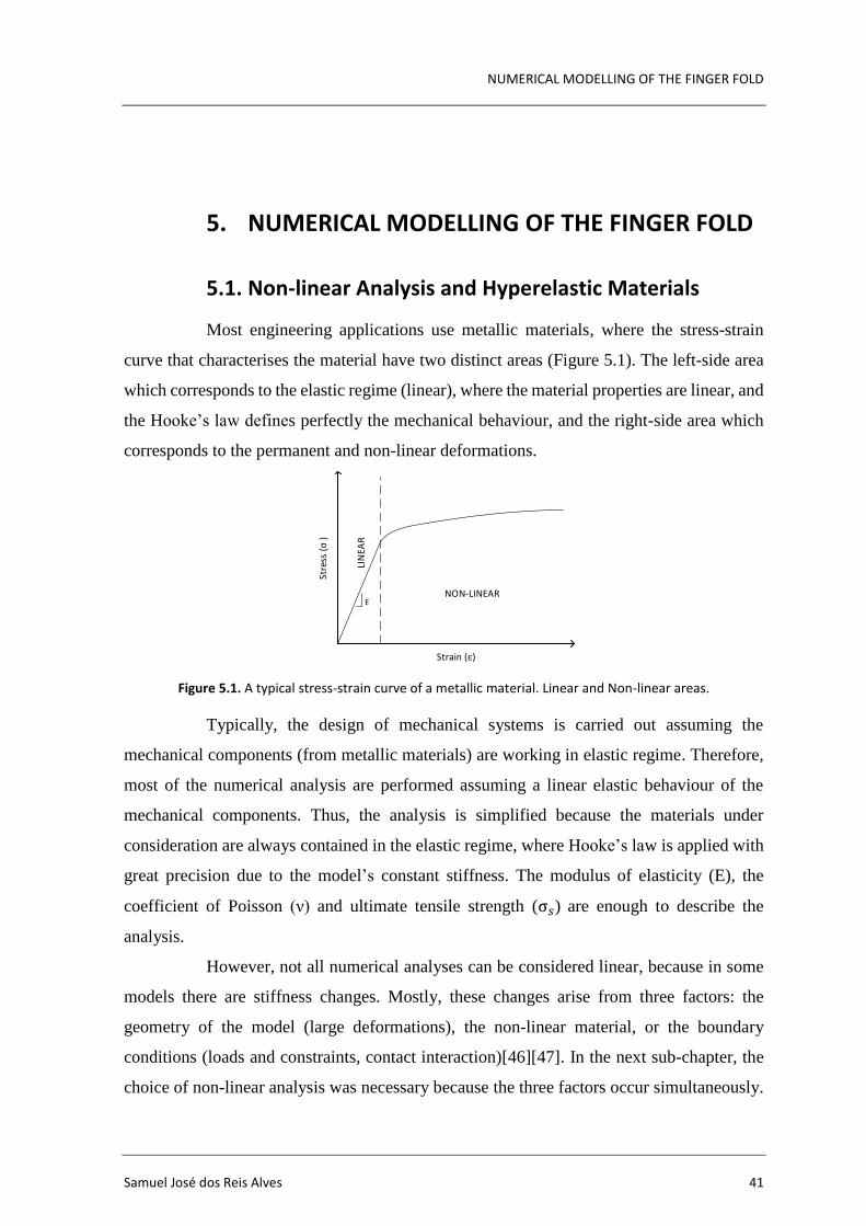
NUMERICAL MODELLING OF THE FINGER FOLD
Samuel José dos Reis Alves 41
5. NUMERICAL MODELLING OF THE FINGER FOLD
5.1. Non-linear Analysis and Hyperelastic Materials
Most engineering applications use metallic materials, where the stress-strain
curve that characterises the material have two distinct areas (Figure 5.1). The left-side area
which corresponds to the elastic regime (linear), where the material properties are linear, and
the Hooke’s law defines perfectly the mechanical behaviour, and the right-side area which
corresponds to the permanent and non-linear deformations.
Figure 5.1. A typical stress-strain curve of a metallic material. Linear and Non-linear areas.
Typically, the design of mechanical systems is carried out assuming the
mechanical components (from metallic materials) are working in elastic regime. Therefore,
most of the numerical analysis are performed assuming a linear elastic behaviour of the
mechanical components. Thus, the analysis is simplified because the materials under
consideration are always contained in the elastic regime, where Hooke’s law is applied with
great precision due to the model’s constant stiffness. The modulus of elasticity (E), the
coefficient of Poisson (ν) and ultimate tensile strength (σ𝑠) are enough to describe the
analysis.
However, not all numerical analyses can be considered linear, because in some
models there are stiffness changes. Mostly, these changes arise from three factors: the
geometry of the model (large deformations), the non-linear material, or the boundary
conditions (loads and constraints, contact interaction)[46][47]. In the next sub-chapter, the
choice of non-linear analysis was necessary because the three factors occur simultaneously.
LIN
EAR
NON-LINEARE
Strain (ε)
Stre
ss (σ
)
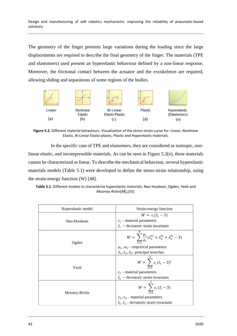
Design and manufacturing of soft robotics mechanisms: improving the reliability of pneumatic-based solutions
42 2020
The geometry of the finger presents large variations during the loading since the large
displacements are required to describe the final geometry of the finger. The materials (TPE
and elastomers) used present an hyperelastic behaviour defined by a non-linear response.
Moreover, the frictional contact between the actuator and the exoskeleton are required,
allowing sliding and separations of some regions of the bodies.
Figure 5.2. Different material behaviours. Visualization of the stress-strain curve for: Linear, Nonlinear Elastic, Bi-Linear Elasto-plastic, Plastic and Hyperelastic materials.
In the specific case of TPE and elastomers, they are considered as isotropic, non-
linear elastic, and incompressible materials. As can be seen in Figure 5.2(e), these materials
cannot be characterized as linear. To describe the mechanical behaviour, several hyperelastic
materials models (Table 5.1) were developed to define the stress-strain relationship, using
the strain-energy function (W) [48].
Table 5.1. Different models to characterize hyperelastic materials: Neo-Hookean, Ogden, Yeoh and Mooney-Rivlin[48],[33].
Hyperelastic model Strain-energy function
Neo-Hookean
𝑊 = 𝑐𝑖(𝐼1 − 3)
𝑐𝑖 – material parameters
𝐼1 − deviatoric strain invariants
Ogden
𝑊 = ∑µ𝑖
𝛼𝑖
𝑁
𝑖=1
(𝜆1𝛼𝑖 + 𝜆3
𝛼𝑖 + 𝜆3𝛼𝑖 − 3)
µ1 , 𝛼2 – emprirical parameters
𝜆1, 𝜆2, 𝜆3- principal stretches
Yeoh
𝑊 = ∑ 𝑐𝑖
3
𝑖=1
(𝐼1 − 3)𝑖
𝑐𝑖 – material parameters
𝐼1 − deviatoric strain invariants
Mooney-Rivlin
𝑊 = ∑ 𝑐𝑖
2
𝑖=1
(𝐼𝑖 − 3)
𝑐1 , 𝑐2 – material parameters
𝐼1 , 𝐼2 – deviatoric strain invariants

NUMERICAL MODELLING OF THE FINGER FOLD
Samuel José dos Reis Alves 43
In the study [49], uniaxial tensile tests were performed on three different
silicones (Ecoflex™ 00-30, Ecoflex™ 00-50 e Dragon Skin™ 30). The tests were executed
with 30mm-6mm-3mm samples on an Instron testing machine with a 100 N load cell at a
speed of 300mm/min of the transverse head. Then, the hyperelastic models were adjusted to
the experimental data in the strain range of 0-300%, where the use of least squares methods
allowed to obtain the best model for each material and the respective coefficients of the
deformation energy equations (Table 5.2).
Table 5.2. Parameter values of different hyperelastic models to characterize Ecoflex™ 00-30, Ecoflex™ 00-50 and Dragon Skin™ 30 materials [49].
Material Hyperelastic model Coefficients Parameter value
(MPa)
Ecoflex™ 00-30 Yeoh
N
𝐶10
𝐶20
𝐶30
3
5072
-331
-15
Ecoflex™ 00-50 Ogden
N
µ1
𝛼1
µ2
𝛼2
µ3
𝛼3
3
107.9× 10³
1.55
21.47
7.86
-87.1× 10³
-1.91
Dragon Skin™ 30 Yeoh
N
𝐶10
𝐶20
2
1190
23.028
Also, in the study [33], with the TPE Ninjaflex, uniaxial tensile tests were
performed following the ISO 37 standard, in which the samples were stretched using Instron
Universal Tester 3345. The material parameters involved in the models were adjusted to the
experimental data obtained in the strain range of 0-500% with the Abaqus software, where
the least square curve fit was once again applied to determine the coefficients for each model
(Table 5.3). To understand which was the best model to characterize the material, the author
determined the sum of square error for each one and concluded that the Ogden model was
the most suitable for Ninjaflex.

Design and manufacturing of soft robotics mechanisms: improving the reliability of pneumatic-based solutions
44 2020
Table 5.3. Parameter values of different hyperelastic models to characterize Ninjaflex material [33].
Hyperelastic model Coefficients Parameter value
(MPa)
Sum of square error
(sse)
Ogden
µ1
𝛼1
µ2
𝛼2
µ3
𝛼3
-30.921
0.508
10.342
1.375
26.791
-0.482
0.644
Mooney-Rivlin 𝐶10
𝐶01
0.677
1.621 45.280
Yeoh
𝐶10
𝐶20
𝐶30
1.653
0.0324
0.000486
159.481
In both studies only uniaxial tests were performed, so the models are only
adjusted to the stress-strain curves of these same tensile tests. However, it recommended
performing other experimental tests, such as biaxial tests, simple and pure shear tests.
5.2. Development of the Computational Model
The numerical analysis of the system was carried out using software Autodesk
Inventor Nastran®. The computational model was developed to simulate the capabilities of
the fibre-reinforced actuator when working in conjunction with Ninjaflex exoskeleton. The
creation of a model allows to predict several results and optimize geometries for better
performance without spending resources and saving time.
The entire computational model detailed below only pertains to the index
finger since it would be the same principle for the other fingers. The design of the hand
exoskeleton consists of only one CAD file, but due to the high detail, the simulations was
slower, and there was more chance to suffer convergence problems. Since the study only
focuses on the index finger, to simplify, the hand exoskeleton CAD has been cut off, creating
a solid of the index finger (Figure 5.3).

NUMERICAL MODELLING OF THE FINGER FOLD
Samuel José dos Reis Alves 45
Figure 5.3. Simplification of the model. (a) Hand design with visualization of the plans to cut off the finger - CAD file; (b) Index finger exoskeleton - CAD file.
The main goal of the FEA was to predict the mechanical behaviour of the
index finger, namely the maximum vertical displacement and the maximum finger folding
angle. These two types of results have been designated as the most relevant because the
primary function of a hand is to bend the fingers to achieve excellent manipulation and
dexterity characteristics. Nevertheless, before running this numerical model, it was
necessary to ensure the best numerical characterization of the materials. Therefore, two types
of simulations combined with experimental tests were previously performed. The goal was
to analyse the accuracy of the parameters obtained in the literature review, and if necessary,
change them to bring them closer to reality. In addition, these simulations helped to predict
the behaviour of the actuator and the exoskeleton individually, when subjected to different
loads. The two types of simulation are divided into the hand exoskeleton (Ninjaflex) and the
actuator (Ecoflex™ 00-50 with PET) which are described below in detail.
5.2.1. Exoskeleton
To verify the coherence of the materials model parameters previously
obtained, numerical simulations and experimental tests were performed with different forces
applied to the fingertip of the exoskeleton. The comparison between numerical simulations
and experimental tests allowed to observe the difference in the characterization of the
material and use the necessary adjustments. In both cases, the maximum vertical
displacements for each force were annotated. The value of the forces corresponds to the
finger's own weight and weights of 7 g, 16 g, 28 g, 41 g and 57 g suspended by a thread.
(a) (b)
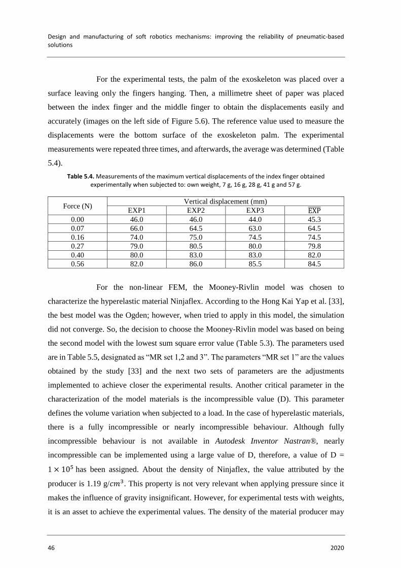
Design and manufacturing of soft robotics mechanisms: improving the reliability of pneumatic-based solutions
46 2020
For the experimental tests, the palm of the exoskeleton was placed over a
surface leaving only the fingers hanging. Then, a millimetre sheet of paper was placed
between the index finger and the middle finger to obtain the displacements easily and
accurately (images on the left side of Figure 5.6). The reference value used to measure the
displacements were the bottom surface of the exoskeleton palm. The experimental
measurements were repeated three times, and afterwards, the average was determined (Table
5.4).
Table 5.4. Measurements of the maximum vertical displacements of the index finger obtained experimentally when subjected to: own weight, 7 g, 16 g, 28 g, 41 g and 57 g.
Force (N) Vertical displacement (mm)
EXP1 EXP2 EXP3 EXP̅̅ ̅̅ ̅
0.00 46.0 46.0 44.0 45.3
0.07 66.0 64.5 63.0 64.5
0.16 74.0 75.0 74.5 74.5
0.27 79.0 80.5 80.0 79.8
0.40 80.0 83.0 83.0 82.0
0.56 82.0 86.0 85.5 84.5
For the non-linear FEM, the Mooney-Rivlin model was chosen to
characterize the hyperelastic material Ninjaflex. According to the Hong Kai Yap et al. [33],
the best model was the Ogden; however, when tried to apply in this model, the simulation
did not converge. So, the decision to choose the Mooney-Rivlin model was based on being
the second model with the lowest sum square error value (Table 5.3). The parameters used
are in Table 5.5, designated as “MR set 1,2 and 3”. The parameters “MR set 1” are the values
obtained by the study [33] and the next two sets of parameters are the adjustments
implemented to achieve closer the experimental results. Another critical parameter in the
characterization of the model materials is the incompressible value (D). This parameter
defines the volume variation when subjected to a load. In the case of hyperelastic materials,
there is a fully incompressible or nearly incompressible behaviour. Although fully
incompressible behaviour is not available in Autodesk Inventor Nastran®, nearly
incompressible can be implemented using a large value of D, therefore, a value of D =
1 × 10⁵ has been assigned. About the density of Ninjaflex, the value attributed by the
producer is 1.19 g/𝑐𝑚3. This property is not very relevant when applying pressure since it
makes the influence of gravity insignificant. However, for experimental tests with weights,
it is an asset to achieve the experimental values. The density of the material producer may

NUMERICAL MODELLING OF THE FINGER FOLD
Samuel José dos Reis Alves 47
be different from the real one because the 3D printing can change the original mechanical
properties. So, the calculation of the new density after the 3D printing was made. The 3D
printed exoskeleton was weighed, and the total volume was obtained from the CAD file,
𝜌 =𝑚𝑒𝑥𝑜𝑠𝑞𝑢𝑒𝑙𝑒𝑡𝑜𝑛
𝑉𝐶𝐴𝐷=
92 𝑔
111,209 𝑐𝑚3 = 0.827 𝑔/𝑐𝑚3, (5.1)
where ρ is the density, m is the weight and V is the volume. The real density is lower than
that given by the producer.
Table 5.5. Set of parameters of the Ninjaflex Mooney-Rivlin model. MR set 1 – Taken from the article [33].
MR Set 2 and 3 – Implemented adjustments.
𝐶10[MPa] 𝐶01[MPa]
MR set 1 0.677 1.621
MR set 2 0.300 0.750
MR set 3 0.210 0.525
For the modelling of the index finger exoskeleton was used parabolic solid
elements with a mesh size of 2.5 mm and a fixed constraint was applied on the surface
corresponding to the base of the hand (Figure 5.4). The simulation was repeated six times
(six forces) for each set of parameters, and then the values were compared with the average
experimental tests.
Figure 5.4. Modelling of index finger exoskeleton in Autodesk Inventor Nastran®. Fixed constraint, applied force and gravity.
The analysis of Figure 5.5 allows to conclude that using the “MR set 1”
parameters, the predicted vertical displacement is lower than the experimental one. This
means that the stiffness of the finger modelled with this set of parameters is larger than the
stiffness measured experimentally. So, the value of the parameters was decreased (“MR set
2”) in order to reduce the stiffness of the finger in the numerical model. Using the new set
of material parameters (“MR set 2”) in the numerical simulations allows to conclude that the
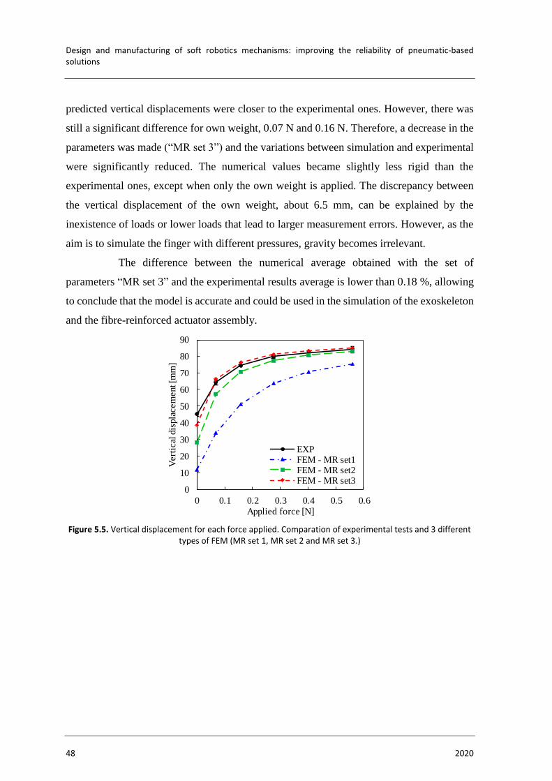
Design and manufacturing of soft robotics mechanisms: improving the reliability of pneumatic-based solutions
48 2020
predicted vertical displacements were closer to the experimental ones. However, there was
still a significant difference for own weight, 0.07 N and 0.16 N. Therefore, a decrease in the
parameters was made (“MR set 3”) and the variations between simulation and experimental
were significantly reduced. The numerical values became slightly less rigid than the
experimental ones, except when only the own weight is applied. The discrepancy between
the vertical displacement of the own weight, about 6.5 mm, can be explained by the
inexistence of loads or lower loads that lead to larger measurement errors. However, as the
aim is to simulate the finger with different pressures, gravity becomes irrelevant.
The difference between the numerical average obtained with the set of
parameters “MR set 3” and the experimental results average is lower than 0.18 %, allowing
to conclude that the model is accurate and could be used in the simulation of the exoskeleton
and the fibre-reinforced actuator assembly.
Figure 5.5. Vertical displacement for each force applied. Comparation of experimental tests and 3 different types of FEM (MR set 1, MR set 2 and MR set 3.)
0
10
20
30
40
50
60
70
80
90
0 0.1 0.2 0.3 0.4 0.5 0.6
Vert
ical
dis
pla
cem
ent [m
m]
Applied force [N]
EXPFEM - MR set1FEM - MR set2FEM - MR set3
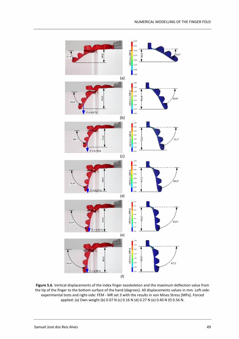
NUMERICAL MODELLING OF THE FINGER FOLD
Samuel José dos Reis Alves 49
Figure 5.6. Vertical displacements of the index finger exoskeleton and the maximum deflection value from the tip of the finger to the bottom surface of the hand (degrees). All displacements values in mm. Left-side:
experimental tests and right-side: FEM - MR set 3 with the results in von Mises Stress [MPa]. Forced applied: (a) Own weight (b) 0.07 N (c) 0.16 N (d) 0.27 N (e) 0.40 N (f) 0.56 N.
(a)
(b)
(c)
(d)
(e)
(f)

Design and manufacturing of soft robotics mechanisms: improving the reliability of pneumatic-based solutions
50 2020
5.2.2. Fibre-Reinforced Actuator
As mentioned in section 3.2, the actuator is composed of Ecoflex™ 00-50 and a
PET reinforcement, that consists of a high stiffness material with a very high modulus of
elasticity and due to its winding shape, the actuator does not exhibit radial deformations,
providing only longitudinal deformation, which consequently increases the length of the
actuator. To explain the relevance of the reinforcement, a numerical simulation of an actuator
without reinforcement was created in order to help the reader to interpret its function (Figure
5.7(a)). It can be observed that when the reinforcement is not used, the actuator tends to
deform radially creating a balloon shape. On the other hand, the inclusion of the PET
reinforcement, leads to an increase of the actuator length as the interior pressure increases
(Figure 5.7(b)).
Figure 5.7. Pressurized actuator modelling without reinforcement (a) and with reinforcement (b). Both models pressurized with 30 kPa. Von Mises Strain results.
In order to assess the accuracy of the material parameters used in [49] for the
mechanical characterization of the Ecoflex™ 00-50 with the Ogden model, the numerical
results of the actuator (without being inserted in the exoskeleton) are compared with the
experimental ones. The objective was to obtain the increase of length (maximum value of
horizontal displacement) for different pressures and compare the range of discrepancy
between them and apply the necessary adjustments to the parameters that describe the model.
The experimental tests were performed for pressures of 20, 40, 50 and 60 kPa.
To provide better visualization of the horizontal displacement and to obtain a better precision
of the results, a millimetre sheet of paper was placed under the actuator, and a part was
created in the 3D printer to fix the actuator base (zone where the actuator fits into the
exoskeleton) to guarantee always the same initial reference of the actuator (Figure 5.12). The
part was fixed with two screws to a wooden board placed under the sheet of paper. Similarly,
vM
Str
ain
vM S
trai
n
(a) (b)
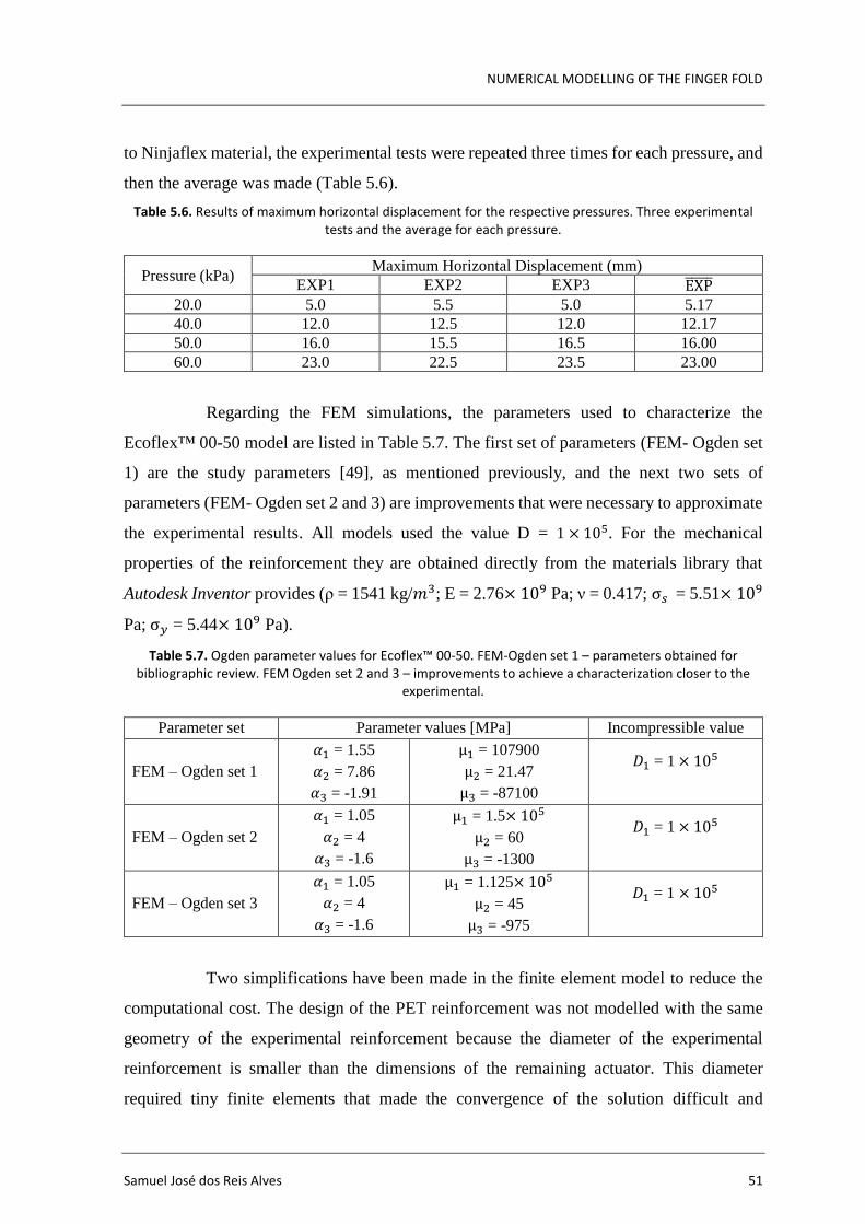
NUMERICAL MODELLING OF THE FINGER FOLD
Samuel José dos Reis Alves 51
to Ninjaflex material, the experimental tests were repeated three times for each pressure, and
then the average was made (Table 5.6).
Table 5.6. Results of maximum horizontal displacement for the respective pressures. Three experimental tests and the average for each pressure.
Pressure (kPa) Maximum Horizontal Displacement (mm)
EXP1 EXP2 EXP3 EXP̅̅ ̅̅ ̅
20.0 5.0 5.5 5.0 5.17
40.0 12.0 12.5 12.0 12.17
50.0 16.0 15.5 16.5 16.00
60.0 23.0 22.5 23.5 23.00
Regarding the FEM simulations, the parameters used to characterize the
Ecoflex™ 00-50 model are listed in Table 5.7. The first set of parameters (FEM- Ogden set
1) are the study parameters [49], as mentioned previously, and the next two sets of
parameters (FEM- Ogden set 2 and 3) are improvements that were necessary to approximate
the experimental results. All models used the value D = 1 × 10⁵. For the mechanical
properties of the reinforcement they are obtained directly from the materials library that
Autodesk Inventor provides (ρ = 1541 kg/𝑚3; E = 2.76× 10⁹ Pa; ν = 0.417; σ𝑠 = 5.51× 10⁹
Pa; σ𝑦 = 5.44× 10⁹ Pa).
Table 5.7. Ogden parameter values for Ecoflex™ 00-50. FEM-Ogden set 1 – parameters obtained for bibliographic review. FEM Ogden set 2 and 3 – improvements to achieve a characterization closer to the
experimental.
Parameter set Parameter values [MPa] Incompressible value
FEM – Ogden set 1
𝛼1 = 1.55
𝛼2 = 7.86
𝛼3 = -1.91
µ1 = 107900
µ2 = 21.47
µ3 = -87100
𝐷1 = 1 × 10⁵
FEM – Ogden set 2
𝛼1 = 1.05
𝛼2 = 4
𝛼3 = -1.6
µ1 = 1.5× 10⁵
µ2 = 60
µ3 = -1300
𝐷1 = 1 × 10⁵
FEM – Ogden set 3
𝛼1 = 1.05
𝛼2 = 4
𝛼3 = -1.6
µ1 = 1.125× 10⁵
µ2 = 45
µ3 = -975
𝐷1 = 1 × 10⁵
Two simplifications have been made in the finite element model to reduce the
computational cost. The design of the PET reinforcement was not modelled with the same
geometry of the experimental reinforcement because the diameter of the experimental
reinforcement is smaller than the dimensions of the remaining actuator. This diameter
required tiny finite elements that made the convergence of the solution difficult and
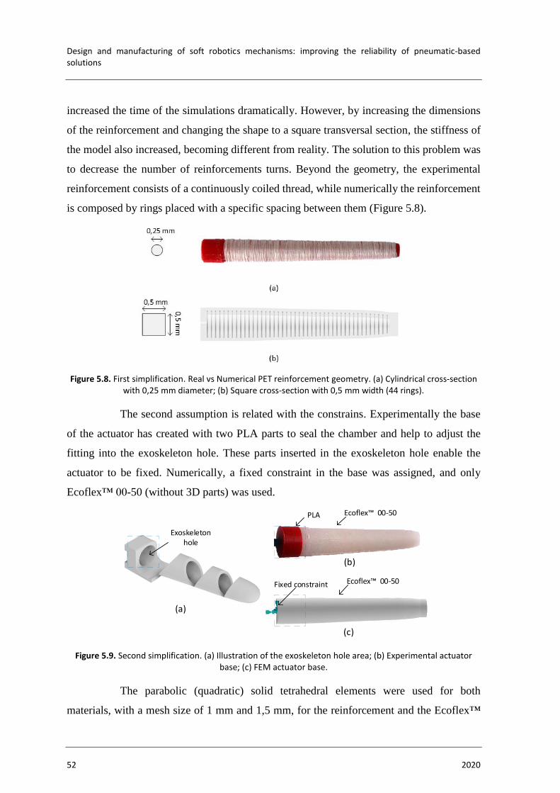
Design and manufacturing of soft robotics mechanisms: improving the reliability of pneumatic-based solutions
52 2020
increased the time of the simulations dramatically. However, by increasing the dimensions
of the reinforcement and changing the shape to a square transversal section, the stiffness of
the model also increased, becoming different from reality. The solution to this problem was
to decrease the number of reinforcements turns. Beyond the geometry, the experimental
reinforcement consists of a continuously coiled thread, while numerically the reinforcement
is composed by rings placed with a specific spacing between them (Figure 5.8).
Figure 5.8. First simplification. Real vs Numerical PET reinforcement geometry. (a) Cylindrical cross-section with 0,25 mm diameter; (b) Square cross-section with 0,5 mm width (44 rings).
The second assumption is related with the constrains. Experimentally the base
of the actuator has created with two PLA parts to seal the chamber and help to adjust the
fitting into the exoskeleton hole. These parts inserted in the exoskeleton hole enable the
actuator to be fixed. Numerically, a fixed constraint in the base was assigned, and only
Ecoflex™ 00-50 (without 3D parts) was used.
Figure 5.9. Second simplification. (a) Illustration of the exoskeleton hole area; (b) Experimental actuator base; (c) FEM actuator base.
The parabolic (quadratic) solid tetrahedral elements were used for both
materials, with a mesh size of 1 mm and 1,5 mm, for the reinforcement and the Ecoflex™
Ecoflex 00- 0PLA
Ecoflex 00- 0Fixed constraint
Exoskeleton hole
(a)
(b)
(c)
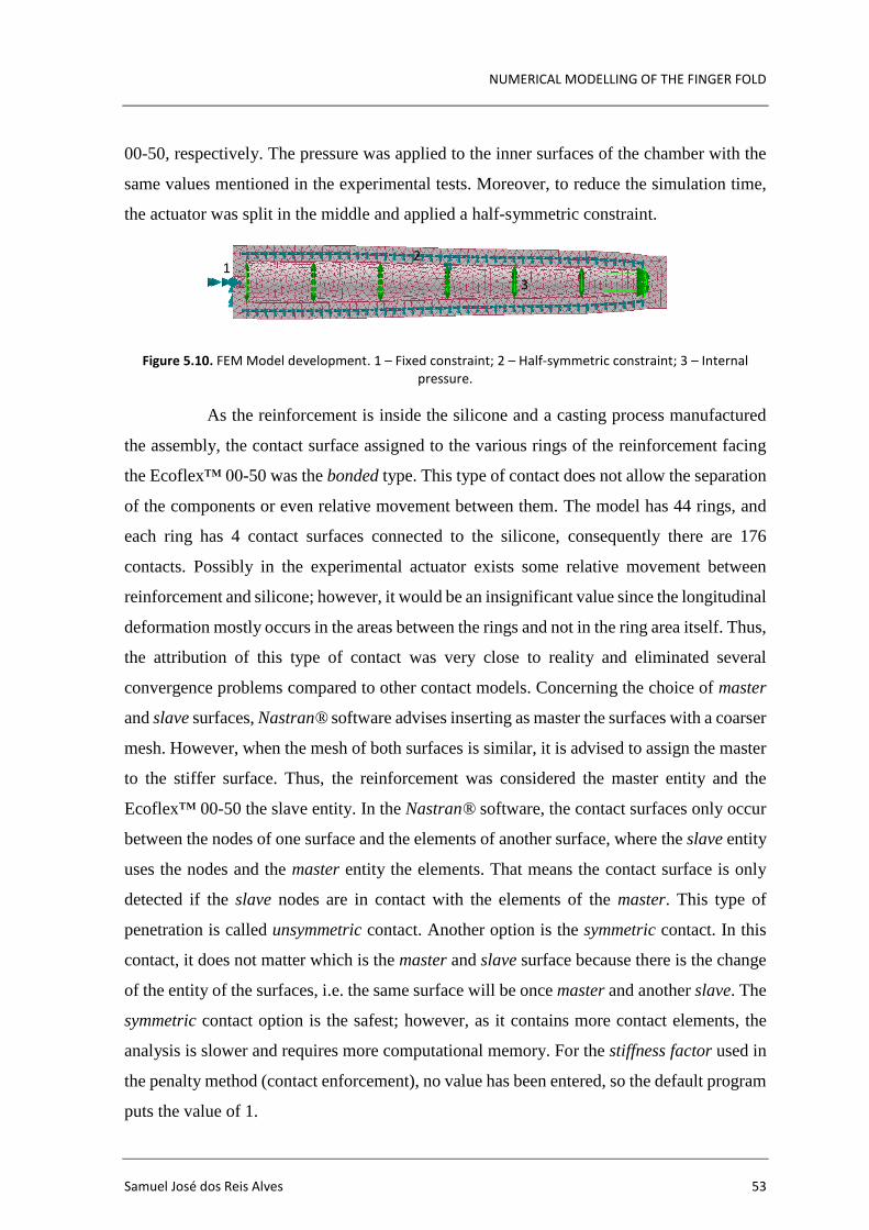
NUMERICAL MODELLING OF THE FINGER FOLD
Samuel José dos Reis Alves 53
00-50, respectively. The pressure was applied to the inner surfaces of the chamber with the
same values mentioned in the experimental tests. Moreover, to reduce the simulation time,
the actuator was split in the middle and applied a half-symmetric constraint.
Figure 5.10. FEM Model development. 1 – Fixed constraint; 2 – Half-symmetric constraint; 3 – Internal pressure.
As the reinforcement is inside the silicone and a casting process manufactured
the assembly, the contact surface assigned to the various rings of the reinforcement facing
the Ecoflex™ 00-50 was the bonded type. This type of contact does not allow the separation
of the components or even relative movement between them. The model has 44 rings, and
each ring has 4 contact surfaces connected to the silicone, consequently there are 176
contacts. Possibly in the experimental actuator exists some relative movement between
reinforcement and silicone; however, it would be an insignificant value since the longitudinal
deformation mostly occurs in the areas between the rings and not in the ring area itself. Thus,
the attribution of this type of contact was very close to reality and eliminated several
convergence problems compared to other contact models. Concerning the choice of master
and slave surfaces, Nastran® software advises inserting as master the surfaces with a coarser
mesh. However, when the mesh of both surfaces is similar, it is advised to assign the master
to the stiffer surface. Thus, the reinforcement was considered the master entity and the
Ecoflex™ 00-50 the slave entity. In the Nastran® software, the contact surfaces only occur
between the nodes of one surface and the elements of another surface, where the slave entity
uses the nodes and the master entity the elements. That means the contact surface is only
detected if the slave nodes are in contact with the elements of the master. This type of
penetration is called unsymmetric contact. Another option is the symmetric contact. In this
contact, it does not matter which is the master and slave surface because there is the change
of the entity of the surfaces, i.e. the same surface will be once master and another slave. The
symmetric contact option is the safest; however, as it contains more contact elements, the
analysis is slower and requires more computational memory. For the stiffness factor used in
the penalty method (contact enforcement), no value has been entered, so the default program
puts the value of 1.
12
3

Design and manufacturing of soft robotics mechanisms: improving the reliability of pneumatic-based solutions
54 2020
For each set of Ecoflex™ 00-50 parameters, the simulation was repeated four
times (20, 40, 50 and 60 kPa), and the results were inserted in Figure 5.11. For the first set
of parameters (FEM – Ogden set 1), the predicted maximum horizontal displacements were
considerably lower than the results obtained experimentally, meaning that the
characterization of the material numerically provides more rigidity. One of the reasons for
this difference lies not in using the vacuum chamber when manufacturing the actuator,
allowing the external environment to create air bubbles in the silicone, reducing its stiffness.
To approximate the experimental results, the parameters were decreased slightly (FEM –
Ogden set 2) in order to lower the stress-strain curve. The simulations were again performed,
and it was concluded that the stiffness of the material numerically was still higher, being
necessary to lower the parameters again (FEM – Ogden set 3). After new simulations, it was
possible to conclude that this last set of parameters presents horizontal displacement values
close to the experimental one, with an error of less than 10 % up to 50 kPa, determining
these parameters acceptable. For the value of 60 kPa, a significant discrepancy (17.6 %) is
noted that can be explained by the experimental result beginning to show some folding due
to the complexity of placing the symmetrical reinforcement manually (Figure 5.12(d)).
Figure 5.11. Horizontal displacement for each force applied. Comparation of experimental tests and 3 different types of FEM (Ogden set 1, Ogden set 2 and Ogden set 3).
0
5
10
15
20
25
20 30 40 50 60
Ho
rizo
nta
l dis
pla
cem
ent [m
m]
Pressure [kPa]
EXP
FEM - Ogden set1
FEM - Ogden set2
FEM - Ogden set3
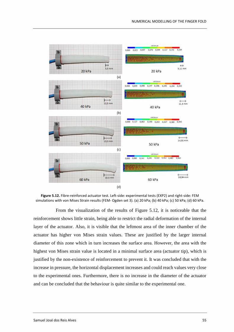
NUMERICAL MODELLING OF THE FINGER FOLD
Samuel José dos Reis Alves 55
Figure 5.12. Fibre-reinforced actuator test. Left-side: experimental tests (EXP2) and right-side: FEM simulations with von Mises Strain results (FEM- Ogden set 3). (a) 20 kPa; (b) 40 kPa; (c) 50 kPa; (d) 60 kPa.
From the visualization of the results of Figure 5.12, it is noticeable that the
reinforcement shows little strain, being able to restrict the radial deformation of the internal
layer of the actuator. Also, it is visible that the leftmost area of the inner chamber of the
actuator has higher von Mises strain values. These are justified by the larger internal
diameter of this zone which in turn increases the surface area. However, the area with the
highest von Mises strain value is located in a minimal surface area (actuator tip), which is
justified by the non-existence of reinforcement to prevent it. It was concluded that with the
increase in pressure, the horizontal displacement increases and could reach values very close
to the experimental ones. Furthermore, there is no increase in the diameter of the actuator
and can be concluded that the behaviour is quite similar to the experimental one.
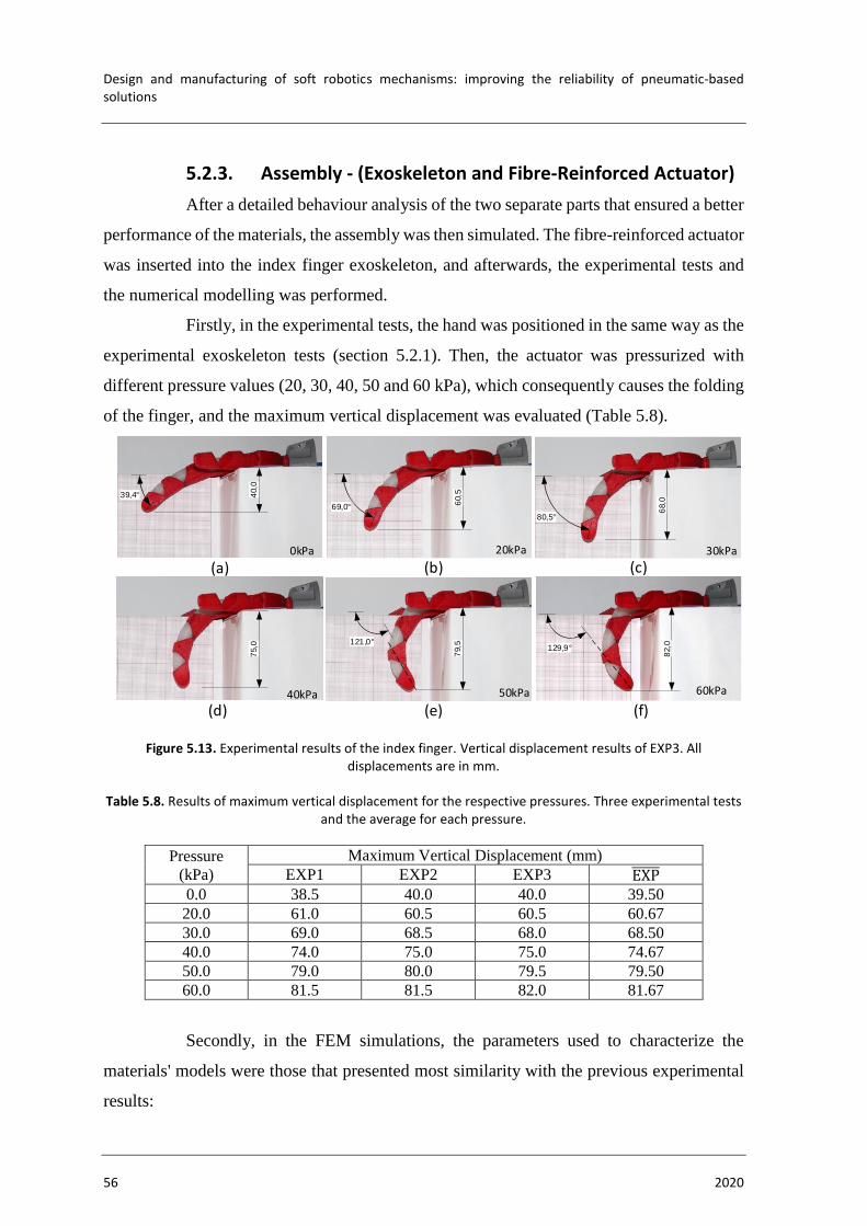
Design and manufacturing of soft robotics mechanisms: improving the reliability of pneumatic-based solutions
56 2020
5.2.3. Assembly - (Exoskeleton and Fibre-Reinforced Actuator)
After a detailed behaviour analysis of the two separate parts that ensured a better
performance of the materials, the assembly was then simulated. The fibre-reinforced actuator
was inserted into the index finger exoskeleton, and afterwards, the experimental tests and
the numerical modelling was performed.
Firstly, in the experimental tests, the hand was positioned in the same way as the
experimental exoskeleton tests (section 5.2.1). Then, the actuator was pressurized with
different pressure values (20, 30, 40, 50 and 60 kPa), which consequently causes the folding
of the finger, and the maximum vertical displacement was evaluated (Table 5.8).
Figure 5.13. Experimental results of the index finger. Vertical displacement results of EXP3. All displacements are in mm.
Table 5.8. Results of maximum vertical displacement for the respective pressures. Three experimental tests and the average for each pressure.
Pressure
(kPa)
Maximum Vertical Displacement (mm)
EXP1 EXP2 EXP3 EXP̅̅ ̅̅ ̅
0.0 38.5 40.0 40.0 39.50
20.0 61.0 60.5 60.5 60.67
30.0 69.0 68.5 68.0 68.50
40.0 74.0 75.0 75.0 74.67
50.0 79.0 80.0 79.5 79.50
60.0 81.5 81.5 82.0 81.67
Secondly, in the FEM simulations, the parameters used to characterize the
materials' models were those that presented most similarity with the previous experimental
results:
82,0129,9°
79,5
75,0
68,0
80,5°
60,5
69,0°
20kPa 30kPa
40kPa 50kPa
121,0°
60kPa
(a) (b)
(d) (e)
(c)
(f)
40,0
39,4°
0kPa

NUMERICAL MODELLING OF THE FINGER FOLD
Samuel José dos Reis Alves 57
• Ninjaflex – FEM MR set 3;
• Ecoflex™ 00-50 – FEM Ogden set 3;
• PET reinforcement – Autodesk Inventor Nastran® properties;
The mesh size of the reinforcement and the actuator was the same used in the
last model with 1mm and 1,5 mm, respectively. For the exoskeleton, the mesh size was
decreased to 1,5 mm to enhance the performance of the model convergence. All of them are
modelled as parabolic solid elements. A fixed constraint was applied in the base of the
exoskeleton, and just like the fibre-reinforced actuator model, the assembly was split in the
middle and was implemented a half-symmetric constraint. The pressure was again applied
on the inner surfaces of the actuator. The gravity was not applied to the model because the
hand could have been actuated in several asymmetric positions, creating a discrepancy where
a few positions where more favoured than others. Besides that, the own weight would be
practically insignificant compared to the internal pressures that the actuator is subject.
Figure 5.14. FEM model development. 1 – Fixed constraint; 2 – Ty constraint; 3 – Half-symmetric constraint; 4 – Internal pressure.
Concerning the contact surfaces assigned in the previous simulation between the
reinforcement and the actuator have been repeated for this new model, being added the
contact surfaces between actuator and exoskeleton. Ideally, the contact surfaces between
them should be separated in all contacts, but this type of contact presents much complexity,
increasing the time and the difficulty to converge. For this purpose, some simplifications
were created in order to try to find a solution very similar to reality and simultaneously to
reduce the simulation time and the convergence problems. In Figure 5.15 are visible the 10
contacts applied between the exoskeleton and the actuator. For contact number 1, the
sliding/no separation contact was chosen because although the actuator is inserted in the
exoskeleton and there is no separation, the actuator has the capacity to deform longitudinally
when subjected to pressure, needing to slide relative to the exoskeleton. Next, when the
pressure inserted in the actuator increases, there is experimentally a clear separation in the
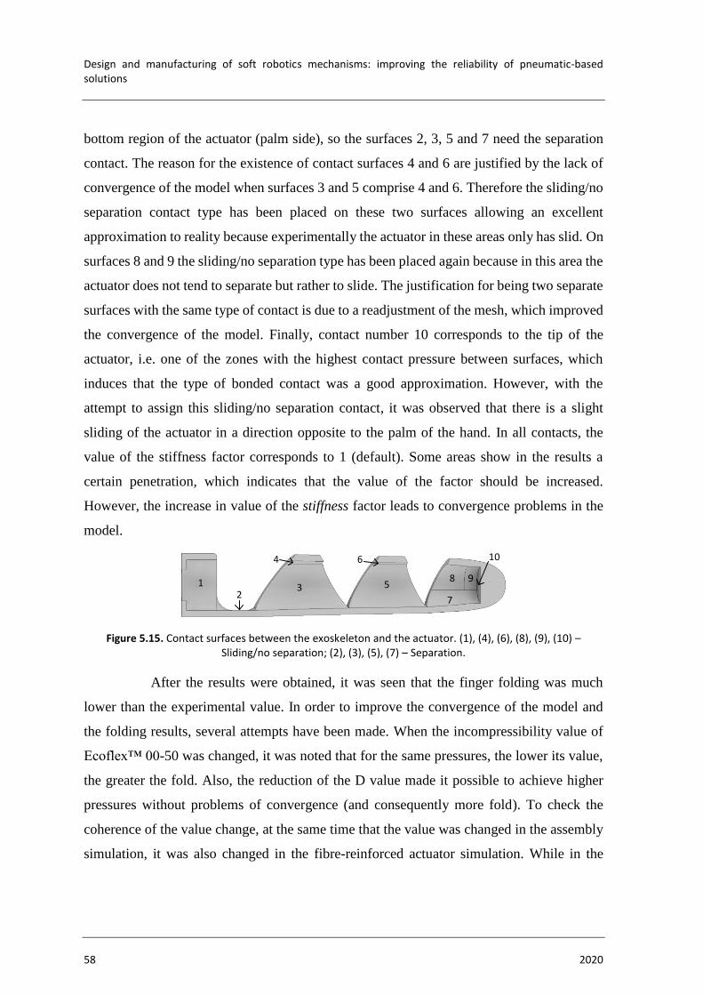
Design and manufacturing of soft robotics mechanisms: improving the reliability of pneumatic-based solutions
58 2020
bottom region of the actuator (palm side), so the surfaces 2, 3, 5 and 7 need the separation
contact. The reason for the existence of contact surfaces 4 and 6 are justified by the lack of
convergence of the model when surfaces 3 and 5 comprise 4 and 6. Therefore the sliding/no
separation contact type has been placed on these two surfaces allowing an excellent
approximation to reality because experimentally the actuator in these areas only has slid. On
surfaces 8 and 9 the sliding/no separation type has been placed again because in this area the
actuator does not tend to separate but rather to slide. The justification for being two separate
surfaces with the same type of contact is due to a readjustment of the mesh, which improved
the convergence of the model. Finally, contact number 10 corresponds to the tip of the
actuator, i.e. one of the zones with the highest contact pressure between surfaces, which
induces that the type of bonded contact was a good approximation. However, with the
attempt to assign this sliding/no separation contact, it was observed that there is a slight
sliding of the actuator in a direction opposite to the palm of the hand. In all contacts, the
value of the stiffness factor corresponds to 1 (default). Some areas show in the results a
certain penetration, which indicates that the value of the factor should be increased.
However, the increase in value of the stiffness factor leads to convergence problems in the
model.
Figure 5.15. Contact surfaces between the exoskeleton and the actuator. (1), (4), (6), (8), (9), (10) – Sliding/no separation; (2), (3), (5), (7) – Separation.
After the results were obtained, it was seen that the finger folding was much
lower than the experimental value. In order to improve the convergence of the model and
the folding results, several attempts have been made. When the incompressibility value of
Ecoflex™ 00-50 was changed, it was noted that for the same pressures, the lower its value,
the greater the fold. Also, the reduction of the D value made it possible to achieve higher
pressures without problems of convergence (and consequently more fold). To check the
coherence of the value change, at the same time that the value was changed in the assembly
simulation, it was also changed in the fibre-reinforced actuator simulation. While in the
1 3
4
8
72
9
10
5
6

NUMERICAL MODELLING OF THE FINGER FOLD
Samuel José dos Reis Alves 59
assembly, the simulation was closer to the real one, in the fibre-reinforced actuator
simulation, a very different deformation from the real one started to appear (Figure 5.16).
Figure 5.16. FEM simulation of a fibre-reinforced actuator with D=10. (20 kPa)
By noting this incongruence, it was concluded that since D controls the volume
variation of a material when subjected to a load, if the actuator is more constrained (on the
assembly), its effect is less visible. Thus, the value of D has been reduced from 1 × 10⁵ to
10. Based on the same approach, considering that the Poisson coefficient measures the
transverse deformation of isotropic material and considering that the reinforcement is
restricted by silicone, the value of the Poisson coefficient has been decreased from 0.417 to
0.17. A value below 0.17 would not be realistic.
Experimentally the finger reached its maximum folding angle at 100 kPa
(fingertip next to palm), but numerically, it was only possible to obtain results up to 47 kPa.
One possible reason for the model not being able to converge might be because a particular
increment changes the shape of the model significantly. However, the model was computed
with 200 and 300 increments, to decrease the value of the pressure in each increment, which
consequently, decreased the model shape, but in both cases, it did not improve the
convergence. The highest result was obtained with 100 increments.
vM S
trai
n

Design and manufacturing of soft robotics mechanisms: improving the reliability of pneumatic-based solutions
60 2020
Figure 5.17. FEM results of the assembly (Exoskeleton + Fibre-reinforced actuator). Visualization of von Mises Strain results, vertical displacement and folding angle. All displacement values are in mm.(a) 20 kPa;
(b) 30 kPa; (c) 40 kPa; (d) 47 kPa.
Figure 5.18. Vertical displacement for each pressure applied. Comparation between experimental tests and FEM simulations.
The numerical results show lower vertical displacement values compared to the
experimental ones, i.e. less bending for the same pressure. But it can be seen that with the
increase in pressure the numerical result tends to approach the experimental value. For the
pressure of 40 kPa there is a difference between the numerical and the experimental of
24.34%, which continues to decrease until the numerical convergence fails. Despite the
64
,61
47kPa
40kPa
56
,46
vM S
trai
n
21
,38
41
,78
20kPa
(a)
(b) (d)
(c)
30kPa
vM S
trai
nvM
Str
ain
vM S
trai
n
0
10
20
30
40
50
60
70
80
90
20.00 30.00 40.00 50.00
Vert
ical
dis
pla
cem
ent [m
m]
Pressure [kPa]
EXP
FEM

NUMERICAL MODELLING OF THE FINGER FOLD
Samuel José dos Reis Alves 61
results discrepancy, it is possible to visualize (Figure 5.17) that the finger folding behaviour
is similar to the experimental one (Figure 5.13), following the same evolution.
5.2.4. Finger Force Test
The maximum fingertip force is a relevant characteristic in the application of
object handling tasks, being one of the main direct relations with the weight of objects that
a finger can withstand. So, it was determined experimentally and numerically.
Experimentally, the determination of the force was realised with a balance
machine (TechMaster ES-3000A) (Figure 5.19(a)). A support was created that fixes the hand
in the horizontal at a vertical distance of 40 mm between the palm side and the balance. The
height has been chosen in order to assure that the finger has a bend lesser than 45 degrees so
that the force component can be mostly vertical. Moreover, at the same time the value should
be above zero degrees because this setting is not useful when handling objects. The index
finger is then pressurized (constant pressure increases), and when the fingertip starts to touch
the balance, it starts to register its mass. The value of the maximum mass displayed
multiplied by the acceleration of gravity corresponds to the maximum value of the finger's
pressure force.
Numerically, a duplicate of the assembly model (Section 5.2.3) was executed,
with a rigid body having been added with the respective distances described in the
experimental tests. The rigid body replaces the experimental balance. When the simulation
finished, the reaction force was obtained in the area of the constraint of the rigid body, which
indicates the value of the maximum force that the fingertip has applied to the rigid body. For
the value of the reaction force, it was necessary to multiply by two, because the finger model
was divided in half.
The values of the fingertip forces obtained experimentally and numerically have
been inserted in Figure 5.20. For the experimental tests, pressures from 20 to 80 kPa (with
an interval of 10 kPa) were applied. Numerically, the fingertip only reaches the surface at
33 kPa, so the results were obtained for pressures of 35, 40, 45 and 46.5 kPa. From the latter
value, the model once again failed to converge. The maximum fingertip force value
corresponds to 0.81 N for the maximum pressure reached of 80 kPa. While numerically, the
maximum force value corresponds to 0.176 N for the 47 kPa pressure. The numerical results
show some discrepancy with the experimental, but both exhibit the same trend. As pressure
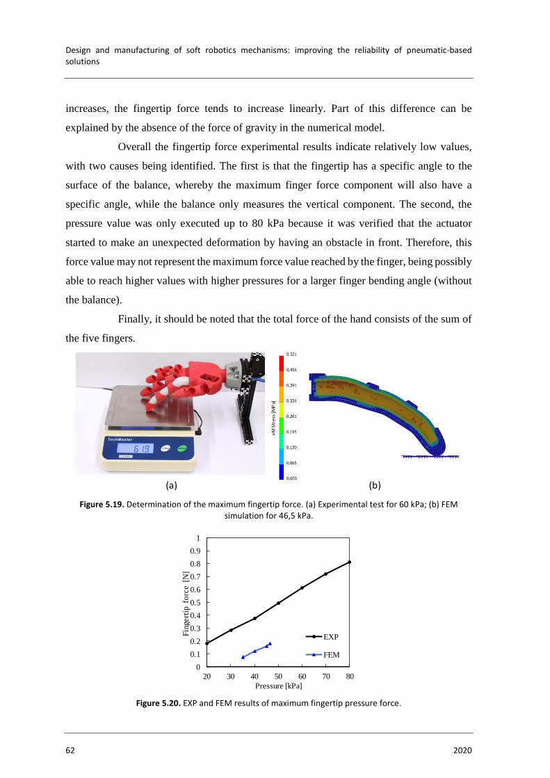
Design and manufacturing of soft robotics mechanisms: improving the reliability of pneumatic-based solutions
62 2020
increases, the fingertip force tends to increase linearly. Part of this difference can be
explained by the absence of the force of gravity in the numerical model.
Overall the fingertip force experimental results indicate relatively low values,
with two causes being identified. The first is that the fingertip has a specific angle to the
surface of the balance, whereby the maximum finger force component will also have a
specific angle, while the balance only measures the vertical component. The second, the
pressure value was only executed up to 80 kPa because it was verified that the actuator
started to make an unexpected deformation by having an obstacle in front. Therefore, this
force value may not represent the maximum force value reached by the finger, being possibly
able to reach higher values with higher pressures for a larger finger bending angle (without
the balance).
Finally, it should be noted that the total force of the hand consists of the sum of
the five fingers.
Figure 5.19. Determination of the maximum fingertip force. (a) Experimental test for 60 kPa; (b) FEM simulation for 46,5 kPa.
Figure 5.20. EXP and FEM results of maximum fingertip pressure force.
vM
Str
ess
[M
Pa]
(a) (b)
0
0.1
0.2
0.3
0.4
0.5
0.6
0.7
0.8
0.9
1
20 30 40 50 60 70 80
Fin
gert
ip f
orc
e [
N]
Pressure [kPa]
EXP
FEM

CONCLUSIONS
Samuel José dos Reis Alves 63
6. CONCLUSIONS
This dissertation describes the design and manufacture of a pneumatic robotic
hand prototype which is based on the robotics sub-area soft robotics. Soft materials were
used, i.e. materials with elastic, flexible and soft properties, which provides to the robotic
hand the ability of adaptation to the environment in a safe way and with the necessary
compliance to deal with delicate objects. The soft hand offers a human-like shape, with the
dimensions of an adult human hand.
The concept of the hand motion was based on the article of Jan Fras and Kaspar
Althoefer [3][30], where the hand was built by two different types of components, the
exoskeleton and the reinforced actuators. The first component was created from direct 3D
printing using a TPE called Ninjaflex. Overall the 3D printed material provided good quality
and precision to the robotic hand, except to the palm of the hand in the area where the two
actuators would be inserted to create the opposition/reposition movement. This zone became
more rigid than supposed, however, the problem was not directly related to the 3D printing,
but to the CAD design. For the actuators a manual deposition process was used, pin casting,
where the moulds and pins (cores) were created in 3D printing and the material cast in the
moulds consisted of the Ecoflex™ 00-50, an elastomer with excellent elongation properties,
elasticity and low hardness. These actuators also include a polyethylene terephthalate thread
as a reinforcement function to avoid radial deformations and favour longitudinal
deformations. In addition, to seal the actuators, two 3D printed PLA parts were created,
which were glued to the base of the actuator (inlet pressure area). The created actuators
showed good reliability and resistance for the required pressure range; however, the
construction process required a lot of manual care, being necessary to repeat them a few
times to achieve good results due to the porosity during deposition and cure. In the assembly,
when the actuators were pressurized, the finger motion demonstrated good bending motion.
Then, a numerical model was developed with Autodesk Inventor Nastran®
software in order to compare the folding behaviour of the index finger with the experimental
tests. The objective of the model elaboration was to try to approximate the numerical results
with the experimental ones, because once these are proved, it means that the model can

Design and manufacturing of soft robotics mechanisms: improving the reliability of pneumatic-based solutions
64 2020
perform the same concept for different geometries and optimizations. The Ninjaflex and
Ecoflex™ 00-50 are considered hyperelastic materials, their properties are obtained from the
literature. To ensure a good material characterization, it was decided to model the
components separately first, and compare the mechanical behaviour with the experimental
tests. For the exoskeleton, tests with suspended weights at the fingertip were executed, where
the vertical displacement was noted. For the reinforced actuators, tests of free horizontal
displacement with different inlet pressures were executed. In both cases, the numerical
characterization revealed stiffness values higher than the experimental results, so
adjustments in the parameters were performed to obtain acceptable values. After the
necessary adjustments, the assembly model was created. However, due to the geometry
complexity, and because the model contains three different materials, there were many
difficulties. It was possible to observe that the mechanical behaviour follows the same trend
line, but with the need for higher-pressure values to achieve the same experimental results.
Also, numerical results were not achieved after a value above 47 kPa. One of the reasons
that may justify the lack of convergence is due to a specific increment in the model that
strongly changes the bending behaviour of the finger.
Finally, a fingertip force test was also performed, because it is a very important
characteristic in the handling of objects. The hand was positioned at 40 mm vertical
displacement between the palm and the fingertip. Although the numerical results show
discrepancy with the experimental, both show the same trend with increasing pressure.
6.1. Future Work
Given the good results of the exoskeleton printed directly with a 3D printer with
a TPE material, direct manufacture of the actuators could also be an excellent choice. As
referred in state of the art, there are already works developed to 3D print silicones directly,
designated as DIW; however, it is a process that needs to make big changes in the 3D printer.
Recently, Recreus launched a new TPE (Filaflex 70A)[50], which is described as ultra-soft,
flexible and with 900% elongation. As the hardness of this material is less than the one
presented by Ninjaflex, it means that Ninjaflex is able to restrict actuator deformation at the
desired locations and perform good bending behaviour. Besides that, this material has higher

CONCLUSIONS
Samuel José dos Reis Alves 65
hardness than Ecoflex™ 00-50, the stiffness of the set increased, and the hand was able to
withstand higher forces.
Concerning manufacturing, since the palm of the hand presents excessive
stiffness in the thumb area limiting its opposition/reposition movement, a design
improvement will be created.
The hand will incorporate a high precision pneumatic control system, to execute
different grasping postures.
Regarding to numerical modelling, the problem of lack of convergence will be
studied again, and when solved, different variations of geometry will be performed to study
their influence on finger bending.

Design and manufacturing of soft robotics mechanisms: improving the reliability of pneumatic-based solutions
66 2020
BIBLIOGRAPHY
Samuel José dos Reis Alves 67
BIBLIOGRAPHY
[1] D. Trivedi, C. D. Rahn, W. M. Kier, and I. D. Walker, “Soft robotics: Biological
inspiration, state of the art, and future research,” Appl. Bionics Biomech., vol. 5,
no. 3, pp. 99–117, 2008, doi: 10.1080/11762320802557865.
[2] F. Putzu, J. Konstantinova, and K. Althoefer, “Soft Particles for Granular
Jamming,” pp. 65–74, 2019, doi: 10.1007/978-3-030-25332-5_6.
[3] J. Fras and K. Althoefer, “Soft Biomimetic Prosthetic Hand: Design,
Manufacturing and Preliminary Examination,” IEEE Int. Conf. Intell. Robot.
Syst., pp. 6998–7003, 2018, doi: 10.1109/IROS.2018.8593666.
[4] C. Laschi, M. Cianchetti, B. Mazzolai, L. Margheri, M. Follador, and P. Dario,
“Soft robot arm inspired by the octopus,” Adv. Robot., vol. 26, no. 7, pp. 709–
727, 2012, doi: 10.1163/156855312X626343.
[5] P. M. Matos, “Collaborative Gripper for Robotic Application.” Tese de Mestrado
em Engenharia Mecânica na especialidade de Produção e Projeto, Departamento
de Engenharia Mecânica, Faculdade de Ciências e Tecnologia, Universidade de
Coimbra, 2019.
[6] R. Deimel and O. Brock, “A Novel Type of Compliant, Underactuated Robotic
Hand for Dexterous Grasping,” 2015, doi: 10.15607/rss.2014.x.018.
[7] D. Rus and M. T. Tolley, “Design, fabrication and control of soft robots,”
Nature, vol. 521, no. 7553, pp. 467–475, 2015, doi: 10.1038/nature14543.
[8] C. P. Chou and B. Hannaford, “Measurement and modeling of McKibben
pneumatic artificial muscles,” IEEE Trans. Robot. Autom., vol. 12, no. 1, pp. 90–
102, 1996, doi: 10.1109/70.481753.
[9] A. D. Marchese, R. K. Katzschmann, and D. Rus, “A recipe for soft fluidic
elastomer robots,” Soft Robot., vol. 2, no. 1, pp. 7–25, 2015, doi:
10.1089/soro.2014.0022.
[10] B. Mosadegh et al., “Pneumatic networks for soft robotics that actuate rapidly,”
Adv. Funct. Mater., vol. 24, no. 15, pp. 2163–2170, 2014, doi:
10.1002/adfm.201303288.
[11] K. C. Galloway, P. Polygerinos, C. J. Walsh, and R. J. Wood, “Mechanically
Programmable Bend Radius for Fiber-Reinforced Soft Actuators,” Appl. Phys. B
Lasers Opt., vol. 105, no. 4, 2011, doi: 10.1109/ICAR.2013.6766586.
[12] H. Wang et al., “Fiber-reinforced soft robotic anthropomorphic finger,” 2016 Int.
Conf. Robot. Autom. Eng. ICRAE 2016, pp. 1–5, 2016, doi:
10.1109/ICRAE.2016.7738777.
[13] J. Fras and K. Althoefer, “Soft Fiber-Reinforced Pneumatic Actuator Design and

Design and manufacturing of soft robotics mechanisms: improving the reliability of pneumatic-based solutions
68 2020
Fabrication: Towards Robust, Soft Robotic Systems,” Lect. Notes Comput. Sci.
(including Subser. Lect. Notes Artif. Intell. Lect. Notes Bioinformatics), vol.
11649 LNAI, pp. 103–114, 2019, doi: 10.1007/978-3-030-23807-0_9.
[14] Y. Li, Y. Chen, Y. Yang, and Y. Wei, “Passive Particle Jamming and Its
Stiffening of Soft Robotic Grippers,” IEEE Trans. Robot., vol. 33, no. 2, pp.
446–455, 2017.
[15] Y. Li, Y. Chen, and Y. Li, “Distributed design of passive particle jamming based
soft grippers,” 2018 IEEE Int. Conf. Soft Robot. RoboSoft 2018, pp. 547–552,
2018, doi: 10.1109/ROBOSOFT.2018.8405383.
[16] M. Elkeran and M. Fanni, “A transient FEA-based methodology for designing
soft surgical manipulators,” in Proceedings of 2018 IEEE International
Conference on Mechatronics and Automation, ICMA 2018, 2018, pp. 568–573,
doi: 10.1109/ICMA.2018.8484508.
[17] M. Cianchetti, T. Ranzani, G. Gerboni, I. De Falco, C. Laschi, and A. Menciassi,
“STIFF-FLOP surgical manipulator: Mechanical design and experimental
characterization of the single module,” IEEE Int. Conf. Intell. Robot. Syst., no.
August, pp. 3576–3581, 2013, doi: 10.1109/IROS.2013.6696866.
[18] M. Cianchetti et al., “Soft Robotics Technologies to Address Shortcomings in
Today’s Minimally Invasive Surgery: The STIFF-FLOP Approach,” Soft Robot.,
vol. 1, no. 2, pp. 122–131, 2014, doi: 10.1089/soro.2014.0001.
[19] Z. Wang and S. Hirai, “A 3D printed soft gripper integrated with curvature
sensor for studying soft grasping,” SII 2016 - 2016 IEEE/SICE Int. Symp. Syst.
Integr., pp. 629–633, 2017, doi: 10.1109/SII.2016.7844069.
[20] Z. Wang, D. S. Chathuranga, and S. Hirai, “3D printed soft gripper for automatic
lunch box packing,” 2016 IEEE Int. Conf. Robot. Biomimetics, ROBIO 2016, pp.
503–508, 2016, doi: 10.1109/ROBIO.2016.7866372.
[21] J. Fras, M. Macias, F. Czubaczynski, P. Salek, and J. Glowka, “Soft Flexible
Gripper Design, Characterization and Application,” Adv. Intell. Syst. Comput.,
vol. 543, pp. 368–377, 2017, doi: 10.1007/978-3-319-48923-0.
[22] Y. Wang and Q. Xu, “Design and Fabrication of a Soft Robotic Manipulator
Driven by Fiber-Reinforced Actuators,” 2018 IEEE Int. Conf. Mechatronics,
Robot. Autom. ICMRA 2018, pp. 157–161, 2018, doi:
10.1109/ICMRA.2018.8490539.
[23] A. Hassan, H. Godaba, and K. Althoefer, “Design Analysis of a Fabric Based
Lightweight Robotic Gripper,” Lect. Notes Comput. Sci. (including Subser. Lect.
Notes Artif. Intell. Lect. Notes Bioinformatics), vol. 11649 LNAI, pp. 16–27,
2019, doi: 10.1007/978-3-030-23807-0_2.
[24] O. Pfaff, S. Simeonov, I. Cirovic, and P. Stano, “Application of finray effect
approach for production process automation,” Ann. DAAAM Proc. Int. DAAAM
Symp., vol. 22, no. 1, pp. 1247–1248, 2011.
[25] “MultiChoiceGripper.” [Online]. Available:
https://www.festo.com/net/SupportPortal/Files/333986/Festo_MultiChoiceGripp
BIBLIOGRAPHY
Samuel José dos Reis Alves 69
er_en.pdf. [Accessed: 01-Apr-2020].
[26] “Festo - Festo Media Service.” [Online]. Available:
https://www.festo.com/net/en_group/SupportPortal/press.aspx?documentId=276
499. [Accessed: 01-Apr-2020].
[27] W. Crooks, G. Vukasin, M. O’Sullivan, W. Messner, and C. Rogers, “Fin Ray®
effect inspired soft robotic gripper: From the robosoft grand challenge toward
optimization,” Front. Robot. AI, vol. 3, no. NOV, pp. 1–9, 2016, doi:
10.3389/frobt.2016.00070.
[28] P. Polygerinos, Z. Wang, K. C. Galloway, R. J. Wood, and C. J. Walsh, “Soft
robotic glove for combined assistance and at-home rehabilitation,” Rob. Auton.
Syst., vol. 73, pp. 135–143, 2015, doi: 10.1016/j.robot.2014.08.014.
[29] H. Zhao, K. O’Brien, S. Li, and R. F. Shepherd, “Optoelectronically innervated
soft prosthetic hand via stretchable optical waveguides,” Sci. Robot., vol. 1, no.
1, pp. 1–10, 2016, doi: 10.1126/scirobotics.aai7529.
[30] J. Fras and K. Althoefer, Soft pneumatic prosthetic hand, vol. 10965 LNAI.
Springer International Publishing, 2018.
[31] S. Walker, O. D. Yirmibeşoğlu, U. Daalkhaijav, and Y. Mengüç, “Additive
manufacturing of soft robots,” Robot. Syst. Auton. Platforms, pp. 335–359, 2019,
doi: 10.1016/b978-0-08-102260-3.00014-7.
[32] O. D. Yirmibesoglu et al., “Direct 3D printing of silicone elastomer soft robots
and their performance comparison with molded counterparts,” 2018 IEEE Int.
Conf. Soft Robot. RoboSoft 2018, pp. 295–302, 2018, doi:
10.1109/ROBOSOFT.2018.8404935.
[33] H. K. Yap, H. Y. Ng, and C. H. Yeow, “High-Force Soft Printable Pneumatics
for Soft Robotic Applications,” Soft Robot., vol. 3, no. 3, pp. 144–158, 2016, doi:
10.1089/soro.2016.0030.
[34] “What is FEA | Finite Element Analysis? — SimScale Documentation.”
[Online]. Available:
https://www.simscale.com/docs/content/simwiki/fea/whatisfea.html. [Accessed:
28-Mar-2020].
[35] C. Duriez, “Control of elastic soft robots based on real-time finite element
method,” Proc. - IEEE Int. Conf. Robot. Autom., pp. 3982–3987, 2013, doi:
10.1109/ICRA.2013.6631138.
[36] “SOFA – Tools for multi-material simulations.” [Online]. Available:
https://www.sofa-framework.org/applications/marketplace/tools-for-multi-
material-simulations/. [Accessed: 28-Mar-2020].
[37] G. Agarwal, N. Besuchet, B. Audergon, and J. Paik, “Stretchable Materials for
Robust Soft Actuators towards Assistive Wearable Devices,” Sci. Rep., vol. 6,
no. September, pp. 1–8, 2016, doi: 10.1038/srep34224.
[38] A. B. Dawood, H. Godaba, and K. Althoefer, “Modelling of a Soft Sensor for
Exteroception and Proprioception in a Pneumatically Actuated Soft Robot,” pp.
99–110, 2019, doi: 10.1007/978-3-030-25332-5_9.

Design and manufacturing of soft robotics mechanisms: improving the reliability of pneumatic-based solutions
70 2020
[39] B. E. P. Enes, “Actuation strategies for Underactuated Hands : Better
Functionality & Better Anthropomorphism.” Master’s degree in Biodmedical
Engineering, Universidade of Coimbra, 2014.
[40] J. G. A. Santos and M. Tavakoli, “Bio-inspired robotic gripper with hydrogel-
silicone soft skin and 3D printed endoskeleton.” Master’s degree in Biodmedical
Engineering, Universidade of Coimbra, 2017.
[41] “Pinterest.” [Online]. Available:
https://www.pinterest.pt/pin/177821885262274082/?nic_v1=1aQDn0Xpw%2F%
2BBoYco7%2BmzS9d36yw1ZDa3QS801GHcoSqoQ7zbYq7TUDTp7b%2F%2
FRc3ZGo. [Accessed: 10-Jul-2020].
[42] W. F. Smith, Princípios de Ciência e Engenharia dos Materiais, 3a ed. Lisboa,
1998.
[43] “Silicone Rubber - Platinum Cure from Smooth-On, Inc.” [Online]. Available:
https://www.smooth-on.com/category/platinum-silicone/. [Accessed: 24-Jun-
2020].
[44] “Durometer Shore Hardness Scale.” [Online]. Available: https://www.smooth-
on.com/page/durometer-shore-hardness-scale/. [Accessed: 09-Jun-2020].
[45] “Flexible 3D Printing Filament – Which Should You Chose? | All3DP.”
[Online]. Available: https://all3dp.com/2/flexible-3d-printing-filament-which-
should-you-chose/. [Accessed: 16-Apr-2020].
[46] “Section 14: Nonlinear Static Analysis | Inventor Nastran 2018 | Autodesk
Knowledge Network.” [Online]. Available:
https://knowledge.autodesk.com/support/inventor-nastran/learn-
explore/caas/CloudHelp/cloudhelp/2018/ENU/NINCAD-
SelfTraining/files/GUID-156AC319-E5D7-4ED5-9765-4B58D72323D0-
htm.html. [Accessed: 02-Sep-2020].
[47] SolidWorks, “Understanding Nonlinear Analysis,” White Pap., p. 15, 2010.
[48] P. A. L. S. Martins, R. M. N. Jorge, and A. J. M. Ferreira, “A comparative study
of several material models for prediction of hyperelastic properties: Application
to silicone-rubber and soft tissues,” Strain, vol. 42, no. 3, pp. 135–147, 2006,
doi: 10.1111/j.1475-1305.2006.00257.x.
[49] Y. Elsayed et al., “Finite Element Analysis and Design Optimization of a
Pneumatically Actuating Silicone Module for Robotic Surgery Applications,”
Soft Robot., vol. 1, no. 4, pp. 255–262, 2014, doi: 10.1089/soro.2014.0016.
[50] “Filaflex 70A - 1.75 mm - Recreus Filaflex | Filamento 3d | Impresión 3d.”
[Online]. Available: https://recreus.com/en/filaflex-70a-now-in-1-75-mm/.
[Accessed: 08-Oct-2020].
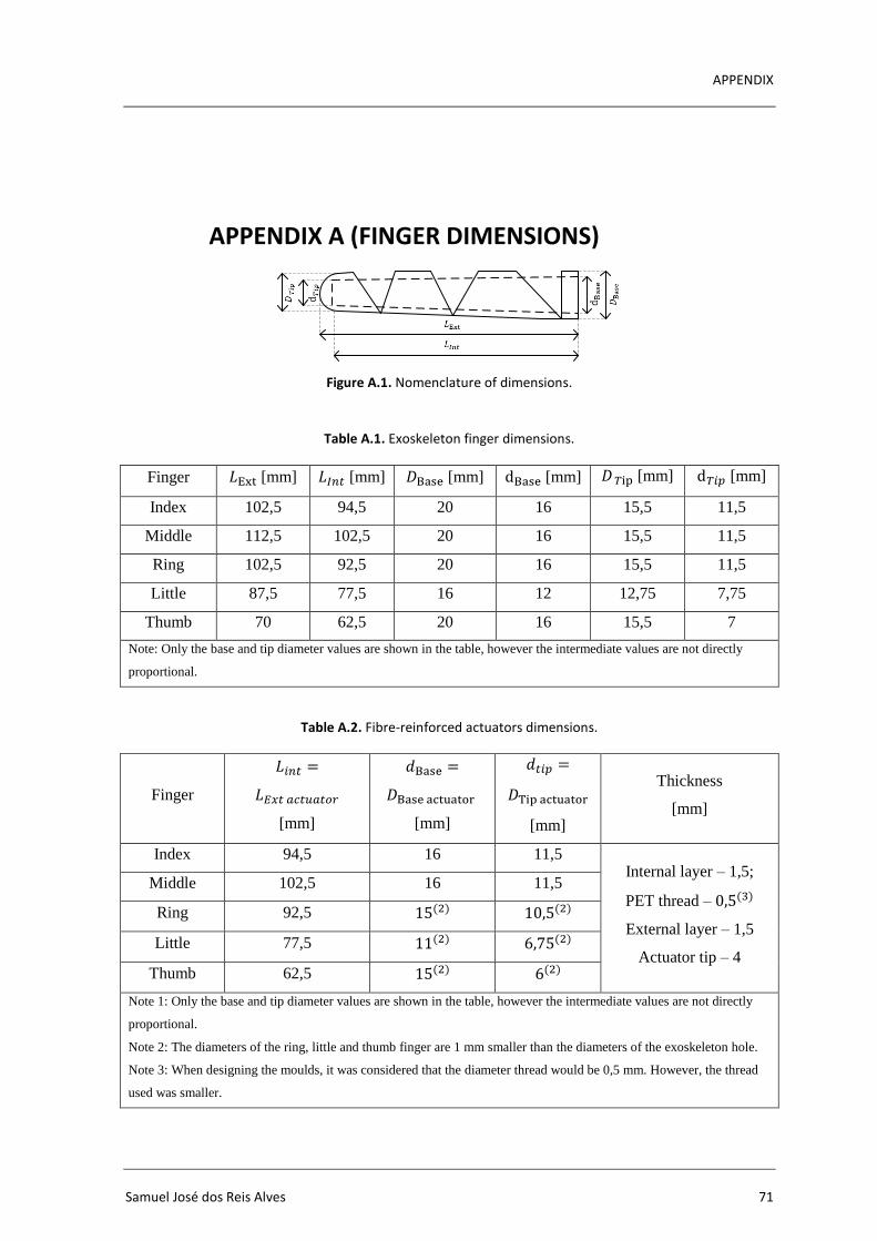
APPENDIX
Samuel José dos Reis Alves 71
APPENDIX A (FINGER DIMENSIONS)
Figure A.1. Nomenclature of dimensions.
Table A.1. Exoskeleton finger dimensions.
Finger 𝐿Ext [mm] 𝐿𝐼𝑛𝑡 [mm] 𝐷Base [mm] dBase [mm] 𝐷 𝑇ip [mm] d𝑇𝑖𝑝 [mm]
Index 102,5 94,5 20 16 15,5 11,5
Middle 112,5 102,5 20 16 15,5 11,5
Ring 102,5 92,5 20 16 15,5 11,5
Little 87,5 77,5 16 12 12,75 7,75
Thumb 70 62,5 20 16 15,5 7
Note: Only the base and tip diameter values are shown in the table, however the intermediate values are not directly
proportional.
Table A.2. Fibre-reinforced actuators dimensions.
Finger
𝐿𝑖𝑛𝑡 =
𝐿𝐸𝑥𝑡 𝑎𝑐𝑡𝑢𝑎𝑡𝑜𝑟
[mm]
𝑑Base =
𝐷Base actuator
[mm]
𝑑𝑡𝑖𝑝 =
𝐷Tip actuator
[mm]
Thickness
[mm]
Index 94,5 16 11,5 Internal layer – 1,5;
PET thread – 0,5(3)
External layer – 1,5
Actuator tip – 4
Middle 102,5 16 11,5
Ring 92,5 15(2) 10,5(2)
Little 77,5 11(2) 6,75(2)
Thumb 62,5 15(2) 6(2)
Note 1: Only the base and tip diameter values are shown in the table, however the intermediate values are not directly
proportional.
Note 2: The diameters of the ring, little and thumb finger are 1 mm smaller than the diameters of the exoskeleton hole.
Note 3: When designing the moulds, it was considered that the diameter thread would be 0,5 mm. However, the thread
used was smaller.

Design and manufacturing of soft robotics mechanisms: improving the reliability of pneumatic-based solutions APPENDIX
72 2020
APPENDIX B (PRINTING PARAMETERS)
Table B.1. Printing parameters.
Parameters Finger exoskeleton –
Filaflex 82A
Hand exoskeleton –
Ninjaflex PLA parts
Nozzle tempearature 235 ºC 240 ºC 210 ºC
Nozzle size 0.35 mm 0.35 mm 0.35 mm
Printing speed 30 mm/s 20 mm/s 40 mm/s
Infill Pattern Concentric Concentric Grid
Infill Density 100 % 100 % 20 %
Layer height 0.2 0.1 0.2
Adhesion type Brim None ∗(1)
Flow material 105 % 105 % 100 %
Type of support None Touching build plate
(70º) ∗(2)
Retraction Off Off On
Heated bed None None None
∗(1) – Figure 4.6: (b), (c), (d), (e) – Raft; (f), (g), (h) – Brim.
∗(2) – Figure 4.6: (b), (c) – None; (d), (e) – Touching buildplate; (f), (g), (h) – None.

APPENDIX
Samuel José dos Reis Alves 73
APPENDIX C (ECOFLEX™ SERIES – TECHNICAL BULLETIN)

Design and manufacturing of soft robotics mechanisms: improving the reliability of pneumatic-based solutions APPENDIX
74 2020
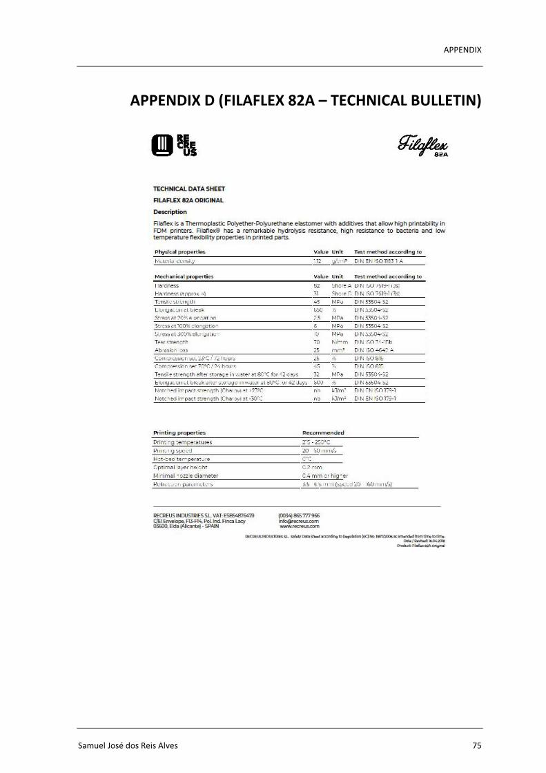
APPENDIX
Samuel José dos Reis Alves 75
APPENDIX D (FILAFLEX 82A – TECHNICAL BULLETIN)
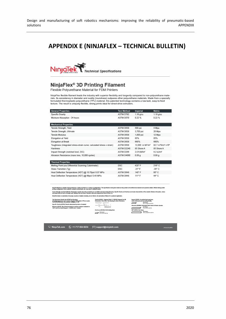
Design and manufacturing of soft robotics mechanisms: improving the reliability of pneumatic-based solutions APPENDIX
76 2020
APPENDIX E (NINJAFLEX – TECHNICAL BULLETIN)