design and manufacturing technology of fuji electric’s ... · pdf filedesign and...
TRANSCRIPT
Design and Manufacturing Technology of Fuji Electric’s Large-Capacity, Air-Cooled Turbine Generator 395
1 INTRODUCTION The capacities of air-cooled, two-pole turbine generators
have increased dramatically. About 10 years ago hydrogen -cooled generator was used in 200 MVA class turbine generators, but nowadays, air-cooled generator is even being used in 300MVA-class and above turbine generators.
Air-cooled generators have a simpler structure than hydrogen-cooled generators and because they require no auxiliary systems such as a hydrogen gas supply system or a sealing oil supply system, the installation, operation and maintenance of air-cooled generators is quick and easy. Furthermore, air-cooled generators are advantageous because their production lead-time is short and initial investment cost is low. Air-cooled turbine generators are suited to combined-cycle power plants that meet the social demand for better environment. Therefore, demands for air-cooled turbine generators are expected to increase just as up to now.
This paper describes the features of excellent design and latest manufacturing technology on Fuji Electric’s large-capacity air-cooled generator.
2 TECHNICAL FEATURES Fuji Electric has worked to develop larger capacity
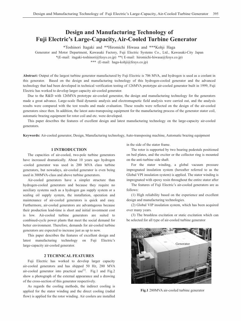
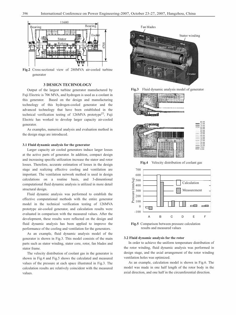
air-cooled generators and has shipped 50 Hz, 280 MVA air-cooled generator into practical use[1]. Fig.1 and Fig.2 show a photograph of the external appearance and a drawing of the cross-section of this generator respectively.
As regards the cooling methods, the indirect cooling is applied for the stator winding and the direct cooling (radial flow) is applied for the rotor winding. Air coolers are installed
in the side of the stator frame. The rotor is supported by two bearing pedestals positioned
on bed plates, and the exciter or the collector ring is mounted on the anti-turbine side shaft.
For the stator winding, a global vacuum pressure impregnated insulation system (hereafter referred to as the Global VPI insulation system) is applied. The stator winding is impregnated with epoxy resin throughout the entire stator after
The features of Fuji Electric’s air-cooled generators are as follows:
(1) High reliability based on the experience and excellent design and manufacturing technologies.
(2) Global VIP insulation system, which has been acquired over many years.
(3) The brushless excitation or static excitation which can be selected for all type of air-cooled turbine generator
Fig.1 280MVA air-cooled turbine generator
Design and Manufacturing Technology of Fuji Electric’s Large-Capacity, Air-Cooled Turbine Generator
*Toshinori Itagaki and **Hiromichi Hiwasa and ***Kohji Haga Generator and Motor Department, Kawasaki Factory, Fuji Electric Systems Co., Ltd., Kawasaki-City Japan
*(E-mail: [email protected]) **( E-mail: [email protected]) *** (E-mail: [email protected])
Abstract: Output of the largest turbine generator manufactured by Fuji Electric is 706 MVA, and hydrogen is used as a coolant in this generator. Based on the design and manufacturing technology of this hydrogen-cooled generator and the advanced technology that had been developed in technical verification testing of 126MVA prototype air-cooled generator built in 1999, Fuji Electric has worked to develop larger capacity air-cooled generator.
Due to the R&D with 126MVA prototype air-cooled generator, the design and manufacturing technology for the generatorsmade a great advance. Large-scale fluid dynamic analysis and electromagnetic field analysis were carried out, and the analysis results were compared with the test results and made evaluation. These results were reflected on the design of the air-cooled generators since then. In addition, the latest auto-transposing equipment for the manufacturing process of the generator stator coil, automatic brazing equipment for rotor coil and etc. were developed.
This paper describes the features of excellent design and latest manufacturing technology on the large-capacity air-cooled generators.
Keywords: Air-cooled generator, Design, Manufacturing technology, Auto-transposing machine, Automatic brazing equipment
International Conference on Power Engineering-2007, October 23-27, 2007, Hangzhou, China396
Fig.2 Cross-sectional view of 280MVA air-cooled turbine generator
3 DESIGN TECHNOLOGY Output of the largest turbine generator manufactured by
Fuji Electric is 706 MVA, and hydrogen is used as a coolant in this generator. Based on the design and manufacturing technology of this hydrogen-cooled generator and the advanced technology that have been established in the technical verification testing of 126MVA prototype[2], Fuji Electric has worked to develop larger capacity air-cooled generator.
As examples, numerical analysis and evaluation method in the design stage are introduced.
3.1 Fluid dynamic analysis for the generator Larger capacity air cooled generators induce larger losses
at the active parts of generator. In addition, compact design and increasing specific utilization increase the stator and rotor losses. Therefore, accurate estimation of losses in the design stage and realizing effective cooling and ventilation are important. The ventilation network method is used in design calculations on a routine basis, and 3-dimentional computational fluid dynamic analysis is utilized in more detail structural design.
Fluid dynamic analysis was performed to establish the effective computational methods with the entire generator model in the technical verification testing of 126MVA prototype air-cooled generator, and calculation results were evaluated in comparison with the measured values. After the development, these results were reflected on the design and fluid dynamic analysis has been applied to improve the performance of the cooling and ventilation for the generators.
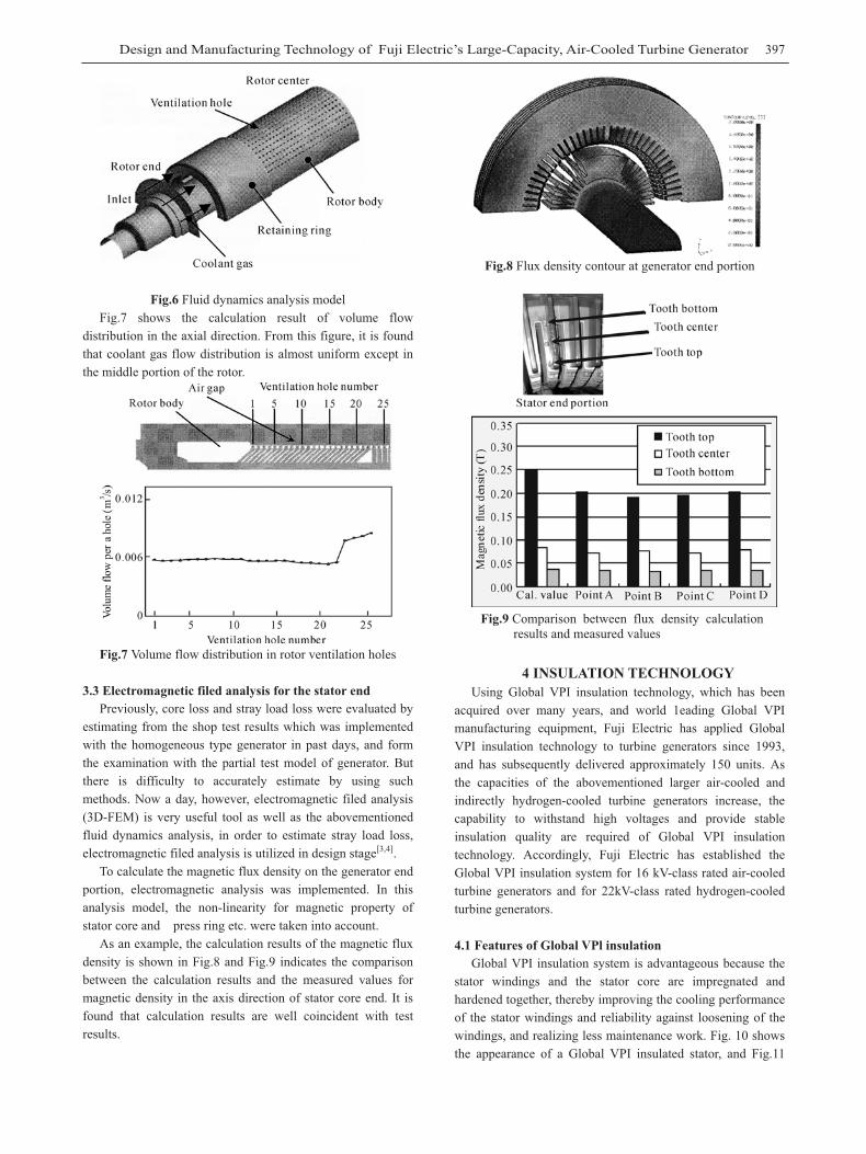
As an example, fluid dynamic analysis model of the generator is shown in Fig.3. This model consists of the main parts such as stator winding, stator core, rotor, fan blades and stator frame.
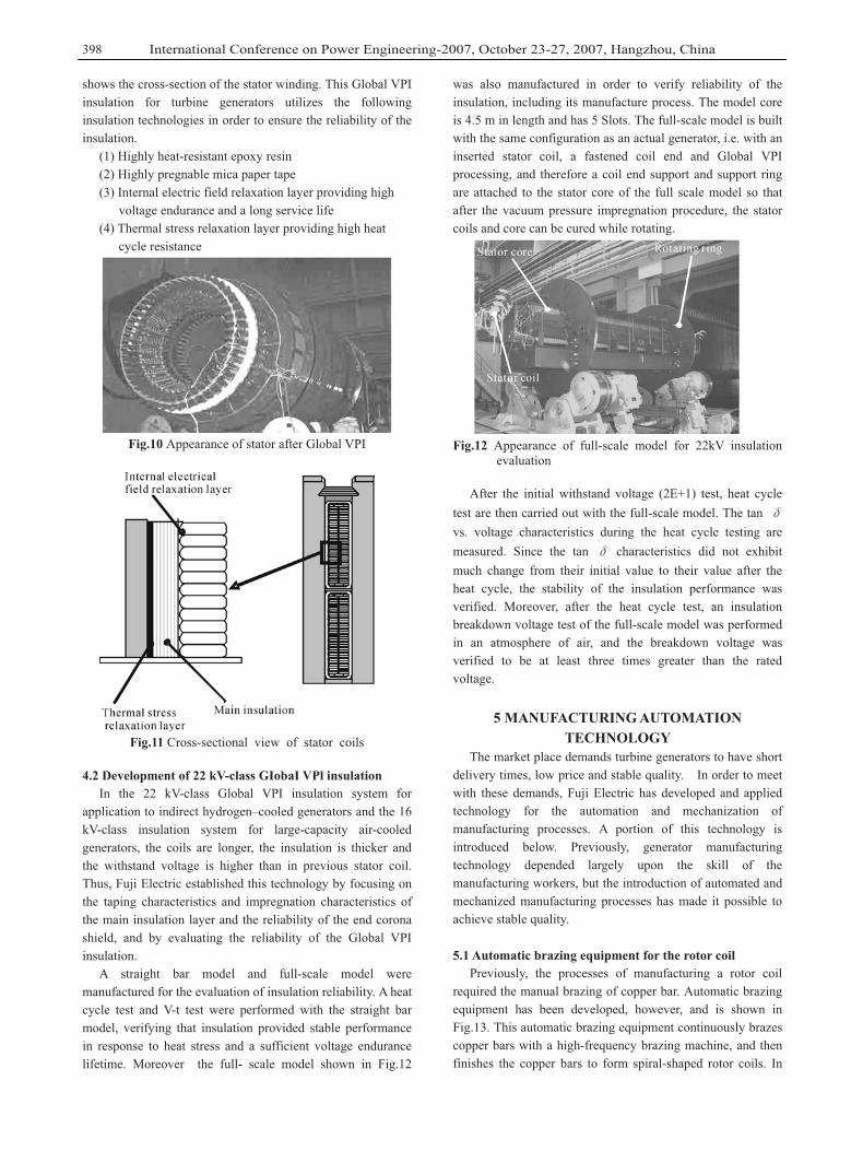
The velocity distribution of coolant gas in the generator is shown in Fig.4 and Fig.5 shows the calculated and measured values of the pressure at each space illustrated in Fig.3. The calculation results are relatively coincident with the measured values.
Fig.3 Fluid dynamic analysis model of generator
Rotor
Fig.4 Velocity distribution of coolant gas
-1000
100200300400500600700
� & 8 $ 7 5
Pres
sure
(mm
Aq)
Calculation
Measurement
Fig.5 Comparison between pressure calculation results and measured values
3.2 Fluid dynamic analysis for the rotor In order to achieve the uniform temperature distribution of
the rotor winding, fluid dynamic analysis was performed in design stage, and the axial arrangement of the rotor winding ventilation holes was optimized.
As an example, calculation model is shown in Fig.6. The model was made in one half length of the rotor body in the axial direction, and one half in the circumferential direction.
Design and Manufacturing Technology of Fuji Electric’s Large-Capacity, Air-Cooled Turbine Generator 397
Fig.6 Fluid dynamics analysis model Fig.7 shows the calculation result of volume flow
distribution in the axial direction. From this figure, it is found that coolant gas flow distribution is almost uniform except in the middle portion of the rotor.
Fig.7 Volume flow distribution in rotor ventilation holes
3.3 Electromagnetic filed analysis for the stator end Previously, core loss and stray load loss were evaluated by
estimating from the shop test results which was implemented with the homogeneous type generator in past days, and form the examination with the partial test model of generator. But there is difficulty to accurately estimate by using such methods. Now a day, however, electromagnetic filed analysis (3D-FEM) is very useful tool as well as the abovementioned fluid dynamics analysis, in order to estimate stray load loss, electromagnetic filed analysis is utilized in design stage[3,4].
To calculate the magnetic flux density on the generator end portion, electromagnetic analysis was implemented. In this analysis model, the non-linearity for magnetic property of stator core and press ring etc. were taken into account.
As an example, the calculation results of the magnetic flux density is shown in Fig.8 and Fig.9 indicates the comparison between the calculation results and the measured values for magnetic density in the axis direction of stator core end. It is found that calculation results are well coincident with test results.
Fig.8 Flux density contour at generator end portion
Fig.9 Comparison between flux density calculation results and measured values
4 INSULATION TECHNOLOGY Using Global VPI insulation technology, which has been
acquired over many years, and world 1eading Global VPI manufacturing equipment, Fuji Electric has applied Global VPI insulation technology to turbine generators since 1993, and has subsequently delivered approximately 150 units. As the capacities of the abovementioned larger air-cooled and indirectly hydrogen-cooled turbine generators increase, the capability to withstand high voltages and provide stable insulation quality are required of Global VPI insulation technology. Accordingly, Fuji Electric has established the Global VPI insulation system for 16 kV-class rated air-cooled turbine generators and for 22kV-class rated hydrogen-cooled turbine generators.
4.1 Features of Global VPl insulation Global VPI insulation system is advantageous because the
stator windings and the stator core are impregnated and hardened together, thereby improving the cooling performance of the stator windings and reliability against loosening of the windings, and realizing less maintenance work. Fig. 10 shows the appearance of a Global VPI insulated stator, and Fig.11
International Conference on Power Engineering-2007, October 23-27, 2007, Hangzhou, China398
shows the cross-section of the stator winding. This Global VPI insulation for turbine generators utilizes the following insulation technologies in order to ensure the reliability of the insulation.
(1) Highly heat-resistant epoxy resin (2) Highly pregnable mica paper tape (3) Internal electric field relaxation layer providing high
voltage endurance and a long service life (4) Thermal stress relaxation layer providing high heat
cycle resistance
Fig.10 Appearance of stator after Global VPI
Fig.11 Cross-sectional view of stator coils
4.2 Development of 22 kV-class GIobaI VPl insulation In the 22 kV-class Global VPI insulation system for
application to indirect hydrogen–cooled generators and the 16 kV-class insulation system for large-capacity air-cooled generators, the coils are longer, the insulation is thicker and the withstand voltage is higher than in previous stator coil. Thus, Fuji Electric established this technology by focusing on the taping characteristics and impregnation characteristics of the main insulation layer and the reliability of the end corona shield, and by evaluating the reliability of the Global VPI insulation.
A straight bar model and full-scale model were manufactured for the evaluation of insulation reliability. A heat cycle test and V-t test were performed with the straight bar model, verifying that insulation provided stable performance in response to heat stress and a sufficient voltage endurance lifetime. Moreover the full- scale model shown in Fig.12
was also manufactured in order to verify reliability of the insulation, including its manufacture process. The model core is 4.5 m in length and has 5 Slots. The full-scale model is built with the same configuration as an actual generator, i.e. with an inserted stator coil, a fastened coil end and Global VPI processing, and therefore a coil end support and support ring are attached to the stator core of the full scale model so that after the vacuum pressure impregnation procedure, the stator coils and core can be cured while rotating.
Fig.12 Appearance of full-scale model for 22kV insulation evaluation
After the initial withstand voltage (2E+1) test, heat cycle test are then carried out with the full-scale model. The tan Evs. voltage characteristics during the heat cycle testing are measured. Since the tan E characteristics did not exhibit much change from their initial value to their value after the heat cycle, the stability of the insulation performance was verified. Moreover, after the heat cycle test, an insulation breakdown voltage test of the full-scale model was performed in an atmosphere of air, and the breakdown voltage was verified to be at least three times greater than the rated voltage.
5 MANUFACTURING AUTOMATION TECHNOLOGY
The market place demands turbine generators to have short delivery times, low price and stable quality. In order to meet with these demands, Fuji Electric has developed and applied technology for the automation and mechanization of manufacturing processes. A portion of this technology is introduced below. Previously, generator manufacturing technology depended largely upon the skill of the manufacturing workers, but the introduction of automated and mechanized manufacturing processes has made it possible to achieve stable quality.
5.1 Automatic brazing equipment for the rotor coil Previously, the processes of manufacturing a rotor coil
required the manual brazing of copper bar. Automatic brazing equipment has been developed, however, and is shown in Fig.13. This automatic brazing equipment continuously brazes copper bars with a high-frequency brazing machine, and then finishes the copper bars to form spiral-shaped rotor coils. In
Design and Manufacturing Technology of Fuji Electric’s Large-Capacity, Air-Cooled Turbine Generator 399
changing over the brazing work from a manual to an automated operation, the copper bar temperature during high-frequency heating and the timing for inserting the brazing filler metal were investigated, and conditional settings for the automated machinery were determined based on such relationships as the material strength and cross-sectional analysis of the brazed portion. Moreover, in the case of a rotor coil copper bar of different dimensions, a brazed sample is fabricated and a strength test performed to verify whether the conditional settings are appropriate and to ensure good quality.
Fig.13 Automatic brazing equipment
5.2 Automatic transposing equipment In order to reduce loss in the stator coil, Roebel
transposition, in other words, strand transposition, is utilized. Previously, the tasks of strand cutting, forming, and transposing were performed manually for each work process. An automatic transposing equipment has been developed, however, and is shown in Fig.14. This automatic transposing equipment automates the series of work processes from strand cutting, stripping the insulation from the strand ends, strand forming, transposing, and inserting of insulation material, to strand bundling. When strand wire and insulating material are input into the equipment, the equipment transposes the strands and outputs a coil. Moreover, the automatic transposing equipment is designed with a proprietary transposing mechanism to realize homogeneity of the transposing.
Fig.14 Automatic transposing equipment
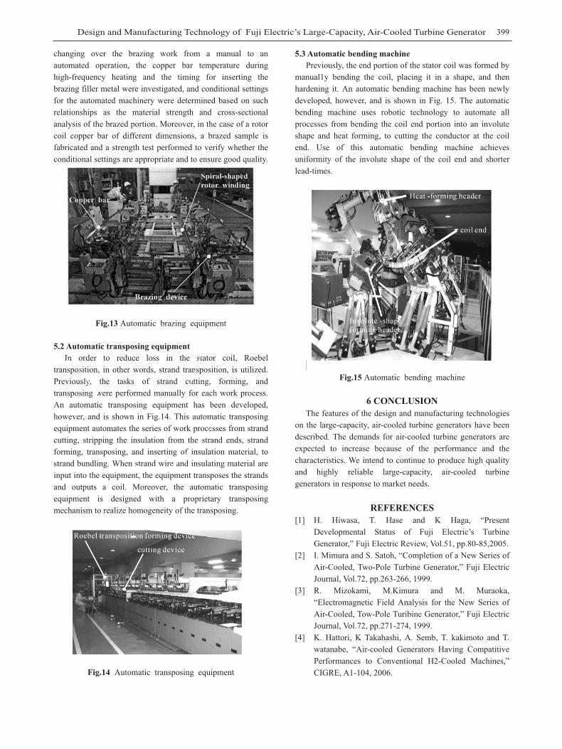
5.3 Automatic bending machine Previously, the end portion of the stator coil was formed by
manual1y bending the coil, placing it in a shape, and then hardening it. An automatic bending machine has been newly developed, however, and is shown in Fig. 15. The automatic bending machine uses robotic technology to automate all processes from bending the coil end portion into an involute shape and heat forming, to cutting the conductor at the coil end. Use of this automatic bending machine achieves uniformity of the involute shape of the coil end and shorter lead-times.
Heat-forming header
coil end
Involute-shapeforming header
Spiral-shaped rotor winding
Copper bar
Fig.15 Automatic bending machine
6 CONCLUSION The features of the design and manufacturing technologies
on the large-capacity, air-cooled turbine generators have been described. The demands for air-cooled turbine generators are expected to increase because of the performance and the characteristics. We intend to continue to produce high quality and highly reliable large-capacity, air-cooled turbine generators in response to market needs.
Brazing device
REFERENCES[1] H. Hiwasa, T. Hase and K Haga, “Present
Developmental Status of Fuji Electric’s Turbine Generator,” Fuji Electric Review, Vol.51, pp.80-85,2005.
[2] I. Mimura and S. Satoh, “Completion of a New Series of Air-Cooled, Two-Pole Turbine Generator,” Fuji Electric Journal, Vol.72, pp.263-266, 1999.
[3] R. Mizokami, M.Kimura and M. Muraoka, “Electromagnetic Field Analysis for the New Series of Air-Cooled, Tow-Pole Turibine Generator,” Fuji Electric Journal, Vol.72, pp.271-274, 1999.
[4] K. Hattori, K Takahashi, A. Semb, T. kakimoto and T. watanabe, “Air-cooled Generators Having Compatitive Performances to Conventional H2-Cooled Machines,” CIGRE, A1-104, 2006.