design and optimization of rectangular microstrip patch · pdf filedesign and optimization of...
TRANSCRIPT

International Journal of Applied Engineering Research ISSN 0973-4562 Volume 11, Number 7 (2016) pp 4679-4687 © Research India Publications. http://www.ripublication.com
4679
Design and Optimization of Rectangular Microstrip Patch Array Antenna Using Frequency Selective Surfaces for 60 GHz
Ehab Dheyab Department of Electronics and Communications Engineering,
Al-Ahliyya Amman University, Amman, Jordan.
Nidal Qasem* Department of Electronics and Communications Engineering,
Al-Ahliyya Amman University, Amman, Jordan. *Corresponding author
Abstract Microstrip Patch Antennas (MPAs) are mostly known for their versatility in terms of possible geometries that makes them applicable for many different situations. The lightweight construction and the suitability for integration with microwave integrated circuits are two more of their numerous advantages. Patch antenna has a narrow bandwidth so it has a complexity in tunings. Also, MPAs are famous for their poor gain. So, there is a requirement to increase the bandwidth and gain of Microstrip Patch Antenna (MPA). This paper presents the application of Frequency Selective Surfaces (FSSs) in rectangular Microstrip Patch Array Antenna (MPAA) as a solution to improve radiation parameters of the array. A rectangular MPAA between two FSSs were proposed for 60 GHz applications. Several parameters have been significantly improved, in particular the gain, bandwidth, return loss, and radiation pattern, compared with an optimized antenna. Numerical and simulation results are presented. Keywords: 60 GHz, Frequency selective surface, Gain enhancement, Microstrip patch antenna, Wireless communication. Introduction Over the past decades, an unprecedented growth of wireless communication services driven by the development of advanced and “bandwidth-hungry” technologies have been witnessed. The industry has evolved from pagers and cell-phones to cutting-edge Personal Digital Assistants (PDAs), Set-top-Boxes (STBs), Personal Computers (PCs), and other devices capable of delivering high-speed multimedia content while connected to fast and reliable broadband Wireless Local Area Networks (WLAN) and Wireless Personal Area Networks (WPAN). In the attempt of keeping up with the huge amount of data traffic required by the most recent and high bitrate multimedia services, wireless networks have increased their capacity at the pace of ten times every five years and are expected to break the 1 Gigabit per second (Gbit/s) limit in the near future [1]. Availability of 7 GHz unlicensed spectrum, low interference levels, small form factor of the antenna subsystem, and other technology-enablers make 60 GHz band the most promising candidate to support multi-gigabit data rates [2]. Designing and fabricating antennas at 60 GHz frequency, with size of the order
of few microns, has a challenge due to the small distance between the radiating elements, surrounding metal layers, and substrate. The radiation losses and conduction losses are extremely large due to substrate absorption and conduction currents thus these antennas have very high losses and very low gains [3]. MPA has so many advantages in wireless communication like low cost, compact, and easy to manufacture. So, it has attracted many attentions from researchers. To overcome the inherent disadvantages of narrow bandwidth and surface wave loss, many works have been done like taking advantage of stacked patch or opening an air cavity in the multilayer substrates. However, these methods always come to a price that the complexity and fabrication cost rises [4]. FSSs are planar periodic structures which exhibit reflection and/or transmission properties as a function of frequency. They behave as electromagnetic filters, passive or active, selectively reflecting, or attenuating a desired frequency band [5]. Frequency Selective Surface (FSS) structure has a phenomenon with high impedance surface that reflects the plane wave in-phase and suppresses surface wave. Therefore, a rectangular MPA with FSS structure can improve its radiation efficiency, bandwidth, gain, and reduce the sidelobe and backlobe level in its radiation pattern [6]. This paper proposes to design a single rectangular MPA and a rectangular MPAA with FSSs for 60 GHz to get a high gain, return loss, and bandwidth. The 60 GHz band suffers from severe attenuation due to propagation. Let alone the oxygen absorption, which may be neglected for short radio links, the free-space path loss occurring at 60 GHz is in the order of 20-30 dB higher than that of a WLAN operating at 2.5 GHz. Furthermore, due to the very large transmission bandwidth, up to 2.16 GHz, the total noise power is by far greater than that of systems operating at lower frequencies. These combined factors result in a poor link budget [7]. Trying to obtain a best result, a three layouts have been used: (1) The antenna with ground plane. (2) Stop-band FSS as ground plane. (3) Pass-band FSS as superstrate. The idea is to reflects the plane wave in-phase and reduce the surface waves to further improve the parameters of the antenna. Design of Antenna In this paper, Antenna Magus software tool will be used to helps accelerate the antenna design and modelling process [8].
International Journal of Applied Engineering Research ISSN 0973-4562 Volume 11, Number 7 (2016) pp 4679-4687 © Research India Publications. http://www.ripublication.com
4680
For the design of a single rectangular MPA, essential parameters are set as:
Frequency of operation ( ) = 60 ; Dielectric constant of the substrate ( ) = 2.2; Height of dielectric substrate (h) = 0.1 ; Input impedance ( ) = 50 .
Table I presented parameter values were calculated by Antenna Magus and confirmed through following equations [9]:
1 12 (1)
0.412. .
. . (2)
(3)
2 (4)
(5)
Where, is the effective dielectric constant, is dielectric constant of substrate, h is height of dielectric substrate, is width of the patch, is effective length, is actual length, and the dimensions of the patch along its length have been extended on each end by a distance . Dimensions of patch, feed line, and space between them are demonstrated in Figure 1.
Figure 1: Dimensions of patch and feed line.
Table I: Parameter values were calculated by Antenna Magus (in mm).
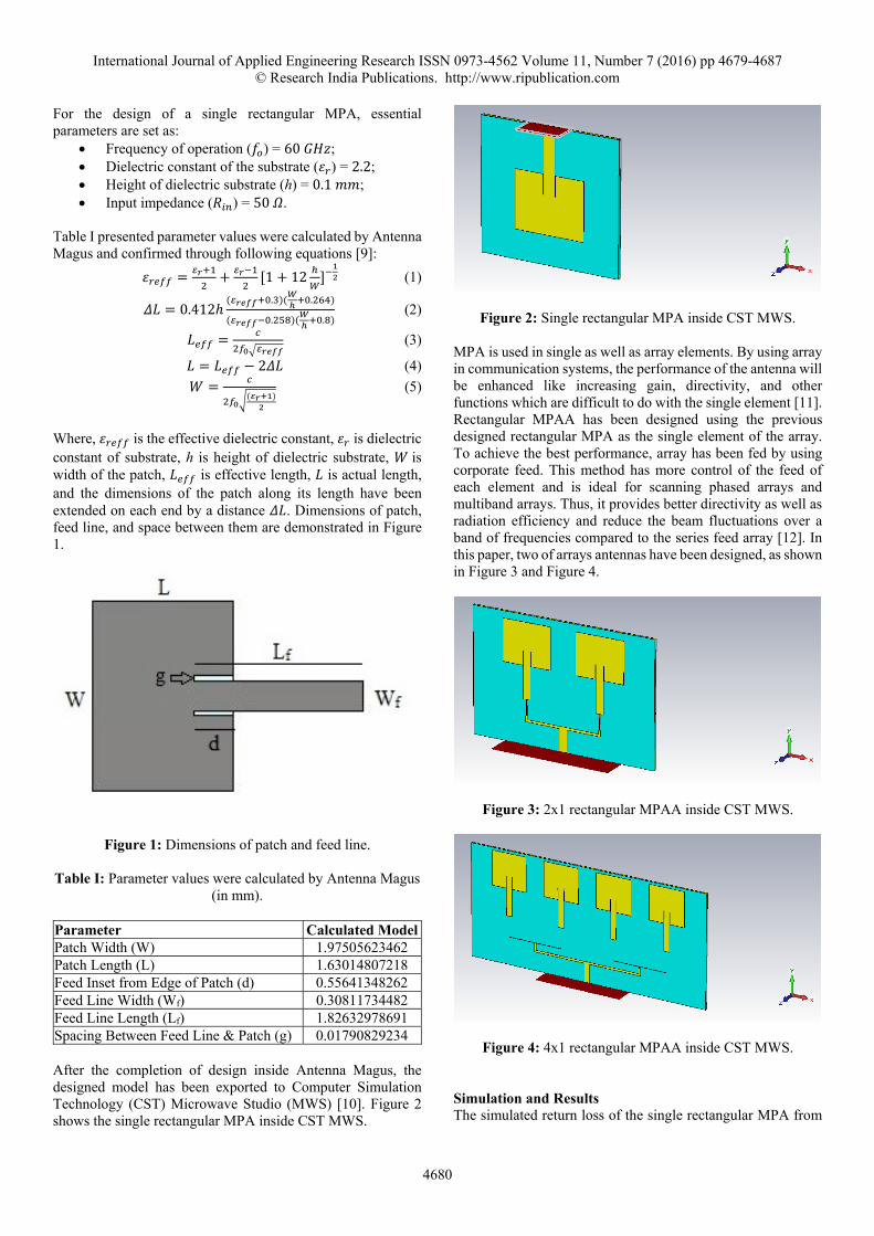
Parameter Calculated ModelPatch Width (W) 1.97505623462 Patch Length (L) 1.63014807218 Feed Inset from Edge of Patch (d) 0.55641348262 Feed Line Width (Wf) 0.30811734482 Feed Line Length (Lf) 1.82632978691 Spacing Between Feed Line & Patch (g) 0.01790829234 After the completion of design inside Antenna Magus, the designed model has been exported to Computer Simulation Technology (CST) Microwave Studio (MWS) [10]. Figure 2 shows the single rectangular MPA inside CST MWS.
Figure 2: Single rectangular MPA inside CST MWS.
MPA is used in single as well as array elements. By using array in communication systems, the performance of the antenna will be enhanced like increasing gain, directivity, and other functions which are difficult to do with the single element [11]. Rectangular MPAA has been designed using the previous designed rectangular MPA as the single element of the array. To achieve the best performance, array has been fed by using corporate feed. This method has more control of the feed of each element and is ideal for scanning phased arrays and multiband arrays. Thus, it provides better directivity as well as radiation efficiency and reduce the beam fluctuations over a band of frequencies compared to the series feed array [12]. In this paper, two of arrays antennas have been designed, as shown in Figure 3 and Figure 4.
Figure 3: 2x1 rectangular MPAA inside CST MWS.
Figure 4: 4x1 rectangular MPAA inside CST MWS.
Simulation and Results The simulated return loss of the single rectangular MPA from

International Journal of Applied Engineering Research ISSN 0973-4562 Volume 11, Number 7 (2016) pp 4679-4687 © Research India Publications. http://www.ripublication.com
4681
CST MWS is shown in Figure 5. At 60 GHz, a return loss of ‐12 dB is achieved. The Voltage Standing Wave Ratio (VSWR) is equal to 1.67 can be calculated by using the following equation:
(6)
Figure 5: Return loss for single rectangular MPA. The bandwidth can be calculated from the return loss plot [9]. The bandwidth of the single rectangular MPA is calculated to be 1.05 GHz and a center frequency of 59.85 GHz is obtained which is very close to the desired design frequency of 60 GHz. The return loss of 2x1 rectangular MPAA was measured. The simulation showed that the antenna has -11.3 dB return loss and VSWR is equal to 1.748, as shown in Figure 6. The bandwidth for the 2x1 rectangular MPAA is equal to 0.55 GHz.
Figure 6: Return loss for 2x1 rectangular MPAA. Figure 7 shows the return loss of 4x1 rectangular MPAA. The simulation showed that the antenna has a -12 dB return loss, VSWR is equal to 1.67, and the bandwidth is equal to 0.625 GHz.
Figure 7: Return loss for 4x1 rectangular MPAA.
MPAs have poor gain; this is because antenna gain is affected by substrate thickness and relative dielectric constant [10]. Gain is inversely proportional to and directly proportional to substrate thickness. For the designed single rectangular MPA, the gain is 7.15 dB, as shown in Figure 8.
Figure 8: Gain for single rectangular MPA. The radiation pattern of a single patch is characterized by a single main lobe of moderate beam width. Frequently, the beam widths in the azimuth and elevation planes are similar, resulting in a fairly circular beam, although this is by no means universal. The beam widths can be manipulated to produce an antenna with higher or lower gain, depending on the requirements [13]. The 3 dB beam width, for single rectangular MPA is about 75.8o, as shown in Figure 9.
Figure 9: Radiation pattern for single rectangular MPA. The 3D graph of the gain for 2x1 rectangular MPAA is shown in Figure 10, which is equal to 9.21 dB.
Figure 10: Gain for 2x1 rectangular MPAA.

International Journal of Applied Engineering Research ISSN 0973-4562 Volume 11, Number 7 (2016) pp 4679-4687 © Research India Publications. http://www.ripublication.com
4682
Antennas with wide beam widths typically have low gain and antennas with narrow beam widths tend to have higher gain. So, an antenna that directs most of its energy into a narrow beam will have a higher gain [14]. Therefore, the 3 dB beam width for the 2x1 rectangular MPAA is decreased to 41.9o, as shown in Figure 11.
Figure 11: Radiation pattern for 2x1 rectangular MPAA. The gain of 11.6 dB is achieved from 4x1 rectangular MPAA, as shown in Figure 12. The 3 dB beam width is decreased to 20.6o, as shown in Figure 13.
Figure 12: Gain for 4x1 rectangular MPAA.
Figure 13: Radiation pattern for 4x1 rectangular MPAA.
Antenna Optimization: In this paper, the main goals of optimization are to enhance
performance and manufacturing process of antennas. Where the laser accuracy in manufacturing antennas is 0.08 mm [15]. Therefore, the optimization procedures for antenna are through maximize some parameters and minimize some others. Table II summarized the optimized parameters for single rectangular MPA procedure.
Table II: Parameter values after optimization (in mm).
Parameter Optimized ValuePatch Width (W) 2 Patch Length (L) 1.62 Feed Inset from Edge of Patch (d) 0.5 Feed Line Width (Wf) 0.3 Feed Line Length (Lf) 1.8 Spacing between Feed Line & Patch (g) 0.1 For rectangular MPAA, the spacing between the antenna elements plays a major role in the design. Too large a spacing results in the presence of grating lobes which is undesirable in most instances. On the other hand, too close a spacing leads to broader beam width which may be unacceptable. Smaller spacing also reduces the amount of space for the feed network. Hence, the space between the elements should be adjusted properly. To obtain maximum additive radiating fields the separation between the elements should be about λ/2 [16]. Table III shows the difference in parameters values before and after optimization for corporate feed for MPAA, as shown in Figure 14. Table III: Parameter values of optimization corporate feed (in
mm).
4x1 Rectangular MPAA
2x1 Rectangular MPAA
Parameter Cal. Model
Opt. Value
Cal. Model
Opt. Value
Feed Line Length 0.456 0.5 0.456 1 Feed Line Width 0.308 0.5 0.308 0.2 Matching LineLength
0.456 0.5 0.456 0.5
Matching LineWidth
0.308 0.3 0.308 0.3
Feed Line-2Length
0.194 0.2 0.188 0.2
Feed Line-2 Width 0.011 0.1 0.089 0.1 Matching Line-2Length
0.194 0.2 0.958 1
Matching Line-2Width
0.011 0.1 0.032 0.1
Feed Line-3Length
0.188 0.2
Feed Line-3 Width 0.089 0.1 Matching line-3Length
0.972 1
Matching Line-3Width
0.008 0.1

International Journal of Applied Engineering Research ISSN 0973-4562 Volume 11, Number 7 (2016) pp 4679-4687 © Research India Publications. http://www.ripublication.com
4683
Figure 14: Corporate feed for MPAA.
Simulation and Results Figure 15, shows the return loss and bandwidth for single rectangular MPA after optimization. At 60 GHz, a return loss of ‐22 dB is achieved, VSWR is equal to 1.173, and the bandwidth is equal to 1.375 GHz. In comparison to the antenna before optimization the parameters have been enhanced.
Figure 15: Return loss for optimized single rectangular MPA. For 2x1 rectangular MPAA, good enhancements have been observed. Where, the return loss is -22.85 dB, VSWR is equal to 1.15, and bandwidth increases to 1.15 GHz, as shown in Figure 16.
Figure 16: Return loss for 2x1 rectangular MPAA after optimization.
Also, significant enhancement results have been observed for 4x1 rectangular MPAA after optimization. Where, the return loss is -32.7 dB, VSWR is equal to 1.047, and bandwidth becomes 1.3 GHz, as shown in Figure 17.
Figure 17: Return loss for 4x1 rectangular MPAA after optimization.
Optimization for single rectangular MPA could not solve gain problem, where gain is increased by 0.12 dB, as shown in Figure 18, Which means that this antenna still suffers from low gain. The 3 dB beamwidth is about 73.5o, as shown in Figure 19.
Figure 18: Gain for optimized single rectangular MPA.
Figure 19: Radiation pattern for optimized single rectangular MPA.
Figure 20, shows a gain for the 2x1 rectangular MPAA after optimization. The gain is increased to 10.7 dB. Therefore, the 3 dB is decreased to 26.8o, as shown in Figure 21.
Figure 20: Gain for 2x1 rectangular MPAA after optimization.

International Journal of Applied Engineering Research ISSN 0973-4562 Volume 11, Number 7 (2016) pp 4679-4687 © Research India Publications. http://www.ripublication.com
4684
Figure 21: Radiation pattern for 2x1 rectangular MPAA after optimization.
The gain of 4x1 rectangular MPAA is increased to 13.5 dB and beam width of 12.2o is achieved after optimization, as shown in Figure 22 and Figure 23 respectively.
Figure 22: Gain of 4x1 rectangular MPAA after optimization.
Figure 23: Radiation pattern for 4x1 rectangular MPAA after optimization.
Proposed FSS This paper is proposing a configuration of MPAA integrated with FSS. This configuration presents improved performance of many parameters for 60 GHz applications. To improve some parameters such as gain, bandwidth, and return loss. FSS has been used as a reflector formed by a stop-band FSS and as superstrate formed by a pass-band FSS structure. The proposed FSS is designed to operate in the frequency range 57–64 GHz, with resonance frequency at 60 GHz. The chosen geometry was the Square Loop (SL) element in both FSS which has a best performance over other simple geometry shapes [6]. The material used was the copper ( 3). Figure 24 illustrates the geometry of the FSS used in the study [15]. The dimensions of the designed SL FSS are as follow (all in mm): p = 1.4, d = 1.2,
g = 0.2, and s = 0.1 [17].
Figure 24: The stop-band SL FSS element parameters, where the green color is the dielectric substrate and the brown is the
conductor (copper). For the Transverse Magnetic (TM)-wave incidence the response should be identical to Transverse Electric (TE)-wave incidence response. The SL FSS has a dual polarized response because of to the similarity in unit cell of SL FSS in X-Y axis. Therefore, the TE-wave incidence has been demonstrated only [16]. Figure 25 and Figure 26 show the reflection and transmission response of the SL FSS for TE-mode for different incidence angles ranging between 0°-80° inside CST MWS respectively. Both responses are stable with angular variation.
Figure 25: The reflection response (S11) for the stop-band SL
FSS.
Figure 26: The transmission response (S21) for the stop-band
SL FSS.

International Journal of Applied Engineering Research ISSN 0973-4562 Volume 11, Number 7 (2016) pp 4679-4687 © Research India Publications. http://www.ripublication.com
4685
For a pass-band FSS, it can be achieved by using the Babinet duals for Figure 24. Providing that the structure is symmetrical Babinet’s principle can be employed to change from a stop-band FSS to a pass-band FSS, the conductive and non-conductive space are reversed [18]. Figure 27 illustrates the proposed configuration for a rectangular MPA with FSSs design. Three layouts have been used: (1) The antenna with ground plane. (2) Stop-band FSS as ground plane to reflect the plane wave in-phase. (3) Pass-band FSS as superstrate to reduce the surface waves.
Figure 27: A single rectangular MPA between two FSSs. Simulation and Results for Rectangular MPA with FSSs For the proposed configuration the Gap is varied to obtain the optimum distance between the MPA and FSS. The best gap for single rectangular MPA is 2 mm for Gap 1 and Gap 2. Thus, the return loss is -56 dB and bandwidth is improved to 1.45 GHz, as shown in Figure 28.
Figure 28: Return loss for single rectangular MPA with FSSs. Significantly, gain is increased to 10.8 dB and beam width of 76.1o is achieved, as shown in Figure 28 and Figure 29 respectively.
Figure 29: Gain for single rectangular MPA with FSSs.
Figure 30: Radiation pattern for single rectangular MPA with FSSs.
For more promising results, rectangular MPAA is used with FSSs. For 2x1 rectangular MPAA, the best values for the gaps 1 and 2 are 1.9 mm and 0.5 mm, respectively. For this configuration, the return loss is -35 dB and the bandwidth is increased to 1.6 GHz at 60.5 GHz frequency, as shown in Figure 30. The gain has been increased to 14.9 dB and beam width of 27.3o is achieved, as shown in Figure 31 and Figure 32 respectively.
Figure 31: Return loss for 2x1 rectangular MPAA with FSSs.
Figure 32: Gain for 2x1 rectangular MPAA with FSSs.
Figure 33: Radiation pattern for 2x1 rectangular MPAA with FSSs.
International Journal of Applied Engineering Research ISSN 0973-4562 Volume 11, Number 7 (2016) pp 4679-4687 © Research India Publications. http://www.ripublication.com
4686
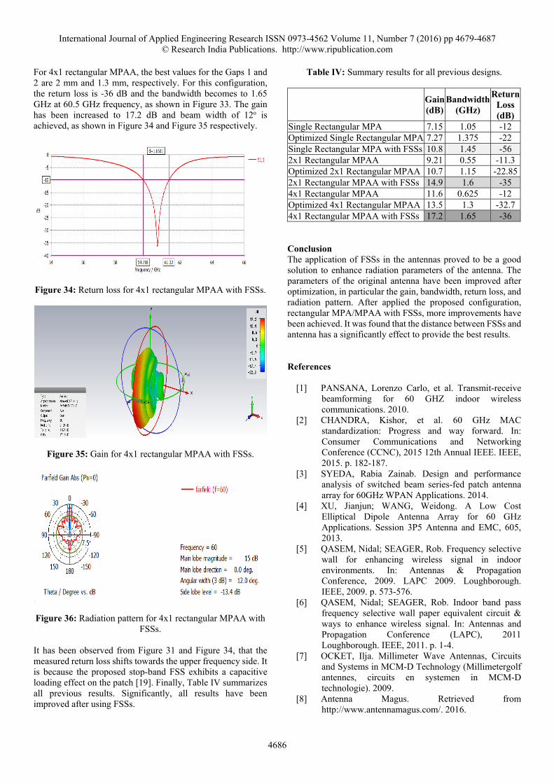
For 4x1 rectangular MPAA, the best values for the Gaps 1 and 2 are 2 mm and 1.3 mm, respectively. For this configuration, the return loss is -36 dB and the bandwidth becomes to 1.65 GHz at 60.5 GHz frequency, as shown in Figure 33. The gain has been increased to 17.2 dB and beam width of 12o is achieved, as shown in Figure 34 and Figure 35 respectively.
Figure 34: Return loss for 4x1 rectangular MPAA with FSSs.
Figure 35: Gain for 4x1 rectangular MPAA with FSSs.
Figure 36: Radiation pattern for 4x1 rectangular MPAA with FSSs.
It has been observed from Figure 31 and Figure 34, that the measured return loss shifts towards the upper frequency side. It is because the proposed stop-band FSS exhibits a capacitive loading effect on the patch [19]. Finally, Table IV summarizes all previous results. Significantly, all results have been improved after using FSSs.
Table IV: Summary results for all previous designs.
Gain (dB)
Bandwidth(GHz)
ReturnLoss (dB)
Single Rectangular MPA 7.15 1.05 -12 Optimized Single Rectangular MPA 7.27 1.375 -22 Single Rectangular MPA with FSSs 10.8 1.45 -56 2x1 Rectangular MPAA 9.21 0.55 -11.3 Optimized 2x1 Rectangular MPAA 10.7 1.15 -22.852x1 Rectangular MPAA with FSSs 14.9 1.6 -35 4x1 Rectangular MPAA 11.6 0.625 -12 Optimized 4x1 Rectangular MPAA 13.5 1.3 -32.7 4x1 Rectangular MPAA with FSSs 17.2 1.65 -36 Conclusion The application of FSSs in the antennas proved to be a good solution to enhance radiation parameters of the antenna. The parameters of the original antenna have been improved after optimization, in particular the gain, bandwidth, return loss, and radiation pattern. After applied the proposed configuration, rectangular MPA/MPAA with FSSs, more improvements have been achieved. It was found that the distance between FSSs and antenna has a significantly effect to provide the best results. References
[1] PANSANA, Lorenzo Carlo, et al. Transmit-receive beamforming for 60 GHZ indoor wireless communications. 2010.
[2] CHANDRA, Kishor, et al. 60 GHz MAC standardization: Progress and way forward. In: Consumer Communications and Networking Conference (CCNC), 2015 12th Annual IEEE. IEEE, 2015. p. 182-187.
[3] SYEDA, Rabia Zainab. Design and performance analysis of switched beam series-fed patch antenna array for 60GHz WPAN Applications. 2014.
[4] XU, Jianjun; WANG, Weidong. A Low Cost Elliptical Dipole Antenna Array for 60 GHz Applications. Session 3P5 Antenna and EMC, 605, 2013.
[5] QASEM, Nidal; SEAGER, Rob. Frequency selective wall for enhancing wireless signal in indoor environments. In: Antennas & Propagation Conference, 2009. LAPC 2009. Loughborough. IEEE, 2009. p. 573-576.
[6] QASEM, Nidal; SEAGER, Rob. Indoor band pass frequency selective wall paper equivalent circuit & ways to enhance wireless signal. In: Antennas and Propagation Conference (LAPC), 2011 Loughborough. IEEE, 2011. p. 1-4.
[7] OCKET, Ilja. Millimeter Wave Antennas, Circuits and Systems in MCM-D Technology (Millimetergolf antennes, circuits en systemen in MCM-D technologie). 2009.
[8] Antenna Magus. Retrieved from http://www.antennamagus.com/. 2016.

International Journal of Applied Engineering Research ISSN 0973-4562 Volume 11, Number 7 (2016) pp 4679-4687 © Research India Publications. http://www.ripublication.com
4687
[9] ASWAD, Fadhil M., et al. Design of rectangular microstrip patch antenna with two enhancements (bandwidth and gain). Australian Journal of Basic and Applied Sciences (AJBAS), 2015, 9.5: 166-170.
[10] C.S.T. Microwave Studio. Retrieved from https://www.cst.com/Products/CSTMWS. 2016.
[11] SINGH, Kuldeep Kumar; Gupta, S. C. Design and Simulation of Microstrip patch array antenna for C Band Application at IMT (4400-4900 MHz) advanced spectrum with Series feed and parallel feed. International Journal of Scientific & Engineering Research, 2013, 4.12.
[12] Ogherohwo, E. P.; Adeniran, A. O. Design and Investigation of Corporate Feed 4x2 Square Array Microstrip Antennas at S-Band. International Journal of Computer Applications, 2012, 53.13.
[13] Janarthanan, R.; Vinayagapriya, S. High Gain Microstrip Array Antenna For WLAN Applications. 2015.
[14] WU, Bae-Ian, et al. A study of using metamaterials as antenna substrate to enhance gain. Progress In Electromagnetics Research, 2005, 51: 295-328.
[15] REDDY, M. Janga; Nagesh Kumar, D. Multi‐objective particle swarm optimization for generating optimal trade‐offs in reservoir operation. Hydrological processes, 2007, 21.21: 2897-2909.
[16] ALMEIDA FILHO, Valdez A.; CAMPOS, Antonio Luiz PS. Performance optimization of microstrip antenna array using frequency selective surfaces. Journal of Microwaves, Optoelectronics and Electromagnetic Applications, 2014, 13.1: 31-46.
[17] ALDORGAM, Emran; QASEM, Nidal; ALZOU’BI, Hadeel. Overcoming the Influence of Human Shadowing via Modified Building Using Frequency Selective Wallpapers for 60 GHz. In 11th Research World International Conference, Riyadh, Saudi Arabia, 22nd February 2016, pp. 24-29, ISBN: 978-93-85973-43-7.
[18] M. J. Archer, \Wave reactance of thin planar strip gratings," Int. J. Electronics, vol. 58, no. 2, pp. 197{230, 1985.
[19] LI, Houmin. Numerical Analysis of Electromagnetic Textiles and Application in Emergency Communication Network. 2011. PhD Thesis. Auburn University.