design and rapid manufacturing of patient-specific spinal ... · pdf filedesign and rapid...
TRANSCRIPT

Proceedings in Manufacturing Systems, Volume 7, Issue 2, 2012
ISSN 2067-9238
DESIGN AND RAPID MANUFACTURING OF PATIENT-SPECIFIC SPINAL SURGICAL GUIDES: A SURVEY
Diana POPESCU1.*, Dorel Florea ANANIA2, Cătălin Gheorghe AMZA3, Dumitru Titi CICIC4
1) Lecturer, PhD, Machine and Production Systems Department, University Politehnica of Bucharest, Bucharest, Romania 2) Lecturer, PhD, Machine and Production Systems Department, University Politehnica of Bucharest, Bucharest, Romania
3) Assistant Prof, PhD, Materials Technology and Welding Department, University Politehnica of Bucharest, Bucharest, Romania 4) Lecturer, PhD, Materials Technology and Welding Department, University Politehnica of Bucharest, Bucharest, Romania
Abstract: The approach of customizing the surgical instrumentations and using them along with com-puter-aided surgical planning and advanced imagining techniques for increasing the accuracy and reli-ability of surgical procedures represents a trend in the medical field. It implies cooperation between en-gineers and medical specialists (radiologists, surgeons, etc.) for all the process steps: computer tomogra-phy/magnetic resonance imaging (CT/MRI) scanning of the patient, medical modelling of the anatomical areas of interest, planning surgery and designing the guide, choosing the material and manufacturing process, building the guide, sterilizing and using it in the operation room. Patient-specific guides can mach exactly patient bone structures and help materializing the planned trajectory for drilling, tapping or cutting. Therefore, these guides improve accuracy of the surgical procedure, helping the surgeons to better orient during intervention, decreasing the surgery time, costs and risks of infections. The main ob-jective of the current paper is to present a review of different patient-specific guides used for pedicle screws insertion in human spine. The paper investigates the design criteria (anatomical landmarks sys-tem, stability, precision, unique placement, etc.), material and Rapid Manufacturing issues related to this application field and presents critical views on different surgical guides designs. Based on this analysis, several proposals for improving the spinal drill guides placement accuracy are presented. Key words: rapid prototyping, design, surgical guides, survey, accuracy, pedicle screws, spine.
1. INTRODUCTION1 Rapid Manufacturing (RM) processes (such as
Stereolithography − SLA, 3D Printing − 3DP, Fused Deposition Modelling- FDM or Selective Laser Sintering − SLS, to mention only the most frequently used) build objects in an additive manner by successively adding horizontal layers of material which are corresponding to the sections created by the intersection of a 3D CAD model with parallel planes oriented perpendicular to the building direction [1 and 2]. These layers of material are formed by selectively solidifying a fotocurable liquid resin, laser sintering powder material, depositing ther-moplastics extruded through a nozzle or bounding pow-der materials using a liquid binder. This particular method of generating solid objects allows building geo-metrical complex prototypes otherwise difficult to obtain using traditional manufacturing technologies, which recommends it for medical applications where the patient specific anatomy (available by computer tomography – CT or magnetic resonance imaging – MRI) is imposing an individual solution (i.e. prototype) for each pa-
* Corresponding author: Splaiul Independenţei 313, Sector 6, 060042, Bucharest, Romania; Tel.: 0040214029759…; Fax: 0040214029759…. E-mail addresses: [email protected] (D. Popescu), [email protected] (D.F.Anania), [email protected] (C.Gh.Amza), [email protected] (D.T. Cicic))
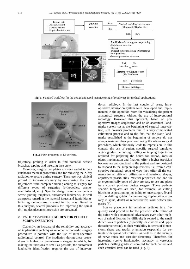
tient/clinical case [3]. The standard workflow for obtain-ing a physical model from patient scanning data is pre-sented in Fig. 1, while Fig. 2 presents an example for the prototype of the third lumbar vertebra (L3), manufac-tured using FDM on a Dimension 3D Printing Machine.
RM processes are usually used in medical application for visualization purposes, surgical planning and simula-tions – enhancing the communication with the patient or other medical specialists [3 and 4], for obtaining scaf-folds for tissue engineering [5] or implants with con-trolled architecture [6] and for manufacturing prosthesis [7] or surgical templates [3 and 8]. For all these applica-tions which require low production volumes, complex geometrical shapes and patient customization, RM proc-esses represent the best manufacturing solution.
The current paper presents a review of different pa-tient-specific guides for spine surgical procedure of in-serting screws in vertebral pedicles, all these templates being manufactured using RM processes. This approach represents an alternative to the free-hand technique, which requires experience and has a long learning curve, or to the use of advanced imaging navigation systems, which are expensive and therefore not available in all hospitals. Due to anatomical issues, an accurate place-ment of screws in cervical spine and mid and upper tho-racic spine is a difficult task. During surgery, after expo-sure, the visual identification of the screw entry point is followed by several steps, which are repeated at each spine level: cannulating the pedicle along the planne
116 D. Popescu et al. / Proceedings in Manufacturing Systems, Vol.
Fig. 1. Standard workflow for the design and rapid manufacturing of prototypes for medical
Fig. 2. FDM prototype of L3 vertebra trajectory, probing in order to find potential pedicle breaches, tapping and inserting the screw.
Moreover, surgical templates are very useful in pecutaneous medical procedures and for reducing the Xradiation exposure during surgery. Their use was clinical proved to increase accuracy by transferring the tools trajectories from computer-aided planning to surgerydifferent types of surgeries (orthopedics, maxillofacial, etc.). Specific design criteriascrew guiding templates, anatomical landmarks, as well as aspects regarding the material issues facturing methods are discussed in this paperthis analysis, several proposals for improvdrill guides placement precision are presented. 2. PATIENT-SPECIFIC GUIDES FOR PEDICLE
SCREW INSERTION
Currently, an increase of the reliability and accuracy of implantation techniques or other orthopaedic surgery procedures is possible with the use ofradiological control. The irradiation during these procdures is higher for percutaneous surgery in which, for making the incisions as small as possible, the anatomical landmarks identification requires the use of interve
Vertebral body
Superior articlar process
Transverse process
Lamina
Spinous process
Vertebral foramen
/ Proceedings in Manufacturing Systems, Vol. 7, Iss. 2, 2012 / 115−1
Standard workflow for the design and rapid manufacturing of prototypes for medical
FDM prototype of L3 vertebra.
trajectory, probing in order to find potential pedicle breaches, tapping and inserting the screw.
surgical templates are very useful in per-d for reducing the X-ray
ir use was clinical accuracy by transferring the tools
aided planning to surgery for different types of surgeries (orthopedics, cranio-
. Specific design criteria for pedicle , anatomical landmarks, as well
and Rapid Manu-in this paper. Based on
several proposals for improving the spinal drill guides placement precision are presented.
FOR PEDICLE
Currently, an increase of the reliability and accuracy of implantation techniques or other orthopaedic surgery
with the use of intra-operative . The irradiation during these proce-
dures is higher for percutaneous surgery in which, for ncisions as small as possible, the anatomical
landmarks identification requires the use of interven-
tional radiology. In the last couple of yearsoperative navigation system were developed and implmented in the operation room for visualizing the patient anatomical structure without the use of interventional radiology. However this approachoperative images acquisition and on an anatomical lanmarks system set at the beginning of surgical intervetion, still presents problems due to a very complicated calibration process and to the fact that marks established at the beginalways maintain their position during the whole surgical procedure, which obviously leadcontext, the use of patient specific surgical templates which guides the cutting, drilling or tapping trajectories required for preparing the bones for screws, rods or plates implantation and fixation, offer a higher precision because are personalized to the patient and are designed to respond to the surgeon requirements, i.e. from a costructive-functional point of view tments for an efficient utilizationadjustment possibilities, material properties, etc.an ergonomically point of view are easy to use and place in a correct position during surgery.specific templates are used, for example, as cutting blocks or as positioning jigs in 10], as drilling guides for increasing implantation accracy in spine, dental or reconstructive skull defects sugeries [3].
Screws placement in vertebrae pedicles is a frquently used procedure for the posterior stabilization of the spine with documented advantages over other metods of spinal fixation. Its difficulty is related to the small dimensions of pedicles (especially for thoracic vertebrae), to their variability in terms of dimesions, shape and spatial orientation (especially for ptients with spinal deformities), as well as to the vicinity of nerve roots and vascular structuresincreasing screws implantation accuracy in vertebrae pedicles, drilling guides customized for each patient and each vertebral level can be used
Vertebral
Pedicle
Superior articu-lar process
120
Standard workflow for the design and rapid manufacturing of prototypes for medical applications.
onal radiology. In the last couple of years, intra-operative navigation system were developed and imple-mented in the operation room for visualizing the patient anatomical structure without the use of interventional
his approach, based on pre-operative images acquisition and on an anatomical land-
at the beginning of surgical interven-, still presents problems due to a very complicated
to the fact that the static land-marks established at the beginning of surgery do not always maintain their position during the whole surgical procedure, which obviously leads to imprecision. In this context, the use of patient specific surgical templates which guides the cutting, drilling or tapping trajectories
ired for preparing the bones for screws, rods or plates implantation and fixation, offer a higher precision because are personalized to the patient and are designed
the surgeon requirements, i.e. from a con-functional point of view they offer all the ele-
utilization – dimensions, shapes, adjustment possibilities, material properties, etc. and for an ergonomically point of view are easy to use and place
position during surgery. These patient-specific templates are used, for example, as cutting
in hip or knee surgery [9 and as drilling guides for increasing implantation accu-
racy in spine, dental or reconstructive skull defects sur-
ews placement in vertebrae pedicles is a fre-quently used procedure for the posterior stabilization of the spine with documented advantages over other meth-ods of spinal fixation. Its difficulty is related to the small dimensions of pedicles (especially for cervical and upper
to their variability in terms of dimen-sions, shape and spatial orientation (especially for pa-tients with spinal deformities), as well as to the vicinity of nerve roots and vascular structures. Therefore, for
screws implantation accuracy in vertebrae pedicles, drilling guides customized for each patient and each vertebral level can be used (Fig. 3).

D. Popescu et al. / Proceedings in Manufacturing Systems, Vol.
Fig. 3. Design of a guide for pedicle screws implantation [11].
Fig. 4. Multiple guides design for pedicle screw insertion [12].
Fig. 5. Multiple guides for pedicle screw insertion operative image [12].
The use of patient-specific surgical guides was first
reported by Van Brussel et al. [11] for inserting pedicle screws in vertebral spine. These devices were built based on the 3D medical model of the patient’ spine and they used the spinous process as a negative for shaping the guides. Based on this work, Berry et al. [different designs for cervical, thoracic and lumbar spine, for one level of the spine or for multiple levelsFigure 5 presents an intra-operative image showing the use of a drill guide from duraform polyamide manufatured with SLS process [12].
Also, Porada et al. [13] describes a ogy for a personalized drill guide, the drilling trajectories being specified in the planning software and then iported in Mechanical Desktop for designing the guide. The prototype is designed to materialize the drilling paths, its shape being built as supported oand spinous processes (Fig. 6). Another design criterion is the stability, the guide being held by surgeon hand during surgery. Moreover, the shape of this guide is designed so that to be placed in the correct position witout the excision of too much soft tissue, which is not the
/ Proceedings in Manufacturing Systems, Vol. 7, Iss. 2, 2012 / 115−120
Design of a guide for pedicle screws implantation [11].
pedicle screw insertion [12].
Multiple guides for pedicle screw insertion – intra-
specific surgical guides was first ] for inserting pedicle
These devices were built based on the 3D medical model of the patient’ spine and they used the spinous process as a negative for shaping the
Berry et al. [12] proposed different designs for cervical, thoracic and lumbar spine, or one level of the spine or for multiple levels (Fig. 4).
operative image showing the use of a drill guide from duraform polyamide manufac-
Also, Porada et al. [13] describes a design methodol-personalized drill guide, the drilling trajectories
being specified in the planning software and then im-ported in Mechanical Desktop for designing the guide. The prototype is designed to materialize the drilling paths, its shape being built as supported on the transverse
. Another design criterion is the stability, the guide being held by surgeon with
Moreover, the shape of this guide is designed so that to be placed in the correct position with-
ision of too much soft tissue, which is not the
Fig. 6. Pedicle screw insertion design with V
– intra-operative image [13].
case with other solutions using surfaceproach [14 and 15]. The drilling guides designed and manufactured using laser sintering process were tested for validating the design and for assessing the accuracy and repeatability in use.
Birnbaum [16] also uses the reverse engineering aproach, based on patient scanning data, for designing a drill guide for pedicle screw spine implantation. The novelty proposed is that the guide is manufactured from a transparent material which contributes to a better placment of the guides surfaces over the vertebra bone sufaces.
In [17] the authors presentinserting screws in vertebral pedicle manufactured via FDM from medical ABS. The guide is designblock of material, the 3D model of the vertebra and of the guide being obtained using apackage (Fig. 7). The guide is materializing the tradtional insertion trajectory along the pedicle axis, no attetion being paid to the ergonomic issues (the template being difficult to use due to its shape).
Goffin et al. [18] designed plates with clamps, one connectthe second cervical vertebra, not considering the spinous process as interface, while the other was connected to the lamina and also interfacing the spinous process. These designs were tested on a cadaver and the results showed that the first device could not provide enough stability and accuracy.
Ryken et al. presents two studies regarding the design of personalized drilling guide for cervical pedicle screws implantation. The first study is assessing the feasibility of different RM process for manufacturing spine surgical templates, based on patient CT data and on predefined drilling trajectories [15], while the second study [19] is a laboratory investigation in which the designed used for placing 3.5mm pedicle screws in C3of 4 cadavers. The drilling template fits the posterior
Fig. 7. Design of a block guide for
117
Pedicle screw insertion design with V-shape knife edges operative image [13].
case with other solutions using surface-surface fit ap-and 15]. The drilling guides designed and
manufactured using laser sintering process were tested for validating the design and for assessing the accuracy
also uses the reverse engineering ap-scanning data, for designing a
drill guide for pedicle screw spine implantation. The novelty proposed is that the guide is manufactured from a transparent material which contributes to a better place-ment of the guides surfaces over the vertebra bone sur-
the authors present a drill guiding device for inserting screws in vertebral pedicle manufactured via
ABS. The guide is designed as a model of the vertebra and of
the guide being obtained using an in-house software The guide is materializing the tradi-
tional insertion trajectory along the pedicle axis, no atten-tion being paid to the ergonomic issues (the template being difficult to use due to its shape).
] designed two spinal drilling tem-connected only to the lamina of
the second cervical vertebra, not considering the spinous , while the other was connected to the
lamina and also interfacing the spinous process. These were tested on a cadaver and the results showed
that the first device could not provide enough stability
Ryken et al. presents two studies regarding the design of personalized drilling guide for cervical pedicle screws
t study is assessing the feasibility of different RM process for manufacturing spine surgical templates, based on patient CT data and on predefined drilling trajectories [15], while the second study [19] is a laboratory investigation in which the designed guide is used for placing 3.5mm pedicle screws in C3-7 vertebrae of 4 cadavers. The drilling template fits the posterior
a block guide for pedicle screw insertion [17].

118 D. Popescu et al. / Proceedings in Manufacturing Systems, Vol.
Fig. 8. Design of a drill guide placed on a cadaver
vertebra [19].
Fig. 9. Virtual and physical prototype of a spinal drilling guide
for lumbar spine [22].
surface of the cervical vertebra providing a larger contact surface (Fig. 8). This solution provides better stability, but requires the removal of soft tissue in order for the guide to come in contact with the vertebra
Also, Owen presents in [20] a design for a drill guide to match, in a surface-surface manner, face of the right side of the fifth cervical vertebra.
Lu et al. [14, 21, and 22] presents the design process of two surgical guides for cervical vertebra C2 and lubar vertebra L2, modelled in a surface-surface manner.3D model of the vertebra is built in Mimics and then exported in UG Imageware for determidiameter and pedicle orientation. The insertion trajectory is along pedicle axis and it is established by the surgeon based on the patient scanning data, bone qualityorientation, etc. The guide is designed, as the most part of the solutions presented in the literature, considering the spinous process as major anatomical landmark.prototype was manufactured using a medical polymer, Somos 14120, on a SLA machine. The accuracy of the drill templates was tested [22] on 9 patients foing 17 pedicle screws (Fig. 9).
The study presented by Ma [23] is dedicated to the development of drilling guides for thoracic spine. The standard approach already discussed is applied, the guide being designed as a negative of the posterior versurface. Comparison between the accuracy of pedicle screw insertion with and without a guide is made for 214 screws. The results showed an improvement of screw placement precision with the use of navigational teplates, the evaluation being made on plain radiographiesand CT scans. Also, this paper gives information on the time necessary to design and manufacture a drill guide for one vertebra (1h) and the cost of material and manfacturing (50USD).
/ Proceedings in Manufacturing Systems, Vol. 7, Iss. 2, 2012 / 115−1
Design of a drill guide placed on a cadaver
Virtual and physical prototype of a spinal drilling guide
surface of the cervical vertebra providing a larger contact provides better stability,
soft tissue in order for the vertebra bone structure. design for a drill guide
surface manner, the posterior sur-face of the right side of the fifth cervical vertebra.
presents the design process tebra C2 and lum-surface manner. A
3D model of the vertebra is built in Mimics and then for determining the screw
diameter and pedicle orientation. The insertion trajectory is along pedicle axis and it is established by the surgeon based on the patient scanning data, bone quality, pedicle
etc. The guide is designed, as the most part solutions presented in the literature, considering
the spinous process as major anatomical landmark. The prototype was manufactured using a medical polymer,
The accuracy of the ] on 9 patients for position-
is dedicated to the development of drilling guides for thoracic spine. The
is applied, the guide being designed as a negative of the posterior vertebral surface. Comparison between the accuracy of pedicle screw insertion with and without a guide is made for 214
improvement of screw placement precision with the use of navigational tem-
plain radiographies Also, this paper gives information on the
time necessary to design and manufacture a drill guide for one vertebra (1h) and the cost of material and manu-
A design novelty is proposed by Based on CT scanning data of a patient spinedrilling guide which fit on the vertebra surfaces is dsigned for providing the possibility of diameter.
Salako presents in [25] two designs, one based on a surface-surface registration method and the other on a point-to-surface registration method with 6 supporting points, both using as main landmark the spinous process. The second design has the particularity of being reusable, by changing the position of drill guide components, bdue to its complexity and relatively large number of parts, we consider it difficult to useMoreover, comparing to other research presented above, no clinical studies were performed for testi
Literature mentions also desimaterialized by metal guides [not considered in the current paper. 2.1. Design criteria
The surgical guides personalized for each patientmust be designed so that their during surgery to ensure: stability, uniqueprecision, easy placement and use, as well bilities for checking position (e.g. transparencyprobes). Also, the drill guides placed and pressed by hand in the right positionmust maintain this position procedure.
The most important part of the design process is to establish the anatomical landmarks and position of supporting points in order to satisfy the aready mentioned conditions. tient-dependent and they are established by the surgeon in the planning stage of the surgery. analysing the bone quality and CT/MRinterest area/s (for determining the pedicle isthmus and pedicle orientation) and according to the specific surgical approach and chosen entry pointsurgeon establishes the available bone surfacetomical reference system, insertion direction, diameters for the K-wires, diameter and length desired safety limits.
The drilling guides for inserting pedicle screwsshould contain as common geometrical
1. Cylinders, which materialize the planned drilling trajectories and indicate the depth of the drilling
2. Supports, designed in relation to the anatomical landmarks for ensuring placement stabilityrotation during use) and a uniqueon the vertebra;
3. Connection arches, for linking cylinders and suports in an ergonomic manner.
There are several possibilities to design these suports starting from the available anatomical landmarksThe first approach is to consider the guide shape tive of the vertebra bone surface (which requires accurate tissue excision from the posterior surface of the vertbra). The other approach uses supports to fit on the transverse process, spinous process and/or lamina.
Research showed that, in order to increase guide placement accuracy on the vertebra, spinous process
120
A design novelty is proposed by Kashani in [24]. Based on CT scanning data of a patient spine, a surgical drilling guide which fit on the vertebra surfaces is de-
for providing the possibility of changing the drill
Salako presents in [25] two designs, one based on a ation method and the other on a
surface registration method with 6 supporting both using as main landmark the spinous process.
The second design has the particularity of being reusable, position of drill guide components, but
and relatively large number of , we consider it difficult to use during surgery.
Moreover, comparing to other research presented above, no clinical studies were performed for testing this design.
design solutions which are materialized by metal guides [26 and 27], but these are not considered in the current paper.
personalized for each patient positioning and orientation
during surgery to ensure: stability, unique placement, precision, easy placement and use, as well to offer possi-bilities for checking position (e.g. transparency or control
Also, the drill guides should be designed to be in the right position and they along the whole surgical
The most important part of the design process is to landmarks and the number and
position of supporting points in order to satisfy the al- These issues are also pa-
dependent and they are established by the surgeon in the planning stage of the surgery. Pre-operatively, analysing the bone quality and CT/MRI scans of the
(for determining the pedicle isthmus and and according to the specific surgical
entry points for the screws, the es the available bone surface and ana-
, insertion direction, diameters and length of the screw/s and
for inserting pedicle screws geometrical features:
which materialize the planned drilling trajectories and indicate the depth of the drilling;
designed in relation to the anatomical landmarks for ensuring placement stability (avoiding
unique positioning of the guide
for linking cylinders and sup-
possibilities to design these sup-starting from the available anatomical landmarks.
to consider the guide shape as nega-tive of the vertebra bone surface (which requires accurate
from the posterior surface of the verte- V- or U-shape knife edge
supports to fit on the transverse process, spinous process
ch showed that, in order to increase guide placement accuracy on the vertebra, spinous process
D. Popescu et al. / Proceedings in Manufacturing Systems, Vol.
should be mandatory used as reference.guide could be designed as the negative shape of the spinous process or could have V or U knifeto support on the spinous process. Also, in casecontaining V-shape knife edges for supporting on lamina or/and transverse process, these should be positionedclosed laterally as possible from the spinous process, while maintaining stability.
Regarding the design of connection archescal features which can allow the use of a handle ferred. This handle helps the surgeon to press the drill guide in place and to maintain it in this position along surgery and it can be reused after sterilization.
2.2. Material issues
The main conditions for the material of the surgical guide are biocompatibility, sterilization and price. Autclaving involves changes in some properties of materials (such as dimensional stability, deformation, water sorption or mechanical properties), Berry ing in [12] that duraform polyamide, as an example,satisfies the above mentioned conditions.
Also, Bibb et al. [8] describe the advantages of using patient specific drill guides using Rapid Manufacprocesses (such as Stereolithography), and considers the material issue, mentioning that plastics are not entirely suitable for these applications due to the danger of small chips removal during the drill use. Therefore, metallic prototypes are presented as an alternative, being manfacture using Selective Laser Melting process. In this case, a higher cost of these devices should be considered.
2.3. Accuracy evaluation of the pedicle screw plac
ment Screws placement in the vertebra pedicle is firstly
evaluated during surgery by palpation and then postoperative using plain radiography in two planes (tranverse and sagittal) or CT scans.
Literature [28-29] presents several classifications for evaluating pedicle screw position, which considers two classes (“in” or “out”), three classes (“in”, “out” and “questionable”) or four classes (“entirely within the pedcle”, “medial or lateral pedicle wall breach less than 2 mm”, “medial or lateral pedicle wall breach equal to 2mm”, “medial or lateral wall breach more than 4 mm”).
The most comprehensive screw position classification is proposed by Zdichavsky [30] and it is based on coparing the position of the pedicle screw and its diameter in relation to the pedicle and the vertebral body, six cases being possible.
Also [31] presents the framework for a training sytems which uses Competitive Hopfield Neural Networks for the automate determination of the pedicle screw postion within a polyurethane test vertebra.
4. DISCUSSION AND CONCLUSIONS
The main conclusion of literature analysis shows the
advantages of using patient specific guides for accurately transferring the tools trajectories from computerplanning to surgery.
This conclusion is based on the clinical tests peformed using different designs, which shows not only an
/ Proceedings in Manufacturing Systems, Vol. 7, Iss. 2, 2012 / 115−120
should be mandatory used as reference. Therefore, the the negative shape of the V or U knife-shape edges
Also, in case of guides for supporting on lamina
, these should be positioned as as possible from the spinous process,
connection arches, geometri-of a handle are pre-
. This handle helps the surgeon to press the drill guide in place and to maintain it in this position along
sterilization.
for the material of the surgical biocompatibility, sterilization and price. Auto-
claving involves changes in some properties of materials (such as dimensional stability, deformation, water ab-
Berry et al. mention-, as an example,
satisfies the above mentioned conditions. ] describe the advantages of using
patient specific drill guides using Rapid Manufacturing processes (such as Stereolithography), and considers the material issue, mentioning that plastics are not entirely suitable for these applications due to the danger of small chips removal during the drill use. Therefore, metallic
ented as an alternative, being manu-facture using Selective Laser Melting process. In this
cost of these devices should be considered.
of the pedicle screw place-
Screws placement in the vertebra pedicle is firstly evaluated during surgery by palpation and then post-
two planes (trans-
presents several classifications for ion, which considers two
classes (“in” or “out”), three classes (“in”, “out” and (“entirely within the pedi-
cle”, “medial or lateral pedicle wall breach less than 2 breach equal to 2-4
mm”, “medial or lateral wall breach more than 4 mm”). The most comprehensive screw position classification
] and it is based on com-paring the position of the pedicle screw and its diameter
pedicle and the vertebral body, six cases
the framework for a training sys-uses Competitive Hopfield Neural Networks
determination of the pedicle screw posi-bra.
CONCLUSIONS
The main conclusion of literature analysis shows the advantages of using patient specific guides for accurately transferring the tools trajectories from computer-aided
on the clinical tests per-formed using different designs, which shows not only an
accuracy improvement but alsotime. Also, RM proved to be suitable for these types of applications, their accuracy, prototypes stiffness and materials range satisfy the imposed criteria
In all analysed papers the guides design starts from patient CT/MRI data and includes the same stepsobtaining the drill guide virtual prototype (elling of the anatomical areas of interest, landmark system and the points/surfaces, planning surgery and guide accordingly using a reverse engineering approach and, usually, a commercial 3D CAD software)scribed in Fig. 1.
The drilling guide designs are landmark systems used in the modelling process. Hoever, middle posterior surface of the represent an anatomical reference used by all the rsearchers and, in order to improve stability, supports are designed to fit also transverse process in asurface or surface-to-surface approach.guides have support structures which are in contact with the posterior surface of lamina
The most recent works in the field presents drilling guides with surface-surface fit between the vertebra and the template, case in which the positioning precision of the template depends on the accuracy of soft tissue rmoval. In this context and in orderment precision, we propose to build the guides fromtransparent material. This solution can be applied Stereolithography is used as a manufacturing process.
Also, we propose that all the guides to have holes for inserting probes with scales for verifying theplacement of the guide, before executing the drill,comparing the measured dimension with the corresponing dimension from the medical virtual model.
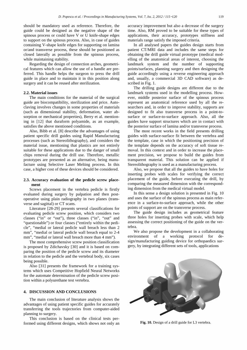
In this sense a design solution is presented in and uses the surface of the spinous process as main refeence in a surface-to-surface approach, while the other points of support are on the transverse process.
The guide design includes as geometrical feature three holes for inserting probes with scale, which helpassessing the correct positioning of the guide on the vetebra.
We also propose the development ienvironment of a working protocol for dsign/manufacturing guiding device for orthopaedics sugery, by integrating different sets of tools,
Fig. 10. Design of a drill guide for L3 vertebra
119
accuracy improvement but also a decrease of the surgery proved to be suitable for these types of
applications, their accuracy, prototypes stiffness and the imposed criteria.
In all analysed papers the guides design starts from patient CT/MRI data and includes the same steps for obtaining the drill guide virtual prototype (medical mod-elling of the anatomical areas of interest, choosing the
number of supporting planning surgery and then designing the
accordingly using a reverse engineering approach and, usually, a commercial 3D CAD software) as de-
designs are different due to the in the modelling process. How-
middle posterior surface of the spinous process anatomical reference used by all the re-
order to improve stability, supports are o transverse process in a point-to-
surface approach. Also, all the support structures which are in contact with
and/or transverse process. The most recent works in the field presents drilling
surface fit between the vertebra and the positioning precision of
the template depends on the accuracy of soft tissue re-n this context and in order to increase the place-
, we propose to build the guides from This solution can be applied if
Stereolithography is used as a manufacturing process. that all the guides to have holes for
th scales for verifying the correct , before executing the drill, by
comparing the measured dimension with the correspond-ing dimension from the medical virtual model.
In this sense a design solution is presented in Fig. 10 he surface of the spinous process as main refer-
surface approach, while the other points of support are on the transverse process.
The guide design includes as geometrical feature three holes for inserting probes with scale, which help assessing the correct positioning of the guide on the ver-
We also propose the development in a collaborating working protocol for de-
sign/manufacturing guiding device for orthopaedics sur-gery, by integrating different sets of tools, applications
Design of a drill guide for L3 vertebra.
120 D. Popescu et al. / Proceedings in Manufacturing Systems, Vol. 7, Iss. 2, 2012 / 115−120
and advanced medical modelling methods with CAD, CAE, CAM, Reverse Engineering (RE) and RM tech-niques. This way the exchange of medical and technical information is facilitated and a degree of automation is ensured to a process which otherwise has to be totally resumed for each patient/clinical case.
ACKNOWLEDGEMENTS: The work has been co-
funded by the Sectoral Operational Programme Human Resources Development 2007-2013 of the Romanian Ministry of Labour, Family and Social Protection through the Financial Agreement POSDRU/89/1.5/S/62557. REFERENCES
[1] I. Gibson, D. W. Rosen, B. Stucker, Additive Manufactur-ing Technologies: Rapid Prototyping to Direct Digital Manufacturing, Springer, 2009.
[2] F. Liou, Rapid Prototyping and Engineering Applications. A Toolbox for Prototype Development, CRC Press, Francis &Taylor Group, 2008.
[3] M.E. Hoque, Advanced Applications of Rapid Prototyping Technology in Modern Engineering, Intech, Croatia, 2011.
[4] J. Giannatsis, V. Dedoussis, Additive fabrication technolo-gies applied to medicine and health care: a review, Int J Adv Manuf Technology, vol. 40, no.1−2, 2007, pp.116−127.
[5] P.J. Bartolo, H.A. Almeida, Rezende, R.A., T. Laoui, B. B. Bidanda, Ch.8. Advanced Processes to Fabricate Scaffolds for Tissue Engineering in Virtual Prototyping & Bio Man-ufacturing in Medical Applications, Springer, 2008, pp. 149−170.
[6] L. H. Hsu, G. F. Huang, C. T. Lu, D. Y. Hong, S. H. Liu, The Development of a Rapid Prototyping Prosthetic Socket Coated with a Resin Layer for Transtibial Amputees, Prosthet Orthot Int, vol.34, no.1, 2010, pp. 37−45.
[7] T.M. Chu, D.G. Orton, S.J. Hollister, S.E. Feinberg, J.W. Halloran, Mechanical and in vivo performance of hy-droxyapatite implants with controlled architecture, Bio-materials vol. 22, 2002, pp. 1283−1293.
[8] Bibb, R., et al., Rapid manufacture of custom-fitting surgi-cal guides, Rapid Prototyping Journal, vol. 15, no. 5, 2009, pp. 346−354.
[9] Y.N. Vincent, J.H. DeClaire, K. R. Berend, B.C. Gulick, A.V. Lombardi, Improved Accuracy of Alignment With Patient-specific Positioning Guides Compared With Man-ual Instrumentation in TKA, Clinical Orthopaedics and Re-lated Research, vol. 470, no. 1, 2012, pp. 99−107.
[10] M. Kunz, et al., Computer-Assisted Hip Resurfacing Using Individualized Drill Templates, Journal of Arthroplasty, vol. 25, no. 4, pp. 600−606.
[11] K. Van Brussel, J. Vander Sloten, R. Van Audekercke, Medical image based design of an individualized surgical guide for pedicle screw insertion, Proceedings 18th An-nual Conference of the IEEE Engineering in Medicine and Biology Society: “Bridging Disciplines for Biomedicine, vol. 1, no. 1, 1997, pp. 225−226.
[12] E. Berry, M. Cuppone, S. Porada, Personalised image-based templates for intra-operative guidance, Proc Inst Mech Eng, vol. 219, no. 2, 2005, pp. 111−118.
[13] S. Porada, et al., Computer Aided Surgery with Lumbar Vertebral Drill-guides, Using Computer Aided Planning, Design and Visualisation, 2001, available online: http://events.cs.bham.ac.uk/miua2001/posters/porada.pdf.
[14] S. Lu et al., Rapid Prototyping drill guide template for lumbar pedicle screw placement, Chinese Journal of Traumatology, vol. 12, no. 3, 2009, pp. 171−177.
[15] T.C. Ryken et al. Engineering patient-specific drill tem-plates and bioabsorbable posterior cervical plates: a fea-sibility study, J Neurosurg Spine, vol. 10, 2009, pp. 129−132.
[16] K. Birnbaum, et al., Computer-assisted orthopedic surgery with individual templates and comparison to conventional operation method, Spine, vol. 26, no. 4, 2001, pp. 365−370.
[17] T. Yoo, 3D Informatics: A Research Program in High Performance Computing; A report to the Board of Scien-tific Counselors, May 2003, Lister Hill National Center for Biomedical Communications.
[18] J. Goffin, K. Van Brussel, K. Martens, J. Vander Sloten, R. Van Audekercke, M.H. Smet Three-dimensional computed tomography-based, personalized drill guide for posterior cervical stabilization at C1–2. Spine, vol. 26, 2001, pp. 1343−1347.
[19] T.C. Ryken, Image-based drill templates for cervical pedicle screw placement: Laboratory investigation, Neu-rosurg Spine, vol. 10, 2009, pp. 21−26.
[20] B.D. Owen, C.E. Christensen, J.M. Reinhardt, T.C. Ryken, Rapid prototype patient-specific drill template for cervical pedicle screw placement, Comput Aided Surg, vol. 12, 2007, pp. 303–308.
[21] S. Lu, et al., A novel computer-assisted drill guide tem-plate for placement of C2 laminar screws, Eur Spine J, vol. 18, 2009, pp. 1379−1385.
[22] S. Lu, et al. Efficacy and accuracy of a novel rapid proto-typing drill template for cervical pedicle screw placement, Computer-Aided Surgery, vol. 16, issue 5, 2011, pp. 240−248.
[23] T. Ma, Y.Q Xu, Y.B. Cheng, M.Y. Jiang, X.M. Xu, L.Xie, S.Lu, A novel computer-assisted drill guide template for thoracic pedicle screw placement: a cadaveric study, Arch Orthop Trauma Surg, vol. 132, 2012, pp. 65−72.
[24] J. Kashani, A surgical drill guide for pedicle screw place-ment, International Conference on Biomedical Engineering (ICoBE), 2012, pp. 305−307.
[25] F. Salako, C.E. Aubin, C. Fortin, H. Labelle, Development of patient-specific surgical templates, using rapid prototyping, for the fixation of pedicle screws, ITBM-RBM, vol. 24, 2003, pp. 199−205.
[26] J.M. Mac-Thiong, H. Labelle, M. Rooze, V. Feipel, C.E. Aubin, Evaluation of a transpedicular drill guide for pedicle screw placement in the thoracic spine. Eur Spine J vol. 12, 2003, pp. 542–547.
[27] H. Defino, Ideas and technical innovation: a guide for the aligned perforation of vertebral pedicles, European Spine Journal, vol. 11, no. 2, 2002, pp. 172−175.
[28] R. Xu, et al., Thoracic pedicle screw placement guided by computer tomographic measurements, J. Spinal Disorders, vol. 12, 1999, pp. 222−226.
[29] S.K. Mirza, al., Accuracy of Thoracic Vertebral Body Screw Placement Using Standard Fluoroscopy, Fluoro-scopic Image Guidance, and Computed Tomographic Im-age Guidance: A Cadaver Study, Spine, vol. 28, 2003, pp. 402−413.
[30] M. Zdichavsky, et al., Accuracy of pedicle screw place-ment in thoracic spine Fractures. Part I inter- and intra-observer reliability of the scoring system, Eur J Trauma, vol. 30, 2004, pp. 234−240.
[31] D. Popescu, C.Gh. Amza, D.F. Anania, Gh.Amza, D.T. Cicic, Intelligent x-ray based training system for pedicle screw placement in lumbar vertebrae, Academic Journal of Manufacturing Engineering, vol .9, no. 1, 2011, pp. 94−101.