design and simulation of new versions of tube launched uav
TRANSCRIPT

Design and Simulation of New Versions of Tube Launched UAV
Y. Zhou and A. M. Anvar
School of Mechanical Engineering, The University of Adelaide
Adelaide, South Australia, Australia Emails: [email protected]; [email protected]
Abstract: Currently, Unmanned Aerial Vehicles (UAVs) are widely used on exploring and monitoring the oceans. Such as a Tube Launched UAV (TLUAV), that may tightly pack into a water-resistant narrow tube and can be conveyed via an Autonomous Underwater Vehicle (AUV). After the TIUAV launched on the sea-surface, with having onboard automated, command, control, and navigation systems, it can easily reach to the high cruising-radius. There are several fully developed TLUAVs, such as ‘MAVERIC’ designed by Prioria Robotics Company, enlisting in a number of applications including with the United States Army. With the development of a large-scaled economically viable TLUAVs, they can support the exploration of the ocean resources, search and rescue missions, operational recognizance and surveillance missions, and so on.
The goal of this research was to compare the performance between different types of Tube launched UAV under different sea states with diverse wind directions, and further more to optimize a new version, which may achieve better performance. There are two new versions have been developed in this project, which are the unfurling-methods of structure of the flexible UAV wings. One version was inspired from the bat wings and umbrella’s pulley system respectively, and the idea of the other version comes from the process of the birds’ wings during takeoff procedure. The wings of both models can be opened automatically after the UAV launched from the tube-launcher by its control system, and can be locked and fixed when the wings are fully unfurled.
For the monitoring purpose, due to the advantages of low speed of the TLUAV and its stability on air, it can carry several small sensors including with a small real-time video camera, to be able to monitor a pre-specified part of the surface ocean. In this case, the unmanned air-robot is designed to perform with the cruise speed of 10 m/s. In addition, the new models designed and investigated within this research are compared versus the existing TLUAV models under different wind velocities and based on the sea states 0, 1 and 2, as well as various wind directions including with windward and crosswind conditions. Furthermore, in this research study, a comparison of the lift-force, drag-force and side-force of the TLUAV model by using the computational fluid dynamic (CFD) method is investigated. Moreover, the results were compared with the popular models including with the MAVERIC model and other civilian versions to show the differences and improvements.
Keywords: UAV, tube launched, sea state ,CFD
21st International Congress on Modelling and Simulation, Gold Coast, Australia, 29 Nov to 4 Dec 2015 www.mssanz.org.au/modsim2015
753
Y. Zhou and A. Anvar, Design and simulation of two new versions of Tube Launched UAV
1. INTRODUCTION
Currently, Unmanned Aerial Vehicles (UAV) are widely used in exploring and monitoring the surface of oceans, such as search and rescue missions, environmental study, security, etc. It was originally developed for the conflict situation, which is first happened between Austria and Italy on 1849. In the 20th century, with the development of the large-scaled exploitation of ocean resources, the UAVs have become more common in use of numerous civilian aspects, such as reconnaissance, and rescue mission scenarios. These UAVs normally launched from the open fields or mountains. For ocean exploration, there is a limited technology exist, which can allow the UAV launched from the surface of water (Basalt 2011).
In the late 20th century, a new idea, which is called Tube Launched UAVs (TLUAVs) have been promoted, which can solve the problem of launching the UAV from the surface of water. The TLUAV is a launching system that the UAV is packed within a narrow tube, which is carried by an Autonomous Underwater Vehicle (AUV), and would be unfurl its wings automatically after is being launched on the water surface.
Recently, there are several fully developed TLUAV models came to market, such as MAVERIC, which is recruited by the United States Army. These products achieved a high performance in most aspects (e.g.: payload, stability and controllability), but in terms of costs (as an example) the MAVERIC was built with a high cost (over 10 million dollars), (Prioria Robotic, 2010). In order to improve the technology to support maritime activities, there is a need to develop an economically reliable TLUAV for civilian applications.
This research study, investigates towards modeling and simulation of various tube launched UAVs, and analyzed their performances, including the lift-force, drag-force and side-force under different sea states, for each model. In addition, by comparing the result(s) of each model, the research was focused on optimization of the UAV model. More over several new models were compared with the MAVERIC model to find the differences as well as the advantages and disadvantages. According to the survey, using the low speed UAV(s), could be more viable for monitoring the ocean for civilian applications, the low speed UAVs can have more stability on air during real-time data-image gathering and transmission (Basalt 2011). In this case it is decided to conduct a research on the low speed TLUAV(s).
2. INVESTIGATION OF TUBE LAUNCHED UAV SYSTEM
This research study investigates towards the various types of the tube launching methods which is coming under two categories of Hard-wings and Soft-wings.
The Soft-wings models are design to manufacture by the soft and flexible materials, which can be bent and folded within a narrow tube. Hard-wings model(s) are design the way which can be packed into the tube-launcher by a flexible controlled mechanism. The characteristic of each type shown as below:
The advantages of the Soft-wings model are as follows:
• Light weight: the materials used to manufacture the wings are chosen from the light and flexible materials, such as Carbon Fiber Reinforced Plastic (CFRP).
• Easy control: Due to the property of the elastic material(s), the wings would be opened automatically after the UAV shooting out (launched) from the tube-launcher.
• Easy bending: the wings are easy to be bent and packed within the USV’s tube launcher.
The disadvantages of the Soft-wings model are as follows:
• High costs: the elastic materials should have the both property of elastic and strength, this types of materials are expensive to make.
• Soft-wings’ control system: in this design-model there is no control system to operate the main wings.
754
Y. Zhou and A. Anvar, Design and simulation of two new versions of Tube Launched UAV
The advantages of the Hard-wings model are as follows:
• Motor Drive: Motor Drive Speed L-shaped can operate under high speed. • Manufacturing the wings: the wings are easy to manufacture, via 3D printing. • Wings’ Controllable System: the main control system can be added within the wings.
The disadvantages of the Hard-wings model are as follows:
• Size of the wings’ edges: according to the initial fluid mechanic calculations, the width of the edge of each wing should be wider.
• Weight of the wings: due to the mechanism of the wings’ open system, the overall weight of this model of UAV would be higher than the Soft-wings UAV.
In summary, the main weakness of the Soft-wings model is the high cost of the wings material. Moreover, for Hard-wings model, because the weight of the unmanned air robot cannot be easily reduced, the improvement should be focused on the size of the aircraft.
3. OPTIMIZATION OF THE TUBE LAUNCHED UAV
This section presents the UAV optimization process. For improvement the focuses are on the enhancements of both Soft-wings and Hard-wings models respectively.
3.1. Optimization of the Soft-wings Model
According to the survey, it is fund that, the reason of the high cost of manufacturing of the Soft-wings model(s) is the high quality requirements for the wings materials (Prioria Robotic 2010). The wings should be opened automatically after the UAV launched, which means that the wings should be made by elastic material(s) that can open the wings in less than two seconds after leaving the tube. Moreover, due to the flying performance requirement, the strength of wings should be capable to support the UAV for flying on maritime air situations. Due to these requirement and using delicate and high costs materials to manufacture the Soft-wings, it is hard to reduce the costs, such as the MAVERIC model, which the cost of the design and manufacturing is over US$10 million.
In this investigation, to optimize the Soft-wings model, a special open mechanism was design and used instead of utilizing the elastic material(s) to reduce the costs.
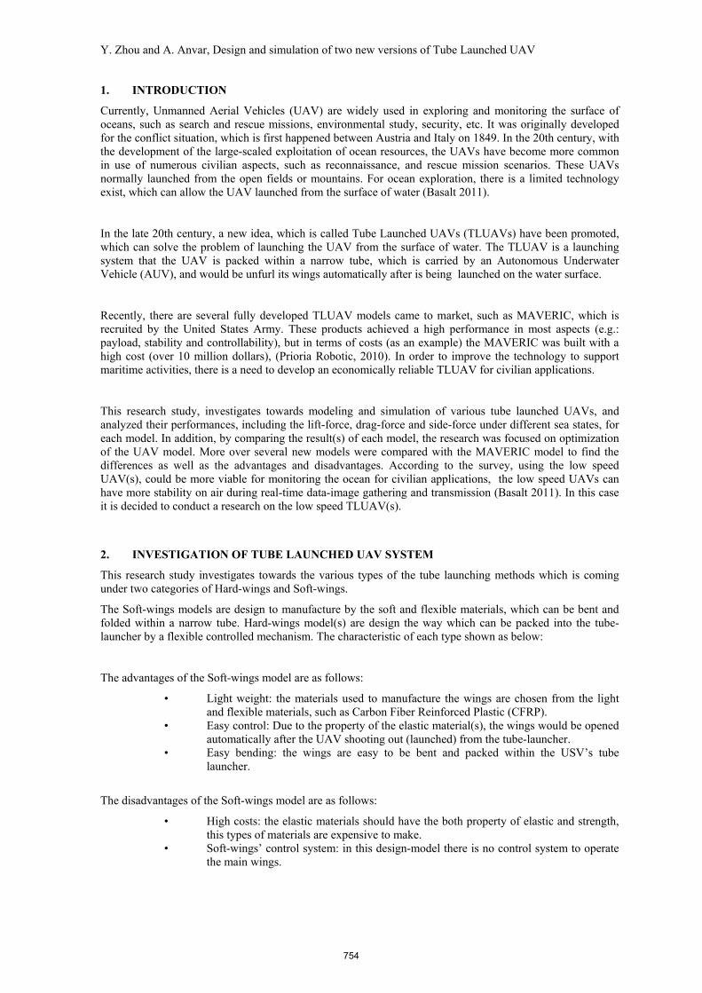
The mechanism shown in the Figure 1 includes several items, including with (A), a compress spring (the part at the center box), (B), two electromagnets (inside the part within the center box) and (C), a steel plate welded on the steel bar (the dark grey part which is connected to the spring (part A).
There is also an important component involved in this design that is the photo-resistor-relay system, which is included with a photo sensor and a relay module (see Figure 2). The relay can control the circuit according to the strength of the light. In this investigation, the light-strength is different between inside and outside of the tube, so that the relay can work as a switch for the wings to open. The operating principle in this system has two parts, which is the device 1 (electromagnets inside the spring)
Figure 1. The mechanism of the Soft-wings model.
755

Y. Zhou and A. Anvar, Design and simulation of two new versions of Tube Launched UAV
which would start working when there is no light in the surrounding, and device 2 (electromagnets not inside the spring) that would activated when the light is brightness. The system can also adjust the time delay of the circuit control, so that the wings would be opened as expected on time with no delay.
Figure 2. The operating principle of the photo-resistor-relay.
The Soft-wings operating functions are as following stages:
• Stage 1: the UAV has been packet in the tube, the electromagnet (part inside the spring) is powered on. So that the steel plate is fixed with the electromagnet inside the spring, and in this case, the system is closed and packed (see Figure 3, I & II (a)).
• Stage 2: the UAV shoot out, with the assistant of the photo resistor relay, the left electromagnet (the part inside the spring) is powered-off and the right electromagnet is powered-on, so the spring starts to push the steel plate to the right electromagnet. During this process, according to the mechanism, the framework of the wings would be opened (see Figure 3, I & II (b & c)).
[I] [II]
Figure 3. [I] from (a) to (d) frames & [II] from (a) to (d) frames with Soft-wings’ cover,
Steps of Soft-wings model open function
756
Y. Zhou and A. Anvar, Design and simulation of two new versions of Tube Launched UAV
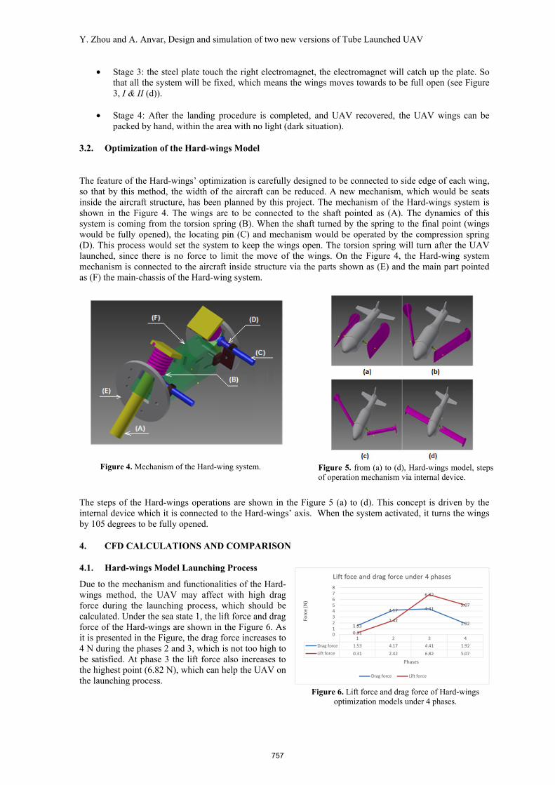
Figure 5. from (a) to (d), Hard-wings model, stepsof operation mechanism via internal device.
Figure 4. Mechanism of the Hard-wing system.
• Stage 3: the steel plate touch the right electromagnet, the electromagnet will catch up the plate. So that all the system will be fixed, which means the wings moves towards to be full open (see Figure 3, I & II (d)).
• Stage 4: After the landing procedure is completed, and UAV recovered, the UAV wings can be packed by hand, within the area with no light (dark situation).
3.2. Optimization of the Hard-wings Model
The feature of the Hard-wings’ optimization is carefully designed to be connected to side edge of each wing, so that by this method, the width of the aircraft can be reduced. A new mechanism, which would be seats inside the aircraft structure, has been planned by this project. The mechanism of the Hard-wings system is shown in the Figure 4. The wings are to be connected to the shaft pointed as (A). The dynamics of this system is coming from the torsion spring (B). When the shaft turned by the spring to the final point (wings would be fully opened), the locating pin (C) and mechanism would be operated by the compression spring (D). This process would set the system to keep the wings open. The torsion spring will turn after the UAV launched, since there is no force to limit the move of the wings. On the Figure 4, the Hard-wing system mechanism is connected to the aircraft inside structure via the parts shown as (E) and the main part pointed as (F) the main-chassis of the Hard-wing system.
The steps of the Hard-wings operations are shown in the Figure 5 (a) to (d). This concept is driven by the internal device which it is connected to the Hard-wings’ axis. When the system activated, it turns the wings by 105 degrees to be fully opened.
4. CFD CALCULATIONS AND COMPARISON
4.1. Hard-wings Model Launching Process
Due to the mechanism and functionalities of the Hard-wings method, the UAV may affect with high drag force during the launching process, which should be calculated. Under the sea state 1, the lift force and drag force of the Hard-wings are shown in the Figure 6. As it is presented in the Figure, the drag force increases to 4 N during the phases 2 and 3, which is not too high to be satisfied. At phase 3 the lift force also increases to the highest point (6.82 N), which can help the UAV on the launching process.
Figure 6. Lift force and drag force of Hard-wings optimization models under 4 phases.
757

Y. Zhou and A. Anvar, Design and simulation of two new versions of Tube Launched UAV
Figure 8. Drag force of each model under different sea state (windward).
5. CFD RESULTS COMPARISON
In this investigation, the CFD results of the two optimized models are compared with four previous models, which are Tape-wings, Four-wings, MAVERIC and CUTLASS models. The evaluation is focused on the wind-speed (based on Sea States 0, 1 and 2), and the Wind-direction which is nominated as Windward and crosswind.
Windward In this process the lift force of the above models compared, within the Sea States 0, 1 and 2 with considering the effect of the Windward and Wind direction. The result is shown in the Figure 7. According to the gradient in this Figure, Soft-wings models (i.e. new Soft-wings, MAVERIC and Type–wings models) achieved a better capability to carrying higher payloads than Hard-wings. Moreover, the new Soft-wings (optimized model) also presented a higher Lift-force capacity comparing with the MAVERIC UAV wings, which is encouraging results. The weakness of the Type-wings model appeared on the Figure showed the lift force is higher than two other Soft-wings models, which could be the shape of the wings that is not fully enhanced as the MAVERIC wings. In this investigation, the two Hard-wings models did not received a satisfactory results and that is due to the list capability to handle lift force. Ultimately, from the comparison of the new Soft-wings model’s lift-force is recognized as the most satisfying model comparing with the wings of the MAVERIC UAV.
Secondly, the drag force of the models has been also compared, which the result is shown in the Figure 8. According to the gradient appeared on the Figure, all of the models under this investigation, achieve closed results except the new Soft-wings model, which performed the highest lift force among the models. This means, that although the new Soft-wings model can cope with the higher payload, the energy efficiency would not be high, and that is due to the high drag force. As it shows on the Figure, it is noticeable that the wings of the MAVERIC UAV can handle the higher drag force.
Crosswind The similar situation exists with comparison of the lift force on different Sea States (0, 1 & 2) in the crosswind direction as shown in the Figure 9. As it appears in the Figure, with considering the effect of the crosswind on the MAVERIC wings and the new Soft-wings model, the MAVERIC can handle the highest lift force comparing with others models. However, in this process as it shows on the gradient results, the new soft-wings showed a higher lift force than four other soft wing models which is a positive result towards performance of this model.
The comparison of the drag force under crosswind is also similar to the windward. As it is appeared, the new Soft-wings model gets the highest drag force. The other models are almost closed to each other (as shown in the Figure 10).
Figure 7. Lift force of each model under different sea state (windward).
Figure 9. Lift force of each model under different sea state (crosswind).
758

Y. Zhou and A. Anvar, Design and simulation of two new versions of Tube Launched UAV
Figure 10. Drag force of each model under different sea state (crosswind).
Furthermore, According to the results presented on the Figure 11, the side force which is caused by the crosswind, may affect the stability of the UAV during the flying process. As shown in the figure, the side force of the two new optimized models is higher than the other models. It means, by enhancing the shape of the two new models, may improve their capabilities to handle the higher side-force. However, referring to the figure, as currently the value of the force is less than 3 (N) under the Sea state 2, so that, it may not affect much on the stabilities of the UAVs under this investigation.
6. CONCLUSIONS
During this research-study, several models have been built in Inventor, analysed, improved and investigated to achieve the most suitable optimized models. The flying performances of the models’ and their capabilities have been analyzed with using the ANSYS (CFD). Moreover, the lift, drag and side forces, of these models have been compared and analyzed based on the sea states 0, 1 and 2. Overall, in this research, the Hard-wings and Soft-wings models have been examined under the high speed operations and the outcomes of the investigation are achieved as follows:
• The Soft-wings model, satisfied flying under the low speed condition. • The Hard-wings model satisfied flying requirements under the state of high speed
situation. • The optimized Soft-wings model designed in this research-study with high
aerodynamics drag-force may be able to carry a higher payload compared with the MAVERIC UAV model.
ACKNOWLEDGEMENTS
The authors would like to acknowledge and thank the support of the Defence Science and Technology Organization in this project.
REFERENCES
Basalt (2011), “Lightweight Weapons for Autonomous Platforms”, http://defense-update.com/features/du-1-07/armedUAVs_5.htm
L-3 Unmanned Systems (2011), “The Tube Launched, Expendable UAS”, http://www2.l-3com.com/uas/pdfs/tech/Cutlass.pdf
Pake (2014),”A feasibility study of design, development and operation of Submersible Tube Launched UAV Robot”, Master Project 1580, School of Mechanical Engineering, The University of Adelaide.
Prioria Robotic (2010), “MAVERIC UAS”, http://www.prioria.com/
Figure 11. Side force of each model under different sea state (crosswind).
759