design and software architecture - mcmaster...
TRANSCRIPT

Ch. 4 1
Design and Software Architecture

Ch. 4 2
Outline • What is design • How can a system be decomposed into modules • What is a module’s interface • What are the main relationships among modules • Software design techniques and information
hiding • The UML collection of design notations • Design patterns • Architectural styles

Ch. 4 3
What is design? • Activity that provides structure to any artifact:
– Different domains: construction, mechanical systems, chemical systems, electrical systems
– Different aspects: system design, hardware design, and software design
• Decomposes system into parts, assigns responsibilities, ensures that parts fit together to achieve a global goal
• Design refers to both an activity and the result of the activity
Ch. 4 4
Two meanings of "design“ activity in our context
• Activity that acts as a bridge between requirements and the implementation of the software
• Activity that gives a structure to the artifact – Requirements specification document must be
designed
– must be given a structure that makes it easy to understand and evolve

Ch. 4 5
The software design activity • Defined as system decomposition into
modules
• Produces a Software Design Document – describes system decomposition into modules
• Often a software architecture is produced prior to a software design

Ch. 4 6
Software architecture • Shows gross structure and organization of the
system to be defined
• Its description includes description of: – Main components of a system – Rationale for decomposition into its components – Relationships among those components – Constraints that must be respected by any design
of the components
• Guides the development of the design

Ch. 4 7
Software architecture: an attempt to solve the problems of large systems
• Human’s inability in comprehending all the details of a project
• The lack of standard software design and development techniques
• Legacy systems maintenance and evolution
• Separation of Concerns, and high-level view of system
• Design patterns, design for reuse, architectural styles
• Software architecture recovery
Solution provided by Problems Software Architecture

Ch. 4 8
Software Architecture definitions
• A generally accepted definition:
“The structure of the components of a program/system, their interrelationships, and principles and guidelines governing
their design and evolution over time” [SEI 1994]
• However, software architecture is more than “components and connectors”, or “major elements of a system”. It is a collection of views, patterns, stakeholders, and roles [SEI].
• Therefore, Software architecture provides the necessary means to formalize and interpret the properties of a system.
Ch. 4 9
Software architecture terminology • Components: encapsulation of the system’s
computation – Filter, layer, client, etc.
• Connectors: encapsulation of interactions among components – RPC, event broadcast, pipe, etc.
• Styles: definition of components & connectors, their properties, and configuration constraints that apply to all instances of a family of closely related systems – Pipe/filter, implicit invocation, client/server, etc.

Ch. 4 10
Interface
Dependency
Component Diagram for ABM
• Meaningful naming for services
• Correct direction for the dependency arrows.

Ch. 4 11
See the brief guideline on how to design Component Diagram
and Statechart at the architectural level of a system���
in Lab 4 description

Ch. 4 12
Important Aspects of Software Architecture
• Architectural Styles
• Architectural views
• Architecture Description Languages
• Architectural Analysis and Evaluation
• Architecture Recovery

Ch. 4 13
Architectural Styles
Ch. 4 14
Sample Architectural Styles • Pipe and filter: UNIX shell • Client and server: distributed systems • Implicit invocation (Broker): CORBA, HP SoftBench • Layered: ISO/OSI reference model • Data repository (Blackboard): modern compilers, databases • Object-oriented: Aesop • Interpreter: programming languages • State transition: reactive systems • Main program and procedure: traditional systems • DSSA: avionics, C2, vehicle management
Ch. 4 15
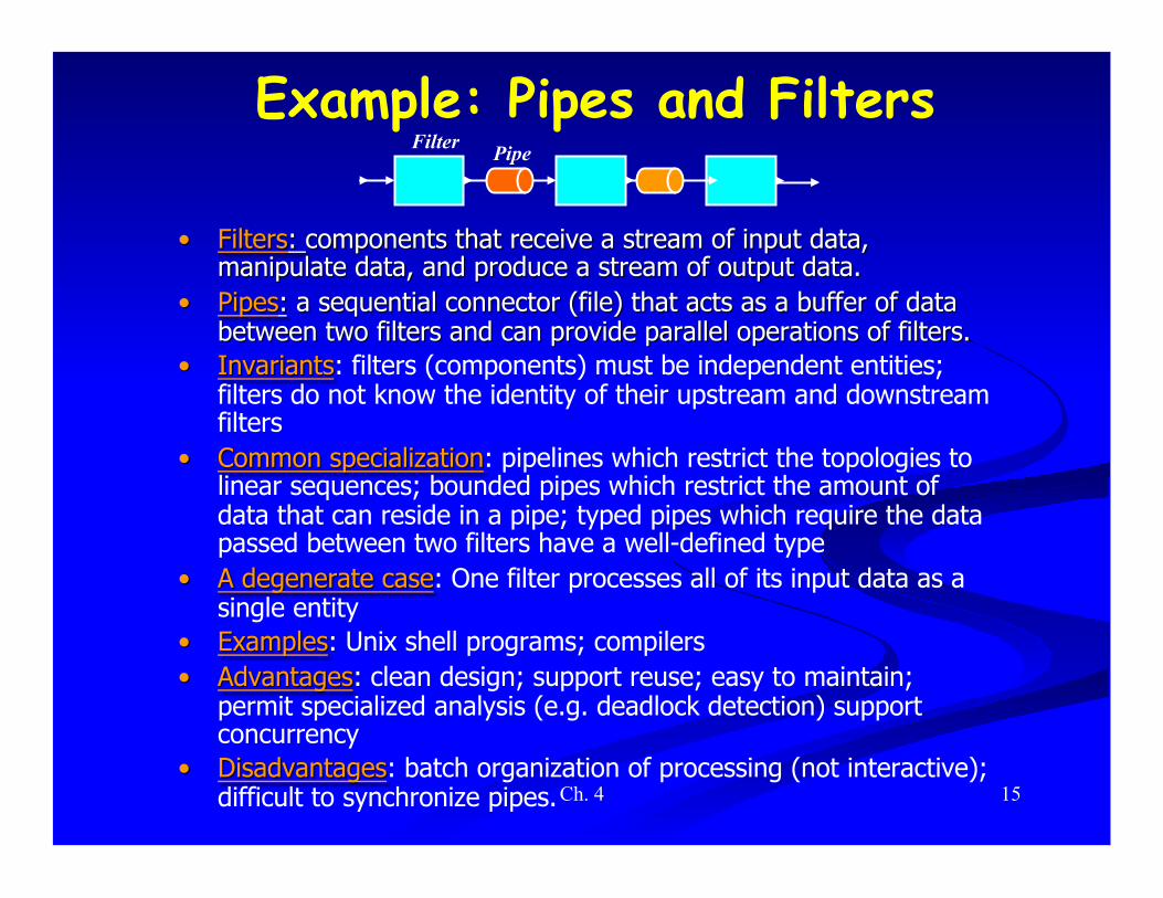
Example: Pipes and Filters Filter Pipe
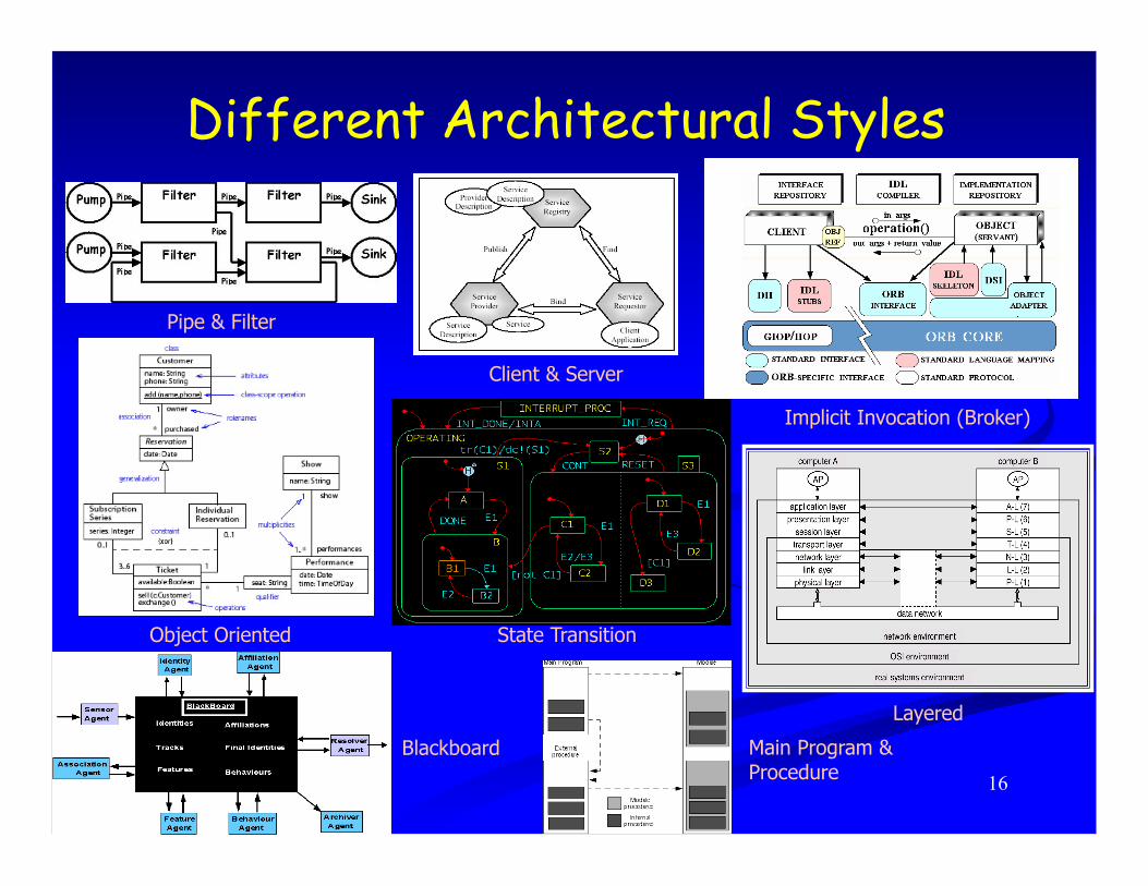
Different Architectural Styles
Ch. 4 16
Pipe & Filter
Implicit Invocation (Broker)
State Transition
Client & Server
Object Oriented
Main Program & Procedure
Layered
Blackboard

Ch. 4 17
Software Architecture Views

Ch. 4 18
• Architectural views assist engineers in understanding, developing, and communicating different aspects of a software system.
• Different groups of researchers have developed their own set of views
• Two important examples: 4+1 views and Zachman framework.
Software Architecture views

Ch. 4 19
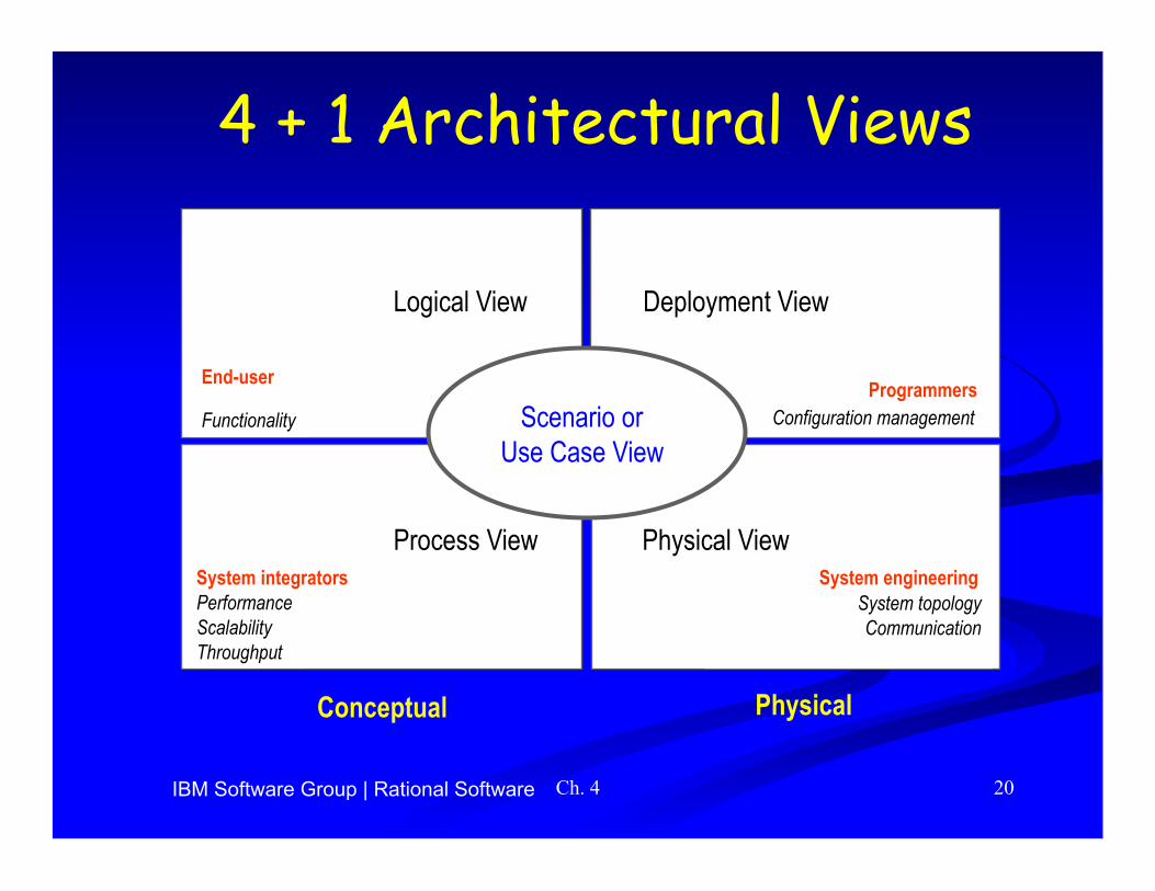
• 4+1 View Model 1) Logical: functional requirement
2) Process: concurrency, distribution of system services
3) Deployment: planning, monitoring, reuse
4) Physical: network topology
+1) Scenario: represents the sequence of system operations; it shows the relation among the elements of the 4 views: • Scenarios are represented by: object-interaction diagram, sequence
diagram, collaboration diagram, statecharts. • Sometimes referred to as: use-case, or work flow.
Software Architecture views 4+1 views
Ch. 4 20
4 + 1 Architectural Views
Logical View
End-user
Functionality
Deployment View
Programmers Configuration management
Process View
Performance Scalability Throughput
System integrators Physical View
System topology Communication
System engineering
Conceptual Physical
Scenario or Use Case View
IBM Software Group | Rational Software

Ch. 4 21
Scenario for telephone conversation in a PBX system
Figure shows a fragment of a scenario for the small PBX:
1. The controller of Joe’s phone detects and validate the transition from on-hook to off-hook and sends a message to wake up the corresponding terminal object.
2. The terminal allocates some resources, and tells the controller to emit some dial-tone. 3. The controller receives digits and transmits them to the terminal. 4. The terminal uses the numbering plan to analyze the digit flow. 5. When a valid sequence of digits has been entered, the terminal opens a conversation.

Ch. 4 22
Software Architecture views: Zachman’s framework (Views & Perspectives)
Zachman proposes a framework of views and perspectives that allows to map the knowledge about the system into non-overlapping representations provided by the framework.
Views categorize the knowledge about the system into manageable and understandable forms. They answer to questions on: What, How, Where
Views: Data view Function view Network view
Descriptive Entity-Relation-Entity Input-Process-Output Node-Line-Node model:
Question: What the software How the software Where the is made of? works? connections exist?
Concern: Material Functionality Location
Focus: Structure of data Data transformation Flow

Ch. 4 23
Zachman’s framework (views & perspectives)
• General scope: (Owner & business planer) – Description of gross estimation of the product’s features
• Owner (Owner): – Representation of owner’s desires from the final product
• Designer (architect): – Translation of owner’s representation to a technical plan
• Developer (contractor): – Translation of designer’s plan to a feasible plan
• Programmer (builder): – Actual production from a feasible plan
Perspectives: Each perspective is a system documentation that reflects the interests of a different stakeholder in software development.

Ch. 4 24
Framework Data view Function view Network view General scope
Owner’s perspective
Designer’s perspective
Developer’s perspective
Programmer’s perspective
(Ballpark)
(Contractor’s plan)
(Builder’s product)
(Architect’s plan)
List of entities important
to business
List of functions the business performs
List of locations the business operates
Entity-relation diagram
Function flow diagram
Logistic network
Data model Data flow diagram
Distributed system architecture
Data design Structure chart System architecture
Program Network architecture Data description

Ch. 4 25
Design Example:
• Order-Taking unit. • Assembling unit. • Preparation unit. • Inventory unit. • Management unit.
(MGR)
(INV)

Ch. 4 26
Restaurant system with mixture of different views

Ch. 4 27
Framework of different representations of restaurant sys.
Ch. 4 28
General Scope (Perspective)
Zachman’s Framework of Views and Perspectives

Ch. 4 29
Restaurant-menu, menu-items, orders, raw-materials, and recipes are the main data entities
• Each order consists of menu-items. • Menu-items are selected from the restaurant-
menu • Each menu-item consists of raw-materials
and the recipe
Fast-food restaurant system: • General Scope • Data view D1
Data View (General Scope)

Ch. 4 30
• Setting-up orders from restaurant-menu • Handling order payment • Distributing menu-items to be prepared • Assembling orders from the prepared menu-items • Keeping track of raw-material consumption • Setting-up different tables, prices, and recipes
Fast-food restaurant system: • General Scope • Function view F1
Function View (General Scope)

Ch. 4 31
Network View (General Scope)

Ch. 4 32
Owner’s Perspective
Zachman’s Framework of Views and Perspectives

E-R diagram of the Restaurant System
1 2
2
3
3
4
2 3 4
2
Restaurant-menu, menu-item (tables), order (tables), raw-material (table), and are the main data entities
• Each order consists of menu-items.
• Menu-items are selected from the restaurant-menu
• Each menu-item consists of raw-materials and the recipe

Ch. 4 34
Function View (Owner’s Perspective)
• Setting-up orders from restaurant-menu • Handling order payment • Distributing menu-items to be prepared • Assembling orders from the prepared menu-items • Keeping track of raw-material consumption • Setting-up different tables, prices, and recipes
NOT IN EXAM

Ch. 4 35
Network View (Owner’s Perspective)
NOT IN EXAM

Ch. 4 36
Aspects of Design

Ch. 4 37
Two important goals • Design for change (Parnas)
– designers tend to concentrate on current needs – special effort needed to anticipate likely changes
• Product families (Parnas) – think of the current system under design as a
member of a program family – Design the core part of a family of system

Ch. 4 38
Sample likely changes? (1) • Algorithms
– e.g., replace inefficient sorting algorithm with a more efficient one
• Change of data representation – e.g., from binary tree to a threaded tree (see
example) – ≈17% of maintenance costs attributed to data
representation changes (Lientz and Swanson, 1980)

Ch. 4 39
Example
Ch. 4 40
Sample likely changes? (2) • Change of underlying abstract machine
– new release of operating system – new optimizing compiler – new version of DBMS – …
• Change of peripheral devices
• Change of "social" environment – new tax regime – EURO vs national currency in EU
• Change due to development process – transform prototype into product

Ch. 4 41
Product families • Different versions of the same system
– e.g. a family of mobile phones • members of the family may differ in network
standards, end-user interaction languages, …
– e.g. a facility reservation system • for hotels: reserve rooms, restaurant,
conference space, …, equipment (video beamers, overhead projectors, …)
• for a university – many functionalities are similar, some are different
(e.g., facilities may be free of charge or not)

Ch. 4 42
Design goal for family
• Design the whole family as one system, not each individual member of the family separately

Ch. 4 43
Sequential completion: the wrong way
• Design first member of product family
• Modify existing software to get next member products

Ch. 4 44
Sequential completion: a graphical view
Requirements
1
2
3
Version 1
Version 1
Version 2 5
Requirements
1
2
3
4 6
7 Version 3
4
Requirements
1
2
3
Version 2 5
Version 1
4
intermediate design
final product

Ch. 4 45
How to do better • Anticipate definition of all family members
• Identify what is common to all family members, delay decisions that differentiate among different members
• We will learn how to manage change in design

Ch. 4 46
Module
• A well-defined component of a software system
• A part of a system that provides a set of services to other modules – Services are computational elements that
other modules may use

Ch. 4 47
Questions
• How to define the structure of a modular system?
• What are the desirable properties of that structure?

Ch. 4 48
Modules and relations
• Let S be a set of modules S = {M1, M2, . . ., Mn}
• A binary relation r on S is a subset of S x S that is r ⊂ S x S
• If Mi and Mj are in S, then: <Mi, Mj> ∈ r can be written as Mi r Mj

Ch. 4 49
Relations
• Transitive closure r+ of r Mi r+ Mj iff Mi r Mj or ∃ Mk in S s.t. Mi r Mk
and Mk r+ Mj
(We assume our relations to be irreflexive) • r is a hierarchy iff there are no two
elements Mi, Mj s.t. Mi r+ Mj ∧ Mj r+ Mi

Ch. 4 50
Relations • Relations can be represented as graphs • A hierarchy is a DAG (directed acyclic graph)
M1
M2M3
M4
M1,1 M1,2 M1,3
M1,2,1 M1,2,2
M1,2,1,1
M
M M
M M
M
1
2 3
4 5
6
a) b)
a graph
a DAG

Ch. 4 51
The USES relation • A uses B
– A requires the correct operation of B – A can access the services exported by B through
its interface – it is “statically” defined – A depends on B to provide its services
• example: A calls a routine exported by B
• A is a client of B; B is a server • In a modular system:
– |r| << n2 where n = |S| – High fan-in and low fan-out

Ch. 4 52
Interface
Dependency
Component Diagram for ABM
• Meaningful naming for services
• Correct direction for the dependency arrows.

Ch. 4 53
Desirable property • USES should be a hierarchy: e.g., Layered Style
• Hierarchy makes software easier to understand – we can proceed from leaf nodes (who do not use others)
upwards
• They make software easier to build
• They make software easier to test

Ch. 4 54
Hierarchy • Organizes the modular structure through
levels of abstraction
• Each level defines an abstract (virtual) machine for the next level (OS architecture) – level can be defined precisely
• Mi has level 0 if no Mj exists s.t. Mi r Mj • let k be the maximum level of all nodes Mj s.t. Mi r Mj.
Then Mi has level k+1

Ch. 4 55
IS_COMPONENT_OF • Used to describe a higher level module as constituted by
a number of lower level modules
• A IS_COMPONENT_OF B – B consists of several modules, of which one is A
• B COMPRISES A
• MS,i={Mk | Mk∈S ∧ Mk IS_COMPONENT_OF Mi} we say that MS,i IMPLEMENTS Mi

Ch. 4 56
A graphical view M 1
M M
M M M M M
2 4
5 6 7 8 9
M 3
M M M M M 5 6 7 8 9
M 2 M 3 M 4
M 1
(IS_COMPONENT_OF) (COMPRISES)
They are a hierarchy

Ch. 4 57
Product families
• Careful recording of (hierarchical) USES relation and IS_COMPONENT_OF supports design of program families

Ch. 4 58
Interface vs. implementation (1) • USES and IS_COMPONENT_OF partially describe an
architecture
• To understand the nature of USES, we need to know what a used module exports through its interface
• The client imports the resources that are exported by its servers
• Modules implement the exported resources
• Implementation is hidden to clients

Ch. 4 59
Interface vs. implementation (2) • Clear distinction between interface and
implementation is a key design principle
• Supports separation of concerns – clients care about resources exported from servers – servers care about implementation
• Interface acts as a contract between a module and its clients

Ch. 4 60
Interface vs. implementation (3) interface is like the tip of the iceberg

Ch. 4 61
Information hiding • Basis for design (i.e. module decomposition)
• Implementation secrets are hidden to clients
• They can be changed freely if the change does not affect the interface
• Golden design principle – INFORMATION HIDING
• Try to encapsulate changeable design decisions as implementation secrets within module implementations

Ch. 4 62
How to design module interfaces? • Example: design of an interpreter for
language MINI – We introduce a SYMBOL_TABLE module
• provides operations to – CREATE an entry for a new variable – GET the value associated with a variable – PUT a new value for a given variable
– the module hides the internal data structure of the symbol table
– the data structure may freely change without affecting clients

Ch. 4 63
Interface design
• Interface should not reveal what we expect may change later
• It should not reveal unnecessary details
• Interface acts as a firewall preventing access to hidden parts

Ch. 4 64
Prototyping
• Once an interface is defined, implementation can be done – first quickly but inefficiently – then progressively turned into the final
version
• Initial version acts as a prototype that evolves into the final product

Ch. 4 65
More on likely changes an example
• Policies may be separated from mechanisms
• Mechanism (technique, method) – ability to suspend and resume tasks in a concurrent
system
• Policy (strategy, scheduling, protocol) – how do we select the next task to resume?
» different scheduling policies are available » they may be hidden to clients » they can be encapsulated as module secrets

Ch. 4 66
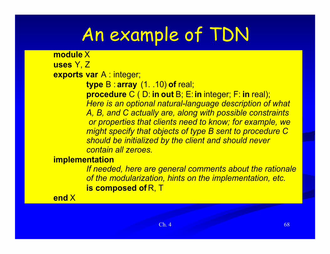
Design notations • Notations allow designs to be described precisely
• They can be textual or graphic
• We illustrate two sample notations – TDN (Textual Design Notation) – GDN (Graphical Design Notation)
• We discuss the notations provided by UML

Ch. 4 67
TDN & GDN • Illustrate how a notation may help in
documenting design
• Illustrate what a generic notation may look like
• Are representative of many proposed notations
• TDN inherits from modern languages, like Java, Ada, …
Ch. 4 68
An example of TDN module Xuses Y, Zexports var A : integer;
type B : array (1. .10) of real;procedure C ( D: in out B; E: in integer; F: in real);Here is an optional natural-language description of whatA, B, and C actually are, along with possible constraints or properties that clients need to know; for example, wemight specify that objects of type B sent to procedure Cshould be initialized by the client and should nevercontain all zeroes.
implementationIf needed, here are general comments about the rationaleof the modularization, hints on the implementation, etc.is composed of R, T
end X

Ch. 4 69
Comments in TDN • May be used to specify the protocol to be
followed by the clients so that exported services are correctly provided.
• Examples of protocols: – A certain operation which does the initialization of
the module should be called before any other operation
– An insert operation cannot be called if the table is full

Ch. 4 70
Example (cont.) module R uses Y exports var K : record . . . end;
type B : array (1. .10) of real;procedure C (D: in out B; E: in integer; F: in real);
implementation...
end R
module T uses Y, Z, R exports var A : integer;implementation
.
.
.end T
Ch. 4 71
Benefits • Notation helps describe a design precisely
• Design can be assessed for consistency – having defined module X, modules R and T must
be defined eventually • if not incompleteness
– R, T replace X • either one or both must use Y, Z
Ch. 4 72
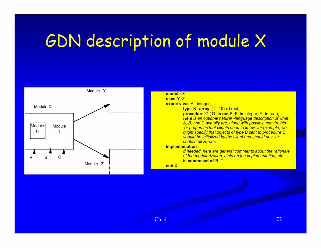
GDN description of module X
X
Y
Z A B
R T Module Module
Module
Module
Module
C
module X uses Y, Z exports var A : integer;
type B : array (1. .10) of real; procedure C ( D: in out B; E: in integer; F: in real); Here is an optional natural -language description of what A, B, and C actually are, along with possible constraints or properties that clients need to know; for example, we might specify that objects of type B sent to procedure C should be initialized by the client and should nev er contain all zeroes.
implementation If needed, here are general comments about the rationale of the modularization, hints on the implementation, etc. is composed of R, T
end X

Ch. 4 73
X's decomposition
module R uses Y exports var K : record . . . end;
type B : array (1. .10) of real;procedure C (D: in out B; E: in integer; F: in real);
implementation...
end R
module T uses Y, Z, R exports var A : integer;implementation
.
.
.end T
module X uses Y, Z exports var A : integer;
type B : array (1. .10) of real; procedure C ( D: in out B; E: in integer; F: in real); Here is an optional natural -language description of what A, B, and C actually are, along with possible constraints or properties that clients need to know; for example, we might specify that objects of type B sent to procedure C should be initialized by the client and should nev er contain all zeroes.
implementation If needed, here are general comments about the rationale of the modularization, hints on the implementation, etc. is composed of R, T
end X
Ch. 4 74
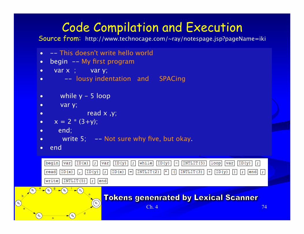
Code Compilation and Execution Source from: http://www.technocage.com/~ray/notespage.jsp?pageName=iki
• -- This doesn't write hello world • begin -- My first program • var x ; var y; • -- lousy indentation and SPACing
• while y - 5 loop • var y; • read x ,y; • x = 2 * (3+y); • end; • write 5; -- Not sure why five, but okay. • end
q
q q q q
q q
q
b
e g i
n
e
nd
0
1 2 3 4
5 6
f

Ch. 4 75
Code Compilation and Execution … 1. Generate Tokens
2. Use grammar to parse Tokens (don’t panic!)
3. Generate Syntax Tree From Tokens

Ch. 4 76
Code Compilation and Execution ….
3. Generate Syntax Tree From Tokens
5. Traverse tree To generate Assembly Program
6. Generate Machine Language Code for CPU
Assembler Program
7. Execute Machine Language On the computer
LD A, 4EH MOV B, A LD C, (addrs) ADD A, B, C LD (addrs+4), A
4. Attach Assembly Code

Ch. 4 77
Example: a compiler

Ch. 4 78
Other modules module MAIN uses ANALYZER, CODE_GENERATOR exports procedure MINI (PROG: in file of char;
CODE: out file of char); … end MAIN
module ANALYZER uses SYMBOL_TABLE, ABSTRACT_TREE_HANDLER exports procedure ANALYZE (SOURCE: in file of char);
SOURCE is analyzed; an abstract tree is produced by using the services provided by the tree handler, and recognized entities, with their attributes, are stored in the symbol table. ...
end ANALYZER
• -- This doesn't write hello world • begin -- My first program • var x ; var y; • -- lousy indentation and
SPACing
• while y - 5 loop • var y; • read x ,y; • x = 2 * (3+y); • end; • write 5; -- Not sure why five,
but okay. • end
Ch. 4 79
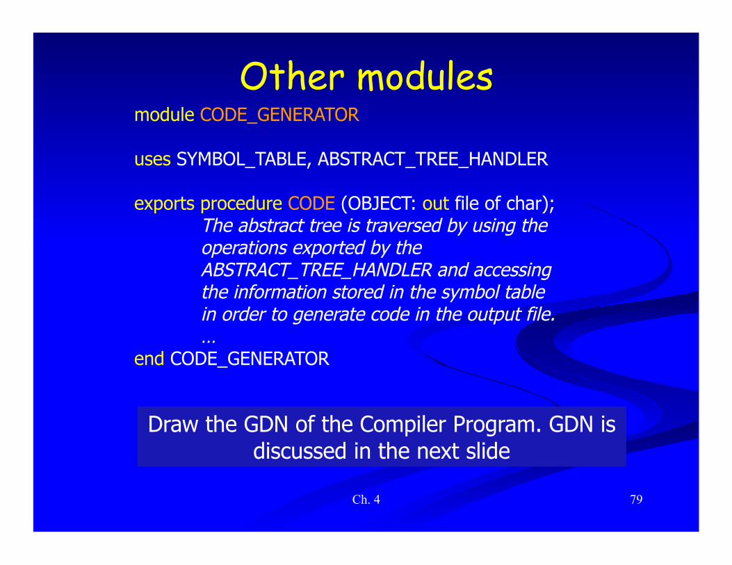
Other modules module CODE_GENERATOR
uses SYMBOL_TABLE, ABSTRACT_TREE_HANDLER
exports procedure CODE (OBJECT: out file of char); The abstract tree is traversed by using the operations exported by the ABSTRACT_TREE_HANDLER and accessing the information stored in the symbol table in order to generate code in the output file. …
end CODE_GENERATOR
Draw the GDN of the Compiler Program. GDN is discussed in the next slide

Ch. 4 80
Component Diagram: Compiler

Ch. 4 81
Example of Software Architecture http://www.turing.toronto.edu/~brewste/bkshelf/
NOT IN EXAM

Ch. 4 82
Usage of relations in Software Engineering: Architecture of Apache
S1
S2
S3
S4
S5
Rest-of-sys
Modularity Principle: Decomposing a system based on Low-coupling & High-cohesion
Color-coded Links represent the level of dependency of a file to another file
NOT IN EXAM

Ch. 4 83
Representing the architecture using
graph visualizer
(Rigi)
S1-S4 S2
rest-of-sys
S5 S3
File-level analysis
Function-level analysis
• Different types of links between boxes: – Association-links – Entity-usage links
• Association-links with different strengths to simplify the view
• Viewing the locus of interaction among entities to evaluate the recovery process
• Insight into the system before starting the recovery
• Manual recovery
NOT IN EXAM

Ch. 4 84
Categories of modules
• Functional modules – traditional form of modularization
– provide a procedural abstraction
– encapsulate an algorithm • e.g. sorting module, fast Fourier transform
module, …

Ch. 4 85
Categories of modules (cont.) • Libraries
– a group of related procedural abstractions • e.g., mathematical libraries
– implemented by routines of programming languages
• Common pools of data – data shared by different modules
• e.g., configuration constants – the COMMON FORTRAN construct
Ch. 4 86
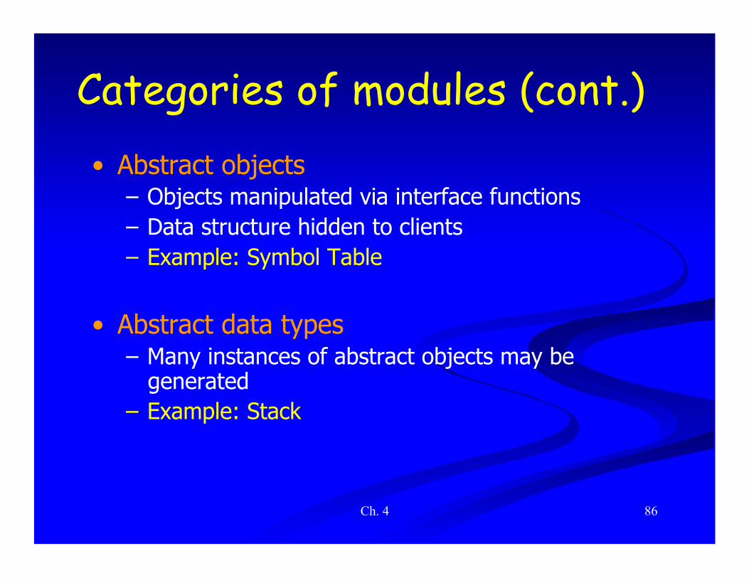
Categories of modules (cont.) • Abstract objects
– Objects manipulated via interface functions – Data structure hidden to clients – Example: Symbol Table
• Abstract data types – Many instances of abstract objects may be
generated – Example: Stack
Ch. 4 87
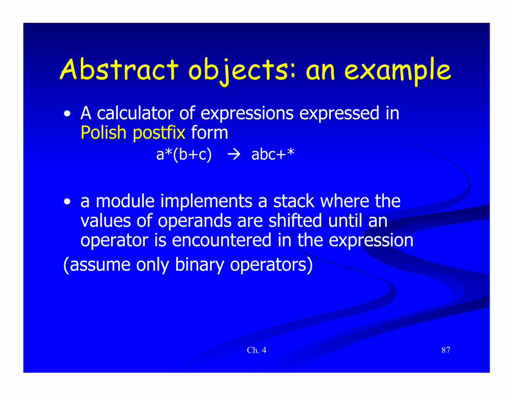
Abstract objects: an example • A calculator of expressions expressed in
Polish postfix form a*(b+c) abc+*
• a module implements a stack where the values of operands are shifted until an operator is encountered in the expression
(assume only binary operators)

Ch. 4 88
Example (cont.)
"exports: procedure PUSH (VAL: in integer); procedure POP_2 (VAL1, VAL2: out integer);
Interface of the abstract object STACK
Ch. 4 89
Design assessment
• How does the design anticipate change in type of expressions to be evaluated? – e.g., it does not adapt to unary operators

Ch. 4 90
module STACK_HANDLER exports
type STACK = ?; This is an abstract data -type module; the data structure is a secret hidden in the implementation part. procedure PUSH (S: in out STACK ; VAL: in integer); procedure POP (S: in out STACK ; VAL: out integer); function EMPTY (S: in STACK) : BOOLEAN; . . .
end STACK_HANDLER
Abstract data types (ADTs) • A stack ADT allows to have more than
one instance of a stack module indicates that details of the data structure are hidden from the clients

ADTs • An ADT module is a module that exports a type, along with the
operations needed to access and manipulate objects of that type.
• An ADT hides the representation of the type and the algorithms used in the operations. The details of the type is dealt with in the implementation of the ADT.
• Correspond to Java and C++ classes
• Concept may also be implemented by Ada private types and Modula-2 opaque types
• May add notational details to specify if certain built-in operations are available by default on instance objects of the ADT – e.g., type A_TYPE: ? (:=, =) indicates that assignment and equality check
are available

Ch. 4 92
An example: simulation of a gas station
module FIFO_CARS uses CARS exports
type QUEUE : ? ; procedure ENQUEUE (Q: in out QUEUE ; C: in CARS); procedure DEQUEUE (Q: in out QUEUE ; C: out CARS); function IS_EMPTY (Q: in QUEUE) : BOOLEAN; function LENGTH (Q: in QUEUE) : NATURAL; procedure MERGE (Q1, Q2 : in QUEUE ; Q : out QUEUE);
This is an abstract data-type module representing queues of cars, handled in a strict FIFO way; queues are not assignable or checkable for equality, since “:=” and “=” are not exported. …
end FIFO_CARS Module GAS-STATION uses FIFO_CARS gasoline_1, gasoline_2, gasoline_3: QUEUE car_wash: QUEUE; that_car: CARS; ENQUEUE (car_wash, that_car); MERGE (gasoline_1, gasoline_2, gasoline_3); end GAS_STATION

Ch. 4 93
Example of Modular Programming Using C
DEFINITION MODULE foo EXPORT list of functions and data declarations of exported functions and data
END foo
IMPLEMENTATION MODULE foo IMPORT list of modules used ... code ...
END foo
Modular Programming in CBy John R. Hayes, Courtesy of Embedded Systems ProgrammingNov 30 2001 (8:24 AM)URL: http://www.embedded.com/showArticle.jhtml?articleID=9900399
NOT IN EXAM

Ch. 4 94
/* foo.c */ /* Import needed interfaces: */ #include "x.h" #include "y.h"
/* Implements this interface; used for compiler checks: */ #include "foo.h"
int var1; static int var2;
void Fun1(int *p) { ... } static void Fun2(void) { ... }
Listing 1: foo.c (implementation)
NOT IN EXAM

Ch. 4 95
Listing 2: foo.h (interface) /* foo.h */ #define var1 Foo_var1 /* prefixing function name with module name */ #define Fun1 FooFun1
extern int var1; extern void Fun1(int *);
NOT IN EXAM
Ch. 4 96
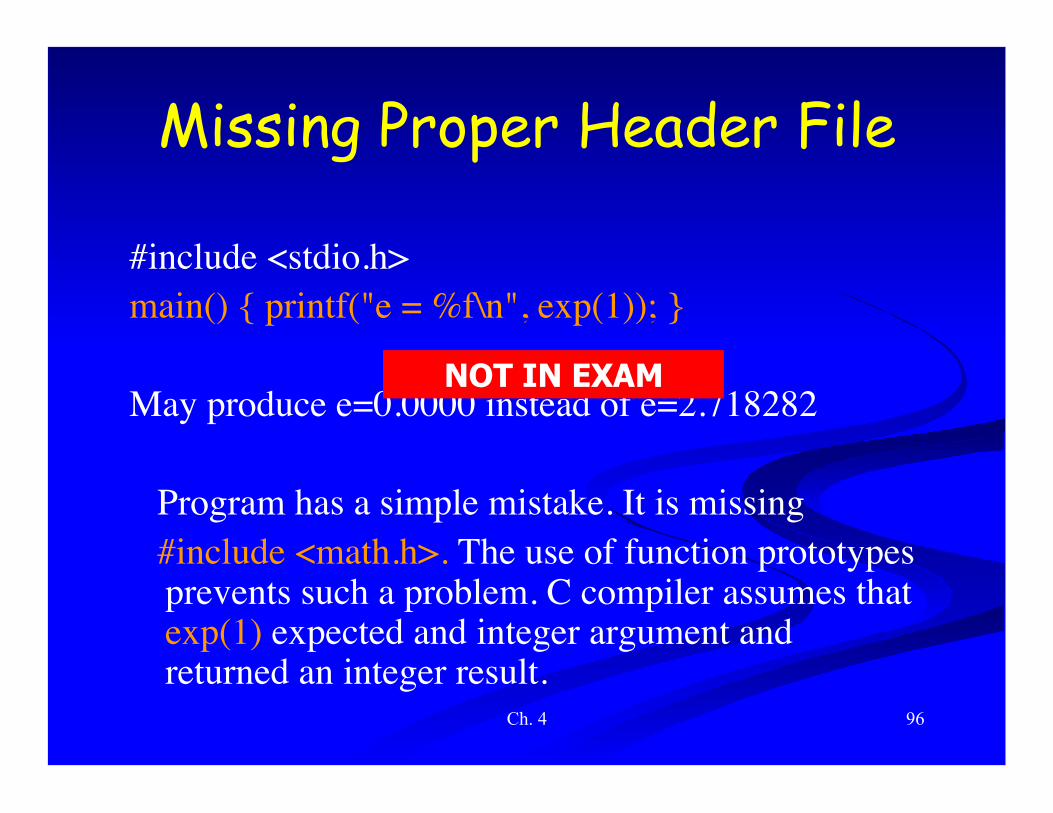
Missing Proper Header File
#include <stdio.h> main() { printf("e = %f\n", exp(1)); }
May produce e=0.0000 instead of e=2.718282
Program has a simple mistake. It is missing #include <math.h>. The use of function prototypes
prevents such a problem. C compiler assumes that exp(1) expected and integer argument and returned an integer result.
NOT IN EXAM

Ch. 4 97
Listing 3: client.c (implementation) /* client.c */ /* Import needed interfaces: */ #include "z.h"
/* Implements this interface: */ #include "client.h" static void ClientFun(void) { int z; ... Fun1(z); ...
} An integer passed to Fun1 instead of pointer to integer. #include “foo.h” is missing. Client.c will compile but linker Can not find Fun1 and will send an error message
NOT IN EXAM
Ch. 4 98
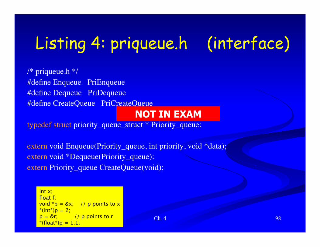
Listing 4: priqueue.h (interface) /* priqueue.h */ #define Enqueue PriEnqueue #define Dequeue PriDequeue #define CreateQueue PriCreateQueue
typedef struct priority_queue_struct * Priority_queue;
extern void Enqueue(Priority_queue, int priority, void *data); extern void *Dequeue(Priority_queue); extern Priority_queue CreateQueue(void);
int x; float f; void *p = &x; // p points to x *(int*)p = 2; p = &r; // p points to r *(float*)p = 1.1;
NOT IN EXAM

Ch. 4 99
• Modular programming consists of separating implementation from interface and hiding information in the implementation.
• In C this is achieved by placing the interface definition in a header file and the implementation in a source file.
• Disciplined use of static is used to hide implementation details. The interface definition forms the link between a module and its clients.
• The module includes its own interface definition to confirm that it implements the advertised interface; a client module imports/includes the interface definition to verify that it is using the interface correctly.
• Put the constant definitions and data structure declarations in the header for inclusion by its corresponding C source file. Now, if a constant or data structure is only used by one source file, place them in that source file. If a constant or data type is used throughout an application, they belong in a traditional header file.
NOT IN EXAM