design and testing of a concrete safety barrier for use on
TRANSCRIPT

University of Nebraska - LincolnDigitalCommons@University of Nebraska - Lincoln
Civil Engineering Faculty Publications Civil Engineering
2013
Design and Testing of a Concrete Safety Barrier forUse on a Temporary FRP Composite Bridge DeckMario MongiardiniUniversity of Nebraska - Lincoln, [email protected]
Ronald K. FallerUniversity of Nebraska - Lincoln, [email protected]
John D. ReidUniversity of Nebraska - Lincoln, [email protected]
Dave MeggersKansas Department of Transportation, [email protected]
Moni G. El-AasarBG Consultants Engineers, Architects & Surveyors, [email protected]
See next page for additional authors
Follow this and additional works at: http://digitalcommons.unl.edu/civilengfacpub
This Article is brought to you for free and open access by the Civil Engineering at DigitalCommons@University of Nebraska - Lincoln. It has beenaccepted for inclusion in Civil Engineering Faculty Publications by an authorized administrator of DigitalCommons@University of Nebraska - Lincoln.
Mongiardini, Mario; Faller, Ronald K.; Reid, John D.; Meggers, Dave; El-Aasar, Moni G.; and Plunkett, Jerry D., "Design and Testingof a Concrete Safety Barrier for Use on a Temporary FRP Composite Bridge Deck" (2013). Civil Engineering Faculty Publications. 125.http://digitalcommons.unl.edu/civilengfacpub/125

AuthorsMario Mongiardini, Ronald K. Faller, John D. Reid, Dave Meggers, Moni G. El-Aasar, and Jerry D. Plunkett
This article is available at DigitalCommons@University of Nebraska - Lincoln: http://digitalcommons.unl.edu/civilengfacpub/125
Mongiardini et al. , Journal of Bridge Engineering 18 (2013) 1
Published in Journal of Bridge Engineering 18:11 (2013), pp. 1198–1208.doi: 10.1061/(ASCE)BE.1943-5592.0000407Copyright © 2013 American Society of Civil Engineers. Used by permission. Submitted February 1, 2012, approved July 12, 2012, published online October 15, 2013.
Design and Testing of a Concrete Safety Barrier for Use on a Temporary FRP
Composite Bridge Deck
Mario Mongiardini,1 Ronald K. Faller, P.E., M.ASCE,2 John D. Reid,3 Dave Meggers, P.E.,4
Moni G. El-Aasar, P.E., F.ASCE,5 and Jerry D. Plunkett6
1 Postdoctoral Research Engineer, Midwest Roadside Safety Facility, Univ. of Nebraska-Lincoln, Lincoln, NE 68588 (corresponding author), email [email protected]
2 Research Professor, Midwest Roadside Safety Facility, Univ. of Nebraska–Lincoln, Lincoln, NE 68588, email [email protected]
3 Professor, Dept. of Mechanical and Materials Engineering, Univ. of Nebraska-Lincoln, Lincoln, NE 68588, email [email protected]
4 Research Development Engineer, Kansas Dept. of Transportation, 700 SW Harrison St., Topeka, KS 66603, email [email protected]
5 Vice President, BG Consultants Engineers, Architects & Surveyors, 4806 Vue Du Lac Pl., Manhattan, KS 66503, email [email protected]
6 President, Kansas Structural Composites, 553 S Front St., Russell, KS 67665, email [email protected]
AbstractFiber-reinforced polymer (FRP) composite materials can be used for the fabrica-tion of lightweight, corrosion-resistant honeycomb sandwich panels, representing a convenient and economical alternative to traditional steel RC for bridge decks. Composite panels are particularly advantageous for the construction of temporary bridge structures in terms of both ease of construction and reusability of panels. Although FRP sandwich panels have been considered for the construction of bridge decks, no barrier system has been developed and crash tested for use with this spe-cific type of deck. The objective of this research project was to develop a crashwor-thy concrete barrier system for use with temporary FRP composite bridge decks. Upon failure of a full-scale crash test with a New Jersey concrete safety shape bar-rier, an accurate analysis of the potential problems led to a series of design modifi-cations to the barrier as well as to the attachment between the composite deck and both the bridge structure and the barrier. The second design, which used a vertical-faced barrier, was successfully crash tested according to Test-Level 3 impact safety standards set forth in the AASHTO Manual for Assessing Safety Hardware (MASH).
Keywords: Safety, Barriers, Concrete, Fiber-reinforced polymer, Bridge decks
digitalcommons.unl.edu
Mongiardini et al. , Journal of Bridge Engineering 18 (2013) 2
Introduction
In recent years, fiber-reinforced polymer (FRP) composite materials have been used for the fabrication of lightweight, corrosion-resistant, honeycomb sandwich panels. In many engineering applications, these composite panels represent a convenient and economical alternative to structures made of traditional materials. In bridge engineering, FRP composite panels have been considered an advantageous alternative to traditional steel RC decks (Tang and Podolny 1998), thanks to their extreme weight reduction (up to 85%), increased resistance to corro-sion, longevity, and environmentally friendly impact (Cheng and Karb-hari 2006). Furthermore, the use of FRP decks in bridge construction has been found to reduce construction and repair time, because deck panels are fabricated off-site and installed at the bridge site in a timely manner. In addition to their improved performance, such as limited deflection, elevated fatigue resistance, and corrosion resistance, FRP composite decks provide an efficient solution for reducing the often high costs supported by road users from the disruption caused by long construction or maintenance periods. In particular, thanks to their ease of transportation and faster installation with respect to tradi-tional RC counterparts, FRP decks have also been considered for the construction of temporary bridges. In these cases, their longevity and corrosion resistance allows composite panels to be used several times for different temporary bridges, thus limiting the construction costs of temporary structures.
Although previous research demonstrated that the static capac-ity provided by a connection between a concrete barrier and an FRP bridge deck subassembly is comparable to that provided by a tradi-tional steel RC deck (Zhao et al. 2004), no bridge railing system has yet been developed and full-scale crash tested for use with a compos-ite deck. Further, in the prior mentioned research, a permanent con-crete barrier was cast in place onto a composite deck with primary steel reinforcement penetrating the FRP deck.
In this research, the objective was to develop a connection between a temporary concrete bridge railing and an FRP composite deck. In particular, a dismountable and reusable connection between the con-crete rail and the deck was required. A concrete railing system for attachment to an FRP temporary bridge deck was developed and its safety performance was investigated. A first design was unsuccessfully tested according to Test Level 3 (TL-3) impact conditions set forth in

Mongiardini et al. , Journal of Bridge Engineering 18 (2013) 3
National Cooperative Highway Research Program (NCHRP) Report No. 350 (Ross et al. 1993). Upon failure of the full-scale crash test with this initial design, an investigation and analysis of the potential problems was carried out, leading to a series of modifications to the barrier as well as the attachment of the composite deck to the bridge structure and the barrier. The second railing design, which used a vertical-faced geometry, was successfully tested according to TL-3 impact conditions defined in the newer AASHTO Manual for Assessing Safety Hardware (MASH 2009) impact safety standards.
Bridge Deck and Test Conditions
To test the bridge barrier designs under real-world conditions, a full-size bridge structure with an FRP deck system was constructed. Details of the bridge deck and testing conditions are provided in the following.
Testing Deck The FRP bridge deck was mounted over a structure composed of two steel girders supported by two simulated RC piers and a simple sup-port at each of the three midspans (Fig. 1). A bridge abutment was located at each end of the bridge structure.
The FRP bridge deck panels were sandwich structures with a hon-eycomb core. The outer surfaces were fabricated using a 13-mm (0.5-in) thick layer with 40% fiberglass and 60% polyester resin. The honeycomb core consisted of alternating flat and corrugated layers, as shown in Fig. 2. The flat FRP elements were 2.3-mm (0.09-in.) thick, while the corrugated layers had a 51-mm (2-in.) amplitude and a wavelength of 101.6 mm (4.0 in.). The core height was 178 mm (7 in.). The panel edges and closeouts were configured with 3.0-mm (0.12-in.) thick FRP elements and wet layups of 102–152 mm (4–6 in.) overlapping on the primary surfaces. The composite decks were manufactured according to a fiber architecture created by Kansas Structural Composites, Inc., Russell, Kansas (now Missouri Struc-tural Composites, St. Louis, Missouri), in combination with a polyes-ter matrix. In this architecture, three types of layers (randomly dis-tributed chopped strands and unidirectional and bidirectional-ori-ented fibers) were combined. Each of the three fiber distribution pat-terns was characterized by a constant 40% weight content of fiber-glass. This architecture guaranteed an equivalent isotropic compres-sion strength of the deck panels.

Mongiardini et al. , Journal of Bridge Engineering 18 (2013) 4
Each panel measured 4.40 m long x 2.40 m wide x 203 mm thick (14 ft 5 in x 7 ft 11.5 in 8 in.) and was to be placed transversely across the longitudinal steel bridge girders. The simulated bridge deck that was used for the full-scale crash-testing program consisted of 11 pan-els, for a total length of approximately 26.70m (87 ft 6.5 in.).
Fig. 1. Full-scale bridge structure used to support FRP composite deck
Fig. 2. FRP composite panel and detail of honeycomb core

Mongiardini et al. , Journal of Bridge Engineering 18 (2013) 5
The panel-to-girder connection was modified after the failure of the first crash test with the initial barrier system. Details of the deck attachment to the bridge support beams for each specific crash-tested design are given in subsequent sections of the paper. For testing pur-poses, single nuts were used to tighten the bolted connection between the barrier and the deck as well as between the deck panels and the girders. In real-world applications, the use of double nuts could defin-itively avoid any loosening problems associated with vibrations pro-duced by passing vehicles and would not affect the safety performance of the system.
Testing Conditions The two concrete barrier systems were full-scale crash tested accord-ing to the specifications set forth in NCHRP Report No. 350 (Ross et al. 1993) for the first system (Stolle et al. 2007) and in the AASHTO’s MASH (2009) for the second system (Smith et al. 2009). In particular, both barriers were tested for Test Level 3 (TL-3) conditions according to the respective specifications (MASH 2009), which require the eval-uation of the system under two different tests involving a small car (Test 3-10) and a pickup truck (Test 3-11). Over the years, several high-speed, small-car crash tests have been successfully performed against rigid or mostly rigid concrete barrier systems configured with the top of the rail located at 813 mm (32 in.) above the ground using a ver-tical front face, a safety shape, or a single-slope geometry (Bronstad et al. 1976; Buth et al. 1986; Fortuniewicz et al. 1982). Therefore, test designation No. 3-10 was deemed unnecessary for the assessment of each of the two railings and only test designation No. 3-11 involving the pickup truck was performed on both barrier systems.
According to the NCHRP Report No. 350 (Ross et al. 1993) and MASH (2009) specifications, the target impact speed and angle are 100 km/h (62 mi/h) and 25°, respectively. The conditions for Test 3-11 in Report No. 350 (Ross et al. 1993) and MASH (2009) differ based on an increased vehicle mass in the latter standard. Thus, a 2,000-kg (4,409-lb) pickup truck and a 2,270-kg (5,004-lb) pickup truck were used for the safety-shape barrier and the vertical-faced barrier, respectively.
The test layout and the critical impact point for each of the two rail-ing systems are shown in Fig. 3. For testing rigid barriers, both Report No. 350 (Ross et al. 1993) and MASH (2009) prescribe that the critical

Mongiardini et al. , Journal of Bridge Engineering 18 (2013) 6
impact point should be located 1.2m (3 ft 1.25 in.) and 1.3m (4 ft 0.75 in.) upstream from a target location, respectively. In both tests, the target location was selected as one of the joints between the barrier modules. The selected critical joint for the first barrier design was that coinciding with the juncture of two deck panels. For the second design, the critical barrier joint was set such that the corresponding anchorage bolt was located near a deck juncture, thus critically load-ing the edge of the panel and, consequently, increasing the potential deck damage at this location.
Testing of Barrier Designs
A New Jersey safety-shape concrete barrier was initially adapted to the composite bridge deck. Because of the unsatisfactory safety perfor-mance of this initial installation, a second improved design was devel-oped and successfully crash tested. In the following sections, details of each barrier system and the crash-testing results are provided.
Fig. 3. Critical impact point for each of the two tested designs

Mongiardini et al. , Journal of Bridge Engineering 18 (2013) 7
New Jersey Concrete Safety Shape Barrier The first tested system was a 25.90-m (85-ft) long New Jersey safety-shape concrete barrier, which was composed of eleven 2.25-m (7-ft 4.5-in.) long, half-section New Jersey shape segments (Stolle et al. 2007). Each barrier segment was 457 and 229 mm (18 and 9 in.) wide at the base and top surfaces, respectively, with an 813-mm (32-in.) top mounting height, as measured from the top of the FRP composite bridge deck to the top of the barrier. An overview of the bridge and barrier installation is shown in Fig. 4.
The barrier segments were fabricated using air-entrained concrete with a minimum 28-day compressive strength of 34.5 MPa (5,000 psi) and with steel reinforcement consisting of ASTM A615 (2012b) Grade 60 rebars, except for the loop bars. The steel loop bars had minimum yield and ultimate strengths of 414 and 552 MPa (60 and 80 ksi), respectively, with a minimum 14% elongation in 203 mm (8 in.). A 180° bend test using a 89-mm (3.5-in.) diameter pin bend was required as well. The barrier reinforcement consisted of rebars with sizes varying from No. 4 through No. 6. The vertical stirrups were bent such that they followed the sloped shape of the upper and lower front faces of the safety barrier. Geometrical dimensions as well as accu-rate details of the steel reinforcement for the concrete barrier can be found in the project report (Stolle et al. 2007).
The barrier modules used a pin-and-loop-type connection (Fig. 5). The anchor bolt was reinforced by 1,067-mm (42-in.) long contain-ment loops which were bent into a U-shape. The vertical droppin connection consisted of a 32-mm(1.25-in.) diameter 3711-mm (28-in.) long ASTMA36 (2012a) steel round bar, as shown in Fig. 5. The pin was held in place using one 64-mm wide x 102-mm long x 13-mm
Fig. 4. Overview of New Jersey system installed on composite bridge deck

Mongiardini et al. , Journal of Bridge Engineering 18 (2013) 8
thick (2.5 x 4 x 0.5-in.) ASTM A36 steel plate with a 32-mm (1.25-in.) diameter hole center on it. The plate was welded 64 mm (2.5 in.) below the top of the pin. A gap of 102 mm (4 in.) between the ends of two consecutive barrier modules was formed as a result of pulling the connection taut prior to anchoring the barriers to the bridge deck.
Each barrier segment was fastened to the FRP composite bridge deck with six 25-mm (1-in.) diameter, Grade 5 anchor bolts with heavy hex nuts. A 4573203313-mm-thick (18 x 8 x 0.5-in.) ASTM A36 (2012a) steel plate washer was located between the bottom of the deck and the hex nuts at each set of two anchor bolt positions, as shown in Fig. 6. The back sides of the barriers were placed flush with the back edge of the FRP bridge deck panels. The FRP deck panels were connected to the supporting beam using 22:2-mm (7/8-in.) diameter bolts that passed through the deck and held a 19-mm (0.75-in.)-thick steel plate with two protruding 9.5-mm (3/8-in.) thick steel plates welded on it and gripping the bottom of the upper flange. Such attachment was uti-lized on both sides of each of the two I-beam girders (Fig. 6).
Fig. 5. Pin-and-loop-type connection used to link barrier modules: (a) actual sys-tem; (b) pin connection details

Mongiardini et al. , Journal of Bridge Engineering 18 (2013) 9
Full-Scale Testing: Test 1 (New Jersey Concrete Safety Shape) The 2,028-kg (4,470-lb) pickup truck impacted the New Jersey-type barrier at the center of module No. 4 at a speed and angle of 100.2 km/h (62.3mi/h) and 26.0°, respectively. Fig. 7 shows sequential views of the vehicle kinematics during the test from a downstream perspective. During the crash test, the vehicle’s front end climbed the concrete parapet and, as a consequence of the impact loading, the bar-rier segments deflected laterally backward. The lateral deflection of the barrier system occurred as a result of a combination of both deck panel shift and rotation of the cantilevered deck. Although the rotation of the deck panels increased the propensity for the vehicle to climb up
Fig. 6. Details: (a) deck-to-girder attachment; (b) barrier-to-deck connection
Fig. 7. Sequential view of full-scale test with pickup truck and New Jersey concrete safety shape design
Mongiardini et al. , Journal of Bridge Engineering 18 (2013) 10
the barrier, it also induced a severe snag of the pickup truck’s right-rear tire on the upstream end of a barrier segment, due to different rotations of two consecutive barrier segments. This snagging induced significant roll-and-pitch motion of the vehicle, which subsequently rolled over as it was redirected away from the system.
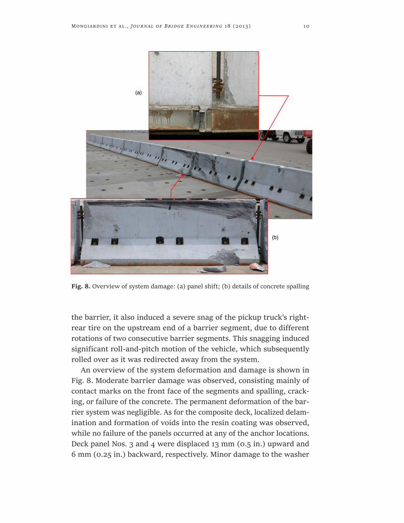
An overview of the system deformation and damage is shown in Fig. 8. Moderate barrier damage was observed, consisting mainly of contact marks on the front face of the segments and spalling, crack-ing, or failure of the concrete. The permanent deformation of the bar-rier system was negligible. As for the composite deck, localized delam-ination and formation of voids into the resin coating was observed, while no failure of the panels occurred at any of the anchor locations. Deck panel Nos. 3 and 4 were displaced 13 mm (0.5 in.) upward and 6 mm (0.25 in.) backward, respectively. Minor damage to the washer
Fig. 8. Overview of system damage: (a) panel shift; (b) details of concrete spalling

Mongiardini et al. , Journal of Bridge Engineering 18 (2013) 11
plate used for the barrier-to-deck connection was observed as well. Although the safety-shape bridge railing system attached to the com-posite panel bridge deck adequately contained the impacting pickup truck, it did not safely redirect the vehicle, which rolled over after the collision with the barrier. Therefore, this bridge railing system was determined to be unacceptable according to the TL-3 safety per-formance criteria of NCHRP Report No. 350 (Ross et al. 1993) when attached to a composite panel bridge deck.
The primary reason for vehicle rollover during the full-scale crash test was found in the excessive snagging of the right-rear wheel at a joint between two barrier segments. This snagging, which occurred on an exposed leaning edge of a barrier module, induced the large roll and pitch vehicle angles that eventually caused the vehicle rollover. Through an analysis of the results obtained from the full-scale crash test, the following contributing factors were identified:
1. A large joint width between barrier modules; 2. The transverse slack between the inner loops and the drop pin; 3. The connection of each module to only one panel; and 4. The additional lateral panel shift attributable to a weak attachment of the deck panels to the girders.
The large joint width between barrier modules, varying between 89 and 102 mm (3.5 and 4 in.), may have allowed the rear wheel (tire and rim) to wedge into the gap and snag on it. Also, the transverse slack between the inner loops and the drop pin may have allowed the upstream module at the joint where the snagging occurred to be pushed backward with respect to the module immediately down-stream, thus creating a larger surface/edge to snag against.
Additionally, other possible reasons for the excessive vehicle snag may be found in the attachment between the barrier and the FRP bridge deck. In fact, the barrier modules were attached to the bridge deck panels using a configuration such that each module was anchored to one deck panel instead of spanning across multiple deck panels. This attachment configuration likely increased (1) the potential for relative shift at a joint of consecutive segments, (2) the lateral barrier move-ment, and (3) the barrier and deck cantilever rotation, which caused

Mongiardini et al. , Journal of Bridge Engineering 18 (2013) 12
a consequent downward movement of the barrier and a reduction of its effective height. All of these factors may have increased vehicle climbing and wheel snag. Finally, the steel plate detail used to attach the deck panels to the girders may have allowed additional panel shift for the laterally loaded panels, thus resulting in an increased expo-sure for wheel snag at barrier gap locations. These mentioned events, either singularly or combined together, may have contributed to cre-ate the conditions for the severe snagging.
Vertical-Faced Concrete Barrier Following the failure of the crash test on the initial design, a vertical face barrier was identified as an improved design for use on the tem-porary composite bridge deck (Smith et al. 2009). A vertical-faced geometry was considered for reducing the vehicle climb on the bar-rier’s steep front face as well as mitigating vehicular instabilities. In addition, a series of changes were implemented to avoid the formation of a wedge at the interface between two consecutive barrier segments.
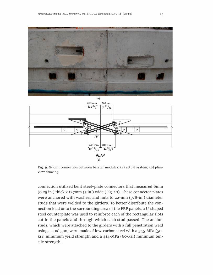
To address the potential hazard represented by the gaps at the bar-rier joints, it was chosen to smoothly and continuously connect con-secutive barrier modules. Furthermore, to increase the joint stiffness, an X-joint, tie-rod assembly (Bligh et al. 2005) was used to connect the ends of adjoining barrier segments, as shown in Fig. 9. The tie rods consisted of 22.2-mm (7/8-in.) diameter, Grade 5 round bars with a plate washer and nut at each end. The upper and lower tie rods were 673 and 762 mm (26.5 and 30 in.) long, respectively. Simple analyt-ical calculations, based on the ultimate resistance under pure shear and tension of the steel bars, indicated that the X-joint had a capacity of approximately 280 and 445 kN (63 and 100 kips) in the direction perpendicular and parallel to the barrier, respectively. For an impact with a 2,270-kg (5,004-lb) pickup at 100 km/h (62 mi/h) and 25°, a peak lateral impact load between 267 and 334 kN (60 and 75 kips) was expected to be applied to the barrier. For impacts close to a bar-rier joint, it was assumed that a maximum of 70% of the load would be transferred to the adjacent barrier segment through the joint con-nection. As such, the X-joint was deemed to be sufficiently strong to sustain an impact at TL-3 conditions.
The panel-to-girder connection was identified as one potential fac-tor that may have contributed to the failure of the first crash test on the initial design. Thus, a stiffer connection was utilized for the crash testing of the vertical-faced barrier. The new stiffer panel to- girder
Mongiardini et al. , Journal of Bridge Engineering 18 (2013) 13
connection utilized bent steel–plate connectors that measured 6mm (0.25 in.) thick x 127mm (5 in.) wide (Fig. 10). These connector plates were anchored with washers and nuts to 22-mm (7/8-in.) diameter studs that were welded to the girders. To better distribute the con-nection load onto the surrounding area of the FRP panels, a U-shaped steel counterplate was used to reinforce each of the rectangular slots cut in the panels and through which each stud passed. The anchor studs, which were attached to the girders with a full penetration weld using a stud gun, were made of low-carbon steel with a 345-MPa (50-ksi) minimum yield strength and a 414-MPa (60-ksi) minimum ten-sile strength.
Fig. 9. X-joint connection between barrier modules: (a) actual system; (b) plan-view drawing

Mongiardini et al. , Journal of Bridge Engineering 18 (2013) 14
Also, longer barrier segments were designed for this second sys-tem such that each barrier module covered multiple deck panels, thus limiting the deflection of the cantilevered deck and better distrib-uting the impact load to multiple deck panels. Although these bar-rier segments were longer than in the previous design, the length was limited enough to not compromise their construction and ease of transportation.
The vertical-faced barrier and FRP deck system are shown in Fig. 11. The total installation length for the vertical-faced, temporary con-crete barrier was 28 m (92 ft) and consisted of six segments attached to the FRP composite bridge deck previously described. Each barrier segment was 4.67 m (15 ft 4 in.) long, with a top and base width of 406 and 229 mm (16 and 9 in.), respectively. The top mounting height was 813 mm (32 in.), as measured from the top of the FRP composite bridge deck to the top of the barrier.
Fig. 10. Deck-to-girder connection: (a) schematic; (b) assembled joint with details of upper and lower plates
Fig. 11. Overview of vertical-faced barrier installed on composite bridge deck

Mongiardini et al. , Journal of Bridge Engineering 18 (2013) 15
Similarly to the previous barrier, each segment was fabricated using air-entrained concrete with a minimum 28-day compressive strength of 34.5 MPa (5,000 psi) and ASTMA615 (2012b) Grade 60 rebars with sizes ranging from No. 4 through No. 6. Each barrier seg-ment utilized 10 longitudinal bars, 46 vertical stirrups, and 23 base loops, with a minimum concrete cover of 38mm (1.5 in.) for all steel reinforcement. Additional design details of the rebar geometry can be found in the project report (Smith et al. 2009).
As for the previously tested system, each barrier segment was fas-tened to the FRP composite bridge deck with anchor rods and heavy hex nuts, using a steel plate washer between the bottom of the deck and the hex nuts at each set of two anchor rod positions, as shown in Fig. 12. The backside toe of each barrier segment was placed 86mm (3.4 in.)
Fig. 12. Details of deck-to-girder attachment and barrier-to-deck connection

Mongiardini et al. , Journal of Bridge Engineering 18 (2013) 16
away from the back edge of the FRP bridge deck panels. In particular, the barrier segments were anchored to the FRP deck panels using an arrangement where the upstream end of the first barrier segment (B1 in Fig. 3) was aligned with the upstream end of the first panel (P1 in Fig. 3). With such configuration, a barrier joint occurred close to a panel joint at the end of barrier segment No. 2, and a vertical anchor rod was located close to the deck joint between panel Nos. 4 and 5.
Full-Scale Testing: Test 2 (Vertical Shape) The 2,028-kg (5,179-lb) pickup truck vehicle impacted the vertical faced barrier at a speed and angle of 98.4km/h (61.1mi/h) and 25.8°, respectively. During this crash test, the vehicle was smoothly redi-rected, as shown in Fig. 13. Moderate lateral movement of the bar-rier segments was observed during the impact event. In particular, the downstream end of module No. 2 deflected backward and the upstream end of module No. 3 both deflected and rotated.
Fig. 13. Sequential view of full-scale scale test with pickup truck and vertical-faced design
Fig. 14. Overview of system damage and details of concrete spalling for vertical-faced design

Mongiardini et al. , Journal of Bridge Engineering 18 (2013) 17
The damage to the barrier was minimal, consisting of contact marks of the front face of the barrier and local spalling and cracking of the concrete (Fig. 14). Spalling occurred along the upper and lower edges of the shelf, around the edges of the threaded rod insets at the down-stream end of module No. 2 as well as on the vertical face of the joint between modules No. 2 and No. 3. No failure was observed in the FRP panels at any of the anchor locations. Also, the maximum dislocation of the panels, which occurred at panel No. 5, was limited to 12.7mm (0.5 in.). Fig. 15 summarizes the test results, including the occupant risk values computed from the measured vehicular accelerations.
Fig. 15. Results summary of full-scale crash test into vertical-faced concrete railing

Mongiardini et al. , Journal of Bridge Engineering 18 (2013) 18
The vehicular loading applied to the concrete barrier system dur-ing the impact event was estimated using the vehicle mass and the 50-ms moving averages of the longitudinal and lateral vehicle accel-erations, which were converted to a global coordinate system using the vehicle yaw angle with respect to time. The impact forces perpen-dicular and parallel to the system are provided in Fig. 16. The maxi-mum perpendicular load imparted to the barrier was approximately 338 kN (76 kips).
Conclusions and Discussion
The aim of this research project was to develop, test, and investigate the safety performance of a concrete railing for attachment to an FRP temporary bridge deck system. An initial barrier design involving a New Jersey shape parapet did not meet the minimum safety require-ments from vehicle rollover likely caused by severe right-rear tire snag on the exposed end of a barrier module, which resulted from excessive relative deflection between barrier modules. The main reason for this relative deflection of the New Jersey-type barrier modules was iden-tified to be in the large downward and backward displacement of the deck during the impact event. Thus, the adoption of an F-shape safety profile would not likely have prevented the vehicle climb on the bar-rier face and the subsequent rollover.
To limit the vehicle roll motion and avoid wheel snag, several modi-fications were implemented, including the use of a smother and stiffer
Fig. 16. Impact force versus time: perpendicular and tangential components

Mongiardini et al. , Journal of Bridge Engineering 18 (2013) 19
connection between the modules and a more rigid attachment of the deck composite panels to the girders. These modifications as well as the use of a vertical-faced barrier that limited the propensity for the vehicle to climb up the barrier face contributed to the success-ful performance observed in the second full-scale crash test. Further-more, the crash test on the vertical-faced barrier met the more severe requirements of the MASH (2009) impact safety standards. Following the successful testing of the vertical-faced barrier attached to the FRP composite deck panels, an application seeking an official acceptance from the Federal Highway Administration, Washington, DC, was sub-mitted and is pending.
Although the crash test with the New Jersey-type barrier did not pass the safety criteria, solutions similar to those adopted for the vertical-faced design would likely have allowed the safety shape to meet the MASH (2009) criteria. In any case, a full-scale crash test is the only method to confirm the safety performance of any proposed modifications.
Modifications to the geometry and architecture of the FRP deck panels could affect the safety performance of the successfully tested railing system. In situations where wider FRP deck modules are desired, it would be important to ensure that each barrier segment is placed over a minimum of two deck panels. Also, the cantilevered length of the composite deck panels from each girder should be sim-ilar to that used in the as-tested deck in order to maintain a flexural behavior of the FRP composite modules similar to that observed for the crash-tested system. On the other side, it is also possible that, if the deck rotation is limited below the level observed in the full-scale crash testing, higher impact forces and loads transferred to the deck may be expected. Hence, considerable variations to these character-istics could require retesting any modified design.
The experience from the two full-scale tests has shown the neces-sity to limit the lateral movement of the barrier modules through a stiff and strong connection between the composite deck and both the bridge girders and barrier modules. Although the connection has to guarantee a firm linkage, it also has to avoid producing excessive local damage to the composite deck during an impact event. Alternative designs for the composite FRP deck modules (e.g., material specifi-cations, reduced thickness of the layers, and geometrical properties of the honeycomb) may lead to an increased flexibility of the panels

Mongiardini et al. , Journal of Bridge Engineering 18 (2013) 20
or localized damage at the anchorage locations. As such, where vari-ations in the architecture of the composite deck design are expected to either increase or decrease the deck flexibility, or increase the pro-pensity for local damage, the vertical-faced barrier system and its connections should be retested and evaluated accordingly.
Acknowledgments – The authors acknowledge the Kansas DOT for sponsoring this project, the Bridge Design Team of BG Consultants Inc. for the design of the barrier systems, Kansas Structural Composites for providing the composite panels, and the researchers at the Midwest Roadside Safety Facility for their contributions to the completion of this project.
References
ASTM. (2012a). “Standard specification for carbon structural steel.” A36, West Conshohocken, PA.
ASTM. (2012b). “Standard specification for deformed and plain carbon steel bars for concrete reinforcement.” A615, West Conshohocken, PA.
Bligh, R. P., Sheikh, N. M., Menges, W. L., and Haug, R. R. (2005). “Development of low-deflection precast concrete barrier.” Rep. No. FHWA/ TX-05/0-4162-3, final Rep. to the Federal Highway Administration, Office of Safety and Traffic Operations R&D, Texas Transportation Institute, Texas A&M Univ., College Station, TX.
Bronstad, M. E., Calcote, L. R., and Kimball, C. E., Jr. (1976). “Concrete median barrier research. Vol. 2: Research report.” Rep. No. FHWA-RD- 77-4, Submitted to the Office of Research and Development, Federal Highway Administration, Southwest Research Institute, San Antonio, TX.
Buth, C. E., Campise,W. L., Griffin, L. I., III, Love, M. L., and Sicking, D. L. (1986). “Performance limits of longitudinal barrier systems. Vol. I: Summary report.” Rep. No. FHWA/RD-86/153, Final Rep. to the Federal Highway Administration, Office of Safety and Traffic Operations R&D, Texas Transportation Institute, Texas A&M Univ., College Station, TX.
Cheng, L., and Karbhari, V. M. (2006). “New bridge systems using FRP composites and concrete: A state-of-the-art review.” Prog. Struct. Eng. Mater., 8(4), 143–154.
Fortuniewicz, J. S., Bryden, J. E., and Phillips, R. G. (1982). “Crash tests of portable concrete median barrier for maintenance zones.” Rep. No. FHWA/NY/RR-82/102, Final Rep. to the Office of Research, Development, and Technology, Federal Highway Administration, Engineering Research and Development Bureau, New York State DOT, Nesconset, NY.
MASH. (2009). Manual for assessing safety hardware (MASH). AASHTO, Washington, DC.

Mongiardini et al. , Journal of Bridge Engineering 18 (2013) 21
Ross, H. E., Sicking, D. L., Zimmer, R. A., and Michie, J. D. (1993). “Recommended procedures for the safety performance evaluation of highway features.” Rep. No. 350, National Cooperative Research Program (NCHRP), Transportation Research Board, Washington, DC.
Smith, J. D., Faller, R. K., Polivka, K. A., Sicking, D. L., and Reid, J. D. (2009). “Development and testing of a new vertical-faced temporary concrete barrier for use on composite panel bridge decks.” Transportation Research Report No. TRP-03-220-09, Final Rep. to the Kansas Department of Transportation, Midwest Roadside Safety Facility, Univ. of Nebraska-Lincoln, Lincoln, NE.
Stolle, C. S., Polivka, K. A., Faller, R. K., Rohde, J. R., and Sicking, D. L. (2007). “Evaluation of a New Jersey safety shape, segmented concrete barrier for use on composite panel bridge decks.” Transportation Research Report No. TRP-03-181-07, Final Rep. to the Kansas Department of Transportation, Midwest Roadside Safety Facility, Univ. of Nebraska- Lincoln, Lincoln, NE.
Tang, B., and Podolny, W. (1998). “A successful beginning for fiber reinforced polymer (FRP) composite materials in bridge applications.” Proc., Int. Conf. on Corrosion and Rehabilitation of Reinforced Concrete Structures, Federal Highway Administration (FHWA), Washington, DC.
Zhao, L., Karbhari, V. M., Hegemier, G. A., and Seible, F. (2004). “Connection of concrete barrier rails to FRP bridge decks.” Compos., Part B Eng., 35(4), 269–278.