design and testing of an experimental magnetorheological
TRANSCRIPT
Strojarstvo 52 (6) 601-614 (2010) Z. HEROLD et. al., Design and Testing of an Experimental... 601Design and Testing of an Experimental... 601 601
CODEN STJSAO ISSN 0562-1887 ZX470/1481 UDK 621.825-11:62-578:681.511
Original scienfic paper
Owing to very good controllability, simple design, and durability, magnetorheological fluid (MRF) clutches become attractive solutions for various industrial and automotive applications. An experimental MRF clutch has been developed at the University of Zagreb, in order to support MRF clutch modeling, and control research. The clutch design facilitates MRF handling, change of fluid gap width, and testing various types of seals. The paper first presents calculation of the main clutch design parameters. Next, design of the overall clutch mechatronic system is described. Finally, the main results of testing the clutch static and transient behaviors are presented and compared with the design parameters.
Projektiranje i ispitivanje eksperimentalne magnetoreološke spojke
Izvornoznanstveni članakZahvaljujući veoma dobrom svojstvu upravljanja, jednostavnoj konstrukciji i izdržljivosti, spojke temeljene na magnetoreološkim fluidima nalaze sve širu primjenu u industriji i tehnici motornih vozila. Eksperimentalna magnetoreološka spojka razvijena je na Sveučilištu u Zagrebu da bi se potakla istraživanja na području modeliranja i regulacije magnetoreoloških spojki. Spojka je konstruirana tako da olakša rukovanje fluidom, te omogući promjenu širine fluidnog raspora i primjenu raznih vrsta brtvi. Članak prvo izlaže proračun glavnih konstrukcijskih parametara spojke. Zatim se opisuje cjelokupni mehatronički sustav spojke. Konačno, prikazuju se glavni rezultati ispitivanja statičkog i dinamičkog ponašanja spojke, koji se uspoređuju s projektnim parametrima.
Zvonko HEROLD1), Domagoj LIBL2) and Joško DEUR1)
1) Fakultet strojarstva i brodogradnje, Sveučilište u Zagrebu (Faculty of mechanical Engineering and Naval Architecture), Ivana Lučića 5, HR-10000 Zagreb Republic of Croatia
2) INETEC Institut za nuklearnu tehnologiju (Institute for Nuclear Technology), Dolenica 28, HR-10000 Zagreb, Republic of Croatia
Keywords Clutch Control Design Experimental analysis Magnetorheological fluid Testing
Ključne riječi Eksperimentalna analiza Ispitivanje Magnetoreološki fluid Projektiranje Regulacija Spojka
Received (primljeno): 2010-04-28 Accepted (prihvaćeno): 2010-10-29
Design and Testing of an Experimental Magnetorheological Fluid Clutch
1. Introduction
The magnetorheological fluid (MRF) and related clutch devices were invented at the National Bureau of Standards by Jacob Rabinow in 1940s [1]. Rabinow proposed to use fine (micron-sized) iron particles suspended in fluid and exposed to the magnetic field. By changing the solenoid current, and thus the magnetic field, rheological properties of the MRF change, thereby resulting in the clutch torque change. The MRF clutches did not find their application until 1990s, because of practical difficulties related to particle settling, fluid thickening, and fluid sealing [2-3]. The R&D efforts in 1950s were, thus, turned to dry magnetic particle (MP) clutches, which where later used as standard industrial
clutches [4]. Once the MRF difficulties were resolved in the 1990s [3], the MRF clutches have again become an attractive solution because the fluid suspension prevents packing of magnetic particles and provides a smooth, silent, durable, and consistent behavior.
The main advantages of MRF clutches and brakes when compared with electrical motors include a superior torque/volume ratio (up to 10 times higher), high torque/inertia ratio, smooth torque response (no torque pulsations), and extremely small electrical power requirements (e.g. 10-20 W for torques of up to 100 Nm). Compared to frictional clutches, the MRF clutches are characterized by simpler design (due to purely electromagentic actuation), better controllability (torque response is fast, repeatable, and proportional to current) and better durability (a

602 Z. HEROLD et. al., Design and Testing of an Experimental... Strojarstvo 52 (6) 601-614 (2010)
Symbols/Oznake
AFe1 - area of side part of yoke (column), m2 - površina bočnog dijela jarmaAMRF - active MR fluid area, m2 - površina aktivnog dijela MR fluidaACu,sol - active area of solenoid, m2 - aktivna površina zavojniceAsol - total area of solenoid, m2 - ukupna površina zavojniceBFe1 - magnetic flux density in steel, T - magnetska indukcija u željezuBMRF - magnetic flux density in MR fluid, T - magnetska indukcija u MR fluidudc - column width, m - širina bočnog dijela jarmadFe - slot width, m - širina magnetskog limady - yoke height, m - visina jarmaHMRF - magnetic field in MR fluid, A/m - magnetsko polje u MR fluiduI - solenoid current, A - struja zavojniceJ - solenoid current density, A/m - gustoća struje zavojniceKfring - magnetic flux fringing factor - faktor rasipanja magnetskog tokaKfil, sol - solenoid filling factor - faktor popunjenosti zavojniceL - solenoid inductance, H - induktivitet zavojnicelFe1 - mean length of yoke, m - srednja duljina jarmalFe2 - disk width, m - širina diskalsol - solenoid height, mv - visina zavojnicelsol, iso - solenoid bed height, m - visina izolacijskog sloja zavojniceM - clutch net torque, Nm - razvijeni moment spojkeMv - clutch viscous torque, Nm - viskozni moment spojke
N - number of turns - broj zavojaNMRF - number of MRF gaps - broj raspora s MR fluidomNI - total magnetomotive force, A - ukupno magnetsko protjecanje(NI)MRF - magnetomotive force in MR fluid, A - magnetsko protjecanje u MR fluidup - electric power, W - električna snagar - solenoid resistance, Ω - otpor zavojnicer0 - outer radius of disk, m - vanjski polumjer diskari - inner radius of disk, m - unutarnji polumjer diskari - inner radius of MR fluid gap, m - unutarnji polumjer raspora s MR fluidomriy - outer radius of solenoid, m - vanjski polumjer zavojnicer - radial coordinate, m - radijalna koordinatas - fluid gap width, m - širina raspora s MR fluidomTec - time constant due to the eddy current effect, s - vremenska konstanta vezana uz učinak vrtložnih strujaTel - solenoid time constant, s - vremenska konstanta zavojniceWsol - solenoid width, m - širina zavojniceη - fluid viscosity, Pa - viskozitet fluidaρFe - specific resistance of steel, Ωm2/m - specifični otpor željezaρCu - specific resistance of copper, Ωm2/m - specifični otpor bakraτyd - yield stress, Pa - naprezanje tečenjaФ - polar angle, rad - polarni kutω - clutch slip speed, rad/s - brzina klizanja spojke
low level of wear). Typical industrial applications include devices comprising unwind/rewind, soft start, overload protection, and safe load holding operations [1, 4]. Characteristic automotive applications are active differentials [5–7], auxiliary engine devices such as fans [8], and steer-by-wire systems [9]. Besides the clutches/brakes, the MRF devices include active dampers that are used, for instance, in semi-active suspensions [9-10].
The MRF clutch design needs to satisfy quite opposite requirements on large torque/drag ratio, fast torque response, low power consumption, effective sealing, and stable operation without particle separation due to centrifuging [11]. Although a major part of clutch design can be conducted by using advanced, multi-physics, computer-aided design tools, the final design verification and possible modifications are based on extensive experimental tests.

Strojarstvo 52 (6) 601-614 (2010) Z. HEROLD et. al., Design and Testing of an Experimental... 603Design and Testing of an Experimental... 603 603
This paper presents design of an experimental disk-type stationary MRF clutch (a brake) and related test rig, which have been primarily aimed at clutch modeling and control research [12-13]. The design provides ease of fluid manipulation, change of fluid thickness, and use of different fluid seals. The magnetic core is laminated to minimize the influence of eddy currents on the clutch torque response time [11,14]. The clutch is equipped with a tiny thermocouple and a magnetic flux sensor, which are placed near the fluid gap. The clutch rotor is driven by an electric servo-motor, while its stator is constrained by a precise force/torque sensor. By replacing the MRF medium by magnetic particles, the clutch may be used as an MP clutch.
The paper also presents the results of experimental characterization of the clutch static and dynamic behaviors. This includes the torque vs. current static curves, torque vs. speed curves, breakaway curves, current and torque transient responses, and thermal transient responses. The recorded curves are used to identify the main clutch static and dynamic parameters, which are then compared with the design parameters.
2. Clutch design
2.1. Calculation of clutch design parameters
The MRF clutch is to be tested by using resources of the existing experimental setup of internal combustion engine loaded by an electrical servo-motor [15]. The starting design parameters are, thus, determined by what follows:
The rated clutch torque (for a linear torque vs. current • static curve) should match the maximum torque M = 28 Nm of the driving servo-motor,The inner radius • ri of active (magnetic) part of the clutch disk should not be smaller than 45 mm to provide adequate clutch connection to the servo-motor motor shaft (see Subsection 2.2).
The clutch design is based on the common equations for the clutch torque and electromagnetic quantities [11,16]. The clutch cross-sectional view is shown in Figure 1 (see Figure 5 for the clutch 3D drawing and photograph). The fluid MRF-132DG has been supplied by the Lord Corporation.
Choosing the inner and outer clutch disk radii ri = 0,0465 m and ro = 0,0705 m, respectively, gives the net torque
(1)
where NMRF = 2 is the number of MRF gaps and τyd = 30000 Pa is the Lord MRF-132DG fluid rated yield stress for the linear static curve (Figure 2a). Note that the realistic assumption of uniform yield stress distribution along the disk cross-sectional area is assumed (τyd ≠ f(r,Φ), non-uniformity of the magnetic field and the particle centrifuging effect are neglected [11]). The viscous torque (drag) is obtained as
Figure 1. Cross-sectional views of MRF clutch active partSlika 1. Uzdužni presjek MRF spojke u radnom dijelu
(2)

604 Z. HEROLD et. al., Design and Testing of an Experimental... Strojarstvo 52 (6) 601-614 (2010)
where is the fluid shear rate, η = 0.12 Pa is the fluid viscosity estimate [11], ω = 100 rad/s is the slip speed, s = 2 mm is the fluid gap width, and ri= 0.025 m is the true inner radius of the disk (active and inactive area, cf. Figures 1 and 5a). Note that the fluid gap width s is chosen to a minimum value of 2 mm that still prevents particle centrifuging [11].
The magnetomotive force (MMF) related to the rated magnetic field in the MRF gaps, HMRF = 100⋅103 A/m (Figure 2a), is given by
(3)
In order to cover the MMF drops in magnetic core and slot lacquer, the total MMF is increased toNI = 568 A
Based on a typical solenoid current density J = 4 A/mm2 and the solenoid filling factor Kfill,sol = 71 %, the following net and total solenoid areas are obtained:
(4)
(5)For the solenoid width Wsol = 8 mm and the wire area
ACu = 2.54 mm2, this gives the solenoid length lsol and the number of turns N (Figure 1):
Slika 2. MRF static curves [17] with operating point denotedSlika 2. Statičke karakteristike MRF [17] s prikazom statičke radne točke
(6)
(7)The main solenoid electrical parameters are obtained
as follows (note that liso,sol = 3.5 mm, Figure 1; and ρCu = 0.0175 Ωmm2/m is the specific resistance of copper):
(8)
(9)
(10)
(11)
The solenoid inductance reads
(12)
where BMRF = 0.6 T is the rated magnetic flux density (Figure 2b) and is the active fluid area (Figure 1) with Kfring = 1,05 denoting the magnetic flux fringing factor. The corresponding solenoid time constant Tel and the additional time constant due the eddy current effect [11], Tec, are given by
(13)
(14)
where dFe [mm] is the thickness of laminated core slots, µr0 ≅ 5000 is the zero-field relative permeability of steel, and ρFe [Ωmm2/m] is the specific resistance of steel (ρFe ≅ 0.135 Ωmm2/m). The slot width is chosen to dFe = 3 mm to provide a reasonably small eddy-current time constant Tec << Tel. Note that if the core were not laminated, Tec would be very large (up to 1 s), which would substantially affect the clutch control performance (cf. [14]).
The column width dc is obtained from the condition on equivalence of the magnetic flux in the MRF gap and the column (Figure 1):
which gives
(15)
for the the steel flux density chosen to BFe1 = 1.2 T.
Strojarstvo 52 (6) 601-614 (2010) Z. HEROLD et. al., Design and Testing of an Experimental... 605Design and Testing of an Experimental... 605 605
Similarly, the yoke height dy is obtained from the
condition (Figure 1): with riy = ro + lsol + 2lsol,iso = 102,5 mm. This leads to the square equation
(16)
with the solutiondy = 7 mm.
Thus, each column is composed of four slot pairs each with the width of 3 mm, and the yoke includes two slots (rings) with the height of 3.5 mm (see Figure 5a). The disk is also slotted by using six rings with the height
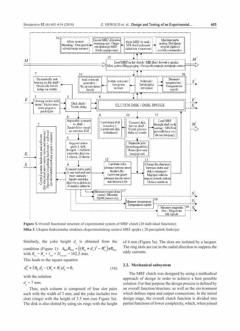
Figure 3. Overall functional structure of experimental system of MRF clutch (20 individual functions)Slika 3. Ukupna funkcionalna struktura eksperimentalnog sustava MRF spojke ( 20 parcijalnih funkcija)
of 4 mm (Figure 5a). The slots are isolated by a lacquer. The ring slots are cut in the radial direction to suppres the eddy currents.
2.2. Mechanical subsystem
The MRF clutch was designed by using a methodical approach of design in order to achieve a best possible solution. For that purpose the design process is defined by an overall function/structure, as well as the environment which defines input and output connections. In the initial design stage, the overall clutch function is divided into partial functions of lower complexity, which, when joined
606 Z. HEROLD et. al., Design and Testing of an Experimental... Strojarstvo 52 (6) 601-614 (2010)
together through relations, give the overall clutch system functional structure (Figure 3). This functional structure enables more alternatives of the conceptual solution to be found and created. However, only the implemented solution is presented here, which is based on the use of an existing servo-motor to drive the experimental clutch.
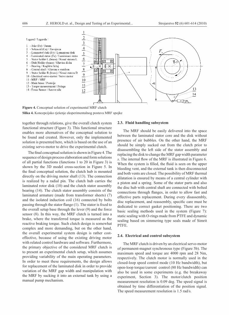
The final conceptual solution is shown in Figure 4. The sequence of design process elaboration and form solutions of all partial functions (functions 1 to 20 in Figure 3) is shown by the 3D model cross-section in Figure 5. In the final conceptual solution, the clutch hub is mounted directly on the driving motor shaft (13). The connection is realized by a radial pin. The clutch hub carries the laminated rotor disk (10) and the clutch stator assembly bearing (14). The clutch stator assembly consists of the laminated armature (made from transformer sheets) (7) and the isolated induction coil (16) connected by bolts passing through the stator flange (1). The stator is fixed to the overall setup base through the lever (9) and the force sensor (8). In this way, the MRF clutch is turned into a brake, where the transferred torque is measured as the reactive braking torque. Such clutch design is somewhat complex and more demanding, but on the other hand, the overall experimental system design is rather cost-effective, because of using the existing driving motor with related control hardware and software. Furthermore, the primary objective of the considered MRF clutch is to present an experimental clutch setup, which assumes providing variability of the main operating parameters. In order to meet these requirements, the design allows for replacement of the laminated disk in order to provide variation of the MRF gap width and manipulation with the MRF by sucking it into an external tank by using a manual pump mechanism.
Figure 4. Conceptual solution of experimental MRF clutchSlika 4. Koncepcijsko rješenje eksperimentalnog postava MRF spojke
2.3. Fluid handling subsystem
The MRF should be easily delivered into the space between the laminated stator core and the disk without presence of air bubbles. On the other hand, the MRF should be simply sucked out from the clutch prior to disassembling the left side of the stator assembly and replacing the disk to change the MRF gap width parameter s. The internal flow of the MRF is illustrated in Figure 6. When the system is filled, the fluid is seen on the upper bleeding vent, and the external tank is then disconnected and both vents are closed. The possibility of MRF thermal dilatation is ensured by means of a central cylinder with a piston and a spring. Some of the stator parts and also the disc hub with central shaft are connected with bolted connections through flanges, in order to allow fast and effective parts replacement. During every disassembly, disc replacement, and reassembly, specific care must be dedicated to correct gasket positioning. There are two basic sealing methods used in the system (Figure 7): static sealing with O-rings made from PTFE and dynamic sealing based on simmering type seals made of Simrit PTFE.
2.4. Electrical and control subsystem
The MRF clutch is driven by an electrical servo-motor of permanent-magnet synchronous type (Figure 5b). The maximum speed and torque are 4000 rpm and 28 Nm, respectively. The clutch motor is normally used in the closed-loop speed control mode (10 Hz bandwidth), but open-loop torque/current control (80 Hz bandwidth) can also be used in some experiments (e.g. the breakaway experiment, Section 3). The motor/clutch position measurement resolution is 0.09 deg. The speed signal is obtained by time differentiation of the position signal. The speed measurement resolution is 1.5 rad/s.
Strojarstvo 52 (6) 601-614 (2010) Z. HEROLD et. al., Design and Testing of an Experimental... 607Design and Testing of an Experimental... 607 607
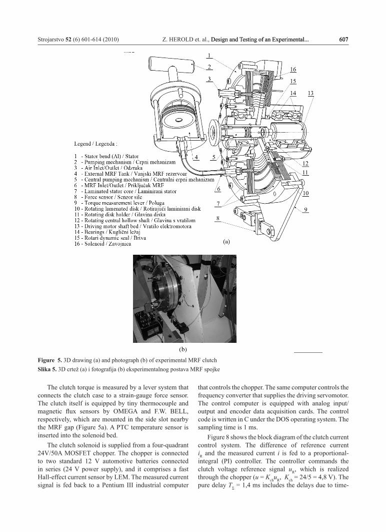
Figure 5. 3D drawing (a) and photograph (b) of experimental MRF clutchSlika 5. 3D crtež (a) i fotografija (b) eksperimentalnog postava MRF spojke
The clutch torque is measured by a lever system that connects the clutch case to a strain-gauge force sensor. The clutch itself is equipped by tiny thermocouple and magnetic flux sensors by OMEGA and F.W. BELL, respectively, which are mounted in the side slot nearby the MRF gap (Figure 5a). A PTC temperature sensor is inserted into the solenoid bed.
The clutch solenoid is supplied from a four-quadrant 24V/50A MOSFET chopper. The chopper is connected to two standard 12 V automotive batteries connected in series (24 V power supply), and it comprises a fast Hall-effect current sensor by LEM. The measured current signal is fed back to a Pentium III industrial computer
that controls the chopper. The same computer controls the frequency converter that supplies the driving servomotor. The control computer is equipped with analog input/output and encoder data acquisition cards. The control code is written in C under the DOS operating system. The sampling time is 1 ms.
Figure 8 shows the block diagram of the clutch current control system. The difference of reference current iR and the measured current i is fed to a proportional-integral (PI) controller. The controller commands the clutch voltage reference signal uR, which is realized through the chopper (u = KchuR, Kch = 24/5 = 4,8 V). The pure delay TΣ = 1,4 ms includes the delays due to time-

608 Z. HEROLD et. al., Design and Testing of an Experimental... Strojarstvo 52 (6) 601-614 (2010)
discretization, speed measurement, and control algorithm computation. The process model transfer functions i(s)/uR(s) and M(s)/i(s) are obtained from a transformer-like clutch model including the eddy current effect [12-13]. The current response i(t) is faster than the torque response M(t), because of the presence of lead time constant Tec in
Figure 6. MRF Circuit – internal MRF flow Slika 6. Kruženje MRF – unutrašnji tok fluida
Figure 7. MRF Circuit – static and dynamic seals Slika 7. Kruženje MRF – statičko i dinamičko brtvljenje
the transfer function i(s)/uR(s). The PI controller is tuned according to the technical optimum criterion [18], where Tc = Tel is chosen to speed up the current response and the gain Kc is set to provide the fastest aperiodic current response (see [12] for more detail on control system design).
Figure 8. Block diagram of clutch current control systemSlika 8. Blokovski dijagram regulacijskog kruga
ecch s
el ec
1( ) 1
T sK KT T s
++ +
iM
ec 1K
T s +MRu
sTe Σ−cc
c
1T sKT s
+Ri +
-
PI Controller / IP Regulator
Computational and ZOH delay/Kašnjenje
uslijed numerike i ekstrapolacije
Process /Proces

Strojarstvo 52 (6) 601-614 (2010) Z. HEROLD et. al., Design and Testing of an Experimental... 609Design and Testing of an Experimental... 609 609
3. Clutch testingResults of testing the clutch static and transient
behaviors are presented in this section. The test results have been used in [12] for parameterizing and validating the clutch dynamics model.
0
0.5
1
0.8 1 1.2 1.4 1.6 1.8 2 2.2 2.4-2
0
2
4
6
8
10
12
0.8 1 1.2 1.4 1.6 1.8 2 2.2 2.4
[s] t
[A]
ich
RK
uu
/
[V
]
=
Experiment / Eksperiment
Simulation / Simulacija
Figure 9. Clutch current response with respect to stepwise voltage changeSlika 9. Vremenski odziv struje na skokovitu promjenu napona
3.1. Current and torque transient responses
The clutch current response i(t) with respect to stepwise change of the commanded voltage uR is shown
in Figure 9. A good agreement between the experimental and computer-simulation responses indicates that the lead-lag transfer function model i(s)/uR(s) in Figure 8 can accurately describe the clutch current response. The identified model parameters are: Ks = 1/r = 2,4 Ω-1, Tel = 60 ms , Tec = 25 ms . The identified resistance r = 1/Ks = 0,42 Ω is larger than the theoretical solenoid resistance value r’ = 0,21 Ω (Subsection 2.1), because of the influence of battery, wire, and MOSFET resistances. Also, the flux density is reduced from its theoretical value (B = s’/s⋅B’; see Eq. (3) and Figure 2b) due to the increase of MRF gap from s’ = 2 mm to s = 3 mm. Accordingly, the electrical time constant given by Eq. (13) should be corrected as Tel = (s’r’) / (sr)⋅Tel’ = 49 ms, which is in a good agreement with the identified value of 60 ms. The identified eddy-current time constant Tec = 25 ms is in a reasonable agreement with the roughly predicted value of 42 ms based on Eq. (14).
Figure 10 shows the closed-loop current responses and the corresponding normalized clutch torque responses with respect to different magnitudes of current reference (iR) step change. The current response is very fast in accordance with the small closed-loop time constant achieved (Teq = 6 ms). On the other hand, the clutch torque response is slower due to the effect of eddy current lag term 1 / (Tecs + 1) that remains outside the current control loop (Figure 8). The torque response settling time is around 50 ms. Comparison of the simulation and experimental responses in Figure 10 further confirms the accuracy of linear current model in Figure 8. However, the torque model is rather inaccurate for the torque off phase. Namely, the experimental response is initially steep, which is also seen in the magnetic flux sensor response (Figure 11). In addition, the torque model exhibits a steady-state inaccuracy in the case of non-zero initial current (see the lowest subplot in Figure 10). Both
Figure 10. Step responses of current control closed-loop system, including normalized torque responsesSlika 10. Vremenski odziv regulacijskog kruga struje na skokovitu promjenu reference uključujući normirani odziv momenta
0.4 0.5 0.6 0.7 0.8 0.9 1
0
1
2
-1
0
1
2
3
0
2
4
6
4
5
6
7
02468
10
0.4 0.5 0.6 0.7 0.8 0.9 1
0.4 0.5 0.6 0.7 0.8 0.9 1
0.4 0.5 0.6 0.7 0.8 0.9 1
0.4 0.5 0.6 0.7 0.8 0.9 1
Sim. - [A] i Exp. - [A] i Sim. - [A] M Exp. - [A] M
[s] t
[s] t

610 Z. HEROLD et. al., Design and Testing of an Experimental... Strojarstvo 52 (6) 601-614 (2010)
inaccuracies are predominantly caused by the nonlinear effect of magnetic hysteresis (see next subsection), and they can be largely reduced by using a nonlinear model of the clutch electromagnetic circuit, as proposed in [13].
0.4 0.5 0.6 0.7 0.8 0.9 1150
200
250
300
350
400
[ s] t
Flux
sens
or re
adin
g /
oèi
tanj
e se
nzor
a to
ka,
[V
]
Figure 11. Magnetic flux sensor reading during the current control system step response (i: 0 → 5A) from Figure 10Slika 11. Vremenski odziv senzora magnetskog toka na skokovitu promjenu reference struje (i: 0 → 5A) prikazanog na slici 10
3.2. Static curves
3.2.1. Torque vs. current curvesExecuting the quasi-steady-state closed-loop
experiment with zero initial current (see the very top subplot of Figure 12) has given the net-torque vs. current static curves shown in Figure 12a. The static curves for non-zero initial current are shown in Figure 12b. As projected by the design (Subsection 2.1, Figure 2a), the static curves in Figure 12a have a linear shape. The rated net torque of 20,5 Nm agrees very well with the scaled theoretical value M’ = s/s’⋅M = 20.9 Nm obtained from Eq. (1). The static curves in Figure 12 include hysteretic loops caused by the magnetic hysteresis. The higher the current amplitude, the narrower the hysteresis. For the non-zero initial current, the torque is somewhat different for the same current depending on whether the current is growing or falling (see Figure 12b and the related discussion on steady-state inaccuracy of torque control from Subsection 3.1).
Static curve points above the rated current of 10 A can be recorded by using a clutch stopping experiment illustrated in the top subplot of Figure 13 (note that the motor torque was not large enough for the static experiment). The results in Figure 13 show that the clutch torque can be significantly increased over the rated one, which is partly due to the increased MRF gap s’/s = 1,5 and partly due to the torque reserve in the MRF static curve in Figure 2a.
Figure 12. Torque vs. current static curves (ω = 100 rpm)Slika 12. Statička karakteristika momenta u ovisnosti o struji (ω = 100 min-1)
Figure 13. Extended torque vs. current static curveSlika 13. Proširena statička karakteristika momenta u ovisnosti o struji
Strojarstvo 52 (6) 601-614 (2010) Z. HEROLD et. al., Design and Testing of an Experimental... 611Design and Testing of an Experimental... 611 611
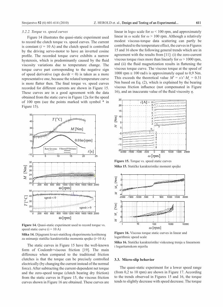
3.2.2. Torque vs. speed curvesFigure 14 illustrates the quasi-static experiment used
to record the clutch torque vs. speed curves. The current is constant (i = 10 A) and the clutch speed is controlled by the driving servo-motor to have an inverted cosine profile. The recorded torque curve exhibits a narrow hysteresis, which is predominantly caused by the fluid viscosity variations due to temperature change. The torque curve part corresponding to the negative sign of speed derivative (sgn dω/dt < 0) is taken as a more representative one, because the related temperature curve is more flatter then. The final torque vs. speed curves recorded for different currents are shown in Figure 15. These curves are in a good agreement with the data obtained from the static curve in Figure 12a for the speed of 100 rpm (see the points marked with symbol * in Figure 15).
0 5 10 15 20 25-10
0
10
20
30
40
50
0 200 400 600 800 1000 1200 1400 1600 1800 200020
22
24
26
28
30
0 200 400 600 800 1000 1200 1400 1600 1800 200010
20
30
40
50
[s] t
[rpm] ω
Filtered/Filtrirano
C][ oT
0sgn >ω
C]
[ oT
[Nm
]
M
[Nm] M
[rpm] 01.0 ω
Raw/Izvorno
[rpm] ω
0sgn <ω
Figure 14. Quasi-static experiment used to record torque vs. speed static curve (i = 10 A)Slika 14. Dijagrami kvazi-statičkog eksperimenta korištenog za snimanje statičke karakteristike momenta spojke (i=10 A)
The static curves in Figure 15 have the well-known form of Coulomb+viscous friction [19]. The main difference when compared to the traditional friction clutches is that the torque can be precisely controlled electrically (by changing the current instead of the normal force). After subtracting the current-dependent net torque and the zero-speed torque (clutch bearing dry friction) from the static curves in Figure 15, the viscous friction curves shown in Figure 16 are obtained. These curves are
linear in logω scale for ω < 100 rpm, and approximately linear in ω scale for ω > 100 rpm. Although a relatively modest viscous-torque data scattering can partly be contributed to the temperature effect, the curves in Figures 15 and 16 show the following general trends which are in agreement with the results from [11]: (i) the zero-current viscous torque rises more than linearly for ω > 1000 rpm, and (ii) the fluid magnetization results in flattening the viscous torque curve. The viscous torque at the speed of 1000 rpm ≅ 100 rad/s is approximately equal to 0,9 Nm. This exceeds the theoretical value M’ = s/s’⋅Mv = 0.31 Nm based on Eq. (2), which is explained by the bearing viscous friction influence (not compensated in Figure 16), and an inaccurate value of the fluid viscosity η.
Figure 15. Torque vs. speed static curvesSlika 15. Statičke karakteristike moment spojke
Figure 16. Viscous torque static curves in linear and logarithmic speed scaleSlika 16. Statičke karakteristike viskoznog trenja u linearnom i logaritamskom mjerilu
3.3. Micro-slip behavior
The quasi-static experiment for a lower speed range (from 0,2 to 10 rpm) are shown in Figure 17. According to the trends observed in Figures 15 and 16, the torque tends to slightly decrease with speed decrease. The torque

612 Z. HEROLD et. al., Design and Testing of an Experimental... Strojarstvo 52 (6) 601-614 (2010)
the driving motor torque rise under the locked clutch conditions. More precisely, the presliding displacement (as observed in [11]) is here less than the position measurement resolution of 0,09 o, i.e. the locked clutch torsional stiffness is larger than 12700 Nm/rad.
0 5 10 15 20 25-10
0
10
20
30
[s] t
[Nm] M ][ oεmRM [Nm]
Figure 19. Presilding displacement experiment responseSlika 19. Vremenski dijagram relativnog pomaka u fazi držanja
Figure 17. Quasi-static experiment results in low-speed (Stribeck) regionSlika 17. Vremenski dijagrami kvazi-statičkih eksperimenata u području malih brzina klizanja (Stribeckovo područje)0 2 4 6 8 10 12 14 16 18 20
-505
10152025
0 2 4 6 8 10 12 14 16 18 20-5
0
5
10
15
200 2 4 6 8 10 12 14 16 18 20
-5
0
5
10
15
0 2 4 6 8 10 12 14 16 18 20-5
0
5
10
150 2 4 6 8 10 12 14 16 18 20
-5
0
5
10
15
[s] t [s] t
[Nm] M [rpm] ω
A 0=i
A 2=i
A 4=i
A 7=i
A 10=i
[rpm] Rω(Filtered /Filtrirano)
is smooth and the speed is precisely controlled for small clutch currents (i ≤ 2 A). However, at larger currents the torque can abruptly increase towards stiction value, the clutch temporarily locks, and a stick-slip behavior can occur. This effect corresponds to the falling Stribeck friction curve [19]. The zero-speed torque decay is steep, i.e. the stiction torque excess vanishes at very small speeds.
Figure 18 shows the results of a clutch breakaway experiment for different clutch currents. In this experiment, the locked clutch with a constant current is exposed to a slow linear rise of the driving motor torque until the clutch breakaways and exceeds a predetermined small speed threshold. Again, the clutch torque breakaway transition is smooth for the small currents (i ≤ 2 A), while an abrupt, though small-magnitude stick-slip torque drop occurs at larger currents.
Figure 19 indicates that the clutch used in this paper does not exhibit a presliding motion when exposed to
Figure 18. Breakaway test resultsSlika 18. Vremenski dijagrami eksperimenata odvajanja
7.5 8 8.5 9 9.5 10-10
0
10
20
30
7.5 8 8.5 9 9.5 10-5
0
5
10
15
207.5 8 8.5 9 9.5 10
-5
0
5
10
4.5 5 5.5 6 6.5 7-2
0
2
4
6
2 2.5 3 3.5 4 4.5-2
0
2
4
6
8
[s] t
[rpm] 1.0 ωRaw/Izvorno
Filtered/Filtrirano
[Nm] M
A 0=i
A 4=i
A 7=i
A 10=iA 2=i
Raw/IzvornoFiltered/Filtrirano

Strojarstvo 52 (6) 601-614 (2010) Z. HEROLD et. al., Design and Testing of an Experimental... 613Design and Testing of an Experimental... 613 613
3.4. Thermal transients
Figure 20 shows the clutch thermal transients for various engaged-clutch (heating) and open-clutch (cooling) conditions. The measured fluid temperature during the cooling condition points out that the fluid thermal time constant is around 30 s. Simulation results indicate that the MRF temperature transients can accurately be predicted by a simple first-order thermal model [12], which is based on the heat balance equation with a constant heat transfer factor and the solenoid temperature used as the environment temperature. Note that the (relatively slow) clutch case/solenoid temperature rise, observed in Figure 20, limits the clutch thermal capacity or the duty cycle. For the heavy-duty operating conditions, it can, thus, be important to implement a clutch cooling system (see e.g. [7]).
4. Conclusion
An experimental MRF clutch has been designed for the purpose of clutch dynamics modeling and control research, as well as for gaining experience in designing the MRF devices. For the purpose of a detailed experimental characterization and model validation, the clutch is equipped with various sensors and driven by an electric servo-motor. In order to reach a high level of clutch testing flexibility, the clutch design facilitates MRF handling/replacement, change of fluid gap width, and testing various types of seals.
The clutch static and dynamic behaviors have been experimentally characterized, in order to validate the clutch design and provide a basis for the clutch
model development. Owing to a slotted design of the magnetic core, a fast clutch torque response has been achieved (the torque response settling time is around 50 ms). The torque vs. current static curve is linear, when neglecting a modest magnetic hysteresis effect. The hysteresis becomes narrower for the lower current/torque amplitudes. The experimentally identified rated torque and the main time constants agree well with the corresponding design values. The clutch viscous torque exhibits an approximately linear rising dependence on the clutch slip speed for speeds larger than 100 rpm, while the dependence is logarithmic for lower speeds. A falling Stribeck curve (stick-slip curve) has been identified for medium-large currents/torques, where the Stribeck torque excess is up to 10%. The traditional first-order thermal transient model, with a constant heat transfer coefficient and the ambient temperature equal to the solenoid temperature, can predict accurate MRF temperature responses for the monitoring purposes.
AcknowledgmentIt is gratefully acknowledged that this work has been
supported by Jaguar Cars Ltd., and partly by the Ministry of Science, Education, and Sports of the Republic of Croatia. The authors’ appreciation also goes to Dipl. Ing. Anton Lisac, NEV-EL, Zagreb, Prof. Zlatko Maljković and Dr. Milan Kostelac, University of Zagreb, and Zoran Milojković, M.Sc., Končar, Zagreb, who provided technical support and helpful suggestions related to clutch design, as well as to Dr. Danijel Pavković and Dipl. Ing. Mario Hrgetić for their help in electrical hardware and software implementation.
Figure 20. Thermal transient responsesSlika 20. Vremenski odzivi temperature spojke
0 10 20 30 40 50 60 70 80 90 10020
30
40
50
60
0 10 20 30 40 50 60 70 80 90 10030
35
40
45
50
55
0 5 10 15 20 25 30 35 40 4540
60
80
100
0 20 40 60 80 100 12050
60
70
80
90
0 20 40 60 80 100 12060
65
70
75
80
0 20 40 60 80 100 12070
72
74
76
78
[s] t [s] t
500 rpm/10A 500 rpm/0A
1000 rpm/10A 1000 rpm/0A
500 rpm/5A
500 rpm/0A
o . [ C] - ExpT o . [ C] - SimT solo . [ C] - ExpT T=∞
Heating / Zagrijavanje Cooling / Hlaðenje

614 Z. HEROLD et. al., Design and Testing of an Experimental... Strojarstvo 52 (6) 601-614 (2010)
REFERENCES
[1] RABINOW, J.: The Magnetic Fluid Clutch, AIEE Transactions, Vol. 67, pp. 1308-1315, 1948.
[2] JOLLy, M. R.; BENDER, J.W.; CARLSON, J.D.: Properties and Applications of Commercial Magnetorheological Fluids, SPIE 5th Annual Int. Symposium on Smart Structures and Materials, San Diego, CA, 1998.
[3] CARLSON, J. D.: What Makes a Good MR Fluid?, 8th Int. Conf. on Electrorheological (ER) Fluids and Magneto-rheological (MR) Suspensions, Nice, France, 2001.
[4] EDDENS, G. R.: Magnetic Particle Clutches and Brakes: A primer, Power Transmission Design, Vol. 20, No. 3, pp. 59-61, 1978.
[5] WHEALS, J. C.; Baker, H.; Ramsey, K.; Turner, W.: Torque Vectoring AWD Driveline: Design, Simulation, Capabilities and Control, SAE paper No. 2004-01-0863, 2004.
[6] GRATZER, F.; STEINWENDER, H.; KUšEJ, A.: Magnetorheological AWD Clutches, ATZ, Vol. 110, No. 10, pp. 26-31, 2008.
[7] WHEALS, J. C.; DEANE, M.; DURRy, S.; GRIFFITH, G.; HARMAN, P.; PARKINSON, P.; SHEPHERD, S.; TURNER A.: Design and Simulation of a Torque Vectoring Rear Axle, SAE paper # 2006-01-0818, 2006.
[8] USORO, P.: Magnetizable Fluid Proves a Plus in a Clutch Situation - New Radiator Fan Drive Boasts the Latest in Cool, GM Research & Development Note, www.gm.com/company/careers
[9] ...: Lord Corporation Magnetorheological (MR) Fluid for Automotive Damping System, IIR Suspension and Damping Conference, www.lordcorp.com
[10] CARLSON, J. D.; CATANZARITE, D. M.; ST. CLAIR, K. A.: Commercial Magneto-Rheological Fluid Devices, Proc. of the 5th International Conference on ER Fluids, Magneto-Rheological Suspensions and Associated Technology, Sheffield, pp. 20-28, 1995.
[11] LAMPE, D.: Untersuchungen zum Einsatz von magnetorheologischen Fluiden in Kupplungen, Dissertation, TU Dresden, 2000.
[12] DEUR, J.; LIBL, D.; HEROLD, Z.; HANCOCK, M.; ASSADIAN, F.: Design and Experimental Characterization of a Magnetorheological Fluid Clutch, SAE paper No. 2009-01-0142, SAE Congress, Detroit, 2009.
[13] DEUR, J.; HEROLD, Z.; KOSTELAC, M.: Modeling of Electromagnetic Circuit of a Magnetorheological Fluid Clutch, Proc. of IEEE Conference on Control Applications, St. Petersburg, Russia, 2009.
[14] TAKESUE, N.; FURUSHO, J.; KIyOTA, y.: Fast Response MR-Fluid Actuator, JSME International Journal, Series C, Vol. 47, No. 3, pp. 783-791, 2004.
[15] PETRIĆ, J.; DEUR, J.; PAVKOVIĆ, D.; MAHALEC, I.; HEROLD, Z.: Experimental Setup for SI-Engine Modeling and Control Research, Strojarstvo, Vol. 46, No. 1-3, pp. 39-50, 2004.
[16] ...: Magnetic Circuit Desig, Lord Corporation, www.lordcorp.com
[17] ...: MRF-132DG Magneto-Rheological Fluid, Lord Corporation, www.lordcorp.com
[18] LEONHARD, W.: Control of Electrical Drives, Springer Verlag (3rd edition), 2001.
[19] ARMSTRONG-HéLOUVRy, B.; DUPONT, P.; CANUDAS DE WIT, C.: A Survey of Models, Analysis Tools and Compensation Methods for the Control of Machines With Friction, Automatica, Vol. 30, pp. 1083-1138, 1994.