design automation for aircraft design – micro air vehicle application
DESCRIPTION
Design Automation for Aircraft Design – Micro Air Vehicle Application. David Lundström, Kristian Amadori. MAV – Micro Air Vehicle. DARPA definition: Physical size lesser than 15cm “General” definition: SizeTRANSCRIPT
Design Automation for Aircraft Design – Micro Air
Vehicle Application
David Lundström, Kristian Amadori

Flygteknik 2010
2
MAV – Micro Air Vehicle
DARPA definition: Physical size lesser than 15cm
“General” definition: Size <0.5m, Weight <500g
Unmanned aircraft small enough to easily be carried and operated by one person
Police, civil rescue, agriculture, meteorology, military

Flygteknik 2010
3
Department of Computer and Information Science
Department of Management and Engineering
FluMeSFluid & Mechatronic Systems

Flygteknik 2010
5
MAV Design Automation

Flygteknik 2010
6
Design Automation Process
Performance Requirements
a.
b.
c.
Component ListComponent List
Sensors and autopilot
Objective

Flygteknik 2010
7
Design Framework
Weightwetted areaetc.
Geometricparameters
Optimizer
Obj. function
Control variables
Parametric CAD model Aerodynamic model
Spreadsheet model
Geometry meshcD,
cm, cL
Propulsion system database
•Motors•Motor controllers•Batteries•Propellers Database contains 300 different “off the shelf” components
Database
Componentspecifications

Flygteknik 2010
10
Parametric CAD Model - CATIA V5
Model incorporates External shape
Internal Structure
Internal Components
Key requirements High flexibility
Robustness
x
AvailableThickness
Component
XMINUser Def.Min. X
Total Allowed Range
x
Component
XMINUser Def.Max X

Flygteknik 2010
11
Optimization Mixture of discrete and continuous variables,
high coupling between variables, large solution space, numerous constraints.
Genetic Algorithm

Flygteknik 2010
12
Sequential Optimization
Step 1Fast
Simple geometric and aerodynamic model
Fast
System and performance models
Geometry (continuous)
Step 2Expensive
Complex geometric and aerodynamic model
(Step 3)
Fast
System and performance models
Geometry (continuous)
System Parameters
(discrete and continuous)
System Parameters
(discrete and continuous)
(If geometry changes
significantly)

Flygteknik 2010
13
Sequential Optimization
Step 1Fast
Simple geometric and aerodynamic model
Fast
System and performance models
Step 2Expensive
Complex geometric and aerodynamic model
(Step 3)
Fast
System and performance models
Geometry (continuous)
Geometry (continuous)
System Parameters
(discrete and continuous)
System Parameters
(discrete and continuous)
(If geometry changes
significantly)
Flygteknik 2010
14
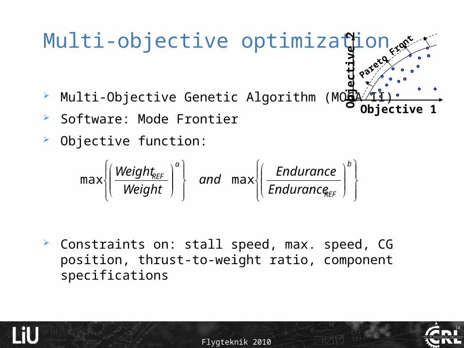
Multi-objective optimization
Multi-Objective Genetic Algorithm (MOGA II)
Software: Mode Frontier
Objective function:
Constraints on: stall speed, max. speed, CG position, thrust-to-weight ratio, component specifications
b
REF
a
REF
Endurance
Enduranceand
Weight
Weightmaxmax
Objective 1
Ob
ject
ive
2
Pareto
Front

Flygteknik 2010
15
Design Framework - Mode Frontier

Flygteknik 2010
16
Optimization Results
Example analysis with real components database
2.8155E-1 3.8155E-1 4.8155E-1
Weight
1.4657E1
2.4657E1
3.4657E1
4.4657E1
5.4657E1
6.4657E1
7.4657E1
En
du
ran
ce
1.6888E4
1.5023E4
1.3159E4
1.1294E4
9.4298E3
7.5652E3
5.7007E3
3.8361E3
1.9716E3
1.0700E2
ID
4147
8748
9035
9466
9520
10008
10278
10424
10681
10888
1213312162
13804
1451414573
14911
15201
15518
15740
1579316377
16386
164431681216840
2.8491E-1 3.8491E-1 4.8491E-1
Weight
1.4505E1
2.4505E1
3.4505E1
4.4505E1
5.4505E1
6.4505E1
7.4505E1
Endura
nce
1.8750E3 1.6669E3 1.4588E3 1.2507E3 1.0426E3 8.3444E2 6.2633E2 4.1822E2 2.1011E2 2.0000E0
ID
1727

Flygteknik 2010
17
Pareto Frontier Designs
Mission Requirements:
Cruise speeed = 70km/h
Stall speed= 35km/h
Payload = 60g video camera
T/W ratio= 0.7
2.8491E-1 3.8491E-1 4.8491E-1
Weight
1.4505E1
2.4505E1
3.4505E1
4.4505E1
5.4505E1
6.4505E1
7.4505E1
En
du
ran
ce
1727

Flygteknik 2010
18
Automated Manufacturing Test using FDM 3D printer: 270mm MAV
Benefits:No ”craftsmanship” is neededGeometric complexity – no influence on costGood accuracy and repeatabilityAllows easy validation
90g 60g

Flygteknik 2010
19
Validation and Flight Testing
Root Chord 208 mm Motor Turnigy C1822Tip Chord 56 mm Battery FlightPower EVO Light 3s350MahWing Span 270 mm Propeller APC 4.5x4.1LE Sweep 38 Deg ESC Turnigy Plush 6ATwist 1 DegNose Length 31 mmWeight 185 g
Geometrical Specs Propulsion System Specs
Predicted Measured Error
Maximum Speed [m/s] 26,4 25,0 5,3%
Endurance (VMax) [min] 6,1 6,0 1,6%
Weight [g] 185 187 1,1%

Flygteknik 2010
20
Conclusions
Automated MAV design has been demonstrated and proven to be realistic. Current modeling is a balance of accuracy and calculation speed. Propulsion
system has highest impact on performance Method can be seen as a stepping stone for improving conceptual design
methods for larger UAVs and manned aircraft.
Key innovations to achieve automated design is: Discrete propulsion system optimization using COTS-components Unique composition of design framework Sequential optimization process with increased model fidelity Usage of Multi-objective optimization Efficient method for internal component placement and balancing 3D printing for fabrication

Flygteknik 2010
21
Future Work
Validation of aerodynamics and propulsion
Flight simulation – Control system design
Increased model accuracy (CFD)?
0,0
20,0
40,0
60,0
80,0
100,0
120,0
4,000 5,000 6,000 7,000 8,000 9,000 10,000 11,000 12,000 13,000 14,000U (V)
P(W
) /
n(rp
m/1
00)
0,00
0,10
0,20
0,30
0,40
0,50
0,60
0,70
0,80
0,90
1,00
Eta
Pin
Put
n
Eta