design catalogue 2017 · · 2017-03-21litecrete precast residential wall panels have been...
TRANSCRIPT
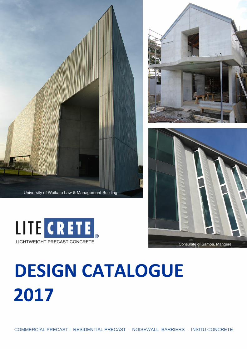
DESIGN CATALOGUE 2017
COMMERCIAL PRECAST ǀ RESIDENTIAL PRECAST ǀ NOISEWALL BARRIERS ǀ INSITU CONCRETE

1 www.litecretesystems.co.nz © Copyright 2017
INTRODUCTION DESCRIPTION & STRUCTURE OF THIS CATALOGUE This information, when used in conjunction with the New Zealand Building Code (NZBC), sets down the construction requirements for the Litecrete lightweight precast concrete system. Section 1: Litecrete Product Range Section 2: Litecrete Lightweight Precast Concrete Properties Section 3: Building Code Requirements and Compliance Section 4: Design Information Section 5: Litecrete system Section 6: Structural Design Data Section 7: Product Evaluation Results Section 8: Residential Construction Section 9: Installation Section 10: External & Internal Finishing Section 11: Commercial Construction Section 12 Sustainable Building Section 13: Construction Details Section 14: Appendix - Architectural Specifications, Material Safety Data Sheet, Transportation Limitations
For further information please contact: Philip Archer Litecrete NZ Limited Mobile: 0275 505 372 Email: [email protected] Updated 5 January 2017

www.litecretesystems.co.nz © Copyright 2017 2
2
1.0 PRODUCT RANGE 1.1 Litecrete Lightweight Precast Concrete System Litecrete is a lightweight precast concrete system developed and manufactured by Wilco Precast Ltd, Papakura. It has been designed to conform to, and comply with, New Zealand Building Codes, practices and construction methods. Litecrete offers insulation, fire resistance and acoustic properties, can be installed rapidly and can be used for a wide range of projects. Litecrete offers the following features and benefits: Large panel sizes Peace and quietness between rooms and between floor levels Safer environment; Litecrete is fire resistant, non-toxic, mould and mildew resistant Design advantages; classic to contemporary; deep reveals around windows, doors Exterior finishes to suit; fine or accented plaster; smooth or textured paint systems Rot-proof, strong, permanent Built-in insulation provided by the pumice aggregate provides a low humidity environment and ensures energy savings; warm in winter, cool in summer 1.2 Standard Surface Finish
Mould face: This is usually the exterior face of the panel and is cast on steel casting beds. F5 finish is the typical specification. Tiny pinholes caused by entrapped air, excess mould release agent, marks on the casting surface and mould release agent staining can be expected. Minerals contained within the pumice aggregate can sometimes cause more surface figuring compared to normal precast panels. Where a blemish-free surface is required, the application of masonry paint or a mineral-based stain is recommended.
Trowelled face: The trowelled face of the panels, usually the internal face, will have a U3 surface finish. The finish will be uniform and provide full cement paste cover to the aggregates. Some trowel marks will be visible and colour and texture variation may be expected, as well as colour variation from batch to batch. Where a uniform colour is required, the application of masonry paint or a mineral-based stain is recommended. “Clear” Concrete Finish: Where a natural concrete look is required, we recommend that a clear, matt finish concrete sealer be applied to Litecrete panel surfaces after installation. There are some other important aspects to this option which must be considered and these are detailed on Page 20.
1.3 Litecrete Residential Wall Panels Litecrete precast residential wall panels have been designed to offer a durable alternative to traditional house construction methods, and for the purposes of complying with the Building Code are classed as an “Alternative Solution”. Litecrete precast panels form an integral wall -- solid, continuous and airtight. Litecrete is manufactured using pumice as an aggregate, which reduces the weight of the concrete yet achieves strength of 12 MPa. The air cells in the pumice provide excellent insulating properties. Litecrete is manufactured under strict quality-controlled factory conditions, delivered to site and rapidly installed. Various thicknesses can be manufactured to order, from a minimum of 150 mm. Panels have fully embedded steel reinforcing. Standard sized panels up to 7-8 metres x 3.5 metres and can be used for single-storey or two-storey applications. Larger panels are possible subject to freight/design parameters. 1.4 Litecrete Commercial Cladding The design, application, engineering, panel sizes and installation requirements for low-rise and high-rise Litecrete commercial projects differ markedly from residential installations. Potential uses are for exterior cladding, sunshades, fins, acoustic or firewalls and façade re-instatements. Standard sized panels up to 7-8 metres x 3.5 metres, subject to freight considerations and design parameters such as window or door opening sizes. Litecrete will typically reduce the deadload on the structure by 50% compared to standard precast concrete. 1.5 Litecrete Firewall System The Litecrete Firewall system consists of Litecrete 150 mm thick solid walls, with tongue and groove vertical joints and also includes a specific proprietary sealant for both the exterior and interior sides of the joints, thereby allowing it to be used in applications where a demonstrated fire performance is required. The fire-rated system can also be used as a complete and finished wall system in its own right. A BRANZ test (FR 3524) using 150 mm thick Litecrete panels achieved a 240-minute fire resistance rating. 1.6 Litecrete Acoustic Wall Systems The Litecrete Acoustic Wall system provides excellent sound insulation and meets the performance requirements of NZBC G6.3.1 for inter-tenancy walls. This approved acoustic system exceeds the Minimum Sound Transmission Class 55 when constructed in accordance with the details contained in this manual. Results of the tests conducted at Auckland Uniservices Acoustic Test Centre by Marshall Day Acoustic Engineers are available on request. Sound-rated wall systems ranging from low STC values - STC 47 - up to STC 60 are available. The bare 150 mm thick wall achieves STC 47; bare 260 mm thick wall achieves STC55.

3 www.litecretesystems.co.nz © Copyright 2017
1.7 Litecrete Motorway Noisewall Barriers Litecrete noisewall barrier panels reduce the sound level by shielding the straight line path of noise from the source to receiver. The received noise level is significantly reduced due to the shielding effect. Using modelling software, acoustic engineers can determine the optimum height, length and placement of Litecrete panels to effectively minimise noise levels. Typically, 150 mm thick Litecrete has been approved and used for as noisewall barriers by Transit NZ.
1.8 Litecrete Insitu Concrete Litecrete is available as an insitu mix and is used particularly where weight is a major consideration. Applications such as screeds over old or new concrete – balcony/roof toppings - streetscape remedial work, etc. It can also be used for insitu concrete house construction. There are limitations on the distance from the batching plant to the construction site. 2.0 PRODUCT PROPERTIES 2.1 Composition Standard concrete is made with cement and heavy aggregates - typically crushed rock. Litecrete uses pumice as an aggregate, which reduces the weight of the concrete yet provides the required strength. The air cells in the pumice provide insulating properties, convenient lightness, and ease of use. The combination of pumice and cement, together with steel reinforcing systems and polypropylene fibre reinforcement, gives Litecrete its unique strength-to-weight ratio. The inclusion of the polypropylene fibres also assists in fire prevention on the basis that, as the concrete is heated by fire, the fibres melt, creating conduits along which water vapour can dissipate, so avoiding a build-up of pressure and preventing spalling from occurring. The image below, from a scanning electron microscope at x50, shows a Litecrete sample from a compression test, with the polypropylene fibre still binding the pumice concrete together. 2.2 Mix Components
Pumice aggregate: 65-75% Si02, 10-20% Ai203.
Cement: HR brand GP General Purpose
Cement (Portland No 65997-15-1).
Plasticiser: Sika ViscoCrete® 5-500.
Polypropylene fibre: monofilament concrete fibre, manufactured to comply with ASTM C-1116.
2.3 Dimensions The advantage of precast concrete is that a variety of sizes can be accommodated. In some instances the complete side wall of a house can be manufactured as one panel. Standard Litecrete residential wall panels are manufactured to a maximum panel size of 7-8 metres x 3.5 metres, subject to design parameters. Commercial panel sizes are tailored to suit the project. 2.4 Mass Litecrete has a cured density of 1550 kg/m³ including the reinforcing. The density at shipping is 1700 kg/m³.

www.litecretesystems.co.nz © Copyright 2017 4
4
3.0 BUILDING CODE REQUIREMENTS The Litecrete Construction System, which is subject to specific engineering design, meets the following performance requirements of the Building Code:
Clause B1 STRUCTURE: Performance B1.3.1, B1.3.2 and B1.3.4 for the relevant conditions as in B1.3.3. a, b, f, g, h, i, j Clause B2 DURABILITY: Performance B2.3.1, 50 years Clause C3 SPREAD OF FIRE: Performance C3.3.5 Clause E2/AS1 EXTERNAL MOISTURE: Performance E2/AS1:3.2, E2/AS1:3.3, E2/AS1:3.6 Clause E3 INTERNAL MOISTURE: Performance E3.3.1 Clause F2 HAZARDOUS BUILDING MATERIALS: Performance F2.3.1 Clause G6 AIR & IMPACT SOUND: Performance G6.3.1 Clause H1 ENERGY EFFICIENCY: Performance H1.3.1, H1.3.2
Clause B1 STRUCTURE Performance requirement B1.3.1 Litecrete Lightweight Precast Concrete Systems are required to withstand the combination of loads they are likely to experience during construction or alteration and throughout their serviceable life. The systems have a low probability of rupturing, becoming unstable, losing equilibrium, or collapsing and have a low probability of causing loss of amenity through undue deformation, vibratory response, degradation or other physical characteristics throughout their serviceable life. Litecrete Lightweight Precast Concrete Systems meet the requirements for loads arising from self-weight, imposed gravity loads, earthquake, wind, fire and human impact. Demonstration of Compliance Litecrete applications are subject to specific engineering design. Typical design and construction details of panel-to-panel, panels and the connection details of the panels to the adjoining structure are shown in Section 13 Construction Details. All reinforcing shall comply with the provisions of AS/NZS 4671; either grade 300 or grade 500. Wall Panel Bracing Units Litecrete 3000 x 1200 x 220 mm thick panels achieve 640 bu’s (University of Auckland In-Plane Test report). Clause B2 DURABILITY Performance requirement B2.3.1 (a) not less than 50 years (b) 15 years and (c) 5 years The NZBC sets durability requirements for building elements depending on the use and the ease of replacement and maintenance. Within the building elements the different components can have different durability requirements. Litecrete exterior wall panels are structural elements and therefore require a durability of not less than 50 years. This applies to the bracing panels and system connection components. Litecrete associated joint sealants, seals, flashings and sealing systems are required to have 15 years’ durability. Demonstration of Compliance 1. History of Pumice Concrete Although lightweight precast pumice concrete is new to the New Zealand construction market, pumice concrete has been used for various structures here for over 100 years. The first documented application was for structural wall elements in Tudor Towers, the former Government Bathhouse in Rotorua, which was built in 1906. Since then proprietary systems have come and gone. Konka Board, a factory-made panel (900 mm x 450 mm) was produced by Bassett & Co of Wanganui from 1914 until the 1950s. It was held in place by patented clips and was used for both internal and external walls. Another pumice-concrete panel for walls and floors, Fabricona, began production in the 1940s but closed down in 1951. Atlas Concrete Ltd in Wellington also manufactured pumice concrete panels successfully for a number of years but widespread acceptance was generally suppressed due to (1) the relative costs of the pumice concrete compared to the standard timber-framed cavity walls and (2) the reluctance of builders to use concrete as they believed it had the propensity to take away a major part of their trade skill. However, of recent times problems such as leaky homes, ongoing timber price rises and the increasing awareness of concrete as an energy efficient building material have gone a long way towards increasing the acceptance of concrete in general, and pumice concrete in particular, as a viable alternative. 2. Lightweight concrete durability The durability of concrete is defined as its ability to resist weathering action, chemical attack, abrasion, or any process of deterioration. The mechanism that can cause premature deterioration resulting in a serviceable life <50 years, is weathering action caused by water.

5 www.litecretesystems.co.nz © Copyright 2017
It is well known that the superior water absorption/desorption characteristics of pumice means that the moisture held in the aggregate is not immediately available for chemical interaction with cement, so is extremely beneficial in maintaining longer periods of curing, resulting in better strength in the final concrete. Auckland Uniservices have tested samples of Litecrete vs 30 MPa normal precast concrete, for water absorption. The test report concluded that Litecrete does not saturate with water to the same extent when compared to 30 MPa concrete. However, to enhance durability where Litecrete is to be used with a raw concrete external finish the panels should be treated with a clear matt finish vapour permeable (breathable) sealer to. As is the case with normal precast, the below-ground area of the Litecrete panels should have a waterproofing membrane applied. The minimum reinforcement cover requirements as per NZS 3101, Section 3, for 25 MPa concrete, is 40mm. Litecrete recommends a minimum 50 mm cover for any steel reinforcement design. 3. Exterior Coatings Exterior coatings (paints/plaster/stain/clear sealant) where specified must be of a vapour-permeable type and comply with the relevant clauses of the NZBC. In all cases the manufacturers’ application and maintenance instructions must be followed, with particular attention given to the following areas: 1. Weathering, flashing and sealing systems at door and window openings, junctions with other materials and any other penetrations
of the exterior envelope. The need for specific flashings will depend on the configuration and design of the detail but are strongly recommended in all circumstances.
2. The ground/ foundation/floor/wall interface. Particular care needs to be given to ensure that minimum distances between ground and floor level, as stated in NZS 3604:2011, are complied with.
3. External plaster systems where specified are installed and cured within the temperature limitations, climatic and curing conditions
set by the manufacturer. The finished external plaster system is sealed and protected from the weather with a vapour-permeable coating system such as Resene X200 or Mapei Elastocolor. Exterior paint systems will require a minimum 5-year durability as part of the system.
Clause C3 SPREAD OF FIRE Performance C3.3.5 The Litecrete Lightweight Precast Concrete System is naturally fire resistant being made from non-combustible materials. Demonstration of Compliance BRANZ test report FR3524 - Fire resistance of a lightweight concrete panel load bearing wall; the 150 mm thick wall achieved a 240-minute fire resistance rating.
Clause E2/AS1 EXTERNAL MOISTURE Performance E2/AS1:3.2, E2/AS/1:3.5, E2/AS1:3.6 Exterior walls shall prevent the penetration of water that could cause undue dampness, or damage to building elements. Concealed spaces and cavities in buildings shall be constructed in a way, which prevents external moisture being transferred and causing condensation and the degradation of building elements. Excess moisture present at the completion of construction shall be capable of being dissipated without permanent damage to building elements. Demonstration of Compliance This Litecrete Lightweight Precast Concrete System catalogue contains a well proven set of typical construction joint, penetration, openings and attachment details that can be used for both residential and commercial construction (see Section 13, Construction Details). The window design details are based on recommendations from the Window Association of New Zealand (WANZ). Because engineers use a varied range of precast attachment details to cope with a diverse range of commercial building designs we cannot cover all of these in this document. However, such design solutions have been used successfully for many years. Auckland Uniservices have tested samples of Litecrete for water absorption and the report shows that when compared to normal concrete, Litecrete does not saturate to the same extent with water (see Auckland Uniservices Report 10646.04). However, to enhance durability, we recommend that a clear matt finish sealant is applied to the external surfaces of natural (raw) Litecrete panels. Exterior Plaster/Paint/Clear Sealant Systems If exterior plaster/paint (coating) and clear sealant systems are used they must comply with the relevant clauses of the NZBC. The combination of pumice concrete and air entrainment used in the manufacture of Litecrete wall panels provides an in-built insulation value. This means that the walls can “breathe”, allowing water vapour (condensation) to move through the wall to the exterior of the building. Therefore, where paint, plaster or clear sealant systems are used, they should be vapour-permeable. We recommend systems that have a BRANZ Appraisal and/or meet the NZBC requirements.

www.litecretesystems.co.nz © Copyright 2017 6
6
Maintenance External coating systems must be maintained in accordance with the respective manufacturer’s instructions and all damage repaired promptly to ensure the ongoing weathertight properties of the coating systems. In addition to these system-specific requirements, the following general maintenance procedures must also be implemented: Any dirt accumulation or organic growth that may occur should be regularly removed from the external surface by cleaning with warm water and detergent and a soft bristled broom. Solvent-based cleaners must not be used. The external cladding system should be checked yearly for damage to the system itself, deterioration of seals and possible water entry at junctions and joints. Any damage to the coatings, which does occur, must be repaired in accordance with the manufacturer’s instructions. Clause E3 INTERNAL MOISTURE Performance E3.3.1 The Litecrete Lightweight Precast Concrete System must take into consideration installation details for maintaining correct moisture levels in buildings where normal occupancy levels exist and adequate ventilation is provided (e.g. complying with NZBC E3/AS1 Paragraph 1.2) ensuring the performance requirements of NZBC E3.3.1 will be met. Correct thermal design and installation must be strictly followed to meet the minimum R-values in NZBC Acceptable Solution E3/AS1 Paragraph 1.1.1 (b) solid construction. Demonstration of Compliance The Litecrete Lightweight Precast Concrete System has test a report from Curtin University stating an achieved R Value of R0.6 for a 150 mm thick panel. The introduction of revised H1 in 2009 revised the R-value requirements for Litecrete: Climate Zone 1, R-value of R0.8 This is achieved with 220 mm thick panels (“Solid Construction – excluding timber”) Climate Zone 2, R-value of R1.0 This is achieved with 280 mm thick panels (“Solid Construction – excluding timber”). Climate Zone 3, R-value of R1.2 This is achieved with 330 mm thick panels (“Solid Construction – excluding timber”). Auckland Uniservices have tested samples of Litecrete for water absorption and the report shows that when compared to normal 30 MPa concrete, Litecrete does not saturate to the same extent with water.
Clause F2 HAZARDOUS BUILDING MATERIALS Performance F2.3.1. The materials and components used in the manufacture and site construction of Litecrete comply with NZS 3604:2011, which is an NZBC referenced Compliance Document. The Litecrete Lightweight Precast Concrete System meets this requirement and will not present a health hazard to people. Demonstration of Compliance A Material Safety Data Sheet is attached in Appendix.
Clause G6 AIRBORNE AND IMPACT SOUND Performance G6.3.1 The sound transmission class of walls, floor and ceilings shall not be less than STC 55. Demonstration of Compliance The Litecrete Lightweight Precast Concrete System has acoustic testing on 150 mm thick wall panels strapped on one face, insulated and an additional layer of 13 mm plasterboard applied. It achieved an STC 60 rating. (See Auckland Uni Acoustic Report T0607-3).

7 www.litecretesystems.co.nz © Copyright 2017
Clause H1 ENERGY EFFICIENCY & INTERNAL MOISTURE Performance H1.3.1 & H1.3.2 Buildings constructed using the Litecrete lightweight precast concrete system, are able to meet the performance requirements for energy efficiency as required by NZBC Clause H1.3.1 and H1.3.2. It should be noted that compliance with NZBC H1 will also include many factors resulting from the design of the building, all of which have an influence on the energy efficiency of a building. The excellent thermal insulation properties of the Litecrete wall panel system ensures that when used with both an adequate level of ventilation and an appropriate level of ceiling / roof insulation, Litecrete will satisfy the internal moisture provisions of NZBC Clause E3.3.1. Appropriate or adequate levels of ventilation and insulation are provided in the NZBC Acceptable Solution E3/AS1. NZBC Acceptable Solution E3/AS1 Paragraph 1.1.1(b) requires a current minimum wall R-value. Higher levels are required to meet the new energy efficiency requirements of NZBC Clause H1. Demonstration of Compliance A Test Report from Curtin University shows that Litecrete achieved an R-value of R0.6 for a 150 mm thick panel.
NZBC Clause H1 – Energy Efficiency to NZS 4218:2009 The Building Code Clause H1 Energy Efficiency is defined in New Zealand Standard 4218:2009. Residential construction categories are changed to: 1. Non-solid Construction; eg (timber framing with various types of exterior cladding), or 2. Solid Timber Walls (such as “Lockwood” type system), or 3. Solid Construction – excluding timber (concrete or masonry) Litecrete falls under the definition of Solid Construction – excluding timber. Because of the benefits of the thermal mass of the concrete (its ability to absorb and slowly dissipate energy) this category has been allocated a dispensation in R-value requirements compared to Categories 1 and 2. Following are Category 3 requirements for the various climate zones:
Climate Zone
Min R-values
Litecrete Building Code compliance solution
Zone 1: Northland, Auckland and Coromandel, Option 1 (a)
R0.8
Solid Construction – excluding timber 220 mm thick panels (R0.8)
Zone 2: Rest of North Island except Volcanic Plateau, Option 2 (a)
R1.0
Solid Construction – excluding timber 280 mm thick panels (R1.0)
Zone 3: South Island and Volcanic Plateau, Option 3 (a)
R1.2
Solid Construction – excluding timber 330 mm thick panels (R1.2)
The Standard provides for three methods of compliance: 1. The Schedule Method shall only be used where: (a) The glazing area is 30% or less of the total wall area; (b) The combined area of glazing on the east, south and west-facing walls is 30% or less of the combined total area of these walls; (c) The skylight area is no more than 1.2 m² or 1.2% of the total roof area (whichever is the greater); (d) The total area of decorative glazing and louvers is 3 m² or less 2. The Calculation Method shall only be used where: The glazing area is 40% or less of the total wall area 3. The Modelling Method shall only be used where: The glazing area is more than 40% of the total wall area * Note that installing insulation on the internal face of normal precast concrete or masonry negates the benefits of thermal mass.

www.litecretesystems.co.nz © Copyright 2017 8
8
External Residential Litecrete Wall in Climate Zone 1
Litecrete wall thickness of 220 mm complies with Building Code insulation requirements - “Solid Construction excluding Timber” - with an R-value of R0.8
Contemporary Matakana house with vertical rough-sawn timber finish and rebates

9 www.litecretesystems.co.nz © Copyright 2017
4.0 Design Information All Litecrete applications are subject to specific engineering design by a registered structural engineer (not by Litecrete) prior to lodging a Building Consent application. 4.1 Residential Construction Following is the design information, detailing and construction practices that can be used for Litecrete wall and mid-floor systems for buildings within the following limitations: 4.1.1 Single-Storey Residential Dwellings:
Walls, ground floor connections, mid-floors and roof connections are constructed in accordance with the design details in the Litecrete Lightweight Precast Concrete Manual. Ground floor slab, internal timber walls and roof framing are constructed in accordance with NZS 3604:2011.
4.1.2 Two-Storey Residential Dwellings: Either 2-storey high Litecrete wall panels or Litecrete panels for the ground floor installed in accordance with the manufacturer’s recommendations, with light timber frame walls, constructed in accordance with NZS 3604:2011, for the upper storey. Suspended timber floor shall be of light timber construction complying with the relevant requirements of NZS 3604:2011. Roof shall be of light timber construction complying with the relevant requirements of NZS 3604:2011.
4.1.3 A maximum inter-storey height of 3.2m. 4.1.4 A maximum roof plane slope of 45º to the horizontal. 4.1.5 Buildings are to be category IV buildings as described in table 2.3.1 of NZS 4203. 4.1.6 A maximum design wind speed (V’s) for the building of VH (very high), as defined in section 5.3 of NZS 3604:2011. 4.1.7 Suspended timber floors and roofs shall be of light timber construction complying with the relevant requirements of
NZS 3604:2011. 4.1.8 Maximum suspended floor imposed live load of 1.5 kPa or a concentrated live load of 1.8 kN. Site requirements are as per NZS 3604:2011, Section 3. Each part of the building or structure shall be within the limitations stated in the relevant section or tables of this manual. 4.2 Commercial Construction Litecrete wall panels can be used in other structures, which are subject to specific engineering design, including multi-story buildings. Such structures are designed / engineered by a registered structural engineer, not by Litecrete. Most connections and attachments can be used for both residential and commercial construction, others may be design specific. 4.3 Reinforcing Requirements All reinforcing shall comply with the provisions of AS/NZS 4671. Typical reinforcing configuration for a residential panel: D12 @ 300 mm centres each way. Note that the Code requirement for precast concrete panels over 200 mm thick is for two layers of reinforcing

www.litecretesystems.co.nz © Copyright 2017 10
10
5.0 Litecrete System 5.1 General 5.1.1 Litecrete wall panels: steel reinforcing bars fully embedded in the specified Litecrete lightweight precast concrete. Conduits for services can be set into the panel during the casting process, or trenched into the surface on site, using a diamond-tipped router. Paint or plaster finishes can be applied, if required to the exterior face and a variety of render-set finishes/paint systems are available for internal walls. These exterior and interior finishing systems must be vapour-permeable. Natural (“clear”) concrete finish is optional (see Page 25). Buildings designed with Litecrete panels are subject to specific engineering design. 5.1.2 Fire/acoustic inter-tenancy walls for apartment and other residential buildings, eg hospitals, hotels, etc. Litecrete 150 mm achieves a 240-minute fire resistance rating (refer BRANZ Fire Resistance Test FR 3524) and offers acoustic systems that achieves up to STC 60. 5.1.3 Litecrete exterior cladding panels for high-rise construction. The system is based on panels with a typically 150 mm asymmetrical thickness, although thicker panels can be supplied if required. They can be shipped as individual panels or as unitised (factory-built) modules, delivered to site, craned up and attached to the sub-structure of the building. Litecrete can also be used for lightweight concrete balustrades, fins and other applications. 5.2 Supply of Litecrete Panels Once it has been decided to use Litecrete in a project the architect/designer will consult an engineer, who will design the foundation and structural requirements for the project. The architect/builder will usually send drawings, with the engineer’s designs/calculations, so that Litecrete (Wilco Precast) can supply a firm quotation. Further to acceptance of the quotation, Litecrete produce workshop drawings detailing the panel design. These drawings are then signed off by the architect/engineer before manufacture of the panels can begin. Prior to delivery of the panels the builder arranges a crane for installation. Panels for a simple house design could be installed in one to two days. 5.3 Durability Litecrete does not rot, or harbour mould or mildew. When used and installed in accordance with the limitations and instructions of the manufacturer, the specifically designed components of the Litecrete wall panel system can be expected to meet the New Zealand Building Code durability requirement of 50 years, provided the Litecrete wall panels are installed and finished as recommended and all protective linings and coating systems, where applied, are correctly maintained. Associated sealants and flashing systems are required to have 15 years durability. 5.4 Thermal Properties Litecrete wall panels painted and/or plastered internally and externally have a thermal resistance of 0.12 +/- 0.6 m²KW-¹. Refer to NZBC, Building Code Requirements, Section 3, Clause H1 Energy Efficiency & Internal Moisture. 5.5 External Moisture Auckland Uniservices test report (to ASTM C1585-04) dated 30 October 2006 shows that Litecrete has proven to have a superior secondary water absorption rate compared to 30 MPa normal precast concrete. However, to enhance durability Litecrete panels should have a clear matt finish sealer applied to the external face after installation. 5.6 Internal Moisture The excellent thermal insulation properties of the Litecrete wall panel system ensures that when used with both an adequate level of ventilation and an appropriate level of ceiling/roof insulation, Litecrete will satisfy the internal moisture provisions of NZBC Clause E3.3.1. Appropriate or adequate levels of ventilation and insulation are provided in the NZBC Acceptable Solution E3/AS1. 5.7 Energy Efficiency Buildings constructed using the Litecrete lightweight precast concrete system can meet the performance requirements for energy efficiency as required by NZBC Clause H1.3.1 and H1.3.2. It should be noted that compliance with NZBC H1 would also include many other factors resulting from the design of the building, all of which can effect the energy efficiency of a building. 5.8 Retaining Walls Typical precast concrete retaining walls have minimum strength of 25 MPa. However, 12 MPa Litecrete can be designed by the structural engineer for minimal retaining purposes but must be appropriately tanked. 5.9 Fire 5.9.1 General Properties
Litecrete is fire-resistant to 240/240/240 (refer BRANZ Report FR 3524). 5.9.2 Control of Internal Fire and Smoke Spread
Internal surface finish requirements are as per Table 6.2 of NZBC Acceptable Solution C/AS1.

11 www.litecretesystems.co.nz © Copyright 2017
5.9.3 Control of External Fire Spread
External walls that comply with the external wall provisions of Clause 7.11 of NZBC Acceptable Solutions C/AS1 will meet the performance provision of NZBC Clause C3.3.5. Litecrete lightweight precast wall panels will meet the requirements for a type A Heat Release rate in applications covered by Table 7.5 of NZBC Acceptable Solutions C/AS1. Litecrete 150 wall panels will meet the performance provision of NZBC Clause C3.3.5 when restricted to: Single storey buildings 1m or more from the boundary for all purpose groups. Buildings up to 7m high, 1m or more from the boundary, for all-purpose groups other than SC and SD. Fully sprinkled buildings up to 25m high, 1m or more from the boundary for all-purpose groups other than SC, SD,
SA and SR. Buildings containing purpose group SH, and with a building height less than 10m and located 1m or more from the boundary. 5.10 Acoustics Litecrete wall panels provide excellent sound insulation and meet the performance requirements of NZBC G6.3.1 for inter-tenancy walls. The approved acoustic system achieved Sound Transmission Class (STC) 60 when constructed in accordance with the method described in Litecrete Acoustic Systems. See details IW1 (STC47), IW2 (STC55) and IW3 STC 60). 5.11 Cast-in Surface Textures Litecrete can offer cast-in surface textures and rebates similar to standard precast concrete. These can range from simple diagonal and vertical lines up to intricate patterns using rubber formliners. Rough-sawn timber textures are currently in vogue, however there is panel width limitations due to the extra suction experienced when de-moulding the panels off the timber planks. 5.11 Electrical Cabling/Conduits Conduits for electrical and other wiring services can be cast-in during panel manufacture. However, it is relatively simple to cut a 40 mm deep chase into the Litecrete wall panels to provide extra plumbing/electrical channels. This can be achieved using an electrical router with a masonry cutter or a diamond-tipped tile saw. Note that the plasticiser in PVC-sheathed electrical cables can migrate over time causing deterioration, therefore cables must be contained within a plastic conduit if embedded in the Litecrete wall. The conduit must be fixed at regular centres to the bottom of the chase before being plastered over.
Litecrete cladding panels with random width vertical rebates, being installed on University of Waikato Law & Management Building

www.litecretesystems.co.nz © Copyright 2017 12
12
6.0 Structural Design 6.1 Definitions Light roof A roof and ceiling (structure, cladding, lining, insulation, services) having a mass not exceeding 20 kg/m2. Heavy roof A roof and ceiling (structure, cladding, lining, insulation, services) having a mass not exceeding 60 kg/m2. Light wall cladding An external wall having a mass not exceeding 50 kg/m2. Internal timber frame partitions: An internal partition having a mass not exceeding 30 kg/m2. Lintel or floor beam span Span of opening between concrete. Suspended Concrete Floor A specifically designed concrete floor system including super-imposed dead loads with a mass not exceeding 490kg/m2. Sealants (Joints) Sealants approved for joint use in Litecrete lightweight precast concrete system’s construction details are: Sika Construction AP; Sika AT Facade. 6.2 Structure Loads from other parts of the building structure and fixtures must be transferred directly to the reinforced concrete walls. Structural connections for roofs and floors and lateral support of the tops of walls must be designed appropriately to resist the imposed loads. Walls are to be adequately anchored to floors, roofs, columns, pilasters, buttresses and intersecting walls. 6.3 Wall Panel Bracing Units Litecrete 2400x 1200 x 150 mm panels achieve 400 bu’s (Opus International report). 6.4 Bracing Design Assumptions and Philosophy We have assumed an approximately even distribution of bracing walls with nominated centres each way. Buildings, which are heavily braced on one side and lightly braced on the other side, can suffer damage through tortional movement under wind or earthquake forces. Bracing walls should be located as close as possible to the outside corners of the building. If there is any doubt as to the lateral stability of the structure a structural engineer should be consulted. 6.5 Structural Diaphragms For bracing line systems as defined by NZS 3604:2011 Litecrete walls must be connected to a structural diaphragm. The structural diaphragm provides part of the system for spanning lateral earthquake and wind loads to adjacent supporting systems. Specifically designed concrete floors may also be used as structural diaphragms. The structural diaphragm must comply with NZS 3604:2011, floor diaphragms in accordance with clause 7.3 and ceiling diaphragms in accordance with clause 13.5. 6.6 General Single-storey buildings designed with Litecrete Lightweight Precast Concrete shall consist of: 6.1.1 Foundations as designed by the engineer. 6.1.2 Ground floor must be concrete slab-on-grade constructed in accordance with Clause E11 of NZS 3604:2011, except the
minimum thickness shall be 100mm. The ground floor slab shall be connected to the walls as shown in details D(3)2 Litecrete Panel/Floor Slab Connection and D(3)3 Litecrete Panel/Floor Slab Connection.
6.1.3 External walls shall be Litecrete solid walls to specified thickness, as detailed in the Litecrete Lightweight Precast Concrete Manual. The bottom storey of two-storey buildings must have a minimum wall thickness of 220/180 mm. Upper walls shall be no thicker than the wall below.
6.1.4 Internal walls shall be either Litecrete 150 mm thick solid walls to specified thickness or timber framed internal walls constructed in accordance with NZS 3604:2011. Internal to External wall connections shall be in accordance with detail D9 Litecrete Wall/Timber Frame Connection
6.1.5 The roof shall be timber-framed and constructed in accordance with NZS 3604:2011. The connection of the roof to Litecrete wall panels shall be in accordance with details D4 Litecrete Wall/Roof Connection, D11 Parapet/Wall, D12 Flush Fascia, D13 Wall/Roof Junction Apron Flashing and D14 Gutter/Wall Junction.

13 www.litecretesystems.co.nz © Copyright 2017
6.1.6 Two-storey buildings shall consist of the above clauses 1 to 5 plus the following: (a) Suspended first floors shall be timber floors in accordance with NZS 3604:2011. The connections of suspended timber floors
to Litecrete 220 /150 mm Solid walls must comply with details D8 Litecrete Wall/Mid-floor Connection. (b) First-storey walls shall be Litecrete Solid walls, no thicker than the wall below, or timber walls in accordance with NZS
3604:2011. First floor internal Litecrete 150 mm solid walls must be directly supported by Litecrete minimum 150 mm solid walls below. Suspended first floors supporting Litecrete Solid walls, or load bearing walls, must be specifically designed.
(c) Building lateral stability shall be checked in accordance with NZS 3604:2011 except that bracing units required under earthquake, provided by Litecrete 220 mm thick solid walls, are 640 BUs for a 3000 x 1200 mm panel, based upon the recommended Litecrete panel/foundation connections.
6.7 Minimum Reinforcement Litecrete 150 mm thick wall panels, 1 layer of D12 reinforcing at 300 mm centres each way; 220 mm walls, two layers of D12 reinforcing @ 300 mm centres each way.
Grade 300 reinforcing Grade 500 reinforcing Vertical D12 @ 300 mm centres H12 @ 300 mm centres Horizontal D12 @ 300 mm centres H12 @ 300 mm centres
6.8 Higher Strength Litecrete Where R-values are not a consideration, Litecrete is able to be manufactured in the range of 16 to 20 MPa with a corresponding increase in density. This could be useful to structural engineers for designing building components such as balcony panels or for insitu toppings on metal tray flooring systems. Please contact us for further information.
Prefabricated timber midfloor being craned into position while the mobile crane is still on sit

www.litecretesystems.co.nz © Copyright 2017 14
14
7.0 Product Performance Test Results
Test standard Criteria Results
FIRE PERFORMANCE:
Fire Spread and Burning Maximum temp rise of 36C° above 750C° 0
Smoke Development ASTM E84 No flaming 0
Smoke Generation ASTM D136 Weight loss not to exceed 20% 0
Combustibility CAN/ULC-S114-M80 Material classified as Non Combustible
Fire Resistance Rating AS 1530.4 1997 Resistance to heat; refer BRANZFire Resistance Test FR 3524
FRR 240/240/240
PHYSICAL PROPERTIES:
Sorptivity - Initial Rate of Water Absorption ASTM C1585.04 mm/sec^0.5 Litecrete = 0.0107 @ 12Mpa;
normal concrete = 0.0215 @ 30MPa
Vapour Flow Resistance N/A 30 -100 (GN.s/kg.m)
Thermal Conductivity (k) Value
Thermal resistance (R) Value
AS/NZS 4859.1 NZS 4218:2009
0.32 +/- 0.003 Wm-¹K-¹ 0.16 +/- 0.06 m² KW-¹ (for 50 mm)
Tests conducted at Curtin University, Perth: ASTM C-177, ASTM C-653, ASTM C-167. Meets Code requirements (solid construction) for Climate Zone 1: 220 mm thick = R0.8
Environ. Compatibility
EPA M 1311
No pollution
No detrimental effects.
Mould and Mildew MIL STD 810E Susceptibility Does not support fungal growth. Rated: 0
Modulus of Elasticity ASTM-C469-02 N/A 4580 MPa (28 days)
Modulus of Rupture NZS 3112 P2 N/A 1.45 MPa (28 days)
Coefficient of Thermal Exp.
ASTM C531 N/A 5.51 (AVE) x 10-6/ F°
Shrinkage
NZS 3151:1974 N/A < 1000 με (microstrains)
Compressive Strength NZS 3151:1974 N/A > 10 MPa (28 days)
Density NZS 3112 P3 N/A
1700 kg/m³ at delivery min 14 days 1550 kg/m³ (28 days) reinforced 1450 kg/m³ (28 days) un-reinforced
Tensile Strength NZS 3112 P2 N/A 1.3 MPa (28 days)
Bracing Units Uni of Auckland 3000x1200x220 mm panel = 640 BU’s
ACOUSTIC PERFORM Specification STC Class Fire Resistance Test Criteria
150 wall panels strapped/ lined 260 mm thick panel
STC 60 STC 55
240/240/240 240/240/240
ISO 140 Part 3 ISO 140 Part 3

15 www.litecretesystems.co.nz © Copyright 2017
8.0 Residential Construction 8.1 Health & Safety Act 1992 The principle objects of the Health & Safety Employment Act 1992 (HSE Act) are to prevent harm to employees at work. To achieve this, the Act imposes duties on employers, employees, principals and others to promote excellent health and safety management by employers. It also provides for the making of regulations and codes of practice. The “Approved Code of Practice for the Safe Handling, Transportation and Erection of Precast Concrete” was developed by construction industry representatives to ensure safe work practices are promoted and become standardised normal work practices in precast factories and on building sites. All Litecrete panels should be installed by persons familiar with precast concrete installation. All of the major craneage companies offer skilled precast concrete riggers as part of their installation service. It is also important that the builder is made familiar with the construction procedures detailed below. Full guidance is available from Litecrete. 8.2 Handling and Storage As with regular precast concrete, care must be taken with Litecrete panels to protect edges and corners from damage during shipping, craneage and placement. For construction efficiency precast concrete products are usually installed as soon as they are delivered to site. If for some reason the Litecrete panels are to be stored on site they must be placed vertically on A-frames with a resilient type of dunnage (strips of carpet, etc) placed between the panels to protect the panel face. Do not store the panels horizontally in a stack. 8.3 Delivery Access to the site. Check that the site has appropriate access for a truck/truck and trailer unit and that the ground has sufficient stability to support the weight. 8.4 Craneage Cranes are one of the most expensive pieces of equipment used during the installation of Litecrete panels. To minimise this cost it is important to plan ahead for the optimum crane size needed and time the unit is on site. Considerations: 1. The load. Litecrete will supply weight and load dimensions well in advance of panel manufacture so that planning can start early. 2. Proximity of the crane to the lift load. The capacity of the crane is determined by the distance the load is from the centre of rotation. 3. Obstacles which the crane may incur. Power lines, trees and buildings can all impact on the operation of the crane. 4. Ground conditions. Ensure the ground area is big enough to support the weight of the crane when being positioned and working. 5. Impact of crane on the general public. If the operation results in extra traffic control or requires loads being lifted over roadways or
other property then permission from the appropriate authority will be required. 8.5 Lifting Edge lifting is the predominant method used with Litecrete panels. This ensures the panel is vertical for placement over starter bars or other connections; allows panels to be able to be placed close to adjacent structures and also leaves the face of the panel untouched. Because of flexural stresses induced in edge lifting of the panels the maximum residential panel size, with a standard smooth (F5) finish, is approximately 7-8 metres x 3.5 metres, subject to design parameters such as window/door openings. Because of design constraints there may occasionally be the necessity to use face lifters, however these are used as a last resort and in consultation with the customer. 8.6 Horizontal Weather Joints When lifting panels or lintels which have a staggered horizontal weather joint, the lifting shackles can cause damage to the joint upstands. To mitigate this problem the standard precast method is to cast-in polystyrene block-outs into the upstands, within the area of the lifting eyes, so that the lifting shackle is free to move without breaking out the concrete. Photo at right shows a horizontal weather joint where the polystyrene block-out has been removed from the joint upstand to expose the lifting eye. After panel installation the upstand is remediated to restore the weatherproofing integrity of the joint.

www.litecretesystems.co.nz © Copyright 2017 16
16
8.7 Propping Props are used to temporarily support the precast panels until permanent fixing are made. Planning the placement of the props is important as, although they are in place for a relatively short period of time, they take up a significant amount of room and can affect other site works. Typically, external walls are propped from the inside panel face back to the existing floor slab. However, if the construction design requires the walls to sit on footings with the floor slab being poured between the walls later, then the panels will require propping from the exterior face and attached to “dead men” positioned in the ground outside of the floor area, as shown in the photo at right. It is
recommend that M16 threaded propping inserts are cast in to the inside panel face of the panels during
manufacture. Two props are required for each single-storey panel, usually at the 2-metre height. Four props are required for a two-storey panel;
typically two at 2 metres high and two at 4-5 metres high. Photo (left) shows a Reid TIM threaded insert used for propping. A reinforcing bar goes through the hole near the base of the insert. The open end of the insert is set about 3mm below the panel surface and can be covered over after use. Props are also available that have a G-clamp attachment which fit over the top of the panels, removing the need for cast-in propping inserts.

17 www.litecretesystems.co.nz © Copyright 2017
9.0 Installation There are two typical methods of installing single-storey and two-storey Litecrete wall panels in conjunction with concrete floor slabs: Option 1: Panels sit in a rebate in the floor slab and are attached using Drossbach tubes. The wall panels are manufactured with cast-in 40 mm diameter Drossbach tubes, 800-900 mm high, typically at 600 mm (design by structural engineer). These tubes fit over D12 starter bars which have previously been cast-in to a 230 mm wide x 50 mm deep perimeter rebate when the floor slab was poured, prior to the panels arriving on site. See detail D(3)2 Panel/Floor Slab Connection. Once the panels are installed and properly aligned the tubes are filled with epoxy grout. The grout holes are plastered over after filling. Option 2: Panels sit on concrete footings below the floor level, prior to the floor slab being poured. The Litecrete wall panels are manufactured with one or two rows of cast-in Reid brand RB12ti inserts at the bottom of the panel, at centres as designed by the engineer. The panels are positioned on concrete footings, Reid brand RB12 starters are screwed into the inserts and the concrete floor slab is poured. See detail D(3)3 Panel/Floor Slab Connection. While single-storey walls are usually trucked standing up, panels over 3 metres high are delivered sitting on their long edge and require pitching to the vertical during the lifting process using rollers attached to the crane boom.
9.1 Installation using Drossbach Tubes 9.1.1 The floor slab is poured with a 20 mm deep rebate set around the perimeter slightly wider than the specified width of the panel. Starters are cast-in to the perimeter rebate at nominated centres. The base of the rebate must be level to within +/- 5mm in 5m. 9.1.2 Before beginning panel installation, usually well before the delivery truck arrives, mark chalk lines around the perimeter of the floor slab rebate for correct alignment of the panels. Also, mark chalk lines for the internal Litecrete walls, if applicable. Spray chalk lines with clear polyurethane so that they do not scuff or wash off. Perimeter levels should be determined and shims placed prior panel installation. The first panel is usually installed at a corner furthest away from the crane. 9.1.3 Position the panel correctly on the shims, with the inside edge of the panel sitting on the chalk line and the outside panel edge flush with the outer edge of the foundation.
9.1.4 Panels are manufactured with cast-in Drossbach tubes (which are typically 3 x diameter of the starter bars) at nominated centres. These tubes fit over the starter bars, which are cast into the slab and extend 600 mm above the slab.
9.1.5 Panels are lifted into position, ensuring the starter bars in the slab are guided into the Drossbach tubes in the panel. See detail D(3)2 Panel/Floor Slab Connection. 9.1.6 Attach adjustable props to upright panel with a threaded bolt attached to the cast-in inserts on the panel face and to the floor slab using Trubolts. If the floor slab is to have a polished surface, props should be attached to the external panel face and secured to “dead men” in the ground outside the perimeter of the floor slab. Adjust props until panel is plumb. Epoxy grout is gravity-fed into the tubes through grout holes after the panels are fully aligned. Apply same procedure to the other external wall panels, working progressively around foundation perimeter
9.1.7 Ensure that nominal 12 mm vertical gaps are left between each panel. Install lintels, if necessary.
9.1.8 When the timber top plates are in place, weld plates are secured and the panel joints are sealed both sides, the props can be removed. Plaster grout holes.

www.litecretesystems.co.nz © Copyright 2017 18
18
9.2 Installation using Reid Screw-In Starter Bars 9.2.1 Footings are poured to engineer’s design to support the Litecrete
panels, nominally 400 mm below the floor level. 9.2.2 Levels for the footings should be determined and shims placed in
position prior to the panels being installed. 9.2.3 Lift panel and position in place on top of the footings. Align panel
and attach adjustable props with a threaded bolt attached to the cast-in inserts on the internal/external panel face and secure to (a) “dead men” in the ground outside the perimeter of the floor slab or (b) prop off other panels already secured.
9.2.4 Adjust props until panel is plumb. Apply same procedure to the other external wall panels, working progressively around the foundation perimeter. See detail D(3)3 Panel/Floor Slab Connection. Props should not obstruct the pouring of the floor slab.
9.2.5 Ensure that nominal 12 mm vertical gaps are left between each panel. Screw RB12 starters into inserts at the bottom of the panels. The panels are now ready for pouring of the floor slab. Photo (above) shows panel with a row of cast-in inserts prior to Reidbars being fitted and the floor slab being poured.
9.2.6 When the timber top plates are in place and weld plates are secured the props can be removed.
9.3 Installing Litecrete Panels on top of Retaining Walls Litecrete panels can be stacked on top of standard precast or masonry retaining walls. A typical connection is shown in detail D3(4) Panel to Masonry Connection. 9.4 Installing Suspended First Floor Walls Some houses are designed with first storey Litecrete walls inset from the vertical line of the ground floor walls. A steel beam is required to support the weight of the Litecrete, as shown in detail D17 Suspended First Floor Wall Panel Installation. 9.5 Installing Internal Litecrete Walls (if applicable) As Litecrete internal wall panels are not required to be insulated, a 150 mm panel thickness is suitable. The panels can be installed using either Drossbach tubes – as for external walls; see detail D3(7) Typical Internal Wall/Floor Slab Connection, or sitting on purpose-built footings in the ground prior to the floor slab being poured, see detail D3(6) Typical Internal Wall/Floor Slab Connection. In detail D3(7) the starter bars may be (a) cast-in to the floor slab when it is poured prior, or (b) installed by drilling into the slab using Chemset adhesive, 24 hours prior to panel arrival. 9.6 Installing Weatherboards Designer will sometimes specify weatherboards as a feature, maybe on a particular elevation, to be fixed over Litecrete panels. For this application we can cast-in vertical H3 treated timber fillets at 600 mm centres which provide fixing for horizontal battens to which the weatherboards are nailed (see detail D23 Cast-in Timber Fillet for Weatherboard Attachment). 9.7 Supplementary External Cladding Additional exterior cladding systems, such as brick or stone veneer, can be attached to Litecrete exterior wall panels to create feature walls. Such systems must be fit for purpose and must comply with the relevant provisions of the New Zealand Building Code. In all cases the manufacturers’ installation, application and maintenance instructions must be followed. 9.8 Litecrete/Weatherboard Transition Stone veneer adhesive-fixed to Litecrete panels Vertical connection showing typical weatherboards butting up to Litecrete. See detail D10(1) Panel to Weatherboard Connection.

19 www.litecretesystems.co.nz © Copyright 2017
9.9 Litecrete/Fibre-cement Transition Vertical connection showing fibre-cement panels butting up to Litecrete. See detail D10(2) Panel to Fibre-cement Board Connection. 9.10 External Plant-Ons There are proprietary products available, which can be attached to the exterior surfaces of Litecrete walls to replicate classic architectural styles with features such as windowsills, quoins, cornices and mouldings. These can be manufactured from lightweight concrete, expanded polystyrene or plaster and attached according to manufactures’ recommendations (see www.accumen.co.nz). 9.11 Timber/Ply Mid-floor Installation Attach continuous ex 200 x 50 timber joists to wall using Ramset M12 Chemset Anchors at 800 mm centres. See detail D8 Litecrete Wall/Timber Floor Connection. 9.12 Insitu Concrete Mid-floor Installation Attach continuous steel supporting bracket to wall, to engineer’s design, using Ramset M16 Chemset Anchors at centres as specified by the engineer. For an example of an insitu concrete system see detail D8A Litecrete Wall/Insitu Concrete (Metal Tray System) Floor Connection.
Photo shows “rib and infill” midfloor system prior to pouring insitu concrete topping. Reid starter bars have been screwed in to threaded inserts (shown on left) which were cast-in during panel manufacture. When the topping is poured the bars will tie the walls into the floor.
9.13 Wall Panel/Floor/Deck Connection See detail D3(5) Typical Wall Panel/Floor/Deck Connection. 9.14 Door and Window Openings Litecrete wall panels will have openings for windows and doors cast-in during manufacture. A weatherstrip is created at the window head and a sloping sill at the bottom (see detail D5 Litecrete Window Details). Residential windows are installed as per recommendations of the Window Manufacturers’ Association with regard to precast concrete (see detail D6 Litecrete Window Installation - single glazing and detail D6(1) Window Installation - double glazing). 9.15 Ventilation Grilles Where a suspended ground floor is designed, say 600 mm above the ground level, the cavity space underneath requires ventilation. Cast-in openings can be provided through the Litecrete panels for the installation of proprietary concrete or metal vermin-proof grilles (see detail D23 Typical Ventilation Grille Opening). 9.16 Internal timber-framed walls Internal timber frame walls adjoining Litecrete exterior or interior wall panels are connected by fixing the vertical end stud against the Litecrete wall panel using chemical anchors (see detail D9 Litecrete Wall/Timber Frame Connection).
www.litecretesystems.co.nz © Copyright 2017 20
20
9.17 Parapet Wall and Flush Fascia Details See details D11 Litecrete Parapet Wall and detail D12 Litecrete Flush Fascia 9.18 Wall/Roof (Apron Flashing) See detail D13 Litecrete Wall/Roof Junction. 9.19 Gutter/Wall Junction See detail D14 Litecrete Gutter/Wall Junction. 9.20 Meter Box Installation See detail D15 Litecrete Meter box Installation. 9.21 Attaching Top Plates Fixings for all structural and non-structural fittings, where applicable, should be embedded in the Litecrete panels during manufacture. Threaded rods for the attachment of a 50 mm thick timber top plate (if required) should extend 75 mm out of the top of the panel (see detail D4 Litecrete Wall/Roof Connection). 9.22 Services and Wall Penetrations In some instances through-services such as plumbing and electrical, are required to penetrate through Litecrete panels. The advantage of precast panels is that openings can cast in at the time of manufacture. For smaller service holes the Litecrete panels can be easily drilled out on site. Care should be taken when drilling to avoid hitting reinforcing bars. Note that the maximum allowable non-specific dimension of such openings is 400 mm x 400 mm. See detail D16 Litecrete Pipe Penetrations.
10.0 External & Internal Finishing
10.1 External plaster and coatings The smooth exterior surface of the panel (F5) is produced off a steel casting bed. This means that once installed the panels are ready be painted. In this instance the V-joints between the panels are “expressed” and become a feature. If a plaster finish is specified to hide the joints, they would be filled in and treated as “control joints” - to cope with any seismic movement - (see detail D18). However, any paint or plaster system should be of the vapour-permeable variety. We recommend systems that have been BRANZ appraised and/or meet the NZBC requirements. There are numerous proprietary exterior plaster/paint/stain systems available. In all cases the manufacturers’ application and maintenance instructions must be followed, with particular attention given to the following areas: Weathering, flashing and sealing systems at door and window openings, junctions with other materials and any other penetrations of
the exterior envelope. The ground/foundation/floor/wall interface. Particular care needs to be given to ensure that minimum distances between ground and floor level, as stated in NZS 3604:2011, are met.
External plaster systems are installed and cured within the temperature limitations, climatic and curing conditions set by the manufacturer. The finished external plaster system is sealed and protected from the weather with a vapour-permeable coating system.
10.2 “Clear” Concrete Where a clear natural concrete look is specified for Litecrete panels we recommend the application of a matt finish clear sealer after installation; eg: Markham NZ’s “Aquron 2000” or STO NZ’s “Sto Pur”, both of which comply with CCANZ CP 01:2014 – Code of Practice for Weathertight Concrete and Concrete Masonry Construction, Section 4.4 Clear Coating System, when tested in accordance with AS/NZS 4456.16:2003. The following aspects should also be considered: 10.2.1 The pumice aggregate contains minerals which can sometimes result in heavier surface figuring than is the case with normal precast. On rare occasions mafic (iron-bearing) particles can also occur. This can present as small rust spots on the panel surface. It does not have any effect on the structural integrity of the panels and is not considered a defect. 10.2.2 Any transit or site damage (chips) to panels can be repaired but the remedial material, being of a different composition, usually apparent, particularly if a clear sealer is being used. 10.2.3 There is the propensity for hairline cracking to occur from the corners of any openings in ALL precast concrete when the panels are stressed during craneage in the plant, transportation to or during installation on site. Even when temporary steel bracing is installed in panels with large openings prior to leaving the factory, surface cracks from corners of openings may occur despite all precautions being taken to prevent them. While these cracks do not affect the structural integrity - typically not more than 1 mm deep - they are often a concern to the client and remedial work will in most cases be visible.
10.2.4 As with any type of concrete, the mix can vary slightly in colour from batch to batch. If a consistent, blemish-free surface is required, then a vapour-permeable masonry paint or stain should be considered. We strongly recommend that designers and their clients visit the Wilco factory and view typical Litecrete panel surfaces prior to the start of manufacture.

21 www.litecretesystems.co.nz © Copyright 2017
10.3 Exterior maintenance
External coating systems must be maintained in accordance with the respective manufacturer’s instructions and all damage repaired promptly to ensure the ongoing weathertight properties of the coating system and thermal performance of the Litecrete wall. In addition to these system-specific requirements, the following general maintenance procedures must also be implemented:
Any dirt accumulation or organic growth that may occur should be regularly removed from the external surface by cleaning with warm water and detergent and a soft bristled broom.
Solvent-based cleaners must not be used. The external cladding system should be checked yearly
for damage to the system itself, deterioration of seals and possible water entry at junctions and joints.
Any damage to the coatings which does occur must be repaired in accordance with the manufacturer’s instructions. Where exterior plaster finish systems are used, it may be necessary to recoat the top paint coating, after 8-15 years, in accordance with the manufacturer’s instructions, to restore the visual appearance. Photo shows typical surface figuring on a Litecrete panel
10.4 Internal Surface finishing Some designers specify Litecrete panels in their natural (raw) state as the finished interior wall surface, to achieve an “industrial” or “honest” ambiance. Be aware that the interior face of the panel has a rougher, trowelled finish (U3) as opposed to the exterior face, which is off a smooth steel mould. Because Litecrete is manufactured from natural materials no one panel is exactly the same colour and variations must be accepted from one batch of concrete to another. Litecrete recommend that the trowelled exposed interior panel surface has a 1-2 mm thick cementitious skim coat (eg Mapei Planitop 200) as the base, which can then be finished with paint or plaster systems. If the panels are to be plastered, control joints should be installed over each vertical panel joint so that they can cope with any seismic or structural movements without fracturing the plaster (see detail D18). We strongly recommend that designers and their clients visit the Wilco factory and view typical Litecrete panel surface finishes prior to the start of panel manufacture. If the Litecrete panels are to be left exposed on the internal face a matt finish sealer should be applied to prevent dusting of the surface and prevent grime build-up, particularly around light switches, etc. 10.5 Weld Plates Often weld plates are specified by the engineer to connect panels at corners or to attach suspended panels, such as garage door lintels, between walls. They are installed on the internal face of the panels and in most cases are hidden by ceilings, etc. However, sometimes for structural design reasons they will be visible. If requested, the weld plates can be rebated 20mm deep into the surface of the Litecrete panel so that they can be plastered over after being welded together. See detail D21 Typical Cast-in Weld Plates – Flush and Recessed. When exposed, the plates can be treated with “Fishoilene” brand rust inhibitor (which smells a bit for a few days) or similar which results in a charcoal grey (“blued”) colour. 10.6 Internal Lining Plasterboard. Plasterboard can be either glue-fixed direct to Litecrete panels, or attached to timber battens fixed to the walls. Use Sikacil C or Selleys Liquid Nails (or similar) adhesive in beads at 250mm centres. Lining materials can be screw fixed into 40 x 20 mm vertical timber battens attached to Litecrete panels at 600 mm centres. The battens provide a cavity for the installation of through services. Coarse thread screws 32mm x 6mm are required at max 300mm centres around the sheet edges and at max 450mm centres horizontally and vertically within the body of the sheet, or as recommended by the manufacturer. The sheet/edge distance is usually a minimum of 12mm. Insulating board Aerated phenolic resin-based insulating board (Kingspan), with a plasterboard panel already attached, can be glue-fixed to the Litecrete walls. After joints are stopped the surface is painted or decorated to suit. Note that placing insulation on the inside of a concrete wall negates the benefits of thermal mass. Adhesives Adhesives used for the fixing of internal linings must be suitable for use on lightweight concrete surfaces. Approved products are: Sikacil C, Fullers Maxbond, Gib® Allbond, Holdfast Gorilla Glue and Selleys Liquid Nails. Ceramic tiles Litecrete provides an excellent surface for the direct fix of ceramic tiles for wet areas, etc.
www.litecretesystems.co.nz © Copyright 2017 22
22
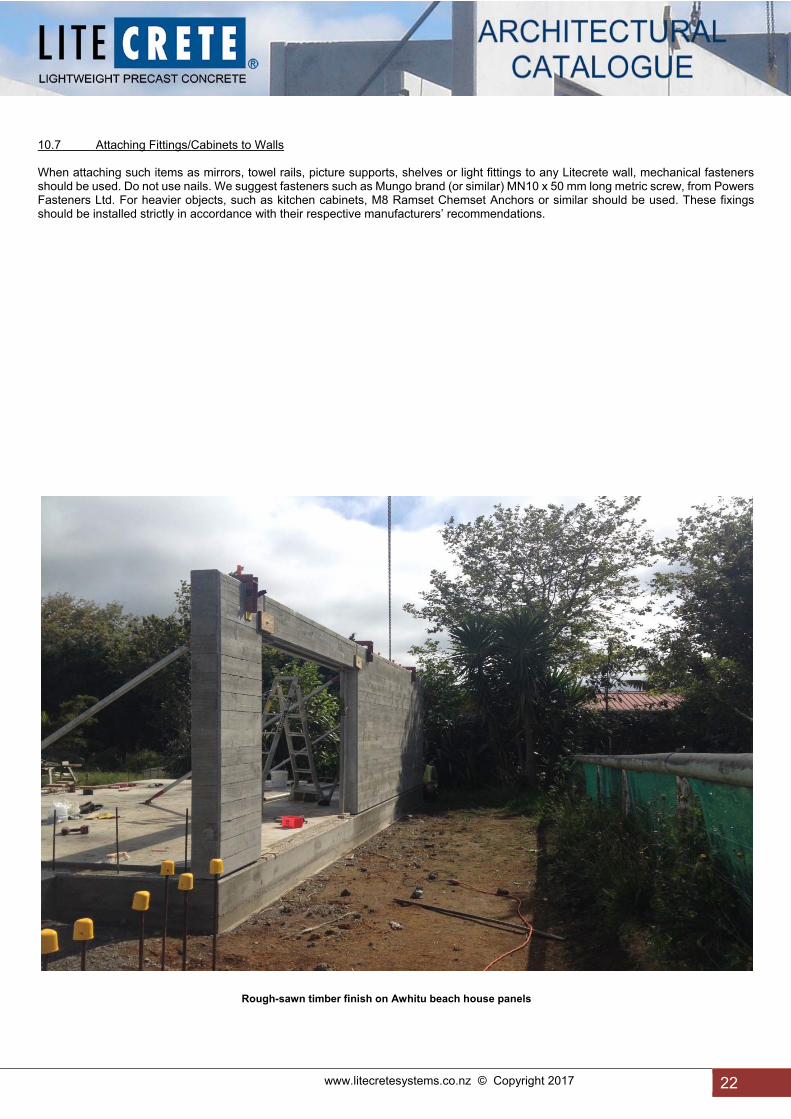
10.7 Attaching Fittings/Cabinets to Walls When attaching such items as mirrors, towel rails, picture supports, shelves or light fittings to any Litecrete wall, mechanical fasteners should be used. Do not use nails. We suggest fasteners such as Mungo brand (or similar) MN10 x 50 mm long metric screw, from Powers Fasteners Ltd. For heavier objects, such as kitchen cabinets, M8 Ramset Chemset Anchors or similar should be used. These fixings should be installed strictly in accordance with their respective manufacturers’ recommendations.
Rough-sawn timber finish on Awhitu beach house panels
23 www.litecretesystems.co.nz © Copyright 2017
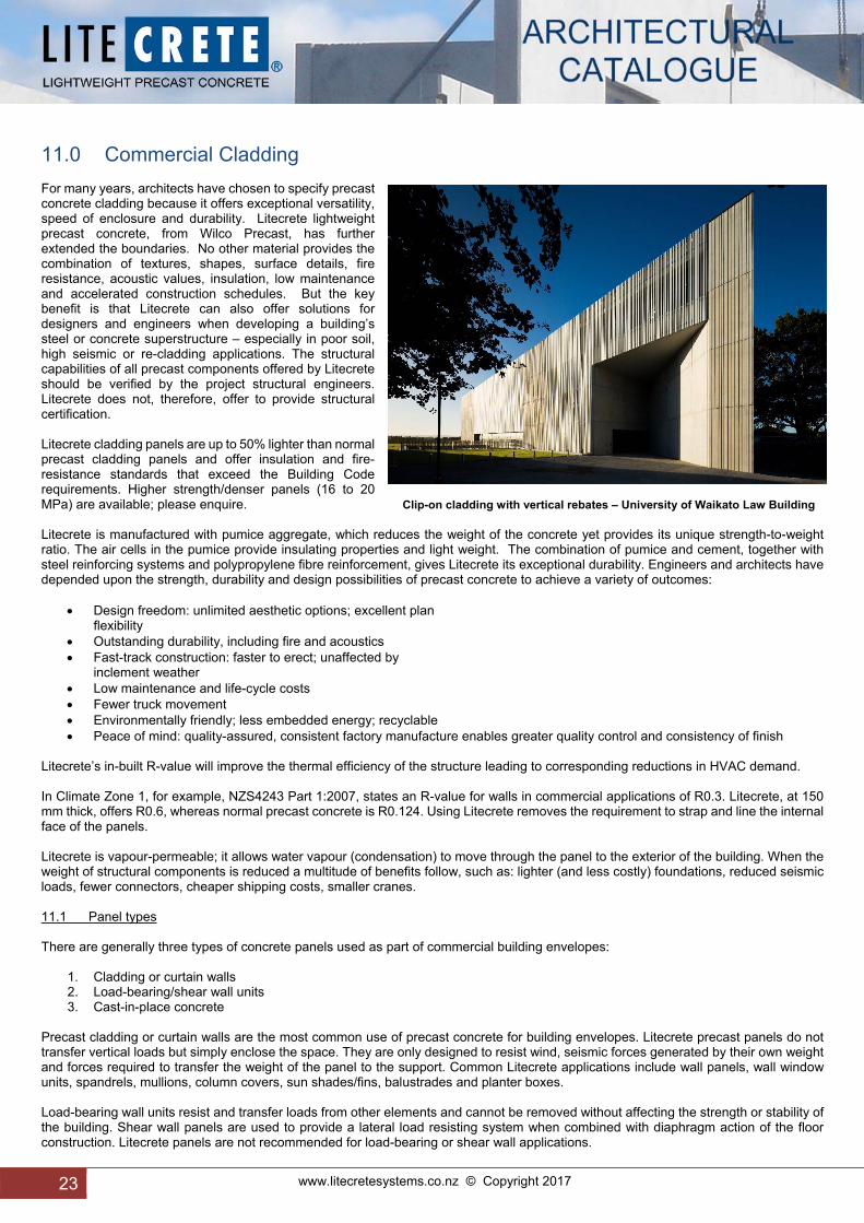
11.0 Commercial Cladding For many years, architects have chosen to specify precast concrete cladding because it offers exceptional versatility, speed of enclosure and durability. Litecrete lightweight precast concrete, from Wilco Precast, has further extended the boundaries. No other material provides the combination of textures, shapes, surface details, fire resistance, acoustic values, insulation, low maintenance and accelerated construction schedules. But the key benefit is that Litecrete can also offer solutions for designers and engineers when developing a building’s steel or concrete superstructure – especially in poor soil, high seismic or re-cladding applications. The structural capabilities of all precast components offered by Litecrete should be verified by the project structural engineers. Litecrete does not, therefore, offer to provide structural certification. Litecrete cladding panels are up to 50% lighter than normal precast cladding panels and offer insulation and fire-resistance standards that exceed the Building Code requirements. Higher strength/denser panels (16 to 20 MPa) are available; please enquire. Clip-on cladding with vertical rebates – University of Waikato Law Building Litecrete is manufactured with pumice aggregate, which reduces the weight of the concrete yet provides its unique strength-to-weight ratio. The air cells in the pumice provide insulating properties and light weight. The combination of pumice and cement, together with steel reinforcing systems and polypropylene fibre reinforcement, gives Litecrete its exceptional durability. Engineers and architects have depended upon the strength, durability and design possibilities of precast concrete to achieve a variety of outcomes:
Design freedom: unlimited aesthetic options; excellent plan flexibility
Outstanding durability, including fire and acoustics Fast-track construction: faster to erect; unaffected by
inclement weather Low maintenance and life-cycle costs Fewer truck movement Environmentally friendly; less embedded energy; recyclable Peace of mind: quality-assured, consistent factory manufacture enables greater quality control and consistency of finish
Litecrete’s in-built R-value will improve the thermal efficiency of the structure leading to corresponding reductions in HVAC demand. In Climate Zone 1, for example, NZS4243 Part 1:2007, states an R-value for walls in commercial applications of R0.3. Litecrete, at 150 mm thick, offers R0.6, whereas normal precast concrete is R0.124. Using Litecrete removes the requirement to strap and line the internal face of the panels. Litecrete is vapour-permeable; it allows water vapour (condensation) to move through the panel to the exterior of the building. When the weight of structural components is reduced a multitude of benefits follow, such as: lighter (and less costly) foundations, reduced seismic loads, fewer connectors, cheaper shipping costs, smaller cranes. 11.1 Panel types There are generally three types of concrete panels used as part of commercial building envelopes:
1. Cladding or curtain walls 2. Load-bearing/shear wall units 3. Cast-in-place concrete
Precast cladding or curtain walls are the most common use of precast concrete for building envelopes. Litecrete precast panels do not transfer vertical loads but simply enclose the space. They are only designed to resist wind, seismic forces generated by their own weight and forces required to transfer the weight of the panel to the support. Common Litecrete applications include wall panels, wall window units, spandrels, mullions, column covers, sun shades/fins, balustrades and planter boxes. Load-bearing wall units resist and transfer loads from other elements and cannot be removed without affecting the strength or stability of the building. Shear wall panels are used to provide a lateral load resisting system when combined with diaphragm action of the floor construction. Litecrete panels are not recommended for load-bearing or shear wall applications.

www.litecretesystems.co.nz © Copyright 2017 24
24
11.2 Support and Anchorage Systems The connections for Litecrete panels are an important component of the facade envelope. Structural design engineers utilise various types of anchors but they are often characterised as gravity and lateral types of connections. The primary purposes of the connections are to transfer load to the supporting structure and provide stability. The criteria used to design precast connections including but not limited to:
Strength Ductility Volume change accommodations Durability Fire resistance Constructability
11.3 Joints and Joint Treatments The numerous joints in a precast concrete envelope are an important aspect of the facade design. The joints between Litecrete units or between Litecrete and other building components must be maintained to prevent leakage through the wall system. Joint design should consider the structural, thermal, and all other factors that affect the performance and movement of a joint. The joint seal should of course be adequately designed to withstand the movement of the joint. All horizontal panel-to-panel joints should be a staggered weather joint (see detail B20 Horizontal panel joint). 11.4 Common Backup Wall Elements In commercial construction, the most common back-up wall element for (typically 150 mm thick) Litecrete wall systems is an insulated, metal stud back-up wall assembly. Alternatively, for apartment buildings, 220 mm thick Litecrete can be used as the total external wall assembly, offering an in-built insulation which complies with the Building Code requirements. A backup airseal, such as a neoprene gasket, can be installed on the vertical and horizontal internal joints (see detail C1 High-rise Construction Joint). Plasterboard can be direct fixed to the internal face, if required or the surface can be skim-coated and painted. This can save costs and construction time. 11.5 Structural Aspects of Design Litecrete wall systems are most often constructed as a curtain wall or veneer, in which no building loads are transferred to the concrete panels. Most typically the wall system must resist lateral loads directly imparted on it, such as from wind and earthquake, as well as vertical loads resulting from the self-weight of the precast wall system itself. These loads must be transmitted through the wall system and secondary structural elements to the building's structure. Other loads such as erection, impact, construction related, and transportation must also be considered in the design. It is important to evaluate the design, detailing and erection of precast panels, in order to avoid imposing unwanted loads onto the panels. The panels are designed in accordance New Zealand Standards. Joints between panels must be wide enough to accommodate thermal expansion and differential movements between panels. Joints between panels are most commonly sealed with proprietary sealant to prevent water penetration in the wall cavity. The wall cavity space and backup wall which is usually covered with a water-resistant membrane provide a secondary line of protection against water penetration into the building. 11.5.1 Deadload Reduction As well as offering an immediate deadload reduction when compared with standard precast, Litecrete can also be used in conjunction with standard precast where the structure’s deadload is critical. Specific Litecrete components such as eyebrows installed above windows, balcony floors, balustrades, parapet panels, spandrels, etc, when considered within the total structural design, can make a surprising contribution to deadload reduction, compared to using standard precast concrete. The parapets, dome support structure and dome base for a Manukau mosque, shown in the adjacent photo, were specified in Litecrete to help reduce the overall deadload on this otherwise standard precast building.
Formliner surface finish – Westpac Tauranga

25 www.litecretesystems.co.nz © Copyright 2017
11.6 Performance Issues 11.6.1 Thermal Performance Despite 150 mm thick Litecrete precast panels having an in-built R-value of R0.6, the thermal mass benefits offered by the Litecrete is negated by, and the wall panels derive their thermal performance characteristics primarily from, the amount of insulation placed in the cavity or within the backup wall. However, 220 mm thick Litecrete cladding panels, with an in-built R0.8 R-value, comply with the insulation requirements of the residential Building Code (H1). Consequently, no backup wall is required. 11.6.2 Moisture Protection The most common moisture protection system used with precast concrete wall systems is a barrier system incorporating a durable joint seal. Where the Litecrete panels are to be left in their natural concrete (raw) state, we recommend the application of a clear matt finish sealer to the external surface after installation. This will allow seasonal precipitation to wash the panels down and help to prevent a build-up of grime on the surface. EG: STO NZ’s “STO PUR” which complies with CCANZ CP 01:2014 – Code of Practice for Weathertight Concrete and Concrete Masonry Construction. Because of the air-entrainer incorporated in the Litecrete mix removes any air pockets which are prevalent in all concrete mixes, the use of proprietary water excluding agents -- such as Xypex -- does not add any benefit. 11.6.3 Fire Protection Pumice concrete is well known for its superior fire resistant properties compared to standard concrete, standard precast and cast-in-place concrete. The inclusion of the polypropylene fibres in the mix assists in fire prevention on the basis that, as the concrete is heated by fire, the fibres melt, creating conduits along which water vapour can dissipate, so avoiding a build-up of pressure and preventing spalling from occurring. In BRANZ test report FR3524 - Fire resistance of a lightweight concrete panel load bearing wall; the 150 mm thick Litecrete wall achieved a 240-minute fire resistance rating. 11.6.4 Acoustics A precast concrete wall system and cast-in-place facade will provide similar performance regarding sound transmission from the exterior to the interior of the building. However, distressed and open joints between panels can provide a condition in which sound transmission to the interior may be increased. Fire/acoustic inter-tenancy walls for apartment and other residential buildings, eg hospitals, hotels, etc. Litecrete 150 mm achieves a 240-minute fire resistance rating (refer BRANZ Fire Resistance Test FR 3524) and offers acoustic systems that achieves up to STC 60. 11.6.5 Material/Finish Durability Litecrete precast panels used in wall systems are available in various finishes and shapes. A Litecrete panel with a highly detailed architectural surface will present challenges in achieving workability of the concrete mix and better consolidation. Litecrete panels with differing depths of surface profiling also require more care in maintaining the required 50 mm concrete cover over the embedded reinforcing steel. In summary, the more complicated the appearance of a precast concrete panel, the more challenging and important the review and approval process and quality control program. Panel cracking, displacements, or other distress conditions can occur at locations where anchors are inadequately or improperly connected. Poor construction is often the result of poor quality control and out of tolerance fabrication or erection of the panels. 11.6.6 Maintenance When properly constructed, Litecrete panels require minimal maintenance. The most important maintenance item is the sealant in joints and protection system (plaster/paint/stain/clear sealant). If a paint, plaster, stain or clear sealing system has been used the coating will require reapplication. The time frame for the various systems varies widely but usually ranges from every 7 to 20 years, depending upon the quality of the product specified. For instance, mineral silicate-based paint systems, which fuse to the minerals in the concrete, are going to prove more durable than acrylics, which sit on the surface. Litecrete precast concrete wall systems allow for a wide variety of colours, finishes and architectural shapes. As Litecrete is made in a controlled factory environment it can be erected in an environment that would not allow for site casting of concrete.

www.litecretesystems.co.nz © Copyright 2017 26
26
Shape, size and finish options – appearance and cost guide Appearance relative Uniformity cost SHAPES Perimeter 4-sides ■ $ Perimeter 5 or more sides ■ $$$$$$ Non-rectangular ■ $$$$$ Curved shapes/surfaces ■ $$$$$ Punched shapes (openings) ■ $$ Returns ■ $$$ SIZES Small panels ■ $$$$ Large panels ■ $ Thicker panels (>180 mm) ■ $$ ACCENTS Plain (no reveals) ■ $ Shallow reveals (<15 mm) ■ $$ Deep reveals ■ $$$ Reliefs (repetitive) ■ $$$ Precast trims and projections ■ $$$ COLOURS Grey cement ■ $ White cement ■ $$$$ Black cement ■ $$$ FINISHES Form finish (F5) ■ $ Coatings (paint) ■ $ Plaster systems ■ $$ Formliner (custom, low repetition) ■ $$$$$ Formliner (high repetition) ■ $$$ Stone/brick veneer (on site by others) ■ $$$$$$ ■ low ■ medium ■ high Concrete is made from natural materials which vary in the colours they yield over time. Samples will represent one colour in the range of colours produced by a mix design. Older samples should only be used as a guide for initial colour and finish selection. Fresh 300 x 300 mm samples should always be used to make final colour and finish selections. As with natural stone, mock-ups produced near to the time of actual production should be used to confirm final colour and finish selections. Oxides used for colouring the concrete are expensive and due to the nature of the minerals contained within pumice aggregate, colour variation is difficult to control. A more cost-effective method of achieving a durable colour to the surface is by the using concrete stains. Such systems offer a broad colour spectrum and offer a 20-year colour-fast warranty. The stain is applied after installation of the panels. Formliners are being used more regularly, however they are only cost-effective where the cost can be amortised over a quantity of panels rather than a one-off. Simple surface rebates can be applied at minimal cost.
Litecrete sills being attached to Litecrete wall panels–Countdown Orewa

27 www.litecretesystems.co.nz © Copyright 2017
12.0 Sustainable Building Sustainable building is the concept of constructing homes and buildings that we need today without depleting resources for future generations. In this new world of “sustainability” information about the strength, durability and indestructible nature of concrete as a resourceful building material is emerging. Amid the tear-down-and-replace mentality still pervasive in the world today, concrete stands out defiantly. Try to replace concrete with an alternative building material and you’ll be hard pressed to find a substitute possessing the same thermal qualities, design flexibility, and permanence. Fortunately, a paradigm shift is taking place in attitudes about resource conservation and sustainability. More builders and homeowners are now embracing sustainable building and concrete is emerging as a champion rather than a rebel. Read on to find out why, and learn how you can use concrete to build environmentally responsible homes without compromising beauty, comfort, or economy. For most homebuilders and homeowners, expressions such as “sustainable development,” “green building,” and “eco-friendly design” weren’t part of the vernacular several years ago (although commercial builders have long been familiar with these terms). But with mounting concerns about rising energy costs and the continued depletion of finite resources, these environmental buzzwords are becoming mainstream. In New Zealand, green building is slowly beginning to show some popularity in residential (and more recently commercial) construction and an increasing number homebuyers are making environmental issues a top priority for new construction and remodeling. Sustainability expands on the basic concept of “reduce, reuse, and recycle.” It seeks to balance sensitivity for the environment with economic and social values. For homeowners, the benefits of green living go beyond environmental stewardship. Sustainable homes also offer many practical, personal, and economic advantages including: • Lower utility costs. Through such strategies as proper site orientation, the use of insulating building materials, and tighter construction to reduce drafts, sustainable homes require much less energy to heat and cool. Sometimes off-grid energy sources, such as solar power, can be used to meet all or part of the home’s electricity needs. • Reduced impact on the surrounding environment and community. Sustainable homes make more use of materials manufactured or harvested in an environmentally responsible manner. They also use materials available locally, not only to reduce transportation impacts (such as fuel consumption and pollution) but also to stimulate the local economy. Attention to landscaping is important as well, with consideration given to minimizing stormwater runoff, which can pollute local waterways. • A healthier, more comfortable living environment. By using non-toxic materials, sustainable homes have better indoor air quality. They also use materials resistant to moisture and rot to eliminate concerns about the growth of hazardous mould and mildew. Exterior walls typically have greater thermal mass, which offers the dual benefits of reducing temperature fluctuations and muffling outdoor noise. • Greater durability with less maintenance. Building with highly durable, low-maintenance materials, such as concrete, extends the useful life cycle of a sustainable home and reduces maintenance and replacement costs. Many homeowners are unaware of the negative impacts their homes and surrounding paved surfaces can have on environmental health. But the effects are dramatic, ranging from resource depletion to climatic changes to disruption of fragile ecosystems. Consider these disturbing facts: With about 25,000 homes built each year, prior to 2008, homes represent 55% to 60% of all environmental impacts of buildings. It can take over 40 trees to build one timber-framed home. Operating a typical home or building over time consumes far more energy than it does to build it, according to Vera Novak, a US environmental specialist and one of the ConcreteNetwork’s industry leaders. While investigating the life cycle of buildings, she found that a mere 2% of total energy is expended for materials and construction and a staggering 98% are used to heat, cool, and power the building. Studies have shown that urban environments have higher temperatures in areas where there are few trees and lots of buildings and paved surfaces. This additional heat (called the “urban heat-island effect”) causes air conditioning systems to work harder, consuming up to 18% more energy. Stormwater runoff is a leading source of the pollutants entering our waterways; about 90% of surface pollutants are carried by the first 150 mm of rainfall. As much as 95% of the hydrocarbons in urban runoff are from the binder and sealer used in asphalt pavements.

www.litecretesystems.co.nz © Copyright 2017 28
28
Litecrete lightweight concrete is a friend of the environment in all stages of its life span, from raw material production to demolition, making it a natural choice for sustainable construction. Here are some of the reasons why: Resource Efficiency. The predominant raw material for the cement in concrete is limestone, the most abundant mineral on earth. Litecrete uses pumice aggregate which is also available in large quantities and is recovered from deposits using very little energy. Durability. Litecrete builds durable, long-lasting structures that will not rust, rot, or burn. Life spans for concrete building products can be double or triple those of other common building materials. Thermal mass. Homes built with concrete foundations and Litecrete concrete walls, and floors are highly energy efficient because they take advantage of concrete’s inherent thermal mass—or ability to absorb and retain heat. This means homeowners can significantly cut their heating and cooling bills and install smaller-capacity HVAC equipment. Reflectivity. Concrete minimises the effects that produce urban heat islands. Light-coloured concrete pavements and roofs absorb less heat and reflect more solar radiation than dark-coloured materials, such as asphalt, reducing air conditioning demands in the summer. Minimal waste. Litecrete can be produced in the quantities needed for each project, reducing waste. After a concrete structure has served its original purpose, the concrete can be crushed and recycled into aggregate for use in new concrete pavements or as backfill or road base. Healthier Environment. VOC emissions from concrete building products are much lower than those for most other building materials. The use of natural lime-cement plaster wall finishes can also significantly reduce total VOC concentrations inside a home. Exposure to toxic mould in homes and buildings has been blamed for ailments ranging from headaches to severe respiratory infections and immune system disorders. Mould can thrive on any organic material, especially in warm, moist, humid conditions. In addition to carpeting, mould can feed on drywall, timber joists and framing and wall sheathing. Litecrete lightweight concrete floors and walls won’t support the growth of toxic mould. Concrete Reabsorbs CO² Emissions During the life of a Litecrete lightweight concrete structure, the concrete carbonates and absorbs the CO² released by calcination during the cement manufacturing process. Once concrete has returned to fine particles, full carbonation occurs, and all the CO² released by calcination is reabsorbed. A recent study indicates that in countries with the most favourable recycling practices, it is realistic to assume that approximately 86% of the concrete is carbonated after 100 years. During this time, the concrete will absorb approximately 57% of the CO² emitted during the original calcination. About 50% of the CO² is absorbed within a short time after concrete is crushed during recycling operations.
Z-shaped Litecrete panels on an almost completed Samoan Consulate in Mangere. The edge details were produced off formliners.

29 www.litecretesystems.co.nz © Copyright 2017
13.0 Construction Details Note that the following details comply with the recommendations set out in “CCANZ CP 01:2014 – CODE OF PRACTICE FOR WEATHERTIGHT CONCRETE AND MASONRY CONSTRUCTION”. For residential construction in Climate Zone 1 the 220 mm thickness detailed achieves an R-value of R0.8, which is as specified in NZBC Clause H1 Energy Efficiency. Both 220 and 150 mm thick panel details, in various formats, are available for downloading on the Litecrete website: www.litecretesystems.co.nz.
D1 Panel Joint Detail – Butt Joint
D2 Panel Joint Detail – Internal/External Corners
D3(2) Panel Joint Detail – Panel/Floor Slab Connection (Option 2)
D3(3) Panel Joint Detail – Panel/Floor Slab Connection (Option 3)
D3(4) Panel Joint Detail – Panel/Masonry Connection
D3(5) Panel/Floor/Concrete Deck Connection
D3(6) Internal Panel/Floor Connection Option 1
D3(7) Internal Panel/Floor Connection Option 2
D4 Panel Detail – Wall/Roof Connection
D5 Window Edge Detail – Sill, Head and Jamb
D6 Window Installation Detail – Single Glazing
D6(1) Window Installation detail – Double Glazing
D7 Panel Detail – Garage Door Lintel
D8 Mid Floor Connection Detail – Timber Joist End/Side Fixing
D8(1) Mid Floor Connection Detail – Metal tray insitu concrete system
D9 Connection Detail – Wall/Timber Frame Connection
D10(1) Panel/Weatherboard Transition
D10(2) Panel/Fibre-cement Board Transition
D11 Parapet Wall Details
D12 Flush Fascia Details
D13 Details – Wall/Roof Junction (Apron Flashing)
D14 Details – Gutter/Wall Junction
D15 Meter Box Details – Head, Sill and Jamb
D16 Pipe Penetration Details
D17 Suspended First Floor Wall Panel Installation
D18 Vertical Control Joint for Paint/Plaster Systems
D19 Narrow Panel Parameters
D20 Horizontal Panel Joint
D21 Cast-In Weld Plates - Flush and Recessed
D22 Ventilation Grille Opening
D23 Cast-in Timber Fillet for Weatherboard Attachment
IW1 Intertenancy Wall - To achieve STC 47
IW2 Intertenancy Wall - To achieve STC 55
IW3 Intertenancy Wall - To achieve STC 60
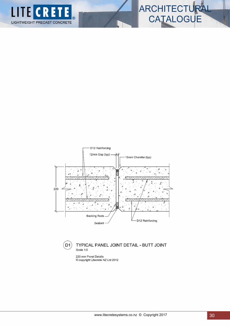
www.litecretesystems.co.nz © Copyright 2017 30
30

31 www.litecretesystems.co.nz © Copyright 2017

www.litecretesystems.co.nz © Copyright 2017 32
32
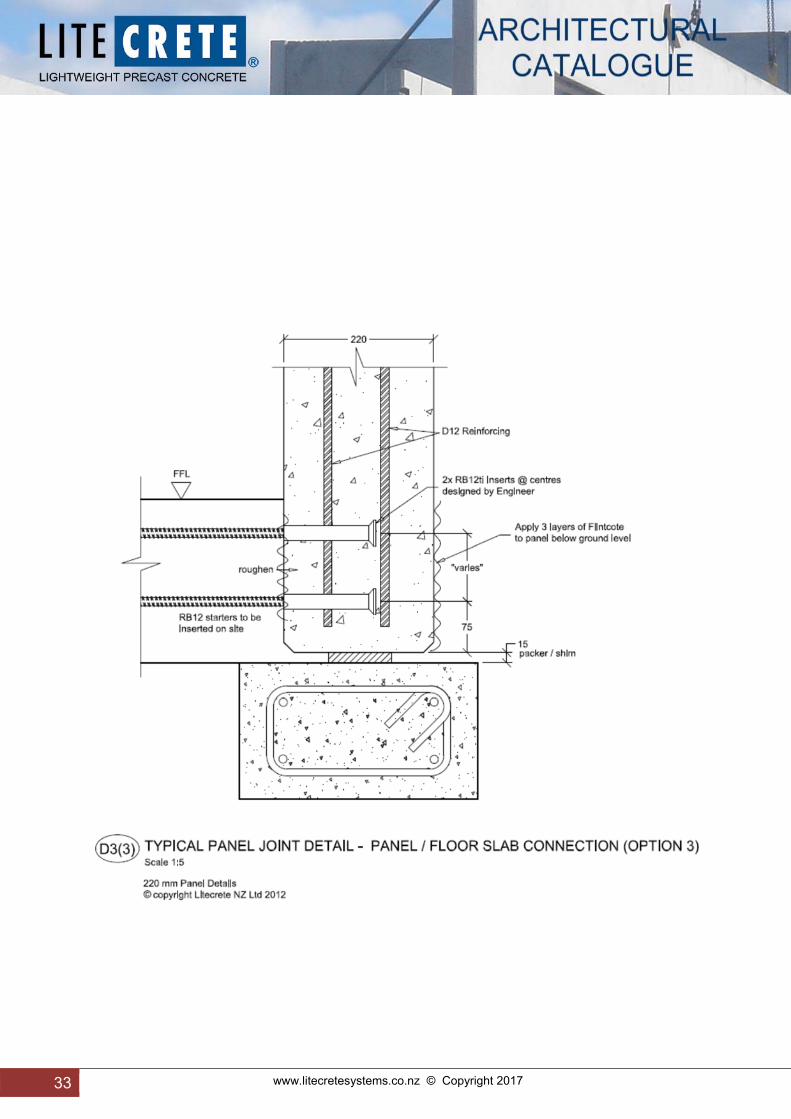
33 www.litecretesystems.co.nz © Copyright 2017

www.litecretesystems.co.nz © Copyright 2017 34
34

35 www.litecretesystems.co.nz © Copyright 2017

www.litecretesystems.co.nz © Copyright 2017 36
36

37 www.litecretesystems.co.nz © Copyright 2017

www.litecretesystems.co.nz © Copyright 2017 38
38

39 www.litecretesystems.co.nz © Copyright 2017

www.litecretesystems.co.nz © Copyright 2017 40
40

41 www.litecretesystems.co.nz © Copyright 2017
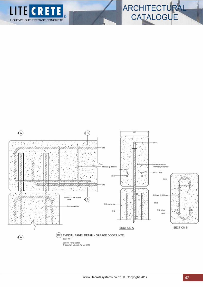
www.litecretesystems.co.nz © Copyright 2017 42
42

43 www.litecretesystems.co.nz © Copyright 2017

www.litecretesystems.co.nz © Copyright 2017 44
44

45 www.litecretesystems.co.nz © Copyright 2017

www.litecretesystems.co.nz © Copyright 2017 46
46

47 www.litecretesystems.co.nz © Copyright 2017

www.litecretesystems.co.nz © Copyright 2017 48
48
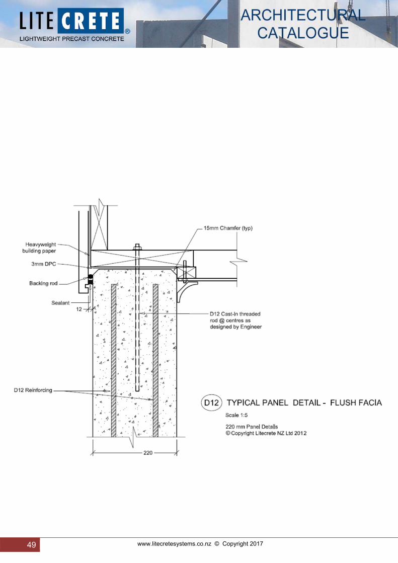
49 www.litecretesystems.co.nz © Copyright 2017

www.litecretesystems.co.nz © Copyright 2017 50
50

51 www.litecretesystems.co.nz © Copyright 2017

www.litecretesystems.co.nz © Copyright 2017 52
52

53 www.litecretesystems.co.nz © Copyright 2017

www.litecretesystems.co.nz © Copyright 2017 54
54

55 www.litecretesystems.co.nz © Copyright 2017
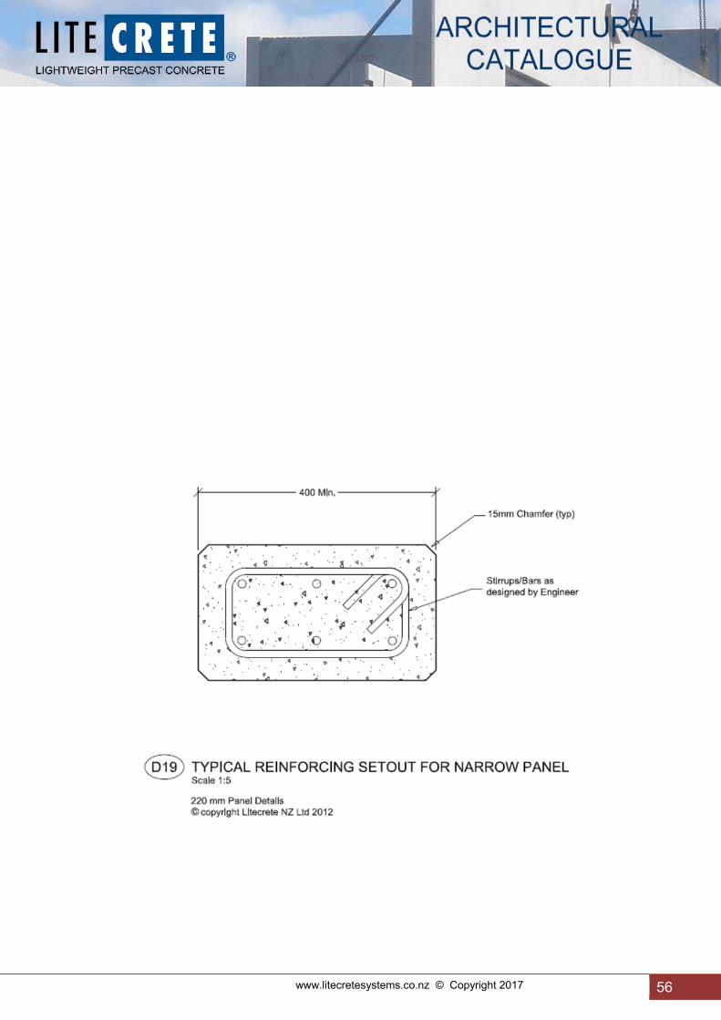
www.litecretesystems.co.nz © Copyright 2017 56
56

57 www.litecretesystems.co.nz © Copyright 2017

www.litecretesystems.co.nz © Copyright 2017 58
58

59 www.litecretesystems.co.nz © Copyright 2017

www.litecretesystems.co.nz © Copyright 2017 60
60

61 www.litecretesystems.co.nz © Copyright 2017

www.litecretesystems.co.nz © Copyright 2017 62
62

63 www.litecretesystems.co.nz © Copyright 2017
www.litecretesystems.co.nz © Copyright 2017 64
14.0 Appendix
Typical Specification
(Contact Litecrete for adaptable Word version) LITECRETE LIGHTWEIGHT PRECAST CONCRETE: MANUFACTURE & SUPPLY 1.1 PRELIMINARY
Refer to the Preliminaries and General Clauses, which are equally binding on all trades. 1.2 SCOPE
This section of the contract consists of: 1.2.1 The provision of Litecrete lightweight concrete panels. 1.2.2 Supply of full shop drawings for approval, detailing the installation.
2.0 GENERAL 2.1 WORKMANSHIP:
All work shall be carried out by skilled tradesmen using adequate and proper equipment and methods, in accordance with best trade practice, to the manufacturer’s instructions and recommendations and shall be of the best description, to the satisfaction of the Architect and product manufacturer.
2.2 MANUFACTURER’S DOCUMENTS
Copies of the above literature are available by phoning: Litecrete (NZ) Ltd, telephone (09) 295 1051.
Requirements 2.3 SHOP DRAWINGS
Provide details showing but not limited to: - size and spacing of reinforcement - position and layout of lifting anchors - details of panel edges - layout of form tie holes where exposed to view - form surfaces for each finish specified.
2.4 PRODUCER STATEMENT – DESIGN – PS1
Provide a producer statement from a suitably qualified person for: - panel reinforcement for construction - lifting anchor layout - installation
2.5 PRODUCER STATEMENT – CONSTRUCTION – PS3
Provide a producer statement from a suitably qualified person for: - supply of precast items NOTE: PS2 and PS4 by others
2.6 PANEL SURFACE
Confirm the required surface finish for both sides of the panel. Refer to 5.0 SCHEDULES for surface finishes.
2.7 SAMPLE PANELS Provide 1 metre x 1 metre panels of the following specified finishes ………………………………………………………………... Samples to be the same thickness and made using the same manufacturing parameters as for the lightweight precast panels. Refer to 5.4 SCHEDULES for sample panel requirements.

65 www.litecretesystems.co.nz © Copyright 2017
2.8 QUALIFICATION, OFF SITE WORK
Use only precast concrete workers skilled and experienced in form making, casting, transportation and erection of precast items.
Performance
2.9 PROVIDE CERTIFICATES
Provide certificates and any other evidence that the finish will comply with the standard of performance specified. 3.0 PRODUCTS
3.1 Materials 2.1.1 Exterior/interior wall panels: All lightweight concrete wall panels shall be Litecrete panels as manufactured by Litecrete (NZ) Ltd, Papakura, to approved shop drawings, and shall comprise 220/180 mm (or specified thickness) solid lightweight concrete with steel reinforcing; one face smooth ex-mould finish, the other trowelled smooth. Litecrete cladding panels stored on site should be stored vertically, on a level surface off the ground, and covered for protection from other trades. 2.1.2 Lintels: All lightweight concrete lintels shall be Litecrete as manufactured by Litecrete (NZ) Ltd, Papakura, to approved shop drawings, purpose designed to suit the specific loading requirements. Joint connections as specified by the engineer.
3.2 Components 3.2.1 LIFTING ANCHORS 3.2.2 TEMPORARY PROPPING INSERTS
Use Reid TIM 16 x 75 cast-in inserts on internal face as fixing points for temporary propping of panels. 3.2.3 CAST IN STEEL ITEMS
Manufacture to detail and to the requirements of 3411 STRUCTURAL STEELWORK. Where required, hot dip galvanise after manufacture to a coating weight of 600 gm/m².
3.2.4 BOND BREAKER
Specifically designed proprietary mould release agent.
4.0 EXECUTION
Conditions 4.1 HANDLE, TRANSPORT AND STACK
Handle, transport and stack panels to ensure support that avoids distortion and stress and at the same time protects the finished surfaces from chipping, scoring, cracking or other disfigurement.
4.2 TOLERANCES, PRECAST PANELS
Construct panels to the tolerances as per NZS 3109:1992, Table 5.1 Locate panels to the following tolerances: Deviation of the panel from the specified final position in the structure: 15 mm.
Application 4.3 APPLY BOND BREAKER
As per manufacturer’s recommendations. 4.4 SECURE REINFORCEMENT
Secure adequately with tying wire and place accurately where detailed, supported and secured against displacement. 4.5 CONCRETE PLACING

www.litecretesystems.co.nz © Copyright 2017 66
Carefully place concrete in layers so that all parts of the mould are completely filled and full contact is made with the face to give a totally uniform finish. Use approved compaction techniques with power driven vibrators to give a uniform, void-free concrete panel.
4.6 CASTING IN ITEMS
Accurately cast in all embedded items and fixings as detailed with full compaction all round. Where bolts are to be cast in also provide the nut (free moving on the bolt).
4.7 CURING
Confirm in writing the system to be used for curing concrete. 5.0 SCHEDULES 5.1 SURFACE FINISHES – As per NZS 3114:1987
Formed surfaces: F5 Unformed surfaces: U3
5.2 BOND BREAKER
Manufacturer: FBS Ltd Brand name: Discrete
5.3 SURFACE FINISHES
Location Finish ………………………… ………………………..
5.4 SAMPLE PANELS
Finish: ………………… LITECRETE LIGHTWEIGHT PRECAST CONCRETE: INSTALLATION 1.0 GENERAL
Related work 1.1 RELATED SECTIONS
For supply refer to LITECRETE LIGHTWEIGHT PRECAST CONCRETE, MANUFACTURE & SUPPLY.
Documents 1.2 DOCUMENTS REFERRED TO
Documents referred to in this section are listed in 1.3 MANUFACTURER’S DOCUMENTS
Copies of the above literature are available by phoning:
Litecrete (NZ) Ltd, telephone (09) 2951051
Requirements 1.4 SITE LOADINGS, PERMANENT STRUCTURE
In order to prevent damage to supporting structure, provide details of imposed loads to permanent structure from casting, stacking of precast items and how these loads will be dispersed so as not to damage the structure.
2.0 PRODUCTS
Components

67 www.litecretesystems.co.nz © Copyright 2017
2.1 SEATINGS
Rigid plastic shims/levelling pads. Accessories
2.2 SEALANTS - JOINT
Polysulphide, polyurethane or silicone gap-filling proprietary sealants. 3.0 EXECUTION
Conditions 3.1 TOLERANCES, ONSITE EXECUTION
Locate precast items to the following tolerances: Plan: ±10 mm Vertical: ±1 mm per metre
Finishing
3.2 FIT GASKETS
Fit gaskets to panel joints in sequence to fully occupy the joint and achieve the flexibility required by the manufacturer. 3.3 SEALANTS - JOINT
Ensure at time of erection, that the limits of acceptable joint variation (from the manufacturer's requirements) for each product are maintained. Prepare joints, protect adjoining surfaces, seal joint surfaces, fit limiting rods and insert sealant to the manufacturer's requirements and temperature limits. Completion
3.4 CLEAN AND DRESS
Clean and dress panels externally and internally to leave them to the standard of finish specified and without blemish, ensuring following work can be completed to the required standard.
3.5 CLEAN UP
Clean up surrounding areas of trade waste and remove temporary works required for the installation of the precast concrete items.
3.6 REMOVE
Remove debris, unused materials and elements from the site. 4.0 SCHEDULES 4.1 GASKETS
Manufacturer: …………….. Type/number: ……………..
4.2 SEATINGS (leveling shims)
Manufacturer: Reids Brand name: Swift Shim
4.3 FLASHINGS 4.4 SEALANTS - JOINT
Manufacturer: Sika joint sealant Type/brand: “Construction AP” or “AT Facade”

www.litecretesystems.co.nz © Copyright 2017 68
14.1 Material Safety Data Sheet Product Name: Litecrete Lightweight Precast Concrete STATEMENT OF HAZARDOUS NATURE: This product is classified as not hazardous according to the criteria of OSH. However, dust generated from the cutting, drilling or grinding of all concrete products, including this product, is hazardous. MANUFACTURER: Litecrete (NZ) Ltd 66 Boundary Road Papakura Auckland New Zealand Telephone: (09) 295 1051 Facsimile: (09) 296 5563 IMPORTANT NOTICE: This Material Safety Data Sheet (MSDS) is issued by Litecrete (NZ) Ltd, in accordance with OSH (Occupational Safety and Health) guidelines. As such, the information in it must not be altered, deleted or added to. Litecrete (NZ) Ltd will issue a new MSDS when there is a change in product specifications and/or OSH guidelines/regulations. Litecrete (NZ) Ltd will not accept any responsibility for any changes made to its MSDS by any other person or organisation. Description: Product name: Litecrete Applicable In: New Zealand Manufacturer's Product Code: Not Applicable UN number: None Allocated Dangerous goods class & Subsidiary Risk: None Allocated Hazchem code: None Allocated Poisons schedule number: None Scheduled Use: Litecrete lightweight concrete has a wide variety of applications, such
as wall and roofing panels in residential commercial and industrial construction projects.
Physical Description/Properties: Appearance: Solid concrete – light grey colour Boiling Point: (ºC) Not Determined Melting Point: (ºC) Not Determined Vapour pressure: Not Determined Specific gravity (H²O = 1) 1.35 Flashpoint: Not Applicable Flammability Limits: Not Flammable Solubility in water: Not Soluble pH, at stated concentration >7.0 Ingredients: Chemical Name: CAS Number: Proportion: Exposure Limits: Portland cement 65997-15-1 +/-30% 10 mg/m³ insp dust Pumice, coarse and fine 1332-09-8 +/-50% 0.2 mg/m³ resp polypropylene fibre (polyolefin) 9003-07-0 +/-1% 5 mg/m³ resp Water +/-18% Steel rod and bar and/or steel mesh <10% Admixtures (such as water +/-1% reducers, plasticisers and waterproofing agents)
69 www.litecretesystems.co.nz © Copyright 2017
Health Hazard Information Note: Concrete products in their intact state and as delivered do not release airborne dusts, but crystalline silica (quartz) dust may be produced during cutting, drilling, grinding, chasing and other machining of the product. Concrete dust contains crystalline silica, and repeated inhalation of crystalline silica may cause serious illness (see below - Health effects, chronic). Repeated inhalation of crystalline silica may add or multiply the serious health effects caused by tobacco smoking. Concrete dusts, in association with sweat and friction can lead to skin irritation and dermatitis, and the dust may be irritating to the eyes and upper respiratory system. Health Effects of Concrete Dust Acute: Swallowed: Unlikely under normal conditions of use, but swallowing concrete dust may cause irritation of the mouth and throat and may result in abdominal discomfort. Eye: Concrete dust is irritating and corrosive to the eyes causing watering and redness and may result in corneal inflammation and ulceration. Skin: The dust, particularly in association with heat and sweat, may irritate the skin, resulting in itching and occasionally a red rash. Inhaled: Concrete dust is irritating to the nose, throat and lungs, especially in people with upper respiratory tract or chest complaints such as asthma. Chronic: Inhaled: Repeated exposure to the dust may result in increased nasal and respiratory secretions and coughing. Repeated inhalation of dry concrete dust containing crystalline silica can cause scarring of the lung (silicosis), lung cancer, and chronic bronchitis, and may increase the risk of scleroderma (thickening of the connective tissue) and kidney disease. Skin: Repeated skin contact with the dust can lead to skin irritation and dermatitis. Concrete dust may cause sensitisation in some people resulting in dermatitis. First Aid Swallowed: Give plenty of water to drink to flush mouth and throat and do not induce vomiting. Eye: Flush thoroughly with flowing water for at least 15 minutes as concrete is alkaline. If symptoms/irritation or redness persists, seek medical attention. Skin: Flush dust off skin with running water. Wash with soap and water. Seek medical attention if there is any rash or redness of the skin. Inhaled: Remove to fresh air. Seek medical attention if any respiratory symptoms. First Aid Facilities: Eyewash station and washing facilities. Advice to Doctor: Treat symptomatically. Precautions for Use Exposure Standards: (Applicable to situations where concrete dust is created by operations).There is no specific OSH standard
for concrete dust. Exposure of persons to concrete dust should be kept as low as practicable and the occupational exposure standard for respirable crystalline silica must be observed. Respirable crystalline silica: 0.2 mg/m³ time-weighted average (TWA).
Engineering Controls: Keep levels of respirable crystalline silica (quartz) in work areas as low as practicable. When cutting or
drilling, external openings such as doors and windows generally provide adequate ventilation. Local mechanical ventilation may be required in areas where dust could escape into the work environment.
Ventilation: Ventilation, either through natural means or by mechanically assisted ventilation must be maintained
throughout work areas to reduce dust levels to as low as practicable and to within the occupational exposure standards.
Special Considerations: Avoid contact with skin and dry concrete dust. Wear personal Repair / Maintenance: protective equipment and clothing as listed below. Wash down machinery and equipment prior to repairs
and maintenance. If hosing down plant, wear a face shield. Personal Protection: Skin Protection: Wear loose, comfortable clothing and light duty gloves (AS2161: Occupational Protective Gloves -
Selection, Use and Maintenance). Wear safety shoes and gloves. Wash work clothes regularly. Eye Protection: Dust resistant safety spectacles with side shields (AS/NZS1336: Recommended Practices for Eye
Protection in the Industrial Environment) should be worn when cutting or drilling concrete and dusts are likely to be generated.

www.litecretesystems.co.nz © Copyright 2017 70
Respiratory Protection: If dusts are generated wear appropriate respiratory protection approved for particulates: ie dust. For
example a class P1 or P2 replaceable filter or disposable half face-piece particulates respirator should be worn when using power tools for wet or dry cutting, drilling, chasing, routing or other machining, or when dust is generated by other processes. Respirators should comply with AS/NZS 1716 and be selected, used and maintained in accordance with AS/NZS 1715.
Personal Hygiene: Do not smoke whilst drilling or cutting concrete products. Flammability: Not flammable, does not support combustion of other materials. Safe Handling Information Storage and Transport: Mass of individual lightweight concrete products can range from 50 kg up to 10 tonnes. Litecrete (NZ) Ltd
can provide additional information on the handling and transportation of specific items. Some Litecrete products are manufactured with projecting steel reinforcing rods or fastenings. Additional care is required during handling of such products to prevent injury.
Spills and disposal: Dispose of offcuts or waste in an authorised landfill site in accordance with local authority guidelines. Fire/explosion hazard: Material is non-flammable. (Refer BRANZ Fire Resistance Test FR3524). Does not cause dust
explosions. Smoking and Other Dust: Inhalation of airborne particles from other sources, including those from cigarette smoke, may increase
the risk of lung disease. It is recommended that all storage and work areas should be non-smoking zones, and other airborne contaminants be kept to a minimum.
Contact Point For further information on this product, please contact: Litecrete (NZ) Ltd 66 Boundary Road Papakura Auckland New Zealand Telephone: (09) 295 1051 Facsimile: (09) 296 5563 Email: [email protected] Website: www.litecretesystems.co.nz
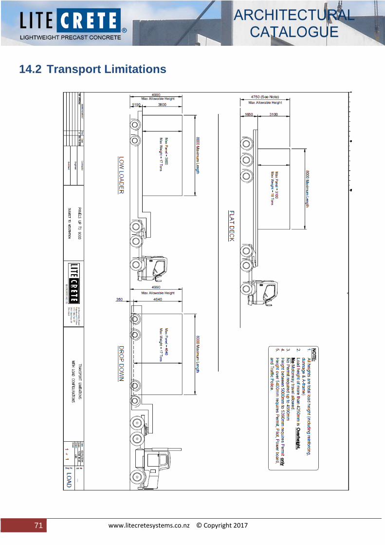
71 www.litecretesystems.co.nz © Copyright 2017
14.2 Transport Limitations