design challenges in the development of fast pick-and...
TRANSCRIPT

IntroductionNew Design Challenges
Alternative ArchitecturesTeaching & Research Topics
Conclusions
Design Challenges in the Development of FastPick-and-Place Robots
NSF Workshop on 21st Century Kinematics
Jorge Angeles
Centre for Intelligent Machines &Department of Mechanical Engineering
McGill UniversityMontreal, Quebec, Canada
Angeles, J. Research Projects 1

IntroductionNew Design Challenges
Alternative ArchitecturesTeaching & Research Topics
Conclusions
Outline
1 Introduction
2 New Design Challenges
3 Alternative Architectures
4 Teaching & Research Topics
5 Conclusions
Angeles, J. Research Projects 2
IntroductionNew Design Challenges
Alternative ArchitecturesTeaching & Research Topics
Conclusions
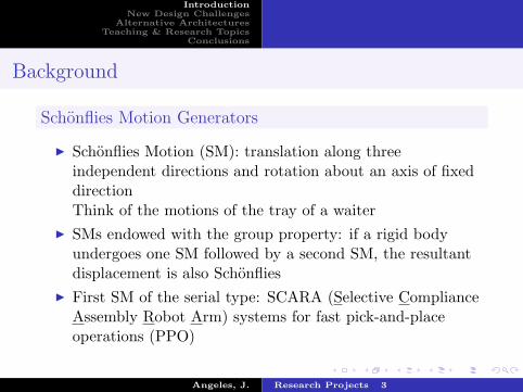
Background
Schonflies Motion Generators
I Schonflies Motion (SM): translation along threeindependent directions and rotation about an axis of fixeddirectionThink of the motions of the tray of a waiter
I SMs endowed with the group property: if a rigid bodyundergoes one SM followed by a second SM, the resultantdisplacement is also Schonflies
I First SM of the serial type: SCARA (Selective ComplianceAssembly Robot Arm) systems for fast pick-and-placeoperations (PPO)
Angeles, J. Research Projects 3

IntroductionNew Design Challenges
Alternative ArchitecturesTeaching & Research Topics
Conclusions
Background (Cont’d)
I Fastest SCARA system: Adept Technology COBRA s600(ca. 1999): capable of 2 cycles/s over an industry-adoptedtest cycle
The industry-adopted test cycle for SCARA systems
I Turning requirement: while on the horizontal segment,moving plate (MP) must turn 180◦ ccw one way, cw whenreturning
Angeles, J. Research Projects 4

IntroductionNew Design Challenges
Alternative ArchitecturesTeaching & Research Topics
Conclusions
Current Solutions
Serial ArchitecturesI RRRP architecture: Adept’s COBRA s600, capable of 2
cycles/s (ca. 1999)I RΠΠR: ABB IRB460, 110 kg capacity, 0.6 cycles/s, 2012
RRRP architecture
RΠΠR architecture
Angeles, J. Research Projects 5
IntroductionNew Design Challenges
Alternative ArchitecturesTeaching & Research Topics
Conclusions
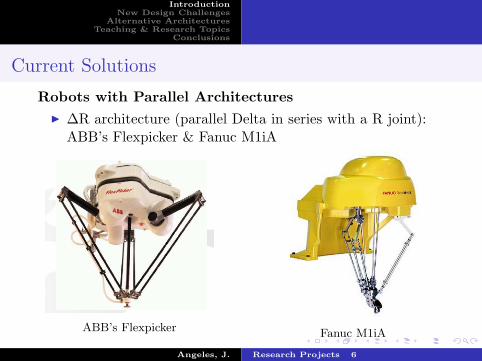
Current Solutions
Robots with Parallel ArchitecturesI ∆R architecture (parallel Delta in series with a R joint):
ABB’s Flexpicker & Fanuc M1iA
ABB’s Flexpicker Fanuc M1iA
Angeles, J. Research Projects 6

IntroductionNew Design Challenges
Alternative ArchitecturesTeaching & Research Topics
Conclusions
Current Solutions (Cont’d)
Robots with Parallel ArchitecturesI Fully parallel architecture: Adept’s Quattro, ∼ 3 cycles/s
Adept’s Quattro
Angeles, J. Research Projects 7

IntroductionNew Design Challenges
Alternative ArchitecturesTeaching & Research Topics
Conclusions
Current Solutions
Pros of Parallel ArchitecturesI Higher throughput: Quattro’s speed is three cycles/sI Lighter structure than serial robots
Cons of Parallel ArchitecturesI Larger footprint than that of serial robotsI Presence of four limbs a challenge to meet the turning
requirement
Angeles, J. Research Projects 8

IntroductionNew Design Challenges
Alternative ArchitecturesTeaching & Research Topics
Conclusions
Challenges
I Reduce footprint of parallel robotsI Meet turning requirement with a simple mechanismI Simpler mechanisms ⇒ reduce complexity. How to measure
or define complexity?
Angeles, J. Research Projects 9

IntroductionNew Design Challenges
Alternative ArchitecturesTeaching & Research Topics
Conclusions
Alternative Architectures—Two-limb SMG Robots
Underlying theme:
Innovate by means of minimally-complex designs thatsatisfy all the functional requirements and designspecifications
I Two-limb SMG robots
McGill SMG An isoconstrained SMGI New design challenges brought about
Angeles, J. Research Projects 10

IntroductionNew Design Challenges
Alternative ArchitecturesTeaching & Research Topics
Conclusions
Design Challenge 1: The DrivesMotors
Drive Units
Proximal modules
Distal modules
Moving platform
Figure 2: The McGill Schonflies-Motion Generator
16A planetary gear train A spherical “homokinetic” mechanism
A RHHR linkage designed to drive a C joint
Angeles, J. Research Projects 11

IntroductionNew Design Challenges
Alternative ArchitecturesTeaching & Research Topics
Conclusions
Design Challenge 1: The Drives (Cont’d)
Alternative Pan-tilt Mechanisms
Panning Π linkage Five-bar tilting linkage
Angeles, J. Research Projects 12
IntroductionNew Design Challenges
Alternative ArchitecturesTeaching & Research Topics
Conclusions
Design Challenge 2: A Stiff Structure
I link materials: carbon fiberI the McGill SMG entails a symmetric structure of the
RΠΠRRΠΠR type, with a home posture in which the fourΠ joints lie in the same plane. This renders the structurehighly flexible in a direction normal to that plane
I the structure of two-limb isoconstrained SMG appearsmuch stiffer, by virtue of the relative layout of the axes ofits two C joints
Angeles, J. Research Projects 13

IntroductionNew Design Challenges
Alternative ArchitecturesTeaching & Research Topics
Conclusions
Design Challenge 3: The Gripper-turning Mechanism
I H4 SMG — highly complex, with a multitude of gearsI two-limb isoconstrained SMG — extremely simple, suitable
for the turning operationI an alternative double-screw mechanism, proposed for
McGill SMG — two parallel screws of identical leads,opposite hands, parellel axes
OI4
OII4
h1
h2
aII5
φ
P
Angeles, J. Research Projects 14

IntroductionNew Design Challenges
Alternative ArchitecturesTeaching & Research Topics
Conclusions
Teaching & Research Topics
I Link between engineering design and kinematic synthesis- Include Hartenberg & Denavit’s type synthesis and number
synthesis within the conceptual-design phase: qualitativesynthesis
I Exact synthesis not a realistic approach to practicalreal-life problems: approximate synthesis
- Computational-kinematics methods should be linked withoptimization methods
- Optimization methods target error minimization in theapproximate synthesis
- error-compensation by means of model-based kinematiccontrol
- Fundamental research needed in the formulation ofoptimization problems in the realm of dual algebra
Angeles, J. Research Projects 15

IntroductionNew Design Challenges
Alternative ArchitecturesTeaching & Research Topics
Conclusions
Examples of Kinematic Synthesis Projects
I Assigned within MECH 541 Kinematic Synthesis at McGillUniversity
I The term comprises 13 weeks, at 3h/week of lecturesI Three mini-projects assigned during the winter 2013 termI Each mini-project mark counts for 25% of course mark, the
balance 25% is assigned to a Class test (no final exam)
Angeles, J. Research Projects 16

MECH 541 Kinematic SynthesisMini-project 1: The Design of the Actuation Mechanism of a
Cylindrical JointStatement of Work
Assigned: Tuesday January 10th, 2012 Due: Wednesday February 9th, 2012
Shown in Fig. 1 are four instances of Schonflies-motion generators that are billed as isocon-strained. The latter means that each instance is isostatic. Each is composed of a moving plate(MP) or gripper, that is capable of Schonflies displacements of vertical axis. As well, each instanceis composed of two limbs that connect the gripper with the base, onto which two horizontal shaftsare rigidly attached. Moreover, in all four instances, the pitches of the two screws rigidly attachedto the gripper are distinct.
(a) (b) (c) (d)
Figure 1: A novel pick-and-place robot in four instances: a) CUHHUC; b) CRRHHRRC; c)CRPHHPRC; and CPRHHRPC
1. Show that each instance is indeed a Schonflies-motion generator.
2. Show that each instance is isostatic. In other words, show that, if the statics equations arewritten for each individual rigid link, then the number of components of unknown reactionforces and moments equals the number of statics equations. this property is quite important,as it allows for assemblability, which an overconstrained chain does not.
3. Each instance is driven by two actuated cylindrical joints, which are not readily availableoff-the-shelf. Propose as many variants as possible of an actuated cylindrical joint, with itstwo motors mounted on the same base.
4. Of the variants that you propose, pick up one that you consider to be the best, givingreasons to support your choice. Then, produce an embodiment of this specific variant usingcommercial CAD software. Choose DC brushless servomotors capable of 3 turns/s, rated at500 watt.
1


MECH 541 Kinematic SynthesisMini-project 2: The Design of a Quasi-homokinetic Linkage for
Shafts with Skew AxesStatement of Work
Assigned: Thursday February 9th, 2012 Due: Thursday March 8th, 2012
Ultimate Robotics Inc. (URI) is designing a parallel robot intended for Schonflies motiongeneration, with two limbs, each limb is driven by two actuators, to drive a panning Π joint,as depicted in Fig. 1. The pan axis A should pass through the mid point of link 1. Arequirement of parallel robots is that all its actuators be mounted on the fixed base, 0 in thefigure. The pan axis can be driven by directly coupling the pan shaft to the shaft of one ofthe two actuators. The tilt axis, one of the two joints of link 1, is to be driven with a secondactuator coaxial with A.
Given that direct-drive motors will be used as actuators, gears are ruled out in the drivingsystem. Instead, a RCCC linkage is to be designed to drive the tilt axis from axis A. You havebeen hired to design the linkage, which will function as a quasi-homokinetic transmission,that is, a linkage capable of approximately producing a 1:1 velocity ratio between actuatorrate and tilt rate, for a 120◦ sweep of the tilt angle.
Figure 1: A panning Π joint
The R&D Department of the company reports that their records show that a location ofthe dial zeros of the input and output dials be set at values of 86◦ and −26◦, respectively.
1

For the translation d1 of the output joint, you are free to prescribe its motion program{ (d1)i, ψi }m1 , but it is advisable that this program be symmetric with respect to d1 = 0.
The client specifies that the distance between the two shafts is 400 mm, while d2 in theDenavit-Hartenberg notation is to be given the same numerical value. An expert designengineer of URI claims that, given the homokinetic motion desired, the input an output axesshould play the same role, and hence, α4 = α2 and, for symmetry, a4 = a2. Your job is thus
1. To find the optimum values of the remaining Denavit-Hartenberg parameters that bestfit the prescribed homokinetic transmission in the least-square sense.
2. To produce error plots of the generated output angle-and-displacement values w.r.t.their prescribed counterparts, along with rms values of these errors, and
3. To produce a CAD rendering of the linkage thus designed. URI will give you a bonusif you produce an animation of the designed linkage.
2

MECH 541 Kinematic SynthesisMini-project 3: The Design of a Landing Gear for Small Aircraft
Statement of Work
Assigned: Monday March 19th, 2012 Due: Friday April 13th, 2012 at 5:00 p.m.
AeroDesign Inc. is developing a compact landing gear for small aircraft, consisting of a planar
four-bar linkage. The linkage is to be anchored to the fuselage, indicated as the shaded region.
Produce a design that will do the job, with the fixed R joints as close as possible to the fuselage
boundary, and outside of the working region, i.e., the region swept by the wheel when it is being
either retracted or deployed, as shown in Fig. 1. The client hasn’t as yet decided what tyre model
to use. For this reason, the client needs your design in terms of the tyre radius r. To this end, the
client has specified the relations below:
a = 2r, b = 3r
a
b
Γ
r
Figure 1: A landing gear for small aircraft
Moreover, the tyre can be assumed to fit in a rectangle of width r/3 and height r.In order to make the operations of deployment and retraction as smooth as possible, the client
wants a smooth trajectory Γ to be followed by the midpoint of the tyre, defined as the intersection
of the tyre axis with the tyre midplane. An AeroDesign Inc. senior engineer has advised you to
define Γ as a fourth-degree Lame curve, namely,
(
x
a
)
4
+
(
y
b
)
4
= 1
1