design considerations for a multiple-reactor demon · pdf filecompact multiple-reactor design...
TRANSCRIPT
Design Considerations for a Multiple-Reactor DEMON Process Treating Sludge Liquors
from a Thermal Hydrolysis Anaerobic Digester
Andrew Shaw, Black & Veatch
Peter Thomson, Black & Veatch
Beverley Stinson, AECOM
Salil Kharkar, DC Water
Sudhir Murthy, DC Water
Chris deBarbadillo, DC Water
Nick Passarelli, DC Water
Bernhard Wett, ARA Consult
Geert Nyhuis, Cyklar-Stulz
Blair Wisdom, Black & Veatch
Black & Veatch
8400 Ward Parkway
Kansas City, MO 64114
(913) 980 6318
ABSTRACT
The DEMON treatment process is rapidly becoming an established technology for sidestream
treatment due to its low energy use and no requirement for carbon addition to remove nitrogen
completely through deammonification. A new filtrate treatment facility (FTF) based on the
DEMON process and currently under design for the Blue Plains Advanced Wastewater
Treatment Plant (AWTP) has several unique design aspects and treatment challenges due to its
large scale and the fact that it will treat liquors from a digestion system that includes the CAMBI
thermal hydrolysis process. This paper outlines the design, highlighting the unique features and
the approach taken to overcome design constraints to meet the desired treatment performance,
including consideration of: (1) space constraints, (2) multiple-reactor operation, (3) potential
toxicity, (4) high temperatures, and (5) the aeration/mixing system.
Design of the Blue Plains FTF is due to be completed in 2013.
KEYWORDS
Sidestream treatment, deammonification, DEMON, sequencing batch reactor, SBR, thermal
hydrolysis
INTRODUCTION
The DEMON treatment process is an emerging technology that is gaining rapid acceptance as an
energy-efficient, nitrogen removal option for high-strength nitrogen wastes such as sludge
liquors from dewatering following anaerobic digestion. Since its initial full-scale development at
the Strass WWTP in 2004 there are already more than 12 DEMON plants in operation (Table 1)
and several more under construction around the world.

Table 1: DEMON Plants in Operation
Location Loading
kg N / d
Commissioned
Year
Strass (AT) 600 2004
Glarnerland (CH) 250 2007
Plettenberg (DE) 80 2007
Thun (CH) 400 2008
Gengenbach (DE) 50 2008
Heidelberg (DE) 600 2008
Etappi Oy (FI) 1,000 2009
Balingen (DE) 200 2009
Apeldoorn (NL) 1,900 2009
Limmattal (CH) 250 2010
Zalaegerszeg (HU) 160 2010
Alltech (Serbia) 2,400 2011
The DEMON process makes use of ammonia oxidizing bacteria (AOB) and ANaerobic
AMMonia OXidizing bacteria (Anammox) that, when compared to conventional
nitrification/denitrification processes, require less than half of the oxygen, no carbon addition
and, typically, no supplemental alkalinity. Neethling (2012) describes the considerable benefits
of using processes utilizing anammox bacteria and compares the different process configurations
based on anammox including ANAMMOX, DEMON and AnitaMox. Table 2 lists typical
performance ranges specifically for the DEMON treatment process for high strength ammonia
wastes such as digested sludge liquors.
Table 2: Typical Performance for DEMON
Performance Parameter Units Typical Values
Mass Loading Rates kg N/m3
/day 0.7 – 1.2
Nitrogen Removal % ~90% NH3-N
~85% TN
Energy Use kW hrs/ kg NH3-N
removed
1.0 – 1.3
BLUE PLAINS DEMON DESIGN
A new filtrate treatment facility (FTF) based on the DEMON process and currently under design
for the Blue Plains AWTP has several unique design aspects and treatment challenges due to its
large scale and the fact that it will treat liquors from a digestion system that includes the CAMBI
thermal hydrolysis process. This paper outlines the design, highlighting the unique features and
the approach taken to overcome design constraints to meet the desired treatment performance.
Compact Multiple-Reactor Design
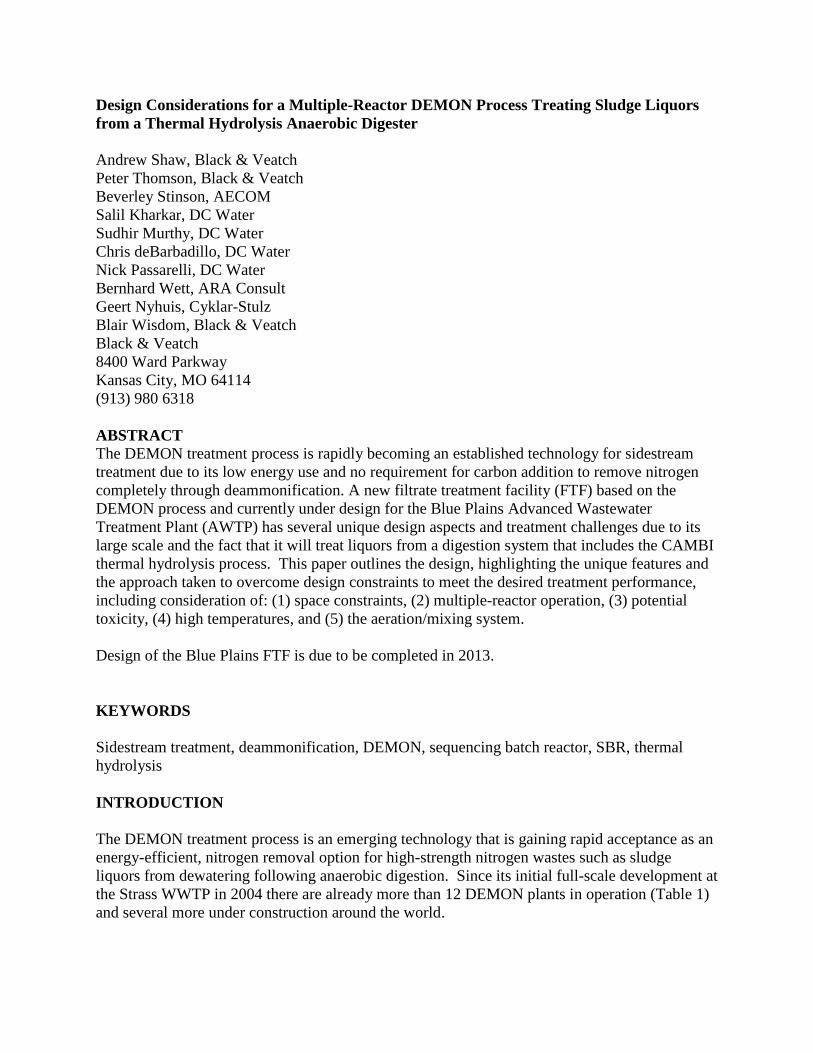
Figure 1 is an aerial view of the Blue Plans AWTP showing the proposed location for the new
DEMPON FTF in orange and the new anaerobic digesters, CAMBI and combined heat and
power (CHP) system indicated in green.
Figure 1: Aerial Photograph of Blue Plains AWTP Showing Proposed Location of the New
DEMON FTF (orange) and New Digesters, CAMBI and CHP (green).
Almost all DEMON facilities are single sequencing batch reactors (SBR) or dual reactors which
operate autonomously (i.e. they have their own individual blowers and feed pumps). However,
the Blue Plains facility will have an estimated filtrate flow of 4,200 m3/d (1.1 mgd) and liquor
ammonia-nitrogen concentrations of up to 3000 mg/L to give a loading up to 12,600 kgN/d
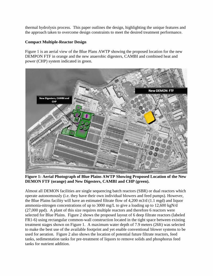
(27,000 ppd). A plant of this size requires multiple reactors and therefore 6 reactors were
selected for Blue Plains. Figure 2 shows the proposed layout of 6 deep filtrate reactors (labeled
FR1-6) using rectangular common-wall construction located in the tight space between existing
treatment stages shown on Figure 1. A maximum water depth of 7.9 meters (26ft) was selected
to make the best use of the available footprint and yet enable conventional blower systems to be
used for aeration. Figure 2 also shows the location of potential future filtrate reactors, feed
tanks, sedimentation tanks for pre-treatment of liquors to remove solids and phosphorus feed
tanks for nutrient addition.
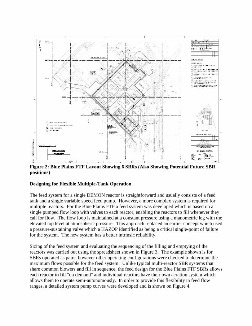
Figure 2: Blue Plains FTF Layout Showing 6 SBRs (Also Showing Potential Future SBR
positions)
Designing for Flexible Multiple-Tank Operation
The feed system for a single DEMON reactor is straightforward and usually consists of a feed
tank and a single variable speed feed pump. However, a more complex system is required for
multiple reactors. For the Blue Plains FTF a feed system was developed which is based on a
single pumped flow loop with valves to each reactor, enabling the reactors to fill whenever they
call for flow. The flow loop is maintained at a constant pressure using a manometric leg with the
elevated top level at atmospheric pressure. This approach replaced an earlier concept which used
a pressure-sustaining valve which a HAZOP identified as being a critical single-point of failure
for the system. The new system has a better intrinsic reliability.
Sizing of the feed system and evaluating the sequencing of the filling and emptying of the
reactors was carried out using the spreadsheet shown in Figure 3. The example shown is for
SBRs operated as pairs, however other operating configurations were checked to determine the
maximum flows possible for the feed system. Unlike typical multi-reactor SBR systems that
share common blowers and fill in sequence, the feed design for the Blue Plains FTF SBRs allows
each reactor to fill "on demand" and individual reactors have their own aeration system which
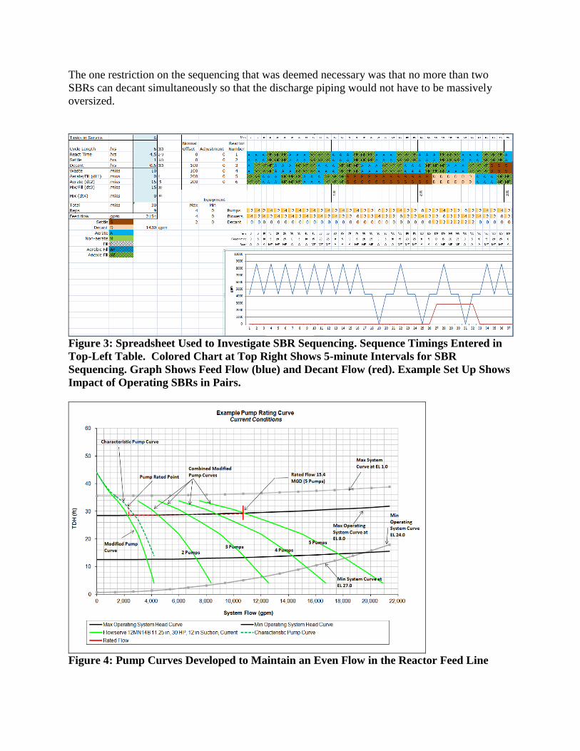
allows them to operate semi-autonomously. In order to provide this flexibility in feed flow
ranges, a detailed system pump curves were developed and is shown on Figure 4.
The one restriction on the sequencing that was deemed necessary was that no more than two
SBRs can decant simultaneously so that the discharge piping would not have to be massively
oversized.
Figure 3: Spreadsheet Used to Investigate SBR Sequencing. Sequence Timings Entered in
Top-Left Table. Colored Chart at Top Right Shows 5-minute Intervals for SBR
Sequencing. Graph Shows Feed Flow (blue) and Decant Flow (red). Example Set Up Shows
Impact of Operating SBRs in Pairs.
Figure 4: Pump Curves Developed to Maintain an Even Flow in the Reactor Feed Line
Designing for Potential Toxicity
Pilot testing was carried out to test removal rates for sludge liquors from a CAMBI system in
order to determine if the DEMON process would be inhibited by them (Figdore, 2011). It was
found that significant inhibition did occur, most notably to the AOBs, but that diluting the
CAMBI liquors 1:1 with plant water reduced the inhibition to an acceptable level that enabled
the DEMON process to remove ammonia at a volumetric loading rate of 0.6 kgN/m3/d. A
dilution system using plant water (plant effluent) was included in the FTF design to facilitate
this.
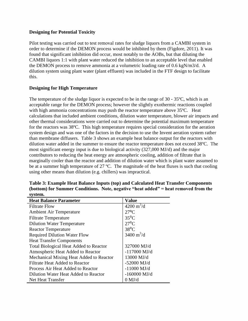
Designing for High Temperature
The temperature of the sludge liquor is expected to be in the range of 30 - 35ºC, which is an
acceptable range for the DEMON process; however the slightly exothermic reactions coupled
with high ammonia concentrations may push the reactor temperature above 35ºC. Heat
calculations that included ambient conditions, dilution water temperature, blower air impacts and
other thermal considerations were carried out to determine the potential maximum temperature
for the reactors was 38ºC. This high temperature requires special consideration for the aeration
system design and was one of the factors in the decision to use the Invent aeration system rather
than membrane diffusers. Table 3 shows an example heat balance output for the reactors with
dilution water added in the summer to ensure the reactor temperature does not exceed 38ºC. The
most significant energy input is due to biological activity (327,000 MJ/d) and the major
contributors to reducing the heat energy are atmospheric cooling, addition of filtrate that is
marginally cooler than the reactor and addition of dilution water which is plant water assumed to
be at a summer high temperature of 27 ºC. The magnitude of the heat fluxes is such that cooling
using other means than dilution (e.g. chillers) was impractical.
Table 3: Example Heat Balance Inputs (top) and Calculated Heat Transfer Components
(bottom) for Summer Conditions. Note, negative “heat added” = heat removed from the
system.
Heat Balance Parameter Value
Filtrate Flow 4200 m3/d
Ambient Air Temperature 27⁰C
Filtrate Temperature 35⁰C
Dilution Water Temperature 27⁰C
Reactor Temperature 38⁰C
Required Dilution Water Flow 3400 m3/d
Heat Transfer Components
Total Biological Heat Added to Reactor 327000 MJ/d
Atmospheric Heat Added to Reactor -117000 MJ/d
Mechanical Mixing Heat Added to Reactor 13000 MJ/d
Filtrate Heat Added to Reactor -52000 MJ/d
Process Air Heat Added to Reactor -11000 MJ/d
Dilution Water Heat Added to Reactor -160000 MJ/d
Net Heat Transfer 0 MJ/d

Aerator/Mixer Design
A detailed assessment of different aeration system options was carried out. Ultimately it was
determined that the Invent Mixer/Aerator provided several benefits over a conventional diffused
aerator system, including: combined mixing/aeration functionality which gives good control of
the intermittently aerated SBRs; robust performance at high temperatures; lower maintenance
costs; ease of installation. Figure 5 is a schematic showing the main components of the invent
Mixer/Aerator and Figure 6 is a photograph of an example installation. Figure 7 is the proposed
layout for four 30kW (40hp) mixer/aerators with provision made for a possible fifth unit if
required in the future. In the mixing mode, the units will run at a slow speed, drawing
approximately 6.3kW (8.5 hp); in the aeration mode, air will be provided to the ring sparger
beneath the mixer/aerator by high-speed gearless turbo blowers and the unit will be run at a
higher speed.
Figure 5: Invent Mixer/Aerator Schematic (courtesy Invent)
Figure 6: Example Installation Photograph
for an Invent Mixer/Aerator System
(courtesy Invent)
Figure 7: Proposed Layout of
Invent Mixer/Aerators for the FTF

SUMMARY
The DEMON process is gaining in popularity and has rapidly become an established process
option for sidestream treatment. The DEMON plant proposed for the Blue Plains FTF was the
largest of its kind and the first to treat liquors from a CAMBI thermal hydrolysis system when it
was conceived. This has resulted in some unique design features including consideration of:
1. Space constraints
2. Multiple-reactor operation
3. Potential toxicity
4. High temperatures
5. Aeration/mixing system
Table 3 summarizes the FTF design parameters, noting the constraints and comments described
in more detail in the previous sections of this paper.
The design is due to be completed in 2013 with construction and commissioning starting soon
after. In parallel with the design, pilot testing is being conducted to investigate inhibition and
temperature effects using liquors generated from Blue Plains sludge.
REFERENCES
Figdore, B., Wett, B., Hell, M. and Murthy, S. (2011) “Deammonification of Dewatering
Sidestream from Thermal Hydrolysis-Mesophilic Anaerobic Digestion Process” Proceedings of
WEFTEC 2011
Neethling, J.B. (2012) “Deammonification Compendium” Water Environment Research
Foundation Report, December 2012

Table 3: Design Parameter Summary
Values Constraints/Comments
Flow 4200 m3/d (1.1 mgd) Design flow estimated from sludge
production and limiting ammonia
concentration in digesters to 3000
mg/L using dilution of Cambi treated
sludge.
Reactor Dimensions Number of reactors: 6
Length: 24.38 m (80 ft)
Width: 18.29 m (60ft)
Maximum SWD: 7.93 m (26ft)
Minimum SWD: 6.71 m (22ft)
Small-footprint available, therefore
deep tanks used. Depth limited to
enable normal blowers to be used.
Loading 0.6 kgN/m3.d (0.0375 lb/d/ft
3) Typical loading for DEMON is 1.0
kgN/m3.d, however toxicity concerns
require a reduced loading.
Acclamation may enable higher
loadings to be achieved than current
design values. Further pilot testing to
be conducted to check this.
Temperature Maximum 38°C Dilution water is plant effluent with a
temperature of 27°C in the summer.
Cooling of the reactors to 38°C is
feasible with a reasonable dilution of
up to 2.5 times the influent flow.
Aeration System Invent Mixer/Aerator
4x30kW (40 hp) Units
AOR = 404 kg/h (890 pph)
during aeration cycle
High temperatures and mixing
requirements for granular sludge,
amongst other factors made diffused
aeration less favorable than the Invent
system. Required AOR depends on
aeration period time and overall SBR
sequence timings. Longer cycles =
lower AOR but limits the flow of
filtrate that can be treated.
Feed System Max loop flow: 3600 m3/hr
(16000 gpm)
Minimum loop flow: 110
m3/hr (470 gpm)
The need to be able to feed up to 6
SBRs simultaneously over a wide
range of dilutions creates a wide range
of flows that have to be
accommodated by the feed flow loop
Equalization/Dilution Dilution range for inhibition
1:1
Dilution range for cooling:
2.5:1
Feed tank volume:
(0.58 MG)
2.5 times the influent flow maximum
available for temperature control.
Flows in excess of this would require
multiple decanters in the SBRs to
handle the extra flow.