design considerations for mine workings under accumulation...
TRANSCRIPT

In ' temtionaZ Joumzal of Mine Water, 4 ( 1 983) 35 - 56 P r i n t e d i n Granada, Spain
DESIGN CONSIDERATIONS FOR MINE WORKINGS UNDER
ACCUMULATIONS OF WATER
R N Singh* and A S Atkins*
* Department of Mining Engineering, Univers i ty of Nottingham Un ive r s i t y Park, Nottingham NG7 2RD UK
** Department of Mining Engineering, North Staffo:dshire Poly technic , College Road, Stoke on T ren t , S t a f f o r d s h i r e , UK
ABSTRACT
The s tudy o u t l i n e s t h e e f f e c t s of s u r f a c e and underground subsidence p a t t e r n s on t h e s p a t i a l d i s t r i b u t i o n of i n - s i t u permeabi l i ty and i t s e f f e c t s on groundwater inflow. The behaviour of s t r a t a surrounding a longwall f a c e where l im i t ed knowledge e x i s t s has been ou t l i ned . The e f f e c t s of mining subsidence on t h e su r f ace f low p a t t e r n have been descr ibed w i th t h e remedial so lu t i ons . The mechanism of formation of s inkholes i n c e r t a i n chemical rockmass has been descr ibed . Factors a f f e c t i n g mine water i n£ low have been descr ibed i n d e t a i l with t h e a i d of a s imp l i f i ed conceptual model and ca se s t ud i e s . P r a c t i c a l examples of undersea workings and those under a l a rge accumulation of water a r e given, both i n t h e United Kingdom and worldwide.
INTRODUCTION
Mining under accumulations of water inc lude workings under sea, lakes , e s t u r a r i e s , r i v e r s , s treams, ponds, underground aqu i f e r s , abandoned n i n e workings and unconsolidated s u r f a c e depos i t s l i a b l e t o l i q u i f a c t i o n . I n o rde r t o maximize t h e percentage e x t r a c t i o n ( 5 2 percent i n UK) i t i s important t h a t f o r f u t u r e mining u n d e r bodies of water , a t t e n t i o n should be given t o t h e d e t a i l e d design of such workings [I]. An economical assessment should be made f o r provid ing p r o t e c t i v e p i l l a r s , consequently s t e r i l i z i n g r e se rves , versus c o s t of pumping inf low water during t he e n t i r e l i f e of a mine. It i s impera t ive t h a t damage t o l i f e and app rec i ab l e l o s s of proper ty i s no t compromised.
EFFECTS OF M I N I N G ON IN-SITU PERMEABILITY CHANGES AND GROUNDWATER INFLOW
The underground mining modif ies s u r f a c e and underground flow p a t t e r n which may a f f e c t groundwater hydrology and mining ope ra t i ons i n one of t h e fo l lowing ways:
( i ) mining subsidence changing t h e su r f ace f low p a t t e r n and water t a b l e ;

( i i ) under c e r t a i n c o n d i t i o n s , promote f o r m a t i o n of s i n k h o l e s ; and
( i i i ) c a u s e s e r i o u s w a t e r i n f l o w problems t o a mine.
S u r f a c e Subs idence P a t t e r n
Underground mining c a u s e s r e d i s t r i b u t i o n of s t r a t a s t r e s s e s r e s u l t i n g i n underground and s u r f a c e subs idence . F i g . 1 shows components o f ground movements a t t h e s u r f a c e a s a consequence of t o t a l e x t r a c t i o n . Three d i s t i n c t zones of s u b s i d e n c e a r e a p p a r e n t which a r e a s f o l l o w s [ 2 1
( i ) zone of f u l l subs idence ; ( i i ) zone of compression; and ( i i i ) zone of e l o n g a t i o n
slop. cur.. b l
?roa"<"... - .L&
E
"I a -, ;i
- 4
(s)S.bsr.tlcol radlh of enlrortmn
(c) Sup.rcnt*cal wodlh d e r t r r c l l o n
F i g . 1 Component of ground movement a t t h e s u r f a c e due t o t o t a l e x t r a c t i o n

With reference to Fig. 1 the zone of full subsidence develops when the width of extraction exceeds 1.4D and is characterized by only vertical displacement of ground surface. The zone of elongation is bounded by a line vertically above the panel edge and the limiting angle inter- secting the surface (UK average value 55'). This zone is characterized by development of horizontal tensile strains inducing surface fractures, which are known to extend up to 15 metres in depth. The zone of compre- ssion which lies between the zone of subsidence and the zone of elonga- tion is characterized by horizontal compressive strains and reduction in water inflow.
Underground Subsidence Pattern
Fig. 2 shows a schematic presentation of underground subsidence associated with mining which is characterized in three distinct zones as follows:
(i) zone of vertical compression; (ii) zone of vertical extension; (iii) zone of incomplete convergence.
The zone of vertical extension lies immediately above the central zone of extraction and is caused by caving of waste as a consequence of extraction and is the result of volume expansion from caving. The vertical subsidence at the surface (in the zone of full subsidence Fig. 1) is less than the height of extraction (surface subsidence ranges between 40-90% of seam extraction). At the centre of extraction, the floor heave is more pronounced and tapers towards the edge of extraction At this point the vertical closure is minimum because of contraint provided by the pillar edge.
Undersea working limited to lOmm/m
Original surface
4 -
compression
Vertical
Fie. 2 Schematic De~iction of Stress Zones in Underground Mining
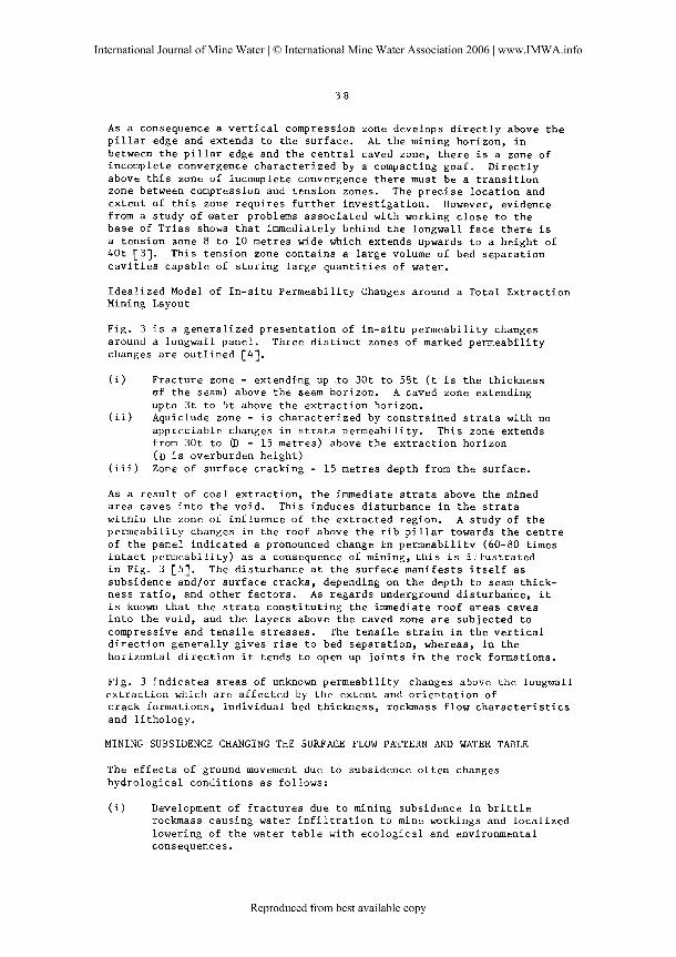
As a consequence a vertical compression zone develops directly above the pillar edge and extends to the surface. At the mining horizon, in between the pillar edge and the central caved zone, there is a zone of incomplete convergence characterized by a compacting goaf. Directly above this zone of incomplete convergence there must be a transition zone between compression and tension zones. The precise location and extent of this zone requires further investigation. However, evidence from a study of water problems associated with working close to the base of Trias shows that immediately behind the longwall face there is a tension aone 8 to 10 metres wide which extends upwards to a height of 40t [3). This tension zone contains a large volume of bed separation cavities capable of storing large quantities of water,
Idealized Model of In-situ Permeability Changes around a Total Extraction Mining Layout
Fig. 3 is a generalized presentation of in-situ permeability changes around a longwall panel. Three distinct zones of marked permeability changes are outlined [41.
(i) Fracture zone - extendkng up to 30t to 58t (t is the thickness of the seam) above the seam horizon. A caved zone extending upto 3t to 5t above the extraction horizon.
(ii) Aquiclude zone - is characterized by constrained strata with no appreciable changes in strata permeability. This zone extends from 30t to (D - 15 metres) above the extraction horizon ( D is overburden height)
(iii) Zone of surface cracking - 15 metres depth from the surface.
As a result of coal extraction, the immediate strata above the mfned area caves into the void. This induces disturbance in the strata within the zone of influence of the extracted region. A study of the permeability changes in the roof above the rib pillar towards the centre of the panel indicated a pronounced change in permeability (60-80 times intact ~ermeability) as a consequence of mining, this is illustrated in Fig. 3 [51. The disturbance at the surface manifests itself as subsidence and/or surface cracks, depending on the depth to seam thick- ness ratio, and other factors. As regards underground disturbance, it is known that the strata constituting the immediate roof areas caves into the void, and the layers above the caved zone are subjected to compressive and tensile stresses. The tensile strain in the vertical direction generally gives rise to bed separation, whereas, io the horizontal direction it tends to open up joints in the rock formations.
Fig. 3 indicates areas of unknown permeability changes above the longwall extraction which are affected by the extent and orientation of crack formations, individual bed thickness, rockmass flow characteristics and lithology.
MINING SUBSIDENCE CHANGING THE SURFACE FLOW PATTERN AND WATER TABLE
The effects of ground movement due to subsidence often changes hydrological conditions as follows:
(i) Development of fractures due to mining subsidence in brittle rockmass causing water infiltration to mine workings and localized lowering of the water table with ecological and environmental consequences.
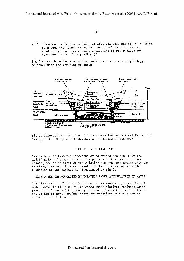
(ii) Subsidence effect on a thick plastic bed rock may be in the forn of a deep subsidence trough without development of water conducting fracture, causing outcroping of water table and consequently, surface pending [6].
Fig.4 shows the effects of mining subsidence on surface hydrology together with the remedial measures.
Surface cracks a 0 Transition zones between Zone of increased to subsidence compression & tenston zone
\ / \ \ / \ Water 7------ - - - -
- 7 - - - - Suit- rock t- . trough
CRACKING
L ZONE t
I
-
Aquiclude Zone
(D-15 to30t)
Ji- I
+ r r L t
ts-t ofextraction \ / +-- h . T h i d t m of fractured zone Tenalle zone containing bed D.D.pth ofcover separation cavities
Fig.3. Generalized Depiction of Strata Behaviour with Total Extraction ?.lining (after Singh and Kendorski, and modified by authors)
FORMATION OF SINKHOLES
Mining beneath fissured limestone or dolomites can result in the modification of groundwater inflow pattern to the mining horizon causing the enlargement of the existing fissures and caving into the existing caverns. This can result in the formation of sinkholes extending to the surface as illustrated by Fig.5.
MINE WATER INFLOW CAUSED BY WORYINGS UNDER ACCU?fLJT.,ATION OF WATER
The mine water inflow variables can be represented by a simplified model shown in Fig.6 which indicates three distinct regimes: water, protective layer and the mining horizon. The factors which affect the design of mine workings under accumulations of water can be sumarised as follows:

(a) - Solid Stratum m l w w mlnlnq
Caved wlula
Infiltration of Groundwater Resulting from Mining Subsidence (schematic cross section)
(b) - Thick Plastic Aquifer m l o r e rn~non~ Aller mlntnp
i
- _ Plarl8c aqutler------
- - -. - - - . . - . .
Cared r a r l s
Outcropping of the Groundwater in a Subsidence Trough (schematic cross section)
Remedial Measures
Subsidence trough may cause water table to pond and may be aggrevated by surface water resulting from rainfall or melting snow.
(c) - Ponding water discharged by absorbing well or borehole into suitable rock formation.
(d) - Ponding water discharged by drains.
B c I ~ c m m l q Alter rntnlnp
Pernumbla b~ A lmncrm~able bed
L ~ a r e c waste 1
Remedial measure is to sink absorbing well or borehole into suitable receiving rock formation to drain surface water. The well drainage can also be assisted by mole or french drains.
In this case because underlying strata is impermeable de-watering techniques using a well is unsuitable. Remedial measures is to use absorbing drains and discharge into suitable water course.
F i g . 4 The E f f e c t s o f Mining Subs idence on S u r f a c e Hydrology toge ther w i t h Remedial Measures
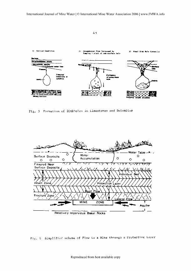
I ) In i t i a l Caditiem 2 ) Cramdvater P l w Incrmad by P-ing - start of sub-surfwe hole
Fig. 5 Formation of Sinkholes in Limestones and Dolomites
-1 MINE ZONE m a - *,,'if,
-4 - Relatively Impervious Basal Rocks
F i g . 6 Simplified scheme of Flow to a Mine through a Protective Layer
1. s i z e of b o d i e s of wate r 2 . n a t u r e o f i n t e r v e n i n g s t r a t a 3. s t r u c t u r a l d i s c o n t i n u i t i e s and g e o l o g i c a l f e a t u r e s 4. mode of s t r e s s d i s t r i b u t i o n < caved w a s t e
induced f r a c t u r e on r i b p i l l a r 5 . t h i c k n e s s o f i n t e r v e n i n g s t r a t a 6 . wa te r p r e s s u r e .
S i z e of b o d i e s of w a t e r - water accumula t ion and t h e i n r u s h p o t e n t i a l
( i ) I n t h i s c o n t e x t , wa te r b o d i e s can b e d i v i d e d i n t o t h r e e c a t e g o r i e s depending upon t h e p o t e n t i a l i n t e n s i t y of a n i n r u s h and summar- i s e d a s f o l l o w s :
o c a t a s t r o p h i c - which may p o s e t h r e a t of d e s t r u c t i o n i n t h e mine, should t h e r e be an i n r u s h . It i n c l u d e s oceans , l a r g e l a k e s , r i v e r s underground a q u i f e r s , s o l u t i o n c a v i t i e s , bed s e p a r a t i o n c a v i t i e s , u n d e r g r o u n d abandoned mine workings and u n c o n s o l i d a t e d s u r f a c e d e p o s i t l i a b l e t o l i q u i f a c t i o n .
o Major - t h o s e w i t h major p o t e n t i a l danger would i n c l u d e l a k e s s t r e a m s and a q u i f e r s which might p r e s e n t a danger t o b o t h l i f e and p r o p e r t y i f a d e q u a t e d e s i g n c o n s i d e r a t i o n s a r e n o t s p e c i f i e d d u r i n g t h e mine p l a n n i n g s t a g e .
o Minor - f i n i t e b o d i e s of w a t e r w i t h a volume c o n s i d e r a b l y s m a l l e r t h a n t h e mine volume which c a n o f f e r a l i m i t e d p o t e n t i a l f o r mine damage i n t h e c a s e o f a n i n r u s h .
For an i n r u s h t o occur i t i s n e c e s s a r y t h a t t h e f o l l o w i n g c o n d i t i o n s a r e s i m u l t a n e o u s l y s a t i s f i e d :
a l a r g e accumula t ion of wate r o r f l u i d ; a p r e s e n c e of low r e s i s t a n c e r o u t e from t h e accumula t ion t o t h e mine workings; t h e h y d r a u l i c p r e s s u r e should exceed t h e t h r e s h o l d p r e s s u r e t o cause i n r u s h .
( i i ) Types o f R e s e r v o i r s Prov id ing I n r u s h P o t e n t i a l
Aquifers - i n some f o r m a t i o n s such a s s a n d s t o n e s l a r g e q u a n t i t i e s o f w a t e r can b e s t o r e d . I n most c a s e s , i f t h e a q u i f e r i s breached , th rough mining a c t i v i t i e s , t h e i n f l o w w i l l s i g n i f i c a n t l y i n c r e a s e t o t h e mine b u t i t is u s u a l l y n o t i n s t a n t a n e o u s . T h i s can c r e a t e pumping problems which may become permanent i f t h e a q u i f e r becomes recharged .
Abandoned or Disused Workings - o l d goaves can p r o v i d e a h i g h l y permeable s t o r a g e a l e a f o r a l a r g e accumula t ion of wate r . T h i s wate r i s c a p a b l e of be ing r e l e a s e d i n s t a n t a n e o u s l y , t h u s p r o v i d i n g p o t e n t i a l c a t a s t r o p h i c danger o f an i n r u s h . Water logged s h a f t s , b o r e h o l e s o r s a t u r a t e d f i s s u r e s connec ted t o f looded workings may p r o v i d e f u r t h e r danger because of an i n c r e a s e i n h y d r a u l i c head. Hydrau l ic f i l l s a s used i n m e t a l l i f e r r o u s mining may a l s o become f l u i d i z e d and a g g r e v a t e t h e s i t u a t i o n . The e x i s t a n c e of u n c h a r t e r e d o l d workings a r e a l s o p o t e n t i a l s o u r c e s of danger.

Old goaves c o n t a i n contaminated water which can be chemica l ly ana lysed t o a s c e r t a i n t h e o r i g i n of t h e mine water .
Water s t o r a g e capac i t y of abandoned underground workings can be ca l cu - l a t e d a s f o l l ows [ 7 3 :
Quant i ty of water s t o r e d i n an o l d abandoned working i s g iven by:
where
A = p l an a r e a of t he o l d workings ( e x t r a c t e d mL) M = t h i cknes s of e x t r a c t i o n (m) a = i n c l i n a t i o n of t h e seam C = c o e f f i c i e n t of compaction of a goaf - (C = 0.125 f o r t o t a l longwall
e x t r a c t i o n f o r a 1.8 m e x t r a c t i o n (UK v a l u e s ) ) \ = q u a n t i t y of water (m3)
Table 1 - C Values f o r d i f f e r e n t types of mining systems
Solut ion - So lu t i on c a v i t i e s a r e formed i n c e r t a i n format ions l i k e dolomites o r l imes tone when t h e water p e r c o l a t i n g through them i s s l i g h t l y a c i d i c and capable of d i s so lv ing rock. Consequently, l a r g e i n t e r connec t ed caverns a r e formed which a r e capable of r e l e a s i n g water r ap id ly . F ig . 7 i l l u s t r a t e s West Dr i e fon t e in Mine, S . Afr ica i n which s o l u t i o n c a v i t i e s connected by f i s s u r e s i n t e r c e p t e d t h e mine working caus ing a c a t a s t r o p h i c i n ru sh [83.
1
2
3
Bed separation envities - I n t h e Coal Measures, p a r t i c u l a r l y below an unconformity a t t h e base of T r i a s , t en s iona l zones a r e developed above t he margin of t h e longwall panels [3]. These t e n s i o n a l zones a r e c h a r a c t e r i s e d by a s e r i e s of beams of uniform th i cknes s of sands tone o r coa l , where bed s epa ra t i on c a v i t i e s a r e developed and s t r a t a pe rmeab i l i t y i s g r e a t l y i nc r ea sed . These c a v i t i e s a r e capable of s t o r i n g s i z e a b l e q u a n t i t i e s of water i f recharged by an a q u i f e r . The mechanism which causes t h e water he ld i n bed s e p a r a t i o n c a v i t i e s t o be suddenly r e l ea sed i s n o t known but could be a t t r i b u t e d t o a combination of f a c t o r s such a s minor f a u l t s , increased j o i n t s developments o r f a c i e s changes i n roof s t r a t a 1 9 1 .
Type of Workings
Sho r t wal l
Longwall t o t a l e x t r a c t i o n
Sand f i l l e d goaves
C
0.438
0 . 4 8 5 ~ -0'00205
0.275e -0.0147 p
p = s t r a t a p r e s s u r e s -

Appr ox point of inflow
13.5 pump chamber 1'
Fig. 7 Section Showing Solution Cavities and Fissure Formation at West Driefontein Mine, S. Africa (after Cousens and Garrett 1969)
t 8 1 Surface accmZat ion - This includes sea, oceans, lakes, rivers, unconsolidated deposits liable to liquifaction and tailing dumps. In the Mufulira mine in Zambia, subsidence effects Zrom mine workings resulted in an inundation of the mine by the liquifacted tailings [I01
Na~ure of the Intervening Strata
Rockmass lithology has a significant influence on the design thickness of the protective layer between the water accumulation and mine workings. In general, coal measures strata consist of successive beds of sandstone, coal, mudstone, siltstone, shales and seatearth.
In in tac t state the sandstone and coal beds may formulate aquifers, capable of storing and transmitting water. However, mudstones, shales and seatearths are relatively impervious to water flow and therefore, form ~ . i c Z u d e . These beds of adequate thickness should, therefore, be included while designing a protective layer.

Coal Measures rock i nc lud ing s h a l e , mudstone and s e a t e a r t h s , when i n t e r c e p t e d e i t h e r by naturaZ cracks cnd.f<ssures o r incluced mining, f r a c t u r e s can t r an smi t and s t o r e l a r g e volumes of water . However, t h e f r a c t u r e d coa l measures, p a r t i c u l a r l y coa l , s h a l e , mudstone and s e a t e a r t h can be conso l i da t ed under h igh d i f f e r e n t i a l s t r e s s and can v i r t u a l l y prevent water inflow. Rockmass l i t h o l o g y a l s o p l ays an impor tan t r o l e i n c o n t r o l l i n g o r fiomoting t h e formation of bed s epa ra t i on c a v i t i e s which can s t o r e l a r g e q u a n t i t i e s of water r 3 1 .
A t h i c k s t r o n g massive sands tone bed p r e sen t s cons ide r ab l e d i f f i c u l t y i n t h e format ion of roof beams and consequently p r even t s t h e development of bed s e p a r a t i o n p lanes .
A weak o r t h i n l y bedded rock may e a s i l y form bed s epa ra t i on c a v i t i e s , thus s t o r i n g l a r g e q u a n t i t i e s of water .
Thus, rockmass l i t ho logy , t h i cknes s of c a rbon i f e r rous cover, t h i cknes s of t o t a l cover and i n p a r t i c u l a r percentage of sands tone i n t h e v i c i n i t y of mine workings w i th in a l i m i t i n g he igh t of 45 m a r e thought t o be s i g n i f i c a n t con t r i bu t i ng f a c t o r s c o n t r o l l i n g mine water inflow.
S t r u c t u r a l D i s c o n t i n u i t i e s and Geological Fea tu r e s
The i nc idence of water through a p r o t e c t i v e l aye r has o f t e n been a s s o c i a t e d w i th s t r a t a d i s c o n t i n u i t i e s and o t h e r geo log i ca l f e a t u r e s such a s f a u l t s and dykes. I n coa l measures, j o i n t s a r e u n i v e r s a l l y p r e sen t and have a h igh ly v a r i a b l e geometr ica l o r i e n t a t i o n and s p a t i a l d i s t r i b u t i o n , depending on t h e type of rock, t h i cknes s of beds, geolog- i c a l age , depth , geo log i ca l s t r e s s e s and s t r e s s h i s t o r y . I n c o a l mining few new c r acks a r e formed due t o t h e mining ope ra t i ons , most of t h e subs idence occurs bg movements a long p r e - ex i s t i ng j o i n t s and cracks . A minimum of 35 x 15- m opening i s r equ i r ed f o r water t o t ransmi t through t h e j o i n t s . The j o i n t s may have rough, i n t e i l o c k i n g o r s l icke l l - s ided s u r f a c e s o r they may be coa ted with f i l l i n g m a t e r i a l s , t hus a l t e r - ing t h e i r f low c h a r a c t e r i s t i c s [43.
C h a r a c t e r i s t i c s of j o i n t s i n sedimentary rocks a r e :
o spac ing o f t e n depends on l i t ho logy , bed t h i cknes s and rock mass s t r e n g t h . I n coa l measures spacing of 0.3 t o 1 m i s common.
o J o i n t s i n s h a l e a r e inconspicuous but sha l e s may develop c l o s e l y spaced j o i n t s near t h e su r f ace .
o I n a l t e r n a t i n g sands tone-sha le sequences, j o i n t s a r e gene ra l l y b e t t e r developed i n t h e sands tones and may be confined t o i t .
Igneous dykes o f t e n i n t e r c e p t rock formations a s soc i a t ed wi.th heav i l y watered hor izons o r water s a t u r a t e d c a v i t i e s and consequently, f e ede r s of water may be encountered i f t h e mining ope ra t i ons a r e c a r r i e d ou t i n t h e i r c l o s e proximity [93.
Small f a u l t s having throws ranging up t o l m very r a r e l y p r e sen t water problems. However, when water i s encountered, t h e water make tends t o be g r e a t e s t i n t h e v i c i n i t y of any f a u l t . Increased water danger i s apparent where mine workings approach o r encounter f a u l t s p a r a l l e l t o t h e f a c e l i n e , f a u l t s which hade over workings, f a u l t s of i nc r ea s ing
throw and large faults where strata disruption and dislocation is greatest.
In the UK water problems in the undersea workings have been more pronounced in the vicinity of the geological features such as swalley banks, areas of rapidly increasing dip, monoclinal structures, lenticular sandstones, incrop to the Permian or major sandstone aquifers and massiv6 aquiferous ro6f sandstones [ 9 ] .
Modes of Stress Distribution
(a) Caved Waste
The natural stress field in the strata is mainly due to the overlying rocks, though some areas have reported active geological horizontal stress. The creation of a void in the strata by underground mining produces a disturbance in the natural stress field. The effect of the stress change results in strata deformation which, depending on the dimensions of the excavation, can extend it to the surface causing it to subside.
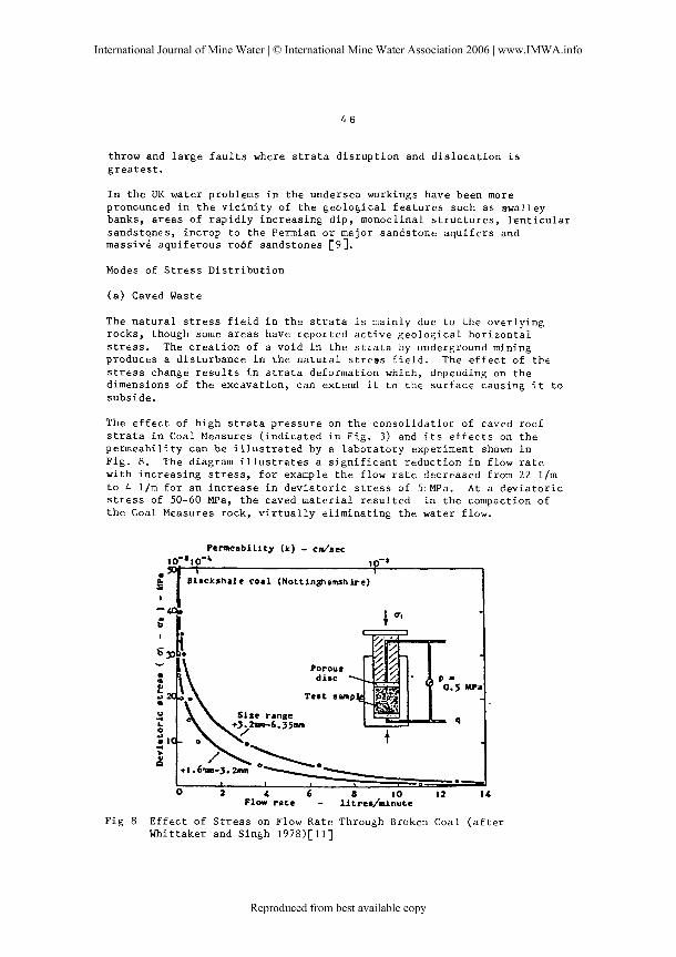
The effect of high strata pressure on the consolidatior of caved roof strata in Coal Measures (indicated in Fig. 3) and its effects on the permeability can be illustrated by a laboratory experiment shown in Fig. 8. The diagram illustrates a significant reduction in flow rate with increasing stress, for example the flow rate decreased from 22 l/m to 4 l/m for an increase in deviatoric stress of 5:MPa. At a deviatoric stress of 50-60 MPa, the caved material resulted in the compaction of the Coal Measures rock, virtually eliminating the water flow.
--I ~ i a c k r h a l e c o a l (Not t inp lamshire ) '
T e s t s m ~
Flow r a t e - litrsr/ai~ute
Fig 8 Effect of Stress on Flow Rate Through Broken Coal (after Whittaker and Singh 1978)[111
The implication of this result is that in the caved consolidated waste under confining stress the permeability will decrease depending upon the level of deviatoric stress. If it was possible to increase the deviatoric stress to 50-60 MPa, theoretically, the inflow to the mintng panel could be virtually eliminated.
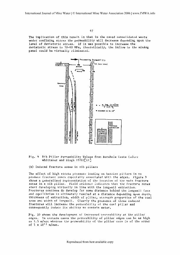
Fig. 9 Rib Pillar Permeability Values from Borehole Tests (after Whittaker and Singh 1978)[11]
(b) Induced fracture zones in rib pillars
The effect of high strata pressure loading on barrier pillars is to produce fracture zones especially associated with the edges. Figure 9 shows a generalised representation of the location of the main fracture zones in a rib pillar. Field evidence indicates that the fracture zones start developing virtually in line with the longwall extraction. Fractures continue do develop for some distance behind the longwall face and equilibrium is ultimately reached at a distance depending upon depth, thickness of extraction, width of pillar, strength properties of the coal seam and width of longwall. Clearly the presence of these induced fractures will increase the permeability of the coal pillar and consequently reduce its ability to contain water.
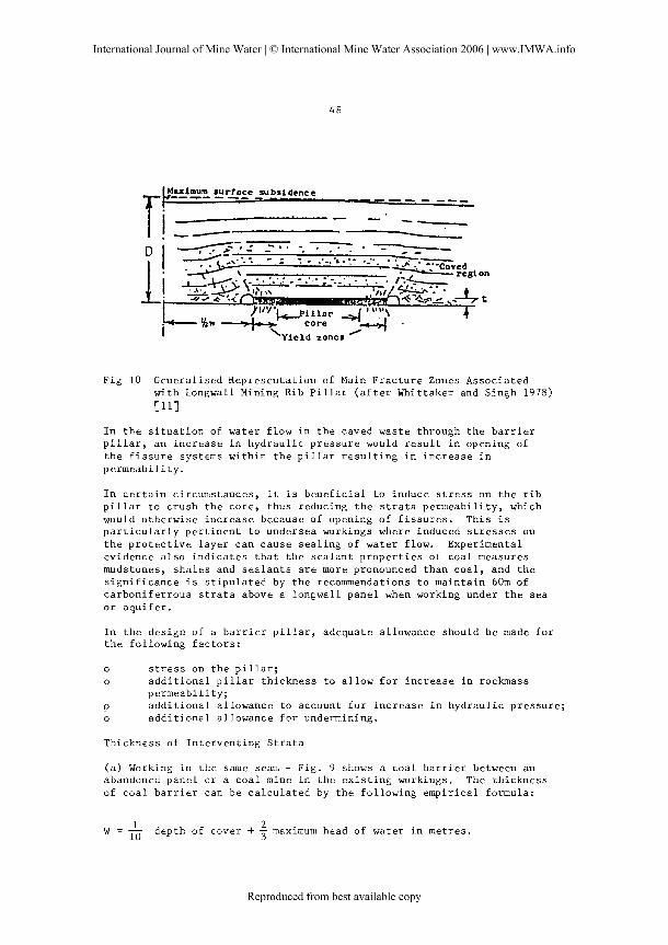
Fig. 10 shows the development of increased permeability at the pillar edges. In certain cases the permeability of pillar edges can be as high as 1.5 m/sec whereas the permeability of the pillar core is of the order of 2 x 10⁻¹ m/sec.
hlaximurn surface j u s i dence TI---- --- . - - - - ---
Fig 10 Generalised Representation of Main Fracture Zones Associated with Longwall Mining Rib Pillar (after Whittaker and Singh 1978)
[Ill
In the situation of water flow in the caved waste through the barrier pillar, an increase in hydraulic pressure would result in opening of the fissure systems within the pillar resulting in increase in permeability.
In certain circumstances, it is beneficial to induce stress on the rib pillar to crush the core, thus reducing the strata permeability, which would otherwise increase because of opening of fissures. This is particularly pertinent to undersea workings where induced stresses on the protective layer can cause sealing of water flow. Experimental evidence also indicates that the sealant properties of coal measures mudstones, shales and sealants are more pronounced than coal, and the significance is stipulated by the recommendations to maintain 60m of carboniferrous strata above a longwall panel when working under the sea or aquifer.
In the design of a barrier pillar, adequate allowance should be made for the following factors:
o stress on the pillar; o additional pillar thickness to allow 6or increase in rockmass
permeability; P additional allowance to account for increase in hydraulic pressure; o additional allowance for undermining.
Thickness of Interventing Strata
(a) Working in the same seam - Fig. 9 shows a coal barrier between an abandoned panel or a coal mine in the existing workings. The thickness of coal barrier can be calculated by the following empirical formula:
w = A depth of cover + -$ maximum head of water in metres.
(b) Working under accumulation of water in an inland situation
In the United Kingdom the thickness of intervening strata between the mining horizon and inland accumulations of water is governed by the Mines (precautions Against Inrushes) Regulation 1979 [ 121, which specify the following minimum barrier, unless an alternative method of work has been approved by the Inapectorate.
(i) 45 m (measured in any plane) of the surface o any rock or stratum containing water or likely to contain
water o any peat, muss, sand gravel, silt or other material that flows
or is likely to flow when wet o any disused workings not being disused mine workings, or
(ii) 37 metres (measured in any plane) of any disused mine working.
(c) Undersea Workings or Major Aquifer
Prior to 1968 the various British coalfield working undersea reserves had their own individual rules based largely on Crown lease conditions which had applied at the time when the leases were administered by the Coal Commission. There were anomalies, however, in the arrangements and it was decided to standardize the rules and issue new instructions. Code of working practice 'Working under the Sea' P1/1968/8 (revised 1971) and the Mines (Precautions against Inrushes) regulation 1979 to cover the whole country [13].
These recommendations were based on the following criteria:
o past experience o subsidence considerations and experience of fractures from known
strains; u a contingency to allow for incomplete knowledge of factors.
(i) Longwall Extraction
Requires a minimum cover between the top of the seam and the sea bed of 105 m and minimum thickness of 60 m of carboniferrous strata above the top of the seam. Tensile strain at the sea bed shall not exceed 10 mm/m in both first and successive seam workings.
Fig. 11 indicates the minimum depth of cover versus extracted seam height (aggregated height) for a single or multiple seam extraction.
(ii) Room and Pillar Extraction
This shall not be carried out when the cover to the sea bed is less than 60 m and where the thickness of carboniferrous strata Is less than 45 m. The size of the pillar must not be less than 0.1 depth plus the thickness of seam if over 2 m. Depth for this purpose must include half depth of sea water.
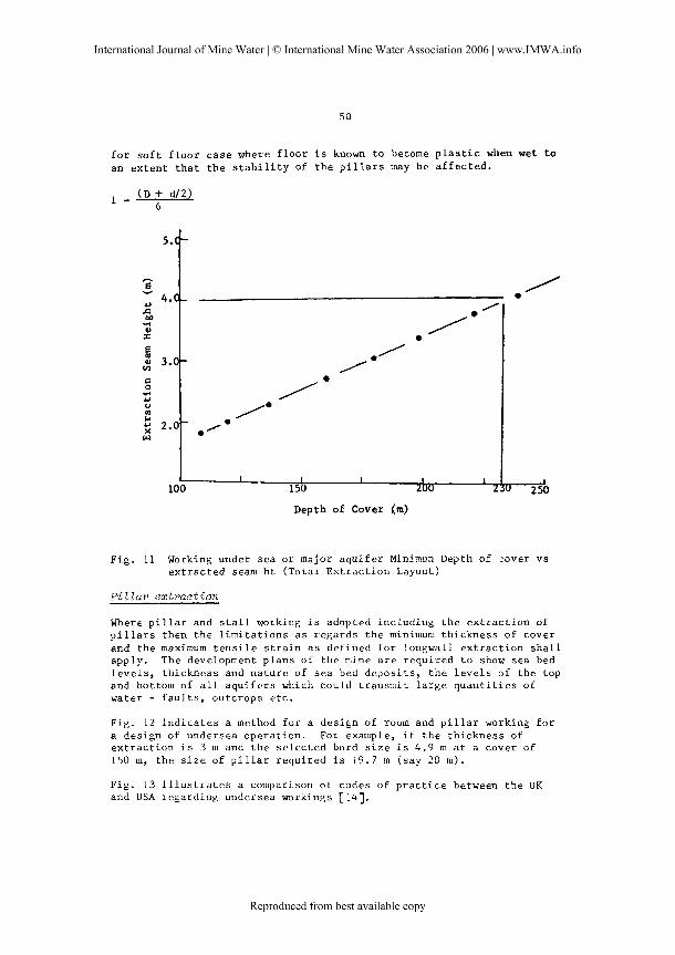
f o r s o f t f l o o r c a se where f l o o r i s known t o become p l a s t i c when wet t o an e x t e n t t h a t t h e s t a b i l i t y of t h e p i l l a r s may be a f f e c t e d .
Depth of Cover (m)
Fig . 11 Working under sea o r major a q u i f e r Minimun Depth of :over v s ex t r ac t ed seam h t (Tota l Ex t r ac t i on Layout)
Pi 2 lar extraction
Where p i l l a r and s t a l l working i s adopted i nc lud ing t h e e x t r a c t i o n of p i l l a r s then t h e l i m i t a t i o n s a s r ega rd s t h e minimum th i cknes s of cover and t h e maximum t e n s i l e s t r a i n a s def ined f o r longwall e x t r a c t i o n s h a l l apply . The development p l ans of t h e mine a r e r equ i r ed t o show sea bed l e v e l s , t h i cknes s and n a t u r e of s ea bed depos i t s , t h e l e v e l s of t h e top and bottom of a l l a q u i f e r s which could t r an smi t l a r g e q u a n t i t i e s of water - f a u l t s , ou tcrops e t c .
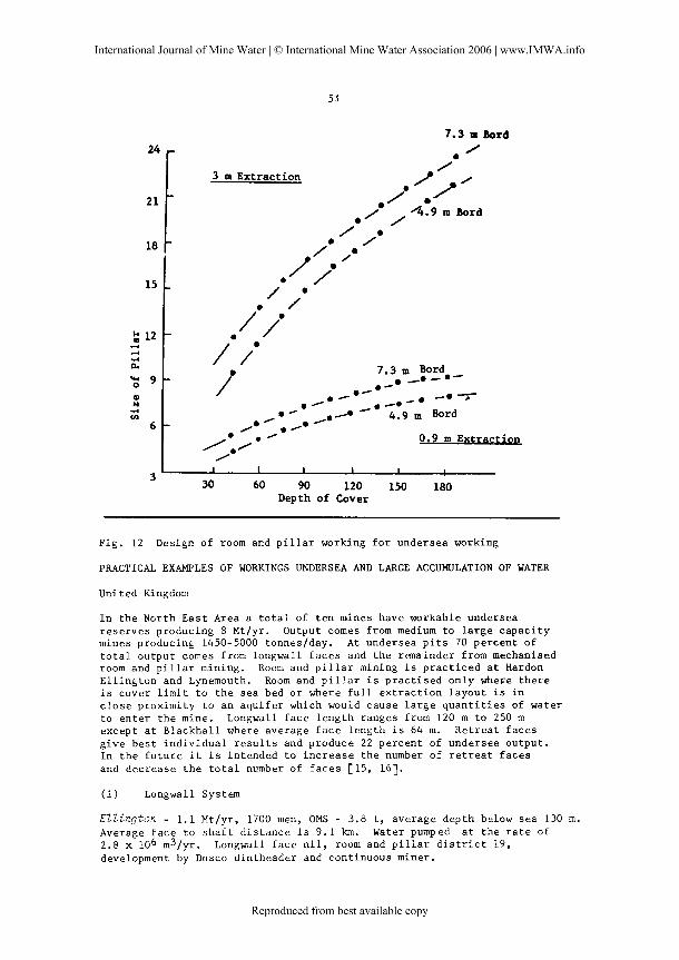
F ig . 12 i n d i c a t e s a method f o r a des ign of room and p i l l a r working f o r a des ign of undersea ope ra t i on . For example, i f t h e t h i cknes s of e x t r a c t i o n i s 3 m and t h e s e l e c t e d bord s i z e i s 4.9 m a t a cover of 150 m y t h e s i z e of p i l l a r r equ i r ed i s 19.7 m ( s ay 20 m).
F i g . 13 i l l u s t r a t e s a comparison of codes of p r a c t i c e between t h e UK and USA regard ing undersea workings [14].
3 m Extraction
. ' /. / i
I*,@
1 7.3 m Bard., - 0 - @ - -0-• - 0 7r . (* ,,-a-. . ,, -@ 4.9 m Bard
/ o O ./* e 0 0.9 m Extraction
1 t I I 1 I I
3 30 60 90 120 150 180
Depth of Cover
Fig . 12 Design of room and p i l l a r working f o r undersea working
PRACTICAL EXAMPLES OF WORKINGS UNDERSEA AND LARGE ACCUMULATION OF WATER
United Kingdom
I n t h e North E a s t Area a t o t a l of t e n mines have workable undersea r e s e r v e s p roduc ing 8 Mt/yr . Output comes from medium t o l a r g e c a p a c i t y mines producing 1450-5000 tonnes lday . At undersea p i t s 70 p e r c e n t of t o t a l o u t p u t comes from longwall f a c e s and t h e remainder from mechanised room and p i l l a r mining. Room and p i l l a r mining i s p r a c t i c e d a t Hardon E l l i n g t o n and Lynemouth. Room and p i l l a r i s p r a c t i s e d o n l y where t h e r e i s cover l i m i t t o t h e s e a bed o r where f u l l e x t r a c t i o n l a y o u t i s i n c l o s e p r o x i m i t y t o an a q u i f e r which would cause l a r g e q u a n t i t i e s of wate r t o e n t e r t h e mine. Longwall f a c e l e n g t h ranges from 120 m t o 250 m excep t a t B l a c k h a l l where average f a c e l e n g t h i s 64 m. R e t r e a t f a c e s g i v e b e s t i n d i v i d u a l r e s u l t s and produce 22 p e r c e n t of undersea o u t p u t . I n t h e f u t u r e i t i s in tended t o i n c r e a s e t h e number of r e t r e a t f a c e s and d e c r e a s e t h e t o t a l number of f a c e s [15, 161.
( i ) Longwall System
EZZington - 1 . 1 Mt/yr , 1700 men, OMS - 3.8 t , average dep th below s e a 130 m. Average f a c e t o s h a f t d i s t a n c e i s 9 . 1 km. Water pumped a t t h e r a t e of 2.8 x 10⁶ m31yr. Longwall f a c e n i l , room and p i l l a r d i s t r i c t 19, development by Dosco d i n t h e a d e r and cont inuous miner .
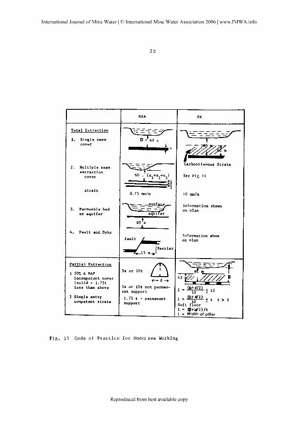
Fin . 13 Code of P r a c t i c e f o r Undersea Working
Total Extraction
1. Single seam cover
2. Multiple seam extraction cover
strain
3. Permeable bed or aquifer
4. Fault and Dyke
Partial Extraction
1 507. & R&P incompetent cover (solid - 1.75t less than above
2 Single entry competent strata
USA
~--~=;-=LL17
x
UK
x- - - - _ _ _ _ - - - - 7 - - -- --
f7-35.Xm Carbonifemus Strata
See Fig I I
8.75 m / m
- - - -
t 60 x
Fault
A a r r 1 . r +15 m +
f i 5s or lot
C s --* 59 Or lot not Perman- ent support
1.75 t - permanent support
10 w / m
Information shown on plan
Information show on plan
\--F-~?-~ ~9 45 ?<I-/ f l n V ? t 2
l a @ g q t t > 2 Soft floor 1 = @+W2)/6 1 = Width of pillar
*
Eynemouth - 0.9 Mt/yr, 1900 men, OMS - 2.4 t , average depth below s e a 125 m. Average ace t o s h a f t d i s t a n c e 7.8 km. Water pumped a t t h e d r a t e of 4.0 x 10 m31yr . Three longwall f a c e s and seven room and p i l l a r d i s t r i c t g development by Dosco d in theader , roadheader and continuous miner.
~ m d o n - 1.1 Mtlyr, 2300 meu, OMS 2.7 t . Average depth below sea 410 m. Average f ace t o s h a f t d i s t ance 3.8 km. Water pumped a t t h e r a t e of 0.3 x lo6 m31yr. F ive longwall f ace s , development by Dosco d in theader , Dosco roadheader, continuous miner, d r i l l , f i r e and machine loading.
BZackhaZl - 0 .3 Mtlyr, 1300 men, OMS 1.1 t. Average depth below sea 390 m. Average f a c e t o s h a f t d i s t a n c e 8.3 km. Water pumped a t t h e r a t e of 5.5 x lo6 m31yr. Four longwall f ace s , development by Dosco d in theader , d r i l l and f i r e and hand loading.
( i i ) Room and P i l l a r Systems
Hnrdon - - This c o l l i e r y was previous ly worked by longwall methods, however, t h e l i m i t of cover t o water bear ing s t r a t a decreased, i nc r ea s ing t h e q u a n t i t y of water make. b n g w a l l mining was abandoned f o r l e s s product ive room and p i l l a r mining systems which reduced t h e heavy f eede r of water but t he output reduced cons iderably . Attempts t o work 55 m longwall f a c e s gave good product ion but a f t e r 140 m of r e t r e a t and t h e occurence of 76 11s (1000 gpm) of water f eede r t h e f ace stopped.
Ellington and L y n e ~ u t h - Two t h i c k seams a r e worked by room and p i l l a r mining and t h i s complex i s t h e l a r g e s t undersea ope ra t i on i n t h e world.
World Wide Appl ica t ions
To ta l coa l e x t r a c t i o n under t h e sea i s being p r a c t i s e d succes s fu l l y i n many p a r t s of t h e world, inc luding Eas tern Canada, Japan, Chi le , Taiwan and t h e Sovie t Union. To ta l e x t r a c t i o n has a l s o been taking p l ace beneath r i v e r s i n Duisberg Harbour, (W Germany), River Tyne England, Lougher River Es tuary [4] and under s t o r ed water i n l a r g e dams near Sydney, A u s t r a l i a [17].
Canada - C o a l ha s been mined i n Cape Breton I s l and , Nova Sco t i a under t h e ocean f l o o r s i n c e 1720 [18 j . The p re sen t o v e r a l l production i s 2.8 m i l l i o n tonnes pe r year. Four major coa l seams a r e mined from t h e e x i s t i n g 3 mines; Bonnar Seam ( 3 m), Hub seam (2.7 m), Harbor seam (2.1 - 4.2 m) and Phalen seam (1.5 - 2.1 m) . Tota l e x t r a c t i o n i s permi t ted when t h e depth of cover i s 97 m per metre of coal ex t r ac t ed . The cover should inc lude s h a l e s and o the r impervious beds t o water.
NO. 6 Mine - Work Harbor Seam, manpower 1200, OMS 4 t , annual product ion 0.'9 m tonnes from two advancing longwall faces . Depth below ocean 756 m. Average d i s t a n c e of workings from t h e s h a f t i s 10 km. Face length 212 m equipped wi th s h i e l d suppor ts and double ended ranging drum shea re r (225 kw). Development by Dosco Roadheader o r a l t e r n a t i v e l y d r i l l i n g and b l a s t i n g and loading wi th Eimco loader.

Liman - Produces 1.4 Mt/yr from 3 advancing f ace s , 212 rn long a t a mining depth of 485 m. OMS 6.3 tonnes. Development work i s done w i th Dosco Mk I1 roadheaders.
E'mkce - Working Hub seam, some 4.2 kms from t h e p o r t a l , 163 m below s e a l eve l . The p r e sen t product ion l e v e l i s 2000 t / day from a r e t r e a t i n g longwall f a c e equipped wi th 300 tonnes, 4 legged chock s h i e l d and double ended ranging drum shea re r . Development i s by Dosco Dintheader and Lee Norse continuous miners. Manpower 400, OMS 4.4 tonnes.
A u s t r a l i a - Mining i s being undertaken both by bord and p i l l a r method and panel and p i l l a r mining under t h e s t o r ed water of Sydney Basin, Lake Macquarie, Tuggerah Lakes and t h e P a c i f i c Ocean. Near Sydney, A u s t r a l i a Bord and p i l l a r mining i s pe rmi s s ib l e a t a depth i n excess of 60 m y w i th bords of a maximum width 5.5 m and p i l l a r s of minimum 15 t imes t h e he igh t of e x t r a c t i o n o r 1/10 depth of cover, whichever i s g r e a t e r , provided t h e cover i nc ludes 60 m Coal Measures
I n c a s e of p a r t i a l e x t r a c t i o n of c o a l by panel and p i l l a r method t h e pe rmi s s ib l e s i z e of panel i s no t l e s s than 1 /3 depth of cover and p i l l a r s i z e s a r e of a l eng th coextens ive w i th t h a t of t h e panel ex t r ac t ed and of a width no t l e s s than 1 /5 of depth of cover o r 15 t imes t h e he igh t of e x t r a c t i o n which ever i s t h e g r e a t e r [17]
WongawiZli - The B u l l i and Wongawilli seams a r e ex t r ac t ed by longwall caving over super c r i t i c a l a r e a under s t o r e d water of 5 f t dam i n Sydney. The a r e a of increased permeabi l i ty ex tends 138 m above t h e workings (h/d = 29). The t o t a l th ickness of coa l mined was 1.8 m + 3 m = 4.8 m y a t a depth of 276 m wi th h/d r a t i o 57.7. The coa l seams a r e o v e r l a i d by a t l e a s t 60% of low pe rmeab i l i t y sands tone [19).
Karnira - Panel workings were c a r r i e d ou t under s t o r e d water a t Sydney i n 1976 wi th a panel width of 122 m ( s u b - c r i t i c a l width). A t o t a l of 4.8 m t h i cknes s of coa l was e x t r a c t e d a t a depth of 275 m. The t o t a l s u r f a c e subsidence was 2 m.
Japan - I n Japan coa l i s being mined under s ea by longwall e x t r a c t i o n i n a 4.2 m t h i c k seam a t a depth of 330 m below t h e sea bed. Coal mine s a f e t y r e g u l a t i o n s r equ i r ed t h e d r i l l i n g of ho l e s i n advance of mining
C193.
C h i l e - Longwall mining was p r a c t i s e d a t Lota nea r Concepcion where 3 coa l seams were mined. The minimum pe rmi s s ib l e t h i cknes s of cover f o r longwall e x t r a c t i o n i s 140m although mining i s c a r r i e d ou t a t a consid- e r a b l e depth. Spec i a l r egu l a t i ons e x i s t t o provide s a f e t y b a r r i e r s a g a i n s t f a u l t s and i n mine boundaries r193.
The main conclus ion of t h e above review, i s t h a t where coa l seams occur under sea beds t h e coa l can be t o t a l l y mined s u b j e c t t o c e r t a i n l im i t a - t i o n s . The main l i m i t a t i o n s on workings a r e t h i cknes s of i n t e rven ing s t r a t a , n a t u r e of i n t e rven ing beds (minimum th i cknes s of carboni ferous beds) t h e presence of geo log i ca l s t r u c t u r e s , and he ight /wid th r a t i o of e x t r a c t i o n r e s u l t i n g i n l im i t ed s u r f a c e s t r a i n (10 mm/m).

CONCLUSIONS
The information concerning underground subsidence and its effects on in-situ permeability is uncertain in some specific areas, particularly the tensile zone ahead of mining and also in the transition zone between the elongation and compression zones. A large number of factors affect the design of mine workings and thickness of barriers between the mining horizon and the accumulation of water. At present it is not possible to incorporate all the factors in the design of a protective Laye;. Consequently, reliance is usually placed on a semi-empirical approach and guidelines for the design thickness of the protective layer based on previous experience.
ACKNOWLEDGEMENTS
The authors wish to record their thanks to Mr P Proudlove for assistance with the illustrations. The authors are also grateful to Lynette Atkins for her patience in reading the manuscript.
REFERENCES
1. National Coal Board, Recovery of Reserves, NCB Mining Department lQ78 p4
2 . NCB 'The Subsidence Engineers Handbook', National Coal Board Publication, Production Dept., Hobart House, London 1975
3. Whitworth K R 'Induced Changes in Permeability of Coal Measures Strata as an Indicator of the Mechanics of Rock Deformation above a Longwall Coal Face' Symposium on Strata Mechanics, University of Newcastle upon Tyne, 5-7 April 1982, pp 18-24
4. Singh MM and Kandorski FS (1981) 'Strata Disturbance Prediction for Mining Beneath Surface Water and Waste Impoundments9 Proc 1st Conf. on Ground Control in Mining, West Virginia University, Morgantown, USA, USA WV, July 1981, pp 76-89, ( 1981 ) .
5. Whittaker, BN, Singh RN and Neate CJ ' Effects of Longwall Mining on Ground Permeability and Subsurface Drainage' Mine Drainage Yroc. of the 1st International Mine Drainage Symposium Denver, Colorado, May 1979, pp 161-183
6. Wohlrat B 'Effects of Mining Subsidence on the Ground Water and Remedi a1 ~easures' pp 502-511
7. RogozM 'Water Capacity of Abandoned Workings in U/G Coal Mines' Sympsoium on Water in Mining and Underground Works, SIAMOS, 1978, Granada, Spain Vol 2, pp 1291-1302 (1978)
8. Cousens RRM and Garrett WS 'The Flooding at West Driefontein Mine, South Africa', 9th Commonwaalth Mining and Metallurgical Congress, 1969, paper no. 36, p 5
9. Garritty P 'water Percolation into fully caved Longwall faces' Symposium on Strata Mechanics, University of Newcastle upon Tyne, 5-7 April 1982, pp 25-29
Sandy ID, P i e so ld , DDA, F l e i s c h e r VC and Forbes PJ ' F a i l u r e and Subsequent S t a b i l i z a t i o n of No. 3 dump a t Mufulira Mine', Transac t ion A, of t h e I n s t i t u t e of Mining and Metallurgy, Vol 85, 1972, pp 144
Whittaker BN and Singh RN 'Resign Aspects of Ba r r i e r p i l l a r s a g a i n s t water logged workings i n Coal Mining Operations Symposium of Water i n Mining and Underground Works, SIAMOS 1978, Granada, Spain Vol 1, pp 675-692 (1978)
Coal Mines Regulations, Precaut ions Against I n rushes - 1979 r e g u l a t i o n - UK
NCB 'Working Under t h e Sea' Product ion Dep t. I n s t r u c t i o n PI/1968/' - 1971
Babcock CO and Hocker VE 'Resu l t s of Research t o Develop Guide Lines f o r Mining Near Surface and Underground Bodies of Water' Department of I n t e r i o r , Bumines K 8741, 17 p (1977)
Watson HF 'Undersea Coal Mining i n North Eas t England' 10th World Mining Congress, I s t anbu l , Turkey, Sept. 1979, Vol 3, paper 3, pp 1-20
Neate CJ and Whittaker BN ' I n f l uence of Proximity of Longwall Mining on S t r a t a Permeabi l i ty and Ground water ' Proc 20th Symp. i n Rock Mechanics, Aust in , Texas, 1979, pp 217-224
Williamson WH 'Hydrogeological Aspects of Coal Mining Under Stored Waters near Sydney, Aus t r a l i a ' Proc. Syrnp. on water i n mining and u/g works, Granada, Spain, 1978, pp 309-328
Maclean AR 'Mining under t h e ocean f l o o r i s a way of l i f e i n t h e c o a l f i e l d s of Nova Sco t i a ' World Coal, 1982, pp 70-73
Kapp WA and Williams RC 'Ex t r ac t i on of Coal I n Sydney Basin from Beneath Large Bodies of
water ' A I Min. and Metallurgy, Newcastle, May-June 1972 pp 77-87