design, construction and operation experience of...
TRANSCRIPT
1 INTRODUCTION
1.1 LPG underground storage cavern in Japan
Underground energy storage in unlined cavern is in-itially recommended by Hagerman (Hagerman, 1938) and has been widely implemented for lique-fied petroleum gas (LPG) storage in Europe, United State, Korea, China and India etc. In Japan, Japan Oil, Gas and Metals National Corporation (JOG-MEC) has constructed two LPG underground stor-age caverns in Namikata (450,000 tons, Ehime pre-fecture) and Kurashiki (400,000 tons, Okayama prefecture). The constructions were completed and the operations were launched in March of 2013. In order to preserve propane in liquefied phase at room temperature (boiling point 22°C at 0.8MPa), refer-ring to the conventional construction cases of LPG storage caverns, the water curtain tunnels and wa-ter curtain boreholes were designed to ensure the air-tightness of the storage caverns. However, comparing to the European sites which are mainly located in old (Precambrian) and stable plateform, Japanese island arcs are located at the western Pacific arc-trench system, the geological age is relatively young (Mesozoic) and is character-ized by fractured rock mass. Hence, the heterogene-ous characteristics of fractured medium and their effects have to be considered in design and construc-tion of the underground LPG storage cavern.
1.2 Kurashiki and Namikata underground LPG storage sites
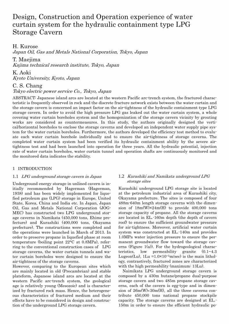
Kurashiki underground LPG storage site is located at the petroleum industrial area of Kurashiki city, Okayama prefecture. The sites is composed of four 488m-640m length storage caverns with the dimen-sion of 18m(W)×24m(H) to provide 400,000 tons storage capacity of propane. All the storage caverns are located in EL.-160m depth (the depth of cavern roof) to ensure the sufficient groundwater pressure for air-tightness. Moreover, artificial water curtain system was constructed at EL.-140m and provides 1.0MPa water injection pressure to ensure the per-manent groundwater flow toward the storage cav-erns (Figure 1(a)). For the hydrogeological charac-teristics, low permeability granite (0.1~4.3 Lugeon(Lu), 1Lu =1.0×10⁻⁵m/sec) is the main lithol-ogy, contrastively, fractured zones are characterized with the high permeability (maximum: 13Lu). Naimikata LPG underground storage cavern is composed by a 430m butane/propane dual-purpose storage cavern and two 485m propane storage cav-erns, each of the cavern is egg-type and in dimen-sion of 26m(W)30m(H), all the three caverns con-tribute 450,000 tons national propane stockpile capacity. The storage caverns are designed at EL.-150m in order to ensure the efficient hydraulic po-
Design, Construction and Operation experience of water curtain system for the hydraulic containment type LPG Storage Cavern
H. Kurose Japan Oil, Gas and Metals National Corporation, Tokyo, Japan
T. Maejima Kajima technical research institute, Tokyo, Japan
K. Aoki Kyoto University, Kyoto, Japan
C. S. Chang Tokyo electric power service Co., Tokyo, Japan ABSTRACT: Japanese island arcs are located at the western Pacific arc-trench system, the fractured charac-teristic is frequently observed in rock and the discrete fracture network exists between the water curtain and the storage cavern is concerned an impact factor on the air-tightness of the hydraulic containment type LPG storage cavern. In order to avoid the high pressure LPG gas leaked out the water curtain system, a whole covering water curtain boreholes system and the homogenization of the storage cavern vicinity by grouting works are considered as countermeasures. In this study, the authors originally designed the verti-cal/horizontal boreholes to enclose the storage caverns and developed an independent water supply pipe sys-tem for the water curtain boreholes. Furthermore, the authors developed the efficiency test method to evalu-ate each water curtain borehole individually and to ensure the air-tightness of storage caverns. The completed water curtain system had been verified its hydraulic containment ability by the severe air-tightness test and had been launched into operation for three years. All the hydraulic potential, injection rate of water curtain boreholes, water curtain tunnel and operation shafts are continuously monitored and the monitored data indicates the stability.
tential for the cavern tightness at the designed max-imum operation pressure 0.95MPa. The artificial water curtain system was constructed 25m above the storage caverns (Figure 1(b)). In Namikata site, more than 5000 hydraulic test data represents the low permeability (>0.1Lu) of the main granite for-mation. Nevertheless, relative high permeability da-ta (1Lu) has been measured at high fractured zone. Considering the heterogeneous characteristics of fractured rock mass induce the uncertainty of hy-draulic and rock mechanical behaviors, original de-signs and the observational design and construction concept were employed in the construction of the two underground LPG storage caverns.
2 ORIGINAL AIR-TIGHTNESS DESIGNS IN FRACTURED ROCK MASS
2.1 Whole covering type water curtain system
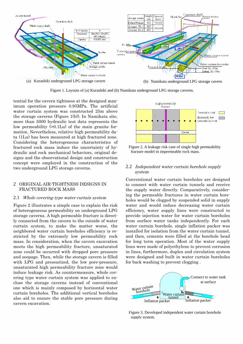
Figure 2 illustrates a simple case to explain the risk of heterogeneous permeability on underground LPG storage caverns. A high permeable fracture is direct-ly connected from the cavern to the outside of water curtain system, to make the matter worse, the neighbored water curtain boreholes efficiency is re-stricted by the extremely low permeability rock mass. In consideration, when the cavern excavation meets the high permeability fracture, unsaturated zone could be occurred with dropped pore pressure and seepage. Then, while the storage cavern is filled with LPG and pressurized, the low pore-pressure, unsaturated high permeability fracture zone would induce leakage risk. As countermeasure, whole cov-ering type water curtain system was applied to en-close the storage caverns instead of conventional one which is mainly composed by horizontal water curtain boreholes. The additional vertical boreholes also aid to ensure the stable pore pressure during cavern excavation.
2.2 Independent water curtain borehole supply system
Conventional water curtain boreholes are designed to connect with water curtain tunnels and receive the supply water directly. Comparatively, consider-ing the permeable fractures in water curtain bore-holes would be clogged by suspended solid in supply water and would induce decreasing water curtain efficiency, water supply lines were constructed to provide injection water for water curtain boreholes from surface water tanks independently. For each water curtain borehole, single inflation packer was installed for isolation from the water curtain tunnel, and then, cements were filled at the borehole head for long term operation. Most of the water supply lines were made of polyethylene to prevent corrosion in lines, furthermore, duplex and circulation system were designed and built in water curtain boreholes for back washing to prevent clogging .
Inflation packerInflation packer
Connect to water tank at surface
Water curtain tunnel
Figure 3. Developed independent water curtain borehole supply system.
Figure 1. Layouts of (a) Kurashiki and (b) Namikata underground LPG storage caverns.
(a) Kurashiki underground LPG storage cavern (b) Namikata underground LPG storage cavern
Figure 2. A leakage risk case of single high permeability fracture model in impermeable rock mass.
2.3 Cavern grouting
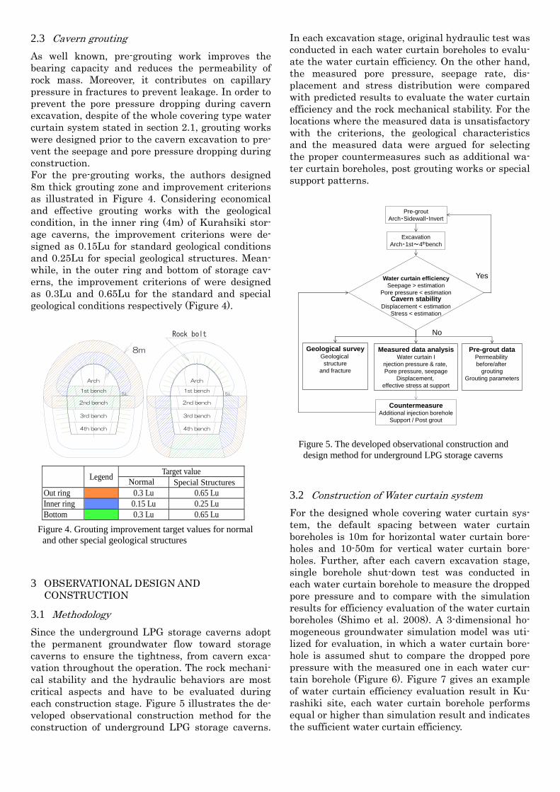
As well known, pre-grouting work improves the bearing capacity and reduces the permeability of rock mass. Moreover, it contributes on capillary pressure in fractures to prevent leakage. In order to prevent the pore pressure dropping during cavern excavation, despite of the whole covering type water curtain system stated in section 2.1, grouting works were designed prior to the cavern excavation to pre-vent the seepage and pore pressure dropping during construction. For the pre-grouting works, the authors designed 8m thick grouting zone and improvement criterions as illustrated in Figure 4. Considering economical and effective grouting works with the geological condition, in the inner ring (4m) of Kurahsiki stor-age caverns, the improvement criterions were de-signed as 0.15Lu for standard geological conditions and 0.25Lu for special geological structures. Mean-while, in the outer ring and bottom of storage cav-erns, the improvement criterions of were designed as 0.3Lu and 0.65Lu for the standard and special geological conditions respectively (Figure 4).
3 OBSERVATIONAL DESIGN AND CONSTRUCTION
3.1 Methodology
Since the underground LPG storage caverns adopt the permanent groundwater flow toward storage caverns to ensure the tightness, from cavern exca-vation throughout the operation. The rock mechani-cal stability and the hydraulic behaviors are most critical aspects and have to be evaluated during each construction stage. Figure 5 illustrates the de-veloped observational construction method for the construction of underground LPG storage caverns.
In each excavation stage, original hydraulic test was conducted in each water curtain boreholes to evalu-ate the water curtain efficiency. On the other hand, the measured pore pressure, seepage rate, dis-placement and stress distribution were compared with predicted results to evaluate the water curtain efficiency and the rock mechanical stability. For the locations where the measured data is unsatisfactory with the criterions, the geological characteristics and the measured data were argued for selecting the proper countermeasures such as additional wa-ter curtain boreholes, post grouting works or special support patterns.
3.2 Construction of Water curtain system
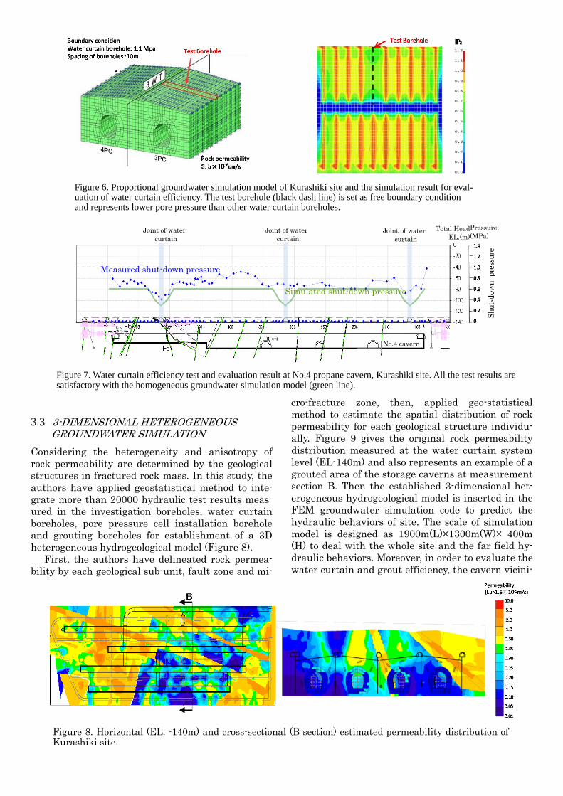
For the designed whole covering water curtain sys-tem, the default spacing between water curtain boreholes is 10m for horizontal water curtain bore-holes and 10-50m for vertical water curtain bore-holes. Further, after each cavern excavation stage, single borehole shut-down test was conducted in each water curtain borehole to measure the dropped pore pressure and to compare with the simulation results for efficiency evaluation of the water curtain boreholes (Shimo et al. 2008). A 3-dimensional ho-mogeneous groundwater simulation model was uti-lized for evaluation, in which a water curtain bore-hole is assumed shut to compare the dropped pore pressure with the measured one in each water cur-tain borehole (Figure 6). Figure 7 gives an example of water curtain efficiency evaluation result in Ku-rashiki site, each water curtain borehole performs equal or higher than simulation result and indicates the sufficient water curtain efficiency.
Arch
1st bench
2nd bench
3rd bench
4th bench
S.L.
Arch
1st bench
2nd bench
3rd bench
4th bench
S.L.
8m
Rock bolt
Legend
Target value General area Outside general area
Out ring 0.3 Lu 0.65 Lu Inner ring 0.15 Lu 0.25 Lu Bottom 0.3 Lu 0.65 Lu
Normal Special Structures
Figure 4. Grouting improvement target values for normal and other special geological structures
Pre-groutArch・Sidewall・Invert
ExcavationArch・1st~4thbench
Water curtain efficiencySeepage > estimation
Pore pressure < estimationCavern stability
Displacement < estimationStress < estimation
Geological surveyGeological structure
and fracture
Measured data analysisWater curtain I
njection pressure & rate, Pore pressure, seepage
Displacement, effective stress at support
Pre-grout dataPermeability before/after
groutingGrouting parameters
CountermeasureAdditional injection borehole
Support / Post grout
No
Yes
Figure 5. The developed observational construction and design method for underground LPG storage caverns
3.3 3-DIMENSIONAL HETEROGENEOUS GROUNDWATER SIMULATION
Considering the heterogeneity and anisotropy of rock permeability are determined by the geological structures in fractured rock mass. In this study, the authors have applied geostatistical method to inte-grate more than 20000 hydraulic test results meas-ured in the investigation boreholes, water curtain boreholes, pore pressure cell installation borehole and grouting boreholes for establishment of a 3D heterogeneous hydrogeological model (Figure 8).
First, the authors have delineated rock permea-bility by each geological sub-unit, fault zone and mi-
cro-fracture zone, then, applied geo-statistical method to estimate the spatial distribution of rock permeability for each geological structure individu-ally. Figure 9 gives the original rock permeability distribution measured at the water curtain system level (EL-140m) and also represents an example of a grouted area of the storage caverns at measurement section B. Then the established 3-dimensional het-erogeneous hydrogeological model is inserted in the FEM groundwater simulation code to predict the hydraulic behaviors of site. The scale of simulation model is designed as 1900m(L)×1300m(W)× 400m (H) to deal with the whole site and the far field hy-draulic behaviors. Moreover, in order to evaluate the water curtain and grout efficiency, the cavern vicini-
Joint of water curtain
Joint of water curtain
No.4 cavern
Shu
t-do
wn
pres
sure
Pressure(MPa)
Total HeadEL.(m)
Joint of water curtain
Measured shut-down pressure
Simulated shut-down pressure
Figure 7. Water curtain efficiency test and evaluation result at No.4 propane cavern, Kurashiki site. All the test results are satisfactory with the homogeneous groundwater simulation model (green line).
Figure 6. Proportional groundwater simulation model of Kurashiki site and the simulation result for eval-uation of water curtain efficiency. The test borehole (black dash line) is set as free boundary condition and represents lower pore pressure than other water curtain boreholes.
Figure 8. Horizontal (EL. -140m) and cross-sectional (B section) estimated permeability distribution of Kurashiki site.
ty where the mesh size was designed as 2-5m for precisely modelling the civil structures (e.g. water curtain boreholes, water curtain tunnels, access tunnel and storage caverns) and evaluating the wa-ter curtain efficiency and air-tightness.
4 HYDRAULIC BEHAVIORS EVALUATION
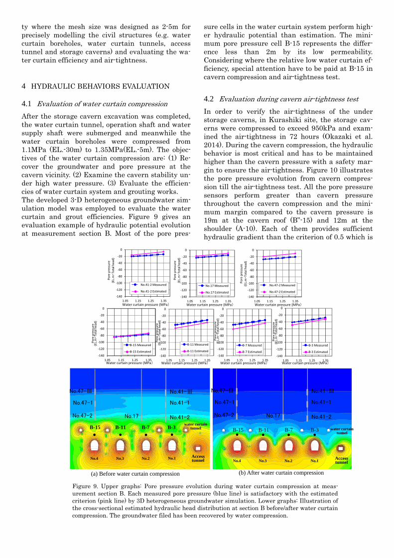
4.1 Evaluation of water curtain compression
After the storage cavern excavation was completed, the water curtain tunnel, operation shaft and water supply shaft were submerged and meanwhile the water curtain boreholes were compressed from 1.1MPa (EL.-30m) to 1.35MPa(EL.-5m). The objec-tives of the water curtain compression are: (1) Re-cover the groundwater and pore pressure at the cavern vicinity. (2) Examine the cavern stability un-der high water pressure. (3) Evaluate the efficien-cies of water curtain system and grouting works. The developed 3-D heterogeneous groundwater sim-ulation model was employed to evaluate the water curtain and grout efficiencies. Figure 9 gives an evaluation example of hydraulic potential evolution at measurement section B. Most of the pore pres-
sure cells in the water curtain system perform high-er hydraulic potential than estimation. The mini-mum pore pressure cell B-15 represents the differ-ence less than 2m by its low permeability. Considering where the relative low water curtain ef-ficiency, special attention have to be paid at B-15 in cavern compression and air-tightness test.
4.2 Evaluation during cavern air-tightness test
In order to verify the air-tightness of the under storage caverns, in Kurashiki site, the storage cav-erns were compressed to exceed 950kPa and exam-ined the air-tightness in 72 hours (Okazaki et al. 2014). During the cavern compression, the hydraulic behavior is most critical and has to be maintained higher than the cavern pressure with a safety mar-gin to ensure the air-tightness. Figure 10 illustrates the pore pressure evolution from cavern compres-sion till the air-tightness test. All the pore pressure sensors perform greater than cavern pressure throughout the cavern compression and the mini-mum margin compared to the cavern pressure is 19m at the cavern roof (B”-15) and 12m at the shoulder (A-10). Each of them provides sufficient hydraulic gradient than the criterion of 0.5 which is
Figure 9. Upper graphs: Pore pressure evolution during water curtain compression at meas-urement section B. Each measured pore pressure (blue line) is satisfactory with the estimated criterion (pink line) by 3D heterogeneous groundwater simulation. Lower graphs: Illustration of the cross-sectional estimated hydraulic head distribution at section B before/after water curtain compression. The groundwater filed has been recovered by water compression.
No.47-Ⅲ
No.47-1
No.47-2 No.17
No.41-Ⅲ
No.41-1
No.41-2
No.47-Ⅲ
No.47-1
No.47-2 No.17
No.41-Ⅲ
No.41-1
No.41-2
B-15 B-11 B-7 B-3 B-15 B-11 B-7 B-3
No.1 No.2 No.3No.4No.1No.2 No.3 No.4 Access
tunnel
water curtain tunnel
Access tunnel
water curtain tunnel
(a) Before water curtain compression (b) After water curtain compression
‐140
‐120
‐100
‐80
‐60
‐40
‐20
0
1.05 1.15 1.25 1.35
‐140
‐120
‐100
‐80
‐60
‐40
‐20
0
1.05 1.15 1.25 1.35
‐140
‐120
‐100
‐80
‐60
‐40
‐20
0
1.05 1.15 1.25 1.35
‐140
‐120
‐100
‐80
‐60
‐40
‐20
0
1.05 1.15 1.25 1.35
‐140
‐120
‐100
‐80
‐60
‐40
‐20
0
1.05 1.15 1.25 1.35‐140
‐120
‐100
‐80
‐60
‐40
‐20
0
1.05 1.15 1.25 1.35
‐140
‐120
‐100
‐80
‐60
‐40
‐20
0
1.05 1.15 1.25 1.35Water curtain pressure (MPa) Water curtain pressure (MPa) Water curtain pressure (MPa)
Water curtain pressure (MPa)Water curtain pressure (MPa)Water curtain pressure (MPa)Water curtain pressure (MPa)
Pore pressure
(EL.m
・To
tal head)
Pore pressure
(EL.m
・To
tal head)
Pore pressure
(EL.m
・To
tal head)
Pore pressure
(EL.m
・To
tal head)
Pore pressure
(EL.m
・To
tal head)
No.41‐2 Measured
No.41‐2 Estimated
No.17 Measured
No.17 Estimated
No.47‐2 Measured
No.47‐2 Estimated
B‐3 Measured
B‐3 Estimated
B‐7 Measured
B‐7 Estimated
B‐11 Measured
B‐11 Estimated
B‐15 Measured
B‐15 Estimated
Pore pressure
(EL.m
・Total head)
Pore pressure
(EL.m
・To
tal head)

determined by the administrative authority. Conse-quently, the water curtain efficiency has been vali-dated for the cavern air-tightness.
5 LONGTERM HYDRAULIC BEHAVIORS AFTER OPERATION
Both of Kurashiki and Namikata underground LPG storage cavern were launched the operation in March of 2013. In Kurashiki, the water injection pressure is maintained as EL.-3m and EL.2m at water curtain tunnel and water curtain boreholes respectively. Regarding to the long term hydraulic behaviors, the water injection rate of water curtain tunnel/ borehole, seepage rate, groundwater level, pore pressure in the cavern vicinity are always mon-itored for management and maintenance. As the monitoring results, generally, the long term groundwater level and pore pressure is stable and the air-tightness is ensured. The seepage of storage caverns is generally stable but slightly decreasing trend, in consideration, probably the cavern vicinity is clogged by suspended solid in groundwater. Con-sequently, the water injection rate of water curtain system also represent stable but slightly decreasing trend.
6 CONCLUSION
Kurashiki underground LPG storage site applies water curtain system to ensure the cavern air-tightness by maintaining the sufficient hydraulic potential from the construction phase throughout the operation. For the purpose, the authors have de-signed the horizontal/vertical water curtain bore-holes to enclose the storage cavern and to injection high pressure water prior to the cavern excavation.
During the cavern excavation, the authors have conducted the hydraulic test in water curtain bore-holes to evaluate the efficiency. The authors also have established a high accuracy 3-dimensional groundwater simulation model and utilized it to evaluate the hydraulic behaviors. For the low water curtain efficiency zone, the authors designed the additional boreholes and post grouting works as countermeasures.
Throughout the cavern compression to the cavern air-tightness test, all pressure sensors perform high hydraulic gradient throughout the cavern compres-sion and satisfactory with the criterion of 0.5. The test result has validated the performance of con-structed water curtain system, also verified the ap-plicability of our observational water curtain system construction method. After the operations was launched in Mars, 2013, all the hydraulic potential, injection rate of water curtain boreholes, water cur-tain tunnel and operation shafts are continuously monitored and the monitored data indicates the stability.
REFERENCE
Hagerman T. & Morfeldt C.O. (1955), Air-tight and wa-ter-tight rock chamber, Civil Engineering and Pub-lic Works Review, Feb. 1955.
Shimo M., Mashimo M., Maejima T., Yamamoto H. & Aoki., K. 2008. Hydraulic testing using injection borehole array for groundwater management dur-ing construction of LPG storage cavern. Proceed-ings of the 37th Symposium on Rock Mechanics: 55-60.
Okazaki Y., Kurose, H., Okubo, S., Maejima, T. & Aoki. K. 2014, Cavern gas-tightness test and Groundwa-ter management for the underground rock cavern at NAMIKATA national LPG stockpiling base. Pro-ceedings of the 8th Asian Rock Mechanics Symposi-um: 2261-2271
-180-170-160-150-140-130-120-110-100-90-80-70-60-50-40-30-20-10
0
5/1 5/6 5/11 5/16 5/21 5/26 5/31 6/5 6/10
Po
re p
ress
ure
(E
L.m
・T
ota
l hea
d)
Figure 10. Comparison of pore pressure evolution with cavern pressure (converted to hydraulic head at cavern shoulder EL.-165m). Throughout the cavern pressurization stage, stabilization stage and air-tightness stages, even the most critical pore pressure sensor A-10 also indi-cates the sufficient hydraulic head by 12m higher than the cavern pressure.
Water curtain pressure (EL.-15m)
Cavern pressurization stage Stabilization Air-tightnesstest
Cavern Pressure
(Converted to total head
at cavern shoulder depth EL.-165m) A-10
A-10( EL.-53m)
Cavern (EL.-65m)
12m