design, construction and testing of pumps 2013 - türk … · 2/11 design, construction and testing...
TRANSCRIPT
DESIGN, CONSTRUCTION AND TESTING OF PUMPS
2013
This latest edition incorporates all rule changes. The latest revisions are shown with a vertical line. The section title is framed if the section is revised completely. Changes after the publication of the rule are written in red colour. Unless otherwise specified, these Rules apply to ships for which the date of contract for construction as defined in IACS PR No.29 is on or after 4th of February 20. "General Terms and Conditions" of the respective latest edition will be applicable (see Rules for Classification and Surveys). If there is a difference between the rules in English and in Turkish, the rule in English is to be considered as valid. This publication is available in print and electronic pdf version. Once downloaded, this document will become UNCONTROLLED. Please check www.turkloydu.org for the amended and valid version. All rights are reserved by Türk Loydu, and content may not be reproduced, disseminated, published, or transferred in any form or by any means, except with the prior written permission of TL.

TÜRK LOYDU
Head Office Postane Mah. Tersaneler Cad. No:26 Tuzla 34944 İSTANBUL / TÜRKİYE
Tel : (90-216) 581 37 00
Fax : (90-216) 581 38 00
E-mail : [email protected]
http://www.turkloydu.org
Regional Offices
Ankara Eskişehir Yolu Mustafa Kemal Mah. 2159. Sokak No : 6/4 Çankaya - ANKARA / TÜRKİYE
Tel : (90-312) 219 56 34 - 219 68 25
Fax : (90-312) 219 69 72
E-mail : [email protected]
İzmir Atatürk Cad. No :378 K.4 D.402 Kavalalılar Apt. 35220 Alsancak - İZMİR / TÜRKİYE
Tel : (90-232) 464 29 88
Fax : (90-232) 464 87 51
E-mail : [email protected]
Adana Çınarlı Mah. Atatürk Cad. Aziz Naci İş Merkezi No:5 K.1 D.2 Seyhan - ADANA / TÜRKİYE
Tel : (90- 322) 363 30 12
Fax : (90- 322) 363 30 19
E-mail : [email protected]
Marmaris Atatürk Cad. 99 Sok. No:1 Ketenbaş Apt. Kat:4 Daire 6 Marmaris - MUĞLA / TÜRKİYE
Tel : (90- 252) 412 46 55
Fax : (90- 252) 412 46 54
E-mail : [email protected]
List of Rules
Part Chapter Title A 1 Rules for Classification of Steel Ships – Hull A 2 Rules for Classification of Steel Ships – Material A 3 Rules for Classification of Steel Ships – Welding B 4 Rules for Classification of Steel Ships – Machinery B 5 Rules for Classification of Steel Ships – Electrical Installation C 7 High Speed Crafts C 8 Chemical Tankers C 9 Construction and Classification of Yachts C 10 Liquefied Gas Tankers C 11 Fire Fighting Ships C 12 Oil Recovery Vessels C 13 Escort Tugs C 14 Fishing Vessels C 15 Refrigerating Installations C 16 Pipe Laying Vessels C 17 Pusher, Pusher/Barge Units C 18 Drilling Vessels C 19 Inland Waterway Vessels C 20 Cable Laying Vessels C 21 Navigation Bridge Visibility, Bridge Arrangement and Equipment Rules C 22 Dynamic Positioning Systems C 23 Redundant Propulsion and Steering Systems C 24 Chemical Recovery Vessels C 25 Machinery Condition Monitoring C 26 Use of Fuel Cell Systems on Board of Ships and Boats C 27 Construction of Wooden Passenger Vessels Less than 24 m. in Length C 28 Ventilation C 30 Wooden Fishing Vessels C 32 Rigging for Large Sailing Ships C 33 Construction of Polar Class Ships D 50 Regulation for Lifting Appliances D 51 Stowage and Lashing of Containers D 52 Diving Systems D 53 Submersibles D 54 Underwater Equipment D 55 Construction, Repair and Testing of Freight Containers D 58 Ocean Towage D 59 Offshore Technology - Classification, Certification and Surveys D 60 Offshore Technology - Mobile Offshore Units D 61 Offshore Technology - Fixed Offshore Installations D 62 Offshore Technology - Structural Design D 63 Offshore Technology Machinery Installations D 64 Offshore Technology – Electrical Installations D 70 Multiple Point Mooring Systems D 76 Environmental Service System D 77 Certification of Floating Oil Booms E 101 Naval Ship Technology, Classification and Surveys E 102 Naval Ship Technology, Hull Structures and Ship Equipment E 103 Metallic Materials, Special Materials for Naval Ships E 104 Naval Ship Technology, Propulsion Plants E 105 Naval Ship Technology, Electrical Installations E 106 Naval Ship Technology, Automation E 107 Naval Ship Technology, Ship Operation Installations and Auxiliary Systems E 111 Naval Ship Technology, Submarines E 112 Naval Ship Technology, Remotely Operated Underwater Vehicles E 113 Naval Ship Technology, Air Independent Power Systems for Underwater Use F 200 Certification of Wind Turbines F 201 Certification of Offshore Wind Turbines F 202 Certification of Condition Monitoring Systems for Wind Turbines
A, B Design, Construction and Testing of Pumps 1/11
TÜRK LOYDU – 2012
DESIGN, CONSTRUCTION AND TESTING OF PUMPS
Page
A. General ................................................................................................................................................................... 1
B. Design and Construction Principles ....................................................................................................................... 1
C. Testing .................................................................................................................................................................... 3
Annex A Illustration Of Principles Of Pumps
A. General
1. Scope
The following Rules apply to the design, construction and
testing of pumps for the handling of liquids.
The application of these Rules covers pumps whose
capacity in accordance with the TL Rules, Chapter 4 –
Machinery, Section 16, D. have to be verified in the
manufacturer's works as well as pumps and motors of
hydraulically operated systems in accordance with
Chapter 4 – Machinery, Section 10.
These Rules may be similarly applied to other
pumps as appropriate.
2. Definition
For the purpose of these Rules, liquid pumps include:
- Rotodynamic pumps
- Side channel pumps
- Rotary and oscillating positive displacement
pumps
- Liquid ejectors For pumps of other designs, the requirements are to be
agreed on a case to case basis.
3. Documents to be Submitted
In the case of pumps for handling liquid gases,
dangerous chemicals and liquid foodstuffs, sectional
drawings together with details relating to the proposed
materials and operating conditions are to be submitted in
triplicate to the TL Head Office for approval.
Approval of drawings is not normally required for other
pumps.
In individual cases and depending on the design and
application the Society does, however, reserve the right
to call for the documentation necessary to an assessment
of the pump in question.
B. Design and Construction Principles
1. Materials
1.1 Approved materials
The materials of the pump components shall be suitable
for the proposed applications. They are to be selected
with due regard to the operating conditions and the
nature of the liquid to be handled. The Rules for Materials
issued by TL are to be observed. These Rules apply
analogously to pressurized parts attached to the pumps.
Where the working temperature (tper) of the liquid to be
pumped is ≤ –10 °C, the choice of materials is subject to
the requirements of TL Rules, Chapter 2 –Materials.
Where dangerous chemicals are to be pumped, evidence
is to be supplied to TL attesting the suitability of the
materials used.

2/11 Design, Construction and Testing of Pumps B
TÜRK LOYDU – 2012
1.2 Requirements on material manufacturers
Casings for pumps intended to be used for piping
systems of pipe class (See Chapter 4- Machinery,
Section 16, Table 16.1) I and II shall be manufactured by
TL approved manufacturers. For the use in pipe class III
piping systems an approval according to other
recognized standards may be accepted.
1.3 Limits on the application of materials for
pump casings
1.3.1 Cast iron with lamellar graphite (at least EN-
GJL-200)
max. allowable working temperature tper ≤ 200 °C
max. allowable working pressure Pe,per ≤ 16 bar
Limitations:
- For boiler water Pe,per ≤ 10 bar
- For liquid fuels, lubricating oil, tper ≤ 60 °C
and for flammable hydraulic Pe,per ≤ 7 bar fluid
Not permitted:
- For casings of circulating pumps for heat-
transfer oil
- For casings of pumps for handling of dangerous
chemicals
1.3.2 Nodular cast iron (Elongation A5 at least 12
%)
max. allowable working temperature tper ≤ 300 °C for
nodular cast iron in normal quality
max. allowable working temperature tper ≤ 350 °C for
nodular cast iron in special quality according to TL Rules
Chapter 2 – Materials, Section 7, acceptable for casings
of circulating pumps for heat-transfer oil
1.3.3 Steel and cast steel for general applications
max. allowable working temperature tper ≤ 300 °C
1.3.4 Cast copper alloys
max. allowable working temperature tper ≤ 200 °C for
copper and aluminium brass,
max. allowable working temperature tper ≤ 300 °C for
copper nickel alloys
1.3.5 Aluminium casting alloys
max. allowable working temperature tper ≤ 200 °C with
the approval of the TL.
1.3.6 Plastics
The use of plastics requires the approval of TL in the
individual case of application.
1.4 Casing repairs
Casting defects in pump casings may be repaired only
by recognized methods. The TL surveyor is to be
notified prior to the execution of the repair.
2. Protection Against Excessive Pressure
2.1 Rotodynamic pumps must be so designed that
they can be operated for a short time without damage
even with the discharge line closed.
2.2 Positive displacement pumps must be protected
against excessive pressure increases in the pump casing
by fitting relief valves which cannot be adjusted to the
closed position.
2.3 Pumps which do not clearly conform to one of
these two designs must comply with requirement 2.1 or
2.2.
3. Rated Output of Prime Mover
3.1 General requirements
The rated output of the prime mover is to be determined
in such a way as to ensure the reliable operation of the
pump under all anticipated operating conditions.
It is required to be compatible with the mode of operation,
the characteristic curve of the pump and with the
properties of the liquid to be pumped.
3.2 Prime movers for rotodynamic pumps
By the way of a guide, the following values can, for
example, normally be regarded as adequate in the case
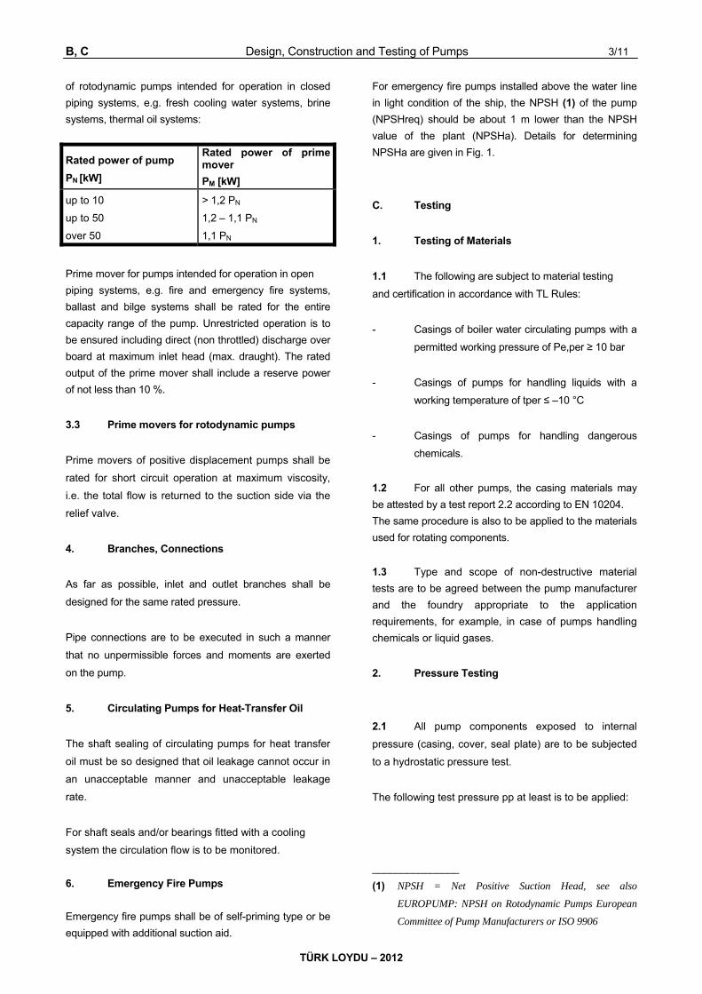
B, C Design, Construction and Testing of Pumps 3/11
TÜRK LOYDU – 2012
of rotodynamic pumps intended for operation in closed
piping systems, e.g. fresh cooling water systems, brine
systems, thermal oil systems:
Rated power of pump
PN [kW]
Rated power of prime mover
PM [kW]
up to 10
up to 50
over 50
> 1,2 PN
1,2 – 1,1 PN
1,1 PN
Prime mover for pumps intended for operation in open
piping systems, e.g. fire and emergency fire systems,
ballast and bilge systems shall be rated for the entire
capacity range of the pump. Unrestricted operation is to
be ensured including direct (non throttled) discharge over
board at maximum inlet head (max. draught). The rated
output of the prime mover shall include a reserve power
of not less than 10 %.
3.3 Prime movers for rotodynamic pumps
Prime movers of positive displacement pumps shall be
rated for short circuit operation at maximum viscosity,
i.e. the total flow is returned to the suction side via the
relief valve.
4. Branches, Connections
As far as possible, inlet and outlet branches shall be
designed for the same rated pressure.
Pipe connections are to be executed in such a manner
that no unpermissible forces and moments are exerted
on the pump.
5. Circulating Pumps for Heat-Transfer Oil
The shaft sealing of circulating pumps for heat transfer
oil must be so designed that oil leakage cannot occur in
an unacceptable manner and unacceptable leakage
rate.
For shaft seals and/or bearings fitted with a cooling
system the circulation flow is to be monitored.
6. Emergency Fire Pumps
Emergency fire pumps shall be of self-priming type or be
equipped with additional suction aid.
For emergency fire pumps installed above the water line
in light condition of the ship, the NPSH (1) of the pump
(NPSHreq) should be about 1 m lower than the NPSH
value of the plant (NPSHa). Details for determining
NPSHa are given in Fig. 1.
C. Testing
1. Testing of Materials
1.1 The following are subject to material testing
and certification in accordance with TL Rules:
- Casings of boiler water circulating pumps with a
permitted working pressure of Pe,per ≥ 10 bar
- Casings of pumps for handling liquids with a
working temperature of tper ≤ –10 °C
- Casings of pumps for handling dangerous
chemicals.
1.2 For all other pumps, the casing materials may
be attested by a test report 2.2 according to EN 10204.
The same procedure is also to be applied to the materials
used for rotating components.
1.3 Type and scope of non-destructive material
tests are to be agreed between the pump manufacturer
and the foundry appropriate to the application
requirements, for example, in case of pumps handling
chemicals or liquid gases.
2. Pressure Testing
2.1 All pump components exposed to internal
pressure (casing, cover, seal plate) are to be subjected
to a hydrostatic pressure test.
The following test pressure pp at least is to be applied:
_______________
(1) NPSH = Net Positive Suction Head, see also
EUROPUMP: NPSH on Rotodynamic Pumps European
Committee of Pump Manufacturers or ISO 9906

4/11 Design, Construction and Testing of Pumps Annex A
TÜRK LOYDU – 2012
Fig. 1 Calculation of NPSHa for emergency fire pumps which are installed above the water line in light
condition
Pp = 1,5 Pe,per where Pe,per ≤ 200 bar subject to a
minimum of Pp = 4 bar
Pp = Pe,per + 100 bar where Pe,per > 200 bar
Pe,per = maximum allowable working pressure
2.1.1 In the case of rotodynamic pumps, the
maximum allowable working pressure Pe,per is equal to
the sum of the pressure in the suction branch and the
maximum pressure difference according to the pump
characteristic.
2.1.2 In case of positive displacement pumps, the
maximum allowable working pressure Pe,per is equal
to the pressure which occurs on the discharge side
when the total flow is returned to the suction side via the
relief valve. The maximum pressure at the suction
branch shall be considered.
C Design, Construction and Testing of Pumps 5/11
TÜRK LOYDU – 2012
2.2 For the purpose of hydrostatic pressure testing,
pump casings shall not be painted on their internal
or external surfaces.
3. Performance Testing
3.1 The following pumps are subject to final
inspection and to hydraulic performance testing in the
manufacturer's works under the supervision of a TL
Surveyor:
- Bilge pumps / bilge ejectors
- Ballast pumps
- Seawater cooling pumps
- Fresh water cooling pumps
- Cooling pumps for fuel injection valves
- Fire pumps
- Emergency fire pumps
- Condensate pumps
- Boiler feed water pumps
- Boiler water circulating pumps
- Lubricating oil pumps
- Fuel oil booster and transfer pumps
- Circulating pumps for heat-transfer oil
- Brine pumps
- Refrigerant circulating pumps
- Cargo pumps
- Hydraulic pumps for controllable pitch propellers
Other hydraulic pumps / hydraulic motors, see TL Rules
Chapter 4 - Machinery, Section 10.
3.2 The following contractually agreed operating
data are to be verified during the performance test:
Volume rate of flow (2) Q [m3/h]
Delivery head H [m]
Pump power input P [kW]
Speed of rotation n [min-1]
3.3 As a standard procedure the hydraulic
performance test shall be performed on manufacturer's
test bench.
The procedure followed shall be based on recognized
national or international Standards and Regulations,
such as:
- DIN EN ISO 9906 – Rotodynamic pumps –
Hydraulic performance acceptance test grade
2,
- VDMA 24 284 – Testing of positive
displacement pumps – General regulations for
testing.
If the contract provides for a performance test in
accordance with one of the aforementioned standards
or a comparable regulation the pump manufacturer is
bound to hold the said standard available for
consultation during the performance test.
3.4 If the performance test is conducted without
the corresponding prime mover but with a test bench
motor, deviations from the nominal speed of rotation nN
may result which can be tolerated within specific limits.
In case of rotodynamic pumps, the speed of rotation
during testing shall be in line with ISO 9906.
Accordingly, the speed of rotation during testing shall be
within the range 50 % and 120 % of the specified
speed.
––––––––––––––
(2) The volume rate of flow is defined as the usable
volume rate which is delivered by the pump through its
outlet cross-section (pressure socket).

6/11 Design, Construction and Testing of Pumps Annex A
TÜRK LOYDU – 2012
In order to translate the performance data Q, H and P
measured at test speed n to the corresponding values
for the specified speed nN, the following equations may
be applied:
3
NN
2
NN
NN
n
nPP
n
nHH
n
nQQ
3.5 For positive displacement pumps, the
permissible deviations call for special agreement
depending on the design involved.
3.6 Conversion of the measured power input P to
the nominal power input PN is also required where the
power input is measured with a liquid which differs as
regards density and/or viscosity from the liquid specified
in the contract (3)
3.7 Where the contract calls for verification of the
NPSH value, an approximation formula is to be agreed
between customer and supplier to enable the
conversion to be made if the test speed differs from the
nominal speed.
3.8 Where pumps subject to mandatory testing are
hydraulically driven, the corresponding hydraulic motors
and hydraulic pumps are to undergo a performance test,
unless the pump is performance-tested in conjunction
with the entire unit.
4. Other Tests
4.1 On positive displacement pumps the setting
and correct dimensioning of the relief valve is to be
checked. Generally, the set pressure, the opening
pressure and the reseating pressure shall be measured
and documented. Where a positive displacement pump
is supplied without a relief valve, this point is to be noted
in the Test Certificate.
––––––––––––––
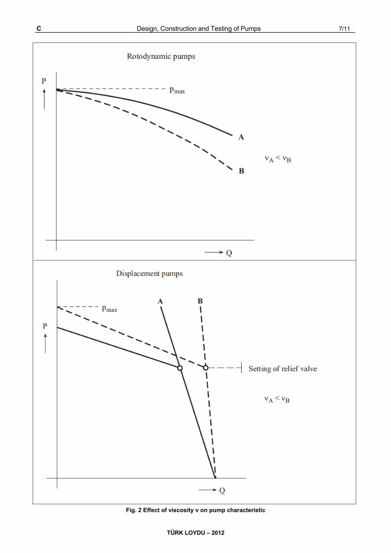
(3) The effect of viscosity on the characteristic of pumps is
shown in Figure 2.
4.2 With self-priming rotodynamic pumps as well
as for rotodynamic pumps with attached or built in
suction aid, the functioning of the air intake stage is to
be included within the scope of performance test.
4.3 During the performance test, the pump is to be
checked for smooth running (4) and bearing
temperature.
4.4 Where the performance test is carried out on
the entire unit comprising the pump, coupling, prime
mover and common base plate, the alignment of the
unit is to be checked. The fact that the test has been
performed on the entire unit is to be noted in the Test
Certificate.
4.5 In case of performance testing of bilge ejectors
the pressures shall be within ± 3 % of the nominal data.
The resulting flow at the suction side may not deviate by
more than –5 %. Higher volume rate of flows are
permitted.
5. Test Documents
5.1 The documents required for the various tests
shall be supplied by the pump manufacturer to the
Surveyor in good time and at the latest at the time of
carrying out the tests.
5.2 A TL Test Certificate is to be issued showing
the results of the tests. Where the extent of the tests
goes beyond that specified by TL, the TL Test
Certificate may be supplemented by the pump
manufacturer's own test report.
––––––––––––––
(4) The assessment may be based on VDI Regulation 2056
"Criteria for the assessment of mechanical vibration in
machines" or on a comparable standard.
C Design, Construction and Testing of Pumps 7/11
TÜRK LOYDU – 2012
Fig. 2 Effect of viscosity ν on pump characteristic
8/11 Design, Construction and Testing of Pumps Annex A
TÜRK LOYDU – 2012
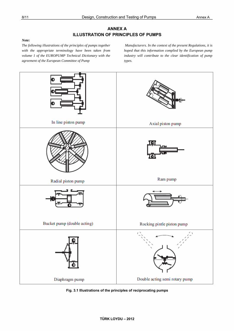
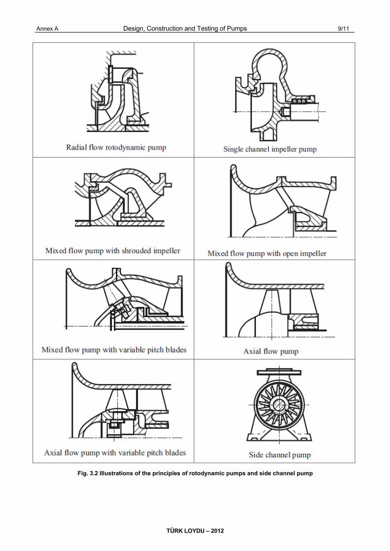
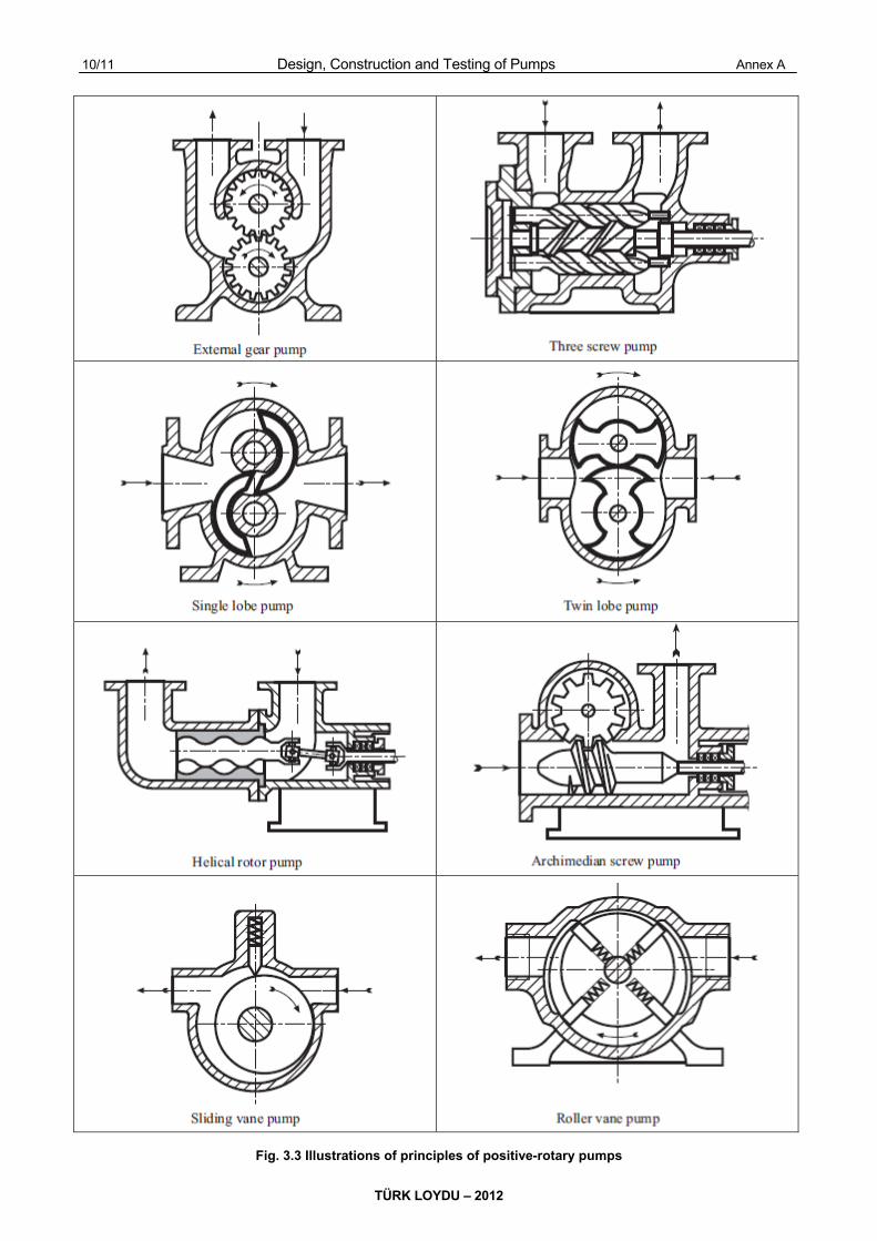
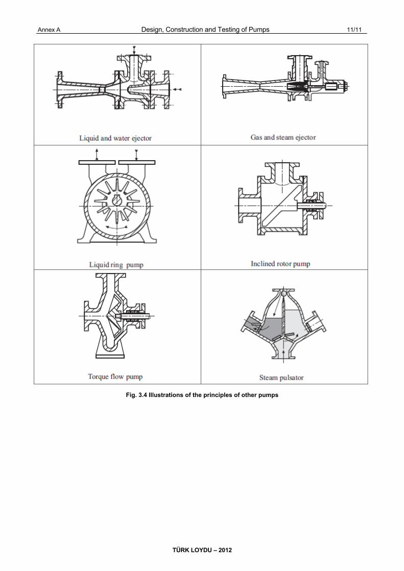
ANNEX A ILLUSTRATION OF PRINCIPLES OF PUMPS
Note:
The following illustrations of the principles of pumps together
with the appropriate terminology have been taken from
volume 1 of the EUROPUMP Technical Dictionary with the
agreement of the European Committee of Pump
Manufacturers. In the context of the present Regulations, it is
hoped that this information complied by the European pump
industry will contribute to the clear identification of pump
types.
Fig. 3.1 Illustrations of the principles of reciprocating pumps
Annex A Design, Construction and Testing of Pumps 9/11
TÜRK LOYDU – 2012
Fig. 3.2 Illustrations of the principles of rotodynamic pumps and side channel pump
10/11 Design, Construction and Testing of Pumps Annex A
TÜRK LOYDU – 2012
Fig. 3.3 Illustrations of principles of positive-rotary pumps
Annex A Design, Construction and Testing of Pumps 11/11
TÜRK LOYDU – 2012
Fig. 3.4 Illustrations of the principles of other pumps