design criteria for the high- and intermediate-level
TRANSCRIPT

II'
,
OR.Nl... . -.~I1.-.'·'lt1
'~,JlIOet'f(~~ ~i~L \1lnriJ.i¢" !~~ operated by
UNION CARBIDE CORPORATION for the
U.S. ATOMIC ENERGY COMMISSION
ORNL TM- 211
COpy NO. - (
• DATE - April 27, 1962
DESIGN CRITERIA FOR '!HE HIGH- AND INTERMEDIATE-LEVEL LIQUID WASTE FACILITY
F. E. Harrington and H. O. Weeren
ABSTRACT
Presented herein are the Design Criteria for the Highand Intermediate-Level Liquid Waste Facility to be constructed at ORNL.
NOTICE
This document contains information of a preliminary nature and was prepared primarily for internal use at the Oak Ridge National Laboratory, It is subiect to revision or correction and therefore does not represent a final report. The information is not to be abstracted, repri nted or otherwi se gi ven publ ic: di ssemination without the approval of the ORNL patent branch, Legal and information Control Department.

..
-2-
COlJTEN'rS
LO Introduction
2.0 General Description of Facility
2.1 Brief Description of Process and Equipment
2.2 Brief Description of Location and structure
3.0 Architectural and Structural
3.1 Personnel Access and Containment Zones
3.2 Structural Req~irements
~-.O Ventilation System
5.0 Equipment
6.0
'( .0
5.1 Hajor Process Equipment
5.2 VOG Equipment
5.3 Other Equipment
Piping
6.1 Genera.l
6.2 Process Piping
6.3 Miscellaneous
Electrica.l
7.1 General
7.2 Lighting and Wall Receptacle Requirements
'( .3 vlelding Receptacles
7 .1~ Special System
0.0 Instrumentation
Appendix A
Appendix B
Appendix C
Appendix D
Appendix E
3
3 1:-
5 6
6
7
9
9 10
11
11
12
12
12
13
15
15
15
16 16
17
18
34
35 l~2
53

•
1.0 INTRODUCTION
T~e purpose of this memo is to present sufficient data to initiate
immediately the necessary Cost Estimate, Preliminary Proposal, and Title I
Engineering for the IIHigh- and Intermediate-Level Waste Facility."
The over-all modifications and additions to the ORNL aqueous waste
system include:
1. The construction of two new 50,000-gallon water-cooled high-activity
level waste storage tanks and a l5,OOO-gallon per day evaporator for
intermediate and high level waste;
2. T~e addition of a waste collection facility to serve all existing and
proposed facilities in Melton Valley and tie-in of same to the Bethel
Valley system;
3. The installation of a facility to guarantee that all low-level process
waste is reduced in activity to levels recommended for discharge to
populations in the vicinity of atomic energy installations.
This report covers the first of these items. A separate report for
Item 2 has been issued as CF-6l-5-24. Item 3 will be delayed about one
year pending the construction and operation of test plants to further
evaluate both the ion exchange and vermiculite absorption methods of process
water cleanup.
A more complete summa.ry of the studies leading up to criteria given in
this memo, and on the drawings referred to herein, is presented in CF-6l-5-22,
"A study of Modifications for ORNL Liquid Waste System," by H. O. Weeren,
J. O. Blomeke, and W. G. stockdale.
Current plans are for the ORNL Engineering Department to submit the
Preliminary Proposal to the Atomic Energy Commission on July 1 of this year.
Upon approval of this "Proposal" the Engineering Department will proceed with
Title II Engineering.
As in other projects the latest revisions of AEC Criteria, Southern
Standard Building Code, ACI Standards, AISC Specifications and NFPA Exit
Code applies •
2.0 GENERAL DESCRIPTION OF FACILITY
The proposed High- and Intermediate-Level Liquid Waste Facility will in
clude two 50,000-gallon water-cooled stainless steel waste storage tanks for
permanently storing high activity-level waste and a l5,000-gallon/day

•
•
-4-
evaporator for routinely concentrating neutralized intermediate-level waste
and occasionally concentrating high-level waste. The relationship between
the facility and the total plant liquid ~~ste system is shown on Dwg. C-34529.
Tne shaded boxes represent this new facility.
The line of demarkation between intermediate- and high-level waste has
been set at 10 curies/gallon, which corresponds to ~.l Btu/hr'gal. This
value was chosen because it was thought to be the maximum activity which
can be safely stored in the six existing 170,OOO-gallon concrete waste storage
tanks. It has been calculated that these tanks, which are uncooled, can only
dissipate about 17,000 Btu/hr through the surrounding earth from boiling
solutions.
2.1 Brief Description of Process and E~uipment
At the present time there are no facilities at ORNL for the permanent
storage of high-level aqueous wastes (> 10 curies/gallon). Admittedly, small
to moderate quantities of neutralized higher level wastes can be stored in
the existing concrete tanks if they can be diluted by the present tank con
tents to < 10 curies/gallon. The proposed 50,000-gallon tanks will be capable
of storing acid waste with activities up to 2800 curies/gallon which will
generate about 32 Btu/hr'gal if produced from 6-months' cooled high-burnup
uranium. This is based on the filling of the tank in 2-1/2 years and
represents a daily average input of 55 gallons. A second tank is provided as
a standby to receive the contents of the first tank in case of leakage. Each
tank will have a cooling capacity of 400,000 Btu/hr; 320,000 Btu/hr capacity
in the form of external cooling pipes and 80,000 Btu/hr capacity in internal
coils. Both tanks will be served by a common reflux condenser with a capacity
of ~·50,000 Btu/hr to provide cooling in the event of a cooling coil failure.
Tne remainder of the off-gas system is shared in common with the evaporator
and its auxiliaries.
The proposed 15,000-gallon/day intermediate-level evaporator will be
capable of evaporating high-level wastes to an activity level of 2800
curies/gal (at 6 months' cooling), but will be used primarily for the
volume reduction of supernatants from the present concrete intermediate-level
waste tanks. These supernatants will no longer be routed to the seepage pits
in Melton Valley. This stream has an average composition of 0.3 ~ NaN03--
0.2 M NaOH and an average activity of 10 millicuries/gallon. The design is
based on a 10:1 concentration factor for waste of this composition. The
•
•
' •• as"(;e will be pumped and/or jetted batch-wise from existing \'/B,ste facilities
GO a new evaporator feed tank. The evaporator will have a steam coil to serve
as a :;:'oao breaker and an impingement baffle incorporated internally. The
OVel'llead from the evaporator will be filtered in a Yorkmesh filter similar
to t:le unit described in BNL-121 and then will be condensed in a stainless
steel condenser serviced by recirculated cooling water. Tne condensate,
nOl~nally containing < 10 microcuries/gallon of activity, will be sent to the
e:::dstinc equalization basin. :rf it contains higher activity levels, it will
be returned either to the evaporator for reprocessing or to W-5 for storage.
Noncona.ensables will be scrubbed with caustic solution, heated, and then
filtered before being dishcarged through a 6-in. VOG line connecting to
the 3039 VOG system near Bldg. 3505. The VOG system is shown schematically
on D-SK-Jl. ~le evaporator concentrates will be returned to the concrete
tanks if ::: 10 curies/gallon.
Iilaterial, heat, and activity balances for the system are shown in
Dwg. E-34607. Engineering flowsheets are shown in D-34530, D-34549 through
D- 3l~ 552, and D- 34621-
2.2 Brief Description of Location and Structure
~he proposed facilities will be located in the excavation made for the
abrOGated 2527 building as shown on E-34618. The decision to use this site
~~s b~sed on its proximity to the present waste facilities and the savings
which accrue by use of an existing excavation, much of which already has
poured concrete foundation pads. Existing concrete elevations will be used
as much as possible with a proposed layout shown on E-34525.
'1.'1"1e fadli ty will contain three process cells with the following inside
dimensions:
Evaporator Cell - Cell I 14 x 26 x 20 ft deep
Condenser Cell - Cell II 14 x 8 x 12 ft deep
VOG Cell - Cell III 14 x 8 x 11-1/2 ft deep
These cells, the combination valve and pipe tlmnel, and the ventilation
filter pit constitute the primary containment zone. Containment criteria
will conform to present plant standards for high-level beta-gamma contain
ment. The valves necessary for alternate routing of waste streams is shown
on C-34260. TI~e ventilation exhaust filter pit will be external to the
building since the secondary containment is part of the filter changing
apparatus.

•
..
-6-
'me secondary containment zone--all the building exclusive of the cells-
consists of:
1. A change room and operating area, 16 x 55 x 14 ft high south of the
building;
2. A crane bay, 18 ft high, over the removable roof slabs for cells I, II,
and III serviced by a 2O-ton gantry crane;
3. A sample gallery service area, 12 x 25 x 9, on the north side over a
portion of the high-level cell.
~1e crane bay will have a telescoping truck door at the west end and
will have tracks for the crane extending 20 ft outside the building. A
finned water-to-air heat exchanger, LR-DWG-57135, will be located south of
the building.
3.0 ARCHITECTURAL AND STRUCTURAL
Personnel Access and Containment Zones
Area
High-Level Tank Annulus
Cell I
Cell II, II, Pipe Tunnel
Sample Room
Crane Area
Operating Area
Change Room
Personnel Access
No normal access
No normal access
Very limited
Limited
Limited
Unlimited
Unlimited
Containment
Primary
Primary
Primary
Secondary
Secondary
Secondary
Secondary
Zone
p~ emergency access hatch, covered by the Sample Room, is provided to
each storage tank for entrance. Cell I will be entered only after extensive
decontamination. Access to Cells I, II, and III is by means of removable
roof plugs. These plugs should be sized so that the largest equipment item
in each cell can be replaced.
Current thinking indicates the personnel in the facility at anyone
time will be:
Shift Normal Maximum
4-12 1 2 12-8 1 2 8-4 2 .-2..
Total 4 Tota.l 9

•
•
•
-7-
The change room will be divided into a locker section and a cleanup
section. All normal access to the facility must pass through both sections.
A pcrsonnE:!l monitorinG station ,rill be located where one leaves the cleanup
station to enter the locker section. In the locker section, lockers for 5
men, clean protective clothing bins, and a clean towel bin will be provided.
70ilet facilities, showers, and soiled laundry bins will be in the cleanup
section.
The operating area will contain the instrument penal. Greater than 90% of all norma.l operations will be controlled from this area. The instrument
details presented on the engineering flowsheets will be used by the Instrument
Departr,1ent to obtain, first, the necessary data for the cost estimate and then
for detail design such as the panelboard layout. The instrument estimate will
not include the piping runs from the panel to individual equipment items. Certain
critical readings will be telemetered to a central monitoring station to be built
north of Building 3026. The cost estimate should include this telemetering
cost item as a separate unit until a firm decision on how this operation is
to be charged. ~le pOints telemetered are listed, using engineering flowsheet
nomenclature, in the Appendix.
'l'he Crane Area and the Sampling Room over the High-Level Storage Cell
,viII be limited access areas. These areas will contain the equipment which
could conceivably allow some activity to breech the cells, i.e., samplers
and piping tie-ins to the cells. Cold equipment may also be located in these
areas, i.e., the two cold makeup tanks I-a and M3 and service headers. A
possible sampling method is shovm on D-34276. This concept is a modification
of the 'rhorex sal1l]?line; system. The transfer station indicated is a necessary
addition since silielded carriers will have to convey the samples to the
j\.nalytical Laboratory.
3.2 Structural Requirements
7he cell block structure shown on E-34525 provides the radiation shield
necessary to insure safe working conditions in the secondary containment
zone. The shielding calculations are shown in the Appendix of CF-61-5-22.
The wall thicknesses indicated on the drawing are for normal concrete.
This structure should be capable of withstanding 900 lbs/sq ft of shock
pressure. The removable roof plugs will be supported by the cell structure.
The floor loading for the various areas in the secondar"'J containment
zone pose no problem. Cart movement of a 2500-lb security file is the most

(',
-0-
severe usage for the change room, operating area, and sample room. n1e floor
loading of the crane area is set by the cell blocl~ structure requirements
plus the gantry crane.
The potential of an area to become contaminated should be reflected in
the design of the various surfaces encountered in the building. Every effort
shall be made to minimize all forms of cracks and crevices and porous surfaces.
Each individual area shall be designed as air-tight as possible to confine
contamination in the event of an accident. llie interior surface finish
requirements for floors, wains coat, wall and ceiling are presented in the
table below:
Area
Cell I
Cell II
Cell III
Saml)le Room
Crane Area
Operating Area
Cl1ange Room
Hi-Level storage Tanks, External Surface
Floor
1/8" stainless
1/8" stainless
1/8" stainless
VT
EF
VT
Q,T
Outer Tank
steel
steel
steel
Wainscoata Wall & Ceiling
JJ16" stainless steel E
1/16" stainless steel E
1/16" stainless steel E
V
V
V
L
B
aUp Lj.' , 6", 6", and 5'-6" for Cells I, II, III, and Change Room, respectively.
SS - stainless steel liner installed with liquid penetrant inspection of all
exposed \veld surface.
E - Epoxy coating ( without F-lberglas reinforcement) Amercoat ,(4S, or equal.
EF - Fiberglas reinforced epoxy coating, Amercoat 74S, or equal.
V - Vinyl coating Aillercoat 33HB (with 86 Primer), or equal.
VT - Vinyl asbestos tile.
Q,T - Quarry tile.
GT - Structural glazed tile.
L - Decorative paint.
B - Koppers Bi twnastic
..
-9-
4.0 VENTILATION SYSTEM
All ventilation air flows are from cold to potentially warm to hot
areas as shown on D-SK-8l. The vessel off-gas, VOG, also shown on D-SK-8l,
system is regulated so as to maintain at least 1-1/2 in. of water negative
pressure in the process vessels. The ventilation system is regulated to
maintain about 1 in. of water negative pressure in the cells and less
in the secondary containment zone.
Fresh air intakes shall be equipped with automatic closing dampers,
filters, and heating coils. The air conditioning for the operating area
shall also be equipped with cooling coils. All components shall be de
signed for the following extremes for intake air:
Summer, 950 FDB, 770 FWB
Winter, OOF
TI1e operating area is to be maintained at 76°FDB + 20 F and 50% + 5% relative - -humidity in the cooling season and a maximum of 55% the remainder of the year.
The remainder of the secondary containment zone should be maintained at about
600 F in the wintertime.
Cell air intakes located in the crane area shall be equipped with a manual
adjusting and shut-off damper (for filter change purposes), a backflow preventer,
and a roughing filter. The duct shall have sufficient change of direction while
passing through the concrete shield to minimize radiation beaming.
Cell air shall be exhausted via a duct originating near the floor and
rising through the wall to the horizontal exhaust duct shown on E-34525. The
riser inside of each cell should be constructed of 18-8 stainless steel. The
horizontal duct should be sized for 8000 cfm total flow. The individual ducts
should be sized so the cell will essentially be at the horizontal duct pressure
at the flows shown on D-SK-8l and the riser for Cell I at 0000 cfm, Cells II
and III at 4000 cfm to have about 1 in. pressure drop.
The pressure controls for the complete system shall be such that all
closed cells will be at 1 in. water negative pressure and the secondary
containment zone at 0.05 to 0.15 in. water negative pressure. In addition,
the controls will be integrated into the building s::ram system in such a
way that the secondary containment areas can be increased to a value of
0.3 in. when the scram system is actuated.
The engineering flowsheets indicate pneumatically transmitted recording
systems to record Cells I, II, and III negative pressure. In addition, similar
instrumentation shall be provided for the Crane Area and the operating Area.
-10-
A filter pit for the ventilation exhaust shall be located outside the
building near the southeast corner. The pit shall be designed to provide
two parallel filter banks. Each bank shall have both roughing and absolute
filters.
The VOG and CV exhaust lines are shown connecting to existing lines to
the 3039 stack on Dwg. ~34618.
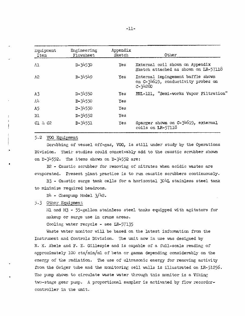
5.0 EQUIPMENT
5.1 l~jor Process Equipment
The major process equipment items are:
Al - evaporator feed tank and high-level waste diversion tank
A2 - evaporator, normally for neutralized intermediate-level waste,
but also capable of concentrating acidic high-level wastes
A3 - vapor filter to obtain the maximum decontamination factor (D.F.)
from evaporator overhead to condensate. This unit is patterned on
Brookhaven National Laboratory data partially covered by BNL-121.
A4 - condenser for vapor from A3.
A5 - condensate monitoring, surge, and diversion tank.
Bl - emergency condenser for high-level waste storage tank Off-gas.
Cl & C2 - high-level waste storage tanks.
These items are located as follows:
Cell I - Al andA2
Cell II - A3, A4, and A5
Cell III - Bl
Buried - Cland C2, each inside a stainless steel clad mild steel tank. Each of these items will be fabricated from 304L stainless steel. The
fabrication quality, with particular attention to welding and testing, will
be equivalent to that illustrated by Specification CT 1.1, nSpecii'ication for
Welded 'l'ype 304L Process Equipment," -which is included in the AppendiX. The
Engineering and Mechanical Division Specification PS-13 might also be con
sidered a quality guide.
Information on the individual equipment items is presented:
Engineering Flowsheets
Unnumbered sketches in Appendix
C-34280, C-34619, LR-57ll8
Equipment Item
Al
A2
A3
A4 A5
Bl
Cl &, C2
Engineering Flowsheet
D-34530
D-34550
D"34550
D-34550
D-34552
D-34551
5.2 VOG E~uipment
-11-
Appendix Sketch Other
Yes External coil shown on Appendix Sketch attached as shown on LR-57118
Yes Internal impingement baffle shown on C-34619, conductivity probes on C-34280
Yes BNL-121, "Semi-works Vapor Filtration"
Yes
Yes
Yes
Yes Sparger shown on C-34619, external coils on LR-57118
Scrubbing of vessel Off-gas, VOG, is still under study by the Operations
Division. Their studies could conceivably add to the caustic scrubber shown
on D-34552. The items shown on D-34552 are:
B2 - Caustic scrubber for removing of nitrates when acidic wastes are
evaporated. Present plant practice is to run caustic scrubbers continuously.
B3 - Caustic surge tank calls for a horizontal 304L stainless steel tank
to minimize required headroom.
B4 - Chempump Model 3/4s.
5.3 Other Equipment
M1 and 1-13 - 55-gallon stainless steel tanks equipped with agitators for
makeup or surge use in crane areas.
Cooling water recycle - see LR-57135
Waste water monitor will be based on the latest information from the
Instrument and Controls Division. The unit now in use was designed by
R. K. Abele and F. E. Gillespie and is capable of a full-scale reading of
apprOximately 100 cts/min/ml of beta or gamma depending considerablY on the
energy of the radiation. The use of ultrasonic energy for removing activity
from the Geiger tube and the monitoring cell walls is illustrated on LR-5l256.
The pump shown to circulate waste water through this monitor is a Viking
two-stage. gear pump. A proportional sampler is activate.d by flow recorder
controller in the unit.

•
•
-12-
A sampling concept is shown on D-34276. This system is a modification
of the Thorex system to allow for the local conditions; particularly, the
necessity for shipping samples to the analytical laboratory in a shielded
carrier.
6.0 PIPING
6.1 General
Process piping and the service headers tying into the process are shown
on engineering flowsheets No. 1 through No. 5 - Dwgs. D-34530, D-34549,
D-34550, D-34551, and D-34552. In addition to the service headers shown on
these drawings, the following systems are required:
Fire Protection System
Hot and Cold Potable Water
Low Pressure Steam for Ventilation Air Heating
Sani tary Sewer (Change Room)
Tne instrument air header for all the instruments indicated in the engineering
flowsheet will take its supply from the indicated building air header as
specified by the Instrument Division.
Attention must be given in the design of pipe runs to sealing against
air leakage where the piping system penetrates from one portion of the build
ing to any other. In addition, sleeves from the Crane Area to the cells must
consider radiation as illustrated in the Appendix. These sleeves are cast
into the concrete during construction and twenty per cent (20%) excess for
each size should be provided up to six of one size for one cell.
In general, all building service supply mains, pressure reducing
stations, flow measuring devices, and other associated equipment will be
located in the Crane Area either north or south of the gantry crane tracks.
6.2 Process Pi~in§
The engineering flowsheets specify all process piping. On these
sheets and the attached piping list, the line numbering system illustrated and
explained below has been used •

..
-13-
II 02 A 2
line:
01 to 19 - process
20 to 39 - service
40 to 59 - pneumatic instrument
60 to 69 - electronic or electrical
point of origin
Specification:
A. All welded 304L stainless steel pipe, example of detail specification,
included in Appendix;
B. For electronic and/or electrical runs such as stainless sheathed thermo
couples and stainless-in-cell conduit. Junction boxes are located outside of
cells.
C. For pneumatic instrument lines using tubing, tubing connectors and
tUbe-to-pipe adaptors. The sleeve into the cell and all runs inside the cell
are stainless. Plastic tubing may be used in the secondary containment areas.
Piping in the secondary containment zone follow standard industrial
practice with special air-sealing attention where the pipe passes through
walls separating areas.
6.3 Miscellaneous
6.3.1 Safety Showers with Combination qe Wash. Three such units are
required: one in Sampling area, one in Crane Area, and one in the Operating
Area.
6.3.2 Drinking Fountain. One located within the Operating Area should
suffice.
6.3.3 Hose Bibs. Three I-in. size are required for cleanup operations:
two in the Crane Area and one in the Sampling Area.

-14-
6.3.4 Fire Protection. All interior spaces in the building, except the
cell interiors, shall be served by fire protection facilities as follows:
(a) A wet type sprinkler system conforming to the latest
standards of NF.PA No. 13 and shall include a monitor with connections to the
existing ORNL fire alarm system.
(b) A system of standpipes and hose cabinets located throughout
the building so as to serve single level floor areas and not to exceed 95ft
from the nearest cabinet. All standpipes and hose cabinets shall conform to
standards NEFU Pamphlet No. 14 and ORNL Dwg. C-20788.
(c) Auxiliary fire alarm boxes shall be installed adjacent
to each hose cabinet along with the required alarm equipment for the wet
type system.
(d) A Siamese t,ype Fire Department connection shall tie into
the standpipe and sprinkler systems above ground level where the main enters
the building. This location must be accessible to the Fire Department. A
valve with post indicator shall be installed at least 20 f't from the face
of the building. No connections other than fire protection purposes shall
be permitted dO'W!lstream from this valve. All outside water supply shall con
form to Factory Material Engineering Division Specifications.
(e) Potable wter from the existing ORNL plant distribution
system shall supply the fire protection system.
6.3.5 Underground Lines. Drawing E-346l8 shows possible runs of all
underground lines called for by the Engineering Flowsheet and the runs illustrated
are not necessarily the best course for any particular line. This drawing
supersedes the information in F. E. Harrington's April 6, 1961, letter to
J. A. Murray, Jr. In laying out these lines, the ORNL Atlas and the drawings
listed below are good references. The connections to bring high-level waste
from 3019 and 3517 are shO'WD. from Wl9 and 8324, respectively. The line from
3019 to Wl9 is sho'W!l on:
D-32204 - Plot Plan
D-32205 - Profile
D-32206 Sections & Elevations
D-32210 - Junction Box 1
D-322ll - Junction Box 2
D-322l4 - Junction Box 3

-15-
'llle thin:dng is W19 "lill be the 3019 monitoring tank. At this point the
waste must be monitored and its disposition to the high-level evaporation and
storage or 3517 feed decided. No firm decision that this plan will be used
has been reached. For the Cost Estimate, the length of run and the necessary
tie-ins should be equivalent to any plan finally adopted. S324 is the 3517
waste disposal tank. Present plans are for the current discharge to W5 to be
valved so that waste may be routed to W5 or to the high-level storage. The
two lines carrying feed to the evaporator from W5 and concentrate to the
concrete storage tanks are shown on D-31.1620. Drawing D-19809, "Alterations
to the Tanle Farm Transfer Lines," shows the present MOyno pump and valve
pit one of these lines must tie into. Schematic Drawing C-34620 shows the
valve arrangement required at this facility.
"(.0 ELECTRICAL
7.1 General
The main distribution and load center for the building electrical system
shall be located in the operating area.
All in-cell electrical systems shall be of vapor-tight construction.
Normal construction will be used for the remainder of the plant.
No Irrreways, distribution or breaker panels are to be located within
any cell. Tne necessary wall or other surface penetrations both here and
between secondary containment zones will consider the need for containment
air seals and possible contamination cleanup.
7.2 Lighting and Wall Receptacle Requirements
Lights shall be installed to provide the 50 and 30 ft candles at work
inG elevations in the Operating Area and the remainder of the plant, re
spectively. Duplex wall receptacles, 15 amp, shall be provided as follows:
Area 220 v 110 v
Change Room 3 Operating Area 1 3 Sample Area 1 2
Crane Area 4 8
The Engineering Department will determine if regulated constant 110 v wall
receptacles are required for hand and foot counter, air monitors (CAM's),
and monitrons.
-16-
7,3 Welding Receptacles
One 60 amp, 440 v, weatherproof receptacle shall be located in each of
the following locations: (a) Operating Area, (b) Sample Area, (c) east
end Crane Area, and (d) west end Crane Area.
7.4 Special System
(a) fire Alarm System. The fire alarm system shall be master-auxiliary
Gamewell type with master at main entrance. Annunciator and dualarm cabinet
are used. Master box is to be Game~ll No. 9000 surface or No. 9103 flush,
three-fold, non-interfacing for 48-volt supply. Code wheel will be supplied
by ORI:iIL. Auxiliary boxes are to be Gamewell No. 9114 surface or No. 9ll4B
flush. Annunciator is to be as per attached Dwg. D-26450 manufactured by:
Gamewell. Duralarm evacuation horns give cO'lll)?lete coverage of personnel
areas, The entire installation is to be in accordance with NFBU requirements.
(b) Intercom System. A radially designed conduit system shall be
furnished connecting the areas listed below. It shall be a master-call type.
Change Room
O:Perating Area
Crane Area
Sampling Area
(c) Telephone S;zstem. A conduit system (with pull wires installed)
for the Bell Tel~phone System shall be designed with outlets within the Operating
Area.
(d) Evacuation S;zstem. A conduit system with radial speaker distribution
is to be designed for the evacuation P.A. system (installed and maintained by
Bell Telephone). This system shall be tied into the building emergency scram
system. When the emergency scram button is actuated, the evacuation of all
building personnel and the ventilation changes outlined in Sect. 4.1 shall
occur simultaneously.
(e) Emergency Lighting;. :Emergency lighting shall be designed for safe
shutdown and evacuation utilizing self-contained, portable, self-charging and
automatic initiation battery-powered lamps.
(f) Electrical Power. All known power users are:
30 hpf'an and pumps- .recirculating water system
Chempump - VOG scrubber liquor
-17-
Viking pumps - monitoring process water
Two agitators - mak~up tanks
Dri ve for gantry crane
Capacity for about 20% increase should be provided.
8.0 INSTRUMENTATION
The Instruments and Controls Division is responsible for the detail
engineering, including cost estimates for all instruments needed for this
project. Part of this phase is discussed in Sect. 3.1 discussion of the
operating area.
The engineering flowsheets are a guide to the bulk of the required
instruments. The nomenclature and symbols used follow I&C Standards. In
addi tion to the items shown on these flowsheets, the following should be
included:
(a) Pneumatic flow recorders for continuously monitoring the total
flow of major building services including VOG and cell ventilation exhaust.
(b) Emergency scram system designed for manual, as well as automatic,
actuation upon loss of negative pressure wi thin the cell exhaust duct. The evapo-
rator steam will be shut off when this signal is actuated.
( c) Two personnel and background monitors (one a H&F unit) •
(d)
( e)
(f)
Four area beta-gamma monitors.
One personnel alpha monitor.
Two beta-gamma CAM' s.
(g) A process waste monitor in the process waste system just below
where this facility discharges into present waste system. This instrument
will be the unit now being developed tUlder D. J. Knowles. A flow recorder
and proportional sampler is an integral part of the "package."
(h) A list of pOints to be telemetered to the new plant mOnitoring
center is included in the Appendix.
(j) ORNL-1513 sums up earlier experience with foam. indication for
waste evaporators.
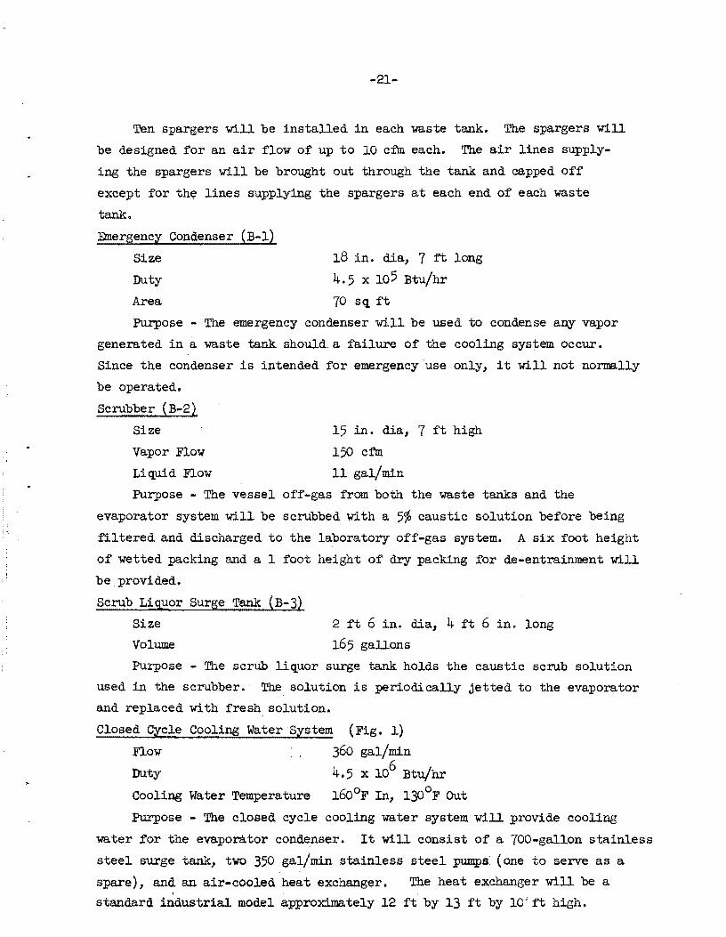
Evaporator Feed Tank (A-l)
Capacity
Size
Material
Cooling Coil
-18-
APPENDIX A
6500 gallons
10 ft dia x 10 ft high
304L stainJ.ess steel
240 ft of 1~1/2 in. pipe, external to tank
Purpose - The evaporator feed tank will be used as a feed tank for the
evaporator and as a hold tank for sampling and adjusting high-level wastes
prior to transfer to the waste tanks.
A coil will be welded to the outside of the feed tank so that the
temperature of the waste solution in the tank can be kept suitably low and so
the tank can be Jieated for decontamination. With the coils welded to the out
side of the tank a leak in a coil will not provide a path fbr the escape of
waste solution outside the cell; hence, no secondary cooling system will be
needed. 200,000 Btu/hr is the probable maximum heat load that will have
to be removed from the tank.
Evaporator (A-2)
Size
Feed Ra.te
Boil-up Rate
Heat Load
Material
Coil
10 ft dia, 12 ft high
600 gal/hr
4500 Ib/hr
4.8 x 10⁶ Btu/hr
304L stainless steel
6 per;manent coils totaling 550 ft2 of heat transfer area
Purpose - The evaporator will be used primarily to concentrate the
intermediate-level alkaline waste solution from the concrete waste tanks.
At some future date it may be used to concentrate acidic high-level waste
solutions. Operation will be semi-batch, with a periOdic discharge of the
evaporator bottoms When the bottoms concentration reaches the maximum feasible
value - probably at a 12 to 1 concentration factor.
De-entrainer
Size 3 ft dia, 17 in. high
Passage width 5/16 in.
Pressure drop (at 600 gph feed) - 10 in. of water
Smallest particle completely removed - 4.2 microns
Purpose - The de-entra1ner will remove the large particles of entrained
~quid from the vapor produced in the evaporator. The design of the
-19-
de-entrainer is developed at Savannah River on high-velocity
impingement caps. The de-entrainer will be built as an integral part
of the evaporator.
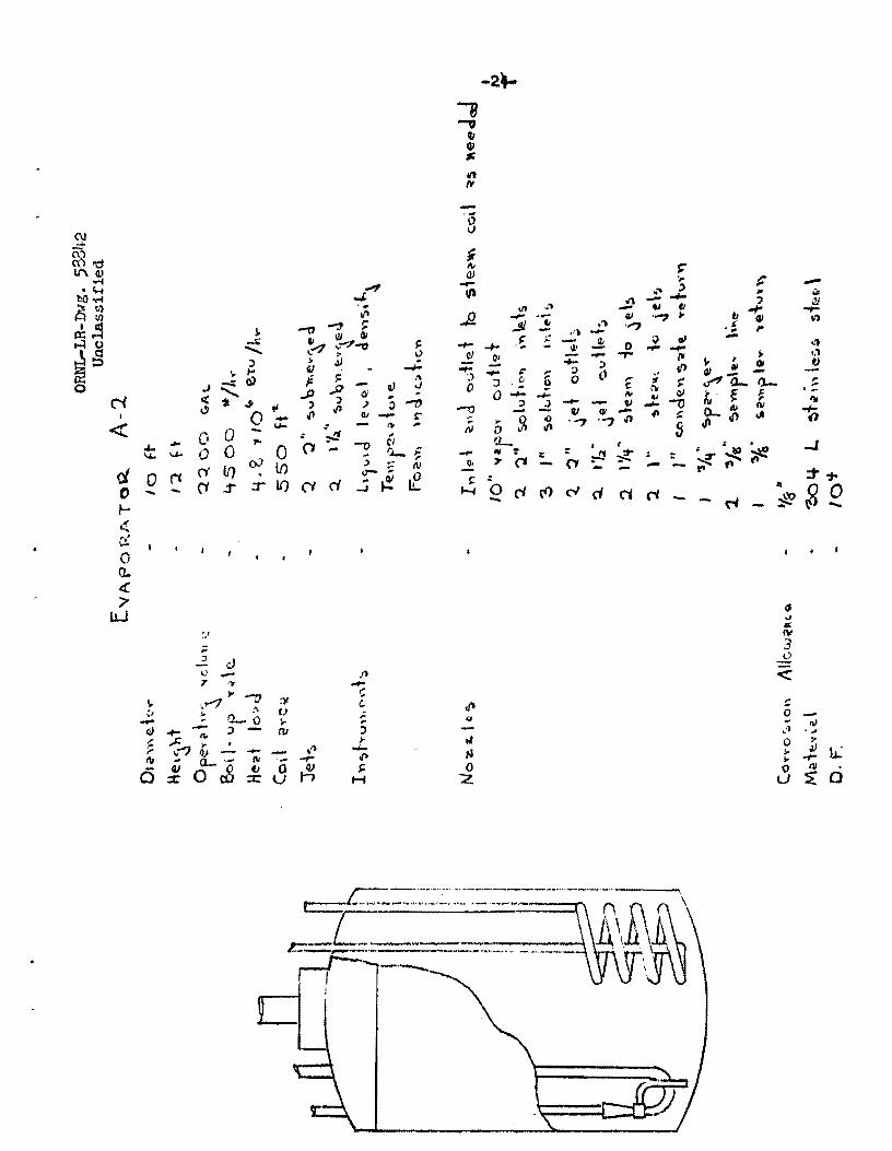
Entrainment Filter (A-3)
Size 4 ft 6 in. dia, 4 ft high
Bed material Stainless steel Yorkmesh, 0.0045 in. wire dia
Purpose - The filter will remove the micron and submicron sized entrained
liquid droplets from the vapor stream. The filter will be mounted outside the
evaporator cubicle and will consist of a thick bed of Yorkmesh made from
small diameter wire. It will be similar to the filter used by BNL on their
low-level waste evaporator. From results obtained with the BNL filter, a
filter decontamination factor of approximately 1000 is expected. Heat losses
from the filter assembly should be great enough to condense a small fraction
(1 to 2%) of the vapor flowing through it, thereby providing a continuous
washdown of the mesh and preventing any buildup of solids. The filter
assembly will be designed for easy replacement of the mesh. The expected
pressure drop is 15 in. of water.
Evaporator Condenser (A-4)
Size
Duty
Area
Cooling water required
2 ft dia, 7 ft long
4.5 x 10⁶ Btu/hr
600 sq ft
360 gal/min at l300 F
Purpose - The condenser will condense the vapor from the evaporator.
Condensate catch Tank (A-5)
Size
Volume
3 ft dia, 3 ft high
150 gal
Purpose - Condensate from the condenser will be collected in the catch
tank and from there will normally drain to the process water drain. A monitor
will measure the activity of the condensate and, if this activity exceeds a
pre-set value (10-5 curies/gal) will actuate an alarm and close a valve in the
process water drain line. The catch tank will then be drained back to the
evaporator until the upset that caused the high condensate activity level
has been corrected.
When high-level waste is being evaporated the condensate will contain
too much activity to be discharged to the process water drain even under

-20-
the best of conditions (a D.F. of 107). In this case the condensate will
be jetted to the concrete waste tanks.
Make-u;J? Tank (M-l, M-3)
Volume 55 gallons
Number Required 2
Purpose - The addition of small quantities of reagents that may be
required will be done through the make-up tanks. Tank M-l will serve the
evaporator and feed tank and M-3 will serve the scrub liquor surge tank.
High-Level Waste Storage Tank (C-l, C-2)
<
M
Volume
Size
Expected heat load
Maximum heat load
Cooling system
50,000 gallons
10 ft dia, 85 ft long
116,000 Btu/hr
400,000 Btu/hr
External Coil, 1900 ft of 1-1/2 in. pipe
Internal Coil, 700 ft of 1-1/2 in. pipe
Purpose - The waste tanks will be used for storage of high-level acidic
waste solutions. One of the tanks will serve as a spare if leakage should
occur in the first tank. Each tank will be contained in a slightly larger
tank (11 ft dia by 86 ft long) fabricated of stainless-steel-clad mild steel
and buried under 9 ft of earth. The outer surface of the outer tank shall
be coated with Koppers Bitumastic.
Each tank will be cooled by two sets of cooling coils, one inside and
one outside the tank. The cooling coils inside the tank are intended for
emergency use only and will not be connected to a cooling water supply or
drain. The ends of the coil will be brought outside the tank and above
ground and capped off. The internal coil will be a staggered arrangement
of 1-1/2 in. pipes running the length of the waste tank at about 1 ft off
the bottom. Adjacent lengths of the coil should be spaced 1 ft apart
horizontally and 6 in. vertically. Seven runs of pipe will be required
for a total length of 700 ft.
The cooling coils outside the tank will consist of lengths of 1-1/2 in.
pipe welded horizontally along the outside of the tank. There should be
nine lengths of pipe spaced 1 ft apart on the bottom and lower sides of
the tank and five lengths of pipe spaced 18 ft apart on each upper side.
The bottom lengths are to be piped so that COOling water flows through
three coils in parallel, each coil consisting of three lengths of pipe.
On the upper sides the flow will be through five lengths in series.
-21-
Ten spargers will be installed in each waste tank. The spargers will
be designed for an air flow of up to 10 cfm each. The air lines supply
ing the spargers will be brought out through the tank and capped off
except for th~ lines supplying the spargers at each end of each waste
tank.
Emergency Condenser (B-1)
Size
Duty
Area
18 in. dia, 7 ft long
4.5 x 10⁵ Btu/hr
70 sq ft
Purpose - The emergency condenser will be used to condense any vapor
generated in a waste tank should a failure of the cooling system occur.
Since the condenser is intended for emergency use only, it will not normally
be operated.
Scrubber (B-2)
Size
Vapor Flow
Liquid Flow
15 in. dia, 7 ft high
150 cfm
11 gal/min
Purpose - The vessel off-gas from both the waste tanks and the
evaporator system will be scrubbed with a 5~ caustic solution before being
filtered and discharged to the laboratory off-gas system. A six foot height
of wetted packing and a 1 foot height of dry packing for de-entrainment will
be provided.
Scrub Liquor Surge Tank (B-3)
Size
Volume
2 ft 6 in. dia, 4 ft 6 in. long
165 gallons
Purpose - The scrub liquor surge tank holds the caustic scrub solution
used in the scrubber. The solution is periodically jetted to the evaporator
and replaced with fresh solution.
Closed Cycle Cooling Water System (Fig. 1)
Flow 360 gal/min
Duty 4.5 x 10⁶ Btu/hr
Cooling Water Temperature 1600F In, 1300 F Out
Purpose - The closed cycle cooling water system will provide cooling
water for the evaporator condenser. It will consist of a 700-ga11on stainless
steel surge tank, two 350 gal/min stainless steel pumps (one to serve as a
spare), and an air .. coo1ed heat exchanger. The heat exchanger will be a ,
standard industrial model approximately 12 ft by 13 ft by 10 1 ft high.

160°F
A421A3
Air Cooler Simifar to Trane OC-6 4.9 x 10⁶ 8tu/hr Heat lood
15-1/2 x 15-1/2 x 10 - W x l x H 330 GPM, - 30 hp Fan
1300F
750-Goflon Surge Tank
<:entri fuga f Pumps Flooded Suction 20 psi Discharge
330 GPM
UNCLASSIFIED ORNl-lR-DWG 57135 Ri
M20A3
From To D-~50 D~50
Fig. l. High and Intermediate level Waste Facility - Schematic Cooling Water Recycle.
I
~

-23-
,..I
~ ""! -"-4
~~ ffi! /"'"
i g -I
< 0 '-"
,. ~. e. .-S 0
0" 4)0 (i
':J. ~
\~
0 1;.1
,. - 0 0
~3-1 - :'k' \t
0 0 .!J J
t t. ..0;., 0 oJ
0 0 ,.
0 '..0 0 .,.. :r
" t
U) 0 - (i -:P tP J - - ~ -~ l -
~ .t\
~ -.. (','/
, ., 0 to-e! (t 0 " N ~ ~
~
... IP
\~
('\J
~td ll'\~ ..... -IH
hO ..... .."
.,.J; a:g I lIS j. 1X:r-l -.. t-lu ........ ~g j ., ,..
J -:;:0)
0 ........ N q; "Ji .3 tI ..,
0 I -.... « (I 0 .,.. .... 0 ~ u.. 0 0 1,1..
OJ d. Ii It) It)
0 rc ('i .:T .:::c- It) 0 -r.
'.,
'" -0 -3 ~ QJ GI
~ .,,--:1'-0 f! ~ " > .lJ ..
~ ~
i- s: ,,",
.P Q/ .J ..P Ci ..
) J ;) :> ....,., oj) oil CIt -- '" ~
". ,.. = '"
-0 CI ("I - . Il.... ~ :> .- 1\1 lJ-:;:
at: ('i d .. ~ ...J
- • ~ - :
t= . -
("'I -
~ ",'
""" 0 0-<! '7
JJ..J 0 'oJ $<
~ .. J
- "" 3 ..£
Jl <: .-.;
:: " cP 0 -~ - 1\1 (I ,l ' ... J
0 l' ;- tl ~ iiJ I~
...... ,.a ,. -t-.p 0 III -s:- o u ~ 0 H :z.

O"ERALl.. DIAME::rE.R
HE.\c"Hi
PA~~AGC 'WIOTIi
-25-
j-
.o.f A1' '2>00 GPH E:""PO~ATO\( f"E.t:.O
51'v\P'L.Lt:~T PARnc.Lt: COMPLETE. L'! I<£:MO\l£O
Af> AT 1000 GPH E."APoRAiO\~ rEEO
5"\ALI..E:.~T PAl(n Co\.£' (.OMPL.£.TE\.."( REI\I\O'H!O
MATER.\Al.
ORNL-LR-Dwg. 58843 Unclassified
3 FT
17 'NC.HE~ 5/1~ .N<:.H
-::2.5' INC.\it.$ WATER
f.D "''H C. ~O N $
I C ,~eK\'::~ WATt:.~
Lt • 'l. MI c. (:lON ~
30'i 1. 5TAINLE'S~ STEEL.
104 't'----,
\ lX(' IX· 6<'\"" I
: ,; I ,J I '/ I /''- i /
'/ \/ f / ,.- ! \/, / , \' "/" \/\/ i .',/ /\/"
\X/'X'X\/, ,,' ,\/ \; ; 1\/ X' ,\' '\ ;\ t\ " , /\ .. l. '/ "I .,! I '\/ \,' , .. " 1. ... ,"" /\ /' '\;\ i\ J > ' I' \/ '. ! 'L/ /.~ ~,' /\ \~ ~ \. \.)\ \ / \/\/\>~., 7'/' '/\ l .. /"X' \; " . X " '. \' , ,
1\ ;' \ ,/ \ \ /",
're"\, \1\\~''i 'St."~C'n ,
______ _.__ .... - .•. - -.. --~ a
ORNL-LR-Dwg. 58844
F UnclJj.ss1:f1e~
ILTE:.R fo~ E"IA"oRATO~ \1I-\fI'o~ \A-3}
O"'~'r"\\ O\2W\Q.\e.'i"
Q ... e.,<"lI \\ He.\\ '"'~ B!:!J. O\a\),~ ~e.\-
, It
4- Co
,+'
.... ' S' Sed He.\~"i
Sed. JV\'l.\e..v'~\ Shin \e<:;,~ 5 le.e.\ "(o ... \7:mQ.~'" (0.0045 "CAH~)
?/
~Il'~ b~ HI.~ ! L.
Noz.-e\Q.s
N\.de'Y'\~ \ of Con'!> \"'I..Ie.. \IOYj -
10" 'fe~
10" "~F'" I" d .... 'e\·Y\
'Y\ \e. -\ ( \)0 \\Ol"ft )
e~~+ (top) ( 'oc::dfo\l\)
004 L ~iOli\, le~s ~ le.Q I
~

-27-
OltNL-LR-Dwg. 58845 Unclassified
~ ';:~c=;:====~ ____________________________ ~~~~
['1APO\~ATO~ CQNOE"SE~
DU\J
A·(e~
lel\~~ Tu be ~,z.E'
Tu\)e. 'hu~,be. ...
R-e.,,-;, u". Over (..,;afOr ':lid.) Ceo I i'~l W;t\e... ,. e..7 u''''HJ Na'Z.z.l~:;,
(A- it)
~.S ., lOt. eru/ ....
1000 n'L to ft
.. "1", of
..s~o
o.s i¥\e.lu!$ 1o\J,,~.r
'3 bO CJ.,a'/wlI" ® \3d .. ,,,l.,\-.. /0" ... -po". ,~ lei
'1:1" C.b"J~W\,.\e outlet ",II + .« ""'1'\ -a" c.oo"" klate". ,,,,lei 3 .. c.c()"'.~ ""a.t... cuHet aolt L.. ~t.,'1'\ Ie...... fa te.e 1

7j ve"iT
M_~T<>~ r 1
"'0 'WI\POAATOIit
.. I
To '\N-S
::::rn -r-::J~
;; rA.oN\ ! I C.O"'DC.N~e:R I ! I Ii ! f
----11 II-- It--'
t :RI"LDW To
!II\PO«-' Toll'
--To ffloC.s~~ ! WA'5iT£ ----.. $oi$ TI.'l'"
OIAM\'::iER.
He::\GH T
Vo\..ur.t\~
CON DEN SAT£.
NORMAl.. OPERATING "C\..O,.,\~
::re.T~
1"" ~T~ u 1'1\ ~N 't~
No. t:.4lE~
MI\ TERIA,\..
ORllL-LR-INg. 58846 Unclassi:fied
CATC.~ TA.NK (A -5)
3 FT
-:0 FT
150 <::'AL.
10 10'" l.. 3.1. .,
Q l't
LI!""~L. IliO' <:.A TIO Ii
TEMPEf(ATUQ.~ llio\c,ATION
, ,. aOTTo,"" OuTLET
, a.
, , , ,
,fa'l
eOiTON\ oun.Ei To MONtTo~
,lIz" rEt: 0 FROM CoN OEI1 S ~lZ
~,." LINE!'! To :re.T~
3/,." FRoM. SUMP :reT
"/8" ~MPL~ 1..1Ne:.
'/:(. S.PAQ.<; C~
," "E"'T ~" Re:Tu~N FROM Mo""ITo~
I" O"e:~FLOW
'304 L ~ TAU" L.\:::SS 5 Tee I.
I f\) co I

-29-
ORNL-LR-Dwg. 58841 Unclassified
~---.--------
Dui~ A .. eil.
, ..
Le":l""' Tvh ~'z.
Tv b~ l'IIJ'r\' ~o,.
Co:> ".y\~ c..nie-. V'e.~ui"'QJ N~:t.z.'~:a
y.. S __ 10$ 8't1J /h ..
70 f\" ~ f+ "3/ .... ,
~o
30 !lrTn 3" '" e fcrt' \'Y'I let , .. c.OY\ de.on ~u ~e OCJtlei
I" 'Ie'f"lT
1'1: .. • , 1 , ~ ""'\ wont. ... '~\e~ I'~" t.oc)"~\ tU~\aV' ouHe.t
'304 L ~toi '\\ I~~~ stee.l

r-et 0
r
~
,-. D 1..J N J-r-
dJ LJ ~ ~ ,n
---" I:J t- 1.1. z I.iJ l- V ,J W tJ
0: % 1.1. t! 0
W I" ~ ~ C9 10
c:9 ::J a:-U
if)
.... -;;: cJ "" 3 W
r:t :z: g w I- l.I.
t- O w :r: W ct ~ t-' :J. 0 .t! - I.l Q.
- IJJ t. « O:z: >
'i::" 'Z
"" () ~ IJ ~ £ I- <:t ~ <C flo LJ
T! ,.... :) 0
~ '" <
'" ",,--£'- -
,,') ..) w U ...J
D ~ 0 t-4: 1/) 1/1
\fl )C \/') -,. 0 liJ '-.. J ..)
f 4:. Z ....... I-.J :z < <: H I-C) III
J :t: ..J 0 . z :t'
0 - 0 - «)
3 0 ..)
IJ.,. \9 J
<! 0 Z ... ... - (j. :J )J W a u - «
t-«
...1(}.. :f
r!)O ., 51;
llg"
~
-30-
'2'1: l?~
.1
O~LR-Dwg. 58848 Unclassified
(f) 0 :) .. (t :J )-v 0- ;) \1)::'0
---flo

~ To ~tC.U:otc..u\.~TII""
PUMP
DIAM~Te~
LENc"l'H
TOTAl "OluM£:
OPf:RAT INC. VOLUM~
::rET
lN$T~UMENT'~
MATER\AL
"'tNT
..
-31-
Fe-EO t"\rROM
Stque~\tR
~ 'A. FT
4 1/" FT
I ~ 5 C.AL.
ORNL-LR-Dwg. 58849 unclassified
! I F'~OI'l\ RUCtHT""\. wt-\P AOOlTlON ~ET
( 6-3)
I '0 C C,AL
'&/"1' "
It'lEL. lilt 01 c..ATlON
DEN'S'''''' IN 0\ c..ATION
T E M P to ~ ATu R £. IN 0' c:.AT( ON
I "u" ~ eo,TO~ O\~~"A~~E , r" VENT , ,. ~ET ~vc..T'oN
I .. FEt.O FROM :"<:'R.uee~~
'318' ~AMPLEQ. L'NC
'/a" RE I\G Er;T 1\001'1"°'"
-:sAt" FRo~ ~UMP "SET
00'+ L STAI""LE~~ STe:EL.

R£:(l,UI."~ OFf· "'Afl
-32-ORNL-LR-Dwg. 58850
Unclassified
LI'IIC "---c:: ___ .. _ .
LA~ ~£ o,r· c.1\~ lINt~ ___ _
D\I\METE((
lE.N Co TH
70TA \.. 'JO\.UMC
(")PERAT'NC, \lo\"UM-r
E)(Pe:c.Teo HEAl LOA.D
Mj)"~IN\vf'.\ HeAT LOAQ
INTe:.RNA L c..OI \.
t)lT~RNA\.. <:01\,.
CO~~O~'ON "L\.OwANc'~
NORMA \.. OFF'- ~A.'i;t FLOW
EMe:~C.~NC.,. tIFF- «0"$ 'LOW -
NVN\\3(;;~ oF' ~PAa<:'CR"a
~£T~ •
IN'$T~uMi!:NTATION
Noz~\..e.~
T~~~li\1t
-==, .. " ... ··",....".,...·.,.,S \ , ,
10 F"
I g..s PT
50,000 G4t..
Ito,ooo Q.4\
"<'. 000 '6Tfj
/Mrt..
400, ooe STu/ft~ 7 h:fl/CTH $ of I "a t. p.pe ( ..... 700 PT TOT4 ... )
19 LE:Nc::.rl\S Qf"' I'/:t PH':IIi; ( .... l<toO 'FT TOTA\,.)
'/S'I
4 (.tr~
8s <:.,"" 9 (Au. euT 2. ARE gl:.cca-."Et..TeO)
~ - "At ~S""'£.Q~ EO
lE"C!\.. I C"N~'l'Y I TEI\I\P£.AATuRE:
10 5/'t"" PARCEQ.!1
:l J ./ ~TeAfoI\ ' .... \..en, To 'J'e: T'!.
:t. , ', ..... ~£'T OvTL£'T~ , ON": C.A~~-=O
I I" ftEO L'NE '(~PA\tti.) ~ ., fEEO L'NE F'ltOM '<lAL'I£ PiT
I "." FEED LaNe: FRoM OTt\E\~ T~HK. , ,M rE.to L.\NE FRoM $UMP
• Q'!:I.'I orr- G"'~ '-11'1£
. I Ilia - f'£EQ L. a"" e: P"Q.CM A· ,
~ 31&1. ~AMf'L'"(j, ","e~
'l Illa" ,Coo,-,,..c. 'WI\Te.R. '-IN£'$

t VENT
PROC.~S 'WATER ~r AOOITICN l
~ II " H I' 11 ,)
f I I I I I I
<:::.k':J
!
I I
MA~E - uP
Yo I..UM 'E
l~~T'\(UMC.NTS
No'Z.1:.I...C~
MATERIA\...
ORNL-LR-IJrIT~. 58851 Unclassified
TA N ¥-. (M-l I f''\~3)
I
I
I
55 GAL
l E '" £: \.. t N \) \ c.;.. T ~ '). n t/';l. " BOTTOi'.' OI'::{A.\N
I" VENT
'h. " WATE'i< AOOITICN
I t( R~A G t.NT AOClTIOI1
'304 L STAINLE~~ 5TEEl..
I W VJ
I

-34-
APPmDIX B
JET LIST
Jet Function Size,! in.
AI-Jl Al to Cl 1-1/2
AI-J2 Al to C2 1-1/2
AI-J3 Al to Valve Pit ( capped) 1-1/2
Al-J4 Al to Valve Pit (capped) 1-1/2
AI-J5 Al to A2 1
AI-J6 Al to A2 1
A2-Jl A2 to Cl 1-1/2
A2-J2 A2 to Valve Pit to w-6 2
A2-J3 A2 to C2 1-1/2
A2-J4 A2 to Valve Pit to W-5 2
A5-Jl A5 to A2 via A507Al 3/4
A5-J2 A5 to Valve Pit to Tank Farm 3/4
A7-Jl A7 to A5F 3/4
A6-Jl A6 to Valve Pit to Tank Farm 3/4
B6-Jl B6 to B3 3/4
B3-Jl B3 to A2 3/4
CI-Jl Cl to Valve Pit ( capped) 1-1/2
C1-J2 C1 to C2Q 1-1/2
C2-Jl C2 to Valve Pit ( capped) 1-1/2
C2-J2 C2 to CIQ 1-1/2
C3-Jl C3 to Valve Pit ( capped) 1-1/2
C4-Jl c4 to Valve Pit ( capped) 1-1/2

-35-
APPENDIX C
PIPING LIST
1. Process PiJ2ing
A. D-34530
Line Number Function and Comments
AlOl-Al-l/2 Al-Jl to ClE AlD (see Al6IB) AlO2-Al-l!2 Al-J2 to C2E AlC (see Al62B) AlO3-A2 Inlet from Valve Pit AlE AlO4-A2 Inlet from Valve Pit AlF AlO5-Al Al-J5 to A2H AlW (see Al65B) AlO6-Al Al-J6 to A2H AlX (see Al66B) AlO7-Al-l/2 Al-J3 to Valve Pit AlA AlO8-Al-l!2 Al-J4 to Valve Pit AlB AlO9-A-3/4 Inlet for Future Carrier AlT
Unloading AllO-A-3/8 Sample Suction AlNa Alll-A-l!4 Sample Airlift Air AlNb Al12-A2 Spare Inlet from East AlV
Valve Pit All3-A2 Inlet from W5 via East All
Valve Pit All4-A2 Inlet from W5 via East AlG
Valve Pit All5-Al-l/2 Vent AlH (see BOO 3A2) BOO3-A2 VOG Header MlOl-A-l/2 Ml to Al V Solution Addition MlO2-A-l!2 Ml to A2F Solution Add! t ion
A60lA-3/4 A6-Jl to East Valve Pit (see A660B) A6l0A-3!8 Sample Suction A6llA-l/4 Sample Afrlift Air
B. D-34559 AOOl-AlO Vapor to A3B A2R A202-Al-l/2 A2-J3 to Cl A2X A203-A2 A2-J4 to East Valve Pit to A2D
Moyno Pit A204-A2 A2-J2 to East Valve Pit to w6 A2E AOO5-Al-l/2 A2-Jl to C2 A2W Aoo6-A2 Inlet from MOyno via East A2Y
Valve Pit A207-A2 Inlet from Jet via East A2Z
Valve Pit A208-A3/4 Water to Spray Nozzle A2b A2l0-A-3/8 Sampler Suction A2M3 A2ll-A-l!4 Sample Air A2M2 A2l2-A-3!4 Sample Return A21>U

•
D.
E.
Line Number
B. D-34559 (Cont'd)
A302-Al BI02-Al
C. D-34550
A302-Al A301-AlO A303-A2 A401-Al-l/2 A402-A2 A403-Al
A501-Al-l/2 A502-A-l/2 A503-A-3/8 A504-A-l!2 A505-Al A506-A-3/4 A507-Al A508-A-3/4
A510-A-3/8 A511-A-l!4 A701-A-3/4 A710-A-3/8 A711-A-l!4
D"34521
ClOlA-l-l/2 CI02A-l-l!2 CI03A-2-1/2 CI04A-l-l!2 CIlOA-3/8 ClllA-3!8 Cll2A-l/4 Cll3A-l!4 CI05Al clo6A2 A205A-l-l/2 C30lA-3/4 C3l0A-3!8 C31lA-l!4
D-24621
C20lA-l-l/2 C202A-l-l!2 C203A-2-l/2 C204A-l-l/2
-36-
Function and Comments
Inlet from A3C Bl to A2 Condensate Drain
A3C Drain to A2Q A3A to A4A
A2Q A2F
VOG to Bottom A3 for Filter Change A4E Drain to A5A A4D A4 Vent to B202A4 or 320lA4 Vent so that A40lAl-l/2 is Always Sealed from A5
A5P Drain to Plant Low-Level Waste System A5 Pump Suction from A5Q A5 Pump Discharge to Monitor Monitor Drain to A5N A5M Vent A5-J2 Suction and Discharge A5C A5R Overflow to A302Al A5B A5-Jl Suction and Discharge
A5E Sample Suction A5D Sample Air A7-Jl Suction and Discharge to A5F A7 Sample Suction A 7 Sample Air
CI-Jl Discharge to Valve Pit -Cl-J2 Discharge to C2F Emergency VOG- CIN Cl VOG Cl Sample Suction Spare Cl Sample Suction Air to CIIOA-3/8 Air to ClllA-3!8 Spare Inlet from Crane Area Inlet from Valve Pit Inlet from Valve Pit Cl-Jl to C2R C3 Sample Suction Air to CIOA-3/8
C2-Jl Discharge to Valve Pit C2-J2 Discharge to C2F Emergency VOG - C2N C2 VOO
ClKl C1K2 Nozzle
ClLl ClL2 C1L3 C114 CIS CID
C2Kl C2K2 Nozzle

I'
-37-
Line Number Function and Comments
I ' E. D-34621 ( Cont r d)
C2l0A-3/8 C2 Sample Suction C2Ll C2llA-3!8 Spare C2 Sample Suction C2L2 C2l2A-l!4 Air to C2l0A-3/8 C2L3 C2l3A-l/4 Air to C211A-3/8 C2L4 C205Al Spare, Inlet from Crane Area C2S c206A2 Inlet from Valve Pit C2D A202A-l-l/2 Inlet from Valve Pit CL~lA-3/4 C4-Jl to C2R C4l0A-3!8 c4 Sample Suction C4llA-l/4 Air to C40A-3/8
F. D-34552
B1OlA-2-l/2 Cl and C2 Emergency VOG BlA B102A-l Condo Drain to A2 BlE to A2F B103A-2 Bl Vent BlD to B202A4
B20lA-4 B2A VOG Scrubber Outlet
" B202A-4 B2C VOG Inlet to Scrubber B203A-2 VOG for Cells to B202A4 B204A-2 VOG for Cl & C2 to B202A4 B205A-l B2D Drain to B3D
I B30lA-l B3 Drain to B4 Pump J B302A-3/4 B4 Pump to B2B ;1
B303A-3/4 B3-Jl suction & Discharge to A2 B3B B304A-l B3A B3 VOG B3l0A-3/8 B3llA-l/4
B3C Sample Suction Sample Airlift (to B3l0A-3/8)
B60lA-3/4 B6-Jl suction & Discharge to B3J B60lA-3!8 Sample Suction B611A-l/4 Sample Airlift (to B6l0A-3/8)
M30lA-l/2 M3 to B3C
II. Service Pil2in~
A. D-34530
Al20A-l Steam to Al-Jl A1J Al2lA-l Steam to Al-J2' Ali(
Al22A-l Steam to Al-J3 AlL Al23A-l Steam to Al-J4 AlM Al24A-3/4 Steam to Al-J5 AlS Al25A-3/4 Steam to Al-J6 AlU Al26A-3/4 Air for Sparger A1Q Al27A-l-l/2 CW to AlY (note FE) Al28A-l-l/2 AlY to Drain (note TL)
"
Line Number
A. D-34530 (Contd)
A620A-l/2
Jet Vent Header 2"
-38-
Function & Comments
Steam to A6-Jl
Air bleed to jets to relieve any suction caused at end of jetting
Process Water Drain To Storm Sewer Building Steam 4" 125 psig steam Jet Steam Header 2" 65 psig steam Process Water Header 3" Building supply
3"
Air Header 1" Plant Air
B. D-34549
A220A-l-l!4 A221A-l-l!4 A222A-l A223A-l A224A-l A225A-l A226A-l-l/2 A228A-l-l!2 A230A-l-l!2 A232A-l-l!2 A234A-l-l!2 A236A-l-l!2 A227-A-l-l/2 A229A-l-l!2 A231A-l-l!2 A233A-l-l!2 A235A-l-l!2 A237A-l-l!2 A238A-3/4
c. D-34550
A420A-3 A421A-3
A520A-l!2 A52lA-l!2 A522A-l!2 A720A-l!2
D. D-3455l
Cl20A-l-l!2 C121A-l-l!2 C122A-l-l!2 C123A-l-l!2 C124A-l-l!2 C-125A-l-l/2
Steam to A2-J2 A2J Steam to A2-J2 A2L Steam to A2-Jl A2U Steam to A2-J3 A2V Condensate Steam to Process Drain A2Sl Condensate Steam to A2 Coil A2S2 Steam or H20 to A2 Coil A2Al Steam or H20 to A2 Coil A2A2 Steam or H~ to A2 Coil A2A3 Steam or H20 to A2 Coil A2A4 Steam or H2O to A2 Coil A2A5 Steam or H20 to A2 Coil A2A6 Coil to Trap to Process Drain A2Bl Coil to Trap to Process Drain A2B2 Coil to Trap to Process Drain A2B3 Coil to Trap to Process Drain A2B4 Coil to Trap to Process Drain A2B5 Coil to Trap to Process Drain A2B6 Air Sparger A2L
CW to A4c A4B cw to Drain
Steam to A5-Jl Steam to A5-J2 Air Sparger Steam to A7-Jl
Cooling Water to Coil Cooling water to Coil Cooling Water to Coil Cooling Water to Coil Cooling Water to Coil Cooling Water to Coil
A5L
1 2 3 4 5 Internal Coil

-39-Line Number Function and Comment
D. D-3455l (Conttdl
C126A-l-l!2 Cooling Water to Drain 1 C127A-l-l/2 Cooling Water to Drain 2 C128A-l-l/2 Cooling water to Drain 3 C129A-l-l/2 Cooling Water to Drain 4 C130A-l-l/2 Cooling Water to Drain 5 C13lA-l-l/2 Capped C132A-3!4 Air to Sparger 1 CH30A-3/4 Air to Sparger 9 C133A-3/4 Future Air to Sparger 2 C134A-3/4 Future Air to Sparger 3 C135A-3/4 Future Air to Sparger 4 C136A-3/4 Future Air to Sparger 5 C137A-3/4 Future Air to Spa.rger 6 C138A-3/4 Future Air to Sparger 7 C139A-3/4 Future Air to Sparger 8 C18lA-l Steam to Cl-Jl Jet c182A-l Steam to Cl-J2 Jet C320A-l/2 Steam to C3-Jl
E. D-3462l
C220A-l-l/2 Cooling Water to Coil 1 C22lA-l-l/2 Cooling Water to Coil 2 C222A-l-l/2 Cooling Water to Coil 3 C223A-l-l/2 Cooling Water to Coil 4 C224A-l-l/2 Cooling Water to Coil 5 C225A-l-l/2 Cooling Water to Coil Internal Coil c226A-l-l/2 Cooling Water to Drain 1 C227A-l-l/2 Cooling Water to Drain 2 C228A-l-l/2 Cooling Water to Drain 3 C229A-l-l/2 Cooling Water to Drain 4 C-230A-l-l/2 Cooling Water to Drain 5 C-23lA-l-l/2 Capped C-232A-3/4 Air to Sparger 1 Cl80A-3/4 Air to Sparger 9 C233A-3/4 Future Air to Sparger 2 C234A-3/4 Future Air to Sparger 3 C235A-3/4 Future Air to Sparger 4 C236A-3/ 4 Future Air to Sparger 5 C237A-3/4 Future Air to Sparger 6 C238ft-3/4 Future Air to Sparger 7 C239A-3/4 Future Air to Sparger 8 C28lA-l Steam to C2-Jl Jet c282A-l Steam to C2-J2 Jet C420A-l/2 Steam to C4-Jl
F. D-34552
Bl20A-l-l/2 BIC CW Inlet Bl2lA-l-l/2 BlB CW Outlet B320A-l/2 Steam to B3-Jl B620A-l/2 Steam to B6-Jl

-40-
III. Instrument and Electrical Piping
Line Number
A. D-34530
AI40c-3/8 AI4IC-3!8 Al42C-3!8 Al43C-3/8 Al60B Al61B Al62B Al63B Al64B Al65B Al66B Al43C-3/8 Al44C-3!8 A640C-3/8 A660B
B. D-34542 A240C-3/8 A24IC-3/8 A242C-3/8 A260B A261B A262B A263B A264B A265B A266B A267B A243C-3/8 A268B
c. D-34550
A340C-3/8 A34IC-3!8 A342C-3!8 A440c-3!8 A540c-3!8 A54IC-3!8 A542C-3/8 A543C-3/8 A560B A561B A740c-3/8 A74IC-3/8
Function and Comments
L&D Hi D Lo L Lo Cell Ventilation PI 10 Thermocouple AlR Al-JI Discharge Thermocouple Al-J2 Discharge Thermocouple
AlPa AlPb AlPc
Al-J3 Discharge Thermocouple (Not Connected at Panel) Al-J4 Discharge Thermocouple (Not Connected at Panel) Al-J5 Discharge Thermocouple Al-J6 Discharge Thermocouple VOG Lo (see VOG PI & B203-A2) Cell Ventilation PI Lo A6 L Hi A6-Jl Discharge Thermocouple
L Lo L & D Hi D Lo A2J2 Discharge Temperature A2J4 Discharge Temperature
A2Nl A2N2 A2N3
Conductivity #1 ~ Fbam Indicator A2Pl Conducti vi ty f2. . A2P2 Conductivity #3 A2P3 A2-J3 Discharge A2-J4 Discharge A2 Temperature Air to LCV on Al-J6 Jet Spare Thermocouple
Air to A3 Bypass Valve AP Hi Probe A3 AP Lo Probe A3, Hi Probe A4 dP Lo Probe A4 A5G L Hi A5H L Lo A5J D Lo (Capped) Air to A5 Drain Valve A5K Thermocouple A5 Pump Power Line A7 LS Hi A7 LS Lo & CV Lo
A2Tl 1 A2T2
Line Number
D.. D~34551
Cl40C-3/8 C141C-3!8 C142C-3/8 C143C-3/8
c160B c16lB c162B
E. D-~4621 C2 C-3/8 C241C-3/8 C242C-3!8 C243C"3!8
c260B c26lB c262B
C340C-3/8 C341C-3/8 C440C-3/8
F. D-34552
B240C-3/8 B241C-3!8 B242C-3/8 B243C-3/8 B244c-3/8 B245C-3!8 B340c-3/8 B341C!..3/8 B342C-3/8 B360B B440C-3/8 B460B B46lB :s640c-3/8 C-3/8
-41-
Function and Comments
Cl D Lo Cl L&D Hi Cl Spare Cl L 10
ClPl to TR
ClNl C1N2 ClN3 ClN4
ClP2 to Junction Box, Sheathed Thermocouple ClP3 to Junction Box, Shea thed Thermocouple
C2D 10 C2 L&D Hi C2 Spare C2 L 10
C2Pl C2P2 C2P3
C3 L Hi C3 & C4L 10 c4 L Hi
Air to HCV-B2C on B2 By-Pass Air to Valve B2B .. . Air to Valve HCV-Bl Air to Valve PCV - VOOb :52 P 10 B2 P Hi &VOG Lo L 10 B3E L&D Hi B3F D 10 B36 Thermocouple B3H
C2Nl C2N2 C2N3 C2N4
Air to B4 Pump Discharge Valve from FC-B4 Power to :54 Pump Electronic to Flow Recorder B6 L Hi VOG Hi
Valve Pit Shown on C-34620

-42-
Spec. CT-1.1
Date 5/1/60
Page 1 of 11
APPENDIX D
SPECIFICATION FOR WELDED TYPE 304L PROCESS EQUIPMENT
1.0 SCOPE
1.1 This specification provides data and special requirements for fabrication, inspection, certification and delivery of welded type 304L process equipment as described by the Purchase Oder and the drawings.
2.0 REF ERENCES (Material Standards Covered Elsewhere)
2.1 ASME Boiler and Pressure Vessel Code, Section VIII, Unfired Pressure Vessels, 1959 Edition as amended by later addenda and Case Interpretations, hereafter referred to as the Pressure Vessel Code.
2.2 Code Case Interpretation 1270N-l (not for Classes 2 and 3)
2.3 Code Case Interpretation 1273N (not for Classes 2 and 3)
2.4 ASME Boiler and Pressure Vessel Code, Section IX, Welding Qualification, 1959 Edition as amended by later addenda, hereafter referred to as the Boiler Code Section IX.
2.5 American Standard ASA B 31.1-1955, code for pressure piping, hereafter referred to as the Piping Code.
2.6 Standard of the Tubular Exchanger Manufacturer l, Association, Latest Edition.
(Applicable for heat exchangers only.)

Spec. CT .. 1. 1 Dote 5/1160 Page 2 of 11
3.0 RESPONSIBILITY
3.1 The Seller shall be responsible for the fabrication, inspection and testing of equipment in conformity with the~e spec. Hi cation ...
3.2 If the Seller notes any conflic.t belween specifications and drawings, it is the responsibility of the Seller to notify the Company and await clarification before proceeding.
3.3 The Seller shall notify the Company of an)' details of the drawings and specifications that do not meet the requirements of tht' Pressure Vessel Code.
3.4 The Seller shall, on completion of the work, certify that the equipment conforms in all respect~ to the reql..·;remenh of this ~pecificot:Orl.
4.0 APPROVAL OF THE COMPANY
4. I The Seller shal' submit the following items to the Company for approva~ prior to the actual fabrication of welded parts or assemblie~-. Sel!er must receive approval in writing before work is commenced.
4.1.1 Shop d:awing:,* showing weltllng delailsp internal and external support details.
4. 1.2 Cer~ification that 011 material provided by Seller conforms to this specification. Mill reports,. chec.k anolyses and mechanic.ol te,,'- reports shall be submitted.
4.1.3 Detoiled welding procedures !nd:.!di,r)g e;ert-!fied procedure and performance test reports.
4. 1.4 Deviations from this speclficatton.
4. 1.5 Detai led heat treatment procedure~.
4.1.6 Detailed inc;pecHon and leak testing p!ocedures.
4. 1.7 Detailed procedures for be"ding pipe.
*The Seller shall pay particular attention to the following: (a) the interior and exterior of all equipment shall be free of crevices which could retain solutions or fine particulate materials, (b) the joint design shall be detailed for all .welds which cannot be performed by either single or double butt-welding, and (c) the weld joint design and assemblyinspection sequence for each unit of equipment :shall be selected to offord maximum compliance with the fabrication, in'Spection, and leak testing requirements of this specification.

5.0 STAMPING
Spec. CT -1.1 Date 5/1/60 Page ·3'':!-0 .... f-ll---
5.1 Vessels made under this specification shall be manufactured, Inspected and stamped as Primary Vessels (as defined by Par (5) (b) of Code Case Interpretation 1270N-1) in accordance with provisions of Code Cases 1270N-l and 1273N (class one only).
5.2 Vessels made under this specification shall be manufactured, Inspected and stamped in accordance with the provisions of the Pressure Vessel Code.
6.0 MATERIALS
All type 304L stainless steel products, equipment, and/or components shall be 'as specified on the drawings, or other material procedures, and shall conform to all requirements for that type in the appropriate prodl'ct form specification listed below; together with such alternate provisions or modifications as may be ~tated in this specification. The maximum allowable carbon content shall be ,0.030%.* Check analyses as permitted in the applicable ASTM specifications are required for all ELC grades of stainless steel.
Manufacturers' certification of compliance with ASTM product form specifications shall be furnbhed, the certifications to include results of chemical analyses, corrosion tests, mechanical property determinations, and such other tests as are required by the applicable specifications and these modifications. Teds required by this specification, but not by the basic ASTM specification, may be eertHied by either the Seller or competent testing laboratory. The Company will conduct further tests as described in 6.4.1 on the material to further satisfy himself that the material meets the requirements of this specification.
All pipe and tuqing shall be seamless, conforming in all respects to the applicable ASTM specification designated below.
6.1 Applicable ASTM spedficatDons are as follows:
6.1.1 Sheet, elate and strip - ASTM-A 167-5S (SA 167 modification) or A240-5ST
6.1.2 Seamless and' welded piee - ASTM A312-59T
6.1.3 Seamless and welded tubing
6.1.3. 1 General Service, Seamless and Welded, ASTM A269-59
6.1.3.2 Heat Exchanger Tubing,Seamless - ASTM A213-59T
*class 3 - carbOn"content 0.035% maximum allowable permitted.
•
-45-
Spec. C'( -1.1 Date --"S7""1r"'7/6"'o~-Page 4 of 11
6.1.4 Forgings for flanges, fittings and valves - ASTM A 182-59T
6. 1.5 Bars - ASTM A276-59
6.1.6 Welding Fittings - ASTM A403-59T
6.1.7 Bolti ng
6.1.7.1 Bolts and Studs
Bolts and studs shall conform to ASTM A 193-59T, type 304, and the other requirements of this specification. Studs shall be threaded full length. Type 304L bolts are to be specified if the bolts are to be welded on.
6.1.7.2 Nuts
Nuts shall conform to ASTM A 194-59T, type 303 and the additional requirements of this specification .
6.1.8 Welding Filler Meta!·
6.1.B.1 Bare Rods and Wire
Filler rod:: for use in inert gas shielded consumable and nonconsumable electrode welding shall conform to the requirements of ASTM A371-53T, with ER30BL being used wi th type 304L, except that the carbon content shall not exceed O.0300k.
6.1.8.2 Coated Welding Electrodes
Cooted welding electrodes shall conform to the requirements of ASTM A298-55T, lime coated, Type E30BELC-15i except that the carbon content shall not exceed O.<X3O%.
6.2 Fi nishes
Finishes of sheet, plate, and strip shall be as follows:
6.3 Heat Treatment and Cleaning
Sheet - No. 2B Plate - No. 4 Strip - No.2
All raw material used by the Seller, except welding rod, shall be obtained in the full annealed or solution heat treated condition, free from scale, cleaned and degreased.

-46-Spec. CT -1. 1 Date """'l5::-"l/"""V"r.6=0---Page 5 of 11
6.4 Testing
6.4.1 Corrosion Testing (Closs 1 only)
Duplicote specimens of finished wrought products from each heat or lot of type 304L products shall be given a sensitizing heat treatment at 1250°F for one hour, cooled in air, and subjected to the boiling nitric acid test of ASTM A262-55T. The average corrosion rate for five periods shall not exceed 0.OO20-inch penetration per month. The electrolytic oxalic acid etching test (Pars. 7, 8, 9, 10 of A262-55T) may be used as an optionol screenh,g test. Duplicates of all corrosion samples shall be furnished the Company for additional corrosion tests.
6.4.2 Ultrasonic and/or Eddy Current Test!ng (Class 1 pipe only)
Pipe and tubing shall be subiected, while in the straig~t uncut condition, to an ul,trasonic or eddy current type inspection. The procedure used shall be capable of detecting discontinuities which would render the materlol unsuitable by the applicable ASTM standard. Three working days notHce shall be given so that the Company's inspector may witness the te$ts. Test procedures and result,. !Shall have the Company's written approval.
6.4.3 Fluid Penetrant
The exterior surfaces of all materials and the internal surfaces of all fittings shall be subjected to a 1000/0 fluid penetrant inspec:tion of the fluorescent post emulsification type. All disconHnuity indications shall be explored. If exploration proves a defect exists it may be repaired within the limits defined in the applicable ASTM specification or the material shall be rejected. Penetrant tests shall be witnessed by the Company's inspector. The Seller shall give three working days notice prior to the performance of testing.
7.0 WELDING PROCEDURES AND QUALIFICATIONS
7.1 Procedures shall be prepared o,'ld qualified. The type and number of tests required for procedure and performance qualifications in Sections VIII and IX of the Code shall be made employing the materials, welding sequences, and typical joint designs to be used in actual fabrication. Mechanical tests shall not be performed on those joints which are not prescribed by the Code for procedure and welder qualification. All tests, in addition to those required by the Code, however, which are required under this specification (e.g., radiography, visual, and penetrant Inspection) shall be performed as part of the qualification procedure for each typical joint design.
Test welds shall be radiographed and shall meet the radiographic standards of 11.3 together with all other requIrements of SectIons VIII and IX of the Code over the entire

-47-Spec. CT -1. 1 Date 5/1/60 Page 6 of 11
length of the weld from which the bend and tensile specimens are to be taken. Starting and stopping extensions, if employed, shall be radiographed and evaluated as part of the tests.
7.2 Welding procedures for tube-to-tube sheet welds shall be qualified by making ten representative welds which shall be inspected metallogrophically after sectioning by quartering. No porosity, cracking, or tungsten or slag inclusion shall be allowed. If welding is done manually, the welder making tube-to-tube-sheet welds shall have previously qualified for welding as further specified under this specification. The thickness of welds, as measured from the extremity of the annulus between the tube and the tubesheet to the weld bead surface, shall be a minimum of 1-1/4 times the thickness of the tube wall (heat exchangers only). .
7.3 Results of all procedure and performance qlJfJ I ifa'Cotion tests shall be submitted to the Company for written approval prior to the beginning of welding.
7.4 lhe Company's representative shall be permitted to observe any portion of this testing and examine test samples.
7.5 No welding shall be performed under this specific'Otion unless the welder has qualified to the approved procedure. .
8.0 FABRICATION
8.1 Materials Control
8.1.1 All materials employed in the fabr&cation of this equipment shall- retain their identification markings through all phases of fabrication.
8.1.2 The control of welding materials such as welding wire, not lending themselves to identtfication by marking, shall be such that only approved welding wire or rods wi II be used in the fabrication.
8.2 Formed Heads
The formed heads shall be penetrant inspected over their entire area for cracks and other discontinuities that may have developed during forming operations.
8.3 Machined Parts
All material which requires machining ~perations during fabrication, such as transfer lets, shall be dye penetrant inspected over all machined surfaces in accordance with the provisions of Section 6.4.3 above, subsequent to machining and prior to welding.
--"'8-Spec. CT -1.1 Date 5/1/60 Page 7 of 11
8.4 Pipe Bends
8.4.1 Where the bendong of tubular products is required, the Seller sholl submit for the CompanyOs approval a qualnfied procedu~'e for bending, control of flattening, wall scorir\g and thinning, and the conh'ol limits to be maintained for these specific cases. The wall thickness of the finished "bends shall be not le:ss than 87-1/2% of nominal.
8.4.2 Ultrasonic and penetrant inspection methods shall be used for the detection of cracks and other discontinuities that may enu'ooch on the allowable minimum wall thickness. '
9.0 WELDING
9.1 Welding sholl, as a minimum, be equivalent to the requirements of Parts UW, UG, and UHA of Sed ion VIII H and Section IX of the ASME Boiler ond Pressure Vessel Code, 1959 Edlfon, ~ubsequent interpretations, modifncoHons and addenda, and shall 0150 meet the additional requirements :stated herein, or as may be contained on the drawings.
9.2 E)\cept as specified In Section 9.3 below, all we~d~) roining parts contactin.,9 the process fluids sholl be either full penetration double welds or :!>ingle groove weick with backing beads, or equivalent as described in UW",12, Section VIII, 1959 Edition of the ASME Code.
9.3 All welds which are employed in attaching support members to the vessel or its internals and all welds which ore used in a~:sembly of hanliifer jets shall be continuous and shall afford a tomplete seal of (.;revice$ formed by the contacting surfaces. Complete penetration at the root of fi I let-type welds ~hall be os~ured.
9.4 The portion of the weld which will be in contoc:t with proce$$ fluids shall preferably be made by the tungsten ,nert gas process (TlG) with inert gas backup to a minimum depth of 1/4 inch, except where material dictates a weld thicknes:s of!e$$ than 1/4 inch~ in which case the entire weld will be made by the TlG pro{;e~. Filler metal shall be added in each pass. Metal arc welding on the solution side ma),' be used only if the weld reinforcement is ground flush and the ground surface proved completely sound by penetrant Inspection.
9.5 Backing rings may be u$ed only if subsequently they are completely removed and the weld reinforcement is ground flush and penetrant inspected.
9.6 In cases where the weld is made from one side only, as in case of a final closure weld of a tank, or a pipe weld, the weld shall be made full penetration, the root and
-0/3-Spec. CT -1.1 Date -:SIl"'l;rrV776"K"O--Page 8 of 11
subsequent passes shall be made by the tungsten Inert gas process with complete Inert gas backup during the first 1/4 Inch (depth) deposition of weld metal.
9.7 Particular effort shall be made to ensure that the inaccessible weld surfaces of all welds meet the requirements of Part 11.2.2.2.
9.8 Materials to be welded shall be stainless steel wire brushed and then cleaned for G
distance of at least two Inches from the weld area, using acetone, or other acceptable chlorine-free solvent. Filler wire shall be cleaned before use by applying an ,abrasive, such as emery doth, to the full length of the wire, fillowed by a rinse as described above. After cleaning, the filler wire and base material shall be kept cI~an.
9.9 All tube .... to,-tube sheet welds shall be made by the tungsten inert gas process (TIG) (heat exchangers only).
9.10 Filler. metal shall be added In all passes, except for those welds described in 9.9 above. (Heat exchangers only.)
10.0 STRESS RELIEVI NG
All pipe bends, colis and formed heads of ve~sel5 shall be given a stress relieving thermal treatment as follows:
The material shall be heated gradually to from 15000 F to 1650oF, held for one hour for each inch of cross section, and air cooled. Thb treatment shall be performed in a tight muffle furnace with, a protective atmosphere which will "ssure that the product, as removed from the furnaces, shall be bright and free from scal.:!. Prior to heating for stress relief, all surfaces must be clean and dry. All greases, 011, drawing compounds, finger and chalk marks and any other foreign matter shall be removed pr!or to heating. Details of all stress relief methods shall be submitted by the seller and approved in writing by the company prior to use.
11.0 INSPECTION
11.1 The Seller shall furnish sufficient personnel to perform the Inspection required to ensure that the provisions of the specifications are carried out and to maintain adequate records. 'rhe presence of the Company~s Inspector at the Seller's plant shall not relieve the Seller of the responsibility for performing Inspection to satisfy these requirements. 'rhe inspector representing the Company shall have free entry at all times to all parts of the Seller's works or those of his sub-contractor, where work on the contract is being performed. The Seller shall afford, without charge, all reasonable facilities to satisfy the Inspector that the fabrication is being furnished In accordance with these speciflcattons.

•
-so-Spec. CT -1.1 Date --:5~7rr1/"'r.6r:O---
Page 9 of 11
A" tests and Inspection, special or routine, shall be made at the place of manufacturel prior to shipment, and at the Seller's expense, unless otherwise specified.
11.2 Visual Inspection
All weld areas and adjacent base metal shall be inspected before, during, and after welding~ Visual aids, such as mirrors and boroscopes, shalf' be employed as required.
11.2.1 Weld deposits shall be thoroughly cleaned with a stainless steel wire brush after each pass. Each bead shall be visually inspected, and the first three layers on the process fluid side shall be penetrant inspected for evidence of cracks, craters, pinholes, lack of fusion and excessive oxidation. All such indications shall be completely removed by grinding or chipping. The cause of exces~ive oxidation shall be determined and remedied. Before proceeding with the ne)(t pass the weld area shall be thoroughly cleaned with acetone or other chlorine-free solvent which shall be the last operation performed prior to welding.
11.2.2 Upon completion of any weld (including attachment welds for internal or external supports) including such grinding and machining as may be employed, the welded joint sholl be subiected to visual and liquid penetront examination for the full length of the weld, both front and back (provided the back side Is accessible) and shall conform to the followi og:
11.2.2.1 The appearance of the welds shall indi(:ote that they were made in a workmanlike manner with no undercut or overlap.
11.2.2.2 The internal and external reinforcement of butt welds shall blend smoothly with the base metal at the weld edges and shall be uniform in width and height and range from flush to the maximum permitted by UW-Sl (b), Section VIII of the Code, above the surface of the base metal.
11.2.2.3 Any diseontlnulty or excessive oxidation revealed by visual or fluid penetrant examination shall be ground out and repaired.
11.3 Radiography (Class 1 only)
All welds except those employed In attaching support members to vessels or their internals shall be radiographed in accordance with the provisions of this specification and shall show no porosity, tungsten contamination or slag inclusions greater than size IIftne" and shall contain not more than the amount of such indIcations as allowed for size "medium" in the porosity charts of Appendix IV of Section VIII of the ASME Boiler and Pressure Vessel Code. For materials thinner than 1/4 inch the size of the porosity, Inclusions, etc., shall not exceed 12-1/2% of the material thickness. Indications of cracks, lack of fusion or incomplete penetration shall be cause for refection.

•
•
Spec. CT -1. 1 Date "':'57'"711r""11/~601l""'---
Page 10 of 11
12.0 'TESn NG
All leaks found by the following tests shall be repaired In an approved manner and the tests that revealed leakage shall be reapplied. If repairs are made following heat treatment, heat treatment shall be reperformed at the dlscretton of the Company.
12.1 Hydrostatic Test of Vessel
A hydrostatic test shall be a~to the vessel at a pressure and duration as specified on the drawIng. At the eller s request and on approvc;d by the Company the hydrostatic test may be applied aft, r the helium leak testing prescribed In 12.2.
\ ,
12.2 Helium leak Testing
After the vessels are fabrIcated and all welding attachments have been made, a helium leak test will be performed. A mass spectrometer type leak detector (Consolidated Engineering Corporation Model 24-101A or 24-102 or equal) will be applied to one vessel nozzle. To a second nozzle, as remote from the flnt as feasible, a standard helium reak (furnished. by the Company) will be attached. A standard leak .will have a leak rate of 21 x 10-7 atmospheric cclsec (0.18 atmospheric cc per day). The elapsed time of appearance of helium admitted through the standard leak at the detector shall be noted. Helium flooding the outside of the vessel (at least three volumes) shall be maintained for at least twice the former observed elapsed time. If no leakage Is indicated the test sha II be term i nated.
12.3 After the hydrostatic test, a rate of rise leak test may be substituted for the helium leak test (par 12.2) at the request of the Seller and the approval of the Company.
,
12.3.1 All vessels and or volumes of vessels which can contain a full vacuum shall be evacuated individually to a pressure of less than 5 microns and subjected to a rate of rise leak test. leakage in excess of 0.02 cc (STP) of air per hour in a two-consecutlve hour period shall be cause for rejection.
12.3.2 Vessels and or volumes of vessels which cannot contain a full vacuum shall be Individually leak tested at the maximum allowable vacuum which the vessel or volume can stand. leakage In excess of 0.05 cc (STP) of air equivalent per hour shall be cause for rejection •
13.0 RADIOGRAPHIC TECHNIQUE
Radiographic technique shall be as spec1ffed In UW-51, Section VIII of the Code, with the quality standards of 11.3 substItuted for the requIrements of UW-51(rn).
•
•
•
-52-
Spec. CT -1. 1 Oate .... 57.,..1~/60----
Page 11 of 11
14.0 CLEANING
All equipment components shall be delivered free from scale and deareased. No IGnd blasting shall be permitted. No chlorine or chloride containing agent shall be used for cleaning.
15.0 CERTIFICATIONS
Seller shall submit to the Company, prior to shipment of the equipment, three (3) copies of all material certtflcations, :check analy ... and reports of all mechanical and other tests required by this speclflcatton.
16.0 NAMEPLATE
The nameplate shall be of type 304L stainle. steel as used In the fabrication and shall be continuously welded to the ve.el (see Section 9.3) •
17.0 PREPARATION FOR SHIPMENT
17.1 The equipment shall be free of trash and other forel.,., matter on the Inside.
17.2 All openings shall be covered with protective closures which .hall be taped at the edges. Galvanized materials shall not be used for caps or coven.
17.3 The Seller shall be responsible for the proper packing and/or crating of the complete equipment to prevent damage during shipment and handling and shan further provide additional wooden supports within each vessel as deemed necessary to prevent cbnage from coil movement or vibration. The use of springs or other cushlon-type materials shall be at the discretion of the Seller •
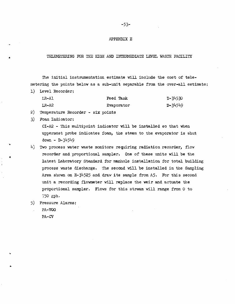
..
-53-
APPENDIX E
TELEMETERING FOR THE HIGH AND INTERMEDIATE LEVEL WASTE FACILITY
The initial instrumentation estimate will include the cost of te1e
metering the pOints below as a sub-unit separable from the over-all estimate:
1) Level Recorder:
LR-A1 Feed Tank
LR-A2 Evaporator
2) Temperature Recorder - six points
3) Foam Indicator:
CI-A2 - This multipoint indicator will be installed so that when
uppermost probe indicates foam, the steam to the evaporator is shut
down - D-34549
4) Two process water waste monitors requiring radiation recorder, flow
recorder and proportional sampler. One of these units will be the
latest Laboratory Standard for manhole installation for total building
process waste discharge. The second will be installed in the Sampling
Area shown on E-34525 and draw its sample from A5. For this second
uni t a recording flowmeter will replace the weir and actuate the
proportional sampler. Flows for this stream will range from 0 to
750 gph.
5) Pressure Alarms:
PA-VOG
PA-CV

•
..
1-3· 4.
5-6. 7· 8.
-54-
Distribution
DTIE, AEC M. J. Skinner Central Research Library Document Reference Section F. E. Harrington