design for a grassed waterway - ideals
TRANSCRIPT

Q.630.7
It6c
no. 1225
cop. 5

• *-

NOTICE: Return or renew all Library Materials! The Minimum Fee for
each Lost Book is $50.00.
The person charging this material is responsible for
its return to the library from which it was withdrawnon or before the Latest Date stamped below.
Theft, mutilation, and underlining of books are reasons for discipli-
nary action and may result in dismissal from the University.
To renew call Telephone Center, 333-8400
UNIVERSITY OF ILLINOIS LIBRARY AT URBANA-CHAMPAIGN
mi*m999»1«
M 8 2(100
UNIVERSITY OFILLINOIS LIBRARY
AT UR3ANA CHAMPAIGNAGRICULTURE
L161—O-1096

Digitized by the Internet Archive
in 2011 with funding from
University of Illinois Urbana-Champaign
http://www.archive.org/details/designforgrassed1225stal

**$+*v*<$
X̂^i
DESIGN FOR A^«
GRASSED WATERWAY
&
£4?
* §7
S7 '»»*

Acknowledgments
The work described in this publication was carried out by researchers
and engineers from the College of Agriculture, University of Illinois at
Urbana-Champaign (UIUC), and the Soil Conservation Service, United
States Department of Agriculture. We are grateful to Roger R. Yoerger,
Head, UIUC Department of Agricultural Engineering, for initiating the
project and to Carroll J. W. Drablos, Professor of Soil and Water Exten-
sion, for his valuable advice.
Personnel of the Soil Conservation Service in state and local offices in
Illinois were most helpful, especially Jeff Healy, Agricultural Engineer at
the Champaign office.
We wish to thank William O. Ree, retired Hydraulic Engineer, Agricul-
tural Research Service, and former Director, Outdoor Hydraulic Labora-
tory at Stillwater, Oklahoma, for his advice.
Authors
John B. Stall, Visiting Associate Professor (1981), Department of Agricultural
Engineering, University of Illinois at Urbana-Champaign
Walter D. Lembke, Professor, Department of Agricultural Engineering,
University of Illinois at Urbana-Champaign
Michael C. Schendel, State Conservation Engineer, Soil Conservation
Service
Dale H. Vanderholm, Professor, Department of Agricultural Engineering,
University of Illinois at Urbana-Champaign, and Assistant Director, Ag-ricultural Experiment Station
Don W. Graffis, Professor, Department of Agronomy, University of Illinois
at Urbana-Champaign

^5?\ate ^X(109**0
CONTENTS
Introduction 1
Applicability 1
Requirements 2
Assistance 2
Sequence of Construction 2
Hydrologic Design 3
Rainfall 3
Hydrologic Soil Group 3
Curve Number 3
Watershed Slope 3
Peak Flow 6
Shape and Dimension 8General Layout 8
Drainage Area 8
Shape 8
Flow Velocity 8
Capacity 8
Waterway Design 8
Subsurface Drainage 9
Construction , 12Methods 12
Establishment of Grass 13Importance 13
Seedbed 13
Seed Mixture 13
Time of Year 15
Temporary Cover 15
Design Example 16Problem 16
Step-by-Step Solution 16
Design by Use of Equations 17Need 17
Hydraulic Equations to Be Used 17
Special Problem 17
Maintenance 18Repair 18
Double Channeling from Improper Plowing 18
Double Channeling from Waterway Sedimentation 19
Mowing 19
Herbicides 19
Related Ideas 20Livestock Waste Disposal 20Sediment Filters 20Design Using Tractive Force 20
References 21

Tables
1. Hydrologic Soil Groups for Illinois 4
2. Runoff Curve Numbers 6
3. Parabolic Channels: Width-Depth Ratios
and Resulting Side Slopes 8
4. Allowable Velocities for Grassed Waterways 8
5. Design Table for Parabolic Grassed Waterways 10
6. Grass Seeding Mixtures Suitable Throughout Illinois 12
7. Fertilizers for Establishing Grass 13
8. Planting Dates for Grass in Illinois 15
9. Temporary Cover for a Waterway Completed in Midsummer 15
10. Calculations for Trial-and-Error Design of Special
Problem Example by Use of Equations 16
Figures
1. The 24-hour Rainfall for Illinois for a 10-Year Return Period 3
2. Watersheds with a Flat Slope 6
3. Watersheds with a Moderate Slope 7
4. Watersheds with a Steep Slope 7
5. Configuration of a Parabolic Waterway 9
6. Roughness Factor for the Manning Equation 9
7. Minimum Spacing for a Tile Drain Beneath a Grassed Waterway 12
8. Plant Suitability Zones of Illinois 14
9. Destruction of Grassed Waterway by Sedimentation 18

INTRODUCTION
Most farm plans for soil and
water conservation must, to be ef-
fective, include grassed waterways
as part of their design. The wide,
shallow, sod-lined channels of
these waterways safely dispose of
surface water from heavy rains and
prevent the formation of gullies.
Wherever surface runoff water
from more than a few acres col-
lects, a gully often forms. A grassed
waterway is needed to prevent the
resulting erosion.
Grassed waterways can makefarming more convenient. If de-
signed and constructed properly,
they can be crossed easily with
farm equipment. Possible damageto equipment taken across a gully
can thus be avoided.
Land used for waterways is not
wasted. The success of the total
soil and water conservation pro-
gram on the farm depends on the
proper removal of surface runoff
water through these waterways.
The area needed for waterways
should therefore be used for its in-
tended purpose. The production
of forage or the use of the land as
a wildlife habitat should be sec-
ondary to the continued, proper
functioning of the waterway as a
means of carrying runoff and pre-
venting erosion.
When making a decision to build
a grassed waterway, the landowner
should first compute the cost and
then select the best time of year
for construction. In Illinois the best
time is usually midsummer: small
grains can be grown earlier, and
the waterway constructed after the
grain is harvested. Grasses can be
seeded right after construction.
During the decade from 1970 to
1980, about 800 miles of grassed
waterways were built on Illinois
farms each year, that is, about 8
miles of waterway per year for
every county. It is hoped that more
grassed waterways will be con-
structed in the next decade.
This circular has been written to
provide up-to-date, easy-to-use in-
formation on the design, construc-
tion, and maintenance of grassed
waterways. The publication is in-
tended for use by land improve-
ment contractors, conservation
technicians, and engineers. Theprocedures given cover the range
of conditions found in Illinois. Themajor publication that has been
used for three decades to design
grassed waterways is the Handbookof channel design for soil and water
conservation (SCS-TP-61), published
and revised by the Soil Conserva-
tion Service in 1954. Current text-
books, such as that by Schwab et
al. (1981), provide design proce-
dures based on the same informa-
tion. The Soil Conservation Ser-
vice's Engineering field manual
(1969) describes procedures that
are also based on this source. Thepresent publication uses the sameprocedures as those in the refer-
ences cited, but the steps have
been greatly simplified. In carrying
out operations on a day-to-day ba-
sis in each Illinois county, techni-
cians will be able to use a pro-
grammable calculator to facilitate
the procedures outlined here.
A design for a grassed waterway
has also been published by the
Northeastern Illinois Soil Erosion
and Sedimentation Control Com-mittee (1981) as part of a set of
procedures for conservation sys-
tems. The material is presented in
a "how-to-do-it" handbook.
Applicability
A grassed waterway is intended
to convey water without eroding
the soil. It is therefore important
that an overland flow regime be
maintained and that the water be

prevented from becoming channel-
ized. Even small irregularities in the
soil surface will disrupt the
smooth, even flow of water downthe waterway, directing the water
into a small, concentrated channel.
The flow velocity will then becomevery high in this small channel and
lead to erosion.
Grassed waterways are used for
the following purposes:
• to drain terraces or diversions
• to dispose of water collected
in road ditches
• to stabilize a natural draw that
is eroding
• to stabilize a natural draw to
which additional runoff water
is being added by contours or
terraces
It is not considered a desirable
conservation practice to modify an
existing natural watercourse if it is
currently carrying water and if the
channel is not eroding. Such a
draw might contain a meandering,
noneroding channel vegetated
with brush and trees that, in addi-
tion to holding the soil in place,
provide a valuable habitat for quails,
rabbits, pheasants, meadowlarks,
cardinals, and other desirable
wildlife.
RequirementsTo allow construction of a
grassed waterway, an area must
have enough soil to establish and
maintain a stand of grass. A stable
outlet is also essential. If a stable
natural outlet is not available, then
a structure is necessary. In addition,
tile drainage may be required be-
neath the waterway.
then be contacted about a specific
conservation plan. The district con-
servationist of the Soil Conserva-
tion Service can provide technical
assistance for developing and im-
plementing a conservation plan
that incorporates the waterways
into a total resource managementsystem. Information about cost-
share assistance can be obtained
from the county office of the Agri-
cultural Stabilization and Conserva-
tion Service.
Sequence of Construction
A grassed waterway should be
built as a part of a total conserva-
tion program. If land treatment
measures are needed to control
soil losses on the land draining into
the grassed waterway, then these
measures should be completed be-
fore the waterway is built. Other-
wise the waterway will be damagedand may require excessive mainte-
nance and reconstruction.
If terraces are to be built to con-
trol upland erosion, then the
grassed waterway may be used as
an outlet for the water collected
by the terrace system. In this case
the grassed waterway should be
built first so that when the terraces
are built, the outlet will already be
available.
Assistance
The county Extension adviser can
give advice on the general applica-
bility of the practice to a particular
farm situation. The county soil andwater conservation district can
HYDROLOGIC DESIGN
'4.6
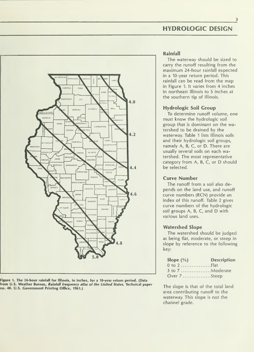
Figure 1. The 24-hour rainfall for Illinois, in inches, for a 10-year return period. (Datafrom U.S. Weather Bureau, Rainfall frequency atlas of the United States. Technical paperno. 40. U.S. Government Printing Office, 1961.)
Rainfall
The waterway should be sized to
carry the runoff resulting from the
maximum 24-hour rainfall expected
in a 10-year return period. This
rainfall can be read from the mapin Figure 1. It varies from 4 inches
in northeast Illinois to 5 inches at
the southern tip of Illinois.
Hydrologic Soil GroupTo determine runoff volume, one
must know the hydrologic soil
group that is dominant on the wa-
tershed to be drained by the
waterway. Table 1 lists Illinois soils
and their hydrologic soil groups,
namely A, B, C, or D. There are
usually several soils on each wa-
tershed. The most representative
category from A, B, C, or D should
be selected.
Curve NumberThe runoff from a soil also de-
pends on the land use, and runoff
curve numbers (RCN) provide an
index of this runoff. Table 2 gives
curve numbers of the hydrologic
soil groups A, B, C, and D with
various land uses.
Watershed Slope
The watershed should be judged
as being flat, moderate, or steep in
slope by reference to the following
key:
Slope (%) Description
to 2 Flat
3 to 7 ModerateOver 7 Steep
The slope is that of the total land
area contributing runoff to the
waterway. This slope is not the
channel grade.

Table 1. Hydro logic Soil Groups for Illinois
Soil series Hydrologic Soil series Hydrologic Soil series Hydrologic
Name Number soil group Name Number soil group Name Number soil group
A Ade 98 A Chute 282 A Ginat 460 DAdrian 777 A/D Cisne 2 D Gorham 162 B/DAholt 670 D Clarence 147 D Gosport 551 CAlford 308 B Clarksdale 257 C Goss 606 B
Allison 306 B Clarksville 471 B Granby 513 A/DAlvin 131 B Clinton 18 B Grantfork DAmbraw 302 B/D Coatsburg 660 D Grantsburg 301 CAndres 293 B Coffeen 428 B Grays 698 B
Aptakisic 365 B Colo 402 B/D Grellton 780 B
Arenzville 78 B Colp 122 C Griswold 363 B
Argyle 227 B Comfrey 776 B/DArmiesburg 596 B Corwin 492 B H Hamburg 30 B
Ashdale 411 B Cowden 112 D Harco 484 B
Ashkum 232 B/D Coyne 764 B Harpster 67 B/DAssumption 259 B Creal 337 C Harrison 127 B
Atkinson 661 B Hartsburg 244 B/DAtlas 7 D D Dakota 379 B Harvard 344 B
Atterberry 61 B — Dana 56 B Hayfield 771 B
Ava 14 C Darmstadt 620 D Haymond 331 B
Ayr 204 B Darroch 740 C Haynie 394 B
Darwin 71 D Hennepin 25 B
B Backbone 768 B Del Rey 192 C Herbert 62 B
Banlic 787 C Denny 45 D Herrick 46 B
Barrington 443 B Denrock 262 D Hesch 390 B
Batavia 105 B Derinda 417 C Hickory 8 CBaxter 599 B Dickinson 87 B High Gap 556 CBaylis 472 B Disco 266 B Hitt 506 B
Beardstown 188 C Dodge 24 B Homer 326 CBeasley 691 C Dodgeville 40 B Hononegah 354 ABeaucoup 70 B/D Dorchester 239 B Hoopeston 172 B
Bedford 598 C Douglas 128 B Hosmer 214 CBeecher 298 C Dowagiac 346 B Houghton 103 A/DBelknap 382 C Downs 386 B Hoyleton 3 CBerks 955 & 986 C Dresden 325 B Huey 120 DBillett 332 B — Drummer 152 B/D Huntington 600 B
Binghampton 355 B Drury 75 B Huntsville 77 B
Birds 334 C/D Dubuque 29 B Hurst 338 DBirkbeck 233 B Dunbarton 505 CBlackoar 603 B/D Du Page 321 B 1 lona 307 B
Blair 5 C Dupo 180 C Ipava 43 B
Bloomfield 53 B Durand 416 B Iva 454 CBlount 23 CBluford 13 C E Ebbert 48 C/D J Jacob 85 DBodine 471 B Edgington 272 B/D Jasper 440 B
Bold 35 B Edinburg 249 C Joliet 314 DBonfield 493 B Edmund 769 D Joslin 763 B
Bonnie 108 C/D "" Elburn 198 B Joy 275 B
Booker 457 D Elco 119 B Jules 28 B
Boone 397 A El Dara 264 B Juneau 782 B
Bowdre 589 C Eleroy 547 B
Bowes 792 B Eleva 761 B K Kane 343 B
Boyer 706 B Elkhart 567 B Kankakee 494 B
Brandon 956 B Elliott 146 C Karnak 426 DBrenton 149 B Elsah 475 B Keller 470 CBroadwell 684 B Emma 469 C Keltner 546 B
Brooklyn 136 C Kendall 242 B
Bryce 235 D F Faxon 516 B/D Keomah 17 CBurkhardt 961 B Fayette 280 B Kernan 554 CBurnside 427 B Fieldon 380 B/D Kidder 361 B
Fincastle 496 C Knight 191 B/DC Cairo 590 D Fishhook 6 D
Calamine 746 D Flagg 419 B L La Hogue 102 B
Calco 400 B/D Flagler 783 B Lamont 175 B— Camden 134 B
—Flanagan 154 B Landes 304 B
Canisteo 347 C/D Fox 327 B La Rose 60 B
Cape 422 D Frankfort 320 C Lawler 647 B
Carmi 286 B Friesland 781 B Lawndale 683 B
Casco 323 B Frondorf 781 B Lawson 451 C— Catlin 171 B Fults 591 D Lax 628 C
Channahon 315 D Lena 210 A/DChatsworth 241 D G Gale 413 B Lenzburg 871 B
Chauncey 287 C Genesee 431 B Lisbon 59 B
Chelsea 779 A Gilford 201 B/D Littleton 81 B

Table 1 — continued
Soil series
Name NumberHydrologicsoil group
Soil series
Name NumberHydrologic
soil group
Soil series Hvdrolosic
Name Number soil group
LomaxLoran
Lorenzo
M MarineMarissa
MarkhamMarklandMarseilles
MarshanMartinsville
Martinton
MassbachMathertonMaumeeMcFainMcGaryMcHenryMedwayMetea— MiamiMiddletownMilford
Millbrook
Millington
Millsdale
MokenaMonaMoneeMontgomeryMontmorenciMorleyMoroccoMt. Carroll
MundeleinMurenMuscatine
MuskegoMuskingumMyrtle
N NachusaNameokiNappaneeNasset
NegleyNeotomaNewberryNew Glarus
Niota
Oakville
OckleyOconeeOctagonOdell
OgleOkawOnargaOnecoOrioOrionOtter
Palms
Palsgrove
Pana
PapineauParke
Parkville
Parr
Patton
Pecatonica
265
572
318
517
176
531
467549
772
570
189
753
342
89
248
173
310
682
205
27
685
69
219
82
317
295
448
229
465
57
194
501
268
442
453
41
621
425
414
649
592
228
731
585
976 & 977
217
928 & 561
261
741
387
113
656
490412
84
150
752
200
41576
100
429
256
42
15
619
221
142
21
B
B
B
CCCCB
B/DB
CB
B
A/DCCB
B
B
B
B
B/DB
B/DB/DCB
DDB
CB
B
B
B
B
A/DCB
B
DDB
B
B
CB
D
AB
CB
B
B
DB
B
B/DCB/D
A/DB
B
CB
CB
B/DB
— Pella
PeotonePetrolia
Piasa
Pike
Pillot
Piopolis
Plainfield
Piano
Plattville
Port ByronPrairieville
Proctor
R RacoonRaddleRadford
Rantoul
Rapatee— Raub
ReddickReesville
Richview
Ridgeville
Ridott
Riley
RingwoodRiponRitchey
RobbsRobyRocktonRodmanRomeoRoss
RoweRozetta
RuarkRushRushville
Russell
Rutland
S Sabina
Sable
Saffell
Sarpy
SaudeSawmill
SaybrookSaylesville
Schapville
Sciotoville
Seaton
SelmaSexton
ShadelandSharon
Shiloh
Shoals
Shullsburg— Sidell
SognSparta
St. Charles
St. Clair
Starks
Stockland
Stonelick
Stoy
Strawn
Streator
Stronghurst
153
330
288
474
583
159
420
54
199
240
277
650
148
109
43074
238
872
481
594
723
4
151
743
452
297
324
311
335
184
503
93
316
73
230
279
178
791
16
322
375
236
68
956
92
744107
145
370
418
462
274
125
208
555
72
138
424745
55
504
88
243
560
132
155
665
164
224
435
278
B/DB/DB/DDB
B
C/DAB
B
B
B
B
C/DB
B
DDCB/DCCB
CB
B
B
DDCB
ADB
DB
B/DB
DB
C
CB/DB
AB
B/DB
CCCB
B/DC/DCB
B/DCCB
DAB
DCB
B
CB
B/DB
SunburySwygert
Sylvan
Symerton
T Tallula
TamaTamalcoTell
Terril
ThebesThorpTice
Timula
Titus
TorontoTraer
TrempealeauTroxel
U UniontownUrsa
V VanpettenVarna
VelmaVirden
Virgil
W WabashWagnerWakelandWallkill
WareWarsawWashtenawWatsekaWaucondaWaukeeWaukeganWaupecanWeaWeinbachWeir
Wellston
WenonaWesleyWestland
WestmoreWestville
WhalenWheelingWhitakerWhitsonWill
WingateWinnebagoWoodbineWorthenWynoose
\, Xenia
Zanesville
ZippZookZurich
Zwingle
234
91
19
294
34
36
581
565
587
212
206
284
271
404
353
633
765
197
482605
357
223
250
50
104
83
26
333
292
456
290
296
49
697
727564
369
398
461
165
339
388
141
300
940
22
509
463
571
116
329
348
72841037
12
291
340
524
504
696
576
B
CB
B
B
B
DB
B
B
C/DB
B
B/DCB/DB
B
B
C
B
CB
B/DB
DDB/DDB
B
C/DB
B
B
B
B
B
CDB
CB
B/DCB
B
B
CDB/DB
B
B
B
D
B
CC/DC/DB
D
Note: Two soil groups, such as B/D, indicate
that the hydrologic soil group is B for a
drained condition and D for an undrained
condition.

Peak Flow
The graphs in Figures 2, 3, and 4
show the peak flow in cubic feet
per second (cfs) to be expected
from watersheds of 5 to 200 acres,
for rainfalls from 4 to 5 inches, and
for curve numbers from 60 to 90.
Figure 2 pertains to watersheds
with a flat slope; Figure 3 to wa-
tersheds with a moderate slope;
and Figure 4 to watersheds with a
steep slope. By reading the appro-
priate graph, one can determine
the peak flow. This is the flow rate
(cfs) that the grassed waterway
must be designed to carry.
Table 2. Runoff Curve Numbers
DescriptionA
Hydrologic
B
Soil C roupC D
Cultivated
without conservation treatment 72 81 88 91
with conservation treatment 62 71 78 81
Pasture or rangepoor condition 68 79 86 89
good condition 39 61 74 80
Meadow 30 58 71 78
Woods or Forest
thin stand, poor cover, no mulch 45 66 77 83
good cover 25 55 70 77
Farmsteads 59 74 82 86
Roads 74 84 90 92
Note: The curve numbersand 4. Use CN 60 for these
n bold type are
conditions.
less than the values given in Figures 2, 3,
1,000
oz
uLU<Si
OSLUa.
"- 100u
U
8*
<
10
curv e ni rip »ry
R tiiif ill, inc! les
*\ y'y'.
_^^ v Vp/ V^5
4^
1,000
90
80
70
60
100
10
Ci irue lumbi T
1,1 infall, in<:hes
^r
"t^r/̂^
•|54>^
Iv*t ^
fy--j^^
85
75
65
5 10 100 200 5 10
WATERSHED, ACRES
Figure 2. Watersheds with a flat slope.
100 200

1,000
100
10
<^ur ve mml ^<:r
F ai ifall, iriche
7AjV^j' *
*** Sk 44 4
**
i
1,000
90
80
70
60
100
10
Cu rvu it ji nber
F <i ifall, inche »
j&
jS S 4\
.^
t&/£* $y^^
^yS
5 10 100 200 5 10
WATERSHED, ACRES
Figure 3. Watersheds with a moderate slope.
85
75
65
100 200
10 100 200 5 10
WATERSHED, ACRES
Figure 4. Watersheds with a steep slope.
1,000r 1,000
90
80
70
60 100
10
5
t| ur ve i li ii ^"ber (lu "V2 nu ribe •
\u ifall, in< hes^ I til infall, in< :hes
IUU 1 .
Vf. SsX4y s s
/ y^ .
/ A^j s*s&1' 3^
1ft -
/ 4/ f*/'*/
/f5-
85
75
65
100 200

SHAPE AND DIMENSION
General Layout
A natural drainageway should be
used if possible. Other desirable
features are an existing stable out-
let for the drainageway; soil and
moisture conditions already favor-
able for growing grass; and enoughdepth in the drainageway to allow
for outlets from terraces, diver-
sions, or crop rows at the grade of
the constructed waterway without
necessitating structures.
Table 3. ParabolDepth 1
Side Sic
c Channels: Width-ratios and Resulting•pes*
Width-Depthratio, T/d
Side
edgei slope at
of channel
Crossable Horizontal
(for 1 vertical)
48 12
44 11
40 10
36 9
32 8
29 7
24 6
Not crossable
20 5
16 4
12 3
8 2
4 1
* The equation for this relationship is: side
slope = T/4d
Table 4. Allowable Velocities for
Grassed Waterways
Velocity
(feet per second)Grass
(condition)
Maximum 3
4
5
Minimum 1.5
poornormalspecial cases of
dense sod
velocity required
to prevent
sediment fromdepositing
Drainage AreaWalk the boundary of the wa-
tershed and sketch it on a map or
aerial photo, then measure the
area. The size of the waterway de-
pends on the peak flow, which in
turn is proportional to the drain-
age area. Be sure to include the
drainage area that may lie across
the fence and belong to another
landowner.
A field survey should be madealong the course of the proposed
waterway. Make a profile of the
existing natural channel including
cross sections. The waterway
should then be divided into
reaches having an approximately
uniform slope and cross section.
This will allow the waterway to be
constructed in such a way that a
minimum amount of earth will be
moved. A significant break in slope
makes a point of division betweenreaches. The entrance point of a
tributary — where the watershed is
significantly increased — is also a
natural point of division between
reaches. By using the drainage area
for each reach and calculating the
peak flow, one can design the
waterway according to the reaches.
During construction, the slope and
shape of each reach is gradually
adjusted to that of the next reach.
ShapeThe cross-sectional shape of the
waterway should be parabolic — a
shape in nature generally found to
be suitable for a stable channel and
one in which small flows are least
likely to meander. The shape allows
easy crossing with farm equipmentif the side slopes at the edge of
the channel are gentler than 5 to
1, as indicated in Table 3. Shown in
Figure 5 is a sketch of the para-
bolic shape. T is the top width in
feet and d is the maximum depthin feet occurring at the centerline.
The shape is easy to visualize and
build because at a width of 0.5 Tthe depth is 0.75 d, and at a width
of 0.7 T the depth is 0.5 d.
Flow Velocity
Because the erosion resistance of
soil increases with dense vegeta-
tion, the maximum allowable flow
velocity in feet per second (fps) is
related to the thickness or density
of the grass that covers the chan-
nel bed. Table 4 shows allowable
velocities. In determining the
width and depth of the channel
required to carry the peak flow, it
is necessary, as will be shown, to
manipulate the velocity and flow
area so that the channel will be
large enough, stable, and crossable
with farm implements.
Capacity
Different grasses vary in their re-
sistance to the flow of water. Thestems and leaves of the grass bend
and oscillate under the influence
of the velocity and the depth of
flow. This flow can be predicted by
the Manning equation, which is
given and explained later in this
publication.
Flow resistance is expressed in
the Manning equation as the
roughness coefficient or n value.
Research published by the Soil
Conservation Service (1954) relates
the n value in the Manning equa-
tion to the product, VR; that is,
the velocity, V, multiplied by the
hydraulic radius, R. These factors
are related by a family of curves
having different values of retar-
dance. The curves are shown in
Figure 6. The retardance categories
of A, B, C, D, and E are expressed
for various grasses and grass man-
agement conditions.
Waterway Design
Table 5 is presented here as a
design table applicable to all gen-
eral conditions in Illinois. Its use al-
lows the selection of a top width,

T, and a depth, d, for a parabolic
channel that will carry the flow re-
quired. Table 5 gives values of T
and d that have been calculated
using the Manning equation with
two selected values of retardance,
B and D, as described below.
For the purpose of checking the
stability of the channel, a retar-
dance class of D has been used to
calculate the maximum velocity
normally expected to occur in that
channel. The extreme left column
of Table 5 gives values for the rate
of flow, Q, in cubic feet per sec-
ond. The top width, T, and the
depth, d, are given for each value
of channel slope, S, of a parabolic
channel that will carry the flow, Q,given in the left column. At the
top of each column is the value of
V 1; which is the maximum flow ve-
locity that will occur in this chan-
nel for a retardance of D. Note
that Table 4 specifies a maximumallowable velocity of 4 feet per
second under normal conditions.
Retardance D is considered appro-
priate for almost all grass mixtures
recommended for use in Illinois
when the waterway is mowed reg-
ularly and the grass is generally less
than 6 inches high.
An additional calculation has
been made for each entry in Table
5 so that the capacity of the chan-
nel can be checked. The recom-
mended grass mixtures have a
much higher resistance to flow
when the grass is unmowed. Grass
may then be 12 to 18 inches high,
at which time retardance B is ap-
propriate for use. For each flow
rate in Table 5, a value of V 2 is
shown, which is always smaller
than Vv The value of V 2 is the av-
erage flow velocity in the given
channel as calculated by the Man-ning equation using retardance B.
The channel must be, and is, able
to carry the flow when the lower
velocity, V 2 , occurs. (See Table 6.)
T
^S. ^0.50d" T
-o
n0.75d
++*^ T ^^0
^'^
0.5T
0.7T
^
^
Figure 5. Configuration of a parabolic waterway.
Subsurface Drainage
A drainageway that is normally
wet should be tiled before a goodgrassed waterway can be estab-
lished. The design of the waterway
should therefore include the tile
drainage. As shown in Figure 7, the
tile line should be at least 2 feet
lower than the center of the con-
structed waterway and at least
one-third the width of the water-
way as measured from the center-
0.5
0.4
0.3
line of the waterway. Tiling pro-
vides adequate drainage and also
reduces erosion of the backfill ma-terials in the tile drain. The size of
the tile must be such that the tiling
not only drains the waterway chan-
nel effectively, but also fits into the
entire local tile drainage system.
Such a tile line, located adjacent to
a waterway, often acts as a tile
main, serving other upstream tile
lines.
e
bzzz<2
0.2
0.1
0.08
0.06
0.05
0.04
0.03
0.02
A
S^B
C
[ I
E
0.1 0.2 0.3 0.40.50.6 0.8 1 2 3 4 5 6 8 10 20
VR, PRODUCT OF VELOCITY AND HYDRAULIC RADIUS
Figure 6. Roughness factor, n, for the Manning equation as related to velocity, V, hy-
draulic radius, R, and retardance. (Reprinted from U.S. Soil Conservation Service, Hand-book of channel design for soil and water conservation, SCS-TP-61, 1966.)

10
Table 5. Design Table for Parabolic Grassed Waterways
Slope, %V„ fps
Q, cfs
0.25
V, 2.5
T d
0.50
V, 2.5
d
0.75
V, 3.0
d
1.0
V, 3.0
T d
1.25
V, 3.0
T d
1.50
V, 3.0
T d V 2
15
T i
15
20
25
30
35
40
45
50
55
60
65
70
75
80
90
100
110
120
130
140
150
160
170
180
190
200
220
240
260
280
300
11 2.6 1.4
12 2.5 1.5
14 2.5 1.5
12 3.6 1.4 16 2.5 1.5
13 3.5 1.4 18 2.4 1.5
15 3.4 1.5 20 2.4 1.5
16 3.4 1.5 22 2.4 1.6
18 3.4 1.5 24 2.4 1.6
19 3.3 1.6 26 2.4 1.6
20 3.3 1.6 28 2.4 1.6
22 3.3 1.6 30 2.4 1.6
23 3.3 1.6 32 2.4 1.6
26 3.3 1.6 36 2.4 1.6
29
31
35
37
40
43
45
48
51
54
59
62
68
73
79
84
3.2
3.2
3.2
3.2
3.2
3.2
3.2
3.2
3.2
3.2
3.2
3.2
3.2
3.2
3.2
3.2
1.6
1.6
1.6
1.6
1.7
1.7
1.7
1.7
1.7
1.7
1.7
1.7
1.7
1.7
1.7
1.7
40
44
4852
55
59
63
6771
75
79
87
94
102
110
118
2.3
2.3
2.3
2.3
2.3
2.3
2.3
2.3
2.3
2.3
2.3
2.3
2.3
2.3
2.3
2.3
1.6
1.6
1.6
1.6
1.6
1.6
1.6
1.6
1.6
1.6
1.6
1.6
1.6
1.6
1.6
1.6
10
11
13
15
17
18
20
22
24
25
27
29
33
36
4043
47
50
54
57
61
65
6872
79
86
93
100
109
2.3
2.3
2.2
2.1
2.1
2.1
2.1
2.1
2.1
2.1
2.1
2.1
2.1
2.1
2.1
2.1
2.1
2.1
2.1
2.1
2.1
2.1
2.1
2.1
1.7
1.8
1.8
2.2 1.8
2.2 1.9
2.2 1.9
2.2 1.9
2.2 1.9
1.9
1.9
1.9
1.9
1.9
1.9
1.9
2.0
2.0
2.0
2.0
2.0
2.0
2.0
2.0
2.0
2.0
2.0
2.0
2.0
2.0
9
11
13
15
17
19
21
23
25
28
30
32
34
38
42
46
5054
59
63
6771
75
79
83
91
99108
114
124
2.0
2.0
1.9
1.9
1.9
1.9
1.9
1.9
1.9
1.9
1.9
1.9
1.9
1.9
1.9
1.9
1.9
1.9
1.9
1.9
1.9
1.9
1.9
1.9
1.9
1.9
1.9
1.9
1.9
1.9
1.6
1.7
1.8
1.8
1.8
1.8
1.9
1.9
1.9
1.9
1.9
1.9
1.9
1.9
1.9
1.9
1.9
1.9
1.9
1.9
1.9
1.9
1.9
1.9
1.9
1.9
1.9
1.9
1.9
1.9
8
10
13
15
17
20
22
25
27
29
32
34
37
39
44
49
53
58
63
68
72
77
82
87
91
96
1.9
1.8
1.8
1.7
1.7
1.7
1.7
1.7
1.7
1.7
1.7
1.7
1.7
1.7
1.7
1.7
1.7
1.7
1.7
1.7
1.7
1.7
1.7
1.7
1.7
1.7
106 1.7
115 1.7
124 1.7
134 1.7
143 1.7
9
12
15
17
20
23
26
29
32
34
37
40
43
4651
57
62
6873
79
85
90
96
101
107
112
123
134
145
156
167
1.7
1.6
1.6
1.6
1.6
1.5
1.5
1.5
1.5
1.5
1.5
1.5
1.5
1.5
1.5
1.5
1.5
1.5
1.5
1.5
1.5
1.5
1.6
1.6
1.6
1.7
1.6 1.7
1.6 1.7
1.6 1.7
1.6 1.7
1.5 1.7
1.7
1.7
1.7
1.7
1.7
1.7
1.7
1.7
1.7
1.7
1.7
1.7
1.7
1.7
1.7
1.7
7
9
11
14
16
18
20
22
24
26
2831
33
35
39
43
48
52
56
60
65
94
103
111
120
128
1.5 1.7 69 1.i
1.5 1.7 73 1..
1.5 1.7 77 1.!
1.5 1.7 82 1.
1.5 1.7 86 1.
1.
1.
1.
1.(
I.I
Source: Soil Conservation Service, Engineering field manual, 1969.
Note: Given is the top width, T, in feet; the maximum depth, d, in feet; the range of slope, S, percent; and the range of flow, Q, in cubic
feet per second. Given also is the maximum velocity, V 1( that will occur in the waterway, in feet per second, calculated for a retardance of
D; and the minimum velocity, V 2 , that will occur, in feet per second, calculated for a retardance of B.
Entries in the table outside the shaded section will have side slopes at the edge that are greater than 1, vertical, and 6, horizontal. See
Table 3. These slopes are not readily crossable with farm machinery. If crossability is desired, a different T and d should be calculated on the
basis of the equations provided.

11
2.0
V, 3.5
T d
3.0
V, 3.5
T d
4.0
V, 4.0
T d V 2
5.0
Vt 4.0
T d V2
6.0
V, 4.0
T d
8.0
V, 4.0
T d
10.0
V, 4.0
T d V2
1 1.8
1 2.0
8
10
1.6
1.5
1.8
1.9
10
14
1.2
1.2
1.7
1.8
9 1
12 1
2 2.1
2 2.1
11
14
1.0
1.0
2.0
2.0
12
16
1.0
1.0
2.0
2.0
14 0.8 1.9
18 0.8 1.9
1 2.0
1 2.1
1 2.1
U 2.1
13
15
18
20
1.5
1.5
1.5
1.5
2.0
2.0
2.0
2.0
17
20
1.2
1.2
1.8
1.8
15 1
18 1
21 1
2 2.1
1 2.1
1 2.1
18 1.0 2.1 19 1.0 2.0 23
27
32
36
0.8
0.8
0.8
0.8
2.0
21
24
28
1.0
1.0
1.0
2.1
2.1
2.1
24
27
31
1.0
1.0
1.0
2.0
2.0
2.0
2.0
24
27
1.2
1.2
1.8
1.8
2.0
24 1 1 2.2 2.0
1. 2.1 23 1.5 2.0 30 1.2 1.8 27 1 1 2.2 31 1.0 2.1 35 1.0 2.0 41 0.8 2.0
I, 2.2 25 1.5 2.0 34 1.2 1.8 30 1 1 2.2 35 1.0 2.1 38 1.0 2.0 45 0.8 2.0
1. 2.2
1. 2.2
28 1.5 2.0 37
401.2
1.2
1.8
1.9
33 1
36 1
1 2.2
1 2.2
3841
1.0
1.0
2.1
2.1
42
461.0
1.0
2.0
2.0
49
54
0.8
0.8
2.0
30 1.5 2.0 2.0
1.| 2.2 33 1.5 2.0 43 1.2 1.9 39 1 1 2.2 45 1.0 2.1 50 1.0 2.0 58 0.8 2.0
I.I 2.2 35 1.5 2.1 47 1.2 1.9 42 1 1 2.2 48 1.0 2.1 53 1.0 2.1 62 0.8 2.0
1.1 2.2 37 1.5 2.1 50 1.2 1.9 45 1 1 2.2 51 1.0 2.1 57 1.0 2.1 67 0.8 2.0
lj 2.2 40 1_5 2.1 53 1.2 1.9 48 1 1 2.2 55 1.0 2.1 61 1.0 2.1 71 0.8 2.0
1( 2.2 45 1.5 2.1 60 1.2 1.9 54 1. 1 2.2 62 1.0 2.1 68 1.0 2.1 80 0.8 2.0
It 2.2 50 1.5 2.1 66 1.2 1.9 60 1. 1 2.2 68 1.0 2.1 76 1.0 2.1 88 0.8 2.0
1. 2.2 55 1.5 2.1 73 1.2 1.9 65 1. 1 2.2 75 1.0 2.1 83 1.0 2.1 97 0.8 2.0
I 2.2 59 1.5 2.1 79 1.2 1.9 71 1. 1 2.2 81 1.0 2.2 90 1.0 2.1 105 0.8 2.0
1.6 2.2 64 1.5 2.1 86 1.2 1.9 77 1. 1 2.2 88 1.0 2.2 98 1.0 2.1 114 0.8 2.0
li 2.2 69 1.5 2.1 92 1.2 1.9 83 1. 1 2.2 95 1.0 2.2 105 1.0 2.1 122 0.8 2.0
1,1 2.2 74 1.5 2.1 99 1.2 1.9 89 1. 1 2.2 101 1.0 2.2 112 1.0 2.1 131 0.8 2.0
1 2.2 79 1.5 2.1 105 1.2 1.9 94 1. 1 2.2 108 1.0 2.2 119 1.0 2.1 139 0.9 2.0
E 2.2 84 1.5 2.1 111 1.2 1.9 100 1. 1 2.2 114 1.0 2.2 126 1.0 2.1 147 0.9 2.0
IS; 2.2 88 1.5 2.1 118 1.2 1.9 106 1. 1 2.2 121 1.0 2.2 134 1.0 2.1 156 0.9 2.0
li 2.2 93 1.5 2.1 124 1.2 1.9 111 1. 1 2.2 127 1.0 2.2 141 1.0 2.1 164 0.9 2.0
1 2.2 98 1.5 2.1 130 1.2 1.9 117 1. 1 2.2 134 1.0 2.2 148 1.0 2.1 172 0.9 2.0
li 2.2 108 1.5 2.1 143 1.2 1.9 129 1. 1 2.2 147 1.0 2.2 162 1.0 2.1 189 0.9 2.0
li 2.2 117 1.5 2.1 156 1.2 1.9 140 1. 1 2.2 160 1.0 2.2 177 1.0 2.1 206 0.9 2.1
1.6 2.2 127 1.5 2.1 169 1.2 1.9 152 1. 1 2.2 173 1.0 2.2 191 1.0 2.1 222 0.9 2.1
.6 2.2 136 1.5 2.1 181 1.2 1.9 163 1. 1 2.2 186 1.0 2.2 205 1.0 2.1 239 0.9 2.1
.6 2.2 146 1.5 2.1 194 1.2 1.9 174 1. 1 2.2 198 1.0 2.2 219 1.0 2.1 255 0.9 2.1
16
21
26
31
36
41
45
51
56
61
6671
76
81
91
100
110
120
129
139
148
158
167
177
186
195
214233
252270289
0.8
0.8
0.8
0.8
0.8
0.8
0.8
0.8
0.8
0.8
0.8
0.8
0.8
0.8
0.8
0.8
0.8
0.8
0.8
0.8
0.8
0.8
0.8
0.8
0.8
0.8
0.8
0.8
0.8
0.8
0.8
1.9
1.9
1.9
1.9
1.9
1.9
1.9
1.9
1.9
1.9
1.9
1.9
1.9
1.9
2.0
2.0
2.0
2.0
2.0
2.0
2.0
2.0
2.0
2.0
2.0
2.0
2.0
2.0
2.0
2.0
2.0

12
CONSTRUCTION
Figure 7. Minimum spacing for a tile drain beneath a grassed waterway.
Table 6 . Grass Seeding Mixtures Suitable Throughout Illinois
Number Grasses
Rate,
poundsper acre
Wet, all or w ,,
part , . , RetardanceT drained
of year
Recommended mixtures
1 Smooth bromegrassTall fescue
10
20
X X B
2* Smooth bromegrassTimothyRedtop
25
5
2
X B
3 Reed canarygrass
Tall fescue
Redtop
15
10
2
X X B
4 Tall fescue
Redtop20
4
X B
5* Redtop 10 X C
Special purpose mixtures
6* Reed canarygrass
Timothy or redtop20
5
X A
For very wet, swampy conditions
7 Kentucky bluegrass
For urban setting, full sun
40 X C
8 Kentucky bluegrass
Red Fescue5
25
X X B
For urban setting, partly shaded
* In addition to controlling erosion in
cover for some species of desirable wthe waterway,
ildlife.
these three mixtures will also provide
MethodsRemove all brush and rocks
larger than 6 inches in diameter
and bury them elsewhere, not be-
neath the waterway.
Drive centerline stakes to markthe intended waterway. Using off-
set stakes will help maintain
planned grades and aid in checking
construction. If the subsoil in this
region will not support the growth
of grass, remove the topsoil from
the waterway and stockpile it
nearby, out of the way.
Shape the waterway to the de-
sign grade and parabolic cross sec-
tion. Fill the gullies gradually. Pack
the fill to prevent settling in the
future. Be conscious of safety
when operating the equipment. Donot drive too near the edge of a
steep gully. Spread the stockpiled
topsoil evenly over the surface of
the shaped waterway.
Frequently measure the width,
depth, and grade of the waterway to
be sure it complies with the design
These conditions are important:
1. Centerline elevations must be
as planned so that a uniform grade
is maintained.
2. Depth at a distance of one-
fourth of the top width from the
center should change from d to
0.75 d. (See Figure 5.)
3. Edges should be feathered
into the adjacent topography out-
side the design cross section. Thefinal shaping of the waterway sur-
face is critical. The surface must be
smooth because small mounds or
holes will create local flow veloci-
ties that will destroy the waterway
by erosion. All changes in grade
from one reach to the next should
be smooth and gentle.
If a waterway is improperly con-
structed so that it has a nonuni-
form grade or an incorrect cross-
sectional shape, it is likely to be
unstable and to erode rapidly.

13
ESTABLISHMENT OF GRASS
Importance
Probably the single most impor-
tant condition in establishing a
grassed waterway is that the grass
be planted immediately after earth-
moving is completed. If the grass is
not established quickly, the bare
earth of the channel will be
eroded. This erosion will change
the shape of the waterway, de-
stroying its efficiency and often re-
quiring that the waterway be re-
built.
SeedbedAll seedings of grass require a
moist, firm seedbed containing
plenty of available plant food. Be-
gin by testing the soil and applying
the fertilizer and lime as needed to
build up the soil and establish the
grass. (See Table 7.)
The seedbed should be workedto thoroughly incorporate the lime
and fertilizer to a minimum depth
of 3 inches. A small disk and har-
row are practical tools for prepar-
ing the seedbed. Seed with a
double corrugated roller seeder,
pressing the seed into the firm
seedbed to a depth of Va to Vi
inch. Coverage of Y\b to Va inch is
ideal. Seed across the waterway,
not up and down. If a grain drill is
used for seeding, take care to seed
shallow, and definitely seed across
the waterway. The seeded water-
way should be mulched with straw
at the rate of 2,000 pounds per
acre. The straw will help to pre-
vent erosion and to retain mois-
ture, thus ensuring the maximumrate of germination. It will also
help protect the young seedlings
from drying out by providing someshade and reducing excessive loss
of water from the plants by evapo-
transpiration.
The mulch may be anchored by
using mulch netting or by disking
with a dull disk that is set straight.
The disk anchors the mulch by
pushing it into the soil surface.
Disking should be at right angles to
the flow of water in the waterway.
Seed Mixture
There are six grasses that are
well adapted to conditions in Illi-
nois and make desirable vegetative
covers in waterways.
Tall fescue is a moderately win-
ter-hardy grass that makes a goodvegetative cover. It is a bunchgrass, but the leaves "shingle
down" when water flows over
them, thus protecting the soil. It
has been grown successfully in all
parts of the state but is particularly
suited to southern Illinois. In fact it
is superior to other grasses in that
area. Tall fescue grows best on fer-
tile, well-drained soil, but if well
fertilized, it will also flourish on
low-fertility soils and on fine-tex-
tured soils that drain slowly. Seeds
germinate readily and seedlings
grow rapidly, thus establishing a
quick cover. Unfortunately, tall fes-
cue is not a grass that attracts wild-
life.
Smooth bromegrass is a very
winter-hardy, aggressive, sod-form-
ing grass, popular in northern and
central Illinois. When well estab-
lished, it gives good protection to
a waterway channel. Smooth brome-
grass is also desirable because it at-
tracts pheasants for nesting and
Table 7. Fertilizers for Establishing
Grass
Element
Minimumapplication,
pounds per acre
Nitrogen, N
Phosphorus, P
Potassium, K
120 (nitrogen)
120 (P 2O s )
120 (K 20)

14
roosting. It does best on fertile,
well-drained soils. Southern strains
are recommended for use in this
state because they grow more pro-
fusely through the warm months of
summer than do northern strains.
Timothy and redtop are two
grasses well suited to waterway
seedings in all parts of Illinois al-
though they are not as deeprooted as the other three recom-
mended grasses. Although Timothy
is a bunch grass, dense populations
make it a suitable soil-protective
cover. Redtop makes a good turf
quickly and grows under a wide
range of soil and climatic condi-
tions. It does best on fertile soil
but grows fairly well under
droughty conditions, on wet soils,
on moderately acid soils, and on
soils low in fertility. Timothy, like
redtop, has been widely adapted,
but it requires somewhat more fer-
tile soil and does not grow as well
on wet soil or during hot, dry
weather. For secondary reasons,
both timothy and redtop are very
desirable grasses: they attract wild-
life, especially ground-nesting birds.
Reed canarygrass is a long-lived,
sod-forming, very winter-hardy pe-
rennial that produces an excellent
growth in droughty and wet areas.
It is useful in waterways that re-
main too wet and marshy for other
grasses to thrive in. The wet,
marshy waterway has to be pre-
pared and seeded, however, whenthe soil is dry, usually in the late
summer. Reed canarygrass can be
seeded in the same manner as
other grasses. New seed should be
used, as old seed does not germi-
nate well. An alternative method is
to take rootstocks from an estab-
lished stand, chop them, spread
them with a manure spreader, and
disk them into the soil. Be sure to
disk across the channel. Pheasants
and ducks will sometimes nest in
reed canarygrass.
Figure 8. Plant suitability zones of Illinois. These broad zones are based on certain plant-
growth factors including average January-July temperatures, frost-free days, and annual
rainfall. The zones are used as a guide in selecting grasses, legumes, shrubs, trees, andvines for planting. (Reprinted from U.S. Soil Conservation Service, Technical guide for
Illinois, section l-B, plant suitability zone map. Champaign, Illinois, January, 1982.)
&<* KM9"f V*t
fOOfcl Vjag |riy*flVI* W N4T A%.£A$

15
Kentucky bluegrass grows best
on fertile soils in central and
northern Illinois, where it has been
used extensively in waterways. It is
not as deep rooted as the other
grasses already mentioned and
therefore is not as desirable. Pres-
ent practices omit bluegrass from
the seeding mixture. On fertile
soils it will naturally invade stands
of other grasses, especially if they
are closely mowed or thinned.
Kentucky bluegrass is attractive to
wildlife.
Seed mixtures of the grasses
mentioned above are listed in
Table 6. If seeding is done in the
spring, add a nurse crop — one
bushel of oats per acre — to the
grass seed mixture given in Table 6.
If the seeding is done in the fall,
add 20 pounds per acre of wheat
or rye. These small-grain crops
provide a quick vegetative growth
that retards soil movement and
does not compete excessively with
the waterway's mixture seedlings,
provided the small-grain seeding
rates are held within the suggested
limits.
Time of Year
Waterways should be seeded in
early spring or late summer. Late
summer is usually preferable in
southern and central Illinois,
whereas spring seeding is more de-
sirable in the northern part of the
state.
Late summer seedings are not as
likely to be washed out as the ear-
lier ones. Because soils are usually
dry, they will absorb more rainfall,
thus reducing runoff and erosion.
Weed growth is less profuse in late
summer seedings. The cool, moist
conditions of early fall and early
spring enable plants to establish
deep root systems and an abun-
dant vegetative cover. Some farm-
ers are successful with spring seed-
ings, whereas others are successful
in the fall; so the choice may de-
pend on the most practical time
for preparing the waterway.
Plant suitability zones for Illinois
are shown in Figure 8. Table 8 con-
tains the recommended planting
dates for grasses in each zone.
Temporary CoverIf the waterway is completed in
midsummer, plant one of the tem-
porary cover grasses given in Table
9 because this is not the best time
to plant the permanent grasses
listed in Table 6. Let this temporary
cover grow until the proper seed-
ing date for the permanent grass
mixture. Then disk up the tempo-rary cover, prepare a good seedbed
as described, and establish the per-
manent seeding.
Table 8. Planting Dates for Grass in
Illinois
Plant
suitability
zone*Planting dates
Before June 1
August 1 to September 1
Before May 15
August 1 to September 10
Before May 15
August 1 to September 20
* According to Figure 8.
Table 9. Temporary Cover for a
Waterway Completed in
Midsummer*
SeedRate,
poundsper acre
Sudangrass
Shelled corn
Sorghum
30
250
20
* Use only one cover.

16
DESIGN EXAMPLE
ProblemDesign a grassed waterway given
the following set of conditions:
Location: McLean County
Watershed: dominated by Catlin
Silt Loam — a dark-colored,
well-drained soil
Drainage: 145 acres, moderately
sloping, largely farmed on the
contour, using conservation til-
lage
Slope of the waterway reach: 2.0
percent
Step-by-Step Solution
1. Table 1 indicates that Catlin
soil is in Hydrologic Group B.
2. To find the runoff curve
number (RCN), use Table 2. For
cultivated farmland using manyconservation practices, RCN is 71.
Use RCN of 70, the nearest value
in the peak flow graphs.
3. According to the map in Fig-
ure 1, the 24-hour rainfall with a
10-year recurrence interval for
McLean County is 4.4 inches.
4. Figure 3 gives the peak flow
for watersheds of moderate slope
and RCN of 70. At a watershed
area of 145 acres and a rainfall of
4.4 inches (interpolate between the
curves shown for 4 inches and 5
inches), the peak flow is read as
110 cfs. This solution is indicated
by the broken line in Figure 3.
5. Table 4 indicates that the
maximum allowable velocity for
normal grass conditions is 4.0 fps.
6. To determine the dimensions
of the waterway, consult Table 5.
For a slope of 2.0 percent and a Qof 110 cfs, the waterway width, T,
is 55 feet, and waterway depth, d,
is 1.5 feet. Vi is 3.5 fps, which is
below the maximum allowable ve-
locity of 4.0 fps. V 2 is 2.1 fps,
which is greater than the 1.5 fps
minimum velocity needed to pre-
vent sediment deposition. (See
Table 4.)
The dimensions of the waterway
(T, 55 feet, and d, 1.5 feet) appear
in the shaded section of Table 5.
This indicates that the waterway
will have side slopes at the edgethat are more gentle than 1 on 6.
The waterway will then be cross-
able with farm machinery. (See
Table 3.)
7. According to Table 6, grass
mixture number 1 is appropriate
for well-drained Catlin soil and will
consist of (1) smooth bromegrass,
10 pounds per acre, and (2) tall fes-
cue, 20 pounds per acre.
8. Figure 8 indicates that Mc-Lean County is located in Plant
Suitability Zone II.
9. These planting dates for Plant
Suitability Zone II are given in Ta-
ble 8: (1) before May 15 or (2) from
August 1 to September 10.
Construction work can then be
contracted and carried out whenappropriate. After construction is
complete, the fertilizer (see Table
7) can be applied, the seedbed
prepared, and seeding carried out
according to the selected planting
dates.
Table 10. Calculations for Trial-and-Error Designby Use of Equations
of Special 'roblem Example
d T T/d A RRetar-
danceTrial
n
ActualComments
V VR n Q
1.9' 59 31.1 75.1 c 1.27 d C 0.09 1.9e 2.41 0.052' Try again: actual
n differs from
1.6 54b 33.8 57.
9
C 1.07d C 0.06 2.6 2.78 0.05 151*
trial n
1.5 52 35.6 52.3 1.01 C 0.05 3.0 3.03 0.047 157 d = 1.5, suitable
for retardance CD 0.04 3.8 3.84 0.038 199 Suitable also
for retardance D
' For trial n = 0.09b Derived from equation (7)c Derived from equation (6)d Derived from equations (3)e Derived from equation (1)1 Derived from Figure 6g Derived from equation (5)
and (4)

DESIGN BY USE OF EQUATIONS
17
NeedTable 5 provides a simplified de-
sign procedure applicable to nor-
mal conditions in Illinois. There are
cases, however, when the assump-
tions used in compiling Table 5 donot apply. For example, they donot apply to the following cases:
• To an urban setting in which
Kentucky bluegrass with a re-
tardance of C is planted. (See
Table 6.)
• To a draw or waterway left
bare of vegetation and not
farmed, perhaps because the
soil will not support grass.
• To a sandy soil that is highly
erodible. The allowable veloci-
ties given in Table 4 may be
too high for this soil.
• To a waterway design with di-
mensions that appear outside
the shaded section in Table 5.
Such a waterway would have
side slopes that cannot be
crossed with farm machinery. If
this noncrossability is not ac-
ceptable, then a waterway of
different dimensions can be
designed by using the equa-
tions.
• To a more conservative design
than that provided by Table 5,
required because the value of
the property is unusually high.
• To a waterway in a swale or
swampy area where the spe-
cial-purpose reed canarygrass
will be used. Because this grass
is extremely thick in wet areas,
it has a retardance of A, as
shown in Table 6.
• To values of flow, Q, or slope,
S, beyond the range given in
Table 5.
However, the hydraulic equations
used to compile Table 5 can be
used to calculate the dimensions of
a waterway even if the assumptions
are different. (See the next sec-
tion.)
Hydraulic Equations to Be UsedGiven below are the hydraulic
equations that may be used in de-
signing a grassed waterway. Theprincipal one is the Manning equa-
tion for open channel flow:
V = ^^ R067S°
5(1)
n
whereV = average flow velocity in feet
per second
n = roughness coefficient
R = hydraulic radius in feet
S = slope of channel bed in feet
per foot
The hydraulic radius, R, can be cal-
culated approximately as:
R = A/T (2)
whereA = area of cross section in
square feet
T = top width of channel in feet
The hydraulic radius, R, can be cal-
culated more accurately by:
R = A/wp (3)
wherewp = wetted perimeter of the
channel bed in feet, this
being the width of channel
bed actually wetted by the
water
The wetted perimeter of the bedof a parabolic channel may be cal-
culated by:
d 2
wp = T + 0.67— (4)
whered = center depth of the para-
bolic channel in feet, as
shown in Figure 5.
The flow can be calculated by:
Q = AV (5)
where
Q = flow in cubic feet per sec-
ondA = cross-sectional area in square
feet
V = flow velocity in feet per sec-
ond
The cross-sectional area, A, of a
parabolic channel can be calculated
as follows:
A = 0.67 T d (6)
For any parabolic channel, as
shown in Figure 5, the top widths
Ti and T 2 are related to the depths
d, and d 2 as follows:
TV d,
v"* (7)
or
T 2 = T 1 (d 2/d 1)°- 5 = T 1 Vd 2/d 1
Special ProblemDesign a grassed waterway for
the following agricultural setting:
Conditions: (a) Calculated peak
flow of 140 cfs for
design Q.
(b) Slope of 1.0 per-
cent for the
reach of the
waterway.
Solution: According to Table 5,
the width, T, is 59 feet,
and the depth, d, is 1.9
feet.
This design is based on retardance
D and B. V„ maximum velocity, is
3.0 fps, and V 2 , minimum velocity,
is 1.9 fps.
Adapt the waterway design to an
urban setting where space is at a
minimum.
Solution: Since the waterway will
be kept well mowed,retardance B is too
high. Use retardance Cand D instead.
Solutions are given in Table 10.

MAINTENANCE
Repair
A grassed waterway cannot be
kept in good repair without regu-
lar attention. This is especially true
if it carries a large volume of water
or is located on a steep slope. Sod-
ding or reseeding small breaks in
the sod, fastening down any loos-
ened sod, and sloping back and
sodding small overfalls are someways to avoid having to make ex-
tensive repairs later. Grassed water-
ways should receive an annual ap-
plication of about 30 pounds per
acre of actual nitrogen. Phosphate
and potash should be applied at
the same rate (and time, if conve-
nient) as the crop to be grown in
the rest of the field.
Never use a waterway as a road.
The ruts or breaks that will be
made in the sod will endanger the
waterway. Controlling burrowing
rodents such as groundhogs and
moles is also important.
Double Channeling fromImproper Plowing
Plowing a field in which a
grassed waterway has been estab-
lished requires special care. Theplow must, of course, be lifted
when the waterway is being
crossed. Since a plow moves for-
ward several feet while the bot-
toms are being raised, the lift must
be tripped an ample distance from
the edge of the waterway. Theplow should be lifted along the
edge of the waterway so as to stag-
ger the furrows. Such slight stag-
gering forms a jagged rather than a
Grassed waterway as built
Deposited soil Erosive channel
After a few years: double channeling caused by improper plowing
Sediment deposit
""^-Original channel
After a few years: double channeling caused by sedimentation
Figure 9. A grassed waterway can be destroyed when sediment is deposited at the edges
or in the waterway. Erosive channels are formed, which prevent runoff water from reach-
ing the waterway.

19
smooth edge and, by directing the
flow of the water into the water-
way, tends to prevent the forma-
tion of a channel at the side.
In no case should an open fur-
row be left along the edge, parallel
to the waterway. The furrow acts as
a small channel at the edge of the
waterway that will begin to erode
rapidly. This situation is illustrated
in Figure 9. At the top is the
waterway as built. The lower
sketch shows erosive channels that
have formed at the edges of the
waterway. These channels prevent
water from entering the waterway
and subsequently destroy it.
Double Channeling fromWaterway Sedimentation
Even when a waterway is prop-
erly maintained, it will gradually
lose capacity because of sedimen-
tation. Poor management of the
contributing watershed, along with
excessive erosion, will accelerate
this effect. As shown in Figure 9,
this aggradation will create chan-
nels on each side of the waterway.
When such double channeling oc-
curs, the original channel may be-
come impossible to maintain and
may need reshaping and revegeta-
tion. Very often when sedimenta-
tion occurs, reshaping the channel
will require removal of the sedi-
ment. Quite frequently the sedi-
ment can be used in local depres-
sions to alleviate some existing
drainage problems.
MowingWaterways dominated by tall fes-
cue should be mowed regularly to
maintain a thick, vigorous turf. Tall
fescue that is mowed infrequently
tends to become clumpy; water
will begin to meander in a channel
around the clumps, eventually ren-
dering the waterway ineffective.
Waterways dominated by sod-
forming grasses such as smoothbromegrass, reed canarygrass, and
redtop should be mowed to en-
courage a dense sod and to con-
trol the invasion of weeds and
brush. These grasses have growth
characteristics beneficial to wildlife.
The timing of the mowing is cru-
cially related both to the lifespan
of the waterway and the existence
of wildlife. The waterway must be
mowed in early spring, before corn
planting time (early May), because
short grass effectively reduces the
deposition of sediment, thereby
prolonging the life of the water-
way. Mowing is necessary at this
time to prevent the grass from
trapping the sediment that results
from spring rain. But ground-nest-
ing birds, which begin laying in
mid-May, will not be attracted to
the short grass cover. In any case,
they will be disturbed at this time
by the implement traffic related to
seedbed preparation and the plant-
ing of crops. However, if the sec-
ond mowing does not occur be-
fore August 1, the grass will grow
long enough in late May and June
to attract those birds that have not
yet found a nesting site. They can
thus nest undisturbed before the
next mowing (in August). Fall re-
growth may later provide desirable
roosting cover for birds such as
pheasants.
Mowing is best accomplished
with a rotary chopper type of
mower that shreds the clippings. If
a sickle-bar type of mower is used,
the clippings should be raked and
removed.
Herbicides
Control broadleaved weeds in
the waterway with herbicides so
that the grass can thrive. If you are
using grass herbicides for the adja-
cent crop, be sure to shut off the
applicator when crossing the
waterway.

20
RELATED IDEAS
Livestock Waste Disposal
Research carried out in Illinois
and reported by Vanderholm et al.
(1979) evaluates the use of grass fil-
ters (which are similar to grassed
waterways) for assimilating livestock
wastes. Filters were built for this
purpose at several locations in Illi-
nois and have been operating for
several years. These filters seem to
work for small livestock feedlots
only. The filter area needed is ap-
proximately one to two times the
feedlot area. Of the grasses
planted, reed canarygrass seems to
be the most promising. Smoothbromegrass and orchardgrass werealso tested and appear suitable.
Runoff from feedlots must pass
through a settling basin where sol-
ids that otherwise might damagethe grass in the filter are depos-
ited. These settled solids must be
removed from the basin periodi-
cally. When the filter is in opera-
tion, the grass needs to be mowedregularly.
Research studies show that the
most effective configuration was a
sheet flow (overland flow) situation
where inflowing water was distrib-
uted onto the filter as a shallow
film. In such a situation, the filter
strip must be smooth so as to
maintain the overland flow, and it
must slope gently to keep flow ve-
locities low. Channelized configura-
tions have also been successfully
used, but more experience is
needed with these before they will
be considered acceptable.
Design criteria are being devel-
oped so that these filters might be
constructed in Illinois. At present,
state pollution control agencies,
conservation agencies, and the
University of Illinois are collaborat-
ing on the design standards. Spe-
cific criteria are approved andavailable on request.
Sediment Filters
When sediment-laden water runs
off a slope and enters a grassed
area, the sediment will be depos-
ited in the grass. This fact has been
widely noted. As described in this
circular, the deposition of such
sediment will destroy the useful-
ness of a grassed waterway. Conse-
quently, the watershed should be
managed and the waterway de-
signed so that sediment will not
deposit in the grass.
Considerable research has been
done to evaluate the capability of a
grass filter strip for collecting sedi-
ment in amounts that will not de-
stroy the usefulness of the filter.
Under such conditions the grass is
able to tolerate the sediment and
continues to grow upward
through it.
Barfield and Hayes (1980) have
described the modeling of a sedi-
ment filter. Their research involves
the hydraulics of water flow, the
hydraulics of the grasses, and the
physical laws of sediment transport.
A prototype has been constructed
at an agricultural experiment sta-
tion research plot, demonstrating
sediment runoff and its filtration
by a grass filter. A description of
this prototype has been published
by Hayes, Barfield, and Barnhisel
(1979).
Because of the research de-
scribed above, a grass filter to col-
lect sediment can now be de-
signed, provided enoughinformation is available on the na-
ture of the eroded sediment, the
soil properties, the grass proper-
ties, and the interrelated hydraulic
functions. Specific design criteria
for sediment filter strips in Illinois
are under development.
Design Using Tractive Force
Personnel of the Agricultural Re-
search Service have explored the
idea of designing grassed water-
ways on the principle of tractive
force rather than on the maximumallowable velocity as described in
this publication. The tractive force
of water flowing in a channel is the
drag or shear force exerted on the
wetted channel bed from the
weight of the water and the inertia
of the water as it flows downhill in
the channel.
Temple (1980) has developed and
described the theory and use of
tractive force for designing grassed
waterways. He illustrates the steps
required for such a design. Thedesign requires iterative steps, that
is, solutions that must be workedout many times before the best an-
swer can be found. For this reason,
a computer program is necessary
and is included in Temple's de-
scription.
The tractive force methodology
for designing grassed waterways is
an improvement over methods us-
ing maximum allowable velocity.
The theory reflects an improved
understanding of the complicated
interaction of hydraulic forces in-
volved in channel flow. It offers an
opportunity for continued im-
provement in the design of grassed
waterways. It does not, however,
invalidate the methods described
in this publication, which still rep-
resent current design practice.

21
REFERENCES
Barfield, B. J., and J. C. Hayes.
1980. Modeling sediment filtra-
tion by vegetative filters. In Wa-tershed management, 1980. Irri-
gation and Drainage Division,
American Society of Civil Engi-
neers, New York, pp. 98-113.
Hayes, J. C, B. J. Barfield, and R. I.
Barnhisel. 1979. Filtration of sedi-
ment by simulated vegetation, II.
Unsteady flow with nonhomoge-neous sediment. Transactions of
the American Society of Agricul-
tural Engineers 22(5): 1063-1067.
Northeastern Illinois Soil Erosion
and Sedimentation Control
Steering Committee. 1981. Pro-
cedures and standards for urban
soil erosion and sedimentation
control, Illinois. Lisle, Illinois.
Schwab, G. O., R. K. Frevert, T. W.
Edminster, and K. K. Barnes.
1981. Soil and water conservation
engineering. 3rd ed. Ch. 7: Vege-
tated waterways. New York: John
Wiley and Sons.
Soil Conservation Service. 1983.
Grassed waterway or outlet (412).
Technical guide section IV:
standards and specifications.
U.S. Department of Agriculture,
Urbana, Illinois.
1969. Engineering field
manual. Ch. 2: Runoff; ch. 7:
Waterways and outlets. U.S. De-
partment of Agriculture, Wash-
ington, D.C.
1954. Handbook of chan-
nel design for soil and water
conservation. SCS-TP-61. Stillwa-
ter Outdoor Hydraulic Labora-
tory. U.S. Department of Agricul-
ture, Washington, D.C. 34 pages.
Temple, M. 1980. Tractive force
design of vegetated channels.
Transactions of the American So-
ciety of Agricultural Engineers
23(4): 884-890.
Vanderholm, D. H., E. C. Dickey, J.
A. Jackobs, R. W. Elmore, and S.
L. Spahr. 1979. Livestock feedlot
runoff control by vegetative fil-
ters. EPA-600/2-79-143. U.S. En-
vironmental Research Agency,
Robert S. Kerr Environmental
Research Laboratory, Ada, Okla-
homa. 66 pages.
' I


Urbana, Illinois December, 1983
Issued in furtherance of Cooperative Extension Work, Acts of May 8 and June 30, 1914, in cooperation with the U.S. Department of Agriculture.
WILLIAM R. OSCHWALD, Director, Cooperative Extension Service, University of Illinois at Urbana-Champaign.
The Illinois Cooperative Extension Service provides equal opportunities in programs and employment.
7M—12-83—56970—ZMH


UNIVERSITY OF ILLINOIS-URBANA
Q.630.7IL6C C005CIRCULAR URBANA. ILL.
1225 1983
3 0112 019534475