design guide · thermon the heat tracing specialists® steam tracing design outline . . . the six...
TRANSCRIPT

DESIGN GUIDE FOR STEAM TRACING APPLICATIONS
THERMON The Heat Tracing Specialists®

Introduction ....................................................................................... 2Application Information ................................................................... 2Steam Tracing Design Outline......................................................... 3Basis for a Good Design Step 1: Establish Design Parameters ............................................ 3 Step 2: Select Steam Tracing Method ........................................... 4 Step 3: Identify Base Maintain Temperature ............................. 4-12 Step 4: Apply Any Adjustment Factors ....................................13-14 Step 5: Determine Steam Tracing Circuit Lengths .................. 15-16 Step 6: Choose Options/Accessories .....................................16-17
Design Tips ..................................................................................... 18Tables: Properties of Saturated Steam .................................... 19-20
For additional information about steam tracing, please refer to the Steam Tracing Specification Guide (Thermon Form TSP0010) or contact Thermon.
Design Guide For Steam Tracing Applications
1

Design GuideFor Steam Tracing Applications
2
Introduction . . .All too often an old steam tracing specification or pre-viously adopted practices are followed which overlook new product developments or improvements. Today there are more types of steam tracers to choose from than ever before, providing a range of conductances to closely match the actual heat requirements for a given pipe heating system. By maximizing performance with a range of steam tracers while minimizing the total cost of unnecessary components, the cost of ownership for a steam tracing system is optimized.
This design guide addresses the steam tracing require-ments of piping and equipment by matching the heating requirements with the type of steam tracers best suited for that application. The information contained in this design guide will take the reader through a step-by-step procedure to make proper steam tracer selections based on: • Pipe size • Thermal insulation type and thickness • Desired maintain temperature range • Maximum exposure temperature limitations • Minimum ambient temperatureAfter following the prescribed steps in this design guide, the reader will be able to design, select and/or specify or establish a bill of materials for a steam tracing system.
For applications ranging from freeze protecting water lines to maintaining elevated process temperatures as high as 1,250°F (677°C), Thermon has a tracing product to fit the application. These product families are distinctly broken down into three groups: isolated tracers, bare convection tracers and conduction tracers.
Isolated Tracers . . . Designed for use with low to medi-um-low heat requirements, Thermon’s SafeTraceTM SLS-IT and DLS-IT are metallic tracer tubes covered with composite materials that lower thermal conductance to reduce heat output and temperature. The reduced heat output of SafeTrace SLS-IT and DLS-IT is predictable to ensure con-trolled heat distribution along the length of a traced pipe without hot spots or overheating. These tracers also utilize a safety yellow identification jacket to signify the presence of inherently dangerous materials such as steam. A feature unique to SafeTrace SLS-IT and DLS-IT is their ability to run con-
tinuously from the steam supply manifold, along the pipe and to the condensate return manifold.
Convection Tracers . . . By using bare tracers or SafeTrace BTS tracers, convection tracing provides medium-low to medium heat transfer requirements. SafeTrace BTS is a metallic tracer tube covered with a special high tempera-ture polymer jacket that provides a meas-ure of personnel burn protection without sacrificing thermal performance. The safety yellow jacket also provides corrosion resistance to most acids and alkalis.
Conduction Tracers . . . When the heat requirements exceed the capabilities of isolated and convection trac-ers, tracers aided by heat transfer compounds should be used. Thermon’s heat transfer compounds, available in a wide variety of configurations to meet the applica-tion requirements, provide excellent heat transfer at a fraction of the cost of a jacketed pipe system while eliminating the possibility of product contamination. The heat transfer prop-erties of Thermon’s com-pounds are so good that a single tracer utilizing heat transfer compound will do the work of three to five bare tracers.
Computer-Aided Design Program . . .Thermon has developed a sophisticated yet easy-to-use computer program, CompuTrace®, that provides detailed design and performance information. Users of Compu-Trace are able to input application-specific information into the program and obtain detailed performance infor-mation. Calculations made within the program are based on universally accepted process heat transfer equations.
The information input to and/or generated from Com-puTrace can be printed and summary reports, including “condensate load” information, exported for use in other programs. While CompuTrace is a valuable asset to use in designing a steam tracing system, the design steps detailed in this guide will still form the basis for identify-ing the design process necessary to establish a properly functioning steam tracing system.

3
THERMON The Heat Tracing Specialists®
Steam Tracing Design Outline . . .The six steps below outline the design and selection pro-cess for a steam tracing system. The step-by-step proce-dures that follow the outline will provide the reader with the detailed information required to design, select and/or specify a fully functional steam tracing system.
Step 1: Establish Design Parameters Collect relevant project data: a. Piping/equipment • Diameter–length b. Temperature • Low ambient • Maintain temperature • High temperature–limits/excursions c. Insulation • Type–thickness–oversized? d. Availability of steam • Pressure • Location
Step 2: Select the Proper Thermon Steam Tracing Method
Using information gathered in Step 1 and based on:
a. General selection tables b. CompuTrace® computer design program
Step 3: Identify Base Maintain Temperature Using supplied tables and based on: a. Pipe size b. Insulation thickness c. Steam pressure d. Tracer type and quantity
Step 4: Apply Any Adjustment Factors Based on: a. Different low ambient temperatures b. Different thermal insulation types
Step 5: Determine Steam Tracing Circuit Lengths Based on: a. Steam pressure b. Quantity of tracers c. Tracer tubing diameter d. Adjustments for accumulated vertical tracer
rise, elbows and bends
Step 6: Choose Options/Accessories Based on: a. Tracer type b. Attachment method
Basis for a Good Design . . .Every steam tracing design will involve six design factors of which three are given (fixed) and three are variable. The given factors are: nominal pipe size, desired main-tain temperature and low ambient temperature. The variable factors are: tracer type, size and number; steam pressure (temperature); and insulation type and thick-ness. Establishing a balance amongst the variable fac-tors will provide maintain temperatures within the desired range. Conversely, should any of the variable factors deviate, the balance will be upset and the temperature could be outside of the desired range.
To become familiar with the requirements of a properly designed steam tracing system, use the six design steps detailed here and on the following pages. Once comfort-able with the steps and the information required, apply these steps to any size steam tracing project.
Step 1:Establish Design Parameters
Collect information relative to the following design parameters:
Application Information . . . • Pipe sizes • Pipe lengths • Type and number of valves, pumps or other equipment • Type and number of pipe supports
Expected Minimum Ambient Temperature . . . Gener-ally, this number is obtained from weather data compiled for an area and is based on recorded historical data. There are times, however, when the minimum ambient will not be the outside air temperature. Examples include pipes and equipment located underground or inside buildings.
Desired Maintain Temperature . . . While the desired temperature might be a specific value, there will usually exist a temperature range where the product can effec-tively exist without any damage or upset. Any tempera-ture extreme that could result in product or equipment damage should be noted to ensure this point is not reached.
Insulation Material and Thickness . . . While the type and thickness of insulation should be a variable in the design equation, there are times where a plant specifica-tion dictates a specific insulation standard. The selection charts in this design guide are based on calcium silicate insulation with thicknesses as shown in the various ta-bles. If insulation materials other than calcium silicate are used, refer to the insulation correction factors shown in Table 4.2 or contact Thermon or a Thermon factory representative for design assistance.

Design GuideFor Steam Tracing Applications
4
Proper selection will avoid the effects of overheating and conserve energy. Where possible use only one tracer per process pipe (certain critical process lines may re-quire a redundant heater). This will reduce the number of trap stations, isolation valves and fittings required while eliminating future maintenance on omitted materials.
After determining the tracer type, use Table 2.2 to estab-lish the proper insulation thickness based on the tem-perature range to be maintained for a given nominal pipe size1.
Table 2.2 Typical Insulation Thickness
To obtain more accurate design results and view what effects changing any of the variable inputs may have on the maintenance temperature, use Thermon’s Com-puTrace computer-aided design and selection software program. Available on request from Thermon or a Ther-mon factory representative, this program provides ac-curate steam tracing performance data and load chart information that can be exported.
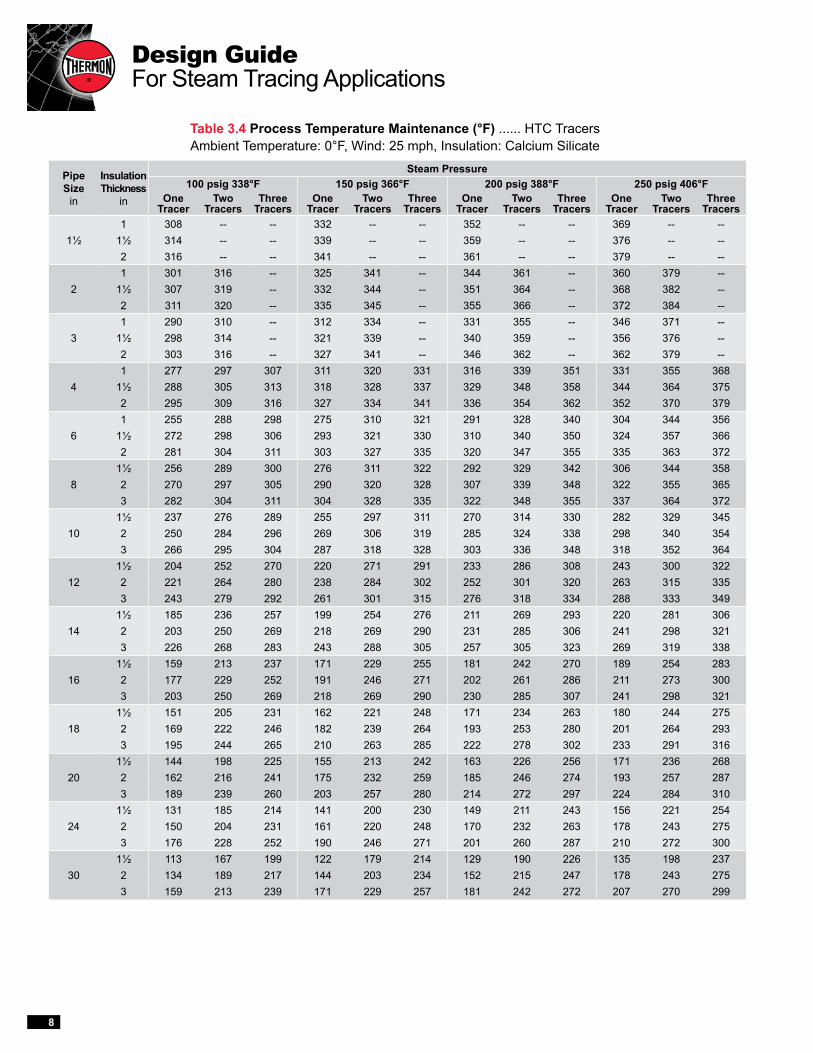
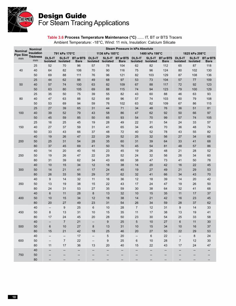
Step 3: Identify Base Maintain TemperatureApply the fixed design factors established in Step 1 and the variable design factors selected in Step 2 to Tables 3.1 through 3.8 (see below for determining which table to use). Each table is divided based on tracer type with rows denoting the nominal pipe diameter and columns denoting steam pressure (temperature) and number of tracers. All of the tables are based on a minimum ambi-ent temperature of 0°F (-18°C) and wind speeds of 25 mph (11 m/s).
Process Temperature Maintenance (Inch-Pound System) Tracer Type Steam Pressure Table Bare/BTS & Isolated 15, 30, 50 & 75 psig 3.1 Bare/BTS & Isolated 100, 150, 200 & 250 psig 3.2 Heat Transfer Compound 15, 30, 50 & 75 psig 3.3 Heat Transfer Compound 100, 150, 200 & 250 psig 3.4
Process Temperature Maintenance (SI System) Tracer Type Steam Pressure Table Bare/BTS & Isolated 205, 308, 446 & 618 kPa 3.5 Bare/BTS & Isolated 791, 1136, 1480 & 1825 kPa 3.6 Heat Transfer Compound 205, 308, 446 & 618 kPa 3.7 Heat Transfer Compound 791, 1136, 1480 & 1825 kPa 3.8
Example . . . A process line requires steam tracing. The particulars for the line are:
Pipe diameter ..............................................................10" Design process temperature ...................................250°F Insulation thickness .......................................................2" Steam pressure (temperature) ...............100 psig (338°F) Minimum ambient/wind speed ........................0°F/25 mph
Table 2.1 identifies the application as a “Medium-High” temperature category and indicates the need for a con-duction heater using heat transfer compound. Table 2.2 identifies that for a 10" diameter pipe maintaining 250°F, 2" thick insulation is needed. Based on these factors, use Table 3.4 to determine that one 3/8" or 1/2" diameter tube tracer with heat transfer compound will provide the desired maintain temperature.
Note . . .1. Table is based on calcium silicate insulation oversized by one nominal pipe
size to accommodate tracer. Refer to Table 4.2 for details on using other insu-lation materials.
Step 2: Select the Proper Thermon Steam Tracing Method
For a steam tracing system to perform at optimal levels, choose the type of tracer that most closely meets the process design requirements using Table 2.1 below.
Table 2.1 Process Temperature vs. Tracer Type
Pipe Size in (mm)
Temperature Ranges50°-100°F (10°-38°C)
101°-150°F (39°-66°C)
151°-200°F (67°-93°C)
201°-300°F (94°-149°C)
301°-400°F (150°-204°C)
1½ (40) 1 (25) 1 (25) 1 (25) 1 (25) 1 (25)2 (50) 1 (25) 1 (25) 1 (25) 1 (25) 1 (25)3 (80) 1 (25) 1 (25) 1 (25) 1 (25) 1 (25)4 (100) 1 (25) 1½ (40) 1½ (40) 1½ (40) 1½ (40)6 (150) 1 (25) 1½ (40) 1½ (40) 1½ (40) 2 (50)8 (200) 1½ (40) 1½ (40) 1½ (40) 2 (50) 2 (50)10 (250) 1½ (40) 1½ (40) 2 (50) 2 (50) 2 (50)12 (300) 1½ (40) 1½ (40) 2 (50) 2 (50) 2 (50)14 (350) 1½ (40) 1½ (40) 2 (50) 2 (50) 2½ (64)16 (400) 1½ (40) 2 (50) 2 (50) 2 (50) 2½ (64)18 (450) 1½ (40) 2 (50) 2 (50) 2½ (64) 2½ (64)20 (500) 2 (50) 2 (50) 2 (50) 2½ (64) 2½ (64)24 (600) 2 (50) 2 (50) 2½ (50) 2½ (64) 3 (64)30 (750) 2 (50) 2 (50) 2½ (50) 2½ (64) 3 (75)
Process Temperature Range Tracer Type
LOW 50°-100°F (10°-38°C) Isolated
MEDIUM-LOW 101°-150°F (39°-66°C) Isolated/Convection
MEDIUM 151°-200°F (67°-93°C) Convection/Conduction
MEDIUM-HIGH 201°-300°F (94°-149°C) Conduction
HIGH 301°-400°F (150°-204°C) Conduction

5
THERMON The Heat Tracing Specialists®
Notes . . . Tables 3.1 and 3.2 are based on calcium silicate insulation and give approximate values for cellular glass and perlite. All tracers are 3/8" O.D. tubing to provide for economical trap distances. Use Table 4.1 to adjust for ambient temperatures other than 0°F.
For pipe temperatures below 80°F, consider using cellular glass or other insulation materials with a low moisture permeability.
Table 3.1 Process Temperature Maintenance (°F) ...... IT, BT or BTS TracersAmbient Temperature: 0°F, Wind: 25 mph, Insulation: Calcium Silicate
Pipe Size
in
Insulation Thickness
in
Steam Pressure15 psig 250°F 30 psig 274°F 50 psig 298°F 75 psig 320°F
DLS-IT Isolated
SLS-IT Isolated
BT or BTS Bare
DLS-IT Isolated
SLS-IT Isolated
BT or BTS Bare
DLS-IT Isolated
SLS-IT Isolated
BT or BTS Bare
DLS-IT Isolated
SLS-IT Isolated
BT or BTS Bare
1½1 93 118 151 102 130 167 112 142 182 121 152 196
1½ 113 138 164 125 151 180 136 165 197 147 178 2122 121 145 171 134 160 188 146 175 206 157 188 222
21 83 106 142 91 116 157 101 127 171 108 138 184
1½ 97 121 161 108 133 177 118 146 193 127 157 2082 107 131 167 119 144 184 130 157 201 140 170 217
31 71 91 132 78 100 146 86 110 159 93 118 171
1½ 85 105 144 94 116 159 102 127 173 111 137 1872 95 116 153 104 128 168 115 140 184 124 151 198
41 59 75 120 65 83 132 71 91 144 77 98 156
1½ 72 90 132 80 100 146 87 109 159 95 117 1712 83 102 141 91 112 156 100 123 170 108 132 183
61 -- 55 81 50 60 89 53 66 98 58 72 106
1½ 58 70 99 64 77 110 70 85 120 76 92 1292 67 81 111 74 89 123 82 98 134 88 106 144
81½ -- 56 84 52 61 92 57 67 101 62 73 1092 58 67 98 64 75 108 71 82 118 76 89 1283 72 82 114 79 91 126 87 99 138 94 108 149
101½ -- -- 76 -- 54 84 50 60 92 55 65 1002 -- 58 87 54 65 97 60 71 106 65 77 1143 63 73 104 69 81 115 76 89 126 82 95 136
121½ -- -- 65 -- -- 72 -- 50 79 -- 54 852 -- 50 77 -- 55 85 51 61 93 55 66 1003 55 64 94 60 71 104 66 78 114 72 84 123
141½ -- -- 62 -- -- 69 -- -- 75 -- 52 822 -- -- 74 -- 52 81 -- 58 89 52 63 963 52 62 91 58 68 100 63 75 110 69 81 119
161½ -- -- 57 -- -- 63 -- -- 69 -- -- 752 -- -- 68 -- -- 75 -- 53 82 -- 57 893 -- 57 85 53 63 94 58 69 103 63 74 111
181½ -- -- 52 -- -- 58 -- -- 64 -- -- 692 -- -- 63 -- -- 70 -- -- 77 -- 52 833 -- 52 80 50 58 88 54 64 97 58 69 105
201½ -- -- -- -- -- 54 -- -- 59 -- -- 642 -- -- 59 -- -- 65 -- -- 71 -- 50 773 -- -- 76 -- 54 83 50 59 91 54 65 98
241½ -- -- -- -- -- -- -- -- 51 -- -- 562 -- -- 52 -- -- 58 -- -- 63 -- -- 683 -- -- 67 -- -- 75 -- 52 82 -- 57 89
301½ -- -- -- -- -- -- -- -- -- -- -- --2 -- -- -- -- -- -- -- -- -- -- -- --3 -- -- -- -- -- -- -- -- -- -- -- --

Design GuideFor Steam Tracing Applications
6
Table 3.2 Process Temperature Maintenance (°F) ...... IT, BT or BTS Tracers Ambient Temperature: 0°F, Wind: 25 mph, Insulation: Calcium Silicate
Pipe Size
in
Insulation Thickness
in
Steam Pressure100 psig 338°F 150 psig 366°F 200 psig 388°F 250 psig 406°F
DLS-IT Isolated
SLS-IT Isolated
BT or BTS Bare
DLS-IT Isolated
SLS-IT Isolated
BT or BTS Bare
DLS-IT Isolated
SLS-IT Isolated
BT or BTS Bare
DLS-IT Isolated
SLS-IT Isolated
BT or BTS Bare
1½1 128 161 207 138 173 223 146 184 236 153 192 247
1½ 155 188 224 167 202 241 177 215 255 185 224 2672 166 199 234 178 214 252 189 227 267 198 237 280
21 114 145 194 123 156 209 131 166 222 137 174 232
1½ 134 166 219 144 178 236 153 189 250 160 198 2622 147 179 228 159 193 246 168 204 261 176 214 273
31 98 125 181 106 135 195 112 143 206 118 149 216
1½ 116 145 197 126 156 212 133 165 225 140 173 2352 130 159 208 141 171 224 149 182 238 156 190 249
41 81 104 164 88 112 176 94 119 187 98 124 196
1½ 100 124 180 108 134 194 115 142 206 120 148 2162 114 139 193 123 150 208 130 159 221 137 167 231
61 61 76 112 66 82 120 71 87 128 74 92 134
1½ 80 97 136 86 105 147 92 111 156 96 116 1632 93 111 152 100 120 164 106 127 174 112 134 182
81½ 66 77 115 71 83 125 76 89 132 79 93 1382 81 94 134 87 101 145 92 107 154 97 113 1613 99 113 157 107 122 169 113 129 179 119 136 187
101½ 57 69 105 62 74 113 66 79 120 70 83 1262 69 81 120 74 87 129 79 93 138 83 98 1443 87 101 143 94 108 154 99 115 163 104 121 171
121½ -- 57 90 52 62 97 55 66 103 58 69 1082 58 70 106 63 75 114 67 80 121 71 84 1273 76 89 129 82 96 140 87 102 148 92 107 155
141½ -- 54 86 50 59 93 52 63 99 55 66 1042 55 66 101 60 71 110 64 76 116 67 80 1223 72 85 125 78 92 135 83 98 143 87 102 150
161½ -- 50 79 -- 53 85 -- 57 91 50 60 952 50 61 94 55 65 101 58 69 108 61 73 1133 66 79 117 72 85 127 77 90 134 80 95 141
181½ -- -- 73 -- 50 79 -- 52 84 -- 54 882 -- 55 87 50 60 94 53 64 100 56 67 1053 62 73 111 66 79 119 71 84 126 75 88 132
201½ -- -- 68 -- -- 73 -- -- 78 -- 50 822 -- 52 82 -- 55 88 50 59 94 51 62 993 57 68 104 62 74 112 66 78 119 69 82 125
241½ -- -- 59 -- -- 64 -- -- 68 -- -- 722 -- -- 72 -- -- 78 -- 51 83 -- 54 873 50 60 94 54 65 101 58 69 107 61 73 112
301½ -- -- -- -- -- -- -- -- -- -- -- --2 -- -- -- -- -- -- -- -- -- -- -- --3 -- -- -- -- -- -- -- -- -- -- -- --

7
THERMON The Heat Tracing Specialists®
Table 3.3 Process Temperature Maintenance (°F) ...... HTC TracersAmbient Temperature: 0°F, Wind: 25 mph, Insulation: Calcium Silicate
Notes . . . Tables 3.3 and 3.4 are based on calcium silicate insulation and give approximate values for cellular glass and perlite. Tracers are 3/8" or 1/2" O.D. tubing with TFK-4 channel. Use Table 4.1 to adjust for ambient temperatures other than 0°F.
With HTC and channel, the contact area is the same for 3/8" or 1/2" O.D. tracers; therefore, the pipe temperature is the same for either tracer under like conditions.
Pipe Size
in
Insulation Thickness
in
Steam Pressure15 psig 250°F 30 psig 274°F 50 psig 298°F 75 psig 320°F
One Tracer
Two Tracers
Three Tracers
One Tracer
Two Tracers
Three Tracers
One Tracer
Two Tracers
Three Tracers
One Tracer
Two Tracers
Three Tracers
1½1 226 -- -- 248 -- -- 271 -- -- 292 -- --
1½ 230 -- -- 253 -- -- 276 -- -- 298 -- --2 232 -- -- 256 -- -- 278 -- -- 300 -- --
21 221 232 -- 243 254 -- 265 278 -- 286 300 --
1½ 225 234 -- 248 256 -- 271 280 -- 291 302 --2 228 235 -- 251 258 -- 274 282 -- 295 304 --
31 213 227 -- 234 250 -- 255 273 -- 275 294 --
1½ 218 230 -- 240 253 -- 263 276 -- 283 298 --2 222 232 -- 244 255 -- 267 279 -- 288 300 --
41 204 217 225 224 239 248 244 261 271 263 282 291
1½ 212 223 229 232 246 252 254 268 275 274 289 2972 217 227 232 238 249 255 260 272 278 280 294 300
61 188 211 218 206 232 240 225 254 262 242 273 282
1½ 200 219 225 219 240 247 240 263 270 258 283 2912 207 223 227 227 245 250 247 267 273 267 288 294
81½ 189 212 219 207 232 241 226 254 263 243 274 2842 199 218 223 218 239 246 238 262 269 256 282 2893 207 223 228 228 246 251 249 268 274 267 289 295
101½ 175 202 212 192 223 233 209 243 255 225 261 2742 184 209 217 202 229 239 221 251 261 237 270 2813 196 217 223 215 238 246 235 260 268 253 280 289
121½ 151 185 199 166 203 218 181 222 238 194 239 2562 163 194 206 179 213 226 195 233 247 210 251 2663 179 205 215 196 225 236 214 246 258 230 265 277
141½ 137 174 189 150 191 208 164 208 227 176 224 2442 150 184 198 164 202 217 179 221 237 192 237 2553 167 197 208 183 216 229 200 236 250 215 254 269
161½ 117 157 175 129 173 192 140 188 209 151 202 2262 131 169 184 144 186 204 157 202 222 169 218 2393 150 184 198 164 202 217 179 221 238 192 237 256
181½ 111 152 170 123 166 187 133 181 204 143 195 2202 126 164 181 137 180 199 150 196 217 161 211 2343 144 180 195 158 198 214 173 215 234 186 232 251
201½ 106 146 166 116 161 182 127 175 198 137 188 2132 120 159 178 132 175 194 144 190 213 154 205 2293 139 176 192 153 193 211 166 211 230 180 227 247
241½ 97 137 158 106 151 173 116 164 189 125 176 2032 111 151 170 121 165 187 132 180 204 142 194 2193 130 169 186 143 185 204 156 202 222 168 217 239
301½ 84 123 147 92 135 161 100 147 176 108 158 1892 99 139 160 108 153 176 118 167 192 127 179 2063 117 157 176 128 172 193 140 188 211 151 202 226
Design GuideFor Steam Tracing Applications
8
Table 3.4 Process Temperature Maintenance (°F) ...... HTC TracersAmbient Temperature: 0°F, Wind: 25 mph, Insulation: Calcium Silicate
Pipe Size
in
Insulation Thickness
in
Steam Pressure100 psig 338°F 150 psig 366°F 200 psig 388°F 250 psig 406°F
One Tracer
Two Tracers
Three Tracers
One Tracer
Two Tracers
Three Tracers
One Tracer
Two Tracers
Three Tracers
One Tracer
Two Tracers
Three Tracers
1½1 308 -- -- 332 -- -- 352 -- -- 369 -- --
1½ 314 -- -- 339 -- -- 359 -- -- 376 -- --2 316 -- -- 341 -- -- 361 -- -- 379 -- --
21 301 316 -- 325 341 -- 344 361 -- 360 379 --
1½ 307 319 -- 332 344 -- 351 364 -- 368 382 --2 311 320 -- 335 345 -- 355 366 -- 372 384 --
31 290 310 -- 312 334 -- 331 355 -- 346 371 --
1½ 298 314 -- 321 339 -- 340 359 -- 356 376 --2 303 316 -- 327 341 -- 346 362 -- 362 379 --
41 277 297 307 311 320 331 316 339 351 331 355 368
1½ 288 305 313 318 328 337 329 348 358 344 364 3752 295 309 316 327 334 341 336 354 362 352 370 379
61 255 288 298 275 310 321 291 328 340 304 344 356
1½ 272 298 306 293 321 330 310 340 350 324 357 3662 281 304 311 303 327 335 320 347 355 335 363 372
81½ 256 289 300 276 311 322 292 329 342 306 344 3582 270 297 305 290 320 328 307 339 348 322 355 3653 282 304 311 304 328 335 322 348 355 337 364 372
101½ 237 276 289 255 297 311 270 314 330 282 329 3452 250 284 296 269 306 319 285 324 338 298 340 3543 266 295 304 287 318 328 303 336 348 318 352 364
121½ 204 252 270 220 271 291 233 286 308 243 300 3222 221 264 280 238 284 302 252 301 320 263 315 3353 243 279 292 261 301 315 276 318 334 288 333 349
141½ 185 236 257 199 254 276 211 269 293 220 281 3062 203 250 269 218 269 290 231 285 306 241 298 3213 226 268 283 243 288 305 257 305 323 269 319 338
161½ 159 213 237 171 229 255 181 242 270 189 254 2832 177 229 252 191 246 271 202 261 286 211 273 3003 203 250 269 218 269 290 230 285 307 241 298 321
181½ 151 205 231 162 221 248 171 234 263 180 244 2752 169 222 246 182 239 264 193 253 280 201 264 2933 195 244 265 210 263 285 222 278 302 233 291 316
201½ 144 198 225 155 213 242 163 226 256 171 236 2682 162 216 241 175 232 259 185 246 274 193 257 2873 189 239 260 203 257 280 214 272 297 224 284 310
241½ 131 185 214 141 200 230 149 211 243 156 221 2542 150 204 231 161 220 248 170 232 263 178 243 2753 176 228 252 190 246 271 201 260 287 210 272 300
301½ 113 167 199 122 179 214 129 190 226 135 198 2372 134 189 217 144 203 234 152 215 247 178 243 2753 159 213 239 171 229 257 181 242 272 207 270 299

9
THERMON The Heat Tracing Specialists®
Table 3.5 Process Temperature Maintenance (°C) ...... IT, BT or BTS TracersAmbient Temperature: -18°C, Wind: 11 m/s, Insulation: Calcium Silicate
Notes . . . Tables 3.5 and 3.6 are based on calcium silicate insulation and give approximate values for cellular glass and perlite. Bare trac-ers are 12 mm O.D. tubing to provide for economical trap distances. Isolated tracers have 10 mm O.D. tubing. Use Table 4.1 to adjust for ambient temperatures other than -18°C.
For pipe temperatures below 27°C, consider using cellular glass or other insulation materials with a low moisture permeability.
Nominal Pipe Size
mm
Nominal Insulation Thickness
mm
Steam Pressure in kPa Absolute205 kPa 121°C 308 kPa 134°C 446 kPa 148°C 618 kPa 160°C
DLS-IT Isolated
SLS-IT Isolated
BT or BTS Bare
DLS-IT Isolated
SLS-IT Isolated
BT or BTS Bare
DLS-IT Isolated
SLS-IT Isolated
BT or BTS Bare
DLS-IT Isolated
SLS-IT Isolated
BT or BTS Bare
4025 33 46 65 38 53 82 43 59 82 48 65 9040 41 55 73 48 63 86 54 70 91 59 77 10050 46 59 76 52 67 92 59 75 95 65 82 104
5025 27 40 60 32 46 68 37 52 76 41 57 8340 36 49 68 42 56 77 48 63 86 53 70 9450 41 54 72 47 61 89 53 69 99 59 75 99
8025 20 31 50 24 36 56 28 41 64 32 46 7040 29 41 59 34 47 67 39 53 75 44 59 8250 34 46 64 39 52 72 45 59 80 49 77 88
10025 14 24 42 18 28 48 22 32 55 25 36 6040 23 33 53 27 38 60 32 44 67 36 49 7350 28 38 57 32 44 65 37 50 73 42 68 80
15025 7 12 27 10 16 32 12 19 37 15 22 4140 15 21 38 18 26 44 22 30 49 25 34 5550 19 26 43 23 31 49 38 35 56 30 40 75
20040 9 13 29 11 17 34 15 20 39 17 23 4450 12 18 34 16 21 40 19 25 45 22 29 5080 22 28 45 26 32 52 30 37 59 34 42 65
25040 5 10 24 8 12 28 10 15 33 12 18 3750 9 13 29 11 17 34 14 20 39 17 23 4380 17 23 40 21 27 46 24 31 52 28 35 58
30040 -- 6 20 -- 9 24 6 11 28 9 14 3150 6 10 25 8 13 29 10 16 34 13 18 3880 13 19 36 17 23 41 20 27 47 23 30 52
35040 -- 5 18 -- 7 22 5 10 26 7 12 2950 -- 9 23 7 11 27 9 14 31 11 17 3580 12 17 34 15 21 39 18 25 45 21 28 50
40040 -- -- 15 -- 5 18 -- 7 22 5 10 2550 -- 6 20 -- 9 24 6 11 28 9 14 3180 10 15 31 12 18 36 15 22 41 18 25 45
45040 -- -- 12 -- -- 16 -- 5 19 -- 7 2250 -- -- 17 -- 7 21 -- 9 24 7 11 2880 8 12 28 10 16 33 13 19 37 16 22 42
50040 -- -- 10 -- -- 13 -- -- 16 -- 5 1950 -- -- 15 -- -- 18 -- 7 22 5 9 2580 6 10 25 8 13 30 11 16 34 13 19 39
60040 -- -- 7 -- -- 10 -- -- 12 -- -- 1550 -- -- 11 -- -- 14 -- -- 17 -- 6 2080 -- 7 21 5 10 25 7 12 29 10 15 33
75040 -- -- -- -- -- -- -- -- -- -- -- --50 -- -- -- -- -- -- -- -- -- -- -- --80 -- -- -- -- -- -- -- -- -- -- -- --
Design GuideFor Steam Tracing Applications
10
Table 3.6 Process Temperature Maintenance (°C) ...... IT, BT or BTS Tracers Ambient Temperature: -18°C, Wind: 11 m/s, Insulation: Calcium Silicate
Nominal Pipe Size
mm
Nominal Insulation Thickness
mm
Steam Pressure in kPa Absolute791 kPa 170°C 1136 kPa 185°C 1480 kPa 198°C 1825 kPa 208°C
DLS-IT Isolated
SLS-IT Isolated
BT or BTS Bare
DLS-IT Isolated
SLS-IT Isolated
BT or BTS Bare
DLS-IT Isolated
SLS-IT Isolated
BT or BTS Bare
DLS-IT Isolated
SLS-IT Isolated
BT or BTS Bare
4025 52 70 96 57 78 104 62 82 112 65 87 11840 64 82 106 70 90 116 75 96 124 80 102 13050 69 88 111 76 96 121 82 103 129 87 108 136
5025 44 62 88 49 68 97 53 73 104 57 77 10940 57 74 100 63 82 109 67 88 117 72 92 12350 63 80 105 69 88 115 74 94 123 79 100 129
8025 35 50 75 39 55 82 43 60 88 46 63 9340 47 63 88 52 69 96 57 74 103 60 79 10850 53 69 94 59 76 102 63 82 109 67 86 115
10025 27 39 65 31 44 71 34 48 76 36 51 8140 39 52 79 43 58 86 47 62 92 50 66 9750 45 59 85 50 65 93 54 70 99 57 74 105
15025 16 25 45 19 28 49 22 31 54 24 33 5740 27 37 59 31 41 65 34 45 70 36 48 7450 33 43 66 37 48 72 40 52 78 43 55 82
20040 19 26 47 22 29 52 25 32 56 27 34 6050 25 31 54 28 35 60 31 39 64 33 41 6880 37 45 69 41 50 76 45 54 81 48 57 86
25040 14 20 40 16 23 45 19 26 48 21 28 5250 19 26 47 22 29 52 24 32 56 26 34 6080 31 39 62 34 43 68 38 47 73 41 50 78
30040 10 15 34 12 18 38 14 20 42 16 22 4550 14 21 41 17 24 45 19 27 49 21 29 5380 26 33 56 29 37 62 32 41 66 34 43 70
35040 9 14 32 11 16 36 12 18 39 14 20 4250 13 19 38 15 22 43 17 24 47 19 26 5080 24 31 53 27 35 59 30 38 64 32 41 68
40040 6 11 28 8 13 32 10 15 35 11 17 3750 10 15 34 12 18 38 14 21 42 16 23 4580 20 27 49 23 31 54 26 34 59 28 37 62
45040 -- 9 25 6 10 28 7 12 31 9 14 3350 8 13 31 10 15 35 11 17 38 13 19 4180 17 24 45 20 28 50 23 30 54 25 33 58
50040 -- 7 21 -- 9 25 5 10 27 6 11 3050 6 10 27 8 13 31 10 15 34 10 16 3780 15 21 42 18 25 46 20 27 50 22 29 53
60040 -- -- 17 -- 5 20 -- 6 22 -- 8 2450 -- 7 22 -- 9 25 6 10 28 7 12 3080 11 17 36 13 20 40 15 22 43 17 24 47
75040 -- -- -- -- -- -- -- -- -- -- -- --50 -- -- -- -- -- -- -- -- -- -- -- --80 -- -- -- -- -- -- -- -- -- -- -- --

11
THERMON The Heat Tracing Specialists®
Notes . . .Tables 3.7 and 3.8 are based on calcium silicate insulation and give approximate values for cellular glass and perlite. Tracers are 10 or 12 mm O.D. tubing with TFK-4 channel. Use Table 4.1 to adjust for ambient temperatures other than -18°C.
With HTC and channel, the contact area is the same for 10 or 12 mm O.D. tracers; therefore, the pipe temperature is the same for either tracer under like conditions.
Table 3.7 Process Temperature Maintenance (°C) ...... HTC TracersAmbient Temperature: -18°C, Wind: 11 m/s, Insulation: Calcium Silicate
Nominal Pipe Size
mm
Nominal Insulation Thickness
mm
Steam Pressure in kPa Absolute205 kPa 121°C 308 kPa 134°C 446 kPa 148°C 618 kPa 160°C
One Tracer
Two Tracers
Three Tracers
One Tracer
Two Tracers
Three Tracers
One Tracer
Two Tracers
Three Tracers
One Tracer
Two Tracers
Three Tracers
4025 107 -- -- 120 -- -- 132 -- -- 144 -- --40 109 -- -- 122 -- -- 135 -- -- 147 -- --50 110 -- -- 123 -- -- 136 -- -- 148 -- --
5025 104 110 -- 117 122 -- 129 135 -- 140 147 --40 107 111 -- 120 124 -- 132 137 -- 144 149 --50 108 112 -- 121 125 -- 134 138 -- 146 150 --
8025 100 107 -- 111 119 -- 123 132 -- 134 144 --40 104 109 -- 116 122 -- 128 135 -- 139 147 --50 105 110 -- 117 123 -- 130 136 -- 141 148 --
10025 95 103 107 106 115 120 118 127 132 128 139 14440 100 107 110 112 119 122 124 131 135 135 143 14750 102 108 111 114 120 123 126 133 137 137 145 149
15025 87 100 103 97 111 115 107 123 128 117 134 13940 94 104 107 104 116 119 116 128 134 126 140 14450 96 105 108 108 118 121 125 131 137 130 142 146
20040 87 100 104 97 112 116 108 124 128 118 134 14050 91 102 106 102 114 118 112 126 131 122 137 14280 97 106 109 109 118 121 120 131 134 131 142 146
25040 79 94 100 88 106 111 98 117 124 107 127 13450 83 98 102 93 109 114 103 120 126 112 131 13780 91 102 106 102 114 118 113 126 131 123 138 142
30040 67 86 93 76 96 104 84 107 116 92 117 12650 73 90 96 82 101 108 91 111 119 99 121 13080 83 97 102 92 108 114 102 120 126 111 130 137
35040 60 80 88 67 90 99 75 99 110 82 108 11950 65 84 92 73 94 103 82 105 114 89 114 12480 76 92 99 85 103 110 94 114 122 103 124 132
40040 49 71 81 56 80 90 62 88 100 68 96 10950 55 76 85 62 85 95 69 94 105 76 103 11580 67 85 93 75 95 104 83 106 115 91 115 125
45040 46 68 78 52 76 88 58 85 97 64 93 10650 52 73 83 58 82 93 65 91 103 71 99 11280 64 83 91 72 93 102 80 103 113 87 112 123
50040 43 65 76 49 73 85 55 81 94 60 89 10350 49 71 81 55 79 90 62 88 100 68 96 10980 61 81 90 68 91 100 77 101 111 84 110 121
60040 38 60 71 43 68 80 49 75 89 54 82 9750 43 66 76 49 74 86 56 82 95 61 90 10480 56 77 86 63 86 96 71 96 107 77 104 117
75040 31 54 66 36 60 73 41 68 82 45 74 8950 37 39 71 42 67 79 48 75 89 52 81 9780 49 71 82 55 80 91 63 89 102 68 97 110

Design GuideFor Steam Tracing Applications
12
Table 3.8 Process Temperature Maintenance (°C) ...... HTC Tracers Ambient Temperature: -18°C, Wind: 11 m/s, Insulation: Calcium Silicate
Nominal Pipe Size
mm
Nominal Insulation Thickness
mm
Steam Pressure in kPa Absolute791 kPa 170°C 1136 kPa 185°C 1480 kPa 198°C 1825 kPa 208°C
One Tracer
Two Tracers
Three Tracers
One Tracer
Two Tracers
Three Tracers
One Tracer
Two Tracers
Three Tracers
One Tracer
Two Tracers
Three Tracers
4025 153 -- -- 166 -- -- 177 -- -- 186 -- --40 156 -- -- 169 -- -- 180 -- -- 190 -- --50 157 -- -- 170 -- -- 182 -- -- 191 -- --
5025 149 156 -- 162 170 -- 173 181 -- 182 191 --40 153 158 -- 166 172 -- 177 184 -- 186 194 --50 155 160 -- 168 174 -- 179 185 -- 188 197 --
8025 142 152 -- 155 165 -- 165 176 -- 174 190 --40 148 156 -- 161 169 -- 171 180 -- 180 191 --50 150 157 -- 163 171 -- 174 182 -- 183 194 --
10025 136 147 153 148 160 166 158 170 177 166 179 18640 143 152 156 155 165 170 165 176 181 174 185 19150 146 154 158 158 167 171 174 178 183 178 188 192
15025 124 142 148 135 155 160 144 165 171 152 173 18040 134 148 152 145 161 166 155 172 176 163 181 18650 138 151 154 149 163 168 160 174 179 168 183 188
20040 125 143 148 136 155 161 145 165 172 153 174 18150 130 146 151 141 158 164 151 169 175 158 178 18480 139 151 155 151 164 169 161 175 179 169 184 189
25040 113 135 143 124 147 155 132 156 165 139 165 17450 120 139 146 130 151 158 139 161 169 146 169 17880 130 146 151 142 159 164 151 169 175 159 178 185
30040 98 124 134 107 134 145 114 143 155 120 151 16350 105 129 138 114 140 150 122 149 160 128 157 16880 118 138 145 128 150 158 137 160 168 144 168 177
35040 87 115 126 95 125 137 102 134 147 107 140 15450 95 121 131 103 132 143 110 140 153 116 148 16080 109 132 140 119 143 153 127 153 163 134 161 171
40040 73 103 116 80 112 126 85 119 134 90 125 14250 81 109 122 88 119 133 94 127 141 99 134 14980 96 122 133 105 133 144 112 142 154 118 149 162
45040 68 98 112 75 107 122 80 115 131 85 121 13750 76 106 119 83 115 129 89 122 138 94 129 14580 93 119 130 101 130 142 108 138 151 113 146 159
50040 64 95 109 71 103 119 76 110 127 80 116 13450 72 102 116 79 111 126 85 118 134 89 125 14180 89 116 128 97 127 139 104 135 148 109 142 156
60040 58 88 103 63 96 112 68 102 120 72 108 12650 65 95 110 72 104 120 77 111 128 81 117 13580 82 111 124 90 121 134 96 129 143 101 135 151
75040 49 79 95 54 86 103 58 92 111 61 97 11750 56 87 103 62 94 111 67 101 119 70 107 12680 73 103 117 80 112 127 86 120 136 90 126 143

13
THERMON The Heat Tracing Specialists®
Table 4.1 Ambient Temperature Adjustment Factors Process Temperature Change Coefficient Per Degree Change
in Ambient Temperature
Step 4: Apply Any Adjustment FactorsAmbient Temperature . . . If the minimum ambient will differ from the base level of 0°F (-18°C) estab-lished in Step 3, use Table 4.1 to apply an ambient correction factor. Multiply this coefficient by the dif-ference in the ambient temperature and apply the result to the process temperature.
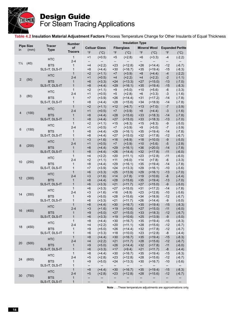
Insulation Materials . . . When insulation materials other than calcium silicate are used, it will be nec-essary to apply an insulation correction factor. Use Table 4.2 to add or subtract the applicable value to the temperature maintenance value established in Step 3.
Note: If both the ambient temperature and the insulation material differ from the 0°F (-18°C) and calcium silicate base values established in Step 3, apply the ambient temperature change first fol-lowed by the insulation material change.
Examples . . . Using the information from the example on page 4:
1. What would be the effect on the pipe main-tain temperature if the ambient temperature were -20°F instead of 0°F?
Locate the 10" diameter pipe size and 2" thick insulation rows under the one heat transfer compound (HTC) column to find a coefficient multiplier of 0.24. Multiply this val-ue by the ambient temperature change: 0.24 x 20 = 4.8°F
Rounding 4.8 to the nearest whole value results in 5°F. Subtracting this number from the 250°F pipe temperature previously estab-lished results in a new maintain temperature of 245°F.
2. What would be the effect on the pipe main-tain temperature if the thermal insulation was mineral wool?
In the mineral wool column of Table 4.2, find the appropriate value for a 10" diameter line utilizing HTC. Apply this value (+23°F) to the 250°F maintain temperature established in Step 3 to obtain a new maintain temperature of 273°F.
Nominal Pipe Size in (mm)
Nominal Insulation Thickness in (mm)
Number and Type of Tracer(s)
One DLS-IT
One SLS-IT
One BT or BTS
One HTC
Two HTC
Three HTC
1½ (40)1 (25) .62 .53 .39 .08 -- --
1½ (40) .55 .45 .34 .07 -- --2 (50) .51 .42 .31 .06 -- --
2 (50)1 (25) .66 .57 .43 .10 .06 --
1½ (40) .61 .51 .35 .08 .05 --2 (50) .57 .47 .33 .07 .05 --
3 (80)1 (25) .71 .63 .47 .13 .09 --
1½ (40) .66 .57 .42 .11 .07 --2 (50) .62 .53 .39 .10 .07 --
4 (100)1 (25) .76 .70 .52 .17 .11 .08
1½ (40) .71 .64 .47 .14 .09 .072 (50) .61 .59 .43 .12 .08 .06
6 (150)1 (25) .82 .77 .67 .23 .15 .11
1½ (40) .76 .72 .60 .18 .12 .092 (50) .73 .67 .52 .16 .10 .07
8 (200)1½ (40) .81 .77 .66 .23 .14 .112 (50) .76 .72 .60 .19 .11 .093 (75) .71 .67 .54 .16 .09 .07
10 (250)1½ (40) .83 .80 .69 .28 .17 .132 (50) .80 .76 .65 .24 .15 .123 (75) .75 .70 .58 .20 .12 .10
12 (300)1½ (40) .86 .83 .74 .38 .25 .192 (50) .83 .79 .69 .33 .21 .163 (75) .77 .74 .62 .28 .17 .13
14 (350)1½ (40) .87 .84 .74 .44 .29 .232 (50) .84 .80 .70 .39 .25 .193 (75) .79 .75 .63 .32 .20 .15
16 (400)1½ (40) .88 .85 .77 .52 .36 .292 (50) .85 .82 .72 .47 .31 .243 (75) .80 .77 .65 .39 .26 .20
18 (450)1½ (40) -- .87 .78 .54 .38 .312 (50) .86 .84 .74 .49 .33 .263 (75) .82 .78 .68 .42 .27 .27
20 (500)1½ (40) -- .88 .80 .57 .40 .322 (50) .88 .85 .76 .51 .35 .283 (75) .83 .80 .69 .44 .29 .22
24 (600)1½ (40) -- -- .82 .60 .44 .352 (50) -- .87 .79 .54 .38 .303 (75) .85 .82 .76 .47 .31 .24
30 (750)1½ (40) -- -- -- .65 .49 .392 (50) -- -- -- .59 .42 .323 (75) -- -- -- .51 .35 .28
Design GuideFor Steam Tracing Applications
14
Table 4.2 Insulation Material Adjustment Factors Process Temperature Change for Other Insulants of Equal Thickness
Note . . .These temperature adjustments are approximations only.
Pipe Size in (mm)
Tracer Type
Number of
Tracers
Insulation TypeCelluar Glass Fiberglass Mineral Wool Expanded Perlite
°F (°C) °F (°C) °F (°C) °F (°C)
1½ (40)HTC 1 +1 (+0.5) +5 (+2.8) +6 (+3.3) -4 (-2.2)
2-4 -- -- -- -- -- -- -- --BTS 1 +4 (+2.2) +23 (+12.8) +26 (+14.4) -12 (-6.7)
SLS-IT, DLS-IT 1 +8 (+4.4) +30 (+16.7) +35 (+19.4) -15 (-8.3)
2 (50)HTC 1 +2 (+1.1) +7 (+3.9) +8 (+4.4) -4 (-2.2)
2-4 +1 (+0.5) +4 (+2.2) +4 (+2.2) -2 (-1.1)BTS 1 +6 (+3.3) +24 (+13.3) +27 (+15.0) -13 (-7.0)
SLS-IT, DLS-IT 1 +8 (+4.4) +29 (+16.1) +35 (+19.4) -15 (-8.3)
3 (80)HTC 1 +2 (+1.1) +9 (+5.0) +10 (+5.6) -6 (-3.3)
2-4 +1 (+0.5) +5 (+2.8) +6 (+3.3) -3 (-1.6)BTS 1 +7 (+3.9) +26 (+14.4) +31 (+17.2) -14 (-7.8)
SLS-IT, DLS-IT 1 +8 (+4.4) +28 (+15.6) +34 (+18.9) -14 (-7.8)
4 (100)HTC
1 +2 (+1.1) +12 (+6.7) +13 (+7.0) -7 (-3.9)2-4 +1 (+0.5) +7 (+3.9) +8 (+4.4) -3 (-1.6)
BTS 1 +8 (+4.4) +28 (+15.6) +33 (+18.3) -14 (-7.8)SLS-IT, DLS-IT 1 +8 (+4.4) +27 (+15.0) +33 (+18.3) -13 (-7.0)
6 (150)HTC 1 +2 (+1.1) +15 (+8.3) +15 (+8.3) -9 (-5.0)
2-4 +1 (+0.5) +7 (+3.9) +9 (+5.0) -7 (-3.9)BTS 1 +8 (+4.4) +29 (+16.1) +35 (+19.4) -14 (-7.8)
SLS-IT, DLS-IT 1 +8 (+4.4) +27 (+15.0) +32 (+17.8) -12 (-6.7)
8 (200)HTC 1 +3 (+1.6) +16 (+8.9) +18 (+10.0) -9 (-5.0)
2-4 +1 (+0.5) +7 (+3.9) +10 (+5.6) -5 (-2.8)BTS 1 +8 (+4.4) +29 (+16.1) +36 (+20.0) -14 (-7.8)
SLS-IT, DLS-IT 1 +8 (+4.4) +26 (+14.4) +32 (+17.8) -11 (-6.0)
10 (250)HTC 1 +4 (+2.2) +20 (+11.1) +23 (+12.8) -11 (-6.0)
2-4 +2 (+1.1) +11 (+6.0) +14 (+7.8) -6 (-3.3)BTS 1 +8 (+4.4) +29 (+16.1) +35 (+19.4) -14 (-7.8)
SLS-IT, DLS-IT 1 +7 (+3.9) +24 (+13.3) +29 (+16.1) -10 (-5.6)
12 (300)HTC 1 +6 (+3.3) +25 (+13.9) +29 (+16.1) -13 (-7.0)
2-4 +3 (+1.6) +14 (+7.8) +19 (+10.6) -8 (-4.4)BTS 1 +8 (+4.4) +28 (+15.6) +35 (+19.4) -13 (-7.0)
SLS-IT, DLS-IT 1 +6 (+3.3) +21 (+11.7) +27 (+15.0) -9 (-5.0)
14 (350)HTC 1 +6 (+3.3) +27 (+15.0) +31 (+17.2) -14 (-7.8)
2-4 +3 (+1.6) +16 (+8.9) +23 (+12.8) -10 (-5.6)BTS 1 +9 (+5.0) +28 (+15.6) +34 (+18.9) -12 (-6.7)
SLS-IT, DLS-IT 1 +6 (+3.3) +21 (+11.7) +26 (+14.4) -9 (-5.0)
16 (400)HTC 1 +8 (+4.4) +30 (+16.7) +35 (+19.4) -15 (-8.3)
2-4 +3 (+1.6) +19 (+10.6) +27 (+15.0) -11 (-6.0)BTS 1 +9 (+5.0) +27 (+15.0) +33 (+18.3) -12 (-6.7)
SLS-IT, DLS-IT 1 +6 (+3.3) +19 (+10.6) +25 (+13.9) -9 (-5.0)
18 (450)HTC 1 +8 (+4.4) +30 (+16.7) +35 (+19.4) -15 (-8.3)
2-4 +4 (+2.2) +20 (+11.1) +28 (+15.6) -12 (-6.7)BTS 1 +9 (+5.0) +26 (+14.4) +32 (+17.8) -12 (-6.7)
SLS-IT, DLS-IT 1 +6 (+3.3) +18 (+10.0) +23 (+12.8) -8 (-4.4)
20 (500)HTC 1 +8 (+4.4) +30 (+16.7) +35 (+19.4) -15 (-8.3)
2-4 +4 (+2.2) +21 (+11.7) +28 (+15.6) -12 (-6.7)BTS 1 +9 (+5.0) +26 (+14.4) +32 (+17.8) -11 (-6.0)
SLS-IT, DLS-IT 1 +6 (+3.3) +17 (+9.4) +21 (+11.7) -8 (-4.4)
24 (600)HTC 1 +8 (+4.4) +30 (+16.7) +35 (+19.4) -15 (-8.3)
2-4 +5 (+2.8) +23 (+12.8) +28 (+15.6) -12 (-6.7)BTS 1 +9 (+5.0) +24 (+13.3) +30 (+16.7) -10 (-5.6)
SLS-IT, DLS-IT 1 -- -- -- -- -- -- -- --
30 (750)HTC 1 +8 (+4.4) +30 (+16.7) +35 (+19.4) -15 (-8.3)
2-4 +5 (+2.8) +23 (+12.8) +28 (+15.6) -12 (-6.7)BTS 1 -- -- -- -- -- -- -- --
SLS-IT, DLS-IT 1 -- -- -- -- -- -- -- --

15
THERMON The Heat Tracing Specialists®
Steam Pressure kPa
psig Absolute
Tracer Type
Number of
Tracers
Tubing Size 3/8" O.D.
(10 mm)1,2
ft (m)
1/2" O.D. (12 mm)3
ft (m)
3/4" O.D. (20 mm)4
ft (m)
15 (205)
HTC1 50 (15) 75 (23) 135 (41)2 65 (20) 95 (29) 170 (52)3 75 (23) 110 (34) 195 (59)
BT or BTS 1 75 (23) 110 (34) --DLS-IT 1 125 (38) -- --SLS-IT 1 115 (35) -- --
30 (308)
HTC1 60 (18) 100 (30) 185 (56)2 90 (27) 125 (38) 230 (70)3 105 (32) 145 (44) 265 (81)
BT or BTS 1 100 (30) 151 (46) --DLS-IT 1 170 (52) -- --SLS-IT 1 150 (46) -- --
50 (446)
HTC1 80 (24) 130 (40) 230 (70)2 115 (35) 160 (49) 290 (88)3 135 (41) 185 (56) 335 (102)
BT or BTS 1 125 (38) 190 (58) --DLS-IT 1 215 (66) -- --SLS-IT 1 185 (56) -- --
75 (618)
HTC1 95 (29) 155 (47) 280 (85)2 135 (41) 195 (59) 350 (107)3 165 (50) 225 (69) 405 (123)
BT or BTS 1 150 (46) 235 (72) --DLS-IT 1 260 (79) -- --SLS-IT 1 225 (69) -- --
100 (791)
HTC1 110 (34) 180 (55) 320 (98)2 155 (47) 225 (69) 400 (122)3 190 (58) 255 (78) 465 (142)
BT or BTS 1 175 (53) 270 (82) --DLS-IT 1 300 (91) -- --SLS-IT 1 380 (116) -- --
150 (1136)
HTC1 130 (40) 220 (67) 390 (119)2 190 (58) 270 (82) 490 (149)3 230 (70) 310 (94) 500 (152)
BT or BTS 1 215 (66) 325 (99) --DLS-IT 1 355 (108) -- --SLS-IT 1 315 (96) -- --
200 (1480)
HTC1 150 (46) 250 (76) 450 (137)2 215 (66) 310 (94) 500 (152)3 260 (79) 360 (110) 500 (152)
BT or BTS 1 245 (75) 375 (114) --DLS-IT 1 405 (123) -- --SLS-IT 1 355 (108) -- --
250 (1825)
HTC1 170 (52) 280 (85) 500 (152)2 240 (73) 345 (105) 500 (152)3 290 (88) 395 (120) 500 (152)
BT or BTS 1 270 (82) 415 (126) --DLS-IT 1 450 (137) -- --SLS-IT 1 390 (119) -- --
Table 5.1 Trapping DistancesBased on 1½" (50 mm) Calcium Silicate Insulation
Step 5: Determine Steam Tracing Circuit Lengths
Steam tracing circuit lengths are frequently short due to the length or configuration of the traced piping and equipment. However, on long transfer lines, long circuit lengths are desirable to minimize the number of supply lines, valves and trapping stations required. Table 5.1 is based on 1½" calci-um silicate insulation, maximum pipe size group-ing, and variables for tracer size, conductance and low temperature limitations. Longer tracer runs may be possible based on a given pipe size, insulation type and thickness and allowable circuit pressure drop. Thermon’s CompuTrace design and selection program should be used to obtain optimal circuit lengths based on application-specif-ic design conditions.
The trapping distances found in Table 5.1 are based on tracer runs where the accumulated verti-cal tracer rise (AVTR) in feet does not exceed 15% of the inlet steam pressure as described below. It is important to consider the amount of vertical trac-er rise when laying out steam tracing circuitry.
AVTR . . . The sum of all the increases in ele-vation is called the accumulated vertical tracer rise. A field-tested approach is to limit the AVTR (numerically) for any steam tracing circuit to 15% of the inlet steam pressure. For example, with an inlet steam pressure of 50 psig, the AVTR should not exceed 7.5 feet. The approximate multiplier for pressure in kilopascals is 0.0066 to arrive at allowable AVTR in meters (see Figure 5.1). Since kilopascals are usually given in absolute pressure, subtract 101 kPa from kPa absolute before using the 0.0066 multiplier. No adjustment in the trap-ping distance from the charts is necessary if the above AVTR limit is adhered to and if the pressure drop is limited to 10% for computer-generated trapping distances. However, reductions in length are required for pressure losses due to bends, valves and fittings as shown in Table 5.2.
Notes . . .1. Maximum pipe size 8" (200 mm).2. For SLS-IT and DLS-IT, distance is based on maximum pipe size that
can be held at 50°F (10°C) or above.3. Maximum pipe size 24" (600 mm).4. Maximum pipe size 30" (750 mm).
( )

Design GuideFor Steam Tracing Applications
16
A
B
C
D
S
Figure 5.1
Table 5.2 Circuit Length Allowances
Step 6: Choose Options/AccessoriesThermon offers a variety of accessories to simplify the installation of isolated, convection and conduction trac-ers. Figure 6.1 identifies the typical accessories and their uses. For specific information on the accessories used with each product, refer to the Thermon product specifi-cation sheet for the tracer type/material.
Isolated Tracers . . . SafeTrace SLS-IT and DLS-IT tracers are attached to the process pipe with tempera-ture-rated tape while the ends are protected from mois-ture penetration by self- vulcanizing silicone rubber tape.
Convection Tracers . . . Bare tracers are typically in-stalled with stainless steel banding. SafeTrace BTS trac-ers may be installed with the same tape used for SLS-IT and DLS-IT tracers. No end preparation is required for BTS tracers.
Conduction Tracers . . . Accessories to install Thermon heat transfer compounds include stainless steel banding, crimp seals, banding tools and galvanized steel channel.
Steam Supply and Condensate Return . . . Every steam tracing circuit requires a method to move the steam medium from the supply header to the tracer’s starting point and from the tracer’s end point to a con-densate return manifold. SafeTrace SLS-IT and DLS-IT isolated tracers, because of their thermal retardant char-acteristics, can be installed continuously from the supply header, along the length of traced pipe and to the con-densate return manifold.
When the tracers will be convection or conduction trac-ers, separate steam supply and condensate return lines are required. Thermon simplifies this requirement with ThermoTube® preinsulated tubing. These copper or stainless steel tubes, avail-able in numerous diame-ters, utilize nonhygroscopic glass fiber insulation, a heat reflective foil wrap and a weather-resistant outer cov-ering. The preinsulated fea-ture of ThermoTube allows installation to be completed in one step as opposed to multiple steps required when using field-insulated materials. For additional product in-formation, refer to Thermon Form TSP0009.
Table 5.3 Header Sizing
Note . . . The equivalent lengths of fittings and bends in a tracing circuit must be sub-tracted from the circuit lengths determined in Table 5.1.
AVTR = A + B + C + D
Type of Bend or Fitting
Equivalent Length ft (m)
45° 0.7 (0.2)
90° 1.0 (0.3)
180° 1.6 (0.49)
Gate Valve 0.7 (0.2)
Globe Valve 17.0 (5.2)
Recommended Header Size for Supplying Steam Tracer LinesHeader Size Number of Tracersin (mm) 3/8" (10 mm) 1/2" (12 mm) 3/4" (20 mm)
3/4 (20) 3 2 --
1 (25) 4 to 8 3 to 5 2
1½ (40) 9 to 24 6 to 15 3 to 6
2 (50) 25 to 48 16 to 30 7 to 13
Recommended Header Size for Condensate LinesHeader Size Number of Tracersin (mm) 3/8" (10 mm) 1/2" (12 mm) 3/4" (20 mm)
1 (25) Up to 8 Up to 5 Up to 2
1½ (40) 9 to 16 6 to 10 3 to 4
2 (50) 17 to 40 11 to 25 5 to 11

17
THERMON The Heat Tracing Specialists®
FT-1H . . . fixing tape for circum-ferential banding of SafeTrace tracer to piping every 12" (300 mm) or as required by code or specification.
Product Rating:Maximum Exposure Temperature 500°F (260°C) Minimum Installation Temperature -40°F (-40°C)
FAK-7 . . . each kit contains a roll of self-vulcanizing silicone rubber tape and RTV sealant. The kit contains sufficient materials to waterproof approximately six ter-minations. No heat gun or special tools are needed for installation.
Product Rating:Maximum Exposure Temperature 400°F (204°C)Minimum Application Temperature -64°F (-54°C)
TFK-4 . . . galvanized steel channel covers heat transfer compound applied to 3/8" or 1/2" O.D. tube tracers.TFK-7 . . . galvanized steel channel covers heat transfer com-pound applied to 3/4" O.D. tube or 1/2" NPS pipe tracers.TFK-9 . . . galvanized steel channel covers heat transfer com-pound applied to 1" O.D. tube and 3/4" or 1" NPS pipe tracers.
Stainless Steel Banding . . . used to secure tracer, compound and chan-nel to piping.• T2SSB (.50" x .020") for 3/8"
and 1/2" O.D. tube tracers.• T3SSB (.50" x .030") for 3/4"
and 1" O.D. tube tracers and NPS pipe tracers.
C001 . . . banding tool for apply-ing tension to T2SSB or T3SSB banding.1950A . . . crimping tool for T34PB-CR seals.T34PB-CR . . . crimp seals for fastening tensioned banding.
Basic Accessories . . .
Figure 6.1 Typical Steam Tracing System
Isolated TracerAttachment Tape
ThermoTube
Convection Tracer
Conduction Tracer
TFK Channel
Stainless Steel Banding
FAK-7
Trap Station (Typical)
Condensate Return Manifold
Steam Supply Manifold

Design GuideFor Steam Tracing Applications
18
Design Optimization Tips . . .To ensure a properly operating steam tracing system and avoid commonly made mistakes, the following steam tracing recommendations have been compiled: 1. Select the tracer type that most closely meets the
process design temperature requirements. a. Conserves energy. b. Avoids the effects of overheating.
2. Use only one tracer per process pipe where possi-ble to reduce the number of trap stations, isolation valves and fittings required. (Certain critical pro-cess lines may require a redundant heater.)
a. Reduces initial cost. b. Eliminates maintenance of omitted materials.
3. Select a tracer that will meet the above conditions with existing steam pressure (up to 250 psig, 1825 kPa) where possible to decrease the use of pressurereducing valves and increase distance between traps, thus reducing the number of trap stations required. Isolated tracers can provide a low conductive heat path to reduce temperatures and conserve energy.
a. Reduces installation costs. b. Eliminates maintenance of omitted materials.
4. Use conduction tracers rather than steam-jacketed pipe where possible.
a. Significantly reduces material and labor costs. b. Provides flexibility for maintenance. c. Greatly reduces the number of trap stations re-
quired, forestalling future maintenance costs. d. Can significantly reduce energy consumption.
5. Use flash steam from condensate or steam from exothermic processes where available.
a. Significantly reduces energy costs. b. Low pressure steam provides more usable en-
thalpy, further increasing efficiency.
6. Use tubing rather than pipe for the tracer. a. Reduces initial labor cost due to ease of installa-
tion. b. Reduces number of fittings required, lowering
risk of steam leaks and future maintenance.
7. Use appropriate trapping distance determinations rather than rule-of-thumb distances which may not provide cost-effective lengths where long piping runs exist.
a. Reduces the number of trap stations and isola-
tion valves and thus material and installation costs. b. Eliminates maintenance of omitted materials.
8. Use preinsulated steam supply and condensate return lines.
a. Reduces labor and energy costs over field-in-stalled and insulated lines.
b. Extruded outer jacket ensures that the thermal insulation is always weather-protected.
9. Use prefabricated steam supply and condensate collection manifolds for multiple tracing circuits.
a. Provides centralized location for steam distribu-tion and condensate collection.
b. Minimizes design time and installation costs. c. Condensate collection manifolds with an internal
siphon pipe prevent freezing and water hammer during start-up.
10. Use prefabricated trap stations. a. Minimizes installation and labor costs. b. Standardized design reduces maintenance and
inventory.
Design Tips on Tracers . . .For nearly every application, the following comments on steam tracer selection will apply: • One BT or BTS bare convection tracer is the least
expensive tracing system to install. • Multiple BT or BTS tracers cannot be economically
justified when one tracer with heat transfer com-pound (HTC) will suffice because of the additional steam supply connections and trap assemblies required. BT or BTS tracers may be doubled back where allowable pressure drops are not exceeded.
• Spiraled BT or BTS tracers on horizontal runs are not recommended because circumferential ex-pansion reduces the heat transfer coefficient (by increasing the air gap between the tracer and the pipe) and the increased number of pockets requires more frequent trapping.
• Isolated tracers (IT) provide energy savings in the range of 25% to 50% over bare convection tracers where they meet the process temperature require-ments.
• In all cases, tracers that provide a measure of safety to aid compliance with applicable standards should be chosen.

19
THERMON The Heat Tracing Specialists®
Properties of Saturated Steam (Inch-Pound, °F Units)
Gauge Pressure
psig
Temp. °F
Heat Btu/lb
Specific Volume cu ft/lb
Gauge Pressure
psig
Temp. °F
Heat Btu/lb
Specific Volume cu ft/lbSensible Latent Total Sensible Latent Total
0 212 180 970 1150 26.8 105 341 312 878 1190 3.741 215 183 968 1151 25.2 110 344 316 875 1191 3.592 219 187 966 1153 23.5 115 347 319 873 1192 3.463 222 190 964 1154 22.3 120 350 322 871 1193 3.344 224 192 962 1154 21.4 125 353 325 868 1193 3.235 227 195 960 1155 20.1 130 356 328 866 1194 3.126 230 198 959 1157 19.4 135 358 330 864 1194 3.027 232 200 957 1157 18.7 140 361 333 861 1194 2.928 233 201 956 1157 18.4 145 363 336 859 1195 2.849 237 205 954 1159 17.1 150 366 339 857 1196 2.7410 239 207 953 1160 16.5 155 368 341 855 1196 2.6812 244 212 949 1161 15.3 160 371 344 853 1197 2.6014 248 216 947 1163 14.3 165 373 346 851 1197 2.5416 252 220 944 1164 13.4 170 375 348 849 1197 2.4718 256 224 941 1165 12.6 175 377 351 847 1198 2.4120 259 227 939 1166 11.9 180 380 353 845 1198 2.3422 262 230 937 1167 11.3 185 382 355 843 1198 2.2924 265 233 934 1167 10.8 190 384 358 841 1199 2.2426 268 236 933 1169 10.3 195 386 360 839 1199 2.1928 271 239 930 1169 9.85 200 388 362 837 1199 2.1430 274 243 929 1172 9.46 205 390 364 836 1200 2.0932 277 246 927 1173 9.10 210 392 366 834 1200 2.0534 279 248 925 1173 8.75 215 394 368 832 1200 2.0036 282 251 923 1174 8.42 220 396 370 830 1200 1.9638 284 253 922 1175 8.08 225 397 372 828 1200 1.9240 286 256 920 1176 7.82 230 399 374 827 1201 1.8942 289 258 918 1176 7.57 235 401 376 825 1201 1.8544 291 260 917 1177 7.31 240 403 378 823 1201 1.8146 293 262 915 1177 7.14 245 404 380 822 1202 1.7848 295 264 914 1178 6.94 250 406 382 820 1202 1.7550 298 267 912 1179 6.68 255 408 383 819 1202 1.7255 300 271 909 1180 6.27 260 409 385 817 1202 1.6960 307 277 906 1183 5.84 265 411 387 815 1202 1.6665 312 282 901 1183 5.49 270 413 389 814 1203 1.6370 316 286 898 1184 5.18 275 414 391 812 1203 1.6075 320 290 895 1185 4.91 280 416 392 811 1203 1.5780 324 294 891 1185 4.67 285 417 394 809 1203 1.5585 328 298 889 1187 4.44 290 418 395 808 1203 1.5390 331 302 886 1188 4.24 295 420 397 806 1203 1.4995 335 305 883 1188 4.05 300 421 398 805 1203 1.47100 338 309 880 1189 3.89

Design GuideFor Steam Tracing Applications
20
Properties of Saturated Steam (SI Metric Units)
Pressure kPa
Absolute
Temp. °C
Heat kJ/kg
Specific Volume
m /kg
Pressure kPa
Absolute
Temp. °C
Heat kJ/kg
Specific Volume m3/kgSensible Latent Total Sensible Latent Total
101.3 100 419 2257 2674 1.67 650.2 162 684 2076 2760 0.293108.8 102 428 2251 2679 1.57 683.6 164 693 2069 2762 0.279116.7 104 436 2245 2681 1.47 718.3 166 702 2062 2764 0.266125.0 106 444 2241 2685 1.37 754.5 168 711 2056 2667 0.254133.9 108 453 2235 2688 1.29 792.0 170 719 2050 2769 0.243143.3 110 461 2230 2691 1.21 831.1 172 728 2043 2771 0.232153.2 112 470 2224 2694 1.14 871.6 174 737 2036 2773 0.222163.6 114 478 2219 2697 1.07 913.7 176 746 2029 2774 0.212174.6 116 487 2213 2700 1.01 957.4 178 754 2022 2776 0.203186.3 118 495 2208 2703 0.947 1002.7 180 763 2015 2778 0.194198.5 120 504 2202 2706 0.892 1049.7 182 772 2008 2780 0.186211.4 122 512 2197 2709 0.841 1098.4 184 781 2000 2781 0.178225.0 124 521 2191 2712 0.793 1148.8 186 790 1993 2783 0.170239.3 126 529 2186 2715 0.749 1201.1 188 799 1986 2784 0.163254.3 128 538 2180 2718 0.707 1255.3 190 808 1979 2786 0.156270.1 130 546 2174 2721 0.668 1311.2 192 816 1971 2787 0.150286.7 132 555 2168 2723 0.632 1369.2 194 825 1964 2789 0.144304.1 134 563 2162 2725 0.598 1429.1 196 834 1956 2790 0.138322.2 136 572 2156 2728 0.566 1491.0 198 843 1949 2792 0.133341.4 138 580 2125 2731 0.537 1555.1 200 852 1941 2793 0.127361.4 140 589 2145 2734 0.509 1621.2 202 862 1932 2794 0.122382.3 142 598 2139 2737 0.482 1689.5 204 871 1924 2795 0.117404.2 144 606 2133 2739 0.458 1760.1 206 880 1917 2797 0.113419.2 146 615 2127 2742 0.435 1832.9 208 889 1908 2797 0.108451.0 148 623 2121 2744 0.413 1908.0 210 898 1900 2798 0.104476.0 150 632 2114 2746 0.393 1985.5 212 907 1892 2799 0.100502.0 152 641 2108 2749 0.373 2065.4 214 916 1884 2800 0.0965557.6 156 658 2096 2754 0.338 2147.7 216 925 1875 2800 0.0929587.2 158 667 2089 2756 0.322 2232.7 218 935 1867 2802 0.0894618.0 160 676 2082 2758 0.307 2320.1 220 944 1858 2802 0.0861


100 Thermon Dr • PO Box 609 • San Marcos, TX 78667-0609 Phone: 512-396-5801 • Facsimile: 512-396-3627 • 1-800-820-HEAT(4328) For the Thermon office nearest you visit us at . . . www.thermon.com
Form TSP0013-0115 • © Thermon Manufacturing Co. • Printed in U.S.A. • Information subject to change.