design guidelines and technical standards - … · division 23 – hvac section 23 0000 general...
TRANSCRIPT

Date of Issuance: January 1, 2014
DESIGN GUIDELINES
AND
TECHNICAL STANDARDS


NORTHWESTERN UNIVERSITY Design Guidelines and Technical Standards Design Guidelines and Technical Standards
Date of Issuance: January 1, 2014 TOC - 1
TABLE OF CONTENTS Introduction
PART 1 – DESIGN GUIDELINES
Site, Civil, Grounds Utility Systems Building – General Sustainability Sustainability Guidelines Key Sustainable Guidelines for all Projects
PART 2 – TECHNICAL STANDARDS
DIVISION 01 – GENERAL REQUIREMENTS
Section 01 100 General Requirements
DIVISION 2 – EXISTING CONDITIONS
Section 24 119 Selective Demolition
DIVISION 3 – CONCRETE
Section 03 3000 Cast-in-Place Concrete Section 03 4000 Precast Concrete
DIVISION 4 – MASONRY
Section 04 2000 Unit Masonry Section 04 4600 Limestone
DIVISION 5 – METALS
Section 05 1200 Structural Steel Framing Section 05 3100 Steel Decking Section 05 5000 Metal Fabrications Section 05 5100 Metal Stairs and Railings Section 05 7230 Stair Treads and Nosings
DIVISION 6 – WOOD, PLASTICS, AND COMPOSITES
Section 06 1000 Rough Carpentry Section 06 4000 Architectural Woodwork

NORTHWESTERN UNIVERSITY Design Guidelines and Technical Standards Design Guidelines and Technical Standards
Date of Issuance: January 1, 2014 TOC - 2
DIVISION 7 – THERMAL AND MOISTURE PROTECTION
Section 07 2100 Thermal Insulation Section 07 2700 Barriers (Firestopping) Section 07 3126 Slate Shingles Section 07 5200 Modified Bituminous Membrane Roofing Section 07 5323 EPDM Roofing Section 07 5419 PVC Roofing Section 07 6200 Sheet Metal Flashing and Trim Section 07 7200 Roof Accessories Section 07 9200 Joint Sealants
DIVISION 8 – OPENINGS Section 08 1113 Hollow Metal Doors and Frames Section 08 1416 Wood Doors Section 08 3113 Access Doors and Frames Section 08 4113 Aluminum-Framed Entrances and Storefronts Section 08 5000 Windows Section 08 7100 Door Hardware Section 08 8000 Glazing Section 08 9200 Glazed Aluminum Curtain Wall System
DIVISION 9 – FINISHES Section 09 2900 Gypsum Board Section 09 3000 Tile Section 09 6500 Resilient Flooring Section 09 6600 Terrazzo Flooring Section 09 6800 Carpet Section 09 9000 Painting
DIVISION 10 – SPECIALTIES
Section 10 1100 Visual Display Surfaces Section 10 2113 Toilet Compartments Section 10 2226 Operable Partitions Section 10 2800 Toilet, Bath and Laundry Accessories
DIVISION 11 – EQUIPMENT
Section 11 5213 Projection Screens
DIVISION 12 – FURNISHINGS
Section 12 2000 Window Treatments Section 12 4816 Entrance Floor Grilles
DIVISION 14 – CONVEYING EQUIPMENT
Section 14 2100 Electric Traction Elevators Section 14 2400 Hydraulic Elevators
NORTHWESTERN UNIVERSITY Design Guidelines and Technical Standards Design Guidelines and Technical Standards
Date of Issuance: January 1, 2014 TOC - 3
DIVISION 21 – FIRE SUPPRESSION Section 21 0000 General Fire Suppression Requirements Section 21 1314 Automatic Sprinkler Systems Section 21 2400 Chemical Suppression Systems Section 21 2500 Smoke Control Systems
DIVISION 22 – PLUMBING
Section 22 1118 Domestic Water Distribution System Section 22 2114 Plumbing Specialties Section 22 2116 Pipe and Fittings Section 22 4000 Plumbing Fixtures Section 22 4500 Plumbing Equipment
DIVISION 23 – HVAC
Section 23 0000 General HVAC Design Criteria Section 23 0513 Motors Section 23 0514 Variable Frequency Drives (VFD) Section 23 0529 Mechanical Supporting Devices Section 23 0550 Vibration Isolation Section 23 0553 Mechanical Systems Identification Section 23 0594 Testing, Adjusting, and Balancing (TAB) Section 23 0700 Mechanical System Insulation Section 23 2113 Hydronic Piping Section 23 2116 Hydronic Piping Specialties Section 23 2123 Pumps Section 23 2213 Steam Piping Section 23 2216 Steam Piping Specialties Section 23 3114 Ductwork Section 23 3314 Ductwork Specialties Section 23 3400 Fans Section 23 3600 Air Terminal Devices Section 23 4114 Filters Section 23 5214 Primary Heating Equipment Section 23 7313 Packaged Air Handling Units. Section 23 7323 Factory Fabricated Custom Air Handling Units Section 23 8216 Coils Section 23 8413 Humidification Equipment
DIVISION 25 – INTERGRATED AUTOMATION
Section 25 0000 Integrated Automation Design Criteria
DIVISION 26 – ELECTRICAL
Section 26 0000 Electrical Design Criteria Section 26 0519 Medium and Low Voltage Conductors Section 26 0533 Raceway and Boxes Section 26 0553 Identification for Electrical Systems
NORTHWESTERN UNIVERSITY Design Guidelines and Technical Standards Design Guidelines and Technical Standards
Date of Issuance: January 1, 2014 TOC - 4
Section 26 2200 Low Voltage Transformers Section 26 2300 Low Voltage Switchgear Section 26 2413 Switchboards Section 26 2416 Panelboards Section 26 2419 Motor Control Centers Section 26 2713 Electricity Metering Section 26 2726 Wiring Devices Section 26 2816 Switches and Disconnects Section 26 3213 Engine Generators and Transfer Switches Section 26 3353 Uninterruptible Power Supplies (UPS) Section 26 5100 Lighting
DIVISION 27 – COMMUNICATIONS
Section 27 0000 Communications Design Criteria
DIVISION 28 – ELECTRONIC SAFETY AND SECURITY
Section 28 0000 Security Design Criteria Section 28 1000 Access Control Section 28 3113 Fire Detection and Alarm Systems
DIVISIONS 31 – EXTERIOR IMPROVEMENTS
Section 31 1000 Site Clearing Section 31 2000 Earth Moving
DIVISIONS 32 – EXTERIOR IMPROVEMENTS
Section 32 1216 Asphalt Paving Section 32 1313 Concrete Paving Section 32 1400 Unit Paving Section 32 8400 Planting Irrigation Section 32 9200 Turf and Natives / Adaptive Plantings Section 32 9300 Plants
DIVISIONS 33 – EXTERIOR IMPROVEMENTS
Section 33 1313 Facility Sanitary Sewers Section 33 4100 Storm Utility Drainage Piping
APPENDIX
END OF TABLE OF CONTENTS

NORTHWESTERN UNIVERSITY Design Guidelines and Technical Standards 01.01.14
INTRODUCTION Page - 1
INTRODUCTION
General
The Design Guidelines and Technical Criteria included in this manual identify the standards and preferences of Northwestern University (NU) Facilities Management Department. The Design Guidelines are organized by subject matter while the Technical Criteria generally follow the numbering system suggested by the Construction Specification Institute (CSI).
It is intended that these General Guidelines and Technical Criteria serve as a reference for consultants providing architectural and engineering services for NU design and construction projects. The Guidelines do not include “standard” or “master” specifications for any construction material or system.
The translation of these General Guidelines and Technical Criteria into contract documents is left to the individual consultant. In no instance shall a direct referral to these Design Guidelines and Technical Criteria be included in contract documents prepared by design consultants, nor shall any portion of the Technical Criteria be reproduced in project specifications without being specifically tailored to the individual project.
Since requirements of applicable ordinances, codes, statutes, and regulations are subject to change, it is the responsibility of the design professional to determine independently that the project fully complies with all applicable ordinances, codes, statutes, and regulations at the time of design. If, in the opinion of a design professional working on a specific matter, a requirement of these guidelines is inconsistent with a requirement of an applicable ordinance, code, statute, or regulation that compliance with this manual would violate the applicable provision, the design professional should comply with the applicable ordinance, code, statute, or regulation and should also advise the NU Project Representative in writing of the apparent inconsistency and the reasons that the guideline may not be followed.
Modification and Waiver
Users of this guideline, including Facilities Management staff who have suggestions for modifying or expanding the subject matter covered in these guidelines are encouraged to submit their suggestions in writing to the Facilities Management representative coordinating these standards. A form for providing such input is provided in the Appendix to the manual, although any form of written communication or email is welcome.
Application for waivers to any section of these guidelines shall be made, in writing, by the Architect/Engineer of Record to the Director of Design and Construction, copying the NU Project Manager.
The origination date of these standards is January 1, 2014. This guideline is to be reviewed annually for modification or expansion as determined during the course of the year by Facilities Management. The period of review of this guideline will be the last quarter of the calendar year. All modification requests received by October 1 will be reviewed by the Guidelines Review Committee within 30 to 90 days, with recommendations to be incorporated into this guideline by the annual date following the origination date.

NORTHWESTERN UNIVERSITY Design Guidelines and Technical Standards 01.01.14
INTRODUCTION Page - 2
Related Northwestern University Standards
The following University Standards are listed below by reference:
1. Building Infrastructure Requirements for Communications Facilities, January 2010.
2. Required Architect/Engineer Services and Deliverables.
3. Facilities Management – Planning – AutoCAD Standard Layers, 2006.
4. DDC Standards.
Single Source and Preferred Items
1. Products, materials, and equipment described herein establish a guideline for the required function, dimension, appearance, and quality. When a single item or source is described, the design professional shall specify only that item.
2. Substitutions are not permitted without written permission from the University.
3. When more than one item is specified or the item is described as “preferred,” substitutions may be considered by the University, if equal to the specified standards.
4. The University may obtain a written agreement of “lowest commercial price” from single source vendors, suppliers, or manufacturer’s named in these Design Guidelines and Technical Standards.
NORTHWESTERN UNIVERSITY Design Guidelines Issuance Date: 01.01.2014
DESIGN GUIDELINES Page - 1
PART 1 – DESIGN GUIDELINES
Site, Civil, and Grounds
1. Sites:
a. Buildings shall integrate with the existing campus, surrounding buildings, long-term stewardship goals, and the campus master plan.
b. Review historic districts and specific requirements with the NU Project Manager at the beginning of the project.
2. Streets and Drives:
a. Review specific site parking requirements, exterior directories, and refuse collection points if located outside of loading dock areas.
b. Study vehicular requirements for buildings affected by the work/project to determine design requirements.
c. Provide truck turn studies are required for all uses.
d. Designers shall include design of temporary roads and walks necessary to complete the work.
3. Sidewalks and Bike Paths:
a. Building entrances shall be strongly influence by Universal design, without steps if possible. Ramps shall strive for 1:20 slopes as 1:12 slopes are very difficult for most people with physical differences.
b. Design walks with landscape between curbs and walks such that wheel stops are not required and to allow for favorable ADA access.
4. Site Lighting and Emergency Telephones:
a. Minimum Illumination: Provide light levels as recommended by code and authorities having jurisdiction. Review specific requirements with NU Project Manager during the design phase of the project.
b. NU Standard Light Fixture: Phillips Lumec. See Appendix for additional information. Do not use bollards for site lighting without review with NU Project Manager.
c. NU Standard Emergency Telephone: Provide products by Ramtel Corp. See Appendix for additional information.
d. Design Review: NU Project Manager and NU Police Department to review locations of exterior light fixtures and emergency telephones.

NORTHWESTERN UNIVERSITY Design Guidelines Issuance Date: 01.01.2014
DESIGN GUIDELINES Page - 2
5. Building Exterior Lighting:
a. Generally do not illuminate the building with up lighting.
b. Review requirements for security lighting with NU Project Manager.
c. Comply with LEED requirements with respect to light pollution.
6. Site Accessories:
a. Bollards and Removable Bollards: Provide removable bollards as required to maintain Fire Department access. Review types and locations with local Fire Department.
b. Exterior Benches: NU Standard benches are described in Appendix. See Appendix for additional information.
c. Exterior Garbage and Recycling Cans: NU Standard receptacles are described in Appendix. See Appendix for additional information.
d. Bike Racks: NU Standard bike racks are described in Appendix. See Appendix for additional information.
7. Storm Drainage:
a. The storm sewer system on the Evanston Campus is a combination of draining to the City of Evanston’s combined sewer system (storm and sanitary), draining directly to the soil, and to existing outfalls to Lake Michigan.
b. Each project should evaluate the existing systems in place and maximize site retention back into the soil. Use of the existing City of Evanston system should be minimized to the extent possible.
8. Site Clearing and Erosion Control:
a. Existing structures should not allow sedimentation from storm runoff to infiltrate the campus storm system, sanitary system, or open waters.
9. Sanitary Sewers:
a. The Evanston Campus sanitary sewer system slopes from north campus and south campus to central campus where it is pumped west via lift stations. The existing system on the north and central campus is approaching the limits of good design practice.
b. A new north campus sanitary sewer discharge to the west and associated lift station should be considered when planning new buildings north of the Technological Institute Building.
c. Properties adjacent to public ways typically have numerous connections directly to the Evanston sewer system.

NORTHWESTERN UNIVERSITY Design Guidelines Issuance Date: 01.01.2014
DESIGN GUIDELINES Page - 3
Utility Systems
1. Vaults:
a. General:
i. Vaults are to have stainless steel sump pumps that are alarmed back to DDC.
ii. Discharge water to pumped to city drain or French drain below frost line. Areas below lake level need to be pumped to a campus lift station.
iii. Weatherproof lighting to be installed in vaults and areas where applicable.
iv. Ladders are to be installed on the wall in vaults.
2. Steam:
a. General:
i. Requirements for stand-alone building heating plants, including boilers and boiler accessories shall be reviewed with the NU Project Manager prior to the start of the project.
b. Evanston Campus: A framework master plan has been developed for steam utilities on campus and should be referenced with the NU Project Manager prior to the start of the design phase of the project.
i. Steam produced in the Central Utility Plant (CUP) is available all year, except for the scheduled annual maintenance shutdown, which typically occurs over the Labor Day Holiday.
ii. For the Evanston campus central steam is distributed at 230 PSIG and a second line distributed at 150 PSIG from the Central Utility Plant (CUP). Steam shall be metered and reduced in pressure after entrance of each building.
iii. Systems are to be designed for operation at 150 psi if NU chooses to drop working pressure, but system has to be able to handle 250 psi systems. Specific requirements should be confirmed with the NU Project Manager prior to the start of the design phase of the project.
iv. Each building typically has a low pressure pumped condensate return. Condensate is to be metered returned to the central plant 50 to 75 PSIG. Condensate metering preferred to steam metering, refer to NU Metering Standards.
v. Each building and sometimes each department is metered for billing and management purposes. This should be confirmed prior to the start of the design phase of the project. See NU Metering Standards for additional information.

NORTHWESTERN UNIVERSITY Design Guidelines Issuance Date: 01.01.2014
DESIGN GUIDELINES Page - 4
c. Chicago Campus:
i. Steam produced in the heating plant is available all year, except for the scheduled annual maintenance shutdown, which typically occurs over the Labor Day Holiday.
ii. For the Chicago campus central steam is distributed from the central plant 150 to 175 PSIG. Steam shall be metered and reduced in pressure after entrance of each building.
iii. Each building typically has a low pressure pumped condensate return. Condensate is to be metered and returned to the central plant 50 to 75 PSIG. Condensate metering is preferred to steam metering, refer to NU Metering Standards.
iv. Each building and sometimes each department is metered for billing and management purposes. This should be confirmed prior to the start of the design phase of the project. See NU Metering Standards for additional information.
3. Chilled Water:
a. General:
i. Each campus has a campus framework plan which shall be referenced for each project. Review specific requirements with the NU Project Manager.
ii. Each of the buildings on both the Evanston and Chicago campuses are that are connected to the Central Utility Plant (CUP) are to be metered.
iii. Chilled water and heating hot water piping is to have a side stream filter and pot feeder. A chemical pot feeder shall be installed across the hot water pump.
iv. Requirements for stand-alone building chiller plants, including cooling towers and chillers shall be reviewed with the NU Project Manager prior to the start of the project.
b. Evanston Campus: Chilled water is produced in the Central Utility Plant.
i. The piping should be designed for a working pressure of 150 psi.
ii. Chilled water is currently distributed at 80 psi to 100 psi leaving the Central Utility Plant with a 6 to 8 psi differential pressure at the extremities.
iii. The chilled water temperatures are as low as 42 degrees F on peak cooling days and reset upwards to 50 degrees F under winter economizer cooling operation. Cooling coils should be selected for a minimum 16 degrees F temperature differential.
NORTHWESTERN UNIVERSITY Design Guidelines Issuance Date: 01.01.2014
DESIGN GUIDELINES Page - 5
iv. Return chilled water temperature needs to be designed for 54 degrees F.
v. Pumping on campus is typically accomplished through the Central Utility Plant’s secondary distribution of pumps. The use of tertiary pumps shall be reviewed with the NU Project Manager and the NU FM Operations Staff Engineer.
c. Chicago Campus:
i. Chilled water is produced in a distributed satellite CHW plant configuration.
ii. The chilled water temperatures are as low as 42 degrees F on peak cooling days and reset upwards to 50 degrees F under winter economizer cooling operation. Cooling coils should be selected for a minimum 16 degrees F temperature differential.
iii. Project integration into this system shall be reviewed at start of design process with NU Project Manager and NU FMO Staff Engineer.
4. Geothermal:
a. The use of geothermal is to be reviewed with the NU Project Manager on a project specific basis.
b. The costs associated with the installation and energy savings payback as well as the ability to have steam and chilled water delivered to the site should be reviewed.
5. Domestic Water:
a. Evanston Campus:
i. Domestic water is metered at a few locations entering campus and is mostly a private distribution system within campus.
ii. Domestic Water service to buildings must retain and/or create new water loops to eliminate dead end runs.
iii. Each building and sometimes each department is metered for billing and management purposes. This should be confirmed prior to the start of the design phase of the project.
b. Chicago Campus: Review specific requirements with NU Project Manager.

NORTHWESTERN UNIVERSITY Design Guidelines Issuance Date: 01.01.2014
DESIGN GUIDELINES Page - 6
6. Natural Gas:
a. Evanston Campus:
i. Natural gas is metered at a few locations entering campus and is mostly a private, low pressure (5-inch), distribution system within campus. Some limited high pressure (30-pound) natural gas lines are available.
ii. Each new load needs to study the existing systems and potentially plan for extensions or new distribution and service as necessary.
b. Chicago Campus: Review specific requirements with NU Project Manager.
7. Laboratory Services:
a. Review requirements for specialty systems including the following:
i. Process Chilled Water:
1. Used for laboratory equipment that requires continuous cooling.
2. Labs are to use stainless steel braided hose when connected to process chilled water rated for 175 psi. Connections are to be threaded.
ii. Tempered Water.
1. Used for emergency showers and eyewash. Design to correct temperature and flow rate per applicable codes.
iii. Compressed Air.
1. House systems to be filtered and oil free.
iv. Specialty Gases including nitrogen and helium capture.
1. House systems to be filtered and oil free.
8. Fire Protection:
a. Evanston Campus:
i. Several separate fire protection loops are distributed throughout campus for service to many buildings and may be part of the solution for any new building.
ii. Some existing buildings will require evaluation of existing systems and requirements for extension and/or new fire pumps.
b. Chicago Campus: Review specific requirements with NU Project Manager.

NORTHWESTERN UNIVERSITY Design Guidelines Issuance Date: 01.01.2014
DESIGN GUIDELINES Page - 7
9. Electrical Service:
a. ComEd: A/E shall work with NU and local utility providers to determine scope of the project.
b. ComEd will typically provide and install primary wire and equipment and contractor will typically provide secondary wire and equipment.
c. A/E shall provide bid documents for conduit ductbanks, manholes, and transformer pads in locations that comply with ComEd design standards for Contractor to install.
d. Include ample time for ComEd design, review, and approval.
10. Emergency Generators:
a. Each of the major buildings on campus utilizes an emergency generator.
b. For new buildings or replacements, diesel fueled emergency generators are preferred. An alternate to use natural gas emergency generators should be considered where diesel fueled emergency generators are less desirable.
c. Review existing generator loads and capacity for remodeling projects and/or additions to existing buildings, including the following:
i. Life safety;
ii. Essential loads including pumps and exhaust fans; and
iii. Research loads.
Building – General
1. Exterior Campus Palette: Both the Chicago campus and Evanston campus share a similar palette of exterior materials.
a. Indiana Limestone, standard buff color.
b. Lanon Stone, module and pattern to be reviewed.
2. Interior Finishes: Both the Chicago campus and Evanston campus share similar expectations for interior materials and finishes.
a. Materials: Materials and products are selected based on durability; maintenance requirements, and timeless qualities.
b. Polished Concrete: The use of polished concrete as a finish material shall be reviewed with the NU Project Manager.
c. Matrix of Finishes: A matrix of proposed finishes is included for information and reference. Materials and finishes shall be reviewed with the NU Project Manager

NORTHWESTERN UNIVERSITY Design Guidelines Issuance Date: 01.01.2014
DESIGN GUIDELINES Page - 8
as part of the design phase of the project. Additional reviews with the user group(s) should be anticipated. See the Appendix for additional information.
3. Room Planning Criteria: Both the Chicago campus and Evanston campus share similar expectations for space planning.
a. General:
i. Exit corridors shall remain clear of any obstructions. Do not plan for items such as microwave ovens, copiers, or other similar office equipment in exit corridors.
ii. Rated walls shall extend to the underside of structure as required to maintain fire ratings. Penetrations shall be sealed with appropriate firestopping.
iii. Unrated walls shall typically extend to the underside of structure as required to maintain acoustic performance. Penetrations shall be sealed with appropriate sealant or acoustic sealant.
b. Office and Classroom Spaces:
i. Hinge side of doors to be placed a minimum of 12-inches from the wall to allow for shelving behind the door.
ii. Structural columns should not be placed in the mid span of interior demising walls. Maintain an uninterrupted rectangular room shape as much as possible.
iii. The latch side of doors shall be the typical location for light switches, occupancy sensors, fire alarm devices or strobes, and thermostats.
c. Restrooms:
i. Wall hung fixtures including water closets, urinals, and lavatories are preferred.
ii. A shelf or counter shall be provided at each mirror for personal items.
iii. Coat hooks shall be provided on a wall near the door.
iv. Toilet partitions shall typically be floor to ceiling and hooks shall be provided in the interior of each stall door.
v. Provide a required number of unisex and/or family assistance restrooms in new construction. Consider including a required number of unisex and/or family assistance restrooms in major renovations.
vi. Trash receptacles shall be free standing and typically provided by NU. Design bathrooms such that free standing trash cans are located at the back wall adjacent to the latch side of the door so that paper towels can

NORTHWESTERN UNIVERSITY Design Guidelines Issuance Date: 01.01.2014
DESIGN GUIDELINES Page - 9
be used to open the door and dropped into the trash receptacle at the door location without blocking the exit path.
vii. Tile walls shall typically be full height.
viii. Shower stalls shall be either full height tile or other durable materials.
d. Mechanical Rooms:
i. Mechanical rooms located above occupied floor levels shall be curbed, room floors waterproof sealed, and all floor penetrations sleeved to 2" above the floor to prevent liquid spills and leaks from traveling out of the space.
ii. Mechanical Rooms shall be well lit, maintaining a minimum of 25 foot-candles. Lighting shall be switched at each exit. Power at least 25% of mechanical room lighting from standby generator power source where it is available. Provide 120VAC convenience outlets in mechanical rooms to provide for ready servicing of equipment.
iii. Provide adequate number of floor drains in mechanical rooms; drains are to be connected to the sanitary sewer system, not to storm sewer. Locate drains to avoid running of condensate drains and other similar equipment across mechanical room floors. Provide trap primers as required per Code.
iv. Locate all floor-mounted major mechanical equipment on concrete housekeeping pads.
v. Mechanical rooms typically do not need to be painted. Review specific requirements with the NU Project Manager.
vi. Where mechanical interstitial space is required, provide adequate head room for maintenance staff to walk upright.
vii. Mechanical rooms shall have adequate heating, cooling to maintain reasonable space temperatures.
viii. Consider insulation on walls and ceiling of mechanical rooms to minimize heat transfer to adjoining spaces.
ix. Provide telephone in mechanical rooms.
x. Provide minimum of 3 spare data jacks per mechanical room.
xi. NU has a preference for mounting of air handler temperature control valves and piping system isolation and control valves for serviceability from the floor without the use of ladders; maximum height 6 feet above finished floor. Where service valves are mounted 8 feet or higher above the floor, provide service platform, catwalk, or valve chain wheels and

NORTHWESTERN UNIVERSITY Design Guidelines Issuance Date: 01.01.2014
DESIGN GUIDELINES Page - 10
safety-trimmed chains. Do not block equipment access when locating valves.
e. Data Network Centers:
i. All data center units are to have N + 1 redundancy for cooling. Units that are critical need to have domestic water piped for emergency backup.
4. Signage: Signage is typically provided by NU. Review specific requirements with the NU Project Manager prior to the start of the design phase of the project.
5. Vertical Transportation / Elevators:
a. NU typically hires a third party, independent elevator consultant for assistance with the reviews related to elevators and conveying equipment.
b. Review the specific requirements for elevators and vertical transportation with the NU Project Manager prior to the start of the design phase of the project.
c. Provide at least one C2 class elevator in each building. Consider tall doors for all elevators.
d. Passenger elevator locations shall have more than one passenger elevator for ADA redundancy while one car is out of service or being maintained.’
e. Consider energy capture technology.
6. Mechanical Systems:
a. The Architect/Engineer shall develop the Basis-of-Design (BOD) as part of the Schematic Design submittal. The BOD shall be refined and further developed as part of the Design Development and Construction Document submittals.
b. NU welcomes innovation in design. Systems or components not addressed in these Design Guidelines and Technical Standards should be reviewed with the NU Project Manager as early in the process as possible.
c. Systems shall be durable and low maintenance with particular focus to be placed on the operability and maintainability of the installed systems.
d. A Life Cycle Cost Analysis is typically required for major mechanical systems. Review specific requirements with the NU Project Manager prior to the start of the design phase of the project.
7. Electrical Systems:
a. General:
i. Review minimum size requirements for electrical and telecommunication rooms and closets with the NU Project Manager prior to the start of the project.

NORTHWESTERN UNIVERSITY Design Guidelines Issuance Date: 01.01.2014
DESIGN GUIDELINES Page - 11
ii. Electrical and telecommunication rooms and closets shall typically be painted. Review requirements for plywood equipment panels with NU Project Manager prior to the start of the project.
b. Coordinate with ComEd early in the design process for both temporary construction service, conflict relocation, and new permanent service.
c. Renovation projects require a load study and arc flash study.
d. Review the following basic information with the NU Project Manager and Chief Electrician prior to the start of the project:
i. General Requirements:
1. Codes Applied: NEC, NESC, ANSI C2, 70E, NU Standards.
2. System Voltages.
3. Variations in Supply Voltage.
4. System Power Factors.
5. Supply Capacity.
6. Short Circuit Ratings.
7. Electrical Protection and Control.
8. System Grounding.
9. Electrical Supply Facility for Safe Guards.
ii. Normal Equipment Requirements:
1. Switchgear.
2. Transformers.
3. Motor Control Center (MCC).
4. Electrical Motors.
iii. Cables and Wire Requirements:
1. Ampacity will be in accordance with NEC.
2. Special requirements such as voltage drop, fault current, and environment shall be taken into consideration.
3. Flame retardant cables.
4. MV cables.

NORTHWESTERN UNIVERSITY Design Guidelines Issuance Date: 01.01.2014
DESIGN GUIDELINES Page - 12
5. Grounding.
6. Raceways and Equipment.
7. Duct Banks, Man Holes, and Hand Holes.
iv. Lighting Requirements:
1. Classroom and Laboratory Lighting.
2. Office and Meeting Room Lighting.
3. Corridor Lighting.
4. Parking Lot Lighting.
5. Street Lighting.
6. Sidewalk Lighting.
7. Exterior Lighting at entrances, stairs, ramps, signage, and landscaping areas.
8. Bicycle Rack Lighting.
9. Emergency Lighting.
a. Provide emergency lighting as required by the applicable codes. In addition, provide a minimum of one emergency light fixture in each public restroom.
10. Lighting Controls.
v. Power Requirements:
1. Convenience Outlets.
2. Metering Equipment.
3. Grounding.
4. Substations.
vi. Motor Requirements:
1. Review the following recommendations:
a. 1/3 HP to less than 1/2 HP = 120v
b. 1/2 HP to 249 HP = 480v
c. 250 HP and larger = 4160v

NORTHWESTERN UNIVERSITY Design Guidelines Issuance Date: 01.01.2014
DESIGN GUIDELINES Page - 13
vii. Emergency Requirements:
1. Generators.
2. Battery Systems (invertors) / Battery Lighting.
3. Life Safety Emergency Systems.
4. Essential Systems.
5. Critical Operations Power (COP) Systems.
6. Uninterruptable Power Supplies (UPS) (Flywheel).
7. Fire Pumps.
8. Fire Alarms.
viii. Grounding and Lightning Protection System Requirements:
1. Testing Requirements.
2. Document and Drawing Requirements.
Sustainability
1. Introduction:
a. This portion of the Design Guidelines and Technical Standards includes the sustainability guidelines to be followed by the Project Managers, Consultants, Architects, and/or Engineers in the course of a project at Northwestern University.
b. Northwestern University recognizes that the environmental impact of our facilities and infrastructure is significant and that it has implications for the local community and the world beyond our borders. We are committed to reducing this impact by reducing materials and waste during construction, designing buildings that conserve energy and water use, planning and designing infrastructure that encourages walking and alternative forms of commuting like cycling and public transit, and creating built environments that provide opportunities to enhance the performance of the occupants.
c. These guidelines are designed to support Northwestern University’s commitment to sustainability as stated in the Strategic Plan and to fulfill the President’s commitment to position Northwestern University as a national leader in sustainability. These guidelines will help Northwestern University to place clear parameters and identify measureable results around what it means to be truly sustainable. The goal is to incorporate sustainable principles, materials, and actions into building design, construction, and maintenance.

NORTHWESTERN UNIVERSITY Design Guidelines Issuance Date: 01.01.2014
DESIGN GUIDELINES Page - 14
d. These guidelines should be considered at every decision point and economic and environmental assessments done when necessary to make the right decisions for the stewardship of Northwestern University campuses.
e. For questions, please contact the Office of Sustainability at [email protected].
2. Sustainability and Integrated Design:
a. The optimal way to ensure that sustainability occurs is by focusing on the environmental, economic, and social impacts of planning, design, construction, operations and maintenance to improve resource conservation and create healthy work and living spaces in a way that is meaningful for the people who study, teach, work, or live in our buildings.
b. Application of whole-systems design approach is crucial for sustainability. The sustainability categories and strategies are interdependent; none stand in isolation. Decisions made in one area may affect the performance in another. A single design improvement might simultaneously improve several building systems’ performance.
c. It is essential that all members of the project team work together and consider all sustainability categories in order to be aware of the influence of their decisions on the overall sustainability performance of the building in each category. In addition, not all strategies suggested here are relevant for every project and certainly not all strategies will be implemented in every project.
d. These decisions are not made in isolation but rather they should recognize the interactions and tradeoffs of a particular project. Northwestern University’s sustainability guidelines outline an integrated design approach. The process steps are identified to establish performance goals and to ensure that decisions are made in a collaborative and informed manner. The maximum benefits to the programmatic mission can be achieved when sustainability is incorporated at every point along the project delivery process.
3. Planning and Project Initiation:
a. Translate academic or departmental initiatives into potential facility needs to determine if a capital construction project is necessary. As part of that effort, sustainable features should be discussed in a preliminary sustainability working session and document by the Northwestern University Project Manager and stakeholders so that they can be incorporated as the project is developed.
b. Incorporate the sustainability initiatives discussed into the Request for Proposal (RFP) and Owner’s Project Requirements (OPR) outlined in the Design Guidelines and Technical Standards. Understand any costs or savings that may be incurred in order to create an more sustainable building.
4. Programming:

NORTHWESTERN UNIVERSITY Design Guidelines Issuance Date: 01.01.2014
DESIGN GUIDELINES Page - 15
a. During the programming phase, the programming requirements should be further developed to incorporate sustainability goals as they pertain to the user needs and design parameters.
b. As the project team develops or verifies the project program, summary schedule, and preliminary budget, the FM Project Manager should arrange a Sustainability Working Session (SWS) to review the options and the underlying principles of sustainability as they relate to the building design, construction, and operation.
c. Programming Consultant is to begin development of the Basis of Design (BOD) and LEED Checklist in response to the Owner’s Project Requirements (OPR) and results of the sustainability working session.
5. Schematic Design:
a. The largest resources impacts of the project should be identified, prioritized, and discussed at design meetings and should include energy, water, materials, and people. The consultant should be prepared to discuss major mechanical systems and alternatives like geothermal.
b. Modeling tools such as DOE-2, eQUEST, or ENERGY-10 should be used to evaluate energy efficient design alternatives and refine the project’s sustainability goals for energy usage. The results are to be incorporated into the BOD document and LEED Checklist.
6. Design Development:
a. During the Design Development (DD) phase, the approved schematic design begins to include a level of detail necessary to work out a clear, coordinated description of all aspects of the project. Because the DD Phase is one of the last opportunities for the User Group to become fully involved in the design, it is crucial that sustainability principles from each of the LEED categories be fully discussed and implications be understood and integrated as appropriate.
b. Design and construction costs associated with the sustainable attributes of the project should be clarified. Sustainable component cost metrics (capital and life cycle) should be developed and cost and/or savings decisions evaluated against performance and life cycle cost considerations. The results are to be refined within the BOD document and LEED Checklist.
c. The project team should ensure that the project schedule allows adequate time for implementing the activities that may lead to a more sustainable project, such as commissioning, demolition waste diversion, and training.
7. Construction Documents:
a. During the Construction Documents (CD) phase, a comprehensive, fully coordinated set of construction documents and technical specifications are issued to obtain the necessary permits and construct the project. A review of sustainability elements should be included in the preliminary CD review (such as

NORTHWESTERN UNIVERSITY Design Guidelines Issuance Date: 01.01.2014
DESIGN GUIDELINES Page - 16
50% CD review) along with any update of the BOD document and LEED Checklist. This review should specifically address materials selection.
8. Construction:
a. At the start of the construction phase, a representative from the Construction Manager (CM) and/or General Contractor (GC), each subcontractor, and Sustainability Team (FM, FMO, FM OoS), and the Architect/Engineer should attend the pre-construction meeting. The sustainability goals and design features of the project should be discussed at this meeting and a review of the project LEED requirements should occur if applicable.
b. Contractor ideas and opinions should be encouraged during these discussions to allow for innovations and efficiencies during construction.
Sustainability Guidelines
1. These guidelines are for use by NU Project Managers and consultants on projects of all scales. Although Northwestern sets LEED Gold as a target for larger projects, each project should follow these guidelines when applicable.
2. These guidelines are organized into the following categories:
a. Sustainable Sites.
b. Energy.
c. Water.
d. Materials and Resources.
e. Indoor Environmental Quality.
f. Human Centric.
3. In view of the environmental concerns associated with buildings, sustainable design embodies certain goals within each category. The discussion of each sustainable category begins with a set of goals, followed by a list of suggested strategies to be used in achieving those goals.
4. The sustainability strategies included here are not comprehensive; these guidelines are intended to provide ideas and not exclude any from consideration. The project team is encouraged to develop additional strategies and refer to current documents published by the United States Green Building Council (USGBC) at www.usgbc.org.

NORTHWESTERN UNIVERSITY Design Guidelines Issuance Date: 01.01.2014
DESIGN GUIDELINES Page - 17
Key Sustainable Guidelines for all Projects
1. Sustainable Sites:
a. Promote development that relates well to both natural systems and existing infrastructure.
b. Promote walking, cycling, and the use of alternative transportation.
c. Maintain and enhance the biodiversity of natural systems and/or the existing character of the site.
2. Energy:
a. Maximize energy performance of building systems to reduce total building energy consumption and peak electrical demand.
i. Design Team to propose Energy Usage Intensity (EUI) in Kbtu/SF/year for each type of building. Design Team shall provide code compliant baseline EUI and subsequent proposed building EUI’s for evaluation during the design phases of the project.
ii. Review project specific goals with the NU Project Manager prior to the start of the project.
b. Reduce greenhouse gas emissions and contributions to climate change.
c. Achieve energy cost and related savings through infrastructure upgrades and system design and operation (e.g. labs).
d. Calculate life cycle costs of alternative systems for payback of investment.
3. Water:
a. Increase the harvesting and recycling of all available water resources in both buildings and landscape projects.
b. Reduce the consumption of potable water.
c. Maintain the aesthetics of the campus landscape and botanic garden.
d. Minimize impacts to natural resources from the discharge of storm water.
4. Materials and Resources:
a. Reduce consumption and depletion of material resources, especially nonrenewable resources.
b. Minimize waste generated from construction, renovation, and demolition of buildings.
c. Minimize waste generated during building occupancy.

NORTHWESTERN UNIVERSITY Design Guidelines Issuance Date: 01.01.2014
DESIGN GUIDELINES Page - 18
d. Encourage better management of waste (e.g. strategic planning of recycling containers).
5. Indoor Air Quality:
a. Provide and maintain acceptable indoor air quality.
b. Monitor and avoid indoor air quality problems during renovation, demolition, and construction activities.
c. Provide occupants with operational control of lighting and HVAC systems where practical.
6. Human Centric:
a. Incorporate attributes of ergonomic, human factors, biophilia.
b. Incorporate attributes of universal design.
c. Incorporate attributes that support and enhance learning and creativity.
d. Incorporate attributes to enhance security and crime prevention through environmental design (CPTED).
END OF SECTION

NORTHWESTERN UNIVERSITY Technical Standards Issuance Date: 01.01.2014
GENERAL REQUIREMENTS 01 1000 - 1
DIVISION 1 – GENERAL REQUIREMENTS
SECTION 01 1000 – GENERAL REQUIREMENTS
1. General: This section outlines the general requirements and coordination required by the Architect / Engineer and the NU Project Manager during the design and construction phases of the project.
2. Front End Documents: Northwestern University Facilities Management – Design and Construction (FMDC) has standard front end documents to be used by the Architect / Engineer including the following:
a. Bid Form: This form should be reviewed the NU Project Manager and modified by the Architect / Engineer for the specific project.
3. Standard Warranties: The minimum allowable warranty for materials and equipment shall be one year from the Date of Substantial Completion. The warranty period shall not begin prior to the Date of Substantial Completion, regardless of the date of installation.
4. Special Warranties: Certain systems and/or components may require additional special warranties. These systems and components shall be reviewed with the NU Project Manager and modified by the Architect / Engineer for the specific project. Refer to specific sections for additional information.
5. Close-Out Documents / Training:
a. The receipt of close-out documents, including, but not limited to, as-built drawings and specifications, O&M manuals, and warranty letters and the completion of required training for Owner personnel, shall be a condition of the release of retainage.
b. Close out documents shall include a list of finishes for all building elements with a finish.
c. Closeout documents shall include copies of all reviewed submittals in pdf format.
6. Special Inspections: Independent Special Inspections, contracted directly with the Owner, shall typically be required for the following work:
a. Geotechnical / Environmental: Include soil characterization study for contaminants during design phase.
b. Earthwork: Include soils compaction testing.
c. Concrete: Include slump tests and test cylinders.
d. Steel Erection: Include review of bolted and/or welded connections. When required, provide for full-time inspection of full-penetration welds.

NORTHWESTERN UNIVERSITY Technical Standards Issuance Date: 01.01.2014
GENERAL REQUIREMENTS 01 1000 - 2
7. Temporary Utilities:
a. Review specific requirements with NU Project Manager during design phases.
b. Contractor shall not utilize temporary power, especially science buildings, for construction welding. General Contractor to provide separate power for welder generator remote from any fresh air intake.
END OF SECTION

NORTHWESTERN UNIVERSITY Technical Standards Issuance Date: 01.01.2014
SELECTIVE DEMOLITION 02 4119 - 1
DIVISION 2 – EXISTING CONDITIONS
SECTION 02 4119 – SELECTIVE DEMOLITION
1. General:
a. This section outlines requirements for selective demolition. Architect/Engineer shall indicate requirements in the technical specifications.
b. Project specific requirements shall be coordinated by the Architect / Engineer with the NU Project Manager.
c. See Division 33 for Site Requirements previously included as part of Division 2.
2. Submittals – Photographs:
a. Review requirements for Photographic Documentation with NU Project Manager. Typically Include requirements that Contractor shall, before starting work, file with the University, photographs or video documenting existing conditions that later could be mistaken for damage caused by demolition operations.
b. Record with photographs or videotape unusual structural, electrical, or mechanical conditions.
3. Protection of Existing Conditions: When existing buildings are directly adjacent, provide survey and monitoring as needed to document movement during construction.
4. Hazardous Materials:
a. Typically, asbestos containing materials (ACMs), polychlorinated biphenyls (PCBs), and/or other hazardous materials will be removed by Northwestern prior to demolition or renovation operations.
b. If hazardous materials are encountered during construction, the Contractor shall immediately notify the NU Project Manager.
5. Existing Utilities:
a. During construction, Contractor shall verify with Northwestern that existing utilities have been disconnected and capped.
b. Insofar as is practical, Contractor shall arrange operations to reveal unknown or concealed structural conditions for examination and verification before removal or demolition.
6. Salvaged Materials: Architect/Engineer shall identify items to be salvaged with the NU Project Manager and communicate these to the Contractor in the Construction Documents.

NORTHWESTERN UNIVERSITY Technical Standards Issuance Date: 01.01.2014
SELECTIVE DEMOLITION 02 4119 - 2
7. Walks and Public Ways:
a. Contractor shall not obstruct walks or public ways without the written permission of Northwestern and/or authorities having jurisdiction.
b. Where routes are permitted to be closed, Contractor shall provide alternate routes if required.
c. Provide adequate signage for new routes to avoid confusion for pedestrians, bikes, vehicles, and emergency vehicles.
8. Tree Protection:
a. Architect/Engineer shall indicate existing trees to remain and be protected or trees to be removed as part of the project.
b. Trees should be protected at drip-line. When this is not possible, Contractor shall provide a plainly visible fence at least 5 feet from trunks of individual trees or around outer perimeter of clumps of trees that are to be protected.
c. Protect drip-line tree roots from excessive compaction, leave free from materials to allow for air circulation and give the tree ability to benefit from natural rainfall.
d. For long term construction projects where existing plant material is under extreme duress, auxiliary watering may be necessary during drought/extreme conditions.
e. Tree surfaces should be periodically cleared of dust and debris and mulched to help protect roots and maintain available water for the plant.
9. Maintaining Utility Services:
a. Contractor shall provide bypass connections as necessary to maintain service to occupied areas during construction.
b. Contractor shall notify Northwestern at least 2 weeks in advance of changeover.
10. Underground Work: Contractor shall contact utility locating service prior to proceeding with underground work.
11. Explosives: Contractor shall not use explosives.
12. Disposal of Demolished Materials:
a. Contractor shall promptly dispose of materials resulting from demolition operations to a legal, offsite location.
b. Contractor shall not allow materials to accumulate on site. Use of University-owned containers or equipment is not permitted.
END OF SECTION

NORTHWESTERN UNIVERSITY Technical Standards Issuance Date: 01.01.2014
CAST-IN-PLACE CONCRETE 03 3000 - 1
DIVISION 3 – CONCRETE
SECTION 03 3000 – CAST-IN-PLACE CONCRETE
1. General: This section outlines requirements for cast-in-place concrete construction.
2. Concrete Design Criteria:
a. Except for lean concrete, which is typically used for backfill, minimum 28-day concrete strength shall be 3,000 psi, for below grade construction, and 3,500 psi for slabs-on-grade and above-grade construction.
b. Concrete exposed to freeze / thaw shall have a minimum air content of 4.5%.
3. Design Considerations:
a. No conduit shall be placed in concrete slabs without approval by the University.
b. Consideration must be given to the precast connection to the superstructure, prior to commencement of construction.
c. Precast camber – minimum thickness of topping shall be measured at the high point of camber.
d. Do not use gypsum-based products for anchorage into exterior exposed concrete.
e. Epoxy coat all reinforcing in exterior permanently-exposed face of concrete.
f. Coordinate brick ledges and exterior grades so that soils are not placed against exterior façade materials (e.g. stone, precast concrete, or masonry).
g. Form tie depressions shall be patched on all vertically formed concrete surfaces that are either exposed to view or are to receive damp-proofing or waterproofing.
h. Perimeter foundation walls shall receive, at minimum, fluid-applied damp-proofing. Foundation walls that form the perimeter of a basement or crawl space, and elevator pit walls, shall be waterproofed. Provide a footing / wall water stop at waterproofed locations.
i. Pipe, conduit, and other penetrations through perimeter basement walls shall be provided with an appropriate seal as manufactured by Link-Seal or approved equal.
j. The minimum reinforcing for slab-on-grade and slab-on-deck concrete shall be WWF 6x6 – W1.4 x W1.4, with the WWF supplied in sheets, not rolls.
k. The minimum allowable vapor barrier under interior slabs-on-grade shall be a 12 mil reinforced polyethylene product (“Moistop” or approved equal.) The joints in the vapor barrier shall be sealed with the manufacturer’s recommended tape.

NORTHWESTERN UNIVERSITY Technical Standards Issuance Date: 01.01.2014
CAST-IN-PLACE CONCRETE 03 3000 - 2
l. Concrete placement during cold weather conditions shall be performed in strict accordance with the ACI Standard Specification for Cold Weather Concreting.
m. Concrete slabs (exclusive of mud slabs) shall receive a minimum of a float finish; if indicated to be broomed, the slab shall be floated and then broomed.
n. Apply an acrylic curing compound similar to Sonneborn “Kure-N-Seal” to cast-in-place slab concrete. If there is a specified surface finish product or adhesive that is not compatible with the curing compound, it shall be the finish installer’s responsibility to remove the compound (sand, etch, bead blast, etc. as needed) prior to their installation.
4. Tolerances: The University requires proper forming, placement and finishing to meet the following:
a. Sizes of sleeves, floor openings, and wall openings: Center line of sleeves, floor and wall openings, +/-1/2”.
b. The following are recommended tolerances for finished slab surfaces:
i. Scratch Finish: For surfaces to receive concrete floor topping or mortar setting beds for tile and other bonded applied cementitious finish flooring material: Depressions between high spots shall not exceed 1/4” under a 10-foot straightedge.
ii. Float Finish: For surfaces to be covered with membrane or elastic waterproofing, membrane or elastic roofing: Depressions between high spots shall not exceed 5/16” under a 10-foot straightedge.
iii. Trowel Finish: For surfaces to be exposed to view and slab surfaces to be covered with resilient flooring, carpet, ceramic or quarry tile, paint, or other thin film finish coating system: Achieve level surface plane so that depressions between high spots do not exceed 1/8” under a 10-foot straightedge.
c. Floor Leveling: Contractor, at his own expense, shall provide floor leveling, to the satisfaction of the University, in areas where the above tolerances are not achieved.
5. Quality Assurance:
a. Installer Qualifications: An experienced installer who has completed Concrete Work similar in material, design, and extent to that indicated for the intended Project and whose work has resulted in construction with a record of successful in-service performance.
b. Professional Engineer Qualifications: An Illinois licensed structural engineer who is experienced in providing engineering services of the kind indicated. Delete this requirement if Contractor is not required to engage the services of a professional engineer.

NORTHWESTERN UNIVERSITY Technical Standards Issuance Date: 01.01.2014
CAST-IN-PLACE CONCRETE 03 3000 - 3
c. Manufacturer Qualifications: A firm experienced in manufacturing ready-mixed concrete products complying with ASTM C 94 requirements for production facilities and equipment.
i. Manufacturer must be certified according to the National Ready Mixed Concrete Association's Certification of Ready Mixed Concrete Production Facilities.
d. Source Limitations: Obtain each type or class of cementitious material of the same brand from the same manufacturer's plant, each aggregate from one source, and each admixture from the same manufacturer.
e. Welding: Qualify procedures and personnel according to AWS D1.4, "Structural Welding Code--Reinforcing Steel."
6. Pre-Installation Conference: Architect/Engineer shall review requirements for pre-installation conference with NU Project Manager.
7. Mockups: Architect/Engineer shall review requirements for mock-ups with NU Project Manager.
a. Cast concrete slabs-on-grade mockup to demonstrate typical joints, surface finish, texture, tolerances, and standard of workmanship.
b. Obtain Architect/Engineer's approval of mockups before starting construction.
c. If Architect/Engineer determines that mockups do not meet requirements, demolish and remove them from the site and cast another until the mockup is approved.
d. Maintain mockups during construction in an undisturbed condition as a standard for judging the completed Work.
e. Demolish and remove mockups when directed.
f. Approved mockups may become part of the completed Work if undisturbed at time of Substantial Completion.
8. Delivery, Storage, and Handling:
a. Deliver, store, and handle steel reinforcement to prevent bending and damage.
b. Avoid damaging coatings on steel reinforcement. Repair damaged epoxy coatings on steel reinforcement.
9. Accessories:
a. Vapor Retarder: not less than 15 mils thick.
b. Fine-Graded Granular Material: Clean mixture of crushed stone, crushed gravel, and manufactured or natural sand.

NORTHWESTERN UNIVERSITY Technical Standards Issuance Date: 01.01.2014
CAST-IN-PLACE CONCRETE 03 3000 - 4
c. Granular Fill: Clean mixture of crushed stone or crushed or uncrushed gravel.
10. Concrete Mixes:
a. Prepare design mixes for each type and strength of concrete determined by either laboratory trial mix or field test data bases.
b. Use a qualified independent testing agency for preparing and reporting proposed mix designs for the laboratory trial mix basis.
11. Concrete Mixing:
a. Ready-Mixed Concrete: Measure, batch, mix, and deliver concrete according to ASTM C 94, and furnish batch ticket information.
12. Embedded Items: Place and secure anchorage devices and other embedded items required for adjoining work that is attached to or supported by cast-in-place concrete.
13. Vapor Retarders:
a. Vapor Retarder: Place, protect, and repair vapor-retarder sheets.
b. Fine-Graded Granular Material: Cover vapor retarder with fine-graded granular material, moisten, and compact with mechanical equipment to elevation tolerances of plus 0 inch (0 mm) or minus 3/4 inch (19 mm).
c. Granular Fill: Cover vapor retarder with granular fill, moisten, and compact with mechanical equipment to elevation tolerances of plus 0 inch (0 mm) or minus 3/4 inch (19 mm).
14. Steel Reinforcement:
a. General: Comply with CRSI's "Manual of Standard Practice" for placing reinforcement.
i. Do not cut or puncture vapor retarder. Repair damage and reseal vapor retarder before placing concrete.
b. Clean reinforcement of loose rust and mill scale, earth, ice, and other foreign materials.
c. Accurately position, support, and secure reinforcement against displacement. Locate and support reinforcement with bar supports to maintain minimum concrete cover. Do not tack weld crossing reinforcing bars.
d. Set wire ties with ends directed into concrete, not toward exposed concrete surfaces.
e. Install welded wire fabric in longest practicable lengths on bar supports spaced to minimize sagging. Lap edges and ends of adjoining sheets at least one mesh
NORTHWESTERN UNIVERSITY Technical Standards Issuance Date: 01.01.2014
CAST-IN-PLACE CONCRETE 03 3000 - 5
spacing. Offset laps of adjoining sheet widths to prevent continuous laps in either direction. Lace overlaps with wire.
f. Epoxy-Coated Reinforcement: Use epoxy-coated steel wire ties to fasten epoxy-coated reinforcement. Repair cut and damaged epoxy coatings with epoxy repair coating.
15. Joints: Typically joints are to constructed true to line with faces perpendicular to surface plane of concrete. Special requirements shall be indicated on the drawings.
16. Concrete Placement: Before placing concrete, contractor shall be required to verify that installation of formwork, reinforcement, and embedded items is complete and that required inspections have been performed.
17. Concrete Surface Repairs:
a. Filling In: Contractor shall be required to fill in holes and openings left in concrete structures, unless otherwise indicated, after work of other trades is in place.
b. Defective Concrete: Contractor shall be required to repair and patch defective areas when approved by Architect/Engineer. Remove and replace concrete that cannot be repaired and patched to Architect/Engineer's approval.
c. Patching Mortar: It is recommended to mix dry-pack patching mortar, consisting of one part portland cement to two and one-half parts fine aggregate passing a No. 16 (1.2-mm) sieve, using only enough water for handling and placing.
d. Repairing Formed Surfaces: Surface defects include color and texture irregularities, cracks, spalls, air bubbles, honeycombs, rock pockets, fins and other projections on the surface, and stains and other discolorations that cannot be removed by cleaning.
i. Immediately after form removal, Contractor shall be required to cut out honeycombs, rock pockets, and voids more than 1/2 inch (13 mm) in any dimension in solid concrete but not less than 1 inch (25 mm) in depth. Make edges of cuts perpendicular to concrete surface. Clean, dampen with water, and brush-coat holes and voids with bonding agent. Fill and compact with patching mortar before bonding agent has dried. Fill form-tie voids with patching mortar or cone plugs secured in place with bonding agent.
ii. Contractor shall be required to repair defects on surfaces exposed to view by blending white portland cement and standard portland cement so that, when dry, patching mortar will match surrounding color. Patch a test area at inconspicuous locations to verify mixture and color match before proceeding with patching. Compact mortar in place and strike off slightly higher than surrounding surface.

NORTHWESTERN UNIVERSITY Technical Standards Issuance Date: 01.01.2014
CAST-IN-PLACE CONCRETE 03 3000 - 6
iii. Contractor shall be required to repair defects on concealed formed surfaces that affect concrete's durability and structural performance as determined by Architect/Engineer.
e. Repairing Unformed Surfaces: Contractor shall be required to test unformed surfaces, such as floors and slabs, for finish and verify surface tolerances specified for each surface. Correct low and high areas. Test surfaces sloped to drain for trueness of slope and smoothness; use a sloped template.
i. Repair finished surfaces containing defects. Surface defects include spalls, popouts, honeycombs, rock pockets, crazing and cracks in excess of 0.01 inch (0.25 mm) wide or that penetrate to reinforcement or completely through unreinforced sections regardless of width, and other objectionable conditions.
ii. After concrete has cured at least 14 days, correct high areas by grinding.
iii. Correct localized low areas during or immediately after completing surface finishing operations by cutting out low areas and replacing with patching mortar. Finish repaired areas to blend into adjacent concrete.
iv. Correct other low areas scheduled to receive floor coverings with a repair underlayment.
v. Correct other low areas scheduled to remain exposed with a repair topping.
vi. Repair defective areas, except random cracks and single holes 1 inch (25 mm) or less in diameter, by cutting out and replacing with fresh concrete.
vii. Repair random cracks and single holes 1 inch (25 mm) or less in diameter with patching mortar.
18. Polished Concrete Floor Finishing:
a. The desired results of a ground, polished floor should be specified in three categories:
i. Flatness and levelness of the concrete: Manufacturers typically recommend F(f)40 and F(l)25.
ii. Aggregate Exposure: Please note that each finish below will have some percentage of all four finishes. The finish choices are described as:
1. Cream: No exposed aggregates.
2. Salt and Pepper: Exposed sand and small aggregate.
3. Medium: 1/8-inch to 1/4-inch exposed aggregate.
4. Heavy: 1/4-inch to 1/2-inch exposed aggregate.

NORTHWESTERN UNIVERSITY Technical Standards Issuance Date: 01.01.2014
CAST-IN-PLACE CONCRETE 03 3000 - 7
iii. Sheen:
1. Level A: Hard-shell, satin finish (400 grit).
2. Level B: Hard-shell, medium sheen finish (800 grit).
3. Level C: Light reflective, mirror finish (1800 grit).
b. The depth of the grind to achieve the desired results is dependent on the techniques used for finishing, the concrete mix, and the amount of time between concrete pouring and grinding. To avoid disputes later, however, it is necessary to specify a minimum required depth of the grind of at least 1/4-inch. That gives the contractor a starting point to achieve the desired finish results.
c. Utilize a mock-up to determine the final technique.
d. Do not grind and polish lightweight concrete. Shale aggregates will be pulled from the surface resulting in pits.
19. Field Quality Control – Testing Agency: Typically, Northwestern will engage a qualified independent testing and inspecting agency to sample materials, perform tests, and submit test reports during concrete placement. Architect/Engineer shall review project specific requirements with the NU Project Manager during the Design Phase of the project.
a. Testing Agency Qualifications: Personnel conducting field tests shall be qualified as ACI Concrete Field Testing Technician, Grade 1, according to ACI CP-1 or an equivalent certification program.
b. Testing Services: The following are recommended minimums for field quality control and testing. Testing of composite samples of fresh concrete obtained according to ASTM C 172 shall be performed according to the following requirements:
i. Testing Frequency:
1. Obtain one composite sample for each day's pour of each concrete mix exceeding 5 cu. yd. (4 cu. m), but less than 25 cu. yd. (19 cu. m), plus one set for each additional 50 cu. yd. (38 cu. m) or fraction thereof.
2. Obtain at least one composite sample for each 100 cu. yd. (76 cu. m) or fraction thereof of each concrete mix placed each day.
3. When frequency of testing will provide fewer than five compressive-strength tests for each concrete mix, testing shall be conducted from at least five randomly selected batches or from each batch if fewer than five are used.
ii. Slump: ASTM C 143; one test at point of placement for each composite sample, but not less than one test for each day's pour of each concrete

NORTHWESTERN UNIVERSITY Technical Standards Issuance Date: 01.01.2014
CAST-IN-PLACE CONCRETE 03 3000 - 8
mix. Perform additional tests when concrete consistency appears to change.
iii. Air Content: ASTM C 231, pressure method, for normal-weight concrete; ASTM C 173, volumetric method, for structural lightweight concrete; one test for each composite sample, but not less than one test for each day's pour of each concrete mix.
iv. Concrete Temperature: ASTM C 1064; one test hourly when air temperature is 40 deg F (4.4 deg C) and below and when 80 deg F (27 deg C) and above, and one test for each composite sample.
v. Unit Weight: ASTM C 567, fresh unit weight of structural lightweight concrete; one test for each composite sample, but not less than one test for each day's pour of each concrete mix.
vi. Compression Test Specimens: ASTM C 31/C 31M; cast and laboratory cure one set of four standard cylinder specimens for each composite sample.
1. Cast and field cure one set of four standard cylinder specimens for each composite sample.
vii. Compressive-Strength Tests: ASTM C 39; test two laboratory-cured specimens at 7 days and two at 28 days.
1. Test two field-cured specimens at 7 days and two at 28 days.
2. A compressive-strength test shall be the average compressive strength from two specimens obtained from same composite sample and tested at age indicated.
3. When strength of field-cured cylinders is less than 85 percent of companion laboratory-cured cylinders, Contractor shall evaluate operations and provide corrective procedures for protecting and curing in-place concrete.
4. Strength of each concrete mix will be satisfactory if every average of any three consecutive compressive-strength tests equals or exceeds specified compressive strength and no compressive-strength test value falls below specified compressive strength by more than 500 psi (3.4 MPa).
viii. Test results shall be reported in writing to Architect, concrete manufacturer, and Contractor within 48 hours of testing. Reports of compressive-strength tests shall contain Project identification name and number, date of concrete placement, name of concrete testing and inspecting agency, location of concrete batch in Work, design compressive strength at 28 days, concrete mix proportions and materials, compressive breaking strength, and type of break for both 7-and 28-day tests.

NORTHWESTERN UNIVERSITY Technical Standards Issuance Date: 01.01.2014
CAST-IN-PLACE CONCRETE 03 3000 - 9
c. Nondestructive Testing: Impact hammer, sonoscope, or other nondestructive device may be permitted by Architect/Engineer but will not be used as sole basis for approval or rejection of concrete.
d. Additional Tests: Testing and inspecting agency shall make additional tests of concrete when test results indicate that slump, air entrainment, compressive strengths, or other requirements have not been met, as directed by Architect/Engineer. Testing and inspecting agency may conduct tests to determine adequacy of concrete by cored cylinders complying with ASTM C 42 or by other methods as directed by Architect/Engineer.
END OF SECTION

NORTHWESTERN UNIVERSITY Technical Standards Issuance Date: 01.01.2014
CAST-IN-PLACE CONCRETE 03 3000 - 10
This page intentionally left blank

NORTHWESTERN UNIVERSITY Technical Standards Issuance Date: 01.01.2014
PRECAST CONCRETE 03 4000 - 1
DIVISION 3 – CONCRETE
SECTION 03 400 – PRECAST CONCRETE
1. General: This section outlines the requirements for precast concrete. Specific requirements shall be reviewed with the NU Project Manager during the design phases of the project
2. Submittal Requirements:
a. Submittal requirements shall include fully-engineered shop drawings and design calculations stamped by an engineer registered in the State of Illinois.
b. Fully-dimensioned shop drawings shall be required that include “closing” dimensions to the Architect/Engineer’s dimensional reference (grid lines, face of foundation, etc.) and that dimension rough opening sizes for windows, etc. bounded by precast components.
c. Shop drawings shall specifically identify the locations and magnitudes of loads that will be imposed on the structure by precast connections.
3. Quality Assurance:
a. Precast pieces that are damaged during shipping, handling, etc. shall be reviewed by the Architect/Engineer and Owner prior to installation.
b. The Architect/Engineer and Owner shall have the discretion to require that damaged pieces be repaired to their satisfaction prior to installation.
END OF SECTION

NORTHWESTERN UNIVERSITY Technical Standards Issuance Date: 01.01.2014
PRECAST CONCRETE 03 4000 - 2
This page intentionally left blank

NORTHWESTERN UNIVERSITY Technical Standards Issuance Date: 01.01.2014
UNIT MASONRY 04 2000 - 1
DIVISION 4 – MASONRY
SECTION 04 2000 – UNIT MASONRY
1. General: This section outlines the general requirements for unit masonry.
2. Masonry Design Criteria:
a. Deflection shall be limited to the lesser of l/600 or 0.3-inches for structures or components thereof, which support masonry.
3. Quality Assurance:
a. Cold Weather Guidelines: Architect/Engineer shall require Contractor to submit cold-weather procedures before starting work and to keep a copy of guidelines on site.
4. Face Brick:
a. Exterior face brick shall be Grade SW, Type FBX.
b. Wherever brick is shown to "match existing," provide facing brick of color, texture, and size which duplicate the corresponding properties of existing masonry at the site. Samples shall be reviewed for approval by the Architect and NU Project Manager at the project site.
5. Ground Face Concrete Masonry Units: Provide in public areas. Ground surfaces filled with cementitious grout. Apply heat treated acrylic finish in compliance with ASTM C744 after polishing.
a. Acceptable Manufacturers:
i. Trendstone by Trenwyth Industries
ii. Jandis & Sons, Inc.
iii. Anchor Concrete Products, Inc.
iv. RichStone by United Glazed Products
v. Premier Line by Dillon & Co.
6. Mortar and Grout Materials: Portland cement Type I or Type II. Provide Portland cement of color required to produce approved mortar sample.
a. Colored Mortar Aggregates (permitted only under special conditions): Ground stone, in colors required to match Architect's sample.
7. Mortar and Grout Mixes: Limit cementitious materials to lime and Portland cement. Do not use calcium chloride additives.

NORTHWESTERN UNIVERSITY Technical Standards Issuance Date: 01.01.2014
UNIT MASONRY 04 2000 - 2
a. Mortar Colored with Pigments: Use organic pigments only. Do not exceed ratio of pigment-to-cement recommended by pigment manufacturer.
8. Joint Reinforcement and Anchorage Materials:
a. Use stainless steel.
b. The use of galvanized steel in lieu of stainless steel shall be reviewed with the NU Project Manager.
9. Cavity Wall Construction:
a. Horizontal Joint Reinforcement: Install continuously in bed joints at 16 inches on center vertically to bond wythes of cavity walls, lapping individual sections at least 6 inches. Use prefabricated L-shaped and T-shaped sections at corners and intersections. Do not span movement joints with reinforcement.
i. Maximum CMU horizontal joint reinforcing spacing shall be 16” on center.
ii. Minimum CMU vertical reinforcing shall be a #4 bar at 48” on center, in fully grouted cores.
b. Cavity Wall Insulation:
i. Extruded polystyrene is preferred over polyisocyanurate.
ii. The use of polyisocyanurate insulation in lieu of polystyrene shall be reviewed with the NU Project Manager.
c. Provide a permanent weep system for masonry assemblies. Utilize a weep / air space protective product to prevent obstructions from mortar droppings, etc.
i. Venting of Cavity Walls: Provide weatherproof method of venting at top and bottom of internal cavities.
ii. Weeps: Provide permanent system of weeps that will remain free draining and will not be clogged by mortar.
d. Architect is encouraged to utilize an air / vapor barrier (preferably a spray-applied product) on the exterior face of the back-up component in a masonry assembly.
END OF SECTION

NORTHWESTERN UNIVERSITY Technical Standards Issuance Date: 01.01.2014
LIMESTONE 04 4600 - 1
DIVISION 4 – MASONRY
SECTION 04 4600 – LIMESTONE
1. General: This section outlines the general requirements for limestone masonry.
2. Design Considerations: To match existing stone bearing wall construction with modern cavity wall veneer stone technique, the following notes should be incorporated into the specifications:
a. Corner pieces shall be “L” shaped units with heights and lengths of pieces given based on the project specific requirements.
b. Arrange corners with larger stones at the bottom, decreasing in size higher up the building.
c. Edges of all units shall be hand chipped to remove shelves at mortar joints.
d. Vertical edges of the units shall be chipped or sawn to be vertical leaving a uniform mortar joint.
e. The horizontal mortar joints shall be emphasized, uniform in thickness, and be as long as practical.
f. Grey hued stone will buff over time. It is best to start a bit grey when trying to match existing older stone.
g. Most of the stone walls on the Evanston campus are a mixture of stone quarried from horizontal locations (tan in color) and vertical edge pieces (grey in color).
h. Where appropriate, specify an abrasive blast to match existing “weathered” stone finish.
i. Utilize tern-coated through wall flashings to avoid any shiny stainless steel edges.
j. Two 5-foot by 7-foot mock-up wall samples shall be made for mortar color, stone color, and to set the limit on stone unit “rectangleness”.
k. Once in place, the mock-up shall be made to confirm stone layout patterns and limits on mortar joint uniformity. Once approve, the mock-up can remain in place.
3. Quality Assurance: Single Source Responsibility: Design, fabrication, and installation shall be the responsibility of a single entity. Contractor shall require an engineer to perform structural design, determine the testing program, and evaluate the test results. The engineer shall be licensed in Illinois and have experience in engineering stonework that has resulted in successful installation of stonework similar to that required for this project.

NORTHWESTERN UNIVERSITY Technical Standards Issuance Date: 01.01.2014
LIMESTONE 04 4600 - 2
a. Safety factors: Use safety factor of 8. Design with redundant load paths, so that failure of one element (fastener, anchor, etc.) does not result in failure of any other element.
b. Normal Thermal Movement: Movement resulting from an air temperature range of 120 degrees F, solar heat gain, and nighttime re-radiation.
c. Horizontal Building Movement: Allow for horizontal building movement from floor to floor (interstory drift) not more than the floor-to-floor height divided by 400.
d. Individual Fasteners and Attachments: Design to withstand the stresses produced by the following loads applied separately, applied through the center of gravity of the element supported, each added to the stresses produced by thermal movement: Vertical: 4 times the weight of the supported elements. Horizontal: 2 times the weight of the supported elements.
e. Stone Testing: Test each variety of stone to show compliance with physical characteristics specified. Test limestone in accordance with ASTM C 568. For stone veneer thinner than 2-1/4 inches, perform modulus of rupture tests on specimens of the smallest thickness and with the finish to be used on the project.
4. Stone pieces that are damaged during shipping, handling, etc. shall be reviewed by the Architect / Owner prior to installation. The Architect / Owner shall have the discretion to require that damaged pieces be repaired to their satisfaction prior to installation.
5. Submittals: Architect shall require the following minimum submittals:
f. Contractor shall provide fully-dimensioned shop drawings that include “closing” dimensions to the Architect’s dimensional reference (grid lines, face of foundation, etc.) and that dimension rough opening sizes for windows, etc. bounded by stone components.
g. Structural Design Data: Engineer's evaluation of test reports.
h. Testing program for full-scale mock-up testing.
i. Test reports for tests indicated.
6. Limestone:
j. Color: Buff.
k. Variety: Indiana Limestone.
l. ILI Grade: Select preferred, other grades may be used under special conditions.
m. Selection from three 12-inch by 12-inch samples.
n. Classification II, medium density.
NORTHWESTERN UNIVERSITY Technical Standards Issuance Date: 01.01.2014
LIMESTONE 04 4600 - 3
o. Finishes: If shot sawn, also provide sandblasting at fabrication plant. Plucked finishes are not permitted.
7. Accessory Materials:
p. Stone Anchors in Direct Contact with Stone: Stainless steel, Type 304 or 316 unless specifically indicated otherwise.
a. Provide internal gutter system for draining water from stone cladding in accordance with the Indiana Limestone Institute Design Handbook.
END OF SECTION

NORTHWESTERN UNIVERSITY Technical Standards Issuance Date: 01.01.2014
LIMESTONE 04 4600 - 4
This page intentionally left blank

NORTHWESTERN UNIVERSITY Technical Standards Issuance Date: 01.01.2014
STRUCTURAL STEEL FRAMING 05 1200 – 1
DIVISION 5 – METALS
SECTION 05 1200 – STRUCTURAL STEEL FRAMING
1. General: This section outlines the general requirements for structural steel framing.
2. Structural Steel Design Considerations:
a. No bar joists shall be used for floor construction.
b. Consideration must be made for effects of hanger loads from M/E/P systems, hung stairs, etc., on building structure.
c. Exterior lintels shall be galvanized.
d. Stainless steel should be considered for areas that are permanently exposed to the elements.
e. For multi-story structures, design to a strict deflection limit. The fit & finish of architectural components, the long term durability and construction delays associated with elevated slab concrete that would need to be leveled (filled, patched, bushed, topped, etc.), the additional loading on the structure associated with increased concrete thickness needed to meet flatness / levelness standards, etc. should all be considered when determining acceptable deflections.
f. Architecturally exposed welded connections shall be ground smooth; for materials indicated to be painted, the erector shall prime all exposed steel following grinding.
3. Performance Requirements:
a. Connections: Provide details of connections required by the Construction Documents to be selected or completed by structural-steel fabricator to withstand ASD-service or LRFD loads indicated and comply with other information and restrictions indicated.
b. Engineering Responsibility: Fabricator's responsibilities include using an Illinois licensed structural engineer to prepare structural analysis data for structural-steel connections.
4. Quality Assurance:
a. Installer Qualifications: A qualified installer who participates in the AISC Quality Certification Program and is designated an AISC-Certified Erector.
b. Fabricator Qualifications: A qualified fabricator who participates in the AISC Quality Certification Program and is designated an AISC-Certified Plant.
NORTHWESTERN UNIVERSITY Technical Standards Issuance Date: 01.01.2014
STRUCTURAL STEEL FRAMING 05 1200 – 2
c. Shop-Painting Applicators: Qualified according to AISC's Sophisticated Paint Endorsement [P1] [P2] [P3] or SSPC-QP 3, "Standard Procedure for Evaluating Qualifications of Shop Painting Applicators."
d. Welding: Qualify procedures and personnel according to AWS D1.1, "Structural Welding Code--Steel."
e. Mockups: Build mockups of architecturally exposed structural steel to set quality standards for fabrication and installation.
i. Approved mockups may become part of the completed Work if undisturbed at time of Substantial Completion.
f. Pre-Installation Conference Architect / Engineer shall coordinate requirements for pre-installation conference with NU Project Manager.
5. Delivery, Storage, and Handling:
a. Contractor shall store materials to permit easy access for inspection and identification. Keep steel members off ground and spaced by using pallets, dunnage, or other supports and spacers. Protect steel members and packaged materials from erosion and deterioration.
b. Contractor shall store fasteners in a protected place. Clean and relubricate bolts and nuts that become dry or rusty before use.
c. Contractor shall not store materials on structure in a manner that might cause distortion, damage, or overload to members or supporting structures. Repair or replace damaged materials or structures as directed.
6. Coordination: Contractor shall furnish anchorage items to be embedded in or attached to other construction without delaying the Work. Provide setting diagrams, sheet metal templates, instructions, and directions for installation.
7. Products:
a. Structural Steel: Fabricate and assemble in shop to greatest extent possible. Fabricate according to AISC's "Code of Standard Practice for Steel Buildings and Bridges" and AISC's "Specification for Structural Steel Buildings--Allowable Stress Design and Plastic Design or Load and Resistance Factor Design Specification for Structural Steel Buildings."
i. Camber structural-steel members where indicated.
ii. Identify high-strength structural steel according to ASTM A 6/ A 6M and maintain markings until structural steel has been erected.
iii. Mark and match-mark materials for field assembly.
iv. Complete structural-steel assemblies, including welding of units, before starting shop-priming operations.

NORTHWESTERN UNIVERSITY Technical Standards Issuance Date: 01.01.2014
STRUCTURAL STEEL FRAMING 05 1200 – 3
b. Architecturally Exposed Structural Steel: Comply with fabrication requirements, including tolerance limits, of AISC's "Code of Standard Practice for Steel Buildings and Bridges" for structural steel identified as architecturally exposed structural steel.
i. Fabricate with exposed surfaces smooth, square, and free of surface blemishes including pitting, rust, scale, seam marks, roller marks, rolled trade names, and roughness.
ii. Remove blemishes by filling or grinding or by welding and grinding, before cleaning, treating, and shop priming.
c. Thermal Cutting: Perform thermal cutting by machine to greatest extent possible.
d. Bolt Holes: Cut, drill, mechanically thermal cut or punch standard bolt holes perpendicular to metal surfaces.
e. Finishing: Accurately finish ends of columns and other members transmitting bearing loads.
f. Cleaning: Clean and prepare steel surfaces that are to remain unpainted.
g. Shear Connectors: Prepare steel surfaces as recommended by manufacturer of shear connectors. Use automatic end welding of headed-stud shear connectors according to AWS D1.1 and manufacturer's written instructions.
h. Steel Wall-Opening Framing: Select true and straight members for fabricating steel wall-opening framing to be attached to structural steel. Straighten as required to provide uniform, square, and true members in completed wall framing.
i. Holes: Provide holes required for securing other work to structural steel and for passage of other work through steel framing members.
i. Cut, drill, or punch holes perpendicular to steel surfaces. Do not thermally cut bolt holes or enlarge holes by burning.
ii. Base-Plate Holes: Cut, drill, mechanically thermal cut, or punch holes perpendicular to steel surfaces.
iii. Weld threaded nuts to framing and other specialty items indicated to receive other work.
8. Shop Connections:
a. High-Strength Bolts: Shop install high-strength bolts according to RCSC's "Specification for Structural Joints Using ASTM A 325 or A 490 Bolts" for type of bolt and type of joint specified.

NORTHWESTERN UNIVERSITY Technical Standards Issuance Date: 01.01.2014
STRUCTURAL STEEL FRAMING 05 1200 – 4
b. Weld Connections: Comply with AWS D1.1 for welding procedure specifications, tolerances, appearance, and quality of welds and for methods used in correcting welding work.
i. Remove backing bars or runoff tabs, back gouge, and grind steel smooth.
ii. Assemble and weld built-up sections by methods that will maintain true alignment of axes without exceeding tolerances of AISC's "Code of Standard Practice for Steel Buildings and Bridges" for mill material.
iii. Verify that weld sizes, fabrication sequence, and equipment used for architecturally exposed structural steel will limit distortions to allowable tolerances. Prevent weld show-through on exposed steel surfaces.
1. Grind butt welds flush.
2. Grind or fill exposed fillet welds to smooth profile. Dress exposed welds.
9. Shop Priming:
a. Shop prime steel surfaces except the following:
i. Surfaces embedded in concrete or mortar. Extend priming of partially embedded members to a depth of 2 inches (50 mm).
ii. Surfaces to be field welded
iii. Surfaces to be high-strength bolted with slip-critical connections
iv. Surfaces to receive sprayed fire-resistive materials
v. Galvanized surfaces
b. Surface Preparation: Clean surfaces to be painted. Remove loose rust and mill scale and spatter, slag, or flux deposits.
c. Priming: Immediately after surface preparation, apply primer according to manufacturer's written instructions and at rate recommended by SSPC to provide a dry film thickness of not less than 1.5 mils (0.038 mm). Use priming methods that result in full coverage of joints, corners, edges, and exposed surfaces.
i. Stripe paint corners, crevices, bolts, welds, and sharp edges.
ii. Apply two coats of shop paint to inaccessible surfaces after assembly or erection. Change color of second coat to distinguish it from first.
d. Painting: Apply a 1-coat, nonasphaltic primer complying with SSPC-PS Guide 7.00, "Painting System Guide 7.00: Guide for Selecting One-Coat Shop Painting Systems," to provide a dry film thickness of not less than 1.5 mils (0.038 mm).

NORTHWESTERN UNIVERSITY Technical Standards Issuance Date: 01.01.2014
STRUCTURAL STEEL FRAMING 05 1200 – 5
10. Galvanizing:
a. Hot-Dip Galvanized Finish: Apply zinc coating by the hot-dip process to structural steel according to ASTM A 123/ A 123M.
i. Fill vent holes and grind smooth after galvanizing.
ii. Galvanize lintels and shelf angles attached to structural-steel frame and located in exterior walls.
11. Source Quality Control:
a. Owner will engage an independent testing and inspecting agency to perform shop tests and inspections and prepare test reports.
i. Provide testing agency with access to places where structural-steel work is being fabricated or produced to perform tests and inspections.
b. Correct deficiencies in Work that test reports and inspections indicate does not comply with the Contract Documents.
c. Bolted Connections: Shop-bolted connections will be tested and inspected according to RCSC's "Specification for Structural Joints Using ASTM A 325 or A 490 Bolts."
d. Welded Connections: In addition to visual inspection, shop-welded connections will be tested and inspected according to AWS D1.1 and the following inspection procedures, at testing agency's option:
i. Liquid Penetrant Inspection: ASTM E 165.
ii. Magnetic Particle Inspection: ASTM E 709; performed on root pass and on finished weld. Cracks or zones of incomplete fusion or penetration will not be accepted.
iii. Ultrasonic Inspection: ASTM E 164.
iv. Radiographic Inspection: ASTM E 94.
e. In addition to visual inspection, shop-welded shear connectors will be tested and inspected according to requirements in AWS D1.1 for stud welding and as follows:
i. Bend tests will be performed if visual inspections reveal either a less-than- continuous 360-degree flash or welding repairs to any shear connector.
ii. Tests will be conducted on additional shear connectors if weld fracture occurs on shear connectors already tested, according to requirements in AWS D1.1.

NORTHWESTERN UNIVERSITY Technical Standards Issuance Date: 01.01.2014
STRUCTURAL STEEL FRAMING 05 1200 – 6
12. Examination:
a. Verify elevations of concrete- and masonry-bearing surfaces and locations of anchor rods, bearing plates, and other embedments, with steel erector present, for compliance with requirements.
b. Proceed with installation only after unsatisfactory conditions have been corrected.
13. Preparation:
a. Provide temporary shores, guys, braces, and other supports during erection to keep structural steel secure, plumb, and in alignment against temporary construction loads and loads equal in intensity to design loads. Remove temporary supports when permanent structural steel, connections, and bracing are in place, unless otherwise indicated.
i. Do not remove temporary shoring supporting composite deck construction until cast-in-place concrete has attained its design compressive strength.
14. Erection:
a. Set structural steel accurately in locations and to elevations indicated and according to AISC's "Code of Standard Practice for Steel Buildings and Bridges" and "Specification for Structural Steel Buildings--Allowable Stress Design and Plastic Design or Load and Resistance Factor Design Specification for Structural Steel Buildings."
b. Base and Bearing Plates: Clean concrete and masonry-bearing surfaces of bond-reducing materials, and roughen surfaces prior to setting base and bearing plates. Clean bottom surface of base and bearing plates.
c. Align and adjust various members forming part of complete frame or structure before permanently fastening. Before assembly, clean bearing surfaces and other surfaces that will be in permanent contact with members. Perform necessary adjustments to compensate for discrepancies in elevations and alignment.
d. Splice members only where indicated.
e. Remove erection bolts on welded, architecturally exposed structural steel; fill holes with plug welds; and grind smooth at exposed surfaces.
f. Do not use thermal cutting during erection.
g. Do not enlarge unfair holes in members by burning or using drift pins. Ream holes that must be enlarged to admit bolts.
15. Field Connections:

NORTHWESTERN UNIVERSITY Technical Standards Issuance Date: 01.01.2014
STRUCTURAL STEEL FRAMING 05 1200 – 7
a. High-Strength Bolts: Shop install high-strength bolts according to RCSC's "Specification for Structural Joints Using ASTM A 325 or A 490 Bolts" for type of bolt and type of joint specified.
b. Weld Connections: Comply with AWS D1.1 for welding procedure specifications, tolerances, appearance, and quality of welds and for methods used in correcting welding work.
16. Field Quality Control:
a. Testing Agency: Owner will engage a qualified independent testing and inspecting agency to inspect field welds and high-strength bolted connections.
b. Bolted Connections: Shop-bolted connections will be tested and inspected.
c. Welded Connections: Field welds will be tested and visually inspected.
d. Correct deficiencies in Work that test reports and inspections indicate does not comply with the Contract Documents.
17. Repairs And Protection:
a. Repair damaged galvanized coatings.
b. Provide touchup painting as required.
END OF SECTION

NORTHWESTERN UNIVERSITY Technical Standards Issuance Date: 01.01.2014
STRUCTURAL STEEL FRAMING 05 1200 – 8
This page intentionally left blank

NORTHWESTERN UNIVERSITY Technical Standards Issuance Date: 01.01.2014
STEEL DECKING 05 3100 – 1
DIVISION 5 – METALS
SECTION 05 3100 –STEEL DECKINIG
1. General: This section outlines the general requirements for steel decking.
2. Design Criteria:
a. Composite metal deck shall be a minimum thickness of 20 gauge.
b. Metal decking shall be provided with deck and flute closures, metal edge forms, etc. as required to contain the wet concrete during slab-on-deck placement.
3. Design Considerations:
a. Edge of steel decking should be shown on structural drawings and coordinated with architectural drawings.
END OF SECTION

NORTHWESTERN UNIVERSITY Technical Standards Issuance Date: 01.01.2014
STEEL DECKING 05 3100 – 2
This page intentionally left blank

NORTHWESTERN UNIVERSITY Technical Standards Issuance Date: 01.01.2014
METAL FABRICATIONS 05 5000 – 1
DIVISION 5 – METALS
SECTION 05 5000 –METAL FABRICATIONS
1. General: This section outlines the general requirements for metal fabrications.
2. Design Criteria:
a. Except where it conflicts with fireproofing or welding, steel and miscellaneous metal materials shall be shop primed.
b. Exterior lintels shall be galvanized.
c. Exterior railings shall be stainless steel.
d. Architecturally exposed welded connections shall be ground smooth.
i. For materials indicated to be painted, the erector shall prime all exposed steel following grinding.
3. Bollards:
a. Bollards shall be placed sufficiently far apart for bicycle traffic and close enough to prohibit automobile traffic.
b. Provide removable bollards with handles on each side located in the direction of traffic.
c. Place removable bollards in a removable concrete band with troweled joints to avoid expansion cracks. Tooled joints should be provided between bollards and not from the recessed sleeves. Concrete band is to be flush with its surroundings. A sealed expansion joint is to be provided between the concrete band and asphalt pavement or adjacent roadway.
d. Provide a bank of additional receivers for the removable bollards, equal to the number of bollards. Locate out of the way of traffic. These may be located in lawn or mulched areas.
e. Provide two 2-inch wide reflective strips located 2-inches down from the top of the bollard the second row 2-inches below the first strip.
f. Northwestern shall provide a standard padlock for removable bollards.
g. Acceptable Manufacturer:
i. Cal-Pipe; Model SSP06000 removable, 6-inch, stainless steel bollard with Model ESR060 embedment sleeve.
END OF SECTION

NORTHWESTERN UNIVERSITY Technical Standards Issuance Date: 01.01.2014
METAL FABRICATIONS 05 5000 – 2
This page intentionally left blank

NORTHWESTERN UNIVERSITY Technical Standards Issuance Date: 01.01.2014
METAL STAIRS AND RAILINGS 05 5100 – 1
DIVISION 5 – METALS
SECTION 05 5100 – METAL STAIRS AND RAILINGS
1. General: This section outlines the general requirements for metal fabrications.
2. Design Criteria:
a. Exterior Railings:
i. Exterior railings shall be stainless steel. Painted handrails are not permitted. Stainless steel, grade 316L is preferred.
ii. The preferred base detail for exterior railings is to use base plates and fasteners.
iii. If the condition requires a embedment of the bottom of the railing post, then an epoxy-based setting compound should be utilized. Por-Rok is not recommended.
iv. Side attachment using Hilti anchorage systems is also recommended in lieu of embedding rail ends.
v. When mild steel balusters are used, provide stainless steel ends welded to the mild steel for the embedded portion.
END OF SECTION

NORTHWESTERN UNIVERSITY Technical Standards Issuance Date: 01.01.2014
METAL STAIRS AND RAILINGS 05 5100 – 2
This page intentionally left blank

NORTHWESTERN UNIVERSITY Technical Standards Issuance Date: 01.01.2014
STAIR TREADS AND NOSINGS 05 7230 – 1
DIVISION 5 – METALS
SECTION 05 7230 – STAIR TREADS AND NOSINGS
1. General: This section outlines the general requirements for stair treads and nosings.
2. Design Criteria:
a. Stair Nosings: For interior and exterior public stairs, provide full length, non-slip nosings and treads.
END OF SECTION

NORTHWESTERN UNIVERSITY Technical Standards Issuance Date: 01.01.2014
STAIR TREADS AND NOSINGS 05 7230 – 2
This page intentionally left blank

NORTHWESTERN UNIVERSITY Technical Standards Issuance Date: 01.01.2014
ROUGH CARPENTRY 06 1000 – 1
DIVISION 6 –WOOD, PLASTICS & COMPOSITES
SECTION 06 1000 – ROUGH CARPENTRY
1. General: This section outlines general requirements for rough carpentry.
2. Design Considerations:
a. Rough Carpentry:
i. Lumber products shall meet a minimum grade standard of “No. 2 or better.”
ii. Load bearing lumber shall meet the following minimum working stresses: f = 1,000 psi, H = 135 psi and E = 1,300,000 psi.
iii. Wood products used in wet locations (windows, roofs, etc.) shall be moisture-treated. Moisture-treated lumber shall be kiln-dried following treatment.
iv. Interior wood blocking shall be fire-treated lumber.
v. Electrical rooms and communication closets shall have at least two 4 ft. x 8 ft. plywood backboards; refer to NUIT Standards for requirements at main telecommunication rooms.
vi. Backboard plywood shall be a minimum of 3/4”, BC, fire-treated and painted.
b. Wood Trusses:
i. Truss supplier shall be responsible for submitting engineered calculations stamped by an engineer registered in the State of Illinois.
ii. Truss calculations shall account for mechanical and electrical utilities supported from the bottom chord of the trusses.
iii. The minimum bottom chord member size shall be nominal 2x6.
END OF SECTION

NORTHWESTERN UNIVERSITY Technical Standards Issuance Date: 01.01.2014
ROUGH CARPENTRY 06 1000 – 2
This page intentionally left blank

NORTHWESTERN UNIVERSITY Technical Standards Issuance Date: 01.01.2014
ARCHITECTURAL WOODWORK 06 4000 – 1
DIVISION 6 –WOOD, PLASTICS & COMPOSITES
SECTION 06 4000 – ARCHITECTURAL WOODWORK
1. General: This section outlines general requirements for architectural woodwork.
2. Quality Assurance:
a. Single Source Manufacturing and Installation Responsibility: Require a qualified Manufacturer to assume sole responsibility for woodwork, including fabrication, finishing, and installation.
b. FSC Certified Wood: Review project specific requirements with NU Project Manager.
3. Woodwork:
a. Woodwork: AWI “Custom” grade typical; “Premium” grade for door frames and sidelights and for laboratory casework.
b. Include the following for laboratory casework:
i. Five knuckle exposed hinges;
ii. Solid wood drawer sides;
iii. Plywood drawer bottoms with chemical/moisture resistant finish;
iv. 150 lb. drawer glides with return;
v. Solid, epoxy resin tops;
vi. Chemical resistant plastic laminate shelving;
vii. Under cabinet lighting.
4. Wood Materials:
a. General: Comply with applicable requirements of AWI Section 100.
b. Formaldehyde Emission Levels: Comply with formaldehyde emission requirements of each voluntary AWI standards.
END OF SECTION

NORTHWESTERN UNIVERSITY Technical Standards Issuance Date: 01.01.2014
ARCHITECTURAL WOODWORK 06 4000 – 2
This page intentionally left blank

NORTHWESTERN UNIVERSITY Technical Standards Issuance Date: 01.01.2014
THERMAL INSULATION 07 2100 – 1
DIVISION 7 – THERMAL AND MOISTURE PROTECTION
SECTION 07 2100 – THERMAL INSULATION
1. General: This section outlines general requirements for building insulation.
2. Design Considerations:
a. Architect shall perform a dew point analysis of the exterior wall enclosure.
b. Thermal Insulation: Provide the following minimum R values:
i. Walls: R20
ii. Roofs: R30
c. Vapor Barriers: Provide a continuous vapor barrier system at the warm side of building insulation.
END OF SECTION

NORTHWESTERN UNIVERSITY Technical Standards Issuance Date: 01.01.2014
THERMAL INSULATION 07 2100 – 2
This page intentionally left blank

NORTHWESTERN UNIVERSITY Technical Standards Issuance Date: 01.01.2014
BARRIERS 07 2700 – 1
DIVISION 7 – THERMAL AND MOISTURE PROTECTION
SECTION 07 2700 – BARRIERS (FIRE STOPPING AND SMOKE STOPPING)
1. General: This section outlines general requirements for firestopping and smoke stopping systems.
2. Design Considerations
a. General: Products for fire stopping and smoke stopping shall be by a single manufacturer throughout the project.
b. Fire Stopping:
i. Provide penetration seal assemblies whose fire-resistance ratings have been tested in configurations required and have appropriate fire-resistance ratings for the fire-rated assembly in which they are to be installed.
ii. Comply with applicable codes; provide assemblies listed by Underwriters Laboratories Inc. (UL).
iii. Provide products which emit no hazardous, combustible, or irritating by-products during installation or curing period and do not require special tools for installation.
c. Smoke Stopping:
i. Use Hilti Foam or other approved joint sealant suitable for the application; use only fully curing types where accessible in the finished work.
ii. Provide products which:
1. Allow normal expansion and contraction movement of the penetrating item without failure of the penetration seal;
2. Emit no hazardous, combustible, or irritating by-products during installation or curing period; and
3. Do not require special tools for installation.
b. Provide a “use matrix” indicating manufacturer and UL label system for each condition on the drawings or in the technical specifications.
END OF SECTION

NORTHWESTERN UNIVERSITY Technical Standards Issuance Date: 01.01.2014
BARRIERS 07 2700 – 2
This page intentionally left blank

NORTHWESTERN UNIVERSITY Technical Standards Issuance Date: 01.01.2014
SLATE SHINGLES 07 3126 – 1
DIVISION 7 – THERMAL AND MOISTURE PROTECTION
SECTION 07 3126 – SLATE SHINGLES
1. General: This section outlines general requirements for slate shingles.
2. Materials:
a. Slate Shingles: ASTM C 406 Grade S2 slate shingles, machine punched for two nails located for proper head lap and complying with the following requirements:
i. Type: Standard shingles.
ii. Texture: Rough texture.
iii. Colors: To be reviewed with the NU Project Manager during the design phases of the project.
b. Snow Guards: Prefabricated copper units designed for use with slate shingle roofing and complete with hook for installation onto slate.
i. Basis of Design:
1. Snow Guards as manufactured by Zaleski Snow Guards, Inc.
END OF SECTION

NORTHWESTERN UNIVERSITY Technical Standards Issuance Date: 01.01.2014
SLATE SHINGLES 07 3126 – 2
This page intentionally left blank
NORTHWESTERN UNIVERSITY Technical Standards Issuance Date: 01.01.2014
MODIFIED BITUMINOUS MEMBRANE ROOFING 07 5200 – 1
DIVISION 7 – THERMAL AND MOISTURE PROTECTION
SECTION 07 5200 – MODIFIED BITUMINOUS MEMBRANE ROOFING
1. General: This section outlines general requirements for modified bituminous membrane roofing systems.
2. Design Considerations:
a. Do not use single ply roofing in high traffic areas.
3. Performance Requirements: Meet standards of both of the following:
a. Factory Mutual System Classification: Provide roofing materials and a roofing system assembly, which have been listed in the Factory Mutual System "Approval Guide" as being acceptable for Class I roof assembly construction. Provide roof system, including insulation and fasteners, rated by FM for Class I-90 wind uplift.
b. UL 790: Class A rating for flammability for external fire exposure.
4. Roof System:
a. Provide a two-ply system, with a heavy base sheet as the bottom ply. Finish with Type II flood coat at 70 lbs / square and gravel at 400 lbs / square.
b. Provide APP of SPS base flashings cover with fibrated coating after installation.
c. Insulation System Requirements:
i. Flame spread: 75 or less when tested in accordance with ASTM E 84.
ii. Minimum average "R-value" in accordance with ASTM C 518 after conditioning: R30 at 75 degrees F.
iii. Polyisocyanurate Foam: ASTM C 591.
iv. Top: 1/2 inch thick, perlite board is preferred.
d. Accessories:
i. Roof Drain Flashing: 2-1/2-pound to 4-pound lead sheet.
ii. Walkways: Roofing membrane manufacturer's granule-surfaced modified bituminous sheet intended for use as a protection course for foot traffic.
1. Width: 36 inches.
5. Warranty Requirements: Review project specific requirements with NU Project Manager.

NORTHWESTERN UNIVERSITY Technical Standards Issuance Date: 01.01.2014
MODIFIED BITUMINOUS MEMBRANE ROOFING 07 5200 – 2
6. Quality Assurance:
a. Manufacturer's Qualifications:
i. A company that has produced roofing materials and accessories of the type included in this section for at least 5 years.
ii. Certification: Furnish to the University, before roofing contract award, written documentation that installer is manufacturer-certified to install roofing systems of the type included in this section.
b. Installer Qualifications:
i. Installation Requirements: The installer shall execute the entire project with a single crew and superintendent.
ii. Installer supervision: Have installer identify a supervisor with at least 5 years experience in the application of the type of modified bituminous sheet roofing system included in this section, to provide full-time review of built-up roofing installation work.
c. Initial Roofing Meeting: Before start of roof deck construction, a meeting shall be held with General Contractor, roofing installer; installers of roof deck, roof-mounted equipment, and other work adjacent to or integral with the roof system; the architect; the owner and other parties concerned with roofing system performance.
d. Pre-Roofing Meeting: Contractor shall organize and conduct a meeting at the construction site 2 weeks before scheduled start of roof system installation with roofing installer; installer of each component of related work, including deck or substrate construction, roof equipment, penetrations of roof deck, and other work integral with or adjacent to roofing; the architect; the owner; the roofing manufacturer's representative; and other parties involved with roofing system performance, including owner's insurance representative, independent testing agencies, and governing authorities.
END OF SECTION

NORTHWESTERN UNIVERSITY Technical Standards Issuance Date: 01.01.2014
EPDM ROOFING 07 5323– 1
DIVISION 7 – THERMAL AND MOISTURE PROTECTION
SECTION 07 5323 – ETHYLENE-PROPYLENE-DIENE-MONOMER (EPDM) ROOFING
1. General: This section outlines general requirements for EPDM roofing systems.
2. Design Considerations:
a. Do not use single ply roofing in high traffic areas.
3. Performance Requirements: Meet standards of both of the following:
a. Factory Mutual System Classification: Provide roofing materials and a roofing system assembly, which have been listed in the Factory Mutual System "Approval Guide" as being acceptable for Class I roof assembly construction. Provide roof system, including insulation and fasteners, rated by FM for Class I-90 wind uplift.
b. UL 790: Class A rating for flammability for external fire exposure.
4. Roof System:
a. Single Ply Roofing Membrane:
i. Membrane Material: EPDM sheet, 0.060 inch (60 mils) thick.
ii. Minimum properties: ASTM D 4637, Type I, Grade 1 or 2, Class SR, scrim or fabric internal reinforced.
iii. Manufacturers: Provide products by one of the following manufacturers:
1. Carlisle SynTec Systems Division / Carlisle Corporation.
2. Firestone Building Products Company.
3. Other manufacturers may be considered upon reviewed with NU.
iv. Color: Manufacturer's standard black or dark gray.
b. Flashing: Cured EPDM, Nominal 0.060 inch thick except uncured EPDM, Nominal 0.060 inch thick, for conditions where flashing is formed around corners, projections, or changes in direction. Match color of membrane material.
c. Insulation System Requirements: Provide type and style of insulation that meets contract requirements and is approved by the membrane manufacturer for the indicated installation.
i. Flame spread: 75 or less when tested in accordance with ASTM E 84.

NORTHWESTERN UNIVERSITY Technical Standards Issuance Date: 01.01.2014
EPDM ROOFING 07 5323– 2
ii. Minimum average "R-value" in accordance with ASTM C 518 after conditioning: R30 at 75 degrees F.
iii. Polyisocyanurate Foam: ASTM C 591.
iv. Top: 1/2 inch thick, perlite board is preferred.
d. Walkways: Provide 2 foot square precast concrete pavers at 26-inches on center leading from roof access point to all equipment areas.
i. Concrete shall provide a minimum of 4000 psi compressive strength and 95/115 pcf density.
ii. Provide manufacturer recommended slip sheet under pavers.
5. Warranty Requirements: Review project specific requirements with NU Project Manager.
6. Quality Assurance:
a. Manufacturer's Qualifications:
i. A company that has produced roofing materials and accessories of the type included in this section for at least 5 years.
ii. Certification: Furnish to the University, before roofing contract award, written documentation that installer is manufacturer-certified to install roofing systems of the type included in this section.
b. Installer Qualifications:
i. Installation Requirements: The installer shall execute the entire project with a single crew and superintendent.
ii. Installer supervision: Have installer identify a supervisor with at least 5 years of experience in the application of the type of modified bituminous sheet roofing system included in this section, to provide full-time review of built-up roofing installation work.
c. Initial Roofing Meeting: Before start of roof deck construction, a meeting shall be held with General Contractor, roofing installer; installers of roof deck, roof-mounted equipment, and other work adjacent to or integral with the roof system; the architect; the owner and other parties concerned with roofing system performance.
d. Pre-Roofing Meeting: Contractor shall organize and conduct a meeting at the construction site 2 weeks before scheduled start of roof system installation with roofing installer; installer of each component of related work, including deck or substrate construction, roof equipment, penetrations of roof deck, and other work integral with or adjacent to roofing; the architect; the owner; the roofing manufacturer's representative; and other parties involved with roofing system

NORTHWESTERN UNIVERSITY Technical Standards Issuance Date: 01.01.2014
EPDM ROOFING 07 5323– 3
performance, including owner's insurance representative, independent testing agencies, and governing authorities.
END OF SECTION

NORTHWESTERN UNIVERSITY Technical Standards Issuance Date: 01.01.2014
EPDM ROOFING 07 5323– 4
This page intentionally left blank

NORTHWESTERN UNIVERSITY Technical Standards Issuance Date: 01.01.2014
PVC ROOFING 07 5419– 1
DIVISION 7 – THERMAL AND MOISTURE PROTECTION
SECTION 07 5419 – POLYVINYL CHLORIDE (PVC) ROOFING
1. General: This section outlines general requirements for PVC roofing systems.
2. Design Considerations:
a. Do not use single ply roofing in high traffic areas.
3. Performance Requirements: Meet standards of both of the following:
a. Factory Mutual System Classification: Provide roofing materials and a roofing system assembly, which have been listed in the Factory Mutual System "Approval Guide" as being acceptable for Class I roof assembly construction. Provide roof system, including insulation and fasteners, rated by FM for Class I-90 wind uplift.
b. UL 790: Class A rating for flammability for external fire exposure.
4. Roof System:
a. Single Ply Roofing Membrane:
i. Membrane Material: PVC sheet, minimum 0.060 inch (60 mils) thick. Review the option of 0.080 inch (80 mils) thick membrane with NU Project Manager.
ii. Minimum properties: ASTM D 4434, Type II, Grade I, glass fiber reinforced, felt backed.
iii. Manufacturer - Roof System: Provide products of the following manufacturer:
1. Sarnafil Inc.; Sarnafil G410.
iv. Color: Manufacturer's standard white.
b. Flashing: PVC 0.060 inch thick.
c. Insulation System Requirements:
i. Flame spread: 75 or less when tested in accordance with ASTM E 84.
ii. Minimum average "R-value" in accordance with ASTM C 518 after conditioning: 30 at 75 degrees F.
iii. Polyisocyanurate Foam: ASTM C 591.

NORTHWESTERN UNIVERSITY Technical Standards Issuance Date: 01.01.2014
PVC ROOFING 07 5419– 2
iv. Cover Board: ASTM C 1177/C 1177M, glass-mat, water-resistant gypsum substrate, 1/2 inch (13 mm) factory primed.
1. Products: USG; Securock.
2. Roof /cover board should be installed in accordance with local buildings codes, roof system manufacturer’s written instructions, and FMG and UL installation requirements.
d. Accessories:
i. Roof Drain Flashing: Zinc-Tin Alloy-Coated Stainless Steel
ii. Walkways: PVC walkway protective membrane as coordinated with the PVC roofing membrane manufacturer.
5. Warranty Requirements: Review project specific requirements with NU Project Manager.
6. Quality Assurance:
a. General: Roofing system, insulation, and cover board shall be installed in accordance with local building codes, roof system manufacturer’s written instructions, and FMG and UL installation requirements.
b. Manufacturer's Qualifications:
i. A company that has produced roofing materials and accessories of the type included in this section for at least 5 years.
ii. Certification: Furnish to the University, before roofing contract award, written documentation that installer is manufacturer-certified to install roofing systems of the type included in this section.
c. Installer Qualifications:
i. Installation Requirements: The installer shall execute the entire project with a single crew and superintendent.
ii. Installer supervision: Have installer identify a supervisor with at least 5 years of experience in the application of the type of modified bituminous sheet roofing system included in this section, to provide full-time review of built-up roofing installation work.
d. Initial Roofing Meeting: Before start of roof deck construction, a meeting shall be held with General Contractor, roofing installer; installers of roof deck, roof-mounted equipment, and other work adjacent to or integral with the roof system; the architect; the owner and other parties concerned with roofing system performance.

NORTHWESTERN UNIVERSITY Technical Standards Issuance Date: 01.01.2014
PVC ROOFING 07 5419– 3
e. Pre-Roofing Meeting: Contractor shall organize and conduct a meeting at the construction site 2 weeks before scheduled start of roof system installation with roofing installer; installer of each component of related work, including deck or substrate construction, roof equipment, penetrations of roof deck, and other work integral with or adjacent to roofing; the architect; the owner; the roofing manufacturer's representative; and other parties involved with roofing system performance, including owner's insurance representative, independent testing agencies, and governing authorities.
END OF SECTION

NORTHWESTERN UNIVERSITY Technical Standards Issuance Date: 01.01.2014
PVC ROOFING 07 5419– 4
This page intentionally left blank

NORTHWESTERN UNIVERSITY Technical Standards Issuance Date: 01.01.2014
SHEET METAL FLASHING AND TRIM 07 6200– 1
DIVISION 7 – THERMAL AND MOISTURE PROTECTION
SECTION 076 200 – SHEET METAL FLASHING AND TRIM
1. General: This section outlines general requirements for sheet metal flashing and trim.
2. Materials: Do not use galvanized metal in exterior applications. Use one of the following:
a. Stainless Steel Sheet: ASTM A 167, Type 316L, non-corroding. Finish: 2D (dull annealed).
b. Copper Sheet: ASTM B 370, of temper appropriate for use.
c. Terne Coated Stainless Steel Sheet: ASTM A 167, Type 304 sheet, coated both sides with terne alloy (80 percent lead; 20 percent tin); FS QQ-T-201F, Type II. Minimum coating weight: 40 lb., nominal (1.45 ounces per square foot total coating weight).
d. Fasteners: Fasteners shall be stainless steel screw-type fasteners. Nail-in or driven type fasteners shall not be allowed.
3. Preformed Reglet Flashing Systems:
a. Furnish manufactured product wherever possible. Provide secure interlocking of separate reglet and counterflashing pieces.
b. Basis of Design Manufacturers: Subject to compliance with requirements, provide products by the following manufacturers:
i. Fry Reglet Corporation.
ii. Keystone Flashing Company.
4. Gutters And Downspouts:
a. Fabricate from same material and finish used for adjacent exposed flashings.
b. Provide removable debris screens for gutters, fabricated from 1/4-inch mesh wire cloth of same material used for gutters or approved compatible material.
c. Provide formed sheet metal frame on 4 sides of each screen unit. Length of screen units shall not exceed 10 feet.
d. Provide wire basket type strainers at downspouts, fabricated from wire and sheet metal of same material used downspouts or approved compatible material. Provide sheet metal baffles 6 inches high with legs 18 inches long at gutter corners below roof valleys.

NORTHWESTERN UNIVERSITY Technical Standards Issuance Date: 01.01.2014
SHEET METAL FLASHING AND TRIM 07 6200– 2
e. Provide formed metal splash pans fabricated from same type of sheet metal used for downspouts. Locate where downspout discharges onto lower roof.
END OF SECTION

NORTHWESTERN UNIVERSITY Technical Standards Issuance Date: 01.01.2014
ROOF ACCESSORIES 07 7200– 1
DIVISION 7 – THERMAL AND MOISTURE PROTECTION
SECTION 07 7200 – ROOF ACCESSORIES (HEAT AND SMOKE VENTS)
1. General: This section outlines general requirements for roof accessories including heat and smoke vents.
2. Design Considerations:
a. Heat and Smoke Vents:
i. Labels: Provide units listed and labeled by Underwriters Laboratories Inc. (UL) or Factory Mutual System (FM) for emergency automatic heat and smoke relief venting.
1. Operation to be by fusible link, with temperature rating of 50 degrees F above highest ambient temperature.
ii. Construction: Cover in galvanized sheet steel, mill phosphatized to receive paint finish; 14 gage outside face, rigid insulation 1 inch thick, 22 gage inner liner; fully welded and reinforced for rigidity.
iii. Curb: Fully welded units, manufacturer's standard height but not less than 12 inches from base flange to top of frame. Fabricate from same material and thickness used for cover top.
iv. Insulation: Wood fiberboard, minimum 1 inch thick, protected by metal liner of same material and thickness used for inner liner of cover.
v. Hinges: Spring lift mechanism, sized to open doors with 10 pounds per square foot uniform live load applied to exterior.
1. Shock absorbers or similar damping mechanism to prevent uncontrolled rapid opening of doors.
2. Hold-open arm, set to hold cover at 90 degrees, with detent release.
END OF SECTION

NORTHWESTERN UNIVERSITY Technical Standards Issuance Date: 01.01.2014
ROOF ACCESSORIES 07 7200– 2
This page intentionally left blank

NORTHWESTERN UNIVERSITY Technical Standards Issuance Date: 01.01.2014
JOINT SEALANTS 07 9200– 1
DIVISION 7 – THERMAL AND MOISTURE PROTECTION
SECTION 07 9200 – JOINT SEALANTS
1. General: This section outlines general requirements for joint sealants.
2. Quality Assurance:
a. Field Installation Tests: Before installation, test the adhesion of each sealant to actual substrates.
3. Mock-ups: Before beginning installation, install sealants in joints in required mock-ups to show color, materials, and installation.
4. Warranty: Review project specific requirements with the NU Project Manager.
5. Materials:
a. Elastomeric Sealants:
i. Elastomeric Sealants – General: Chemically curing elastomeric sealants of types indicated, complying with ASTM C 920, including specific Type, Grade, Class, and Uses indicated, as well as all other requirements specified.
b. Paving Joint Sealants:
i. Two-part Urethane Paving Sealant: Pourable, chemically curing (cold-applied) complying with FS SS-S-200.
ii. Composition: Urethane, with minimum movement capability of plus or minus 12-1/2 percent.
c. High Movement Silicone Sealant:
i. One- or two-part, non-acid-curing, ASTM C 920, Grade NS (Non-Sag), Class 25, Use NT, plus movement capability of at least 50 percent in both extension and compression.
d. Low-Modulus Urethane Sealant:
i. Non-Sag, two-part, ASTM C 920, Type M, Grade NS, Class 25, Use NT, plus movement capability of 50 percent in both extension and compression.
e. Urethane Exterior Wall Sealant:
i. Nonsag, two-part, ASTM C 920 for Use T: Type S or M, Grade NS, Class 25, Use T.

NORTHWESTERN UNIVERSITY Technical Standards Issuance Date: 01.01.2014
JOINT SEALANTS 07 9200– 2
f. Solvent-Release-Curing Sealants:
i. Acrylic Sealant: Nonsag, one-part, solvent-release-curing; complying with ASTM C 920, Type S, Grade NS, Use NT, with the following exceptions:
ii. Weight loss: 15 percent maximum.
iii. Movement capability: 7-1/2 percent in both extension and compression, minimum.
g. Butyl Sealant:
i. Nonsag, one part, solvent-release-curing; complying with FS A-A-272, Type III; nonstaining; paintable.
h. Latex Sealants:
i. Acrylic-Latex Emulsion Sealant: One-part, nonsag, mildew-resistant, paintable; complying with ASTM C 834.
i. Noncuring Sealers:
i. Butyl Polyisobutylene Sealant: Noncuring, nondrying, solvent-release; complying with 809.2, as described in AAMA 800.
j. Sealant Backers:
i. General: Non-staining.
ii. Recommended or approved by sealant manufacturer for specific use.
6. Schedule of Recommended Joint Sealers:
a. Exterior Joints for Which No Other Sealer Is Indicated:
i. Use one of the following sealants: High movement silicone sealant or two-part nonsag low-modulus urethane sealant.
ii. Backer: Backer rod.
iii. Joint shape: Concave joint configuration.
b. Interior Joints for Which No Other Sealer Is Indicated:
i. Use the following sealant: Acrylic-emulsion latex sealant.
ii. Backer: Backer rod.
iii. Joint shape: Concave joint configuration.

NORTHWESTERN UNIVERSITY Technical Standards Issuance Date: 01.01.2014
JOINT SEALANTS 07 9200– 3
c. Below-Grade Joints:
i. Use the following sealant: Urethane sealant for water immersion.
ii. Backer: Backer rod.
iii. Joint shape: Concave joint configuration.
d. Exterior Joints Well Protected from Weather and Not Subject to Movement:
i. Use one of the following sealants: Acrylic sealant; Butyl sealant.
ii. Backer: Backer rod.
e. Vehicular Paving Joints, Not Over 1-1/2 Percent Slope:
i. Use the following sealant: Two-part cold-applied urethane paving sealant. Use bond-breaker tape.
ii. Backer: Joint filler as required.
f. Interior Floor Joints and Pedestrian Paving Joints, Less than 1-1/2 Percent Slope:
i. Use one of the following sealants: Silicone sealant for Use T; Two-part nonsag urethane sealant for Use T.
ii. Backer: Backer rod.
iii. Joint shape: Flush joint configuration.
g. Joints around Pipes, Ducts, and Conduit Penetrating Exterior Walls and Roofs: Same as used for adjacent substrates.
h. Joints in Interior Wet Areas:
i. Mildew-resistant silicone sealant.
ii. Backer: Backer rod.
iii. Joint shape: Concave joint configuration.
i. Concealed Joints in Acoustical Assemblies:
i. Butyl polyisobutylene sealant.
END OF SECTION

NORTHWESTERN UNIVERSITY Technical Standards Issuance Date: 01.01.2014
JOINT SEALANTS 07 9200– 4
This page intentionally left blank

NORTHWESTERN UNIVERSITY Technical Standards Issuance Date: 01.01.2014
HOLLOW METAL DOORS AND FRAMES 08 1113– 1
DIVISION 8 – OPENINGS
SECTION 08 1113 – HOLLOW METAL DOORS AND FRAMES
1. General: This section outlines general requirements for interior and exterior hollow metal doors and frames.
2. Design Considerations:
a. Paired doors are discouraged. When paired doors are absolutely necessary provide removable mullions.
i. Exception: No mullions are required at laboratory access and low use paired doors.
b. Exterior doors shall be galvanized.
c. Solid grout frames, both interior and exterior, at concrete, concrete masonry, brick masonry, or limestone walls.
d. Provide batt insulation full perimeter of hollow metal frames in interior walls at drywall partitions.
3. Quality Assurance:
a. Fire Rated Door Assemblies: Comply with SDI 100, Fire-Rated Door Assemblies and in compliance with NFPA 80 and labeled per ASTM E 152 by UL, FM or Warnock-Hersey.
b. Temperature Rise Rating: For fire-rated doors in stairwell enclosures, provide door construction tested and certified to limit temperature rise in thirty minutes to 450 degrees, F.
4. Manufacturers: Products of the following manufacturer, provided they comply with requirements of the contract documents:
a. Basis-of-Design: 747 N Series by The Curries Company or approved equal.
5. Steel Doors: Fabricate steel doors in accordance with requirements of SDI 100.
a. Doors: Grade III - Extra Heavy-Duty, Model 1 - Full Flush, 16 ga. min. face skin for exterior use and 18 ga. min. for interior use. Stiffened with 20 ga. ribs spaced not more than 6” apart, 14ga. lock rail, 12 ga. continuous channel hinge rail, 16 ga. top and bottom rails, seamless edges. Provide 12 ga. reinforcing for closer at head.
b. Exterior Doors: Fabricate from hot-dip galvanized steel.

NORTHWESTERN UNIVERSITY Technical Standards Issuance Date: 01.01.2014
HOLLOW METAL DOORS AND FRAMES 08 1113– 2
c. Insulated Assemblies: At exterior locations, provide insulating door and frame assemblies which have been tested in accordance with ASTM C 236 for thermal resistance.
i. Minimum U-value: 0.24 BTU per hour per square foot per degree F
d. Acoustical Assemblies: Provide assemblies tested by ASTM E 90 procedures and classified in compliance with ASTM E 413.
e. Hardware Preparation: Comply with DHI A115 series specifications.
f. Glazed or Louvered Doors: Provide minimum 12-inch high bottom rail.
6. Steel Frames: Fabricate steel frames with concealed fasteners.
a. Construction: Mitered and welded corners. Reinforce head with 12 ga. can.
b. 14 ga. for exterior locations, 16ga. for interior locations.
c. Exterior Frames: Fabricate from hot-dip galvanized steel.
END OF SECTION

NORTHWESTERN UNIVERSITY Technical Standards Issuance Date: 01.01.2014
WOOD DOORS 08 1416– 1
DIVISION 8 – OPENINGS
SECTION 08 1416 – WOOD DOORS
1. General: This section outlines general requirements for wood doors.
2. Design Considerations:
a. Wood doors are for interior use only and not for exterior applications, with the following exception:
i. Use of custom wood doors for exterior applications may be required for historic buildings. Review specific project requirements with NU Project Manager.
b. Natural finishes are preferred. Opaque finishes shall be permitted under special conditions.
c. Solid, staved wood core doors with matching hardwood stiles and rails shall be specified, with the exception that mineral cores shall be used for fire rated doors where required by code.
2. Warranties:
a. Solid core, wood-faced, interior doors: 5 years.
b. Solid core, plastic laminate-faced, interior doors: 5 years.
3. Wood Doors:
a. Solid Core Wood-Faced Doors: Face veneers for transparent finish, Premium Grade, Premium, 5 ply construction.
b. Solid Core Plastic Laminate-Faced Doors: High-pressure decorative laminate faces meeting the requirements of NEMA LD 3, Custom Grade, 5 ply construction.
c. Stile and Rail Wood Doors: Permitted under special conditions. NWWDA Premium/Select grade.
4. Wood Door Frames:
a. Steel frames are preferred. Wood frames are permitted only in special situations. Architect shall review requirements and options with NU Project Manager.
a. Fabricate frames in accordance with AWI Section 900 and casings in accordance with AWI Section 200. Same grade as door.
END OF SECTION

NORTHWESTERN UNIVERSITY Technical Standards Issuance Date: 01.01.2014
WOOD DOORS 08 1416– 2
This page intentionally left blank

NORTHWESTERN UNIVERSITY Technical Standards Issuance Date: 01.01.2014
ACCESS DOORS AND FRAMES 08 3113– 1
DIVISION 8 – OPENINGS
SECTION 08 3113 – ACCESS DOORS AND FRAMES
1. General: This section outlines general requirements for access doors and frames.
2. Design Considerations:
a. Architect to review locations for access doors and access panels with NU Project Manager during the design phase.
b. If possible, access door and access panel locations shall be shown on the drawings.
c. All access doors shall be by the same manufacturer. If necessary, the Construction Manager and/or General Contractor shall coordinate with each subcontractor.
3. Manufactured Units: The following are the minimum requirements for manufactured access doors and frames. Architect shall review specific requirements with the NU Project Manager.
a. Type: Flush door panel with exposed frame.
b. Frame: 14 gage steel.
c. Door: 14 gage steel flush panel; when fire-rated, provide standard insulated flush panel/doors with continuous piano hinge.
d. Hinge: Double-acting concealed spring hinges allowing door to open a minimum of 165 degrees.
e. Locking device: Keyed cylinder lock. Supply 2 keys with each lock. Key all cylinder locks to keying system established for other finish hardware.
f. Finish: Baked-on rust-inhibitive prime coat.
4. Fabrication: Fabricate access door and door components of continuous welded construction, with welds ground smooth.
5. Exposed Frames: Fabricate frame with nominal 1-inch-wide exposed flange at door panel perimeter.
6. Doors: Flush panel doors: Fabricate door panel from material and material gage indicated, with a smooth face, and with door edges installed square with door frame.
7. Shop/Factory Finishing: Prime paint finish: Where indicated, finish door assembly with manufacturer's standard factory-applied rust-inhibitive primer.
END OF SECTION

NORTHWESTERN UNIVERSITY Technical Standards Issuance Date: 01.01.2014
ACCESS DOORS AND FRAMES 08 3113– 2
This page intentionally left blank

NORTHWESTERN UNIVERSITY Technical Standards Issuance Date: 01.01.2014
ALUMINUM FRAMED ENTRANCES AND STOREFRONTS 08 4113– 1
DIVISION 8 – OPENINGS
SECTION 08 4113 – ALUMINUM FRAMED ENTRANCES AND STOREFRONTS
1. General: This section outlines general requirements for aluminum framed entrances and storefronts.
2. Design Considerations:
a. Kawneer TUFFLINE system is preferred, with 8-1/4” mid rail, 10-1/4” bottom rail, and 1” insulating glass.
b. Provide all welded construction with back-sealed joints to prevent light leaks.
c. Provide ROTON Series 780LL continuous hinges. Refer to Door Hardware section for additional information.
d. Paired doors are discouraged. When paired doors are necessary, provide fixed or removable mullions.
3. Performance Requirements – Exterior Assemblies: Design to comply with the performance criteria listed below:
a. Thermal Movement: Design to accommodate expansion and contraction resulting from air temperature range of 120 degrees F, solar heat gain, and nighttime re-radiation.
b. Structural Performance: Design to withstand all live and dead loads without deformation and without deflection greater than 1/175 of span.
c. Deflection in Plane of Wall: Not greater than that which would reduce glass edge clearance to 25 percent of design dimension or 1/8 inch, whichever is greater, or that which would reduce glass bite to 75 percent of design dimension.
d. Wind Loads:
i. Determine in accordance with ASCE 7.
ii. Design system to withstand 150 percent of design wind load with no failure or permanent deformation greater than 0.2 percent of span.
e. Air Infiltration:
i. Fixed Framing: Not more than 0.06 cfm per square foot of fixed area
ii. Measure at 6.24 psf
iii. Single Doors: Not more than 0.5 cfm per linear foot of crack

NORTHWESTERN UNIVERSITY Technical Standards Issuance Date: 01.01.2014
ALUMINUM FRAMED ENTRANCES AND STOREFRONTS 08 4113– 2
iv. Pairs of Doors (Not recommended): Not more than 1.0 cfm per linear foot of crack
v. Doors: Measure at 1.57 psf
f. Water Penetration:
i. Fixed framing (excluding operable door edges): No penetration at 6.24 psf.
g. Condensation Resistance:
i. Fixed framing: Not less than 45.
ii. Door frames: Not less than 48.
h. Thermal Transmittance (U-Value):
i. Fixed framing: Not more than 0.65.
ii. Door frames: Not more than 0.93.
4. Warranty: Review project specific requirements with NU Project Manager.
5. Materials:
a. Aluminum Members: ASTM B 221 for extrusions, ASTM B 209 for sheet/plate; alloy and temper recommended by the manufacturer for the strength required, for corrosion resistance, and for the finish required.
b. Fluoropolymer Finish: Multiple coats of thermally cured primer and topcoats, resin minimum 70 percent "Kynar 500" or "Hylar 5000"; comply with AAMA 605.2 and AA-C12C42R1X (inhibited chemical-cleaned; acid chromate-fluoride-phosphate chemical coating; organic coating). Clean with inhibited chemicals and conversion-coat with acid chromate-fluoride- phosphate treatment, in accordance with coating manufacturer's instructions. Products: Provide one of the following products:
i. "Fluropon"; The Valspar Corporation.
ii. "Nubelar" or "Nubelar S"; The Glidden Company.
iii. "Duranar"; PPG Industries, Inc.
6. Framing Systems:
a. Aluminum Framing System: Extruded aluminum.
b. Style: Flush glazed (without projecting stops), with glazing centered in frame members; see drawings for profiles, dimensions, and arrangement of members.

NORTHWESTERN UNIVERSITY Technical Standards Issuance Date: 01.01.2014
ALUMINUM FRAMED ENTRANCES AND STOREFRONTS 08 4113– 3
c. Framing members: Thermally improved or thermally broken design with concealed, low thermal conductance material completely separating exterior metal members from interior metal members. Use only standard construction methods which have been in use for at least five (5) years.
d. Glazing method: Resilient gasket glazed, with provision for replacement of glazing without disassembly of framing.
e. Finish: Review options with NU Project Manager during the design phase.
f. Aluminum Door Frames: Extruded tube or channel frames with welded joints.
7. Swinging Doors:
a. Stile and Rail Doors: Glazed doors with tubular extruded aluminum frame members.
b. Frame joints: Welded.
c. Thickness: 1-3/4 inches.
d. Stile width: 5 inches (Narrow stile doors are not recommended).
e. Full glazed, with one mullion minimum.
f. Glazing stops: Snap-on extruded aluminum, designed to allow replacement of glazing without disassembly of frame. Provide non-removable exterior stops.
g. Finish: Typically to match framing system. Review options with NU Project Manager during the design phase.
h. Weather-stripping:
i. At fixed stops: Replaceable, compression type molded gaskets of neoprene or EPDM rubber complying with C 864 or of polyvinyl chloride complying with ASTM D 2287.
ii. At other edges: Replaceable woven polypropylene, wool, or nylon pile, with aluminum or nylon fabric backing, complying with AAMA 701.
iii. Provide weather-stripping on all exterior doors.
END OF SECTION

NORTHWESTERN UNIVERSITY Technical Standards Issuance Date: 01.01.2014
ALUMINUM FRAMED ENTRANCES AND STOREFRONTS 08 4113– 4
This page intentionally left blank

NORTHWESTERN UNIVERSITY Technical Standards Issuance Date: 01.01.2014
WINDOWS 08 5000– 1
DIVISION 8 – OPENINGS
SECTION 08 5000 – WINDOWS
1. General: This section outlines general requirements for exterior windows.
2. Design Considerations:
a. Fixed windows are preferred. Operable windows will be permitted in residence halls and under special conditions.
b. Maintain clearance from adjacent surfaces to permit re-glazing.
c. Wood windows are not permitted.
d. Window Design: Where glazing stops are indicated, design for re-glazing without removal or dismantling of ventilator/sash or frames.
i. Operable ventilator/sash: Design so ventilator/sash can be removed from inside. In residence halls at first floors and other areas accessible from grade, provide ventilating locks at 4” open position.
ii. Provide weather-stripping on all operable ventilator/sash in exterior wall.
iii. Thermally improved or thermally broken construction: Provide frame and ventilator/sash members with concealed, structural, load-bearing, low thermal conductance material separating exterior metal members from interior metal members. Use only a standard construction which has been in use at least five (5) years. Do not bridge thermal gap with any fasteners or hardware.
iv. Glazing Stops: Aluminum to match windows, screwed or snapped on.
3. Performance Requirements: As specified in AAMA 101, for window type, grade, and class indicated.
4. Basis of Design Manufacturers:
a. Double-hung windows: Traco TR-9000 or Milco/Wasau #3750 are preferred.
b. Projected windows: Traco TR-3500 preferred.
c. Casement windows: Traco TR-3100 or EFCO Series 590 are preferred.
d. Acceptable field values: Not more than 1.5 times laboratory allowed value.
e. Acceptable field result: No water leakage.
f. Thermal Performance Required: Thermally improved or thermally broken construction.

NORTHWESTERN UNIVERSITY Technical Standards Issuance Date: 01.01.2014
WINDOWS 08 5000– 2
5. Quality Assurance:
a. Test Units: Fabricated in accordance with requirements of contract documents, fully assembled, and glazed as specified in AAMA 101.
i. Air, Water, and Structural Test Methods: As specified in AAMA 101.
ii. Component Structural Test Methods: As specified in AAMA 101.
b. Field Tests:
i. Air infiltration test method: ASTM E 783.
ii. Water infiltration test method: AAMA 501.3.
6. Warranty: Review project specific requirements with NU Project Manager.
7. Fixed Windows: (Preferred for all windows)
a. Glazing method: Compression gasket/sealant tape; glazing stops; pre-glazed.
b. Grade: F, Heavy Commercial.
8. Hung Windows (for Residence Halls): Vertically sliding sash, with counterbalances. Provide tilting sash to allow cleaning of both sides of sash from inside of same unit.
a. Glazing method: Compression gasket/sealant tape; glazing stops; pre-glazed
b. Grade: DH-HC40
c. Counterbalances: One on each side of each operable sash
d. Hardware: Locks: Manufacturer's standard
e. Lift handle: Continuous bar on bottom rail
f. Pull-down handle: Continuous pull on bottom rail
9. Materials:
a. Fluoropolymer coating: Multiple coats of thermally cured fluoropolymer primer and top coats, resin minimum 70 percent "Kynar 500" or "Hylar 5000"; comply with AAMA 605.2 and AA-C12C42R1X (inhibited chemical-cleaned; acid chromate-fluoride-phosphate chemical conversion coating; organic coating). Provide the number and type of coats as recommended by coating manufacturer for color and sheen required.
b. Fasteners: Do not use exposed fasteners, except for hardware.
i. Hardware fasteners: Match finish of members to which they are fastened. Anchor fasteners: Same as anchors.

NORTHWESTERN UNIVERSITY Technical Standards Issuance Date: 01.01.2014
WINDOWS 08 5000– 3
ii. Other fasteners: Noncorrosive and corrosion-resistant material that is compatible with materials being fastened.
c. Concealed Anchors: Specify one or more of the following:
i. Aluminum.
ii. Steel, zinc electroplated after fabrication in accordance with ASTM B 633.
iii. Stainless steel.
d. Pile Weather Stripping: Woven polypropylene, wool, or nylon pile; complying with AAMA 701.
e. Sealants:
i. Use only non-hardening, non-shrinking, and non-migrating materials.
ii. For nonworking, metal-to-metal joints within window units: Small joint sealant conforming to 803.3, as described in AAMA 800.
iii. For joints between other window components: Suitable for application.
iv. For joints between window units and other building components: Provide products specified in Division 7.
v. For glazing: Provide products specified elsewhere.
10. Accessories:
a. Window Cleaner's Anchors: Stainless steel; designed, located, and anchored to comply with ASME A39.1 or with requirements of governing authorities if more stringent. Reinforce window frames and anchor frames to structure as required. Verify location of anchors with the owner. Install window cleaner's anchors at each exterior window above the ground floor.
b. Insect Screens: Formed or extruded aluminum frames with screen fabric. Design to fit tightly, but be removable, using as few exposed fasteners or latches as possible.
i. Do not use wickets for access to window-operating hardware, unless absolutely necessary; make wickets hinged or sliding, with the same type of frames as screens, and tight-fitting. Frame construction: Minimum wall thickness of 0.040-inch, with joints mitered or coped and fastened with concealed fasteners. Anchor screen fabric with removable plastic or rubber splines
ii. Finish: To match window.
iii. Screen Fabric: Aluminum wire fabric complying with FS RR-W-365, Type VII.

NORTHWESTERN UNIVERSITY Technical Standards Issuance Date: 01.01.2014
WINDOWS 08 5000– 4
iv. Mesh size: Window manufacturer's standard.
v. Provide screens for all operable ventilators/sash
11. Field Quality Control: Test for air and water infiltration after installation. Review specific requirements with NU Project Manager during the design phase.
END OF SECTION

NORTHWESTERN UNIVERSITY Technical Standards Issuance Date: 01.01.2014
DOOR HARDWARE 08 7100– 1
DIVISION 8 – OPENINGS
SECTION 08 7100 – Door Hardware
1. General:
a. This section outlines the requirements for door hardware.
b. Door hardware specifications shall be reviewed with the NU Project Manager and the NU Lock Shop during the design phases of the project.
2. SUMMARY
a. This Section includes commercial door hardware for the following:
i. Swinging doors.
ii. Sliding Doors.
iii. Other doors to the extent indicated.
b. Door hardware includes, but is not necessarily limited to, the following:
i. Mechanical door hardware.
ii. Electromechanical door hardware, power supplies, back-ups and surge protection.
iii. Automatic operators.
iv. Cylinders specified for doors in other sections.
c. Related Sections:
i. Section 06 10 00 – Rough Carpentry.
ii. Section 06 20 00 – Finish Carpentry.
iii. Section 08 01 00 – Operations and Maintenance.
iv. Section 08 06 10 – Door Schedule.
v. Section 08 06 71 – Door Hardware Schedule.
vi. Section 08 11 13 – Hollow Metal Doors and Frames.
vii. Section 08 14 16 – Flush Wood Doors.
viii. Section 08 14 23 – Clad Wood Doors.
ix. Section 08 14 33 – Stile and Rail Wood Doors.

NORTHWESTERN UNIVERSITY Technical Standards Issuance Date: 01.01.2014
DOOR HARDWARE 08 7100– 2
x. Section 08 17 00 – Integrated Door Opening Assemblies.
xi. Section 08 41 13 – Aluminum-Framed Entrances and Storefronts.
xii. Section 08 42 26 – All-Glass Entrances.
xiii. Section 08 42 29 – Automatic Entrances.
xiv. Section 08 71 13 – Automatic Door Operators.
xv. Section 08 81 00 – Glass and Glazing.
xvi. Section 09 90 00 – Painting and Coating.
xvii. Section 28 13 00 – Access Control.
d. Codes and References: Comply with the version year adopted by the Authority Having Jurisdiction.
i. ANSI A117.1 - Accessible and Usable Buildings and Facilities.
ii. ANSI/SDI A250.13 - Testing and Rating of Severe Windstorm Resistant Components for Swing Door Assemblies.
iii. ASTM E1886 - Test Method for Performance of Exterior Windows, Curtin Walls, Doors and Shutters Impacted by Missiles and Exposed to Cyclic Pressure Differentials.
iv. ASTM E330 - Standard Test Method for Structural Performance of Exterior Windows, Curtain Walls, and Doors by Uniform Static Air Pressure difference.
v. ASTM E1996 - Standard specification for performance of exterior windows, curtain walls, doors and storm shutters impacted by Windborne Debris in Hurricanes.
vi. FEMA 361 2008 - Design and Construction Guidance for Community Safe Rooms.
vii. ICC 500 - ICC/NSSA Standard for the Design and Construction of Storm Shelters.
viii. ICC/IBC - International Building Code.
ix. NFPA 70 - National Electrical Code.
x. NFPA 80 - Fire Doors and Windows.
xi. NFPA 101 - Life Safety Code.
xii. NFPA 105 - Installation of Smoke Door Assemblies.

NORTHWESTERN UNIVERSITY Technical Standards Issuance Date: 01.01.2014
DOOR HARDWARE 08 7100– 3
xiii. TAS-201-94 - Impact Test Procedures.
xiv. TAS-202-94 - Criteria for Testing Impact and Non-Impact Resistant Building Envelope Components using Uniform Static Air Pressure.
xv. TAS-203-94 - Criteria for Testing Products Subject to Cyclic Wind Pressure Loading.
e. Standards: Hardware specified herein shall comply with the following industry standards:
i. ANSI/BHMA Certified Product Standards - A156 Series
ii. UL10C – Positive Pressure Fire Tests of Door Assemblies
3. SUBMITTALS
a. Product Data: Manufacturer's product data sheets including installation details, material descriptions, dimensions of individual components and profiles, operational descriptions and finishes.
b. Door Hardware Schedule: Prepared by or under the supervision of supplier, detailing fabrication and assembly of door hardware, as well as procedures and diagrams. Coordinate the final Door Hardware Schedule with doors, frames, and related work to ensure proper size, thickness, hand, function, and finish of door hardware.
i. Format: Comply with scheduling sequence and vertical format in DHI's "Sequence and Format for the Hardware Schedule."
ii. Organization: Organize the Door Hardware Schedule into door hardware sets indicating complete designations of every item required for each door or opening. Organize door hardware sets in same order as in the Door Hardware Sets at the end of Part 3. Submittals that do not follow the same format and order as the Door Hardware Sets will be rejected and subject to resubmission.
iii. Content: Include the following information:
1. Type, style, function, size, label, hand, and finish of each door hardware item.
2. Manufacturer of each item.
3. Fastenings and other pertinent information.
4. Location of door hardware set, cross-referenced to Drawings, both on floor plans and in door and frame schedule.
5. Explanation of abbreviations, symbols, and codes contained in schedule.

NORTHWESTERN UNIVERSITY Technical Standards Issuance Date: 01.01.2014
DOOR HARDWARE 08 7100– 4
6. Mounting locations for door hardware.
7. Door and frame sizes and materials.
iv. Submittal Sequence: Submit the final Door Hardware Schedule at earliest possible date, particularly where approval of the Door Hardware Schedule must precede fabrication of other work that is critical in the Project construction schedule. Include Product Data, Samples, Shop Drawings of other work affected by door hardware, and other information essential to the coordinated review of the Door Hardware Schedule.
c. Proof of Certification: Provide copy of manufacturer(s) official certification or accreditation document indicating proof of status as a qualified and authorized provider of the primary Integrated Wiegand Access Control Products.
d. Keying Schedule: Prepared by the Owner, Contractor to order manufacturer pinned cylinders.
e. Operating and Maintenance Manuals: Provide manufacturers operating and maintenance manuals for each item comprising the complete door hardware installation in quantity as required in Division 01, Closeout Submittals. The manual to include the name, address, and contact information of the manufacturers providing the hardware and their nearest service representatives. The final copies delivered after completion of the installation test to include "as built" modifications made during installation, checkout, and acceptance.
f. Warranties and Maintenance: Special warranties and maintenance agreements specified in this Section.
4. QUALITY ASSURANCE
a. Manufacturers Qualifications: Engage qualified manufacturers with a minimum 5 years of documented experience in producing hardware and equipment similar to that indicated for this Project and that have a proven record of successful in-service performance.
b. Installer Qualifications: Installers, trained by the primary product manufacturers, with a minimum 3 years documented experience installing both standard and electrified builders hardware similar in material, design, and extent to that indicated for this Project and whose work has resulted in construction with a record of successful in-service performance.
c. Door Hardware Supplier Qualifications: Experienced commercial door hardware distributors with a minimum 5 years documented experience supplying both mechanical and electromechanical hardware installations comparable in material, design, and extent to that indicated for this Project. Supplier recognized as a factory direct distributor in good standing by the manufacturers of the primary materials with a warehousing facility in Project's vicinity.
NORTHWESTERN UNIVERSITY Technical Standards Issuance Date: 01.01.2014
DOOR HARDWARE 08 7100– 5
d. Supplier to have a certified Architectural Hardware Consultant (AHC) available during the course of the Work to consult with Contractor, Architect, and Owner concerning both standard and electromechanical door hardware and keying.
i. Scheduling Responsibility: Preparation of door hardware schedules.
e. Automatic Operator Supplier Qualifications: Suppliers are to be factory trained, certified, and a direct purchaser of the specified power operators and be responsible for the installation and maintenance of the units and accessories indicated for the Project.
f. Source Limitations: Obtain each type and variety of Door Hardware specified in this Section from a single source, qualified supplier unless otherwise indicated.
i. Electrified modifications or enhancements made to a source manufacturer's product line by a secondary or third party source will not be accepted.
ii. Provide electromechanical door hardware from the same manufacturer as mechanical door hardware, unless otherwise indicated.
g. Regulatory Requirements: Comply with NFPA 70, NFPA 80, NFPA 101 and ANSI A117.1 requirements and guidelines as directed in the model building code including, but not limited to, the following:
i. NFPA 70 "National Electrical Code", including electrical components, devices, and accessories listed and labeled as defined in Article 100 by a testing agency acceptable to authorities having jurisdiction, and marked for intended use.
ii. Where indicated to comply with accessibility requirements, comply with Americans with Disabilities Act (ADA), "Accessibility Guidelines for Buildings and Facilities (ADAAG)," ANSI A117.1 as follows:
1. Handles, Pulls, Latches, Locks, and other Operating Devices: Shape that is easy to grasp with one hand and does not require tight grasping, tight pinching, or twisting of the wrist.
2. Door Closers: Comply with the following maximum opening-force requirements indicated:
a. Interior Hinged Doors: 5 lbf applied perpendicular to door.
b. Fire Doors: Minimum opening force allowable by authorities having jurisdiction.
3. Thresholds: Not more than 1/2 inch high. Bevel raised thresholds with a slope of not more than 1:2.
iii. NFPA 101: Comply with the following for means of egress doors:

NORTHWESTERN UNIVERSITY Technical Standards Issuance Date: 01.01.2014
DOOR HARDWARE 08 7100– 6
1. Latches, Locks, and Exit Devices: Not more than 15 lbf to release the latch. Locks shall not require the use of a key, tool, or special knowledge for operation.
2. Thresholds: Not more than 1/2 inch high.
h. Fire-Rated Door Assemblies: Provide door hardware for assemblies complying with NFPA 80 that are listed and labeled by a testing and inspecting agency acceptable to authorities having jurisdiction, for fire ratings indicated, based on testing according to NFPA 252 (neutral pressure at 40" above sill) or UL-10C.
i. Test Pressure: Positive pressure labeling.
i. Pre-Submittal Conference: Conduct coordination conference in compliance with requirements in Division 01 Section "Project Meetings" with attendance by representatives of Supplier(s), Installer(s), and Contractor(s) to review proper methods and the procedures for receiving, handling, and installing door hardware.
i. Prior to installation of door hardware, arrange for manufacturers' representatives to hold a project specific training meeting to instruct the installing contractors' personnel on the proper installation and adjustment of their respective products. Product training to be attended by installers of door hardware (including electromechanical hardware) for aluminum, hollow metal and wood doors. Training will include the use of installation manuals, hardware schedules, templates and physical product samples as required.
ii. Inspect and discuss electrical roughing-in, power supply connections, and other preparatory work performed by other trades.
iii. Review sequence of operation narratives for each unique access controlled opening.
iv. Review and finalize construction schedule and verify availability of materials.
v. Review the required inspecting, testing, commissioning, and demonstration procedures.
5. DELIVERY, STORAGE, AND HANDLING
a. Inventory door hardware on receipt and provide secure lock-up and shelving for door hardware delivered to Project site. Do not store electronic access control hardware, software or accessories at Project site without prior authorization.
b. Tag each item or package separately with identification related to the final Door Hardware Schedule, and include basic installation instructions with each item or package.

NORTHWESTERN UNIVERSITY Technical Standards Issuance Date: 01.01.2014
DOOR HARDWARE 08 7100– 7
c. Deliver, as applicable all manufacture supplied, permanent keys, access control credentials, software and related accessories directly to Owner via registered mail or overnight package service. Instructions for delivery to the Owner shall be established at the "Keying Conference".
6. COORDINATION
a. Templates: Obtain and distribute to the parties involved templates for doors, frames, and other work specified to be factory prepared for installing standard and electrified hardware. Check Shop Drawings of other work to confirm that adequate provisions are made for locating and installing hardware to comply with indicated requirements.
b. Door Hardware and Electrical Connections: Coordinate the layout and installation of scheduled electrified door hardware and related access control equipment with required connections to source power junction boxes, low voltage power supplies, detection and monitoring hardware, and fire and detection alarm systems.
c. Door and Frame Preparation: Related Division 08 Sections (Steel, Aluminum and Wood) doors and corresponding frames are to be prepared, reinforced and pre-wired (if applicable) to receive the installation of the specified electrified, monitoring, signaling and access control system hardware without additional in-field modifications.
7. WARRANTY
a. General Warranty: Reference Division 01, General Requirements. Special warranties specified in this Article shall not deprive Owner of other rights Owner may have under other provisions of the Contract Documents and shall be in addition to, and run concurrent with, other warranties made by Contractor under requirements of the Contract Documents.
b. Warranty Period: Written warranty, executed by manufacturer(s), agreeing to repair or replace components of standard and electrified door hardware that fails in materials or workmanship within specified warranty period after final acceptance by the Owner. Failures include, but are not limited to, the following:
i. Structural failures including excessive deflection, cracking, or breakage.
ii. Faulty operation of the hardware.
iii. Deterioration of metals, metal finishes, and other materials beyond normal weathering.
iv. Electrical component defects and failures within the systems operation.
c. Standard Warranty Period: One year from date of Substantial Completion, unless otherwise indicated.
d. Special Warranty Periods:

NORTHWESTERN UNIVERSITY Technical Standards Issuance Date: 01.01.2014
DOOR HARDWARE 08 7100– 8
i. Ten (10) years for mortise locks and latches.
ii. Five (5) years for exit hardware.
iii. Ten (10) years for manual door closers.
iv. Two (2) years for electromechanical door hardware.
8. MAINTENANCE SERVICE
a. Maintenance Tools and Instructions: Furnish a complete set of specialized tools and maintenance instructions as needed for Owner's continued adjustment, maintenance, and removal and replacement of door hardware.
b. Continuing Service: Beginning at Substantial Completion, and running concurrent with the specified warranty period, provide continuous (6) months full maintenance including repair and replacement of worn or defective components, lubrication, cleaning, and adjusting as required for proper door opening operation. Provide parts and supplies as used in the manufacture and installation of original products.
9. SCHEDULED DOOR HARDWARE
a. General: Provide door hardware for each door to comply with requirements in Door Hardware Sets and each referenced section that products are to be supplied under.
i. Designations: Requirements for quantity, item, size, finish or color, grade, function, and other distinctive qualities of each type of door hardware are indicated in the Door Hardware Sets at the end of Part 3. Products are identified by using door hardware designations, as follows:
1. Named Manufacturer's Products: Product designation and manufacturer are listed for each door hardware type required for the purpose of establishing requirements. Manufacturers' names are abbreviated in the Door Hardware Schedule.
2. Products furnished, but not installed, under this Section include the following. Coordinating, purchasing, delivering, and scheduling remain requirements of this Section.
a. Permanent cores to be installed by contractor.
b. Keys to be issued by Owner.
b. Finishes – All finishes for hardware [(626/630/689), (613/690), or (612/691)] are available as university standards. (606/688) available with special approval. No other finishes will be allowed without approval from owner and 20% additional product for attic stock to the owner.

NORTHWESTERN UNIVERSITY Technical Standards Issuance Date: 01.01.2014
DOOR HARDWARE 08 7100– 9
c. Substitutions: No substitutions will be allowed without prior approval from the owner in writing. Any substitution approved will also need to supply 20% additional of each hardware item approved not in the university standard for attic stock
10. HANGING DEVICES
a. Hinges: ANSI/BHMA A156.1 certified butt hinges with number of hinge knuckles as specified in the Door Hardware Sets.
i. Quantity: Provide the following hinge quantity, unless otherwise indicated:
1. Two Hinges: For doors with heights up to 60 inches.
2. Three Hinges: For doors with heights 61 to 90 inches.
3. Four Hinges: For doors with heights 91 to 120 inches.
4. For doors with heights more than 120 inches, provide 4 hinges, plus 1 hinge for every 30 inches of door height greater than 120 inches.
ii. Hinge Size: Provide the following, unless otherwise indicated, with hinge widths sized for door thickness and clearances required:
1. Widths up to 3’0”: 4-1/2” standard or heavy weight as specified.
2. Sizes from 3’1” to 4’0”: 5” standard or heavy weight as specified.
iii. Hinge Weight and Base Material: Unless otherwise indicated, provide the following:
1. Exterior Doors: Heavy weight, non-ferrous, ball bearing hinges unless Hardware Sets indicate standard weight.
2. Interior Doors: Standard weight, steel, ball bearing hinges unless Hardware Sets indicate heavy weight.
3. Tornado Resistant Assemblies: At a minimum, provide heavy weight hinges with stainless steel screws used in accordance with and specified as part of a Severe Storm Shelter Opening meeting ICC 500 and FEMA 361.
iv. Hinge Options: Comply with the following where indicated in the Hardware Sets or on Drawings:
1. Non-removable Pins: Provide set screw in hinge barrel that, when tightened into a groove in hinge pin, prevents removal of pin while door is closed; for the following applications:
a. Out-swinging exterior doors.

NORTHWESTERN UNIVERSITY Technical Standards Issuance Date: 01.01.2014
DOOR HARDWARE 08 7100– 10
b. Out-swinging access controlled doors.
v. Acceptable Manufacturers:
1. Hager Companies (HA).
2. McKinney Products (MK).
b. Continuous Geared Hinges: ANSI/BHMA A156.26 certified continuous geared hinge with minimum 0.120-inch thick extruded 6060 T6 aluminum alloy hinge leaves and a minimum overall width of 4 inches. Hinges are non-handed, reversible and fabricated to template screw locations. Provide concealed flush mount (with or without inset), full surface, or half surface, in standard and heavy duty models, as specified in the Hardware Sets. Concealed continuous hinges to be U.L. listed for use on up to and including 90 minute rated door installations and U.L. listed for windstorm components where applicable. Factory cut hinges for door size and provide with removable service power transfer panel where indicated at electrified openings.
i. Acceptable Manufacturers:
1. Pemko Manufacturing (PE).
2. McKinney Products (MK).
c. Pin and Barrel Continuous Hinges: ANSI/BHMA A156.26 certified pin and barrel continuous hinges with minimum 12 gauge (.105) Type 304 stainless steel hinge leaves, concealed teflon- coated stainless pin, and twin self-lubricated nylon bearings at each knuckle separation. Fabricate hinges non-handed and U.L. listed for use on up to and including 3 hour rated doors and U.L. listed for windstorm components where applicable. Provide hinges with power transfer cutouts where indicated at electrified openings.
i. Acceptable Manufacturers:
1. Markar Products (MA).
2. McKinney Products (MK).
3. Pemko Manufacturing (PE).
d. Floor Closers: ANSI/BHMA A156.4 certified floor closers provided either center hung or 3/4" offset hung type complete with top and intermediate pivots (offset closers only) in quantity according to manufacturer's recommendation. Floor closers available with options for labeled, lead lined and regular doors. Provide independent and adjustable valves for closing speed, latch speed, and backcheck with built-in dead stop and hold open features as specified. Provide finish cover plates or thresholds as indicated in door Hardware Sets.
i. Acceptable Manufacturers:
NORTHWESTERN UNIVERSITY Technical Standards Issuance Date: 01.01.2014
DOOR HARDWARE 08 7100– 11
1. Rixson Door Controls (RF).
e. Pivots: ANSI/BHMA A156.4, Grade 1, certified pivots provided either center hung or 3/4" offset type complete with top, bottom, and intermediate pivots (offset pivots only) in quantity according to manufacturer's recommendations. Space intermediate pivots equally not less than 25 inches on center apart or not more than 35 inches on center for doors over 121 inches high. Pivot hinges to have oil impregnated bronze bearing in the top pivot and a radial roller and thrust bearing in the bottom pivot with the bottom pivot designed to carry the full weight of the door. Pivots to be UL listed for windstorm where applicable.
i. Acceptable Manufacturers:
1. Rixson Door Controls (RF).
f. Sliding Door Hardware: Sliding door hardware is to be of type and design as specified and should comply with ANSI/BHMA A156.14.
i. Sliding Bi-Passing Pocket Door Hardware: Provide complete sets consisting of track, hangers, stops, bumpers, floor channel, guides, and accessories indicated.
ii. Bi-folding Door Hardware: Rated for door panels weighing up to 125 lb.
iii. Pocket Sliding Door Hardware: Rated for doors weighing up to 200 lb.
iv. Acceptable Manufacturers:
1. Hafele Manufacturing (HF).
2. Pemko Manufacturing (PE).
11. POWER TRANSFER DEVICES
a. Electrified Quick Connect Transfer Hinges: Provide electrified transfer hinges with Molex™ standardized plug connectors and sufficient number of concealed wires (up to 12) to accommodate the electrified functions specified in the Door Hardware Sets. Connectors plug directly to through-door wiring harnesses for connection to electric locking devices and power supplies. Wire nut connections are not acceptable.
i. Acceptable Manufacturers:
1. Hager Companies (HA) - ETW-QC (# wires) Option.
2. McKinney Products (MK) - QC (# wires) Option.
b. Electrified Quick Connect Continuous Geared Transfer Hinges: Provide electrified transfer continuous geared hinges with a 12" removable service panel cutout accessible without de- mounting door from the frame. Furnish with Molex™ standardized plug connectors with sufficient number of concealed wires

NORTHWESTERN UNIVERSITY Technical Standards Issuance Date: 01.01.2014
DOOR HARDWARE 08 7100– 12
(up to 12) to accommodate the electrified functions specified in the Door Hardware Sets. Connectors plug directly to through-door wiring harnesses for connection to electric locking devices and power supplies. Wire nut connections are not acceptable.
i. Acceptable Manufacturers:
1. Bommer Industries (BO) - SER-QC (# of wires) Option.
2. McKinney Products (MK) - SER-QC (# wires) Option.
3. Pemko Manufacturing (PE) - SER-QC (# wires) Option.
c. Electrified Quick Connect Stainless Steel Continuous Transfer Hinges: Provide electrified transfer stainless steel continuous hinges with electrical transfer access prep accessible without de-mounting door from the frame. Furnish with Molex™ standardized plug connectors with sufficient number of concealed wires (up to 12) to accommodate the electrified functions specified in the Door Hardware Sets. Connectors plug directly to through-door wiring harnesses for connection to electric locking devices and power supplies. Wire nut connections are not acceptable.
i. Acceptable Manufacturers:
1. Markar Products (MA) - MP-ETAP-EL (# wires) Option.
2. McKinney Products (MK) - MCK-ETAP-EL (# wires) Option.
d. Electrified Quick Connect Intermediate Transfer Pivots: Provide electrified offset intermediate transfer pivot hinges with Molex™ standardized plug connectors and sufficient number of concealed wires (up to 12) to accommodate the electrified functions specified in the Door Hardware Sets. Connectors plug directly to through-door wiring harnesses for connection to electric locking devices and power supplies. Wire nut connections are not acceptable.
i. Acceptable Manufacturers:
1. Rixson Door Controls (RF) - E-M19-QC (# wires).
e. Electric Door Hardware Cords: Provide electric transfer wiring harnesses with standardized plug connectors to accommodate up to twelve (12) wires. Connectors plug directly to through- door wiring harnesses for connection to electric locking devices and power supplies. Provide sufficient number of concealed wires to accommodate electric function of specified hardware. Provide a connector for through-door electronic locking devices and from hinge to junction box above the opening. Wire nut connections are not acceptable. Determine the length required for each electrified hardware component for the door type, size and construction, minimum of two per electrified opening.
i. Acceptable Manufacturers:

NORTHWESTERN UNIVERSITY Technical Standards Issuance Date: 01.01.2014
DOOR HARDWARE 08 7100– 13
1. McKinney Products (MK) - Inner Door Cord 3 inches: QC-C003P.
2. McKinney Products (MK) - Inner Door Cord 3 foot door: QC-C206P.
3. McKinney Products (MK) - Inner Door Cord 4 foot door: QC-C306P.
4. McKinney Products (MK) - Inner Door Cord 15 feet: QC-C1500P.
5. McKinney Products (MK) - Hinge to Junction Panel 15 feet: QC-C1500P.
6. Or Northwestern University approved equal.
f. Provide one each of the following tools as part of the base bid contract to the contractor:
i. McKinney Products (MK) - Electrical Connecting Kit: 52-3000.
ii. McKinney Products (MK) - Connector Hand Tool: 52-0439.
iii. Or Northwestern University approved equal..
12. DOOR OPERATING TRIM
a. Flush Bolts and Surface Bolts: ANSI/BHMA A156.3 and A156.16, Grade 1, certified automatic, self-latching, and manual flush bolts and surface bolts. Manual flush bolts to be furnished with top rod of sufficient length to allow bolt location approximately six feet from the floor. Furnish dust proof strikes for bottom bolts. Surface bolts to be minimum 8” in length and U.L. listed for labeled fire doors and U.L. listed for windstorm components where applicable. Provide related accessories (mounting brackets, strikes, coordinators, etc.) as required for appropriate installation and operation.
i. Acceptable Manufacturers:
1. McKinney Architectural Hardware (MK).
2. Rockwood Manufacturing (RO).
b. Coordinators: ANSI/BHMA A156.3 certified door coordinators consisting of active-leaf, hold- open lever and inactive-leaf release trigger. Coordinators fabricated from steel with nylon- coated strike plates and built-in adjustable safety release.
i. Acceptable Manufacturers:
1. McKinney Architectural Hardware (MK).
2. Rockwood Manufacturing (RO).

NORTHWESTERN UNIVERSITY Technical Standards Issuance Date: 01.01.2014
DOOR HARDWARE 08 7100– 14
c. Door Push Plates and Pulls: ANSI/BHMA A156.6 certified door pushes and pulls of type and design specified below or in the Hardware Sets. Coordinate and provide proper width and height as required where conflicting hardware dictates.
i. Push/Pull Plates: Minimum .050 inch thick, 4-inches wide by 16-inches high, with square corners and beveled edges, secured with exposed screws unless otherwise indicated.
ii. Straight Pull Design: Minimum 1-inch round diameter stainless steel bar or tube stock pulls with 2 1/2-inch projection from face of door unless otherwise indicated.
iii. Offset Pull Design: Minimum 1-inch round diameter stainless steel bar or tube stock pulls with 2 1/2-inch projection and offset of 90 degrees unless otherwise indicated.
iv. Push Bars: Minimum 1-inch round diameter horizontal push bars with minimum clearance of 2 1/2-inch projection from face of door unless otherwise indicated.
v. Fasteners: Provide machine screws for all metal doors (drill and tap not self-tapping) and provide manufacture standard for all wood doors.
vi. Acceptable Manufacturers:
1. Rockwood Manufacturing (RO).
2. McKinney (MK)
3. Trimco (TR)
d. Locking Pull System: Post-mount style door pulls with integrated deadbolt locking system in type and design as specified in the Hardware Sets. Pulls available in multiple head, floor, or combination locking options, with outside keyed rim cylinder operation and inside turn piece activation. Mounting applications for aluminum, glass, steel and wood doors, with customized sizing and configuration options. Pull finishes include brass, bronze, and stainless steel. Provide pulls standard with dustproof strike and auxiliary door stop as specified.
i. Acceptable Manufacturers:
1. Rockwood Manufacturing (RO) – LP Series.
2. Blumcraft (BL)
13. CYLINDERS AND KEYING
a. General: Permanent cores to be supplied by Owner.

NORTHWESTERN UNIVERSITY Technical Standards Issuance Date: 01.01.2014
DOOR HARDWARE 08 7100– 15
b. Permanent Cores: Manufacturer's standard; finish face to match lockset; complying with the following:
i. Acceptable Manufacturers:
1. Medeco M3 fixed core (MC) – No Substitution permanent cylinders provided by contractor.
14. MECHANICAL LOCKS AND LATCHING DEVICES
a. Mortise Locksets, Grade 1 (Heavy Duty): ANSI/BHMA A156.13, Series 1000, Operational Grade 1 certified mortise locksets furnished in the functions as specified in the Hardware Sets. Locksets to be manufactured with a corrosion resistant, stamped 12 gauge minimum formed steel case and be field-reversible for handing without disassembly of the lock body. Lockset trim (including knobs, levers, escutcheons, roses) to be the product of a single manufacturer. Furnish with standard 2 3/4" backset, 3/4" throw anti-friction stainless steel latchbolt, and a full 1" throw stainless steel bolt for deadbolt functions.
i. Acceptable Manufacturers:
1. Sargent Manufacturing (SA) – LC 8200 Series. Provide #97 cylinder rosette for all keyed locks.
b. Multi-Point Locksets: Vertical rod locking devices designed for openings requiring multiple latching points within one locking mechanism. Rods are retracted by dual mounted outside lever trim controls available in a variety of ANSI/BHMA operational functions. Option for single top latching only eliminates the need for bottom strikes. Electromechanical options include solenoid activated trim and inside and outside lever monitoring.
i. Acceptable Manufacturers:
1. Sargent Manufacturing (SA) - 7000 Series.
c. Cylindrical Locksets, Grade 1 (Extra-Heavy Duty): ANSI 156.2 Series 4000, Grade 1 certified cylindrical (bored) locksets able to withstand 3000 inch pounds of torque applied to the locked lever without gaining access. Locksets to fit a standard 2 1/8” bore without the use of through- bolts. Lever handles to be made of solid material with no plastic fillers and latchbolt head to be one-piece stainless steel construction encased within the lock body. Furnish with standard 2 3/4” backset, 1/2" throw latchbolt (3/4" at rated paired openings), and universal non-handed.
i. Acceptable Manufacturers:
1. Sargent Manufacturing (SA) – 11 Line.
2. Only when replacing existing Cylindrical locks and not replacing door.

NORTHWESTERN UNIVERSITY Technical Standards Issuance Date: 01.01.2014
DOOR HARDWARE 08 7100– 16
d. Lock Trim Design: LNL, LNJ [LNG or TEG by approval only, if approved no attic stock required], [WTL by approval only, if approved no attic stock required] . all other trim must be approved by the owner and provide 20% additional product in attic stock.
e. Knurling: Where specified provide knurling or abrasive coating to all levers on doors leading to hazardous areas such as mechanical rooms, boiler and furnace rooms, janitor closets, and as otherwise required by the Illinois Accessibility Code.
15. ELECTROMECHANICAL LOCKING DEVICES
a. Electromechanical Mortise Locksets, Grade 1 (Heavy Duty): Subject to same compliance standards and requirements as mechanical mortise locksets, electrified locksets to be of type and design as specified below.
i. Electrified Lock Options: Where indicated in the Hardware Sets, provide electrified options including: outside door lock/unlock trim control, latchbolt and lock/unlock status monitoring, and request-to-exit signaling. Unless otherwise indicated, provide electrified locksets standard as fail secure.
ii. Acceptable Manufacturers:
1. Sargent Manufacturing (SA) - 8200 Series.
16. INTEGRATED WIEGAND OUTPUT ACCESS CONTROL LOCKING DEVICES
a. Integrated Wiegand Output Mortise Locks: Wiegand output ANSI A156.13, Grade 1, mortise lockset with integrated iClass® elite card reader, request-to-exit signaling, door position status switch, and latchbolt monitoring in one complete unit. Hard wired, solenoid driven locking/unlocking control of the lever handle trim, 3/4" deadlocking anti-friction latch, and 1" case-hardened steel deadbolt. Lock is U.L listed and labeled for use on up to 3 hour fire rated openings. Keyed high security cylinder override.
i. Open architecture, hard wired platform supports centralized control of locking units with new or existing Wiegand compatible access control systems. Latchbolt monitoring and door position switch act in conjunction to report door-in-frame (DPS) and door latched (door closed and latched) conditions.
ii. Reader supports 13.56 MHz (2K-32K) iClass® elite credentials.
iii. 24VDC operation with iClass® elite reader. Fail safe or fail secure options.
iv. Installation requires only one cable run from the lock to the access control panel without requirements for additional proprietary lock panel interface boards or modules.

NORTHWESTERN UNIVERSITY Technical Standards Issuance Date: 01.01.2014
DOOR HARDWARE 08 7100– 17
v. Installation to include manufacturer's access control panel interface board or module where required for Wiegand output protocol.
vi. Acceptable Manufacturers:
1. Sargent Manufacturing (SA) - Harmony - H2 8200 Series.or university approved equal
17. AUXILIARY LOCKS
a. Mortise Deadlocks, Small Case: ANSI/BHMA A156.5, Grade 1, certified small case mortise type deadlocks constructed of heavy gauge wrought corrosion resistant steel. Steel or stainless steel bolts with a 1" throw and hardened steel roller pins. Deadlocks to be products of the same source manufacturer and keyway as other specified locksets.
i. Acceptable Manufacturers:
1. Sargent Manufacturing (SA) - 4870 Series.
b. Push-Pull Latches, Ligature Resistant, Mortise: ANSI/BHMA A156.13, Series 1000, Operational and Security Grade 1 mortise type push-pull locks and latches with ligature- resistant paddle trim capable of being mounted in vertical (up or down) and horizontal (sideways) positions. Locksets to be manufactured with a corrosion resistant, formed steel case and be non-handed, field-reversible for re-handing without disassembly of the lock body. Paddles and covers are manufactured from cast stainless steel or brass material. Provide optional lead-lining (lock body) and Torx® fasteners as specified in Hardware Sets.
i. Acceptable Manufacturers:
1. Sargent Manufacturing (SA) - 8200 ALP Series.
18. LOCK AND LATCH STRIKES
a. Strikes: Provide manufacturer's standard strike with strike box for each latch or lock bolt, with curved lip extended to protect frame, finished to match door hardware set, unless otherwise indicated, and as follows:
i. Flat-Lip Strikes: For locks with three-piece antifriction latchbolts, as recommended by manufacturer.
ii. Extra-Long-Lip Strikes: For locks used on frames with applied wood casing trim.
iii. Aluminum-Frame Strike Box: Provide manufacturer's special strike box fabricated for aluminum framing.
b. Standards: Comply with the following:
i. Strikes for Mortise Locks and Latches: BHMA A156.13.

NORTHWESTERN UNIVERSITY Technical Standards Issuance Date: 01.01.2014
DOOR HARDWARE 08 7100– 18
ii. Strikes for Bored Locks and Latches: BHMA A156.2.
iii. Strikes for Auxiliary Deadlocks: BHMA A156.5.
iv. Dustproof Strikes: BHMA A156.16.
19. ELECTROMAGNETIC LOCKING DEVICES
a. Surface Electromagnetic Locks (Heavy Duty): Electromagnetic locks to be surface mounted type conforming to ANSI A156.23, Grade 1 with minimum holding force strength of 1,200 pounds. Locks to be capable of either 12 or 24 voltage and be UL listed for use on fire rated door assemblies. Electronics are to be fully sealed against tampering and allow exterior weatherproof applications. As indicated in Hardware Sets, provide specified mounting brackets and housings. Power supply to be by the same manufacturer as the lock with combined products having a lifetime replacement warranty.
i. Acceptable Manufacturers:
ii. Security Door Controls (SD) – EMLock 1500 Series.
iii. Securitron Door Controls (SU) – M62 Series.
20. ELECTRIC STRIKES
a. Standard Electric Strikes: Heavy duty, cylindrical and mortise lock electric strikes conforming to ANSI/BHMA A156.31, Grade 1, UL listed for both Burglary Resistance and for use on fire rated door assemblies. Stainless steel construction with dual interlocking plunger design tested to exceed 3000 lbs. of static strength and 350 ft-lbs. of dynamic strength. Strikes tested for a minimum 1 million operating cycles. Provide strikes with 12 or 24 VDC capability and supplied standard as fail-secure unless otherwise specified. Option available for latchbolt and latchbolt strike monitoring indicating both the position of the latchbolt and locked condition of the strike.
i. Acceptable Manufacturers:
1. Folger Adam EDC (FO) - 700 Series
2. HES (HE) - 1006 Series.
b. Surface Mounted Rim Electric Strikes: Surface mounted rim exit device electric strikes conforming to ANSI/BHMA A156.31, Grade 1, and UL Listed for both Burglary Resistance and for use on fire rated door assemblies. Construction includes internally mounted solenoid with two heavy-duty, stainless steel locking mechanisms operating independently to provide tamper resistance. Strikes tested for a minimum of 500,000 operating cycles. Provide strikes with 12 or 24 VDC capability supplied standard as fail-secure unless otherwise specified. Option available for latchbolt and latchbolt strike monitoring indicating both the position of the latchbolt and locked condition of the strike. Strike requires no cutting to the jamb prior to installation.

NORTHWESTERN UNIVERSITY Technical Standards Issuance Date: 01.01.2014
DOOR HARDWARE 08 7100– 19
i. Acceptable Manufacturers:
1. HES (HE) - 9500/9600 Series.
2. Folger Adam (FO)
c. Provide electric strikes with in-line power controller and surge suppressor by the same manufacturer as the strike with combined products having unlimited lifetime warranty.
21. CONVENTIONAL EXIT DEVICES
a. General Requirements: All exit devices specified herein shall meet or exceed the following criteria:
i. At doors not requiring a fire rating, provide devices complying with NFPA 101 and listed and labeled for "Panic Hardware" according to UL305. Provide proper fasteners as required by manufacturer including sex nuts and bolts at openings specified in the Hardware Sets.
ii. Where exit devices are required on fire rated doors, provide devices complying with NFPA 80 and with UL labeling indicating "Fire Exit Hardware". Provide devices with the proper fasteners for installation as tested and listed by UL. Consult manufacturer’s catalog and template book for specific requirements.
1. Fire Exit Removable Mullions: Provide keyed removable mullions for use with fire exit devices complying with NFPA 80 that are listed and labeled by a testing and inspecting agency acceptable to authorities having jurisdiction, for fire and panic protection, based on testing according to UL 305 and NFPA 252. Mullions to be used only with exit devices for which they have been tested.
iii. Except on fire rated doors, provide exit devices with hex key dogging device to hold the pushbar and latch in a retracted position. Provide optional keyed cylinder dogging on devices where specified in Hardware Sets.
iv. Flush End Caps: Provide heavy weight impact resistant flush end caps made of architectural metal in the same finish as the devices as in the Hardware Sets. Plastic end caps will not be acceptable. Prefix on all exit devices should be 43-.
v. Lever Operating Trim: Where exit devices require lever trim, furnish manufacturer's heavy duty trim with cold forged escutcheons, beveled edges, and four threaded studs for thru-bolts.
1. Lock Trim Design: As indicated in Hardware Sets, provide finishes and designs to match that of the specified locksets. Provided free-wheeling type trim where indicated.

NORTHWESTERN UNIVERSITY Technical Standards Issuance Date: 01.01.2014
DOOR HARDWARE 08 7100– 20
2. Where function of exit device requires a cylinder, provide an interchangeable core type keyed cylinder (Rim or Mortise) as specified in Hardware Sets.
vi. Vertical Rod Exit Devices: Provide and install interior surface and concealed vertical rod exit devices as Less Bottom Rod (LBR) unless otherwise indicated.
vii. Narrow Stile Applications: At doors constructed with narrow stiles, or as specified in Hardware Sets, provide devices designed for maximum 2” wide stiles.
viii. Dummy Push Bar: Nonfunctioning push bar matching functional push bar.
ix. Rail Sizing: Provide exit device rails factory sized for proper door width application.
x. Through Bolt Installation: For exit devices and trim as indicated in Door Hardware Sets.
b. Conventional Push Rail Exit Devices (Heavy Duty): ANSI/BHMA A156.3, Grade 1 certified panic and fire exit hardware devices furnished in the functions specified in the Hardware Sets. Mounting rails to be formed from smooth stainless steel, brass or bronze architectural materials no less than 0.072" thick, with push rails a minimum of 0.062" thickness. Painted or aluminum metal rails are not acceptable. Exit device latch to be investment cast stainless steel, pullman type, with deadlock feature.
i. Acceptable Manufacturers:
1. Sargent Manufacturing (SA) - 80 Series.
c. Extruded Aluminum Removable Mullions: ANSI/BHMA A156.3 anodized, removable mullions with malleable-iron top and bottom retainers. Mullions to be provided standard with stabilizers and imbedded weatherstrip.
i. Acceptable Manufacturers:
1. Sargent Manufacturing (SA) - 650A Series, or Northwestern University approved equal..
d. Tube Steel Removable Mullions: ANSI/BHMA A156.3 removable steel mullions with malleable-iron top and bottom retainers and a primed paint finish. Provide keyed removable feature, stabilizers, and mounting brackets as specified in the Hardware Sets. At openings designed for severe wind load conditions due to hurricanes or tornadoes, provide manufacturers approved mullion and accessories to meet applicable state and local windstorm codes.
i. Acceptable Manufacturers:

NORTHWESTERN UNIVERSITY Technical Standards Issuance Date: 01.01.2014
DOOR HARDWARE 08 7100– 21
1. Sargent Manufacturing (SA) - 980S Series, or Northwestern University approved equal..
22. ELECTROMECHANICAL CONVENTIONAL EXIT DEVICES
a. Electrified Conventional Push Rail Devices (Heavy Duty): Subject to same compliance standards and requirements as mechanical exit devices, electrified devices to be of type and design as specified below.
i. Acceptable Manufacturers:
1. Sargent Manufacturing (SA) - 80 Series.
b. Electrified Options: As indicated in hardware sets, provide electrified exit device options including: electric latch retraction, electric dogging, outside door trim control, exit alarm, delayed egress, latchbolt monitoring, lock/unlock status monitoring, touchbar monitoring and request-to-exit signaling. Unless otherwise indicated, provide electrified exit devices standard as fail secure.
c. Electrified Tube Steel Removable Mullions: ANSI/BHMA A156.3 removable steel mullions with malleable-iron top and bottom retainers and a primed paint finish. Provide keyed removable feature, electrical quick connect wiring, stabilizers, and mounting brackets as specified in the Hardware Sets.
i. Acceptable Manufacturers:
1. Sargent Manufacturing (SA) - EL980S Series.
d. Hurricane and Tornado Resistance Compliance: Electromechanical conventional exit devices and electrified tube steel removable mullions to be U.L. listed for windstorm components where applicable. Provide the appropriate hurricane or tornado resistant products that have been independent third party tested, certified, and labeled to meet state and local windstorm building codes applicable to project.
23. INTEGRATED WIEGAND OUTPUT ACCESS CONTROL EXIT DEVICES
a. Wiegand Output Integrated Card Reader Exit Hardware: Wiegand output ANSI 156.3 Grade 1 rim, mortise, and vertical rod exit device hardware with integrated proximity card reader, latchbolt and touchbar monitoring, and request-to-exit signaling, in one complete unit. Hard wired, solenoid driven locking/unlocking control of the lever handle exit trim with 3/4" throw latch bolt. U.L listed and labeled for either panic or "fire exit hardware" for use on up to 3 hour fire rated openings. Available with or without keyed high security cylinder override.
i. Open architecture, hard wired platform supports centralized control of locking units with new or existing Wiegand compatible access control systems. Inside push bar (request-to- exit) signaling and door position (open/closed status) monitoring (via separately connected DPS).
ii. Reader supports 13.56 MHz (2K-32K) iClass® elite credentials.

NORTHWESTERN UNIVERSITY Technical Standards Issuance Date: 01.01.2014
DOOR HARDWARE 08 7100– 22
iii. 24VDC operation available with iClass® elite reader. 24VDC required for solenoid operated exit trim. Fail safe or fail secure options.
iv. Installation requires only one cable run from the exit hardware to the access control panel without requirements for additional proprietary lock panel interface boards or modules.
v. <Competitor Alternates Allowed Option>Installation to include manufacturer's access control panel interface board or module where required for Wiegand output protocol.
vi. Acceptable Manufacturers:
1. Sargent Manufacturing (SA) - Harmony - H2 80 Series, or Northwestern University approved equal.
24. DOOR CLOSERS
a. Door closers specified herein shall meet or exceed the following criteria:
i. General: Door closers to be from one manufacturer, matching in design and style, with the same type door preparations and templates regardless of application or spring size. Closers to be non-handed with full sized covers including installation and adjusting information on inside of cover.
ii. Standards: Closers to comply with UL-10C and UBC 7-2 for Positive Pressure Fire Test and be U.L. listed for use of fire rated doors.
iii. Size of Units: Comply with manufacturer's written recommendations for sizing of door closers depending on size of door, exposure to weather, and anticipated frequency of use. Where closers are indicated for doors required to be accessible to the physically handicapped, provide units complying with ANSI ICC/A117.1 provisions for door opening force and delayed action closing.
iv. Closer Arms: Provide heavy duty, forged steel closer arms unless otherwise indicated in Hardware Sets.
1. Where closers are indicated to have mechanical dead-stop, provide heavy duty arms and brackets with an integral positive stop.
2. Where closers are indicated to have mechanical hold open, provide heavy duty units with an additional built-in mechanical holder assembly designed to hold open against normal wind and traffic conditions. Holder to be manually selectable to on-off position.

NORTHWESTERN UNIVERSITY Technical Standards Issuance Date: 01.01.2014
DOOR HARDWARE 08 7100– 23
3. Where closers are indicated to have a cushion-type stop, provide heavy duty arms and brackets with spring stop mechanism to cushion door when opened tomaximum degree.
v. Closer Accessories: Provide door closer accessories including custom templates, special mounting brackets, spacers and drop plates, and through-bolt or security type fasteners as specified in the door Hardware Sets.
vi. Hurricane and Tornado Resistance Compliance: Door closers to be U.L. listed for windstorm components where applicable. Provide the appropriate hurricane or tornadoresistant products that have been independent third party tested, certified, and labeled to meet state and local windstorm building codes applicable to project.
b. Door Closers, Surface Mounted (Large Body Cast Iron): ANSI/BHMA A156.4, Grade 1 surface mounted, heavy duty door closers with complete spring power adjustment, sizes 1 thru 6; and fully operational adjustable according to door size, frequency of use, and opening force. Closers to be rack and pinion type, one piece cast iron body construction, with adjustable backcheck and separate non-critical valves for closing sweep and latch speed control. Provide high impact, non-corrosive plastic covers standard.
i. Acceptable Manufacturers:
1. LCN Closers (LC) - 4041XP Series x TBWMS screw pack for all closers.
c. Door Closers, Surface mounted (Standard Duty): ANSI/BHMA 156.4 certified Grade 1 standard duty door closers with closers with complete spring power adjustment, sizes 1 thru 6. Closers to have fully concealed body in the frame head and track assembly in the door, rack and pinion type construction, either offset or center hung applications, with separate and independent valves for closing speed, latch speed, and backcheck adjustments. Overhead concealed closers require a minimum 4-inch frame head for mounting.
i. Acceptable Manufacturers:
1. LCN Closers (LC) - 1461 Series x TBWMS screw pack for all closers.
d. Door Closers, Overhead Concealed (Heavy Duty): ANSI/BHMA 156.4 certified Grade 1 heavy duty door closers with closers with complete spring power adjustment, sizes 1 thru 6. Closers to have fully concealed body in the frame head and track assembly in the door, rack and pinion type construction, either offset or center hung applications, with separate and independent valves for closing speed, latch speed, and backcheck adjustments. Overhead concealed closers require a minimum 4-inch frame head for mounting.
i. Acceptable Manufacturers:

NORTHWESTERN UNIVERSITY Technical Standards Issuance Date: 01.01.2014
DOOR HARDWARE 08 7100– 24
1. LCN Closers (LC) - 2010 Series.
25. AUTOMATIC DOOR OPERATORS
a. General: Provide operators of size recommended by manufacturer for door size, weight, and movement; for condition of exposure; and for compliance with UL 325. Coordinate operator mechanisms with door operation, hinges, and activation devices.
i. Fire-Rated Doors: Provide door operators for fire-rated door assemblies that comply with NFPA 80 for fire-rated door components and are listed and labeled by a qualified testing agency.
b. Electromechanical Door Operators: Self-contained units powered by permanent magnet DC motor, with closing speed controlled mechanically by gear train, connections for power, activation and safety device wiring, and manual operation including spring closing when power is off.
c. Electrohydraulic Door Operators: Self-contained low-pressure units with separate cylinders for power and checking, connections for power, activation, and safety device wiring and manual operation including spring closing when power is off.
d. Brackets and Reinforcements: Manufacturer's standard, fabricated from aluminum with nonferrous shims for aligning system components.
e. Standard: Certified ANSI/BHMA A156.19.
i. Performance Requirements:
1. Opening Force if Power Fails: Not more than 15 lbf required to release a latch if provided, not more than 30 lbf required to manually set door in motion, and not more than 15 lbf required to fully open door.
2. Entrapment Protection: Not more than 15 lbf required to prevent stopped door from closing or opening.
f. Configuration: Surface mounted. Door operators to control single swinging and pair of swinging doors.
g. Operation: Power opening and spring closing operation capable of meeting ANSI A117.1 accessibility guideline. Provide time delay for door to remain open before initiating closing cycle as required by ANSI/BHMA A156.19. When not in automatic mode, door operator to function as manual door closer with fully adjustable opening and closing forces, with or without electrical power.
i. On-off switch to control power to be key switch operated.
h. Features: Operator units to have full feature adjustments for door opening and closing force and speed, backcheck, motor assist acceleration from 0 to 30
NORTHWESTERN UNIVERSITY Technical Standards Issuance Date: 01.01.2014
DOOR HARDWARE 08 7100– 25
seconds, time delay, vestibule interface delay, obstruction recycle, and hold open time from 0 up to 30 seconds.
i. Provide outputs and relays on board the operator to allow for coordination of exit device latch retraction, electric strikes, magnetic locks, card readers, safety and motion sensors and specified auxiliary contacts.
j. Activation Devices: Provide activation devices in accordance with ANSI/BHMA A156.19 standard, for condition of exposure indicated and for long term, maintenance free operation under normal traffic load operation. Coordinate activation control with electrified hardware and access control interfaces. Activation switches are standard SPST, with optional DPDT availability.
k. Signage: As required by cited ANSI/BHMA A156.19 standard for the type of operator.
l. Acceptable Manufacturers:
i. LCN Closers (LC) - 4640 Series x TBWMS screw pack for all closers
26. SURFACE MOUNTED CLOSER HOLDERS
a. Single Point Closer Holders: Single point closer holder designed to hold open fire or smoke rated doors until interruption of signal from fire alarm, smoke detector or remote release switch. Pull side, push side, or double egress mounting applications available with non-handed track and closer body and dual voltage input (24V/120V). Voltage to be 24VDC unless otherwise specified. Pull side mounted closers to have minimum adjustable hold-open range of 85 to 110 degrees. Auxiliary door stops are required at hold open point.
i. Acceptable Manufacturers:
1. LCN Door Closers (LC) - 4040SE Series x TBWMS screw pack for all closers.
b. Electromagnetic Door Holders: Certified ANSI A156.15 electromagnetic door holder/releases with a minimum 20 to 40 pounds holding power and single coil construction able to accommodate.12VDC, 24VAC, 24VDC and 120VAC. Coils to be independently wound, employing an integral fuse and armatures to include a positive release button.
i. Acceptable Manufacturers:
1. Rixson (RF) - 980/990 Series.
2. Sargent Manufacturing (SA) - 1560 Series.
c. Electrified Holders: Electrified door holders are designed to provide single point hold open for fire and smoke labeled doors and must be used in conjunction with a opposite side mounted U.L. listed door closer. Single track arm is non-handed with detector or non-detector option.

NORTHWESTERN UNIVERSITY Technical Standards Issuance Date: 01.01.2014
DOOR HARDWARE 08 7100– 26
i. Acceptable Manufacturers:
1. Rixson (RF) - Checkmate 99 Series.
27. ARCHITECTURAL TRIM
a. Door Protective Trim
i. General: Door protective trim units to be of type and design as specified below or in the Hardware Sets.
ii. Size: Fabricate protection plates (kick, armor, or mop) not more than 2" less than door width (LDW) on stop side and not more than 1" less than door width on pull side. Coordinate and provide proper width and height as required where conflicting hardware dictates. Height to be as specified in the Hardware Sets.
iii. Metal Protection Plates: ANSI/BHMA A156.6 certified metal protection plates (kick, armor, or mop), beveled on four edges (B4E), fabricated from the following.
1. Stainless Steel: 050-inch thick, with countersunk screw holes (CSK).
2. Brass or Bronze: 050-inch thick, with countersunk screw holes (CSK).
3. Laminate Plastic or Acrylic: 1/8-inch thick, with countersunk screw holes (CSK).
iv. Fasteners: Provide manufacturer's designated fastener type as specified in the Hardware Sets.
v. Metal Door Edging: Door protection edging fabricated from a minimum .050-inch thick metal sheet, formed into an angle or "U" cap shapes, surface or mortised mounted onto edge of door. Provide appropriate leg overlap to account for protection plates as required. Height to be as specified in the Hardware Sets.
vi. Acceptable Manufacturers:
1. McKinney Architectural Hardware (MK).
2. Rockwood Manufacturing (RO).
28. DOOR STOPS AND HOLDERS
a. General: Door stops and holders to be of type and design as specified below or in the Hardware Sets.
NORTHWESTERN UNIVERSITY Technical Standards Issuance Date: 01.01.2014
DOOR HARDWARE 08 7100– 27
b. Door Stops and Bumpers: ANSI/BHMA A156.16, Grade 1 certified door stops and wall bumpers. Provide wall bumpers, either convex or concave types with anchorage as indicated, unless floor or other types of door stops are specified in Hardware Sets. Do not mount floor stops where they will impede traffic. Where floor or wall bumpers are not appropriate, provide overhead type stops and holders.
i. Acceptable Manufacturers:
1. McKinney Architectural Hardware (MK).
2. Rockwood Manufacturing (RO).
3. Trimco (TC).
c. Overhead Door Stops and Holders: ANSI/BHMA A156.6, Grade 1 certified overhead stops and holders to be surface or concealed types as indicated in Hardware Sets. Track, slide, arm and jamb bracket to be constructed of extruded bronze and shock absorber spring of heavy tempered steel. Provide non-handed design with mounting brackets as required for proper operation and function.
i. Acceptable Manufacturers:
ii. Rixson Door Controls (RF).
iii. Sargent Manufacturing (SA).
29. ARCHITECTURAL SEALS
a. General: Thresholds, weatherstripping, and gasket seals to be of type and design as specified below or in the Hardware Sets. Provide continuous weatherstrip gasketing on exterior doors and provide smoke, light, or sound gasketing on interior doors where indicated. At exterior applications provide non-corrosive fasteners and elsewhere where indicated.
b. Smoke Labeled Gasketing: Assemblies complying with NFPA 105 that are listed and labeled by a testing and inspecting agency acceptable to authorities having jurisdiction, for smoke control ratings indicated, based on testing according to UL 1784.
i. Provide smoke labeled perimeter gasketing at all smoke labeled openings.
c. Fire Labeled Gasketing: :Assemblies complying with NFPA 80 that are listed and labeled by a testing and inspecting agency acceptable to authorities having jurisdiction, for fire ratings indicated, based on testing according to UL-10C.
i. Provide intumescent seals as indicated to meet UL10C Standard for Positive Pressure Fire Tests of Door Assemblies, and UBC 7-2, Fire Tests of Door Assemblies.

NORTHWESTERN UNIVERSITY Technical Standards Issuance Date: 01.01.2014
DOOR HARDWARE 08 7100– 28
d. Sound-Rated Gasketing: Assemblies that are listed and labeled by a testing and inspecting agency, for sound ratings indicated, based on testing according to ASTM E 1408.
e. Replaceable Seal Strips: Provide only those units where resilient or flexible seal strips are easily replaceable and readily available from stocks maintained by manufacturer.
i. Acceptable Manufacturers:
1. McKinney Weatherstripping Products (MW).
2. Pemko Manufacturing (PE).
3. Zero International (ZE).
30. ELECTRONIC ACCESSORIES
a. Key Switches: Key switches furnished standard with stainless steel single gang face plate with a 12/24VDC bi-color LED indicator. Integral backing bracket permits integration with any 1 1/4" or 1 1/2" mortise type cylinder. Key switches available as momentary or maintained action and in narrow face plate options.
i. Acceptable Manufacturers:
1. Security Door Controls (SD) - 800 Series.
2. Securitron Door Controls (SU) - MK Series.
b. Push-Button Switches: Industrial grade momentary or alternate contact, back-lighted push buttons with stainless-steel switch enclosures. 12/24 VDC bi-color illumination suitable for either flush or surface mounting.
i. Acceptable Manufacturers:
1. Security Door Controls (SD) - 400 Series.
2. Securitron Door Controls (SU) - PB Series.
c. Request-to-Exit Motion Sensor: Request-to-Exit Sensors motion detectors specifically designed for detecting exiting through a door from the secure area to a non-secure area. Include built-in timers (up to 60 second adjustable timing), door monitor with sounder alert, internal vertical pointability coverage, 12VDC or 24VDC power and selectable relay trigger with fail safe/fail secure modes.
i. Acceptable Manufacturers:
1. Security Door Controls (SD) - MD-31D Series.
2. Securitron Door Controls (SU) - XMS Series.

NORTHWESTERN UNIVERSITY Technical Standards Issuance Date: 01.01.2014
DOOR HARDWARE 08 7100– 29
d. Door Position Switches: Door position magnetic reed contact switches specifically designed for use in commercial door applications. On recessed models the contact and magnetic housing snap-lock into a 1" diameter hole. Surface mounted models include wide gap distance design complete with armored flex cabling. Provide SPDT, N/O switches with optional Rare Earth Magnet installation on steel doors with flush top channels.
i. Acceptable Manufacturers:
1. Security Door Controls (SD) - DPS Series.
2. Securitron Door Controls (SU) - DPS Series.
e. Wiegand Test Unit: Test unit verifies proper Wiegand output integrated card reader lock installation in the field by testing for proper wiring, card reader data integrity, and lock functionality including lock/unlock, door position, and request-to-exit status. 12 or 24VDC voltage adjustable operating as Fail Safe or Fail Secure.
i. Acceptable Manufacturers:
ii. Sargent Manufacturing (SA) - WT1 Wiegand Test Unit.
f. Power Supplies: Provide Nationally Recognized Testing Laboratory Listed 12VDC or 24VDC (field selectable) filtered and regulated power supplies. Include battery backup option with integral battery charging capability in addition to operating the DC load in event of line voltage failure. Provide the least number of units, at the appropriate amperage level, sufficient to exceed the required total draw for the specified electrified hardware and access control equipment.
i. Acceptable Manufacturers:
1. Security Door Controls (SD) - 630 Series.
2. Securitron Door Controls (SU) - BPS 12/24 Series.
31. FABRICATION
a. Fasteners: Provide door hardware manufactured to comply with published templates generally prepared for machine, wood, and sheet metal screws. Provide screws according to manufacturers recognized installation standards for application intended.
32. FINISHES
a. Standard: Designations used in the Hardware Sets and elsewhere indicate hardware finishes complying with ANSI/BHMA A156.18, including coordination with traditional U.S. finishes indicated by certain manufacturers for their products.
b. Provide quality of finish, including thickness of plating or coating (if any), composition, hardness, and other qualities complying with manufacturer's

NORTHWESTERN UNIVERSITY Technical Standards Issuance Date: 01.01.2014
DOOR HARDWARE 08 7100– 30
standards, but in no case less than specified by referenced standards for the applicable units of hardware.
c. Protect mechanical finishes on exposed surfaces from damage by applying a strippable, temporary protective covering before shipping.
d. Antimicrobial Finishes: Where specified, finishes on locksets, latchsets, exit devices and push/pull trim to incorporate an FDA recognized. Silver Ion, antimicrobial coating (MicroShield™) listed for use on equipment as a suppressant to the growth and spread of a broad range of bacteria, algae, fungus, mold and mildew.
33. EXAMINATION
a. Examine scheduled openings, with Installer present, for compliance with requirements for installation tolerances, labeled fire door assembly construction, wall and floor construction, and other conditions affecting performance.
b. Notify architect of any discrepancies or conflicts between the door schedule, door types, drawings and scheduled hardware. Proceed only after such discrepancies or conflicts have been resolved in writing.
34. PREPARATION
a. Hollow Metal Doors and Frames: Comply with ANSI/DHI A115 series. B. Wood Doors: Comply with ANSI/DHI A115-W series.
35. INSTALLATION
a. Install each item of mechanical and electromechanical hardware and access control equipment to comply with manufacturer's written instructions and according to specifications.
i. Installers are to be trained and certified by the manufacturer on the proper installation and adjustment of fire, life safety, and security products including: hanging devices; locking devices; closing devices; and seals.
b. Mounting Heights: Mount door hardware units at heights indicated in following applicable publications, unless specifically indicated or required to comply with governing regulations:
i. Standard Steel Doors and Frames: DHI's "Recommended Locations for Architectural Hardware for Standard Steel Doors and Frames."
ii. Wood Doors: DHI WDHS.3, "Recommended Locations for Architectural Hardware for Wood Flush Doors."
iii. Where indicated to comply with accessibility requirements, comply with ANSI A117.1 "Accessibility Guidelines for Buildings and Facilities."

NORTHWESTERN UNIVERSITY Technical Standards Issuance Date: 01.01.2014
DOOR HARDWARE 08 7100– 31
iv. Provide blocking in drywall partitions where wall stops or other wall mounted hardware is located.
c. Retrofitting: Install door hardware to comply with manufacturer's published templates and written instructions. Where cutting and fitting are required to install door hardware onto or into surfaces that are later to be painted or finished in another way, coordinate removal, storage, and reinstallation of surface protective trim units with finishing work specified in Division 9 Sections. Do not install surface-mounted items until finishes have been completed on substrates involved.
d. Thresholds: Set thresholds for exterior and acoustical doors in full bed of sealant complying with requirements specified in Division 7 Section "Joint Sealants."
e. Storage: Provide a secure lock up for hardware delivered to the project but not yet installed. Control the handling and installation of hardware items so that the completion of the work will not be delayed by hardware losses before and after installation.
36. FIELD QUALITY CONTROL
a. Field Inspection: Supplier will perform a final inspection of installed door hardware and state in report whether work complies with or deviates from requirements, including whether door hardware is properly installed, operating and adjusted.
37. ADJUSTING
a. Initial Adjustment: Adjust and check each operating item of door hardware and each door to ensure proper operation or function of every unit. Replace units that cannot be adjusted to operate as intended. Adjust door control devices to compensate for final operation of heating and ventilating equipment and to comply with referenced accessibility requirements.
38. CLEANING AND PROTECTION
a. Protect all hardware stored on construction site in a covered and dry place. Protect exposed hardware installed on doors during the construction phase. Install any and all hardware at the latest possible time frame.
b. Clean adjacent surfaces soiled by door hardware installation.
c. Clean operating items as necessary to restore proper finish. and provide final protection and maintain conditions that ensure door hardware is without damage or deterioration at time of owner occupancy.
39. DEMONSTRATION
a. Instruct Owner's maintenance personnel to adjust, operate, and maintain mechanical and electromechanical door hardware.

NORTHWESTERN UNIVERSITY Technical Standards Issuance Date: 01.01.2014
DOOR HARDWARE 08 7100– 32
40. DOOR HARDWARE SCHEDULE
a. The hardware sets represent the design intent and direction of the owner and architect. They are a guideline only and should not be considered a detailed hardware schedule. Discrepancies, conflicting hardware and missing items should be brought to the attention of the architect with corrections made prior to the bidding process. Omitted items not included in a hardware set should be scheduled with the appropriate additional hardware required for proper application and functionality.
Hardware Set 1 – Typical Out Swing Classroom Door Qty. Item Description / Model No. Finish Man. 3 Hinges TA2714 4 ½ X 4 ½ NRP 652 MC
1 Lockset LC 8216 LNL 630 SA
1 Mortise Cylinder As Required 626 ME
3 Door Silencers S1M MC
1 Door Stop 480 626 RO
1 Kick Plate KP50 10" x 2" LDW x B4E x CSK 630 MC
Hardware Set 2 – Typical Out Swing Classroom Door – Fire Rated Qty. Item Description / Model No. Finish Man. 3 Hinges TA2714 4 ½ X 4 ½ NRP 652 MC
1 Lockset LC 8216 LNL 630 SA
1 Mortise Cylinder As Required 626 ME
1 Closer 4041 TBWM REG/PA 689 LC
3 Door Silencers S1M MC
1 Door Stop 480 626 RO
1 Kick Plate KP50 10" x 2" LDW x B4E x CSK 630 MC

NORTHWESTERN UNIVERSITY Technical Standards Issuance Date: 01.01.2014
DOOR HARDWARE 08 7100– 33
Hardware Set 3 – Typical In-Swing Classroom Door Qty. Item Description / Model No. Finish Man. 3 Hinges TA2714 4 1/2 X 4 1/2 652 MC
1 Lockset LC 8216 LNL 630 SA
1 Mortise Cylinder As Required 626 ME
3 Door Silencers S1M MC
1 Door Stop 480 626 RO
1 Kick Plate KP50 10" x 2" LDW x B4E x CSK 630 MC
Hardware Set 4 – Typical In-Swing Classroom Door – Fire Rated
Qty. Item Description / Model No. Finish Man. 3 Hinges TA2714 4 1/2 X 4 1/2 652 MC
1 Lockset LC 8216 LNL 630 SA
1 Mortise Cylinder As Required 626 ME
1 Closer 4041 TBWM REG/PA 689 LC
3 Door Silencers S1M MC
1 Door Stop 480 626 RO
1 Kick Plate KP50 10" x 2" LDW x B4E x CSK 630 MC
Hardware Set 5 – Typical Office In-swing Office – Fire Rated. Qty. Item Description / Model No. Finish Man. 3 Hinges TA2714 4 ½ X 4 ½ 652 MC
1 Lockset LC 8255 LNL 630 SA
1 Mortise Cylinder As Required 626 ME
1 Closer 4041 TBWM REG/PA 689 LC
1 Door Stop 480 626 RO
1 Gasketing S88 C PE
3 Door Silencers S1M MC

NORTHWESTERN UNIVERSITY Technical Standards Issuance Date: 01.01.2014
DOOR HARDWARE 08 7100– 34
Hardware Set 6 – Typical Office Out Swing – Fire Rated. Qty. Item Description / Model No. Finish Man. 3 Hinges TA2714 4 ½ X 4 ½ NRP 652 MC
1 Lockset LC 8255 LNL 630 SA
1 Mortise Cylinder As Required 626 ME
1 Closer 4041 TBWM REG/PA 689 LC
1 Door Stop 480 626 RO
1 Gasketing S88 C PE
3 Door Silencers S1M MC
Hardware Set 7 – Typical Office Out Swing – Non Rated. Qty. Item Description / Model No. Finish Man. 3 Hinges TA2714 4 ½ X 4 ½ NRP 652 MC
1 Lockset LC 8255 LNL 630 SA
1 Mortise Cylinder As Required 626 ME
3 Door Silencers S1M MC
1 Door Stop 480 626 RO
Hardware Set 8 – Typical Office Suite Entry Out Swing - Rated Qty. Item Description / Model No. Finish Man. 3 Hinges TA2714 4 ½ X 4 ½ NRP 652 MC
1 Lockset LC 8216 LNL 630 SA
2 Mortise Cylinder As Required 626 ME
1 Closer 4041 TBWM REG/PA 689 LC
1 Door Stop 480 626 RO
3 Door Silencers S1M MC
Hardware Set 9 – Typical Office Suite Entry – Non Rated Qty. Item Description / Model No. Finish Man. 3 Hinges TA2714 4 ½ X 4 ½ NRP 652 MC
1 Lockset LC 8216 LNL 630 SA
2 Mortise Cylinder As Required 626 ME
3 Door Silencers S1M MC
1 Door Stop 480 626 RO
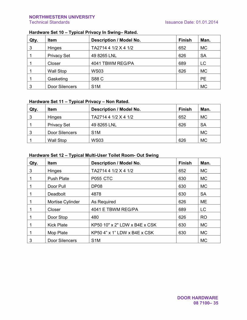
NORTHWESTERN UNIVERSITY Technical Standards Issuance Date: 01.01.2014
DOOR HARDWARE 08 7100– 35
Hardware Set 10 – Typical Privacy In Swing– Rated. Qty. Item Description / Model No. Finish Man. 3 Hinges TA2714 4 1/2 X 4 1/2 652 MC
1 Privacy Set 49 8265 LNL 626 SA
1 Closer 4041 TBWM REG/PA 689 LC
1 Wall Stop WS03 626 MC
1 Gasketing S88 C PE
3 Door Silencers S1M MC
Hardware Set 11 – Typical Privacy – Non Rated. Qty. Item Description / Model No. Finish Man. 3 Hinges TA2714 4 1/2 X 4 1/2 652 MC
1 Privacy Set 49 8265 LNL 626 SA
3 Door Silencers S1M MC
1 Wall Stop WS03 626 MC
Hardware Set 12 – Typical Multi-User Toilet Room- Out Swing Qty. Item Description / Model No. Finish Man. 3 Hinges TA2714 4 1/2 X 4 1/2 652 MC
1 Push Plate P055 CTC 630 MC
1 Door Pull DP08 630 MC
1 Deadbolt 4878 630 SA
1 Mortise Cylinder As Required 626 ME
1 Closer 4041 E TBWM REG/PA 689 LC
1 Door Stop 480 626 RO
1 Kick Plate KP50 10" x 2" LDW x B4E x CSK 630 MC
1 Mop Plate KP50 4” x 1” LDW x B4E x CSK 630 MC
3 Door Silencers S1M MC

NORTHWESTERN UNIVERSITY Technical Standards Issuance Date: 01.01.2014
DOOR HARDWARE 08 7100– 36
Hardware Set 13 – Typical Multi-User Toilet Room- In Swing. Qty. Item Description / Model No. Finish Man. 3 Hinges TA2714 4 1/2 X 4 1/2 652 MC
1 Push Plate P055 CTC 630 MC
1 Door Pull DP08 630 MC
1 Deadbolt 4878 630 SA
1 Mortise Cylinder As Required 626 ME
1 Closer 4041 TBWM REG/PA 689 LC
1 Door Stop 480 626 RO
1 Kick Plate KP50 10" x 2" LDW x B4E x CSK 630 MC
1 Mop Plate KP50 4” x 1” LDW x B4E x CSK 630 MC
3 Door Silencers S1M MC
Hardware Set 14 – Typical Janitor Closet – Out Swing Qty. Item Description / Model No. Finish Man. 3 Hinges TA2714 4 1/2 X 4 1/2 NRP 652 MC
1 Lockset LC 8204 LNL 630 SA
1 Mortise Cylinder As Required 626 ME
1 Closer 4041 SC TBWM 689 LC
1 Kick Plate KP50 10" x 2" LDW x B4E x CSK 630 MC
3 Door Silencers S1M MC
Hardware Set 15 – Typical Storage Room Hazardous Area– Out Swing Qty. Item Description / Model No. Finish Man. 3 Hinges TA2714 4 1/2 X 4 1/2 NRP 652 MC
1 Lockset 76 LC 8204 LNL 630 SA
1 Mortise Cylinder As Required 626 ME
1 Closer 4041 SC TBWM 689 LC
1 Kick Plate KP50 10" x 2" LDW x B4E x CSK 630 MC
3 Door Silencers S1M MC

NORTHWESTERN UNIVERSITY Technical Standards Issuance Date: 01.01.2014
DOOR HARDWARE 08 7100– 37
Hardware Set 16 – Typical Stair Door Qty. Item Description / Model No. Finish Man. 3 Hinges TA2714 4 1/2 X 4 1/2 NRP 26D MC
1 Exit Device 16 43 LC 8813 F ETL 32D SA
1 Mortise Cylinder As Required 626 ME
1 Rim Cylinder As Required 626 ME
1 Closer 4041 TBWM REG/PA AL LC
1 Wall Stop WS03 US26D MC
1 Protection Plate K1050 10" x 2" LDW x B4E x CSK US32D RO
3 Door Silencers S1M MC
Hardware Set 17 – Typical Cross Corridor Pair – Held Open Qty. Item Description / Model No. Finish Man. 6 Hinges TA2714 4 1/2 X 4 1/2 NRP 652 MC
1 Exit Device 12 43 LC 8713 F ETL 630 SA
1 Exit Device 12 43 LC 8710 F ETL-DT 630 SA
1 Rim Cylinder As Required 626 ME
2 Mortise Cylinder As Required 626 ME
2 Closer 4041 TBWM REG/PA 689 LC
2 Magnetic Holder 990 Series 689 RX
1 Kick Plate KP50 10" x 1" LDW x B4E x CSK 630 MC
2 Meeting Stile Set 18041 CNB PE
2 Gasket Set S88 C PE
Hardware Set 18 – Typical Passage – Non Rated
Qty. Item Description / Model No. Finish Man. 3 Hinges TA2714 4 1/2 X 4 1/2 652 MC
1 Passage Set 8215 LNL 626 SA
3 Door Silencers S1M MC
1 Wall Stop WS03 626 MC

NORTHWESTERN UNIVERSITY Technical Standards Issuance Date: 01.01.2014
DOOR HARDWARE 08 7100– 38
Hardware Set 19 – Typical Passage In Swing– Rated Qty. Item Description / Model No. Finish Man. 3 Hinges TA2714 4 1/2 X 4 1/2 652 MC
1 Privacy Set 8215 LNL 626 SA
1 Closer 4041 TBWM REG/PA 689 LC
1 Wall Stop WS03 626 MC
3 Door Silencers S1M MC
Hardware Set 20 – Typical Mechanical Room – Out Swing Qty. Item Description / Model No. Finish Man. 3 Hinges TA2714 4 1/2 X 4 1/2 NRP 652 MC
1 Lockset 86 LC 8204 LNL 630 SA
1 Mortise Cylinder As Required 626 ME
1 Closer 4041 SC TBWM 689 LC
1 Kick Plate KP50 10" x 2" LDW x B4E x CSK 630 MC
3 Door Silencers S1M MC
Hardware Set 21 – Typical Out Swing Laboratory Door Qty. Item Description / Model No. Finish Man. 3 Hinges TA2714 4 ½ X 4 ½ NRP 652 MC
1 Lockset LC 8216 LNL 630 SA
1 Mortise Cylinder As Required 626 ME
3 Door Silencers S1M MC
1 Door Stop 480 626 RO
1 Kick Plate KP50 10" x 2" LDW x B4E x CSK 630 MC

NORTHWESTERN UNIVERSITY Technical Standards Issuance Date: 01.01.2014
DOOR HARDWARE 08 7100– 39
Hardware Set 22 – Typical Out Swing Laboratory Door – Fire Rated Qty. Item Description / Model No. Finish Man. 3 Hinges TA2714 4 ½ X 4 ½ NRP 652 MC
1 Lockset LC 8216 LNL 630 SA
1 Mortise Cylinder As Required 626 ME
1 Closer 4041 TBWM REG/PA 689 LC
3 Door Silencers S1M MC
1 Door Stop 480 626 RO
1 Kick Plate KP50 10" x 2" LDW x B4E x CSK 630 MC
Hardware Set 23 – Typical In-Swing Laboratory Door Qty. Item Description / Model No. Finish Man. 3 Hinges TA2714 4 1/2 X 4 1/2 652 MC
1 Lockset LC 8216 LNL 630 SA
1 Mortise Cylinder As Required 626 ME
3 Door Silencers S1M MC
1 Door Stop 480 626 RO
1 Kick Plate KP50 10" x 2" LDW x B4E x CSK 630 MC
Hardware Set 24 – Typical In-Swing Laboratory Door – Fire Rated Qty. Item Description / Model No. Finish Man. 3 Hinges TA2714 4 1/2 X 4 1/2 652 MC
1 Lockset LC 8216 LNL 630 SA
1 Mortise Cylinder As Required 626 ME
1 Closer 4041 TBWM REG/PA 689 LC
3 Door Silencers S1M MC
1 Door Stop 480 626 RO
1 Kick Plate KP50 10" x 2" LDW x B4E x CSK 630 MC

NORTHWESTERN UNIVERSITY Technical Standards Issuance Date: 01.01.2014
DOOR HARDWARE 08 7100– 40
Hardware Set 25 – Typical Out Swing Electronic Access Door Qty. Item Description / Model No. Finish Man. 2 Hinges TA2714 4 ½ X 4 ½ NRP 652 MC
1 Hinges TA2714 4 ½ X 4 ½ QC6 652 MC
1 Lockset LC 8270/71 LNL 630 SA
1 Mortise Cylinder As Required 626 ME
3 Door Silencers S1M MC
1 Door Stop 480 626 RO
1 Kick Plate KP50 10" x 2" LDW x B4E x CSK 630 MC
Hardware Set 26 – Typical Out Swing Electronic Access Door – Fire Rated Qty. Item Description / Model No. Finish Man. 2 Hinges TA2714 4 ½ X 4 ½ NRP 652 MC
1 Hinges TA2714 4 ½ X 4 ½ QC6 652 MC
1 Lockset LC 8270/71 LNL 630 SA
1 Mortise Cylinder As Required 626 ME
1 Closer 4041 TBWM REG/PA 689 LC
3 Door Silencers S1M MC
1 Door Stop 480 626 RO
1 Kick Plate KP50 10" x 2" LDW x B4E x CSK 630 MC
Hardware Set 27 – Typical In-Swing Electronic Access Door Qty. Item Description / Model No. Finish Man. 2 Hinges TA2714 4 1/2 X 4 1/2 652 MC
1 Hinges TA2714 4 1/2 X 4 1/2 QC6 652 MC
1 Lockset LC 8270/71 LNL 630 SA
1 Mortise Cylinder As Required 626 ME
3 Door Silencers S1M MC
1 Door Stop 480 626 RO
1 Kick Plate KP50 10" x 2" LDW x B4E x CSK 630 MC

NORTHWESTERN UNIVERSITY Technical Standards Issuance Date: 01.01.2014
DOOR HARDWARE 08 7100– 41
Hardware Set 28 – Typical In-Swing Electronic Access Door – Fire Rated Qty. Item Description / Model No. Finish Man. 2 Hinges TA2714 4 1/2 X 4 1/2 652 MC
1 Hinges TA2714 4 1/2 X 4 1/2 QC6 652 MC
1 Lockset LC 8270/71 LNL 630 SA
1 Mortise Cylinder As Required 626 ME
1 Closer 4041 TBWM REG/PA 689 LC
3 Door Silencers S1M MC
1 Door Stop 480 626 RO
1 Kick Plate KP50 10" x 2" LDW x B4E x CSK 630 MC
END OF SECTION

NORTHWESTERN UNIVERSITY Technical Standards Issuance Date: 01.01.2014
DOOR HARDWARE 08 7100– 42
This page intentionally left blank

NORTHWESTERN UNIVERSITY Technical Standards Issuance Date: 01.01.2014
GLAZING 08 8000– 1
DIVISION 8 – OPENINGS
SECTION 08 8000 - GLAZING
1. General: This section outlines the requirements for interior and exterior glazing.
2. Design Criteria:
a. Design to withstand wind loading as specified by applicable code for parts/portions of buildings.
b. Statistical probability of breakage: 8 per 1000, maximum, at 60-second wind load.
c. Low-E glass is preferred at exterior locations.
d. Provide requirements for certification by Contractor, installer, glass fabricator, and/or manufacturer that glass thickness and heat treatment have been selected to provide the strength required to meet specified structural performance requirements.
3. Warranty: Review project specific requirements with NU Project Manager during the design phase.
4. Insulated Glass Units (IGU):
a. Sealed insulating units.
b. Total Thickness: 1 inch, nominal.
c. Review options for low-e coatings, frit patterns, and insulating glass unit construction with the NU Project Manager during the design phase.
5. Closeout Documents – Glazing Schedule: Architect/Engineer shall require that the Contractor provide, at completion of the project, a schedule listing size, type, location, and installation method of all installed glass.
END OF SECTION
NORTHWESTERN UNIVERSITY Technical Standards Issuance Date: 01.01.2014
GLAZING 08 8000– 2
This page intentionally left blank

NORTHWESTERN UNIVERSITY Technical Standards Issuance Date: 01.01.2014
GLAZED ALUMINUM CURTAIN WALL SYSTEM 08 9200– 1
DIVISION 8 – OPENINGS
SECTION 08 9200 – GLAZED ALUMINUM CURTAIN WALL SYSTEM
1. General: This section outlines the requirements for glazed aluminum curtain wall systems for exterior applications:
2. Quality Assurance: Architect shall review the following Contractor Required Quality Assurance and Field Quality Control Testing requirements with the NU Project Manager during the design phase of the project.
a. Engineering Design: Structural engineering shall be performed by a professional engineer licensed in the State of Illinois and employed by the system manufacturer.
b. Mock-up Testing: The following testing is mandatory unless manufacturer can submit acceptable reports of previously performed tests on products equivalent to those to be provided. For standard, stock products, tests performed on the same product for other projects will be accepted.
c. Perform the following tests on a full-size mock-up in the order indicated:
i. Verify air infiltration resistance by testing in accordance with ASTM E 283; report result as cubic feet per minute per unit of measurement indicated, at pressure differential indicated.
ii. Verify water penetration resistance by testing in accordance with ASTM E 331 and AAMA 501.1; report result at pressure differential indicated.
iii. Perform the following tests on mock-up of the size specified by the test method:
1. Verify thermal transmittance by testing in accordance with AAMA 1503.1; report result as U-value (Btu per hour per square foot per degree F).
2. Verify condensation resistance by testing in accordance with AAMA 1503.1; report result as CRF.
iv. Test mock-up(s) in laboratory of testing agency or in manufacturer's plant under supervision of testing agency.
v. Fabricate mock-up(s) from materials matching those proposed for use, using personnel who will perform field installation.
vi. Furnish shop drawing of mock-up to testing agency.
vii. Provide reports certified by the testing agency.
viii. Do not use materials from test mock-up on project.

NORTHWESTERN UNIVERSITY Technical Standards Issuance Date: 01.01.2014
GLAZED ALUMINUM CURTAIN WALL SYSTEM 08 9200– 2
d. Testing Laboratory Qualifications:
i. Independent testing agency
ii. Firm having experience in the testing specified and having the capability to do the testing specified within the time frame required by the contractor, as shown by information supplied as required by ASTM E 699
iii. Firm approved by the University
e. Mock-up: Provide field-constructed mock-ups to serve as the standard of quality for appearance and workmanship to be expected in the completed work.
i. Construct mock-ups of each system, at least 2 stories high by 2 bays wide.
ii. Locate mock-ups where indicated on drawings.
iii. Maintain mock-ups in good condition during construction.
iv. Demolish mock-ups when directed, and remove from site.
3. Field Quality Control:
a. Perform field testing of installed wall for water penetration resistance.
i. Perform testing before covering up of inside face of wall assembly.
ii. Perform AAMA 501.3 ("static") test on the first area of wall to be completed; at least 2 bays wide by 2 stories high.
b. Repair deficiencies discovered by testing and modify installation procedures before installing remainder of wall, to prevent these deficiencies.
c. Perform AAMA 501.2 ("hose") test on at least 2 additional areas of a similar size at higher levels.
i. Repair deficiencies discovered by testing, including similar conditions in areas not tested.
4. Continue to test an additional area and make repairs on entire installation until an area not previously tested tests without deficiencies.
END OF SECTION

NORTHWESTERN UNIVERSITY Technical Standards Issuance Date: 01.01.2014
GYPSUM BOARD 09 2900 – 1
DIVISION 9 – FINISHES
SECTION 09 2900 – GYPSUM BOARD
1. General: This section outlines the requirements for gypsum board systems.
2. Design Considerations:
a. Acoustically Rated Walls: Partitions or assemblies with an STC of 45 or higher.
b. Inspection of Acoustic Insulation and Sealants:
i. Prior to installing drywall on the second side of acoustically rated partitions, Architect/Engineer and/or Northwestern University shall be given the opportunity to confirm proper installation of acoustic products.
3. Cementitious Backer Board: Provide one of the following
a. Durock Cement Board by USG.
b. Wonderboard.
4. Field Constructed Mock-Ups:
a. Review requirements for mock-ups with the NU Project Manager.
b. Prior to installation of drywall systems, erect sample walls to indicate the construction of the following partitions types to confirm details for vapor barrier and acoustically rated partitions.
END OF SECTION

NORTHWESTERN UNIVERSITY Technical Standards Issuance Date: 01.01.2014
GYPSUM BOARD 09 2900 – 2
This page intentionally left blank

NORTHWESTERN UNIVERSITY Technical Standards Issuance Date: 01.01.2014
TILE 09 3000 – 1
DIVISION 9 – FINISHES
SECTION 09 3000 – TILE
1. General: This section outlines the requirements for tile:
2. Design Considerations:
a. Tile Finishes: Review materials, colors, and finishes with NU Project Manager during the design phase.
b. Tile Grouts: Avoid light colored grouts on floors and other horizontal surfaces.
END OF SECTION

NORTHWESTERN UNIVERSITY Technical Standards Issuance Date: 01.01.2014
TILE 09 3000 – 2
This page intentionally left blank

NORTHWESTERN UNIVERSITY Technical Standards Issuance Date: 01.01.2014
RESILIENT FLOORING 09 6500 – 1
DIVISION 9 – FINISHES
SECTION 09 6500 – RESILIENT FLOORING
1. General: This section outlines the requirements for resilient flooring.
2. Design Considerations:
a. Finishes: Review materials, colors, and finishes with NU Project Manager during the design phase.
b. Accessories:
i. Wall Base: Minimum 6-inch height is recommended.
c. Architect shall review the following Contractor requirements with the NU Project Manager and include in the Construction Documents:
i. Initial Cleaning and Sealing: Dry-mop, removing all dust and debris. Clean surface with a neutral cleaner using green pad and floor machine. Clean with a fine abrasive where necessary to remove any stains or cement smears. Clean edges, baseboards, door jambs, and corners using a Doodle Bug pad and holder with a green pad. Pick up all solutions using a wet/dry vacuum. Thoroughly rinse twice with clear water.
ii. Sealing: Where required, apply two coats of water-based sealer and 3 coats of water-based finish using a fine strand rayon mop. Allow a minimum of 45 minutes between coats. All prior coats shall be dry to the touch before any subsequent coats are applied. Apply first coat of sealer and first coat of finish wall to wall. Stop subsequent coats of sealer and finish 1” from baseboards, door jambs, and other vertical edges.
iii. Protection: Cover floor surface, and protect from soiling, staining, marring, scratching, and other damage. Construction traffic, including foot traffic, is strictly prohibited on completed surface. Maintain protection until final completion unless floor is put into service at time of substantial completion.
1. Exceptions: Do not seal static dissipative flooring. Provide visible integral “DO NOT WAX” label in static dissipative flooring tiles.
END OF SECTION

NORTHWESTERN UNIVERSITY Technical Standards Issuance Date: 01.01.2014
RESILIENT FLOORING 09 6500 – 2
This page intentionally left blank

NORTHWESTERN UNIVERSITY Technical Standards Issuance Date: 01.01.2014
TERRAZZO 09 6600 – 1
DIVISION 9 – FINISHES
SECTION 09 6600 – TERRAZZO FLOORING
1. General: This section outlines the requirements for terrazzo flooring:
2. Design Considerations:
a. Materials and Finishes: Review materials, colors, and finishes with NU Project Manager during the design phase.
b. Architect shall review the following contractor requirements with the NU Project Manager and include in the Construction Documents:
i. Initial Cleaning and Sealing: Dry-mop, removing all dust and debris. Clean surface with a neutral cleaner using green pad and floor machine. Clean with a fine abrasive where necessary to remove any stains or cement smears. Clean edges, baseboards, door jambs, and corners using a Doodle Bug pad and holder with a green pad. Pick up all solutions using a wet/dry vacuum. Thoroughly rinse twice with clear water.
ii. Sealing: Apply two coats of water-based sealer and 3 coats of water-based finish using a fine strand rayon mop. Allow a minimum of 45 minutes between coats. All prior coats shall be dry to the touch before any subsequent coats are applied. Apply first coat of sealer and first coat of finish wall to wall. Stop subsequent coats of sealer and finish 1” from baseboards, door jambs, and other vertical edges.
iii. Protection: Cover terrazzo surface, and protect from soiling, staining, marring, scratching, and other damage. Construction traffic, including foot traffic, is strictly prohibited on completed surface. Maintain protection until final completion unless terrazzo is put into service at time of substantial completion.
END OF SECTION

NORTHWESTERN UNIVERSITY Technical Standards Issuance Date: 01.01.2014
TERRAZZO 09 6600 – 2
This page intentionally left blank

NORTHWESTERN UNIVERSITY Technical Standards Issuance Date: 01.01.2014
CARPET 09 6800 – 1
DIVISION 9 – FINISHES
SECTION 09 6800 – CARPET
1. General: This section outlines the requirements for carpet.
2. Design Considerations:
a. Finishes: Review materials, colors, and patterns with NU Project Manager during the design phase.
3. Materials:
a. Glue-Down Installation:
i. Construction: Woven, Unitary, Enhancer/Cushion back.
ii. Yarn: Dupont Antron Nylon or equivalent.
iii. Yarn Weight: 28 oz. minimum.
iv. Yarn color: Yarn dyed.
v. Stitching: 8.0 per inch minimum.
vi. Primary backing: Polypropylene or equivalent.
vii. Secondary backing: Interlocked with face yarn or unitary.
viii. Flammability: Class 1 Radiant Panel Test ASTM E-648.
ix. Smoke Density: 450 or less in a flaming mode ASTM E-622.
x. Static Propensity: Less than 3.5 KVA ATCC -134
xi. Warranty minimum: 10 yr. wear and edge ravel, 15 yr. tuft bind
b. Tackless Installation:
i. Construction: Woven, Tufted with double back unitary, (i.e. sur_lock, duralock, unibond)
ii. Yarn: Dupont Antron Nylon or equivalent.
iii. Yarn Weight: 28 oz. minimum.
iv. Yarn color: Yarn dyed.
v. Stitching: 8.0 per inch minimum.
vi. Primary backing: Polypropylene or equivalent.

NORTHWESTERN UNIVERSITY Technical Standards Issuance Date: 01.01.2014
CARPET 09 6800 – 2
vii. Secondary backing: : Polypropylene or equivalent.
viii. Flammability: Class 1 Radiant Panel Test ASTM E-648.
ix. Smoke Density: 450 or less in a flaming mode ASTM E-622.
x. Static Propensity: Less than 3.5 KVA ATCC -134
xi. Warranty minimum: 10 yr. wear and edge ravel/no zipper, 15 yr. tuft bind
c. Provide 38 oz. minimum yarn weight at steps and classroom risers with rubber nosings.
d. Elevators: Review special fire retardant code requirements for elevators.
e. Require manufacturer to certify, in writing, that product is appropriate for the intended use.
2. Installation:
a. Perform installation in accordance with manufacturer's instructions, except where more stringent requirements are shown or specified, and except where project conditions require extra precautions or provisions to ensure satisfactory performance of the work.
b. Seams: Using carpet manufacturer's recommended procedures, form secure seams capable of sustaining expected stresses without failure for the life of the installation.
a. Provide samples and seaming diagrams for all areas before proceeding with carpet installation.
END OF SECTION

NORTHWESTERN UNIVERSITY Technical Standards Issuance Date: 01.01.2014
PAINING 09 9000 – 1
DIVISION 9 – FINISHES
SECTION 099 000 – PAINTING
1. General: This section outlines the requirements for interior and exterior painting.
2. Design Considerations:
a. Colors: Northwestern has standardized the following Benjamin Moore white paint colors on campus. The intent is to provide a range of standard white colors that architects can specify.
i. Decorators White
ii. Bone White
iii. White Dove
iv. China White
v. Linen White
vi. Super White for ceilings and soffits.
3. Submittals: Provide for each coating system, color, and texture; apply to representative substrate samples. Prepare samples to show bare, prepared surface and each successive coat. Label each sample with coating name manufacturer type and color, name and/or number.
4. Manufacturer: Top line products of Benjamin Moore & Company. Pratt & Lambert may be used for wood finishing products.
a. Colors: For multi-coat systems, apply each coat using a successively darker tint or shade, unless approved otherwise.
b. Top coat colors: As indicated in color schedule.
5. Prime Coats:
a. Thinned top coats are not permitted as primers.
b. Field apply bottom coats scheduled except where the contract documents require shop coating of ferrous metals. Ferrous metals that have not been shop primed shall be field primed promptly after arrival at the site or shall be stored away from the effects of weather. Repair and retouch damaged prime coats using approved, compatible primer.
c. Primers for Wood and Wood Products: Apply first coat to wood upon receipt at the site and before wood is exposed to sun or rain.

NORTHWESTERN UNIVERSITY Technical Standards Issuance Date: 01.01.2014
PAINING 09 9000 – 2
6. Schedule of Coatings for Interior Non-Traffic Surfaces:
a. Gypsum Wallboard & Plaster: Latex, eggshell on walls, flat on ceilings.
b. Concrete Masonry Units - Filled Finish: As scheduled, Latex, satin or Tile-like epoxy, low gloss.
c. Concrete and Masonry: As scheduled, Latex, satin or Tile-like epoxy, low gloss.
d. Wood: As scheduled, Latex, satin. Varnish, satin (stained wood).
e. Ferrous Metal: Latex, satin, low gloss.
f. Galvanized Metal: Latex, gloss.
g. In extraordinary cases, such as very high use doors or windows, or in laboratories, oil base or epoxy may be necessary. Request University approval prior to specifying.
7. Schedule of Coatings for Interior Traffic Surfaces:
a. Concrete: Epoxy floor enamel.
b. Wood: As scheduled, Alkyd/urethane floor enamel, gloss. Varnish, gloss (stained wood).
8. Schedule of Coatings for Exterior Surfaces:
a. Concrete Masonry Units - Filled Finish: Latex.
b. Ferrous Metal: Latex, gloss.
c. Galvanized Metal: Latex, gloss.
9. Project Closeout:
a. Schedule of Installed Coatings: At the completion of the project, Architect shall require that Contractor provide a complete listing of all coatings. Include manufacturer, product name, primer and top coats, number of coats, application methods and a detailed diagram of colors by location.
END OF SECTION

NORTHWESTERN UNIVERSITY Technical Standards Issuance Date: 01.01.2014
VISUAL DISPLAY SURFACES 10 1100 – 1
DIVISION 10 – SPECIALTIES
SECTION 10 1100 – VISUAL DISPLAY SURFACES
1. General: This section outlines the requirements for visual display surfaces.
2. Design Considerations: Review project specific requirements including size, location, and types of visual display surfaces with the NU Project Manager during the design phases of the project.
3. Basis of Design Manufacturers:
a. Marker Boards: Provide Claridge Co. LCS writing surface.
END OF SECTION

NORTHWESTERN UNIVERSITY Technical Standards Issuance Date: 01.01.2014
VISUAL DISPLAY SURFACES 10 1100 – 2
This page intentionally left blank

NORTHWESTERN UNIVERSITY Technical Standards Issuance Date: 01.01.2014
TOILET COMPARTMENTS 10 2113 – 1
DIVISION 10 – SPECIALTIES
SECTION 10 2113 – TOILET COMPARTMENTS
1. General:
a. This section outlines the requirements for toilet compartments.
b. NU preference is solid plastic, recycled, high-density polyethylene (HDPE) floor mounted, overhead braced (floor to ceiling) units. Ceiling hung units are not preferred.
i. Basis of Design Manufacturer: Santana Solid Plastic Products.
c. Other products are acceptable pending review with NU Project Manager.
2. Materials:
a. General: Materials shall be scratch and graffiti resistant.
b. Steel Sheets for Baked Enamel Finish: ASTM A 591, Class C, galvanized bonderized, of following minimum thickness.
i. Pilasters (overhead braced): 20 gauge.
ii. Pilasters (unbraced): 16 gauge.
iii. Panels and Screens: 20 gauge.
iv. Doors: 22 gauge.
c. Core Material for Metal Partitions: Manufacturer's standard sound deadening honey comb of impregnated Kraft paper, in thickness to provide finished dimension of 1" minimum for doors, panels, and screens, 1 1/4" minimum for pilasters.
d. Pilaster Shoes: ASTM A 167, Type 302/304 stainless steel, not less than 3" high, 20 gauge, finished to match hardware.
e. Hardware:
i. Hinges: Provide continuous self-closing hinges.
ii. Material: Stainless steel.
3. Fabrication:
a. General: Provide floor mounted, overhead braced units. Furnish standard doors, panels, screens, and pilasters fabricated for partition system, unless otherwise indicated. Furnish units with cutouts, drilled holes, and internal

NORTHWESTERN UNIVERSITY Technical Standards Issuance Date: 01.01.2014
TOILET COMPARTMENTS 10 2113 – 2
reinforcement to receive partition mounted hardware, accessories, and grab bars, as indicated. Furnish continuous, full-height bracket at rear walls.
b. Door Dimensions: Unless otherwise indicated, furnish 24" wide in-swinging doors for ordinary toilet stalls and 32" wide (clear opening) out-swinging doors at stalls equipped for use by handicapped.
c. Metal Toilet Partitions: Pressure laminate seamless face sheets to core material and seal edges with continuous interlocking strip or with lapped and formed edges. Weld edges and corners, with exposed welds ground smooth.
a. Finishes: Baked Enamel Finish: Clean galvanized steel surfaces after fabrication and before application of enamel coating system, to remove processing compounds, oils, and other contaminants. Prime metal with baked on rust inhibitive primer. Apply two coats of thermosetting enamel finish, applied by electrostatic process, and baked in accordance with paint manufacturer's instructions.
END OF SECTION

NORTHWESTERN UNIVERSITY Technical Standards Issuance Date: 01.01.2014
OPERABLE PARTITIONS 10 2226 – 1
DIVISION 10 – SPECIALTIES
SECTION 10 2226 - OPERABLE PARTITIONS
1. General: This section outlines the requirements for toilet compartments.
2. Design Considerations:
a. When operable partitions are required, provide STC 52 or higher.
b. Review project specific requirements with the NU Project Manager during the design phase of the project.
END OF SECTION

NORTHWESTERN UNIVERSITY Technical Standards Issuance Date: 01.01.2014
OPERABLE PARTITIONS 10 2226 – 2
This page intentionally left blank

NORTHWESTERN UNIVERSITY Technical Standards Issuance Date: 01.01.2014
TOILET AND BATH ACCESSORIES 10 2800 – 1
DIVISION 10 – SPECIALTIES
SECTION 10 2800 – TOILET AND BATH ACCESSORIES
1. General: This section outlines the requirements for toilet compartments.
2. Design Considerations: Architect shall review project requirements for toilet and bath accessories with the NU Project Manager during the design phases.
3. Products:
a. Typically, the standard paper towel dispensers, soap dispensers, toilet paper dispensers, and feminine napkin dispensers are provided by Northwestern for installation by the Contractor.
b. Typically, the grab bars, mirrors, feminine napkin disposals, and other accessories shall be furnished and installed by the Contractor.
c. Review project requirements and coordinate electrical requirements for any electrical accessories.
END OF SECTION

NORTHWESTERN UNIVERSITY Technical Standards Issuance Date: 01.01.2014
TOILET AND BATH ACCESSORIES 10 2800 – 2
This page intentionally left blank

NORTHWESTERN UNIVERSITY Technical Standards Issuance Date: 01.01.2014
PROJECTION SCREENS 11 5213 – 1
DIVISION 11 – EQUIPMENT
SECTION 11 5213 – PROJECTION SCREENS
1. General: This section outlines the requirements for projection screens that are provided as part of the project.
2. Design Considerations:
a. Projection screens, both manual and motorized, shall typically be provided as part of the base bid scope of work and not part of the furnishings, fixtures and equipment (FF&E).
b. Architect/Engineer shall review options with the NU Project Manager during the design phase of the project and coordinate power and/or data requirements.
3. Quality Assurance: Obtain each type of projection screen required from a single manufacturer as a complete unit, including necessary mounting hardware and accessories.
4. Projection Screen Surfaces, General: Obtain screens manufactured from mildew and flame resistant fabric of type indicated for each type of screen specified and complying with the following requirements:
a. Normally provide matte white viewing surface with minimum gain characteristics complying with FS GG S 00172D (1) for Type A screen surface.
b. For larger rooms provide glass beaded viewing surface with minimum gain characteristics complying with FS GG S 00172D (1) for Type C screen surface.
5. Electrically Operated Front Projection Screens: Single Station Control: Three position, UL listed control switch for each screen with metal device box and cover plate for flush wall mounting and for connection to 120 V a/c. power supply.
a. Motor Operated Screens with Automatic Closure: Units designed and fabricated for recessed installation in ceiling with bottom of case composed of two panels fully enclosing screen and wiring compartments, one panel hinged and activated by operation of screen to open and close automatically when screen is lowered and fully raised and the other panel removable or operable for access to interior of case.
b. Offset mount bottom panels to case in position where their bottom surfaces will align flush with finished surface of adjoining ceiling and the bottom edges of case surrounding panels will be recessed by the depth of, and concealed behind, overlapping ceiling finish.
6. Manually Operated Front Projection Screens: Provide case, screen, mounting accessories and other components as required for a complete installation and complying with descriptive requirements indicated below.

NORTHWESTERN UNIVERSITY Technical Standards Issuance Date: 01.01.2014
PROJECTION SCREENS 11 5213 – 2
a. Spring Roller Operated Projection Screens: Units designed and fabricated for wall or ceiling installation and complying with the following requirements:
b. Screen Case: Fabricated in one piece from not less than 22 gage steel with flat back design, vinyl covered or baked enamel finish, and end caps with integral roller brackets and furnished with universal mounting brackets in finish matching end caps to enable attachment to wall or ceiling.
END OF SECTION

NORTHWESTERN UNIVERSITY Technical Standards Issuance Date: 01.01.2014
WINDOW TREATMENTS 12 2000– 1
DIVISION 12 – FURNISHINGS
SECTION 12 2000 – WINDOW TREATMENTS
1. General: This section outlines the requirements for window screens that are provided as part of the project.
2. Design Considerations:
a. Window treatments shall typically be provided as part of the base bid scope of work and not part of the furnishings, fixtures and equipment (FF&E).
b. Architect/Engineer shall review options with NU Project Manager during the design phase of the project and coordinate power requirements for motorized shades.
3. Horizontal Blinds:
a. General: Head rail and blinds shall conform to shape of window. Bottom rail, tubular steel, designed to withstand twisting or sagging. Contour top surface to match slat curvature, with flat or slightly curved bottom. Close ends with metal or plastic end caps of same color as rail. Finish rail in same color as slats.
b. Slats: Spring tempered aluminum (louver blades), rounded corners with forming burrs removed.
c. Tilting Mechanism: Assembly including disengaging worm and gear mechanism to eliminate overdrive, low friction gear tilter, drum and cradle at each ladder, tilt rod, tape clips, and grommet guides to prevent wear on ladder and cords; designed to hold slats at any angle and prevent movement of slats due to vibration, operated as follows:
d. Wand Operator: Detachable clear plastic wand, of proper length to suit blind installation, detachable without tools by raising locking sleeve.
e. Lifting Mechanism: Crash-proof cord locks with cord separators and braided polyester or nylon lift cords with tassels at ends. Size cord to suit blind type. Include self-aligning cord equalizers designed to maintain horizontal blind position.
f. Installation Brackets: Designed to facilitate removal of head channels. Design brackets to support safely the weight of blind assemblies plus forces applied to operate blinds.
END OF SECTION

NORTHWESTERN UNIVERSITY Technical Standards Issuance Date: 01.01.2014
WINDOW TREATMENTS 12 2000– 2
This page intentionally left blank

NORTHWESTERN UNIVERSITY Technical Standards Issuance Date: 01.01.2014
ENTRANCE FLOOR GRILLES 12 4816– 1
DIVISION 12 – FURNISHINGS
SECTION 12 4816 – ENTRANCE FLOOR GRILLES
1. General: This section outlines the requirements for entrance floor grilles.
2. Design Criteria:
a. Foot grilles and frames shall be designed to support a uniform distributed load of at least 200 pounds per square foot.
3. Quality Assurance: Single Source Responsibility: Obtain foot grilles and frames from one source from a single manufacturer.
4. Aluminum Foot Grilles: Provide manufacturer's standard extruded aluminum foot grille with top surfaced tread rails. Framing members and tread rail material, aluminum finish, tread top surface, and tread rail spacing as indicated.
a. Provide frames for foot grilles of same material as other framing members with finish to match tread rails.
b. Aluminum: Extruded aluminum, ASTM B 221, alloy 6061 T6 for tread rails and keylock, where used; alloy 6063 T5 or T6 for framing and connecting members.
c. Tread Rail Spacing: 1-1/2 inches on center with 1/8-inch to 3/16-inch wide openings between treads.
d. Aluminum Finish: Natural mill finish.
e. Top Surface: Fusion bonded level cut pile nylon carpet insert; DuPont "Antron III" filament, 1/4 inch high, 28 oz. per sq. yd.
5. Support System: Provide cushion support system.
6. Drainage Pit Applications: Provide special deep pit frame and support extrusion system with intermediate support beams, sized and spaced as recommended by manufacturer for indicated spans and equipped with vinyl support cushions.
a. Provide 16 gage stainless steel or 0.060 inch thick aluminum pit liner for each entrance mat unit, with 2 inch IPS floor drain. Coat bottom of aluminum pan with zinc chromate paint. Provide joint sealant between the concrete slab and metal pan.
END OF SECTION

NORTHWESTERN UNIVERSITY Technical Standards Issuance Date: 01.01.2014
ENTRANCE FLOOR GRILLES 12 4816– 2
This page intentionally left blank

NORTHWESTERN UNIVERSITY Technical Standards Issuance Date: 01.01.2014
ELECTRIC TRACTION ELEVATORS 14 2100 – 1
DIVISION 14 – CONVEYING EQUIPMENT
SECTION 14 2100 – ELECTRIC TRACTION ELEVATORS
1. General:
a. Northwestern requires a third party, independent elevator consultant for assistance with the design and reviews related to elevators and conveying equipment.
b. Elevators must be specified by a licensed engineer in compliance with all applicable codes.
c. Elevator consultant to include Construction Administration during the construction phase. Services shall include a minimum of three (3) site meetings with report or ideally, bi-monthly site meetings throughout elevator construction.
1. Submittals:
a. Maintenance Manuals: Three (3) Bound manuals with operating and maintenance instructions, parts listing, recommended parts inventory listing, purchase source listing for major and critical components, emergency instructions, and similar information.
b. Provide complete wiring diagrams to be left on-site, secured in elevator machine room.
c. Certificates and Permits: Provide University with copies of all inspection/acceptance certificates and operating permits as required by governing authorities to allow normal, unrestricted use of elevator.
2. Keys:
a. Contractor to provide Northwestern with a minimum of three (3) sets of all keys at the time of acceptance.
3. Quality Assurance:
a. Installer Qualifications: Elevator contractor must be member of Local 2 elevator union in good standing, and has completed several successful elevator installations similar in material, design, and extent as what is being specified for the Project.
4. Maintenance Service:
a. Architect/Engineer shall review maintenance service agreements for existing and/or new elevators.
b. Initial Maintenance Service: Elevator specification shall require the Contractor to Provide full maintenance service by skilled, competent employees of the Elevator

NORTHWESTERN UNIVERSITY Technical Standards Issuance Date: 01.01.2014
ELECTRIC TRACTION ELEVATORS 14 2100 – 2
Installer for period of twelve (12) months following Date of Substantial Completion.
i. Include monthly preventive maintenance performed during normal working hours.
ii. Include repair or replacement of worn or defective parts or components and lubricating, cleaning, and adjusting as required for proper elevator operation in conformance with specified requirements.
iii. Include 24 hours per day, 7 days per week emergency callback service.
iv. Exclude only repair or replacement due to misuse, abuse, accidents, or neglect caused by persons other than Installer's personnel.
5. Elevator Characteristics Summary:
a. Capacity Exclusive of Car: Minimum 3500 lbs.
b. Rated Speed: Per elevator consultant specification, varies with size/use..
c. Cab Inside Size: Minimum 6'-8" wide x 5'-5" deep.
d. Cab Height: Minimum 7’- 2”; preferred 8'-0", inside clear..
e. Door Operation: Minimum Single slide, left hand opening, 3'-6" wide x 7'-0" high.
f. Power Supply: 208 volts, 3 phase, 3 wires, 60 hz, 40 H.P., AC, verify with sources available.
g. Lighting Supply: 120 volts, 15 amps, single phase 60 hz, AC.
h. Lighting: LED.
i. Microprocessor electronics.
j. Controllers: Controllers shall be Galaxy (GAL), MCE, Otis and/or other non-proprietary manufacturer per review and approval by NU Project Manager.
k. Cabling: Provide additional twisted pair and coax for future security or control use as per Project Manager. Millennium requires 5 sets twisted pair; cameras 1 coax each.
l. Hoistway: Provide a sump pump and sump pump basin if required by applicable codes and/or engineer/architect/project manager review.
6. Signal Equipment:
a. Telephone / Intercom: Provide rough in for “hands free” intercom in car, contained in flush mounted cabinet. Elevator contractor to set up phone to accept direct ring down to Northwestern University Police (NUPD). Northwestern will

NORTHWESTERN UNIVERSITY Technical Standards Issuance Date: 01.01.2014
ELECTRIC TRACTION ELEVATORS 14 2100 – 3
provide correctly activated phone jack & patch cord. If required by applicable code, provide a fireman's telephone cabinet or fireman's telephone jack in main elevator lobby.
b. Alarm System: Provide security system as required per all applicable codes.
c. Vandal Resistant Signal Equipment: Adams Survivor Plus:
i. Car control stations.
ii. Car position indicators.
iii. Hall push button stations.
iv. Hall lanterns.
d. Hall Lanterns must be easily visible throughout the elevator lobby, as per code.
7. Personal Protective Devices:
a. General: Provide personal protective devices as per all applicable codes and elevator consultant.
b. Handrails: Coordinate installation of handrails with interior panels.
c. Door Edge Protective Device: Provide retractable edge shoe on leading edges of elevator entrance doors that causes doors to stop and reopen upon contacting an obstruction in entrance, per all applicable codes.
d. Photo Eye Detection Device: Provide electronic photo eye device with timed cutout, projecting dual light beams across car entrance at 5 inch and 29 inch heights, that when interrupted will cause closing doors to stop and reopen. Provide keyed switch in car operating panel or toggle switch in service cabinet for disconnecting photo eye protective device, per all applicable codes.
8. Passenger Hoistway Entrances:
a. Enameled Frames: Formed steel with manufacturer's standard primed-for-paint finish.
b. Stainless Steel Frames: Formed steel with brushed finish.
c. Aluminum Sills: Extruded aluminum, with grooved surface, 1/4 inch thickness, mill finish.
9. Passenger Cab Details:
a. General: Elevator cab to be specified to full compliance with all applicable codes.

NORTHWESTERN UNIVERSITY Technical Standards Issuance Date: 01.01.2014
ELECTRIC TRACTION ELEVATORS 14 2100 – 4
b. Rubber flooring or terrazzo is preferred over carpet by Northwestern. Review options for carpet and associated replacement carpet or attic stock with NU Project Manager.
c. Ceilings must be completely accessible from the car top as per applicable codes.
d. Handrails to be removable (but tamper proof) from inside the cab.
e. Provide scratch and graffiti-proof wall panels. Review options that include stainless steel or plastic laminate with the NU Project Manager.
f. Provide passenger cab protection blankets for each side of elevator cab.
g. Provide blanket hooks at perimeter.
h. Provide convenience electrical outlet.
10. Field Quality Control:
a. Acceptance Testing: Elevator may not be turned over before passing acceptance tests as required and recommended by Code and by the authority having jurisdiction (AHJ).
b. Operating Tests: As required by the AHJ and all applicable codes.
11. Demonstration and Training:
a. Contractor shall instruct Northwestern personnel in proper use, operations, and daily maintenance of elevators. Review emergency provisions, including emergency access and procedures to be followed at time of failure in operation and other building emergencies. Train University's personnel in normal procedures to be followed in checking for sources of operational failures or malfunctions. Confer with Northwestern on requirements for a complete elevator maintenance program.
b. Contractor shall make a final check of each elevator operation with University's personnel present and just prior to date of Substantial Completion. Determine that control systems and operating devices are functioning properly. Contractor must provide Northwestern a copy of all inspection reports and complete paperwork to provide Northwestern the State Elevator tag before closing the project.
c. Contractor to check that software is updated at end of 12 month warranty period and also run diagnostics to check that no boards are failing. If needed, replace faulty boards under warranty.
END OF SECTION

NORTHWESTERN UNIVERSITY Technical Standards Issuance Date: 01.01.2014
HYDRAULIC ELEVATORS 14 2400– 1
DIVISION 14 – CONVEYING EQUIPMENT
SECTION 14 2400 – HYDRAULIC ELEVATORS
1. General:
a. Northwestern requires a third party, independent elevator consultant for assistance with the design and reviews related to elevators and conveying equipment.
b. Elevators must be specified by a licensed engineer in compliance with all applicable codes.
c. Elevator consultant to include Construction Administration during the construction phase. Services shall include a minimum of three (3) site meetings with report or ideally, bi-monthly site meetings throughout elevator construction.
1. Submittals:
a. Maintenance Manuals: Three (3) Bound manuals with operating and maintenance instructions, parts listing, recommended parts inventory listing, purchase source listing for major and critical components, emergency instructions, and similar information.
b. Provide complete wiring diagrams to be left on-site, secured in elevator machine room.
c. Certificates and Permits: Provide University with copies of all inspection/acceptance certificates and operating permits as required by governing authorities to allow normal, unrestricted use of elevator.
2. Keys:
a. Contractor to provide Northwestern with a minimum of three (3) sets of all keys at the time of acceptance.
3. Quality Assurance:
a. Installer Qualifications: Elevator contractor must be member of Local 2 elevator union in good standing, and has completed several successful elevator installations similar in material, design, and extent as what is being specified for the Project.
4. Maintenance Service:
a. Architect/Engineer shall review maintenance service agreements for existing and/or new elevators.
b. Initial Maintenance Service: Elevator specification shall require the Contractor to Provide full maintenance service by skilled, competent employees of the Elevator

NORTHWESTERN UNIVERSITY Technical Standards Issuance Date: 01.01.2014
HYDRAULIC ELEVATORS 14 2400– 2
Installer for period of twelve (12) months following Date of Substantial Completion.
i. Include monthly preventive maintenance performed during normal working hours.
ii. Include repair or replacement of worn or defective parts or components and lubricating, cleaning, and adjusting as required for proper elevator operation in conformance with specified requirements.
iii. Include 24 hours per day, 7 days per week emergency callback service.
iv. Exclude only repair or replacement due to misuse, abuse, accidents, or neglect caused by persons other than Installer's personnel.
5. Elevator Characteristics Summary:
a. Capacity Exclusive of Car: Minimum 3500 lbs.
b. Rated Speed: 125 fpm or as per elevator specification.
c. Cab Inside Size: Minimum 6'-8" wide x 5'-5" deep.
d. Cab Height: Minimum 7’-2”; preferred 8'-0", inside clear.
e. Door Operation: Single slide, left hand opening, 3'-6" wide x 7'-0" high.
f. Power Supply: 208 volts, 3 phase, 3 wires, 60 hz, 40 H.P., AC, verify with sources available.
g. Lighting Supply: 120 volts, 15 amps, single phase 60 hz, AC
h. Machine Location: Non- basement location preferred.
i. Microprocessor electronics.
j. Controllers: Controllers shall be Galaxy (GAL), MCE, Otis and/or other non-proprietary manufacturer per review and approval by NU Project Manager.
k. Cabling: Provide additional twisted pair and coax for future security or control use as per Project Manager. Millennium requires 5 sets twisted pair; cameras 1 coax each.
l. Hoistway: Provide a sump pump and sump pump basin if required by applicable codes and/or engineer/architect/project manager review.
6. Signal Equipment:
a. Telephone / Intercom: Provide rough in for “hands free” intercom in car, contained in flush mounted cabinet. Elevator contractor to set up phone to accept direct ring down to Northwestern University Police (NUPD). Northwestern will

NORTHWESTERN UNIVERSITY Technical Standards Issuance Date: 01.01.2014
HYDRAULIC ELEVATORS 14 2400– 3
provide correctly activated phone jack & patch cord. If required by applicable code, provide a fireman's telephone cabinet or fireman's telephone jack in main elevator lobby.
b. Alarm System: Provide security system as required per all applicable codes.
c. Vandal Resistant Signal Equipment: Adams Survivor Plus:
i. Car control stations.
ii. Car position indicators.
iii. Hall push button stations.
iv. Hall lanterns.
d. Hall Lanterns must be easily visible throughout the elevator lobby.
7. Personal Protective Devices:
a. Handrails: Coordinate installation of handrails with interior panels.
b. Door Edge Protective Device: Provide as required per all applicable codes.
c. Photo Eye Detection Device: Provide as required per all applicable codes.
8. Passenger Hoistway Entrances:
a. Enameled Frames: Formed steel with manufacturer's standard primed-for-paint finish.
b. Stainless Steel Frames: Formed steel with brushed finish.
c. Aluminum Sills: Extruded aluminum, with grooved surface, 1/4 inch thickness, mill finish.
9. Passenger Cab Details:
a. General: Elevator cab to be specified to full compliance with all applicable codes.
b. Rubber flooring or terrazzo is preferred over carpet by Northwestern. Review options for carpet and associated replacement carpet or attic stock with NU Project Manager.
c. Ceilings must be completely accessible from the car top as per applicable codes.
d. Handrails to be removable (but tamper proof) from inside the cab.
e. Provide scratch and graffiti-proof wall panels. Review options that include stainless steel or plastic laminate with the NU Project Manager.
NORTHWESTERN UNIVERSITY Technical Standards Issuance Date: 01.01.2014
HYDRAULIC ELEVATORS 14 2400– 4
f. Provide passenger cab protection blankets for each side of elevator cab for each elevator. Provide blanket hooks at perimeter of each elevator.
g. Provide convenience electrical outlet in each elevator.
10. Installation of Elevator System:
a. General: Provide “holeless” hydraulic system where possible. When not possible, provide as follows:
b. Excavation for Jack: Drill excavation in each elevator pit to accommodate installation of plunger cylinder unit; comply with applicable requirements of Division 2 "Excavation" section.
c. Install casings with waterproof seals at pit floor and with waterproof, high pressure seal at bottom of casings.
d. Provide a second (inner) casing with welded waterproof, high pressure seal at bottom and set inside outer (initial) casing.
e. Corrosion Protection: The inside of the cylinder shall be treated with rust preventative and the outside with a suitable heavy duty service bitumastic or tape wrap.
11. Field Quality Control:
a. Acceptance Testing: Elevator may not be turned over before passing acceptance tests as required and recommended by Code and by the authority having jurisdiction (AHJ).
b. Operating Tests: As required by the AHJ and all applicable codes.
12. Demonstration and Training:
a. Contractor shall instruct University personnel in proper use, operations, and daily maintenance of elevators. Review emergency provisions, including emergency access and procedures to be followed at time of failure in operation and other building emergencies. Train University's personnel in normal procedures to be followed in checking for sources of operational failures or malfunctions. Confer with University on requirements for a complete elevator maintenance program.
b. Contractor shall make a final check of each elevator operation with University's personnel present and just prior to date of Substantial Completion. Determine that control systems and operating devices are functioning properly. Contractor must provide Northwestern a copy of all inspection reports and complete paperwork to provide Northwestern the State Elevator tag before closing the project.
c. Contractor to check that software is updated at end of 12 month warranty period and also run diagnostics to check that no boards are failing. If needed, replace faulty boards under warranty.

NORTHWESTERN UNIVERSITY Technical Standards Issuance Date: 01.01.2014
HYDRAULIC ELEVATORS 14 2400– 5
d. Hydraulic Elevators are included in the University's Spill Response Plan. All new elevators must be catalogued with the FMO Staff Engineer.
END OF SECTION

NORTHWESTERN UNIVERSITY Technical Standards Issuance Date: 01.01.2014
HYDRAULIC ELEVATORS 14 2400– 6
This page intentionally left blank

NORTHWESTERN UNIVERSITY Technical Standards Issuance Date: 01.01.2014
GENERAL FIRE SUPPRESSION REQUIREMENTS 21 0000 - 1
DIVISION 21 – FIRE SUPPRESSION
SECTION 21 0000 – GENERAL FIRE SUPPRESSION REQUIREMENTS
1. General:
a. This section outlines general requirements for fire suppression systems.
b. Section 28 3113 also contains design requirements for automatic sprinkler systems.
2. Design Criteria:
a. NFPA Standards 13 and 14 provide the basic design guidance for automatic sprinkler systems. Modifications and clarifications that follow must be incorporated into the design and specifications.
i. As a minimum, each floor of a building shall be a separate automatic sprinkler zone coordinated with the fire alarm system.
ii. Automatic sprinkler zones shall be coordinated with the smoke control systems. In no case shall parts of one automatic sprinkler zone be contained in more than one smoke control zone.
iii. When sprinklers are specified, provide a combined automatic sprinkler and standpipe system.
1. On the Evanston campus pressure for hose steam requirements in "low rise" buildings is provided by the responding fire department. Fire pumps are to be provided where insufficient pressure is available for automatic sprinkler demands and "high rise" buildings. For buildings equipped with fire pumps, the pump shall provide both hose stream and automatic sprinkler demands.
iv. The automatic sprinkler design criterion applies to wet pipe systems. Increase the area of application in accordance with NFPA Standard 13 for dry systems.
v. Occupancy classification definitions shall follow NFPA Standard 13. The Room Design Method in NFPA Standard 13 shall not be used to reduce the area of application for each classification below. However, the use of the Special Design Methods is permitted and should be used where applicable.
vi. On the Chicago campus, the Chicago Building Code shall be consulted for deviations from NFPA standards.
b. The following occupancies shall be reviewed with the NU Project Manager and the University’s Office of Risk Management to determine the sprinkler system design basis for the following areas and vaults:

NORTHWESTERN UNIVERSITY Technical Standards Issuance Date: 01.01.2014
GENERAL FIRE SUPPRESSION REQUIREMENTS 21 0000 - 2
i. Multiple purpose areas that may be used for exhibits.
ii. Storage areas over 12 feet high.
iii. Storage for tires, rolled paper, Group A plastics, or unusual materials of any height.
iv. Vaults for liquids, gases, or wastes.
END OF SECTION

NORTHWESTERN UNIVERSITY Technical Standards Issuance Date: 01.01.2014
AUTOMATIC FIRE SPRINKLER SYSTEMS 21 1314 - 1
DIVISION 21 – FIRE SUPPRESSION
SECTION 21 1314 – AUTOMATIC FIRE SPRINKLER SYSTEMS
1. General: This section outlines general requirements for automatic fire sprinkler systems.
2. Design Considerations:
a. Siamese connections shall be arranged to supply both the automatic sprinkler and standpipe systems.
b. Fire pumps shall include a valved bypass city loop and a valved connection to an outside test header. Valve arrangements shall be such that the fire pumps can be isolated during testing with the city loop remaining in service.
c. Dry pipe systems to be utilized:
i. Areas exposed to outdoor temperatures, eg pedestrian bridges between buildings, loading docks, etc.
ii. Areas sensitive to water, eg document storage, museums/art galleries, etc.
d. Dry pipe valves should be provided with a dedicated tank-type air compressor. In no case shall dry pipe valves be connected to an HVAC control air compressor. Dedicated air compressors must be connected to the emergency power system.
e. Drains from automatic sprinkler system equipment (dry pipe valves, flow test valves, RPZ backflow preventers) shall be piped to a floor drain capable of handling the expected maximum discharge for at least two minutes.
f. Quick response automatic sprinklers are required in offices, classrooms, hallways, assembly areas, atriums, sleeping rooms, dining rooms, and most laboratory areas. Ordinary response heads shall be used in storage areas, mechanical rooms, janitor closets, and areas where special coated sprinkler heads are required. Temperature ratings shall be the maximum expected ceiling temperature.
g. A water flow alarm shall be installed in each automatic sprinkler zone at the main water supply entrance, and at the supply connection to each vertical combined automatic sprinkler and standpipe riser.
h. Valve supervisory switches shall be provided for each point where the water supply to the system or parts of the system can be shutoff. Valves grouped at a common location can be combined into the same zone to a maximum of five. In no case shall control valves be concealed. External tamper switches or external wired tamper switches are required. Butterfly sectional and floor control valves are preferred.

NORTHWESTERN UNIVERSITY Technical Standards Issuance Date: 01.01.2014
AUTOMATIC FIRE SPRINKLER SYSTEMS 21 1314 - 2
i. Architect/Engineer of record will be required to meet with the Authority Having Jurisdiction (AHJ) for either Chicago or Evanston Campus.
j. Siamese connections shall be of the flush type having a polished chrome plated finish. Lettering shall indicate dual service.
i. On the Evanston campus, provide a weatherproof visual fire alarm signal device above the Siamese connection along with a weatherproof box for a future audible device.
k. Sprinkler heads located in ceiling tiles should be centered in the tile unless the head can otherwise be aesthetically located.
END OF SECTION

NORTHWESTERN UNIVERSITY Technical Standards Issuance Date: 01.01.2014
DRY CHEMICAL SUPPRESSION SYSTEM 21 2400 - 1
DIVISION 21 – FIRE SUPPRESSION
SECTION 21 2400 –CHEMICAL SUPPRESSION SYSTEMS
1. General: This section outlines general requirements for chemical suppression systems.
2. Design Considerations:
a. Dry chemical suppression systems are preferred except in kitchens where wet chemical systems have typically replaced dry chemical systems. Review specific requirements with the NU Project Manager.
b. Clean agent fire extinguishing systems shall be Halon substitutes.
c. Fire extinguishing agents shall be a clean Halon substitute or carbon dioxide.
d. Trouble and alarm signals from fire extinguishing systems shall be connected to the building's fire alarm control panel. Where not possible, alarm and trouble signals shall be transmitted to Northwestern’s central monitoring station.
3. Quality Assurance: The following quality assurance requirements should be reviewed with the NU Project Manager during the design phases of the project.
a. The system and agent supplier shall have provided equipment and agent for at least 50 systems of similar size.
b. The installation contractor shall have installed at least 12 of the supplier’s systems and have sufficient agent on hand to recharge a system within 24 hours.
END OF SECTION

NORTHWESTERN UNIVERSITY Technical Standards Issuance Date: 01.01.2014
DRY CHEMICAL SUPPRESSION SYSTEM 21 2400 - 2
This page intentionally left blank

NORTHWESTERN UNIVERSITY Technical Standards Issuance Date: 01.01.2014
SMOKE CONTROLSYSTEMS 21 2500 - 1
DIVISION 21 – FIRE SUPPRESSION
SECTION 21 2500 – SMOKE CONTROLSYSTEMS
1. General: This section outlines general requirements for smoke control systems.
2. Design Considerations:
a. Engineer of record will be required to meet with the Authority Having Jurisdiction (AHJ) for either Chicago or Evanston Campus for Specific requirements for smoke control requirements.
3. Definitions:
a. A dynamic smoke control system is a system that remains operational in the event of a fire (fans ON).
b. A static system is a system that automatically shuts down (fans OFF) when smoke is detected in the supply or return air of the HVAC system.
4. Design Guidelines:
a. To meet the Chicago and the City of Evanston codes a static system is required as a minimum.
b. To meet the Chicago and the City of Evanston Hi Rise codes a dynamic system is required as a minimum.
c. If a smoke control system is provided to meet code the guidelines herein must be followed.
d. For the Chicago campus high rise buildings, a stairwell pressurization system should be considered to enhance life safety.
e. To consider the use of a dynamic smoke control system the smoke control zone must be sprinkled and the sprinkler and smoke zones must be the same physical floor area.
5. System Descriptions:
a. General: All smoke control safety devices shall be hardwired into the fan safety circuit, with auxiliary relay contacts used for notification to BAS platform. Building Automation System (BAS) software control logic shall not be used for fire alarm shutdown.
b. Static Systems (Fans OFF). All smoke detectors and Fire Alarm Relay Panels (FARP) shall be furnished and installed by the fire alarm contractor. The fire alarm relay panel shall be within 10 ft of each Building Automation System (BAS) panel.

NORTHWESTERN UNIVERSITY Technical Standards Issuance Date: 01.01.2014
SMOKE CONTROLSYSTEMS 21 2500 - 2
i. The BMS contractor shall provide minimum 1/2 inch EMT conduit between the BAS control panel and the Fire Alarm Relay Panel (FARP). Confirm size of conduit with electrical requirements.
ii. Wiring from the smoke detectors to the Fire Alarm Control Panel (FACP) and from the FACP to the fire alarm relay panels shall typically be by the fire alarm contractor. Wiring between the BAS panels and fire alarm relay panels shall typically be by the BAS contractor. Confirm who is responsible for terminations in each panel and verify project specific requirements with NU Project Manager and indicate requirements in Construction Documents.
c. Dynamic Systems (Fans ON). Smoke detectors and Fire Alarm Relay Panels (FARP) shall be furnished and installed by the fire alarm contractor. Fire Alarm Relay Panels shall be located within 10 feet of the BAS panels and one for each smoke zone. The location of the smoke zone FARPs shall be coordinated by the BAS and fire alarm contractors. Wiring from the smoke detectors to the FACP (Fire Alarm Control Panel) and from the FACP to the fire alarm relay panels shall be by the fire alarm contractor.
d. The BAS contractor shall provide (1) the power source and controls for the smoke dampers or the combination fire/smoke dampers, and (2) 1/2 in. EMT conduit between the BAS control panels and the nearby FARP. Confirm size of conduit with electrical requirements. Wiring between the BAS panels and fire alarm relay panels shall be by the BAS contractor.
END OF SECTION

NORTHWESTERN UNIVERSITY Technical Standards Issuance Date: 01.01.2014
DOMESTIC WATER DISTRIBUTION SYSTEM 22 1118 - 1
DIVISION 22 – PLUMBING
SECTION 22 1118 – DOMESTIC WATER DISTRIBUTION SYSTEM
1. General: This section outlines general requirements for domestic water distribution systems.
2. Design Considerations:
a. Potable water pipe shall be routed so that the circuit terminates at high use areas, such as washrooms. The purpose is to avoid stagnation leading to a high bacteria count.
b. Piping shall be routed orthogonally (no diagonal shortcuts).
c. Domestic cold water, domestic hot water supply and recirculation, laboratory cold water, laboratory hot water and recirculation, and fill/makeup water lines shall be copper.
d. Faucets and fixtures, such as emergency showers, eye wash, dishwashers, and autoclaves shall have local shutoff valves within five feet of the faucet/fixture. Valves must be accessible.
e. No piping with a fluid shall be routed over electrical busway housings. For electrical busway housings provide a minimum 24 inches on top, both sides and the bottom.
f. An excellent table giving the chemical resistance of four commonly used thermoplastic piping materials can be found in the Technical Manual published by the Charlotte Pipe and Foundry Company, Industrial Division (800-438-6091).
g. In lab buildings, consider a redundant distribution system such as a pair of risers cross connected at the floors.
3. Materials:
a. Steel and copper pipe shall be built and stamped to meet ASTM standards.
b. Copper Tubing:
i. Copper tubing shall be type L hard drawn.
ii. Copper tubing shall be 95-5 soldered. Solder shall be lead free.
iii. Grooved copper tubing is not permitted.
c. Galvanized pipe is not permitted.

NORTHWESTERN UNIVERSITY Technical Standards Issuance Date: 01.01.2014
DOMESTIC WATER DISTRIBUTION SYSTEM 22 1118 - 2
d. Laboratory Drain and Vent Piping:
i. General:
1. Joints shall be mechanical. Beading, fusing caulking, or welding of joints is not acceptable.
2. Review requirements for neutralizing basins.
ii. Material: PP (polypropylene).
iii. Acceptable Manufactures for Polypropylene:
1. Enfield Industrial Corp.
END OF SECTION

NORTHWESTERN UNIVERSITY Technical Standards Issuance Date: 01.01.2014
PLUMBING SPECIALTIES 22 2114 - 1
DIVISION 22 – PLUMBING
SECTION 22 2114 – PLUMBING SPECIALTIES
1. General: this section outlines general requirements for plumbing specialties.
2. Materials:
a. Ball Valves:
i. Ball valves shall be bronze, 600 psig WOG, full port, with a 316 stainless steel ball and stem.
ii. Insulated valves shall have a 2-1/4 in. stem extension.
iii. Acceptable Manufacturers:
1. Conbraco Industries, Inc. (APOLLO)
2. Neles-Jamesbury, Inc.
3. Watts Regulator Co.
b. Gate Valves:
i. Gate valves are not permitted.
c. Backflow Preventers:
i. Backflow preventers shall be by the Watts Regulator Company, Series 909.
1. Exception: Fire Protection Systems.
d. P-Traps:
i. Trim P-traps and accessories shall be 17 gauge minimum.
END OF SECTION

NORTHWESTERN UNIVERSITY Technical Standards Issuance Date: 01.01.2014
PLUMBING SPECIALTIES 22 2114 - 2
This page intentionally left blank
NORTHWESTERN UNIVERSITY Technical Standards Issuance Date: 01.01.2014
PLUMBING FIXTURES 22 4000 - 1
DIVISION 22 – PLUMBING
SECTION 22 4000 – PLUMBING FIXTURES
1. General: This section outlines general requirements for plumbing fixtures.
2. Design Considerations:
a. When possible sinks, urinals and closets should match existing fixtures for renovation projects.
b. Review project specific requirements with NU Project Manager.
3. Materials:
a. Sinks, Urinals, and Closets:
i. Acceptable Manufacturers:
1. American Standard, Inc.
2. Crane Company.
3. Eljer Plumbingware.
4. Kohler Company.
b. Faucets, Except Laboratories:
i. Electronic eye faucets are preferred in public washrooms. The transformer shall be hard wired. Spring loaded non-electric faucets are not acceptable.
ii. Coordinate power requirements and indicate on electrical power drawings.
iii. Acceptable Manufacturers:
1. The Chicago Faucet Company.
2. Kohler.
3. Sloan Valve Company.
c. Laboratory Faucets and Hardware:
i. Laboratory, eyewash and shower faucets, vacuum breakers, and appurtenances shall be furnished by The Chicago Faucet Company.
NORTHWESTERN UNIVERSITY Technical Standards Issuance Date: 01.01.2014
PLUMBING FIXTURES 22 4000 - 2
d. Urinal Flush Valves:
i. Acceptable Manufacturer:
1. Sloan Valve Company, Model 8186-1 (1.0 gpf).
e. Water Closet Flush Valves:
i. Toilet flush valves shall have a transformer and shall be hard wired with a courtesy flush override button. Coordinate power requirements and indicate on electrical power drawings.
1. Exception: Tank-type toilets.
ii. Acceptable Products:
1. Chicago and Evanston campus: 111ES-S (1.6 gpf)
iii. Acceptable Manufacturers:
1. Sloan Valve Company.
f. Drinking Fountains:
i. Design Considerations:
1. Provide dual-height drinking fountains with bottle fillers.
2. Coordinate power requirements and indicate on electrical power drawings.
ii. Acceptable Manufacturers:
1. Halsey Taylor.
a. Basis-of-Design Product: HAC Hydro-Boost, barrier-free, Model HTHB-HAC8BL-WF.
2. Elkay Mfg. Co.
g. Hand Dryers:
i. Northwestern prefers paper towels over electric hand dryers. Review specific requirements with NU Project Manager.
ii. If provided, hand dryers shall be surface mounted equipped with an infra-red sensor and an automatic 60 second cut-off switch, 120 Vac. Coordinate power requirements and indicate on electrical power drawings.
NORTHWESTERN UNIVERSITY Technical Standards Issuance Date: 01.01.2014
PLUMBING FIXTURES 22 4000 - 3
iii. Acceptable Manufacturer:
1. Sloan Valve Company, Model EHD-401.
END OF SECTION

NORTHWESTERN UNIVERSITY Technical Standards Issuance Date: 01.01.2014
PLUMBING FIXTURES 22 4000 - 4
This page intentionally left blank

NORTHWESTERN UNIVERSITY Technical Standards Issuance Date: 01.01.2014
PLUMBING EQUIPMENT 22 4500 - 1
DIVISION 22 – PLUMBING
SECTION 22 4500 – PLUMBING EQUIPMENT
1. General: This section outlines general requirements for plumbing equipment.
2. Materials:
a. Domestic Water Booster System:
i. No encased (can type) pumps are permitted.
ii. Above 10 hp domestic water booster pumps shall be variable speed.
iii. Acceptable Manufacturers:
1. Metropolitan Industries, Inc.
b. Sump and Ejector Pumps:
i. Acceptable Manufacturers:
1. Metropolitan Industries, Inc.
2. Hydro·O·Matic Pumps, A Division of Wylain, Inc.
3. No submersible sump pumps are permitted, except in elevator shafts.
END OF SECTION
NORTHWESTERN UNIVERSITY Technical Standards Issuance Date: 01.01.2014
PLUMBING EQUIPMENT 22 4500 - 2
This page intentionally left blank

NORTHWESTERN UNIVERSITY Technical Standards Issuance Date: 01.01.2014
GENERAL HVAC DESIGN GUIDELINES 23 0000 - 1
DIVISION 23 – HVAC
SECTION 23 0000 – HVAC DESIGN CRITERIA
General Criteria
1. General: The Heating, Ventilation, and Air Conditioning (HVAC) systems within Northwestern’s facilities need to be designed and maintained to provide occupant comfort and to meet the goals of safety, reliability, serviceability, and efficient operation as described below:
a. Safety for building occupants during equipment operation and for maintenance personnel equipment service.
b. Reliability of the systems in regard to the quality of components and materials and in the required equipment redundancy.
c. Well-maintained HVAC systems result in lower operating costs and extended service life. Therefore, the serviceability of the systems should promote easy access to equipment and valves.
d. Systems efficiency should consider all operating costs, including energy and maintenance.
2. Redundancy: The design must identify and address points of failure for systems serving critical spaces, which are to be identified with the owner. Redundancy and/or back-up systems should be identified. (For example, for an area with critical temperature stability requirements, a secondary source of cooling may be required as back-up to the central plant systems).
3. Sustainability: HVAC system design should employ sustainable design concepts to meet the goals of NU and the community it serves.
Sustainability Overview
1. General: Refer to Design Guidelines for Energy Usage Intensity (EUI) requirements.
2. Energy Analysis and Modeling:
a. Energy analysis shall be completed in the Schematic Design Phase and updated during the Design Development Phase utilizing a DOE-2 energy analysis computer program.
b. The energy analysis shall be used to evaluate energy efficiency measures and inform design decisions. A final model shall be prepared upon completion of the construction documents.

NORTHWESTERN UNIVERSITY Technical Standards Issuance Date: 01.01.2014
GENERAL HVAC DESIGN GUIDELINES 23 0000 - 2
3. Refrigerants:
a. Use of zero CFC-based refrigerants shall be the minimum requirement.
b. Refrigerants that have low impact on both ozone depletion and global warming shall be chosen.
4. HVAC Systems:
a. Consideration should be given to provide increased ventilation beyond the code-required minimum when doing so would have minimal impact on energy consumption.
b. Consideration for natural ventilation systems during appropriate seasonal conditions to maximize energy savings.
c. Consideration should be given to providing individual thermal comfort control to the maximum number of occupants. Where possible, greater than 50% of all permanent occupants shall be provided with localized means to control their thermal comfort. Thermal comfort control shall be provided for all multi-occupant spaces, such as classrooms and conference rooms.
d. Review project specific requirements and current standards with NU Project Manager during the design phase of the project.
5. Controls:
a. Building Automation System (BAS) – For projects with energy-using systems, a BAS shall be included or the systems shall be controlled by an existing BAS.
b. Lighting – Lighting systems shall have local controls and shall include switches, occupancy sensors, photocells, pre-set controllers and/or other controls as appropriate. Where daylight dimming is used, the lighting controls may be integrated into the BAS to maximize energy conservation.
c. Measurement, metering, monitoring system shall be fully integrated into campus-wide system. Refer to the NU Metering Standards.
d. Minimum items to be metered:
i. System level outside air.
ii. Building level cooling.
iii. Building level heating.
iv. Building level electrical subdivided by lighting and power.
v. System level heat recovery.
vi. Building level water.

NORTHWESTERN UNIVERSITY Technical Standards Issuance Date: 01.01.2014
GENERAL HVAC DESIGN GUIDELINES 23 0000 - 3
e. Integration with campus-wide system:
i. New construction projects and renovation projects will include the installation of Direct Digital Control (DDC) systems integrated into the central BAS platform.
ii. Refer to DDC standards for additional information.
6. Commissioning:
a. HVAC systems and controls shall be commissioned by an independent commissioning authority.
b. Specific systems to be commissioned and responsibilities for commissioning shall be discussed with the NU Project Manager.
c. A/E shall include commissioning specifications in their construction documents.
HVAC Criteria
1. General:
a. Investigate the application of condensate reclamation off AHU cooling coils, for irrigation, cooling tower make-up, etc.
b. Chemical shot feeders only apply to building closed loops. Chemical treatment on Central Utility Plant (CUP) systems are accomplished at the CUP with no additional chemical treatment or makeup in the buildings.
2. Steam Distribution: Refer to Design Guidelines.
3. Hydronic Distribution:
a. Hot water heating systems shall utilize the campus central steam system when available. If central system steam is not nearby, a life cycle cost analysis will need to be completed comparing extending campus steam into the building versus other types of heating systems. Refer to NU Steam Framework Plan.
b. Hot water heating systems shall have standby pumps and heat exchangers sized for 100% of the load.
4. Comfort Cooling: Refer to Design Guidelines.
5. Process Cooling:
a. Process chilled water (CHW) shall be through plate and frame heat exchanger to CUP CHW. In no case shall CUP CHW be used directly for process cooling. Design the heat exchanger for a maximum CUP CHW supply temperature of 52 degrees F.

NORTHWESTERN UNIVERSITY Technical Standards Issuance Date: 01.01.2014
GENERAL HVAC DESIGN GUIDELINES 23 0000 - 4
b. Process cooling loads are to be presented to the NU Project Manager for review during the design phases of the project.
c. Where process cooling loads are identified in the design, provide hard pipe connections to the loop. Braided tubing, barbed fittings, etc. are not permitted.
6. Air Distribution:
a. Ductwork and diffuser velocities must achieve the sound criteria developed for each project. Review project specific requirements with the NU Project Manager.
b. Return air is to be ducted. Ceiling plenum returns are not permitted.
7. HVAC Controls: Refer to NU DDC Standards.
8. Health and Safety Criteria:
a. HVAC System designs shall comply with:
i. The local codes having jurisdiction.
ii. Occupational Safety and Health Administration (OSHA).
iii. Northwestern University Insurance requirements.
9. Vibration Monitoring:
a. NU has an existing vibration monitoring system installed on critical equipment bearings, motors, fans, and pumps.
b. Determine with NU Project Manager prior to completion of Design Development Phase whether vibration monitoring will be required for the project.
10. Operation and Maintenance Criteria:
a. Design documents shall require operation and maintenance manuals to be delivered to the owner.
b. The design and layout of HVAC equipment shall show flow arrows for each hydronic system.
c. Floor plans with the design and layout of HVAC equipment shall show the required service clearance space for each piece of equipment, including, but not limited to, tube pull space, coil removal, and unit-mounted starter electrical panel code required clearances.
d. Floor plans with the design and layout of HVAC equipment shall show the required path for equipment removal and replacement to the exterior of the building. This equipment is defined as equipment too large to fit through a standard 30” x 84” door such as AHU sections, pumps, chillers, boilers, large fans, heat exchangers and electric switch gear, etc.

NORTHWESTERN UNIVERSITY Technical Standards Issuance Date: 01.01.2014
GENERAL HVAC DESIGN GUIDELINES 23 0000 - 5
11. Comfort Criteria:
a. General: Room comfort to be designed to provide space temperature of 72 degrees F year round, with seasonal set points of 68 degrees F and 74 degrees F.
b. Labs shall be provided with humidification. Specific requirements to be reviewed with NU Project Manager during the design phases of the project.
c. See Comfort Criteria Matrix at the end of this section for additional information.
12. Project Requirements:
a. Submittal /Shop Drawing requirements: Review project specific requirements with NU Project Manager.
b. Coordination Drawing requirements: Review project specific requirements with NU Project Manager.
c. Coordination with other trades: Review project specific requirements with NU Project Manager.
d. Operation and Maintenance Manual requirements: Review project specific requirements with NU Project Manager.
e. Record Drawings requirements: Review project specific requirements with NU Project Manager. Coordinate Steam, Chilled water, Domestic water and Sprinkler outages with Campus Facilities Management Operations.

NORTHWESTERN UNIVERSITY Technical Standards Issuance Date: 01.01.2014
GENERAL HVAC DESIGN GUIDELINES 23 0000 - 6
Comfort Criteria Matrix
Gen
eral
Cla
ssro
om
Teac
hing
and
R
esea
rch
Labs
Libr
ary
Res
iden
ce H
alls
Din
ing
Hal
ls
Stud
ent C
ente
rs
Adm
inis
trat
ive
Offi
ces
Mec
hani
cal R
oom
s
Elec
tric
al R
oom
s
Tele
com
m R
oom
s
HVAC SYSTEM TYPES
All air variable air volume with code minimums with reheat X X X X X X
Displacement air from floor, column or low side wall discharge X X X X X X
Chilled beam with code minimum outside air X X X X X X
100% Outside air Constant or Variable air volume with makeup air and code minimums with reheat
X
Heat Recovery unit for laboratory exhaust system X
Heat Recovery unit for kitchen/dishwasher exhaust to exchange with 100% minimum outside air AHU
X
Heat Recovery unit for bathroom/toilet exhaust to exchange with 100% minimum outside air AHU
X
Gang hood and general lab exhaust where acceptable X
4 pipe fan coil units with code minimum outside air X
Provide mechanical ventilation supply and exhaust as required by code or for cooling or combustion air
X
HEATING
Design Temperature 70°F ± 2°F X X X X X X X
Temperature Set Point 68°F X X X X X X X X X X
Reheat for interior rooms & exterior room perimeter walls with no glass X X X X X X X
Perimeter fin tube or radiant ceiling Panel for perimeter with glass heights less than 12ft
X X X X X X X

NORTHWESTERN UNIVERSITY Technical Standards Issuance Date: 01.01.2014
GENERAL HVAC DESIGN GUIDELINES 23 0000 - 7
Comfort Criteria Matrix
Gen
eral
Cla
ssro
om
Teac
hing
and
R
esea
rch
Labs
Libr
ary
Res
iden
ce H
alls
Din
ing
Hal
ls
Stud
ent C
ente
rs
Adm
inis
trat
ive
Offi
ces
Mec
hani
cal R
oom
s
Elec
tric
al R
oom
s
Tele
com
m R
oom
s
HEATING Cont'd
Perimeter fin tube at multiple levels or forced hot air from top & bottom or a combination of the two for perimeter with glass height 12 feet or more
X X X X X X X
For rooms over 25 feet deep from window, consider a separate perimeter zone.
X X X X X
Provide Unit Heaters X
Provide electric only Unit Heaters X
COMFORT COOLING
Provide mechanical/electrical cooling for mechanical rooms that have electronic controls with maximum temperature requirements
X X
Provide computer room air conditioning units for mechanical cooling, heating, dehumidifying and humidifying the space
X
AIR DISTRIBUTION
Provide even distribution of air with multiple supply and returns X X X X X X X
Avoid supply air directed at or near face of laminar flow of fume hood X
HUMIDITY CONTROL EQUIPMENT
No winter humidification is required X X X X X
Summer maintain 50% maximum ± 5% X X X X X X X X
Winter maintain 30% minimum ± 5%
X X X
Clean steam humidification with RO water make up and all stainless steel piping is required
X

NORTHWESTERN UNIVERSITY Technical Standards Issuance Date: 01.01.2014
GENERAL HVAC DESIGN GUIDELINES 23 0000 - 8
ABBREVIATIONS, GENERAL AI Analog Input AO Analog Output BAS Building Automation System BI (DI) Binary (Digital) Input BO (DO) Binary (Digital) Output CUP Central Utility Plant EMS Energy Management System FACP Fire Alarm Control Panel PRS Pressure Reducing Station SD Smoke Detector ABBREVIATIONS, DRAWINGS AFMS Airflow Measuring Station CHWP Chilled Water Pump CHWR Chilled Water Return CHWS Chilled Water Supply CU Copper D Diameter DP Differential Pressure DPT Differential Pressure Transmitter EMS Energy Management System FCV Flow Control Valve FOT Flat On Top FT Flow Transmitter F&T Float and Thermostatic (Trap) HPS High Pressure Steam HWR Hot Water Return HWS Hot Water Supply IB Inverted Bucket (Trap) LCHWR Laboratory Chilled Water Return LCHWS Laboratory Chilled Water Supply LPC Low Pressure Condensate LPS Low Pressure Steam NC (FC) Normally Closed (Failed Closed) NO (FO) Normally Open (Fail Open) PRV Pressure Reducing Valve P Pump PI Pressure Indicator (Gauge) PP Primary Pump (Chilled Water) PS Proof (Status) Switch RPZ Reduced Pressure Zone SS Stainless Steel TI Temperature Indicator (Thermometer) TT (RTD) Temperature Transmitter (Resistance Temperature Device) END OF SECTION

NORTHWESTERN UNIVERSITY Technical Standards Issuance Date: 01.01.2014
MOTORS 23 0513 - 1
DIVISION 23 – HVAC
SECTION 23 0513 – MOTORS
1. General: This section outlines general requirements for motors.
2. Design Considerations:
a. Motors driven by a VFD shall not operate into their service factor.
b. Motors within an air handling unit (air stream) shall be Totally Enclosed Fan Cooled (TEFC).
c. HVAC motors outdoors not in an air stream shall be Totally Enclosed Fan Cooled (TEFC).
d. HVAC motors indoors not in an air stream shall be open drip proof (ODP).
e. The service factor of HVAC motors shall be 1.15.
f. Motors, except those controlled driven by a variable frequency drive, shall have class B insulation.
g. Motors controlled by a variable frequency drive shall have class F or H insulation and a winding thermostat to detect motor overheat conditions.
h. Motors driven by a VFD shall be provided with shaft grounding brush similar to AEGIS SGR to prevent bearing from shaft current.
END OF SECTION

NORTHWESTERN UNIVERSITY Technical Standards Issuance Date: 01.01.2014
MOTORS 23 0513 - 2
This page intentionally left blank
NORTHWESTERN UNIVERSITY Technical Standards Issuance Date: 01.01.2014
VARIABLE FREQUENCY DRIVES 23 0514 - 1
DIVISION 23 – HVAC
SECTION 23 0514 – VARIABLE FREQUENCY DRIVES (VFD’s)
1. General: This section outlines general requirements for variable frequency drives.
2. Design Considerations:
a. VFD’s to be purchased by local contractor through a local representative authorized for startup and service.
b. The VFD manufacturer shall perform a harmonic analysis at no cost to the University. The minimum Allowable shall be 5% distortion for current and voltage per IEEE-519
c. The VFD shall include the following features:
i. Main input circuit breaker.
ii. Input: 4 - 20 mA (AO).
iii. Output for a 4-20 mA feedback to Energy Management System (EMS) (AI) via communications link.
iv. System enable terminals from EMS (BO).
v. System status contact for EMS (BI).
vi. Malfunction alarm contact for EMS.
vii. Digital current meter mounted on the door.
viii. 3 Contactor bypass.
1. NOTE: Bypass on VFD’s is not permitted. However if desired by Engineer of Record, they will be reviewed on a case by case basis.
2. Consider dual-inverter option where redundancy is critical.
ix. Overload relay.
x. RFI protection.
xi. DC link reactor.
xii. IGBT (Insulated Gate Bipolar Transistors) technology.
xiii. Carrier frequency: 8 kHz.
xiv. Isolation transformer, if required.

NORTHWESTERN UNIVERSITY Technical Standards Issuance Date: 01.01.2014
VARIABLE FREQUENCY DRIVES 23 0514 - 2
d. The VFD shall have 110% continuous current capability, 120% overload capacity for 60 seconds.
e. The VFD shall have minimum NEMA 1 enclosure. Enclosure shall be determined by the environment where VFD is being installed.
f. High motor winding temperatures shall shut down the driven device and alarm.
3. Application
a. No bypass is to be provided when:
i. Fan Array: 3 or more fans are used.
ii. Redundant Fans: 2 fans are used, each at 100% capacity.
iii. Redundant Pumps: 2 pumps are used, each at 100% or 3 pumps are used, each at 50%.
4. Acceptable Manufacturers:
a. Danfoss Graham Company.
b. Emerson (Saftronics Inc.).
c. ABB.
END OF SECTION

NORTHWESTERN UNIVERSITY Technical Standards Issuance Date: 01.01.2014
MECHANICAL SUPPORTING DEVICES 23 0529 - 1
DIVISION 23 – HVAC
SECTION 23 0529 – MECHANICAL SUPPORTING DEVICES
1. General: This section outlines general requirements for mechanical supporting devices.
2. Design Considerations:
a. Hangers and supports for both interior and exterior use to be steel hot dipped galvanized coated.
b. Hangers are required to be specific to pipe and ductwork independently and not shared.
c. Where insulation in not required use similar metal hangers such as copper hanger for copper pipe and stainless steel hanger for stainless steel pipe.
d. Rods shall have electroplated zinc or hot dip galvanized finish.
e. Rigid inserts are required for insulated pipe and ductwork.
f. Ductwork: Metal and flexible duct hangers and supports shall be in accordance with SMACNA “HVAC Duct Construction Standards – Metal and Flexible,” latest edition.
END OF SECTION

NORTHWESTERN UNIVERSITY Technical Standards Issuance Date: 01.01.2014
MECHANICAL SUPPORTING DEVICES 23 0529 - 2
This page intentionally left blank

NORTHWESTERN UNIVERSITY Technical Standards Issuance Date: 01.01.2014
VIBRATION ISOLATION 23 0550 - 1
DIVISION 23 – HVAC
SECTION 23 0550 – VIBRATION ISOLATION
1. General: This section outlines general requirements for vibration isolation.
2. Design Considerations:
a. All rotating equipment shall have vibration isolation from building structure.
b. Free standing spring isolators are not permitted.
c. Floor-mounted spring vibration isolators shall be housed type springs.
3. Fans and Ductwork:
a. Fan vibration isolation shall be completed by the Architect / Engineer in compliance with Table 23 0550-1.
Table 23 0550-1
Fan Schedule Vibration Isolation
Fan No. Location Wheel Diameter
in.
Arrangement
Fan RPM
Motor HP
Type Isolator
Static Deflection
in.
a. Ducts within 50 feet of the fan discharge shall be isolated by spring hangers with neoprene cups.
4. Pumps and Piping:
a. Pump vibration isolation shall be in compliance with Table 23 0550-2.
Table 23 0550-2
Pump Schedule Vibration Isolation
Pump No. Location Type Motor HP
Type Isolator
Static Deflection, in.
a. The first three hangers and floor supports from equipment (, pumps) shall be isolated by spring hangers with neoprene cup for pipe and spring isolated concrete inertia base mounts respectively.

NORTHWESTERN UNIVERSITY Technical Standards Issuance Date: 01.01.2014
VIBRATION ISOLATION 23 0550 - 2
b. Piping passing through equipment room walls, floors, or ceilings shall be all directional acoustical pipe seals.
c. Risers shall be suspended from or supported by all directional acoustical pipe anchors and telescoping type guides
d. Concrete bases after the system is in operation shall have a minimum 2 in. clearance between the floating base and the floor.
5. Acceptable Manufacturers:
a. Amber/Booth Company.
b. Mason Industries.
c. Vibration Mountings & Controls, Inc.
d. Vibro-Acoustics.
END OF SECTION

NORTHWESTERN UNIVERSITY Technical Standards Issuance Date: 01.01.2014
MECHANICAL SYSTEMS IDENTIFICATION 23 0553 - 1
DIVISION 23 – HVAC
SECTION 23 0553 – MECHANICAL SYSTEMS IDENTIFICATION
1. General: This section outlines general requirements for mechanical systems identification.
2. Design Considerations:
a. Provide labels on pipe and ductwork every 20 feet and at every change in direction.
b. Stenciling of labels is not permitted.
c. Piping shall be marked in accordance with ANSI Standard A13.1, most current version.
d. Provide a flow arrow at each pipe label for direction of flow.
e. Provide labels for each type of air duct including a flow arrow for direction of flow.
f. Fire damper access panels shall be permanently identified on the exterior by labels not less than 2 inches in height reading: FIRE DAMPER.
g. Smoke damper access panels shall be permanently identified on the exterior by labels not less than 2 inches in height reading: SMOKE DAMPER.
h. Combination fire/smoke dampers can be reset manually. Mark the access panel from which the damper can be reset by a label not less than 2 inch in height reading: RESETTABLE FIRE/SMOKE DAMPER. Mark the other access panel by a label not less than 2 inches in height reading: FIRE/SMOKE DAMPER.
i. Static pressure sensors in ductwork shall be permanently identified on the exterior by labels not less than 2 inches in height reading: STATIC PRESSURE SENSOR.
j. Humidity sensors in ductwork shall be permanently identified on the exterior by labels not less than 2 inches in height reading: HUMIDITY SENSOR.
k. Provide equipment labels for air-handling units, fan pumps, chillers, boilers, etc. Labels shall spell out the system or equipment. Do not use abbreviations.

NORTHWESTERN UNIVERSITY Technical Standards Issuance Date: 01.01.2014
MECHANICAL SYSTEMS IDENTIFICATION 23 0553 - 2
3. Acceptable Manufacturers:
a. Brady USA Inc., Signmark Div.
b. Kolbi Industries Inc.
c. Panduit Corp.
END OF SECTION

NORTHWESTERN UNIVERSITY Technical Standards Issuance Date: 01.01.2014
TESTING, ADJUSTING, AND BALANCING 23 0594 - 1
DIVISION 23 – HVAC
SECTION 23 0594 – TESTING, ADJUSTING, AND BALANCING (TAB)
1. General: This section outlines the general requirements for testing and balancing during the design and/or construction phases of the project.
2. Design Considerations:
a. The TAB contractor shall be typically procured directly by Northwestern University. Review specific requirements with the NU Project Manager prior to the start of the project and/or during the design phases.
3. Certification:
a. Each TAB technician shall be certified by AABC (Associated Air Balance Council) or NEBB (National Environmental Balancing Bureau).
b. Certification is required for air systems, hydronic systems, sound, and vibration. Test procedures shall be in accordance with the latest edition of AABC or NEBB Standards, ASHRAE - 2011 HVAC Applications Chapter 38.
4. Acceptance Criteria:
a. For most spaces, the total supply air quantity to each space of a system shall be within -5% to +10% of design. Review project specific requirements with NU Project Manager.
b. The percent tolerance of each outlet within a space shall be per Table 23 0594-1.
Table 23 0594-1
System Number of Outlets in Space
1 2 3 or More
Single Zone, Multizone, VAV
-5% +10%
±10% ±15%
Heating and Ventilating -5% +10%
±15% ±15%
c. Air quantity of each return air grille and diffuser shall be within ±10% of design. The design room pressurization must be maintained regardless of the tolerance at each individual diffuser.
d. Vivariums: In general, these laboratories shall be under negative pressure. The design should meet the current NIH Design Requirements Manual for Biomedical

NORTHWESTERN UNIVERSITY Technical Standards Issuance Date: 01.01.2014
TESTING, ADJUSTING, AND BALANCING 23 0594 - 2
Laboratories and Animal Research Facilities. Any reduction in airflow shall be presented by the project Engineer of Record and reviewed by the NU Project Manager and Project Engineer.
e. Culture Rooms: These rooms shall be under positive pressure.
f. Hydronic Systems: Heating and cooling hydronic systems shall be balanced so that the flow is from 0 to +5% of design at each coil.
g. Combination fire/smoke dampers in dynamic smoke control systems shall be tested for closure under airflow conditions (International Mechanical Code-2009, Section 607), and to assure positive pressure of certain zones, and negative pressure for other zones. Smoke dampers in dynamic smoke control systems must close under airflow conditions.
5. Reports:
a. The contractor prior to TAB work shall submit the following data for review.
b. TAB personnel qualification and certification reports.
c. Test procedures.
d. TAB report forms.
e. As tests are completed the contractor shall submit test reports with includes an executive summary. The executive summary shall state extent of system compliance, system deficiencies, and recommended changes.
6. Approved Contractors:
a. Independent Test and Balance.
b. CEPRO.
c. Project Architect / Engineer to confirm with NU Project Manager that testing and balancing contractors are currently in good standing with NU.
END OF SECTION

NORTHWESTERN UNIVERSITY Technical Standards Issuance Date: 01.01.2014
MECHANICAL SYSTEM INSULATION 23 0700 - 1
DIVISION 23 – HVAC
SECTION 23 0700 – MECHANICAL SYSTEM INSULATION
1. General: This section outlines the general requirements for mechanical system insulation.
2. Design Considerations:
a. Piping insulation thickness shall be in compliance with ASHRAE/IES Standard 90.1-2010, “Energy Efficient Design of New Buildings Except New Low-Rise Residential Building,” Table 6.8.3A and 6.8.3B.
b. Insulation shall butt to preformed insulation covers furnished with circuit setters.
c. Insulated pipe and fittings outdoors shall be covered by Zeston 300 series fitting covers and pipe jacketing. Seams and joints shall be waterproof.
d. Insulated pipe fittings indoors shall be covered by Zeston 2000 PVC covers.
e. Pipe insulation subject to maintenance personnel traffic or within 18 inches of the floor shall be rigid and water resistant.
i. Density of the insulation shall not be less than 12 lb/ft3; the thermal conductivity of the material shall not exceed 0.45 BTU·in./(hr·ft2·ºF) at 100ºF.
ii. Insulation thickness shall be determined from ASHRAE/IES Standard 90.1-2010 and increased to the values in Table 23 0700-1.
Table 23 0700-1
Thickness from ASHRAE/IES
Standard 90.1-2010
Rigid Insulation Thickness, in.
0.5 1.0
1.0 2.0
1.5 2.5
2.0 3.5
2.5 4.5
3.5 6.0
iii. Insulation shall have a jacket; either metal or Zeston series 300 PVC.

NORTHWESTERN UNIVERSITY Technical Standards Issuance Date: 01.01.2014
MECHANICAL SYSTEM INSULATION 23 0700 - 2
f. Glass vent piping shall be insulated and metal jacketed.
i. Acceptable Manufacturers:
1. Certain Teed Corp.
2. Knauf Fiber Glass GmbH.
3. Owens-Corning Fiberglas Corp.
4. Schuller International, Inc.
g. Removable Insulation Covers:
i. Steam valves, steam expansion joints, and awkward surfaces not covered by insulation shall be covered by a removable ceramic fiber blanket.
ii. Acceptable Manufacturers:
1. Advance Thermal Corp.
2. Thermal Energy Products, Inc.
3. Temptec.
4. Remco Technology, Inc.
h. Chilled and Low temperature Condenser Water Pumps: Each water pumps shall be covered by 1 inch thick AP Armaflex applied with a waterproof adhesive. Removable components shall use Velcro applied to both the Armaflex and the pump surface with a waterproof adhesive such that the pieces can be removed for servicing without damage.
i. Chillers: Each chiller shall be covered by 1 in. thick AP Armaflex applied with a waterproof adhesive. All removable components shall use Velcro applied to both the Armaflex and the shell surface with a waterproof adhesive such that the pieces can be removed for servicing without damage.
j. Converters:
i. Shell and tube heating shall be covered by 2-1/2 in thick rigid glass fiber insulation in accordance with ASTM C612, Type IA and IB, suitable for temperatures to 450°F,
ii. Plate and frame shall be covered by 1 in. thick AP Armaflex applied with a waterproof adhesive:
k. Condensate Pump / Receivers: Provide a cover of 2 inch thick rigid glass fiber insulation in accordance with ASTM C612, Type IA and IB, suitable for temperatures to 450°F,

NORTHWESTERN UNIVERSITY Technical Standards Issuance Date: 01.01.2014
MECHANICAL SYSTEM INSULATION 23 0700 - 3
i. Supply, return, and exhaust ducts and plenums shall be insulated in accordance with ASHRAE/IES Standard 90.1-2010, “Energy Efficient Design of New Buildings Except New Low-Rise Residential Building,” Table 6.8.2A and 6.8.2B.
1. Exception: Exhaust ducts not used for heat recovery in unconditioned spaces need not be insulated.
l. Ductwork in mechanical equipment rooms and exposed in other areas shall be covered with rigid insulation with a flame retardant vapor barrier.
m. Flexible fibrous blanket insulation with a factory-applied vapor-barrier shall be applied to all concealed ductwork requiring insulation.
n. Exhaust ductwork in unconditioned spaces which exits through an exterior wall shall be insulated 20 ft minimum from the exterior wall.
o. Insulation shall be installed in compliance with the “Commercial & Industrial Insulation Standards” by MICA (Midwest Insulation Contractors Association).
END OF SECTION

NORTHWESTERN UNIVERSITY Technical Standards Issuance Date: 01.01.2014
MECHANICAL SYSTEM INSULATION 23 0700 - 4
This page intentionally left blank

NORTHWESTERN UNIVERSITY Technical Standards Issuance Date: 01.01.2014
HYDRONIC PIPING 23 2113 - 1
DIVISION 23 – HVAC
SECTION 23 2113 – HYDRONIC PIPING
1. General:
a. This section outlines the general requirements for hydronic pipe and pipe fittings, including valves, unions, and flanges.
b. Specific requirements shall be reviewed with the NU Project Manager during the design phases of the project.
c. Materials: Piping shall conform to ASTM standards.
2. Design Considerations:
a. General: Piping shall be routed orthogonally (no diagonal shortcuts).
i. Exception: Common pipe of the chilled water bridge.
b. Provide vents at the high point of piping systems, in accessible locations, to allow for system venting. Vents shall have isolation valves, pressure gauge, and boiler drain.
c. Expansion tanks shall be diaphragm type; the pre-charge pressure shall be specified to suit the system.
d. Air separators shall be installed in each heating system distribution loop at the point of lowest air solubility and vented to atmosphere.
e. Hot and Chilled Water Piping:
i. Each new closed hydronic system shall have full bore strainers and a particulate side-stream filter rated at 100 microns, unless specified otherwise.
1. Show on the drawings for each new hydronic system full bore strainers and a 15% side stream filter. Specify the micron filtration size for the side-stream filter.
ii. No piping with a fluid shall be routed over electrical busway housings. For electrical busway housings provide a minimum 24 inches on both sides and the bottom.
f. Tracer Wire:
i. Non-electrical pipe installed below grade shall have a 12 AWG copperhead Reinforced Tracer Wire, or equal. Tracer wire to be accessible at each end in manholes.

NORTHWESTERN UNIVERSITY Technical Standards Issuance Date: 01.01.2014
HYDRONIC PIPING 23 2113 - 2
ii. Tracer Wire shall be installed on the pipe as shown on the contract drawings.
iii. Tracer wires shall terminate in each tunnel and manhole where new utilities penetrate. Tracer wires shall be provided with labels noting what pipe the wire is affixed to (ie. Chilled Water Supply, Pumped Condensate Return, etc).
3. Pipe Support Guides:
a. Piping shall be spaced and supported at a maximum of 10 foot intervals in conduit by insulating support-guides and to permit pipe to expand and contract freely without stress or wear on pipe or insulation as well as provide for drainage and free air circulation.
4. Expansion Loops, Moment Guided, Ells and Tees:
a. Prefabricated ells, loops and tees to be provided where shown on plan drawings and to consist of pipe, insulation, and conduit conforming to the same pipe and welding specifications as specified before herein for straight runs. Tees, anchors, elbows and other fittings shall be factory connected and prefabricated to straight sections whenever shipping requirements permit.
b. Expansion loops to be of proper design in accordance with stress limits indicated by ASME Code for pressure piping, District Heating Section. Install loop piping in conduit suitably oversized to handle the calculated pipe expansion without damaging the insulation.
c. The piping system is designed with both expansion loops and expansion joints. The piping system shall be designed to accommodate this requirement by including moment guides as required for the piping system to function properly in conjunction with expansion joints.
d. Cold springing or pre-stressing piping as a means for control of expansion in any portion of the steam system is not allowed.
5. Anchors:
a. Prefabricated plate anchors to be provided where shown and to consist of a steel plate welded to pipe and conduit. Steel plate shall be 1/2” thick for 1” to 22” conduit and 3/4” thick for conduit over 22” for anchors with expansion loops.
b. Concrete block to be cast over plate and conduit and to be large enough for firm anchorage into undisturbed trench sidewalls and/or bottom. Concrete block to be at least 36” in length and extend minimum of 12” beyond entire anchor plate. The piping vendor shall provide detailed instructions to Contractor for oversized anchors due to expansion joints. The Contractor shall provide oversized anchors as detailed by the piping vendor.

NORTHWESTERN UNIVERSITY Technical Standards Issuance Date: 01.01.2014
HYDRONIC PIPING 23 2113 - 3
6. End Seals and Gland Seals:
a. Terminal ends of conduits inside manholes, to be equipped with end seals consisting of steel bulk head plate welded to pipe and conduit. Where there is no anchor within 5’-0” of terminal end, conduits to be equipped with gland seals consisting of packed stuffing box and gland follower mounted on steel plate welded to end of conduit. End seals or gland seals to be equipped with drain and vent openings located diametrically opposite on vertical centerline of mounting plate and to be shipped to job site with plugs in place. Terminate conduits 4” beyond inside face of manhole or building walls to protect any exposed piping insulation from damp wall condensation. Refer to drawing details for further construction and dimensional requirements
b. All end and gland seals shall be reinforced with 12” long galvanized steel sleeve at the sealing surface to prevent compression of the outer jacket and insulation from modular wall sealing devices. The protection sleeve shall be minimum 6 gauge thickness and shall be outside of the HDPE jacket. Where the galvanized steel sleeve stops on the outside of the manhole, the sleeve shall be shrink wrapped to the HDPE jacket and sealed water tight.
7. Field Joints:
a. Field joints shall conform to the pipe manufacturer’s specifications.
b. Field joints shall consist of field installed mineral wool insulation banded with stainless steel bans on the carrier pipe, field applied 10 gauge connector sleeve on the inner conduit, field applied foam insulation, polyethylene heat shrink wrap and split HDPE jacket at a minimum. Field joint materials and methods shall be provided by and approved by the piping manufacturer.
8. Chilled Water in Central Utility Plant (CUP):
a. 2-1/2 inches and Smaller:
i. Pipe: ASTM A53, Type F, standard weight, carbon steel.
ii. Fittings: ASME B16.4, Class 125, cast iron, threaded or ASME B16.3, Class 150, malleable iron, threaded.
iii. Unions: ASME B16.29, malleable iron, Class 250. Refer to Unions and Flanges in this Section.
b. 3 inches through 24 inches:
i. Pipe: ASTM A53, Grade B, Type E or S, standard weight, carbon steel.
ii. Fittings: ASTM A234 Grade WPB/ASME B16.9, standard weight, seamless, carbon steel weld.
iii. Flanges: Class 150. Refer to Unions and Flanges in this Section.

NORTHWESTERN UNIVERSITY Technical Standards Issuance Date: 01.01.2014
HYDRONIC PIPING 23 2113 - 4
c. 30 inches through 42 inches:
i. Pipe: API-5L, Grade B, Type DSAW, 0.375" wall thickness, carbon steel.
ii. Fittings: ASTM A234, Grade WPB/ASME B16.9, 0.375" wall thickness, seamless, carbon steel weld.
iii. Flanges: Class 150. Refer to Unions and Flanges in this Section.
9. Chilled Water (Underground):
a. Piping and Fittings 8 inches through 36 inches:
i. Ductile iron pipe, 300 psi minimum working pressure, ANSI/AWWA C151/A21.51, with external asphaltic coating. Nominal piping wall thicknesses shall be as follows:
4” 0.25”
6” 0.25”
8” 0.25”
10” 0.26”
12” 0.28”
14" 0.30"
16" 0.32"
18" 0.34"
20" 0.36"
24" 0.40"
30” 0.45”
ii. Fittings shall be ductile iron mechanical joint type manufactured in accordance with ANSI/AWWA C110/A21-10, rated for 250 psi working pressure.
iii. Straight pipe joints and fittings to be restrained joint-type. Joints and fittings shall be flexible and shall be designed to provide positive restraint against end-wise separation due to thrust.
iv. All pipe taps shall be drilled and tapped using corporation stop. Saddle taps will not be allowed.

NORTHWESTERN UNIVERSITY Technical Standards Issuance Date: 01.01.2014
HYDRONIC PIPING 23 2113 - 5
b. Restrained Type Joint - All Sizes:
i. Pipe Joints:
1. US Pipe “TRFlex” or American Cast Iron Pipe “Flex Ring” or approved equal. American Cast Iron Pipe “Fastite” or US Pipe “Tyton” joint with EBBA Iron Series 1100 or Series 1700 harness type restraints may also be used. All joints shall be restrained type. Pressure rating of 250 psi minimum.
2. All bolts shall be low alloy, high strength steel bolts having minimum yield strength of 45,000 PSI and which are cathodic to the pipe, meeting the requirements of AWWA C111.
3. Gasket material shall be SBR.
4. Pipe Fittings, Valves and Connections to Existing Systems: Equal to EBBA Iron Series 1100 or Series 1700 Megalug restraint systems for push-type or mechanical joint piping, fittings and valves.
5. Series 1100 solid ring restraints shall have a rated working pressure of 350 psi up to 16” pipe and 250 psi for 18” to 36” pipe.
6. Series 1700 restraints shall have a rated working pressure of 350 psi up to 16” pipe and 250 psi for 18” to 36” pipe.
7. Gasket material shall be SBR.
10. Waste Water:
a. Pressurized Waste Water:
i. Type K copper water tube, (drawn) temper, ASTM B88; with copper drainage fittings (DWV), ANSI B16.23; wrought copper drainage fittings (DWV), ANSI B16.29; lead free (<.2%) solder ASTM B32; flux, ASTM B813.
11. Unions and Flanges:
a. Unions:
i. 2 1/2 inches and Smaller:
1. Forged steel, ASTM A105 Grade 2, ASME B16.11, socket weld, 3000lb. WOG with steel to steel seats.

NORTHWESTERN UNIVERSITY Technical Standards Issuance Date: 01.01.2014
HYDRONIC PIPING 23 2113 - 6
b. Flanges:
i. 3 inches and Larger:
1. ASTM A105, ANSI B16.5, hot forged steel flanges, welding neck pattern. Slipon pattern flanges are not allowed. Bore dimension of welding neck flange shall match inside diameter of connected pipe. Use raised face flanges for mating with other raised face flanges with self-centering flat ring gaskets. Use flat face flanges for mating with other flat face flanges with full face gaskets.
ii. Flange pressure class indicated in respective piping service is minimum required. Mating flange pressure class shall match pressure class of device connected to such as valves and piping specialties. Flanged connection will on be permitted at specialty connections such as at a vessel or specialty valve.
c. Flange Gaskets:
i. Gasket material to be asbestos free and suitable for pressure temperatures and fluid of piping system. Non-metallic gaskets shall be in accordance with ANSI/ASME B16.21 and ASTM F104.
ii. Gaskets shall be equal to Flexitallic Style CG, graphite filler, 304 SS winding, carbon steel centering ring, 0.175" thickness.
d. Bolting:
i. For all connections to valves, use bolts studs.
ii. Bolts, bolt studs, nuts and washers used on piping systems in Central Utility Plant (CUP), tunnel and manholes shall have zinc plated finish.
iii. Thread shall be in accordance with ANSI/ASME B1.1, Class 2A tolerance for external threads and Class 2B tolerance for internal threads. Threads shall be coarse-thread series except that alloy steel bolting 1-1/8" and larger in diameter shall be 8 pitch thread series.
iv. Threaded rods are not allowed as fastening elements on steam systems.
v. For Class 150 and Class 300 flanges at 400°F or lower temperature, use carbon steel bolts or stud bolts conforming to ASTM A307, Grade B with nuts conforming to ASTM A307.
vi. For Class 300 flanges at 500°F or lower temperature, use alloy steel bolts or stud bolts conforming to ASTM A193, Grade B7 or B16, with nuts conforming to ASTM A194, Grade 2H.

NORTHWESTERN UNIVERSITY Technical Standards Issuance Date: 01.01.2014
HYDRONIC PIPING 23 2113 - 7
12. Valves – General:
a. General: Install valves as shown on plans, details and according to the valve manufacturer's installation recommendations.
b. Provide chain operators for manually operated valves 4" and larger, located more than 6'-0" above normal working surface.
13. Chilled Water (In Tunnel):
a. Butterfly Valves:
i. Valves to conform to latest revision of AWWA C-504. Valves to be tight closing, rubber seated. Valves to be zero-leakage at 200 psig, and shall be suitable for throttling service and operation after long periods of inactivity. Valves shall be rated for 250-psi non-shock working pressure minimum. Valves to be designed for direct buried application.
ii. Cast iron body ASTM A-126B, Class B, restrained flanged (ANSI B16.1) ends. Valve shall be furnished complete with joint accessories (bolts, nuts, and gaskets). Flanging shall be lugged type permitting removal of downstream piping while using valve for system shutoff.
iii. Resilient seat shall be ethylene propylene diene Monomer (M-class) rubber (EPDM). EPDM seats shall be peroxide cured.
iv. Valves 20" and smaller shall have the seat bonded directly to the body. Valve 24" and larger shall have seats that are mechanically retained in the valve body. Either seat shall be capable of mechanical adjustment in the field and field replacement.
v. Valve discs shall be constructed of cast iron ASTM A-126, Class B or ductile iron ASTM-A-536. Disc shall have stainless steel seating edge to mate with valve seat.
vi. Valve shaft to be 18-8, Type 304 stainless steel with "V" / "cup" PTF style self-adjusting packing.
vii. Valve assembly shall be furnished with a non-adjustable factory set thrust bearing designed to center the valve disc at all times.
viii. Shaft bearings shall be contained in the integral hubs of the valve body and shall be self-lubricated sleeve type and shall be sealed in place with "V" / "cup" PTF style self-adjusting packing.
ix. Prior to shipment, valves to be hydrostatically and leak tested at the factory in accordance with AWWA C-504. Factory hydrostatic test shall be performed at 200 psig for all valves.
1. NU and Architect / Engineer shall have option to be present to witness factory testing for the first valves that are 20" and smaller

NORTHWESTERN UNIVERSITY Technical Standards Issuance Date: 01.01.2014
HYDRONIC PIPING 23 2113 - 8
and the first valves that are 24" and larger. Valve manufacturer shall be responsible for providing transportation and accommodations for two (2) NU representatives and one (1) representative of the Architect / Engineer.
x. Provide worm gear operators. Provide rotary hand wheels with adjustable position stop and position indicators. Size hand wheel operators with no higher than 40 lb rim pull at full valve pressure rating.
14. Chilled Water (Underground):
a. Butterfly Valves:
i. Valves to conform to latest revision of AWWA C-504. Valves to be tight closing, rubber seated. Valves to be zero-leakage at 200 psig, and shall be suitable for throttling service and operation after long periods of inactivity. Valves shall be rated for 250-psi non-shock working pressure minimum. Valves to be designed for direct buried application.
ii. Cast iron body ASTM A-126B, Class B, restrained mechanical joint (AWWA C-151/ANSI 21.11) or flanged (ANSI B16.1) ends. Valve shall be furnished complete with joint accessories (bolts, nuts, gaskets and glands).
iii. Resilient seat shall be ethylene propylene diene Monomer (M-class) rubber (EPDM). EPDM seats shall be peroxide cured.
iv. Valves 20" and smaller shall have the seat bonded directly to the body. Valve 24" and larger shall have seats that are mechanically retained in the valve body. Either seat shall be capable of mechanical adjustment in the field and field replacement.
v. Valve discs shall be constructed of cast iron ASTM A-126, Class B or ductile iron ASTM-A-536. Disc shall have stainless steel seating edge to mate with valve seat.
vi. Valve shaft to be 18-8, Type 304 stainless steel with "V" / "cup" PTF style self-adjusting packing.
vii. Valve assembly shall be furnished with a non-adjustable factory set thrust bearing designed to center the valve disc at all times.
viii. Shaft bearings shall be contained in the integral hubs of the valve body and shall be self-lubricated sleeve type and shall be sealed in place with "V" / "cup" PTF style self-adjusting packing.
ix. Prior to shipment, valves to be hydrostatically and leak tested at the factory in accordance with AWWA C-504. Factory hydrostatic test shall be performed at 200 psig for all valves.

NORTHWESTERN UNIVERSITY Technical Standards Issuance Date: 01.01.2014
HYDRONIC PIPING 23 2113 - 9
1. NU and Architect / Engineer shall have option to be present to witness factory testing for the first valves that are 20" and smaller and the first valves that are 24" and larger. Valve manufacturer shall be responsible for providing transportation and accommodations for two (2) NU representatives and one (1) representative of the Architect / Engineer.
x. Valves to be complete with grease packed buried service gear operator, shaft extensions with centering disk located on shaft, to within one foot of finished grade and soil pipe.
xi. Refer to drawings for length of shaft extensions and soil pipes.
xii. Valves shall be Pratt Groundhog or approved equal.
15. Underground Valve Specialties:
a. Valve Boxes:
i. Valve boxes shall be 2 - piece cast iron, screw type, 5 1/4" shaft with stay-put heavy duty traffic weight lid marked “CHILLED WATER” to match piping system. Boxes shall be equal to Figure UTL 273, as manufactured by Dewey Brothers, Tyler or Charlotte Pipe and Foundry Co.
ii. Valve boxes to be coated with coal tar for buried service application.
b. Valve Wrenches:
i. Provide T-handle extension wrench with flexible socket for each different shaft size. Socket shall be sized for gate valve operating nut.
16. Ball Valves:
a. 2" and Smaller: bronze body, threaded, stainless steel ball and stem, full port, teflon seat rings, blowout-proof stem, three piece construction, 600 psi WOG, 150 psi SWP.
17. Drain and Vent Valves:
a. In Tunnel: Ball valves as specified above with hose thread adapter and cap. Provide 2" minimum drain valves provided with short threaded nipple and cap. All vent valves shall be minimum 3/4" in size.
18. Swing Check Valves:
a. Provide check valves at condensate lines at outlet of traps. Install check valve between trap and gate valve.

NORTHWESTERN UNIVERSITY Technical Standards Issuance Date: 01.01.2014
HYDRONIC PIPING 23 2113 - 10
19. Drain Valves:
a. Provide drain valves at all low points of piping systems for complete drainage of systems.
20. Chilled Water - Drain and Vent Valves:
a. Provide drain valves at all low points of piping systems for complete drainage of systems. Provide vent valves at high points for venting of air. Locate drains and vents as indicated on the contract drawings and as required due to actual installed conditions.
21. Pressure Equalizing Valves:
a. Provide pressure equalizing valves on valves in the following locations:
i. High pressure steam (230 psig) shut-off valves 3" and larger for supervised warm-up.
END OF SECTION

NORTHWESTERN UNIVERSITY Technical Standards Issuance Date: 01.01.2014
HYDRONIC PIPING SPECIALTIES 23 2116 - 1
DIVISION 23 – HVAC
SECTION 23 2116 – HYDRONIC PIPING SPECIALTIES
1. General: This section outlines the general requirements for hydronic piping specialties.
2. Design Considerations:
a. Provide chain-wheel operators for valves 6 inches and larger mounted over 8 feet above floor.
b. Furnish gear operators for valves 8 inches and larger.
i. Acceptable Manufacturers:
1. Flowseal.
2. Bray.
3. Neles-Jamesbury.
4. DeZurik.
5. Posi-Seal.
6. Zwick (Tri-Con series).
7. Milwaukee.
3. Primary/Secondary Bridge Valves, Hot and Chilled Water: Typically not permitted. Project specific requirements to be reviewed on a case-by-case basis.
a. For each project the A/E shall submit bridge piping details to NU Project Manager and NU Project Campus Energy Management System (EMS) Department for review.
b. A minimum 60 psig instrument-quality air shall be piped to the bridge valve.
c. For piping details see the NU Direct Digital Control Standards.
4. Hot and Chilled Water Coil Control Valves:
a. For piping details see the NU Direct Digital Control Standards.
b. Valves shall be standard as manufactured by controls vendor, electric actuated unless special case calls for pneumatic, to be flagged by engineer for NU review.
c. Engineer to calculate valve CV and select appropriate valve as part of design.

NORTHWESTERN UNIVERSITY Technical Standards Issuance Date: 01.01.2014
HYDRONIC PIPING SPECIALTIES 23 2116 - 2
5. Butterfly Valves (Regular Isolation Valve):
a. Resilient Seat:
i. Isolation valves 2-1/2 inch and 3 inch may be ball or butterfly. Pipe sizes 4 inch and larger shall be butterfly.
ii. Butterfly valves shall ANSI Class 150, lugged design.
iii. Butterfly valves shall be with a handle or actuator as follows:
1. 6 inch: handle.
2. 8 inches and greater: Manual-gear actuator.
iv. Acceptable Manufacturer:
1. Neles-Jamesbury, Inc.; Model No. 815L-11-2236TT.
b. Butterfly for Control Valve Duty: High Performance with Rubber Seat.
i. Carbon steel or stainless steel body
ii. ANSI Class 150 design rated for 275 psi at 100°F
1. Bubble-tight shut off with pressures in either direction to 275 psi.
2. Threaded lug type, upper and lower body bearings with thrust bearings,
3. One piece single or double offset shaft of 316 stainless steel and center less ground and polished to minimize bearing and packing wear, PTFE seats.
c. Butterfly for Critical Shutoff Duty:
i. High Performance with Metal seat for steam and condensate only. No triple offset high performance butterfly valves permitted elsewhere in system.
d. Butterfly for Direct Buried Service:
i. Pratt Groundhog/AWWA Valves.
6. Ball Valves:
a. Isolation valves 2-1/2 inch and 3 inch may be a ball or butterfly. Pipe sizes 2 inches and smaller shall be ball.
b. Ball valves shall be bronze, 600 psig WOG, full port, with a 316 stainless steel ball and stem.

NORTHWESTERN UNIVERSITY Technical Standards Issuance Date: 01.01.2014
HYDRONIC PIPING SPECIALTIES 23 2116 - 3
c. Insulated valves shall have a 2-1/4 in. stem extension.
d. Acceptable Manufacturers:
i. Conbraco Industries, Inc. (APOLLO®)
ii. Neles-Jamesbury, Inc.
iii. Watts Regulator Co.
7. Gate Valves: Gate valves are not permitted.
8. Circuit Setters:
a. Circuit setters shall be furnished with preformed insulation covers by the circuit setter manufacturer.
b. Acceptable Manufacturers:
i. Bell & Gossett, ITT Fluid Handling Division.
ii. Nexus.
9. Triple Duty Valves:
a. Acceptable Manufacturers:
i. Bell & Gossett, ITT Fluid Handling Division.
ii. TACO, Inc.
10. Check Valves:
a. Check valves shall be ANSI class 150, minimum depending on the service. Valve shall be carbon steel body and plate, metal seal, serrated raised face end connections, and a solid body lug design with threaded holes bolted from each end.
b. Horizontal:
i. Acceptable Manufacturers:
1. Nibco.
2. Mueller.
c. Vertical:
i. Acceptable Manufacturers:
1. Crane.

NORTHWESTERN UNIVERSITY Technical Standards Issuance Date: 01.01.2014
HYDRONIC PIPING SPECIALTIES 23 2116 - 4
2. Nibco.
3. Mueller.
d. Non Slam Type:
i. Acceptable Manufacturers:
1. Stockham, Style G.
2. Crane Duo Chek.
11. Thermometers:
a. Thermometers shall be red appearing mercury, 9-inch scale, aluminum case, adjustable angle, and aluminum stem.
b. Wells shall be brass with a 2.5 inch extension neck. The insertion length shall be in compliance with Table 23 2116-1.
Table 23 2116-1 Immersion Length for Thermometer Wells
Pipe Diameter, Well Immersion Length, in.
in. Perpendicular Mount
Elbow Mount
3 N/A* 8½
4 N/A* 8½
6 4½-5½ 8½
8 4½-5½ 8½
10 4½-5½ 8½
12 and larger 8½ 8½
* Perpendicular mount shall not be used on 3 and 4-in. pipe. Stem cooling effects may occur.
c. Scale Range:
i. Chilled Water: 0 to 100°F or 0 to 120°F.
ii. Hot Water: 30 to 240°F or 30 to 300°F.
d. Thermometers shall be packed in a thermal conductive compound by the Piping Contractor. Preferred products are:

NORTHWESTERN UNIVERSITY Technical Standards Issuance Date: 01.01.2014
HYDRONIC PIPING SPECIALTIES 23 2116 - 5
i. Honeywell: Part No. 107408.
ii. Johnson Controls: F-1000-182.
iii. York: 013-00898-000.
e. Acceptable Manufacturers:
i. H. O. Trerice Co.
ii. Weksler Instruments Corporation.
12. Pressure Gauges:
a. Pressure gauges shall have a minimum 4-1/2" diameter die cast aluminum case, glass or acrylic plastic window, phosphor bronze bourdon tube with bronze bushed movement, recalibration from front of gauge dial and 1/4" NPT forged brass socket
b. Gauge accuracy shall meet ANSI B40.100 Grade 1A (±1% full scale).
c. Select gauge range so that normal operating pressure is at midpoint of gauge.
d. Acceptable Manufacturers:
i. Trerice 600 Series.
ii. Weksler.
iii. Weiss.
13. Flexible Metal Hose:
a. Flexible hose shall be stainless steel, double braided.
b. Length shall be adequate to control vibration and noise. The live (flexible portion of the assembly) and assembly lengths shall be determined by the Piping Contractor.
c. Acceptable Manufacturers:
i. Flexicraft Industries, Chicago.
ii. Metraflex.
iii. Hyspan.
iv. Expansion Joint Systems.
v. Flexonics

NORTHWESTERN UNIVERSITY Technical Standards Issuance Date: 01.01.2014
HYDRONIC PIPING SPECIALTIES 23 2116 - 6
14. Chilled Water Flow Meters:
a. Flow meters in conjunction with RTDs to measure temperature difference are used on the both campuses to totalize ton-hours of chilled water usage of each building on the central chilled water system.
b. For Chilled water flow meter detail and specifications see the NU Direct Digital Control Standards.
c. See NU Meter Requirements for both steam/condensate systems and chilled water systems.
15. Solenoid Valves:
a. Solenoid valves are to be slow acting.
b. Acceptable Manufacturer:
i. Automatic Switch Company (ASCO).
16. Chemical Feed Pumps:
a. Acceptable Manufacturer:
i. LMI (Liquid Metronics Division) Milton Roy, Acton, MA 01720.
17. Expansion Tanks:
a. Expansion tanks shall be compression or pressurized as shown on the drawings.
b. Expansion compression tanks shall be constructed in accordance with Section VIII, Division 1 of the ASME Boiler and Pressure code and stamped 125 psig working pressure or greater.
c. Expansion pressurized tanks shall be pre-charged, steel with a replaceable butyl rubber bladder. The tank shall be constructed in accordance with Section VIII of the ASME Boiler and Pressure Code and stamped 125 psig working pressure or greater. The tank shall include a charging valve (standard tire valve) to facilitate on-site charging of the tank to meet system requirements.
d. Expansion tanks shall be located and piped in compliance with the drawing details.
e. Acceptable Manufacturers:
i. AMTROL.
ii. Bell and Gossett.
iii. Armstrong.

NORTHWESTERN UNIVERSITY Technical Standards Issuance Date: 01.01.2014
HYDRONIC PIPING SPECIALTIES 23 2116 - 7
18. Acoustical Penetration Seals:
a. Provide acoustical pipe penetrations at all mechanical room penetrations in compliance with the drawing details.
b. Option 1. The vibration isolation manufacturer may provide a molded synthetic rubber seals between the penetration sleeve and the pipe on both sides of the penetration. The seals shall be attached by stainless steel clamps. The clearance between the pipe and the sleeve shall be filled with fiberglass.
c. Option 2. The vibration isolation manufacturer may provide a split seal consisting of two bolted halves with 3/4 in. or thicker neoprene sponge bolted to the inner faces. The seal shall be tightened around the pipe to eliminate clearance between the inner sponge face and the piping. Concrete may be packed around the seal to make it integral with the wall or ceiling if the seal is not in place prior to the construction of the building member. Seals shall project a minimum 1 in. past either face of the penetration.
d. Acceptable Manufacturers:
i. Amber/Booth Company.
ii. Mason Industries.
iii. Vibration Mountings & Controls, Inc.
19. Backflow Preventers:
a. Acceptable Manufacturers:
i. Watts Regulator Company, Series 909.
20. Baseboard Radiation Heaters:
a. Baseboard heaters shall be hot water, minimum 1-1/4 inch copper tubing.
b. A/E shall consider the design for baseboard radiation heaters with a supply water temperature of 120 degrees F.
21. Air Separators:
a. Install on building closed loops only, not on Central Utility Plant (CUP) distributed utilities.
b. Air separators shall be constructed in accordance with Section VIII, Division 1 of the ASME Boiler and Pressure code and stamped 125 psig working pressure or greater.
c. Expansion tanks shall be located and piped in compliance with the drawing details.

NORTHWESTERN UNIVERSITY Technical Standards Issuance Date: 01.01.2014
HYDRONIC PIPING SPECIALTIES 23 2116 - 8
d. Acceptable Manufacturers:
i. AMTROL.
ii. Bell and Gossett.
iii. Armstrong.
END OF SECTION

NORTHWESTERN UNIVERSITY Technical Standards Issuance Date: 01.01.2014
PUMPS 23 2123 - 1
DIVISION 23 – HVAC
SECTION 23 2123 – PUMPS
1. General: This section outlines the general requirements for mechanical pumps.
2. Design Considerations:
a. It is preferred that pump speeds not exceed 1800 rpm.
b. Standby pumps should be 100% capacity.
c. For pump piping details see drawings. Strainers shall be full bore.
d. Nameplates shall include impeller diameter, rated capacity (gpm), rated head (ft) rpm, motor horsepower, and rpm.
e. Pump suction diffusers shall be provided when the pump suction pipe is 90 degrees.
f. Status Switch: The piping contractor shall install the differential pressure switch status (proof) switches provided by the BAS (Building Automation System) contractor.
g. Gauges:
i. Provide differential pressure gages at all pumps:
ii. Gauges shall be glycerine-filled.
iii. Gauges on a common hydronic system shall have consistent scale ranges.
iv. Provide isolation “pete” plug valves on all gage connections.
v. Provide temperature indicators on the supply and return side of all heat exchangers, chillers and boilers. All gauges shall have consistent temperature ranges.
vi. Provide pressure gauges on the supply and discharge sides of all pumps and heat exchangers.
3. Acceptable Manufacturers:
a. Motors up to 25 hp:
i. Bell & Gossett, ITT Fluid Handling Division.
ii. Fairbanks-Morse®, Aurora Pump Co.
iii. Armstrong.

NORTHWESTERN UNIVERSITY Technical Standards Issuance Date: 01.01.2014
PUMPS 23 2123 - 2
iv. Peerless.
v. Gould.
b. Motors 30 hp and greater:
i. Fairbanks-Morse, Aurora Pump Co.
ii. ITT A-C Pump.
iii. Armstrong.
iv. Peerless.
v. Gould.
END OF SECTION

NORTHWESTERN UNIVERSITY Technical Standards Issuance Date: 01.01.2014
HYDRONIC PIPING 23 2113 - 1
DIVISION 23 – HVAC
SECTION 23 2113 – STEAM PIPING
1. General:
a. This section outlines the general requirements for steam pipe and pipe fittings, including valves, unions, and flanges.
b. Specific requirements shall be reviewed with the NU Project Manager during the design phases of the project.
c. Materials: Piping shall be meet ASTM requirements.
2. Design Considerations:
a. General: Piping shall be routed orthogonally (no diagonal shortcuts).
b. Tracer Wire:
i. All non-electrical pipe installed below grade shall have a 12 AWG copperhead Reinforced Tracer Wire, or equal. Tracer wire to be accessible at each end in manholes.
ii. Tracer Wire shall be installed on the pipe as shown on the contract drawings.
iii. Tracer wires shall terminate in each tunnel and manhole where new utilities penetrate. Tracer wires shall be provided with labels noting what pipe the wire is affixed to (ie. Chilled Water Supply, Pumped Condensate Return, etc).
3. High Pressure Steam in CUP and Manholes (100 and 230 PSIG):
a. 2-1/2 inches and Smaller:
i. Pipe: ASTM A106, Grade B, extra strong, carbon steel.
ii. Fittings: ASTM A105 Grade II/ASME B16.11, 3000 lb. forged steel, socket weld.
iii. Unions: Forged steel, 3000 lb., socket weld. Refer to Unions and Flanges in this Section.
b. 3 inches and Larger:
i. Pipe: ASTM A106, Grade B, extra strong, carbon steel.
ii. Fittings: ASTM A234 Grade WPB/ASME B16.9, extra strong, seamless, carbon steel weld.

NORTHWESTERN UNIVERSITY Technical Standards Issuance Date: 01.01.2014
HYDRONIC PIPING 23 2113 - 2
iii. Flanges: Class 300. Refer to Unions and Flanges in this Section.
4. Pumped Condensate and Steam Trap Condensate in CUP (100 And 230 PSIG):
a. 2-1/2 inches and Smaller:
i. Pipe: ASTM A106, Grade B, extra strong, carbon steel.
ii. Fittings: ASTM A105 Grade II/ASME B16.11, 3000 lb. forged steel, socket weld.
iii. Unions: Forged steel, 3000 lb., socket weld. Refer to Unions and Flanges in this Section.
b. 3 inches and Larger:
i. Pipe: ASTM A106, Grade B, extra strong, carbon steel.
ii. Fittings: ASTM A234 Grade WPB/ASME B16.9, extra strong, seamless, carbon steel weld.
iii. Flanges: Class 300. Refer to Unions and Flanges in this Section.
5. Pumped Condensate and Steam Trap Condensate in Manholes:
a. 2-1/2 inches and Smaller:
i. Pipe: ASTM A312, 304L, Schedule 40S, seamless stainless steel.
ii. Fittings: ASTM 182, Gr. F304, ASME B16.11, 3000 lb socket-weld.
iii. Unions: 3000 lb socket-weld, stainless steel ground joint.
b. 3 inches and Larger:
i. Pipe: ASTM A312, 304L, Schedule 40S, seamless stainless steel.
ii. Fittings: ASTM A403, Gr. WP, Class S or Class W, ASME 16.9.
iii. Flanges: ASTM A182, Gr. F304, ASME B16.5, 150 lb std. with 1/16" raised face, serrated face finish and welding neck.
iv. Bolts: Stud bolts, ASTM A193, Gr. B7.
v. Nuts: ASTM A194, Gr. 2H.
6. High Pressure Steam and Condensate (Underground) – General:
a. All underground steam and condensate shall be engineered drainable, dryable type. Contractor fabricated piping and fittings are not allowed. No metal components shall be exposed to earth.

NORTHWESTERN UNIVERSITY Technical Standards Issuance Date: 01.01.2014
HYDRONIC PIPING 23 2113 - 3
b. The high pressure piping design shall be based on 230 psig steam at 410 degrees F. The condensate piping design shall be based on 230psig at 410 degrees F.
c. All straight sections, fittings, anchors and other accessories shall be factory prefabricated to job dimensions, and designed to minimize the number of field welds. The design shall be computer analyzed by the piping system manufacturer to determine stresses and movements of the service pipe and to ensure that the system design is in strict conformance with ANSI B31.1 latest edition, and stamped by a registered professional engineer licensed in the state of Illinois. The analysis shall include piping and structures inside the manholes.
d. The piping manufacturer shall provide minimum of 25 days of on-site technical assistance during installation of the piping. The factory representative shall be a factory trained technician to witness requirements outlined in the installation portion of this specification.
e. Contractor shall perform a computerized pipe stress analysis for the piping systems in the underground steam system. Submit stress analysis report including input data, system graphics, output data including: system forces and moments, system deflections, system stresses, hanger, support and anchor loading summary and other pertinent data. Analysis shall consider actual materials of construction and a system pressure and temperature of 250 PSIG and 450°F, base temperature is 50°F. Analysis output data shall be utilized to select proper supports, guides and anchors to resist actual loads calculated. Pipe stress analysis calculations to be submitted to the Engineer for review along with the re-engineered piping system shop drawings.
7. Pipe Support Guides: Piping shall be spaced and supported at a maximum of 10 foot intervals in conduit by insulating support-guides and to permit pipe to expand and contract freely without stress or wear on pipe or insulation as well as provide for drainage and free air circulation.
8. Expansion Loops, Moment Guided, Ells and Tees:
a. Prefabricated ells, loops and tees to be provided where shown on plan drawings and to consist of pipe, insulation, and conduit conforming to the same pipe and welding specifications as specified before herein for straight runs. Tees, anchors, elbows and other fittings shall be factory connected and prefabricated to straight sections whenever shipping requirements permit.
b. Expansion loops to be of proper design in accordance with stress limits indicated by ASME Code for pressure piping, District Heating Section. Install loop piping in conduit suitably oversized to handle the calculated pipe expansion without damaging the insulation.
c. The piping system is designed with both expansion loops and expansion joints. The piping system shall be designed to accommodate this requirement by including moment guides as required for the piping system to function properly in conjunction with expansion joints.

NORTHWESTERN UNIVERSITY Technical Standards Issuance Date: 01.01.2014
HYDRONIC PIPING 23 2113 - 4
d. Cold springing or pre-stressing piping as a means for control of expansion in any portion of the steam system is not allowed.
9. Anchors:
a. Prefabricated plate anchors to be provided where shown and to consist of a steel plate welded to pipe and conduit. Steel plate shall be 1/2” thick for 1” to 22” conduit and 3/4” thick for conduit over 22” for anchors with expansion loops.
b. Concrete block to be cast over plate and conduit and to be large enough for firm anchorage into undisturbed trench sidewalls and/or bottom. Concrete block to be at least 36” in length and extend minimum of 12” beyond entire anchor plate. The piping vendor shall provide detailed instructions to Contractor for oversized anchors due to expansion joints. The Contractor shall provide oversized anchors as detailed by the piping vendor.
10. End Seals and Gland Seals:
a. Terminal ends of conduits inside manholes, to be equipped with end seals consisting of steel bulk head plate welded to pipe and conduit. Where there is no anchor within 5’-0” of terminal end, conduits to be equipped with gland seals consisting of packed stuffing box and gland follower mounted on steel plate welded to end of conduit. End seals or gland seals to be equipped with drain and vent openings located diametrically opposite on vertical centerline of mounting plate and to be shipped to job site with plugs in place. Terminate conduits 4” beyond inside face of manhole or building walls to protect any exposed piping insulation from dampwall condensation. Refer to drawing details for further construction and dimensional requirements
b. All end and gland seals shall be reinforced with 12” long galvanized steel sleeve at the sealing surface to prevent compression of the outer jacket and insulation from modular wall sealing devices. The protection sleeve shall be minimum 6 gauge thickness and shall be outside of the HDPE jacket. Where the galvanized steel sleeve stops on the outside of the manhole, the sleeve shall be shrink wrapped to the HDPE jacket and sealed water tight.
11. Field Joints
a. Field joints shall conform to the pipe manufacturer’s specifications.
b. Field joints shall consist of field installed mineral wool insulation banded with stainless steel bans on the carrier pipe, field applied 10 gauge connector sleeve on the inner conduit, field applied foam insulation, polyethylene heat shrink wrap and split HDPE jacket at a minimum. Field joint materials and methods shall be provided by and approved by the piping manufacturer.
12. Service Pipe (Steam and Condensate Carrier Pipe):
a. Steam:
i. 2-1/2 inches and Smaller:

NORTHWESTERN UNIVERSITY Technical Standards Issuance Date: 01.01.2014
HYDRONIC PIPING 23 2113 - 5
1. Pipe: ASTM A106, Grade B, extra strong, carbon steel.
2. Fittings: ASTM A105 Grade II/ASME B16.11, 3000 lb. forged steel, socket weld.
3. Unions: Forged steel, 3000 lb., socket weld. Refer to Unions and Flanges in this Section.
ii. 3 inches and Larger:
1. Pipe: ASTM A106, Grade B, extra strong, carbon steel.
2. Fittings: ASTM A234 Grade WPB/ASME B16.9, extra strong, seamless, carbon steel weld.
3. Flanges: Class 300. Refer to Unions and Flanges in this Section.
b. Pumped Condensate
i. 2 inches and Smaller:
1. Pipe: ASTM A312, 304L, Schedule 40S, seamless stainless steel
2. Fittings: ASTM 182, Gr. F304, ASME B16.11, 3000 lb socket-weld
3. Unions: 3000 lb socket-weld, stainless steel ground joint
ii. 2-1/2 inches and Larger:
1. Pipe: ASTM A312, 304L, Schedule 40S, seamless stainless steel
2. Fittings: ASTM A403, Gr. WP, Class S or Class W, ASME 16.9
3. Flanges: ASTM A182, Gr. F304, ASME B16.5, 150 lb std. with 1/16" raised face, serrated face finish and welding neck
4. Bolts: Stud bolts, ASTM A193, Gr. B7.
5. Nuts: ASTM A194, Gr. 2H.
iii. Straight sections shall be supplied in 40-foot or random length with 6” of piping exposed at each end for field joint fabrication where possible. Fittings shall be ASTM A234 Grade WPC/ANSI B16.9, Schedule 40, seamless, carbon steel butt weld fittings.
c. Service Pipe Insulation:
i. Insulation shall be mineral wool insulation fabricated in half or V-Groove insulation sections.

NORTHWESTERN UNIVERSITY Technical Standards Issuance Date: 01.01.2014
HYDRONIC PIPING 23 2113 - 6
ii. The insulation shall be secured to the pipe by stainless steel bands. Insulation thickness shall be as specified herein with a thermal conductivity of not more than 0.33 at 200°F mean temperature. The insulation shall be installed such that joints are staggered preventing a continuous joint between the carrier pipe and the inner conduit.
d. Inner Conduit:
i. 10 gauge for conduits 26” and smaller. 6 gauge for conduits above 26”. All conduit shall be either electric resistance welded pipe conforming to ASTM A-135 or electric fusion welded pipe conforming to ASTM A-139. Conduit shall be finished in prime coat finish. Where field welds and connections are made, Contractor shall field install prime coat finish.
e. Inner Conduit Insulation and Outer Jacket:
i. Conduit insulation shall be factory-applied polyurethane foam, having density of 2.0 to 3.0 pounds per cubic foot for all straight lengths and fittings. The insulation thickness shall be 1” minimum. The urethane foam shall meet ASTM C591 with the following minimum characteristic K factor equal to 0.14, density of 2 pcf and a closed cell content of 90 to 95%.
ii. The outer jacket shall be High Density Polyethylene (HPDE) with a minimum wall thickness of 150 mils.
f. System Description:
i. The underground conduit system shall consist of the following minimum:
Carrier Pipe Insulation (Mineral Wool) Nominal Outer Conduit
16" HPS 4.0" 28"
14” HPS 4.0” 26”
12” HPS 4.0” 24”
8” HPS 4.0” 22”
6” HPS 4.0” 19”
8” CPD 2.0” 18”
6” CPD 2.0” 15”
4” CPD 1.0” 13”
3” CPD 1.0” 11”
ii. All piping inner conduit shall be insulated with 1.0” polyurethane foam insulation with HDPE outer jacket as specified above.

NORTHWESTERN UNIVERSITY Technical Standards Issuance Date: 01.01.2014
HYDRONIC PIPING 23 2113 - 7
iii. Manufacturers:
1. Ravanco model Insul-800, Thermacor model Duo-Therm 505 or Perma Pipe model Multi-Therm 500.
13. Unions and Flanges:
a. Unions:
i. 2 1/2 inches and Smaller:
1. Forged steel, ASTM A105 Grade 2, ASME B16.11, socket weld, 3000lb. WOG with steel to steel seats.
b. Flanges:
i. 3 inches and Larger:
1. ASTM A105, ANSI B16.5, hot forged steel flanges, welding neck pattern. Slipon pattern flanges are not allowed. Bore dimension of welding neck flange shall match inside diameter of connected pipe. Use raised face flanges for mating with other raised face flanges with self-centering flat ring gaskets. Use flat face flanges for mating with other flat face flanges with full face gaskets.
ii. Flange pressure class indicated in respective piping service is minimum required. Mating flange pressure class shall match pressure class of device connected to such as valves and piping specialties. Flanged connection will on be permitted at specialty connections such as at a vessel or specialty valve.
c. Flange Gaskets:
i. Gasket material to be asbestos free and suitable for pressure temperatures and fluid of piping system. Non-metallic gaskets shall be in accordance with ANSI/ASME B16.21 and ASTM F104.
ii. Gaskets shall be equal to Flexitallic Style CG, graphite filler, 304 SS winding, carbon steel centering ring, 0.175" thickness.
d. Bolting:
i. For all connections to valves, use bolts studs.
ii. Bolts, bolt studs, nuts and washers used on piping systems in CUP, tunnel and manholes shall have zinc plated finish.
iii. Thread shall be in accordance with ANSI/ASME B1.1, Class 2A tolerance for external threads and Class 2B tolerance for internal threads. Threads shall be coarse-thread series except that alloy steel bolting 1-1/8" and larger in diameter shall be 8 pitch thread series.

NORTHWESTERN UNIVERSITY Technical Standards Issuance Date: 01.01.2014
HYDRONIC PIPING 23 2113 - 8
iv. Threaded rods are not allowed as fastening elements on steam systems.
v. For Class 150 and Class 300 flanges at 400°F or lower temperature, use carbon steel bolts or stud bolts conforming to ASTM A307, Grade B with nuts conforming to ASTM A307.
vi. For Class 300 flanges at 500°F or lower temperature, use alloy steel bolts or stud bolts conforming to ASTM A193, Grade B7 or B16, with nuts conforming to ASTM A194, Grade 2H.
14. Valves – General:
a. General: Install valves as shown on plans, details and according to the valve manufacturer's installation recommendations.
b. Provide chain operators for manually operated valves 4" and larger, located more than 6'-0" above normal working surface.
15. High Pressure Steam Pumped Condensate and Steam Trap Condensate System Valves (100 TO 230 PSIG/450°F):
a. Isolation Valves:
i. High pressure steam and condensate isolation valves shall be ANSI Class 300.
1. Up thru 2-1/2 inches:
a. Description: Ball, full port, carbon steel body, 316 SS ball & stem, “Xtreme” seats & PTFE seals or reinforced PTFE seats & seals, rated for 300 psi at 600°F, threaded end connections, 4” stem extension Jamesbury: ASTM A193 Grade B7bolts with ASTM A194 Grade 2H nuts.
b. Manufacturer and Model No.:
i. Apollo 83-540-64-04.
ii. Jamesbury 4BX-22236XT-1.
2. 3 inches and Larger:
a. Description: Butterfly ANSI Class 300, rated for 300 psi at 600°F, lugged, carbon steel body as follows:
i. Disc: nickel plated carbon steel or carbon steel.
ii. Seat: laminated Type 321 SS & graphic disc seat, or carbon steel body with a SS welded overlay for the body seat.

NORTHWESTERN UNIVERSITY Technical Standards Issuance Date: 01.01.2014
HYDRONIC PIPING 23 2113 - 9
iii. Shaft: A276 Type 431 stainless steel shaft.
iv. Bi-directional dead end.
v. Valve shall be triple offset.
vi. Valve shutoff shall be ANSI Class IV.
vii. All valves shall have a manual-gear actuator.
viii. All valves located more than 8 ft above the equipment floor shall have a chain wheel.
b. Manufacturer and Model No.:
i. Jamesbury/Metso/Neles LI/SD.
ii. Zwick A1-YZA11AG.
iii. Adams MAK.
ii. Prior to shipment, valves to be hydrostatically and leak tested at the factory. Factory hydrostatic test shall be performed at 300 psig for all valves.
1. NU and Architect / Engineer shall have option to be present to witness factory testing for the first valves that are 2-1/2" and smaller and the first valves that are 3" and larger. Valve manufacturer shall be responsible for providing transportation and accommodations for two (2) NU representatives and one (1) representative of the Architect / Engineer.
b. Swing Check Valves:
i. 2” and Smaller: ASTM B62, cast steel body, threaded ends, regrinding, Y-pattern swing type, renewable TFE seat disc, Class 300 (300 psi WOG), conforming to MSS SP-80.
c. Globe Valves:
i. 2" and Smaller: ANSI Class 600, steel body, stainless steel disc & seat ring, threaded ends.
ii. 2-1/2" and Larger: ANSI Class 300, steel body, stainless steel disc & seat ring, butt weld ends, constructed in accordance with ASME B16.34
d. Pressure Equalizing Valves
i. Use 1-1/2" globe valve for use on valves 6" to 10".
ii. Use 2" globe valve for use on valves larger than 12".

NORTHWESTERN UNIVERSITY Technical Standards Issuance Date: 01.01.2014
HYDRONIC PIPING 23 2113 - 10
e. Drain Valves:
i. Gate valves as specified above with hose thread adapter and cap. Provide 1" minimum drain valve except strainer blowdown valves to be blowdown connection size. Drain valves shall be provided with short threaded nipple and cap.
16. Pressure Equalizing Valves:
a. Provide pressure equalizing valves on valves in the following locations:
i. High pressure steam (230 psig) shut-off valves 3" and larger for supervised warm-up.
END OF SECTION

NORTHWESTERN UNIVERSITY Technical Standards Issuance Date: 01.01.2014
HYDRONIC PIPING SPECIALTIES 23 2116 - 1
DIVISION 23 – HVAC
SECTION 23 2116 – STEAM PIPING SPECIALTIES
1. General: This section outlines the general requirements for steam piping specialties.
2. Design Considerations:
a. Provide chain-wheel operators for valves 6 inches and larger mounted over 8 feet above floor.
b. Furnish gear operators for valves 8 inches and larger.
c. Isolation valves 2-1/2 inch and 3 inch may be a ball or butterfly. Pipe sizes 2 inches and smaller shall be ball valves.
3. Butterfly Valves:
a. Butterfly for Critical Shutoff Duty: High Performance with metal seat for steam and condensate only. No triple offset high performance butterfly valves permitted elsewhere in system.
4. Gate Valves: Gate valves are not permitted.
5. Pressure Gauges:
a. Pressure gauges shall have a minimum 4-1/2" diameter die cast aluminum case, glass or acrylic plastic window, phosphor bronze bourdon tube with bronze bushed movement, recalibration from front of gauge dial and 1/4" NPT forged brass socket
b. Gauge accuracy shall meet ANSI B40.100 Grade 1A (±1% full scale).
c. Select gauge range so that normal operating pressure is at midpoint of gauge.
d. Acceptable Manufacturers:
i. Trerice, others equal to Trerice 600 Series.
ii. Weksler.
iii. Weiss.
6. Steam Pressure Reducing Valves:
a. The maximum sound pressure level of a valve shall not exceed 92 dBA.
b. The Federal (OSHA) standard for permissible noise exposure is as follows:

NORTHWESTERN UNIVERSITY Technical Standards Issuance Date: 01.01.2014
HYDRONIC PIPING SPECIALTIES 23 2116 - 2
Duration, Hours per Day
Sound Level, dBA
8 90
6 92
4 95
7. Pressure Reducing Stations (PRS):
a. General: The justification for a single stage PRS is space and cost.
b. Preferred. Each PRS shall be two stage with the main and bypass valves in each stage as follows, and piped in compliance with the drawing details.
i. Main Valve: Fisher type 667-E-4160K globe valve with cast iron body, SST trim, PTFE packing, fail closed diaphragm actuator, and a pneumatic controller with proportional plus reset control. Low bleed assembly (MIZER) shall be included with the controller.
ii. Bypass Valve: Fisher type 92B pilot-operated regulator with a cast iron body, and SST trim.
c. Alternate. Each PRS shall have one main valve in parallel with one bypass valve piped in accordance to the drawing details.
i. Two inch and smaller valves shall be screwed; 3-inch and larger valves shall be class 250 flanged.
d. Approved Manufacturers:
i. Fisher Controls International, Inc.
ii. Spence Engineering Co.
8. Ball Valves:
a. Ball valves shall be bronze, 600 psig WOG, full port, with a 316 stainless steel ball and stem and 250 psi steam trim.
b. Insulated valves shall have a 2-1/4 inch stem extension.
c. Acceptable Manufacturers
i. Conbraco Industries, Inc. (APOLLO®)
ii. Neles-Jamesbury, Inc.
iii. Watts Regulator Co.

NORTHWESTERN UNIVERSITY Technical Standards Issuance Date: 01.01.2014
HYDRONIC PIPING SPECIALTIES 23 2116 - 3
9. Condensate Receiver Sets:
a. Condensate receiver sets shall have two 100% capacity pumps.
b. Pump motors shall be TEFC, 1800 rpm maximum (3600 rpm not acceptable).
c. Condensate pumps shall have 2 NPSH pumps.
d. Acceptable Manufacturers:
i. Peerless.
ii. Domestic.
iii. Skidmore.
iv. Weinman.
v. Sterling.
vi. Hoffman.
vii. Mepco.
viii. Shipco.
10. Steam Traps:
a. A/E shall size each steam trap required for projects.
b. Traps shall be inverted bucket or float and thermostatic (F&T).
c. Orifice traps are not permitted.
d. Acceptable Manufacturers:
i. Armstrong International, Inc.
ii. Spirax Sarco, Inc.
11. Steam / Condensate Flow Meters:
a. For condensate meter detail and specifications see the NU Direct Digital Control (DDC) Standards.
b. See NU Meter Requirements for steam/condensate systems.
END OF SECTION

NORTHWESTERN UNIVERSITY Technical Standards Issuance Date: 01.01.2014
HYDRONIC PIPING SPECIALTIES 23 2116 - 4
This page intentionally left blank

NORTHWESTERN UNIVERSITY Technical Standards Issuance Date: 01.01.2014
DUCTWORK 23 3114- 1
DIVISION 23 – HVAC
SECTION 23 3114 – DUCTWORK
1. General: This section outlines the general requirements for ductwork. Specific requirements shall be coordinated with the NU Project Manager during the design phases of the project.
2. Design Considerations:
a. Fibrous glass ductwork is not permitted.
b. Lined ductwork is not permitted.
c. When space permits, round spiral ductwork is preferred over rectangular ductwork.
d. Laboratory exhaust ductwork shall be 316 stainless steel and not 304 stainless steel. Engineer of Record shall evaluate other ductwork material options based on use and dilution of system.
e. Duct systems must be designed, not just sized by use of the Trane Ductulator or the friction chart. Procedures to follow are the 2013 ASHRAE Handbook of Fundamentals, Chapter 21 (Duct Design), page 21.21 (HVAC Duct Design Procedures).
3. Ductwork Construction:
a. Round, flat oval and rectangular ductwork shall be fabricated in accordance with SMACNA “HVAC Duct Construction Standards - Metal and Flexible,” Third Edition, 2005, except as follows:
i. General:
1. Galvanized outdoor ductwork shall have a G90 galvanized coating per ASTM Standard A525. G60 coating is not permitted.
2. Laboratory exhaust ductwork shall be 316 stainless steel.
3. Laboratory exhaust ductwork must be welded construction.
4. Show all Volume dampers on the contract drawings.
ii. Round:
1. Round ducts shall be spiral or longitudinal with fully welded seams. Longitudinal seams are not permitted where ductwork is exposed. Snap-lock seams are not permitted.
NORTHWESTERN UNIVERSITY Technical Standards Issuance Date: 01.01.2014
DUCTWORK 23 3114- 2
2. Acoustical lined round ductwork shall have an inner perforated liner.
a. Acceptable Product: Acoustic-K27, United McGill Corp.
3. Crimp joints are not permitted.
4. Pleated elbows are not permitted.
5. Adjustable elbows are not permitted.
6. Use radius elbows with minimum centerline radius to width or diameter ratio of 1.5.
a. Where 1.5 radius elbows do not fit use 1.0 radius elbows.
b. Where 1.0 radius elbows do not fit use square throat elbows with full splitter vanes.
iii. Rectangular:
1. Acoustical lined rectangular ductwork is not permitted.
2. Ductwork thickness shall be 22 gauge minimum, except where any welding other than longitudinal seams is performed, the thickness shall be 18 gauge minimum.
3. Button punch snaplock seams are not permitted.
4. Transverse (girth) joints T-4, 9, 17, 18, 19, 20, and 23 not permitted.
5. Mitered elbows with turning vanes are not permitted. Use radius elbows.
iv. Flat Oval:
1. SMACNA Type 1 reinforcement (Figure 3-6 of SMACNA’s duct construction standards) is not permitted.
2. Flat oval ductwork is not permitted for exhaust systems.
4. Ductwork Installation:
a. Hangers and supports shall be in accordance with SMACNA “HVAC Duct Construction Standards - Metal and Flexible,” third edition, 2005, except as follows:
i. Wire hangers are not permitted.

NORTHWESTERN UNIVERSITY Technical Standards Issuance Date: 01.01.2014
DUCTWORK 23 3114- 3
ii. Flexible duct shall be installed and supported in accordance to the SMACNA “HVAC Duct Construction Standards - Metal and Flexible,” second edition, 1995.
b. SMACNA HVAC Duct Construction Standards, 1995, Figure 2-15: Flexible duct elbows at the diffuser as shown is not permitted. Elbows must be sheet metal (see drawing details).
c. Provide acoustical duct silencers at fan room duct penetrations.
d. Branch connections shall be in compliance with the drawing details. Extractors and splitter dampers are not permitted.
5. Sealing:
a. Ductwork shall be sealed at the factory and remain sealed at all times until installed. Ductwork must be sealed at all times even if being worked on. Seals can be removed only during immediate installation and must be restored immediately upon non-work activity. Ductwork being worked on shall be sealed at the end of each work day.
b. Ductwork shall be sealed in compliance with Table 23-3114-1. Pressure-sensitive tape shall not be used as the primary sealant on metal ducts.
Table 23-3114-1 – Minimum Duct Seal Levelsa
Duct Location Supply Exhaust Return
< 2 in. wg
> 2 in. wg
Outdoors A A A A
Unconditioned Spaces
B A B B
Conditioned Spaces (concealed ductwork)
C B B B
Conditioned Spaces (exposed ductwork)
A A B B

NORTHWESTERN UNIVERSITY Technical Standards Issuance Date: 01.01.2014
DUCTWORK 23 3114- 4
6. aSee Table 23-3114-2 for definition of seal level.
Table 23-3114-2 – Duct Seal Levelsa
Seal Level
Sealing Requirements
A All transverse joints, longitudinal seams, and ductwork penetrations.
B All transverse joints and longitudinal seams.
C Transverse joints only
aTransverse joints are two ducts orientated perpendicular to flow. Longitudinal seams are joints orientated in the direction of airflow. Duct wall penetrations are openings made by screws, fasteners, Round and flat oval spiral lock seams need not be sealed prior assembly, but may be coated after assembly to reduce leakage. All other connections are considered transverse joints, including but not limited to spin-ins, taps, and other branch connections, access door frames, and duct connections to equipment.
a. Gasketed flanges (SMACNA Joints T-24, T-25, and proprietary slip-on flanges) shall be sealed with a mastic.
b. Acceptable Products: United Duct Sealer (United McGill Corp.) Hardcast, McGill AirSeal, Ductmate, Mon-Eco Industries or H.B. Fuller/Foster
7. Leakage Tests:
a. Leakage tests shall be conducted in accordance with the SMACNA HVAC Air Duct Leakage Test Manual, 1st edition, 1985. Section 3 (General Procedures), Section 5 (Test Apparatus, and Section 6 (Test Reports). Positive and negative pressure ductwork shall be tested in the positive mode.
b. Tests shall be completed before insulation is applied and ducts are concealed by building enclosures. Tests may be conducted in sections.
c. Leakage tests shall be witnessed by the University.
d. Leakage shall not exceed the values in Table 23-3114-3

NORTHWESTERN UNIVERSITY Technical Standards Issuance Date: 01.01.2014
DUCTWORK 23 3114- 5
Table 23-3114-3 – Allowable Leakage Rates, cfm/100 ft2 Surface Area
Location Test Pressure,
in. wg
Rectangular Ductwork
Round Ductwork
Flat Oval Ductwork
Low Pressure Ductworka
2 9.4 4.7 4.7
All Other Ductworkb
4 14.8 7.4 7.4
a Supply Ductwork: Ductwork downstream of VAV/CAV Terminals Return Ductwork: Ductwork upstream of VAV/CAV Terminals. bSupply, Return, and Exhaust Ductwork.
END OF SECTION
NORTHWESTERN UNIVERSITY Technical Standards Issuance Date: 01.01.2014
DUCTWORK 23 3114- 6
This page intentionally left blank

NORTHWESTERN UNIVERSITY Technical Standards Issuance Date: 01.01.2014
DUCTWORK SPECIALTIES 23 3314 - 1
DIVISION 23 – HVAC
SECTION 23 3314 – DUCTWORK SPECIALTIES
1. General: This section outlines the general requirements for ductwork specialties and accessories.
2. Flexible Duct:
a. Flexible duct shall be Class 1 “Air Duct” manufactured in compliance with UL 181. Each piece of “Air Duct” shall be UL labeled.
b. Acceptable Manufacturers:
i. Thermaflex, Model M-KE.
ii. Casco.
iii. Flexmaster, Type 6.
c. “Air Connectors” manufactured in accordance to US 181 are not permitted because “Air Connectors” are less durable than “Air Ducts.”
3. Combination Fire/Smoke Dampers:
a. Combination fire/smoke dampers shall be installed at combination fire and smoke zone boundaries.
b. Fire/smoke dampers shall be multi-blade, UL555 and UL 555S labeled. Curtain-type dampers are not permitted.
c. Combination fire/smoke dampers shall have a 3-hour rating.
d. Dampers shall have a Leakage Class III label. Seals shall be metal-to-metal.
e. Dampers shall be rated for 4000 fpm minimum.
f. Fire dampers shall incorporate a reusable electric McCabe™ link with an external manual reset lever (see drawing details). The releasing device shall be 24 Vdc in compliance with UL 873. The resettable link shall be 280ºF, UL 33 listed.
g. Combination fire/smoke dampers shall be installed in accordance with the manufacturer’s installation instructions.
h. Combination smoke/fire dampers shall have access panels on each side of the damper in compliance with the drawing details. Access panels shall have a single pane Plexiglas viewport.
i. Acceptable Fire/Smoke Damper Manufacturers

NORTHWESTERN UNIVERSITY Technical Standards Issuance Date: 01.01.2014
DUCTWORK SPECIALTIES 23 3314 - 2
i. Prefco Products, Inc., Model 5010 with a manual actuator.
ii. Air Balance.
iii. Greenheck.
iv. Nailor.
v. Cesco.
vi. Ruskin.
j. The maximum sizes for UL listed 1 1/2 hour rated fire/smoke dampers is tabulated below. For 3 hour rated dampers the maximum vertical damper is 30” x 30”. No multiple sizes or horizontal dampers are UL listed as of the date of this standard.
UL Listed Prefco Model 5010 Fire/Smoke Dampers
Orientation Single Section
Multiple Section
Single Section Multiple Section
Vertical 36” W x 45” H 36” W x 45” H 30” W x 30” H 36” W x 42” H
72” W x 45’ H (2 sections) 120” W x 30” H (4 sections) 72” W x 84” H (4 sections)
Horizontal 31” W x 33” H 26” W x 42” H 52” W x 42” H (2 sections)
4. Fire Dampers:
a. Fire dampers shall be installed at all duct penetrations through fire rated walls and floors.
b. Fire dampers shall be multi-blade, UL 555 labeled. Curtain dampers are not permitted.
c. Fire dampers shall have a either a 1-1/2 or 3-hour rating depending on the rating of the wall.
d. Fusible links shall be 212ºF, UL listed.
e. Fire dampers shall be installed in accordance with the manufacturer’s installation instructions.

NORTHWESTERN UNIVERSITY Technical Standards Issuance Date: 01.01.2014
DUCTWORK SPECIALTIES 23 3314 - 3
f. Fire dampers shall have access panels on each side of the damper in compliance with the drawing details. Access panels shall have a single pane Plexiglas viewport.
5. Smoke Dampers:
a. Smoke dampers shall be installed at all duct penetrations through smoke zone boundaries not having a fire resistance rating.
b. Smoke dampers shall be multi-blade, UL555 and UL555S labeled. Curtain-type dampers are not permitted.
c. Dampers shall have a Leakage Class III label. All seals shall be metal-to-metal.
d. Dampers shall be rated for 4,000 fpm minimum.
e. Damper actuators shall be electric.
f. Smoke dampers shall be installed in accordance with the manufacturer’s installation instructions.
g. Combination smoke/fire dampers shall have access panels on each side of the damper in compliance with the drawing details. Access panels shall have a single pane Plexiglas viewport.
6. Flexible Connections:
a. Flexible connections shall be 0.024 in. thick, 30 oz/yd2 glass fabric double-coated with polychloroprene.
b. Acceptable Product:
i. Ventfabrics, Inc., Ventglas.
7. Access Panels:
a. Access panels shall be as shown on the project drawings and as follows:
i. upstream of modulating dampers;
ii. upstream and downstream of airflow measuring stations;
iii. upstream and downstream of duct mounted coils;
iv. upstream of humidifiers; and
v. between the VAV terminal units and the reheat coil, and downstream of the VAV terminal unit reheat coils.

NORTHWESTERN UNIVERSITY Technical Standards Issuance Date: 01.01.2014
DUCTWORK SPECIALTIES 23 3314 - 4
b. Access panels shall be located upstream and downstream of fire dampers, smoke dampers, and combination fire/smoke dampers to permit inspection and maintenance of the damper and its operating parts.
c. Access panels shall be 16 in. by 16 in minimum, or 16 in. by the duct height/width.
8. Louvers:
a. Minimum Louver depth: 6 inches.
b. The minimum free area of a 48 in. square louver shall be 45%.
c. The water penetration of outdoor air intake louvers shall be less than 0.2 oz/SF/0.25 hour based on laboratory tests in compliance with AMCA Standard 500.
d. The face velocity of individual louvers or each louver in a bank of louvers should not exceed the following values (Source: ASHRAE Handbook of Fundamentals, 2013, Table 6, Page 21.17. Review project specific requirements with NU Project Manager and take into consideration snow infiltration.
i. Outdoor Air Intake:
1. 7000 cfm and greater: 400 fpm maximum (Peak velocity not average velocity).
2. Less than 700 fpm: see Table 23-3314-1.
ii. Exhaust:
1. 5000 cfm and greater: 500 fpm maximum.
2. Less than 500 fpm: See Table 23-3314-1.
Table 23-3314-1
Outdoor Air Intake Louver Exhaust Louver
CFM per
Louver
Maximum Face Velocity,
fpm
Minimum Face Area, SF
Maximum Face Velocity,
fpm
Minimum Face Area, SF
1000 170 6 190 5.5
2000 250 8 310 6.5
3000 300 10 400 8
4000 330 12 450 9

NORTHWESTERN UNIVERSITY Technical Standards Issuance Date: 01.01.2014
DUCTWORK SPECIALTIES 23 3314 - 5
Table 23-3314-1
Outdoor Air Intake Louver Exhaust Louver
CFM per
Louver
Maximum Face Velocity,
fpm
Minimum Face Area, SF
Maximum Face Velocity,
fpm
Minimum Face Area, SF
5000 380 13.5 500 10
6000 390 15.5 500 12
7000 400 17.5 500 14
9. Sound Attenuators:
a. A noise calculation is required for both the supply and return ductwork of all air handling units, and the supply and return ductwork of all return/exhaust fans.
b. For each system the minimum attenuator DIL (Dynamic Insertion Loss) in each octave band shall be in compliance with Table 23 3314-2. The self-noise of the attenuator must be at least 5 dB less than the silenced sound power level in each octave band. A schedule should be issued with the drawings specifying the noise attenuation required in each of the following octave band frequencies (Hz): 125, 250, 500, 1000, 2000, 4000, and 8000, similar to the following:
Table 23 3314-2 – Minimum Required Attenuator DIL (dB, re 10-12 watts)
System Octave Band Center Frequency
125 250 500 1000 2000 4000 8000
c. Provide acoustical duct silencers at conference rooms and classrooms, 3 foot length minimum. Consider acoustical duct silencers at offices. Review and verify specific requirements with NU Project Manager.
d. Acoustical lined round ductwork is permitted, but the duct must have an inner perforated liner.
e. Acoustical lined rectangular ductwork is typically not permitted. Review and verify specific requirements with NU Project Manager.
f. Acceptable Flexible Duct Manufacturers:
i. Industrial Acoustics Company.
ii. Semco, Aerosonics.

NORTHWESTERN UNIVERSITY Technical Standards Issuance Date: 01.01.2014
DUCTWORK SPECIALTIES 23 3314 - 6
iii. United McGill.
iv. Aeroacoustic.
v. Commercial Acoustics.
vi. Vibro-Acoustics, VAW Systems.
vii. Ruskin Sound.
viii. Dynasonics.
g. Sound Attenuators shall be tested in accordance with ASTM E-477-99 silencer test standard in aero-acoustic test facility which is NVLAP accredited for ASTM E-477-99 Standard.
END OF SECTION
NORTHWESTERN UNIVERSITY Technical Standards Issuance Date: 01.01.2014
FANS 23 3400- 1
DIVISION 23 – HVAC
SECTION 23 3400 – FANS
1. General:
a. This section outlines the general requirements for mechanical fans.
b. Specific requirements shall be coordinated with the NU Manager during the design phases of the project.
2. Design Considerations:
a. Stainless steel and fiberglass reinforced plastic (FRP) are available.
b. For fan coatings, consult with fan manufacturers.
3. Packaged Air Handling Units:
a. Review fan assembly on a case-by-case basis with NU Project Manager.
4. Centrifugal Fans:
a. Fans with wheel diameters 36 inches and smaller shall be Class II minimum. Fans greater than 36 inches shall be Class III minimum.
b. Bearings shall be mounted in split-pillow blocks with grease fittings. Bearings shall be designed for a minimum L10 (rating) life of 100,000 hours as defined by ANSI/AFBMA Standard 9.
c. Vibration isolation base shall have seismic restraints.
d. Fan ratings shall be tested and certified in accordance with AMCA Standards 211 and 311 and fans shall bear AMCA Seal
e. Provide OSHA Compliant belt and shaft guards for belt driven fans.
f. Acceptable Manufacturers:
i. Barry Blower.
ii. Buffalo Forge Div., The Howden Fan Co.
iii. Chicago Blower Corp.
iv. Greenheck.
v. Industrial Air.
vi. Twin City.

NORTHWESTERN UNIVERSITY Technical Standards Issuance Date: 01.01.2014
FANS 23 3400- 2
5. Plenum Fans:
a. Plenum Fans may be used for static pressure 6 inches SP and below.
b. Fans shall be airfoil centrifugal type designed for industrial duty and suitable for continuous operation. Fans shall be single width, single inlet, arrangement 3.
c. Air handling quality, heavy-duty, grease lubricated, pillow block, self-aligning ball or roller type. Bearings shall be selected for minimum life (ABMA L10) of not less than 100,000 h operation at maximum cataloged operating speed.
d. Acceptable Manufacturers:
i. Barry Blower.
ii. Chicago Blower Corp.
iii. Greenheck.
iv. Twin City.
6. Fan Array:
a. Fan array system shall consist of multiple, direct driven, arrangement 4 plenum fans constructed per AMCA requirements for duty specified. Fans shall be selected to deliver scheduled airflow quantity at scheduled operating total static pressure and scheduled fan/motor speed. Fan array shall be selected to operate at system total static pressure that does not exceed 90% of scheduled fan’s peak static pressure producing capability at scheduled fan/motor speed.
b. Fan intake wall, inlet funnel, and motor support structure shall be powder coated for superior corrosion resistance. Motors shall be standard pedestal mounted type, T-frame motors selected at specified operating voltage, rpm, and efficiency as needed to meet performance requirements. Motors shall include isolated bearings or shaft grounding. Each fan/motor cartridge shall be dynamically balanced to meet AMCA standard 204-96, category BV-5, to meet or exceed Grade 2.5 residual unbalance.
i. Fan array shall provide uniform air flow and velocity profile across entire air way tunnel cross section. Airflow and velocity shall not exceed scheduled cooling coil and/or filter bank face velocity when measured at a point 12 inches from intake side of fan wall array intake plenum wall, and distance of 48 inches from discharge side of fan wall intake plenum wall.
ii. Provide partition between fans to minimize system effect.
iii. Provide structural frame to support upper fans with solid floor panel partition between fans as shown on drawings to minimize system effect.
NORTHWESTERN UNIVERSITY Technical Standards Issuance Date: 01.01.2014
FANS 23 3400- 3
iv. Each fan in array shall be provided with back flow prevention means that produces less than 0.10 inches wc of static pressure drop and/or system effect when that fan is enabled. Any such system effects and/or pressure drops shall be submitted and included as component in determining fan system total static pressure as submitted. Manufacturer's pressure drop ratings of any such equipment, developed from straight run test conditions will not be accepted.
v. Provide 2 separate variable frequency drives for fan array. Each VFD shall control half of fans in array. Provide one backup VFD for air handling unit.
vi. Fan array shall be sized such that upon single fan failure, remaining fans could ramp up and provide same 100% design capacity.
vii. Technology with multiple fans having individual VFDs may be considered.
viii. Provide local electrical disconnect for each fan.
ix. Contractor shall provide all wiring to air handling unit components that require power.
c. Acceptable Manufacturers:
i. AcoustiFLO.
ii. Greenheck.
iii. Hunt Air.
iv. Twin City.
7. Laboratory Exhaust Fans – Centrifugal:
a. Lab Fume hood fans shall be with coating recommended for application, drive arrangement 10 or 1, AMCA Class C spark resistant construction
b. Air handling quality, heavy-duty, grease lubricated, pillow block, self-aligning ball or roller type. Bearings shall be selected for minimum life (ABMA L10) of not less than 100,000 h operation at maximum cataloged operating speed.

NORTHWESTERN UNIVERSITY Technical Standards Issuance Date: 01.01.2014
FANS 23 3400- 4
c. Acceptable Manufacturers:
i. Barry Blower.
ii. Chicago Blower Corp.
iii. Greenheck.
iv. Twin City.
END OF SECTION

NORTHWESTERN UNIVERSITY Technical Standards Issuance Date: 01.01.2014
AIR TERMINAL DEVICES 23 3600- 1
DIVISION 23 – HVAC
SECTION 23 3600 – AIR TERMINAL DEVICES
1. General: This section outlines the general requirements for air terminal devices.
2. Design Considerations:
a. Fan powered terminals are not generally permitted. Fan powered terminal for final diffuser filtering applications may be considered with NU Project Manager approval.
b. VAV terminals shall have a reheat coil with access panels upstream and downstream.
3. VAV Terminals:
a. Terminal units shall be variable volume, single duct, pressure independent, direct digital control (DDC).
b. Terminal unit shall be furnished with a hot water reheat coil. The reheat coil control valve shall be DDC controlled by the terminal box controller. For reheat coil piping details see drawings.
c. The box casing shall be 22 gauge minimum; the damper assembly shall be 16 gauge minimum.
d. Box manufacturer shall provide an access door between the terminal unit and the reheat coil.
e. The box manufacturer shall furnish the multi-point, center averaging sensor.
f. The control contractor shall furnish the control components to the terminal box manufacturer for factory mounting. The box manufacturer shall include the cost to mount the control components.
g. Acceptable Manufacturers
i. Price.
ii. Nailor.
iii. Titus Products.
iv. Tuttle & Bailey.
v. Phoenix electric actuated in laboratory buildings.

NORTHWESTERN UNIVERSITY Technical Standards Issuance Date: 01.01.2014
AIR TERMINAL DEVICES 23 3600- 2
4. Exhaust Air Terminals:
a. Basis-of-Design: Titus Products, Model ECV.
b. Acceptable Manufacturers:
i. Price.
ii. Nailor.
iii. Tuttle & Bailey.
iv. Phoenix electric actuated in laboratory buildings.
5. Diffusers:
a. The diffuser style and color shall be reviewed by the NU Project Manager.
b. Grilles, not diffusers, shall be specified, and duct dampers used for balancing. Show all balancing dampers on the drawings.
c. VAV ceiling diffusers shall be in accordance with Table 23 3600 – 1.
Table 23 3600-1 VAV Ceiling Diffusers
Metalaire Titus Tuttle & Bailey
5000-IV -- RC
5800A -- DA
-- TMRA P3
5800 -- DM
Note: Model numbers on the same line are comparable diffusers.
d. Diffusers shall be tested in accordance with ANSI/ASHRAE Standard 70, current edition.
e. Acceptable Manufacturers:
i. Metalaire Industries, Inc.
ii. Titus Products.
iii. Tuttle & Bailey.
iv. Price.

NORTHWESTERN UNIVERSITY Technical Standards Issuance Date: 01.01.2014
AIR TERMINAL DEVICES 23 3600- 3
v. Krueger.
vi. Enviro-Tec (ETI).
vii. Nailor.
END OF SECTION

NORTHWESTERN UNIVERSITY Technical Standards Issuance Date: 01.01.2014
AIR TERMINAL DEVICES 23 3600- 4

NORTHWESTERN UNIVERSITY Technical Standards Issuance Date: 01.01.2014
FILTERS 23 4114- 1
DIVISION 23 – HVAC
SECTION 23 4114 – FILTERS
1. General:
a. This section outlines the general requirements for filters.
b. Specific requirements shall be coordinated with the NU Project Manager during the design phases of the project.
2. Design Considerations:
a. General:
i. It is preferred that air handling units have the following filter sections, where efficiency is the ASHRAE atmospheric dust-spot efficiency determined by ASHRAE Standard 52.2-2007.
1. Prefilter: 25-30% efficiency minimum MERV 7
2. Final: 80-90% efficiency minimum MERV 13
ii. Heat recovery coils must have prefilters.
3. Prefilters: Prefilters shall be extended surface pleated panel 4 inches in depth. Efficiency shall be 25-30% minimum, MERV 7 where efficiency is the atmospheric dust spot efficiency determined by ASHRAE Standard 52.2-2007.
4. Final Filters: Final filters shall be extended surface, non-supportive pocket type. Efficiency shall be 80-90% minimum, MERV 13 where efficiency is the atmospheric dust spot efficiency determined by ASHRAE Standard 52.2-2007.
5. Filters shall have UL, Class I or Class II Listing
6. Filters on 100% OA units for before and after the preheat coil depending on winter and summer (Snow loading)
7. Use Slide out filter racks when total CFM is 5000 CFM or under, Use Lift out filter frames for units above 5000 CFM.
8. For slide out filter racks, each housing shall have door on both sides to facilitate changing filters. Doors shall have perimeter gaskets to minimize air leakage, shall be hinged, and shall have cam-lock or lever handle latches to secure the door
9. For lift out filter frames, the frames shall be minimum 16 gauge galvanized construction with provisions for assembly in a bank. Frames shall be suitable for filters scheduled and incorporate gaskets and spring clips to prevent air bypass.

NORTHWESTERN UNIVERSITY Technical Standards Issuance Date: 01.01.2014
FILTERS 23 4114- 2
10. Three (3) sets of pre-filters shall be provided, one (1) set for use during construction, one (1) set for building turnover to owner, and one (1) spare set. Two (2) sets of after and final filters shall be provided: one (1) set for building turnover to owner and one (1) spare set.
11. Bag-In / Bag-Out filter housings shall be provided with isolation dampers/valves on each side.
12. Filter pressure drop gauges shall be across each bank of filters.
END OF SECTION

NORTHWESTERN UNIVERSITY Technical Standards Issuance Date: 01.01.2014
PRIMARY HEATING EQUIPMENT 23 5214 - 1
DIVISION 23 – HVAC
SECTION 23 5214 – PRIMARY HEATING EQUIPMENT
1. General: This section outlines the general requirements for primary heating equipment.
2. Design Considerations:
a. Fired boilers are used in the Central Utility Plant (CUP) for both the Chicago and Evanston campuses. The primary heating equipment is for convertors from steam to heating hot water.
b. Convertor (shell and tube heat exchanger)
i. Shell and tube type with removable copper U-tube bundle, steel shell, tube sheets, and heads.
ii. Heat exchangers shall be constructed and stamped in accordance with the latest ASME Code for Unfired Pressure Vessels. Each unit shall be registered with National Board of Boiler and Pressure Vessel Inspector.
iii. Heat exchangers shall have tube side working pressure of125 psi and test pressure of 250 psi with shell side working pressure of 150 psi and test pressure of 195 psi.
c. Acceptable Manufacturers:
i. Bell and Gossett.
ii. Armstrong.
iii. Adamson.
iv. Taco.
END OF SECTION
NORTHWESTERN UNIVERSITY Technical Standards Issuance Date: 01.01.2014
PRIMARY HEATING EQUIPMENT 23 5214 - 2
This page intentionally left blank

NORTHWESTERN UNIVERSITY Technical Standards Issuance Date: 01.01.2014
PACKAGED AIR HANDLING UNITS 23 7313- 1
DIVISION 23 – HVAC
SECTION 23 7313 – PACKAGED AIR HANDLING UNITS
1. General: This section outlines the general requirements for packaged air-handling units (AHU).
2. Design Considerations – Systems 3500 CFM and Smaller:
a. Units shall be factory packaged.
b. Systems shall be constant air volume (CAV). Engineer of Record shall evaluate the use of Variable Air Volume (VAV) with Life cycle analysis.
c. Air handling units are to be designed with 20 percent additional capacity for future expansion.
d. Unit shall be 16 gauge, galvanized steel, bolted standing seam construction. Galvanized steel shall have a G-90 coating. A G-60 coating is not permitted.
e. The base shall be welded 2-1/2 in. minimum structural channel construction with full walk-on G-90 galvanized steel floors in all sections. No paint is permitted.
f. Unit shall have a double wall casing with 2 in. insulation minimum and in compliance with ASHRAE/IES Standard 90.1-2010, “Energy Efficient Design of New Buildings Except New Low-Rise Residential Building,” Table 9-2. The fan section shall have a perforated liner. All other sections shall have a solid inner liner.
g. The condensate drain pan shall be 16 gauge, 304 stainless steel. Drain pans are to be insulated double bottom construction.
h. Fans: Refer to Section 23 3400.
i. Filters: Filters shall be in compliance with Section 23 4114 and removable through access doors without removing the doors.
j. Economizer Dampers: An economizer damper section shall not be furnished with the air handling unit. Economizer dampers shall be furnished by the temperature control contractor and installed in the ductwork by the sheet metal contractor.
k. Coils: Refer to Section 23 8216.
l. Humidifier: Refer to Humidification Equipment Section 23 8413.
i. The humidifier control valves , strainers and valves shall be outside of the AHU (outside of the airstream)

NORTHWESTERN UNIVERSITY Technical Standards Issuance Date: 01.01.2014
PACKAGED AIR HANDLING UNITS 23 7313- 2
m. Access Sections:
i. Access sections shall be 24 in. minimum and shall have access doors on both sides.
ii. Access doors shall have a single pane Plexiglas viewport. Access panels are not permitted.
iii. Actual height of view port window to consider concrete pad height and be 5’-0” above finished floor to bottom of view port window. View port window to be 12 inch x 10 inch minimum size.
n. The housekeeping pad shall be adequate to install the cooling coil drain pan trap in compliance with the drawing details.
o. Acceptable Manufacturers:
i. AAON.
ii. Buffalo Air Handling Co.
iii. ETL.
iv. Hunt Air.
v. Ventrol.
END OF SECTION

NORTHWESTERN UNIVERSITY Technical Standards Issuance Date: 01.01.2014
FACTORY FABRICATED CUSTOM AIR HANDLING UNITS 23 7323- 1
DIVISION 23 – HVAC
SECTION 23 7323 – FACTORY-FABRICATED CUSTOM AIR HANDLING UNITS
1. General:
a. This section outlines the general requirements for factory-fabricated custom air handling units (AHU’s).
b. Specific requirements shall be coordinated with the NU Project Manager during the design phases of the project.
2. Design Considerations:
a. Air handling units greater than 3500 cfm shall be factory built-up air handling units.
b. Air handling units shall be double wall, 4-in. thick, acoustically lined, with a 22-gage minimum galvanized steel inner liner. The fan section shall be perforated; the other sections shall be solid. Perforated fan section with stand-offs for insulation liner with Tedlar film thickness of 1.0.
c. Cooling coils shall have a 16 gauge, 304 stainless steel drain pan. Drain pans are to be insulated double bottom construction.
d. The cooling coil drain pan shall have a trap in compliance with the drawing details. When the housekeeping pad is not adequate for the trap, the cooling coil(s) shall be mounted on a 304 stainless steel stand to permit installation of the trap.
e. Coils shall have slide out racks and not face bolted.
f. Seal coat mechanical room concrete floors and equipment pad underneath AHU.
3. Fans: Fan shall be in compliance with Section 23 3400.
4. Filters: Filters shall be in compliance with Section 23 4114.
5. Humidifier. Refer to Humidification Equipment Section 23 8413.
a. The humidifier control valves , strainers and valves shall be outside of the AHU (outside of the airstream)
b. Do not locate the humidifier upstream of the fan section. The preferred location for the humidifier section is downstream from the fan section.
c. When the humidifier is located in the air handling unit it should be located 18 inches downstream of the heating coil and a minimum 3 ft upstream of the cooling coil.

NORTHWESTERN UNIVERSITY Technical Standards Issuance Date: 01.01.2014
FACTORY FABRICATED CUSTOM AIR HANDLING UNITS 23 7323- 2
6. Plenums:
a. Each plenum between components shall have an access door with a view port on both sides of the unit. Doors shall open against pressure and the view port shall be 12 inch x 12 inch minimum size, double wire thermal pane. Actual height of view port window to consider concrete pad height and be 5’-0” above finished floor to bottom of view port window.
i. Acceptable access door manufacturers are:
1. Cesco Products.
2. Semco Inc.
b. Plenums shall have a fluorescent fixture with a moisture-proof cover. All penetrating conduit shall be sealed internally. Low temperature electronic ballast required for fluorescent lights. Provide a light switch for each plenum.
c. Plenums shall have outside each door a 120 VAC outlet with waterproof cover.
7. Dampers:
a. Leakage. Damper leakage shall not exceed 4 cfm/ft2 at 1 in. wg pressure differential (Leakage Class I). Leakage shall be determined by tests conducted in compliance with AMCA 500.
b. Basis of Design – Outside Air Dampers: Outside air dampers shall be equal to Tamco Series 9000 thermally insulated dampers
c. Acceptable Manufacturers:
i. Tamco.
ii. Ruskin.
d. Frame:
i. Type. The frame shall be channel shape.
ii. Material. The frame shall be 13 gage (0.0934 in.) galvanized sheet steel or 0.125 (actual web thickness) 6063-T5 extruded aluminum.
e. Blade:
i. The blade shape shall be airfoil symmetrical to the axle pivot point.
ii. Material. The blade shall be a 0.063 in. aluminum extrusion.
f. Blade Seals: Blade seals shall be Santoprene (Advanced Elastomer Systems, L.P.) thermoplastic rubber.
NORTHWESTERN UNIVERSITY Technical Standards Issuance Date: 01.01.2014
FACTORY FABRICATED CUSTOM AIR HANDLING UNITS 23 7323- 3
g. Jamb Seals: Stainless steel.
h. Axle: Axles shall be plated steel and both ends 3/8 in. square minimum for positive linkage attachment.
i. Linkage:
i. Plated steel.
ii. Linkage shall be dual and concealed in the jamb (out of the air stream).
iii. Jack shafting is not permitted.
j. Bearings: Axle bearings shall be bronze oilite. Blade seals shall be accessible for removal and replacement at the blade edges.
k. Acceptable Manufacturers – Factory Built-up Air Handling Units:
i. Air Enterprise.
ii. Buffalo.
iii. Trane Custom.
iv. TMI.
v. Ventrol.
8. Leakage Testing:
a. Built-up units must be leak tested at 12 in. wg. Tests shall be conducted in compliance with SMACNA’s HVAC Air Duct Leakage Test Manual, 1st edition, 1985.
b. Draw-thru units shall be tested under negative pressure. Blow-thru units shall be tested under positive pressure.
c. Inlets and outlets shall be sealed. The leakage rate of the unit shall not exceed 0.5% of the total Scheduled AHU CFM.
END OF SECTION

NORTHWESTERN UNIVERSITY Technical Standards Issuance Date: 01.01.2014
FACTORY FABRICATED CUSTOM AIR HANDLING UNITS 23 7323- 4
This page intentionally left blank

NORTHWESTERN UNIVERSITY Technical Standards Issuance Date: 01.01.2014
COILS 23 8216- 1
DIVISION 23 – HVAC
SECTION 23 8216 – COILS
1. General: This section outlines the general requirements for coils.
2. Design Considerations:
a. For both the Evanston and Chicago campuses the supply chilled water temperature is 42 degrees F. The coil should be selected for a minimum 16 degrees F temperature differential.
b. For the Evanston campus central chilled water system primary and secondary (distribution) piping, consult the NU Facilities Management Office (FMO).
c. For the Chicago campus central chilled water system piping, consult the NU Facilities Management Office (FMO).
d. Drawings of the buildings on the system are on file at the NU Facilities Management Office (FMO).
e. Packaged Air Handling Units:
i. Coils shall be slide out style and not face bolted so that they can be removed without affecting the structural integrity of the unit.
ii. Coil connections to be schedule 40 red brass.
iii. Vent and drain connections shall be stainless steel pipe and extend to the exterior of the unit.
iv. Piping details to be provided on the drawings.
f. Coil Types for the following:
i. Heat Recovery:
1. Coils shall be constructed of 0.024” tube wall, 5/8” OD seamless copper tubes with aluminum fins
2. Casings shall be minimum 16 gauge, 304 stainless steel having stainless steel end supports and top and bottom .
3. Maximum allowable fin spacing shall be 10 fins per inch. Coil depth shall not exceed 8 rows
4. Acceptable manufacturers:
a. Buffalo.

NORTHWESTERN UNIVERSITY Technical Standards Issuance Date: 01.01.2014
COILS 23 8216- 2
b. Marlo.
c. Heatcraft.
d. Aerofin.
e. Temtrol.
ii. Hot Water Preheat and Reheat:
1. Coils shall be constructed of 0.024 inch tube wall, 5/8-inch OD seamless copper tubes with aluminum fins
2. Casings shall be minimum 16 gauge, galvanized steel having galvanized end supports and top and bottom.
3. Maximum allowable fin spacing shall be 10 fins per inch. Coil depth shall not exceed 8 rows
4. Acceptable manufacturers:
a. Buffalo.
b. Marlo.
c. Heatcraft.
d. Aerofin.
e. Temtrol.
iii. Chilled Water:
1. Coils shall be constructed of 0.035” tube wall, 5/8” OD seamless copper tubes with continuous plate type aluminum fins
2. Casings shall be minimum 16 gauge, 304 stainless steel having stainless steel end supports and top and bottom .
3. Maximum allowable fin spacing shall be 10 fins per inch. Coil depth shall not exceed 8 rows
4. Acceptable manufacturers:
a. Buffalo.
b. Marlo.
c. Heatcraft.
d. Aerofin.

NORTHWESTERN UNIVERSITY Technical Standards Issuance Date: 01.01.2014
COILS 23 8216- 3
e. Temtrol.
END OF SECTION
NORTHWESTERN UNIVERSITY Technical Standards Issuance Date: 01.01.2014
COILS 23 8216- 4
This page intentionally left blank
NORTHWESTERN UNIVERSITY Technical Standards Issuance Date: 01.01.2014
HUMIDIFICATION EQUIPMENT 23 8413- 1
DIVISION 23 – HVAC
SECTION 23 8413 – HUMIDIFICATION EQUIPMENT
1. General: This section outlines the general requirements for humidification equipment.
2. Design Considerations:
a. Central Utility Plant (CUP) steam must not be used for humidification.
b. Steam for building humidification may be generated by an evaporative heat exchanger that uses CUP steam on the primary side of the heat exchanger.
3. Do not locate steam humidifiers immediately upstream of a fan. The preferred location is downstream of the supply fan. Observe manufacturer’s free distance downstream of steam injectors.
4. Maintain minimum recommended manufacturer’s air velocity for vapor absorption.
5. Provide Humidifiers for:
a. In AHU:
i. .Factory-assembled steam dispersion unit shall include the following components:
1. Steam supply header/separator
2. Condensate collection header
ii. Each dispersion tube shall be fitted with steam discharge tubelets inserted into tube wall. Each tubelet shall be made of thermal-resin material designed for high steam temperatures. Two rows of tubelets in each dispersion tube shall discharge steam in diametrically opposite directions, perpendicular to airflow
iii. Acceptable manufacturers:
1. Armstrong.
2. Dri-Steem.
3. Carel.
4. Pure Humidifier Co.
b. In Ductwork (Booster).
i. Factory-assembled steam dispersion unit shall include the following components:

NORTHWESTERN UNIVERSITY Technical Standards Issuance Date: 01.01.2014
HUMIDIFICATION EQUIPMENT 23 8413- 2
1. Steam supply header/separator.
2. Condensate collection header.
3. Steam dispersion tubes spanning distance between 2 headers.
ii. Each dispersion tube shall be fitted with steam discharge tubelets inserted into tube wall. Each tubelet shall be made of thermal-resin material designed for high steam temperatures. Two rows of tubelets in each dispersion tube shall discharge steam in diametrically opposite directions, perpendicular to airflow
iii. Acceptable manufacturers:
1. Armstrong.
2. Dri-Steem.
3. Carel.
4. Pure Humidifier Co.
6. For CUP steam to Clean steam generators the acceptable manufacturers:
a. For small units use Dri-Steem model STS (all Stainless steel).
b. For larger units use Cemline unfired boilers (all Stainless steel).
7. Clean steam piping and makeup water to be 304 stainless steel.
8. Make up water to the clean steam generators to use RO water and DI water.
9. Provide after coolers for condensate to drain applications.
a. After coolers shall be constructed of 304 stainless steel and furnished with inlet, vent and drain connections and stainless steel striking plate
b. Acceptable Manufacturers: (Units shall be similar to DriSteem Drane Kooler)
i. DriSteem.
ii. Penn Separator.
c. Consider air cooled condensate coolers for humidifiers in custom air handling units to save water versus domestic water cooled condensate coolers.
END OF SECTION

NORTHWESTERN UNIVERSITY Technical Criteria Issuance Date: 01.01.2014
INTEGRATED AUTOMATION 25 0000 - 1
DIVISION 25 – INTEGRATED AUTOMATION
SECTION 25 0000 – INTEGRATED AUTOMATION DESIGN CRITERIA
1. General: Reference NU Direct Digital Control (DDC) Standards for reference to Northwestern University Standards for Building Automation (BAS) , Building Management Systems (BMS), Automatic Temperature Control (ATC) standards including control diagrams, sequences and equipment.
END OF SECTION

NORTHWESTERN UNIVERSITY Technical Criteria Issuance Date: 01.01.2014
INTEGRATED AUTOMATION 25 0000 - 2
This page intentionally left blank

NORTHWESTERN UNIVERSITY Technical Standards Issuance Date: 01.01.2014
ELECTRICAL DESIGN CRITERIA 26 0000 - 1
DIVISION 26 – ELECTRICAL
SECTION 26 0000 – ELECTRICAL DESIGN CRITERIA
General Design Criteria
1. General: The Electrical systems within Northwestern’s facilities need to be designed and maintained to meet the goals of safe, reliable and efficient operation.
2. Safety: Electrical safety is paramount in any facility and that begins with a design that is safe to operate and maintain. Electrical equipment should be specified and located with emphasis placed on reduced maintenance exposure, manageable short circuit and ground fault current, and arc-flash safety.
3. Reliability: Reliability in the electrical system is also critical to meeting the goals of the University to provide world class technical and health research capabilities. Electrical systems that are reliable also require less maintenance, have lower operating costs, and produce less waste.
4. Redundancy: The design must identify and address points of failure for systems serving critical spaces, which are to be identified with the owner. Redundancy and/or back-up systems should be identified.
5. Sustainability: Electrical system design should address sustainable design concepts, energy use reduction, and occupant comfort to meet the goals of NU and the community it serves.
Sustainability Overview
1. Sustainability is not just about energy efficiency and energy savings. From the Advanced Lighting Guidelines: “Lighting is primarily provided for people, not for the buildings or roadways or objects illuminated. Peoples’ needs should determine what kind of lighting is provided. Meeting those needs is important because a good visual environment is critical to health, productivity, comfort, aesthetics, safety, communication and mood. Lighting designers have an opportunity and responsibility to support and improve the quality of life for everyone. Recently, lighting has become a subject of much greater interest than for many years. This is for three reasons:
a. The ageing of the population in many developed countries. As the human visual system ages, its capabilities deteriorate. Lighting can be used to help older people to see well and hence to live active lives for longer.
b. The need to reduce carbon emissions to minimize climate change. Lighting is a major user of electricity and the generation of electricity is a major source of carbon emissions. This means that lighting is under pressure to do more with less.
c. The recognition that exposure to light can have significant non-visual effects on human health. The potential for exposure to light to cause tissue damage has been known for many years, but now its influence on the human circadian

NORTHWESTERN UNIVERSITY Technical Standards Issuance Date: 01.01.2014
ELECTRICAL DESIGN CRITERIA 26 0000 - 2
system, which operates at a very basic level of human physiology, is also appreciated.
d. Taken together, these developments mean that the number of factors that should be considered when determining if a lighting installation is fit for purpose has increased. However, one factor that will almost always need to be considered is how well the lighting enables people to see.”
2. Lighting energy efficiency shall be a significant consideration for all lighting designs. The following shall be taken into consideration:
a. Efficiency based on ASHRAE 90.1 guidelines – strive to improve efficiency relative to the guidelines while maintaining lighting quality
b. IESNA guidelines based on the latest IESNA Lighting Handbook
3. Site lighting shall be designed to reduce night sky light pollution.
4. Motor efficiency – motors shall be premium efficiency.
Utility Service Entrance
1. Service entrance types vary depending on campus location, building size and type of use.
a. Transformer Vaults:
i. Underground or indoor transformer vaults are preferred over above ground, outdoor vaults or pad-mounted transformers for aesthetics, reliability and maintenance. Undergound vaults are to be adjacent to the building they serve.
ii. Utility (ComEd)-owned transformer vaults are to be built to ComEd standards for size and construction. Transformer vaults are required to be ventilated to ComEd standards based on the transformer and equipment ratings within the vault.
iii. University-owned transformer vaults are to be located to allow maintenance and removal of failed transformers or other vault equipment. Indoor vaults are to be constructed with a three-hour fire rating.
iv. Natural ventilation of the vault is preferred over forced ventilation. A minimum of two square inches of open space per transformer rated kVA is required for natural ventilation. Two CFM of forced ventilation per transformer rated kVA is required for forced ventilation. Forced ventilated vaults require high temperature and fan failure alarms connected to the Building Automation System (BAS).
v. Vault equipment must be clearly marked, so that each component and raceway can be identified from the entrance to the vault.

NORTHWESTERN UNIVERSITY Technical Standards Issuance Date: 01.01.2014
ELECTRICAL DESIGN CRITERIA 26 0000 - 3
vi. Vaults are to be lighted with low maintenance, all-weather lighting fixtures connected to the building essential power system and switched at the entrance. Adequate lighting is to be provided to allow identification of all component and raceway markings from the entrance to the vault.
vii. Vault man doors are to open in the direction of egress with panic hardware.
viii. Vault equipment doors are to be sized to allow the largest single piece of equipment to be removed for replacement.
ix. A 6-inch concrete dike is to be cast onto the floor to prevent leaking transformer oil from escaping vault. An integral transformer leak basin can be used in lieu of a dike. The basin is to be sized large enough to contain the liquid contents of the transformer.
x. A sump pit with cover is to be placed in one corner of vaults located below or at grade.
xi. Where allowed by the AHJ, water fire suppression is not to be used in transformer vaults.
xii. For transformer vaults and/or main distribution rooms located below grade, provide high water alarms connected to the Building Automation System (BAS).
xiii. Electrical vaults and gear rooms shall be painted with white walls and battleship gray epoxy floors.
b. Transformers:
i. Oil-filled transformers are preferred to air-insulated type. Insulating oil is to be FM listed as “less flammable” or “non-flammable.”
ii. If air-insulated transformers are used for service entrance applications, only VPE silicone encapsulated or cast-coil type units are to be specified. VPI polyester resin impregnated type units are not allowed.
iii. Air-insulated transformers are to have forced air cooling with a core temperature indicating display.
iv. Transformer MV terminations are to be loop-feed type.
c. Duct Banks:
i. Service Entrance (MV and LV) duct banks are to be concrete encased. Duct banks are to terminate in a service entrance switchboard or switchgear within 5’ of entering the building or are to remain in concrete and painted red until terminated in a service entrance rated disconnect.
d. Service Disconnect:

NORTHWESTERN UNIVERSITY Technical Standards Issuance Date: 01.01.2014
ELECTRICAL DESIGN CRITERIA 26 0000 - 4
i. MV service disconnecting means will be in metal enclosed, fused switchgear.
ii. LV service disconnecting means rated over 1200 amperes will be in either a service entrance rated switchboard or switchgear. Laboratory and research facility services will utilize switchgear equipment with power style circuit breakers.
iii. Service disconnects will be in dedicated service rooms. No foreign systems are allowed in service rooms. Service rooms are to be constructed with a three-hour fire-rated enclosure with doors that open in the direction of egress with panic hardware.
iv. All components in a service room are to be clearly labeled to allow identification from the entrance to the room.
Distribution
1. Equipment:
a. Electrical distribution equipment is to be designed and specified for a minimum life span of 25 years.
b. Equipment is to be selected to allow for growth of the facility within reason and meeting the goals of the University. See specific equipment sections for space requirements.
c. The distribution system design should allow for safe maintenance of components. Short circuit and ground fault levels are to be minimized to allow safe maintenance and operation of systems.
d. Special attention is to be given to allow for inspection of equipment bus and junction points without the use of arc-flash PPE wherever possible. This can include IR viewing windows, remote IR inspection and detection equipment, and maintenance settings on circuit breakers.
e. Equipment that has a lower maintenance alternative is to be utilized wherever possible. Maintenance intensive components such as bus duct, battery systems, fan-cooled equipment, etc. are to be avoided.
f. Energy conserving and Energy Star listed equipment should be used as the design basis for all facilities.
2. Electrical Rooms:
a. Rooms are to be designed to allow growth within the electrical system and safe maintenance of components within the room. Space allowed for growth will depend on the facility type and type of equipment in the room. Space for future panels and transformers is to be discussed with NU during the design. At a minimum, provide 30% of clear wall space in all electrical rooms for future panels and equipment.

NORTHWESTERN UNIVERSITY Technical Standards Issuance Date: 01.01.2014
ELECTRICAL DESIGN CRITERIA 26 0000 - 5
b. Components are to be clearly labeled to allow identification from the room entrance.
c. Electrical rooms are to be free of foreign systems such as ductwork, piping and other equipment.
d. The room is to be fire rated based on the equipment that is located in the room.
e. Electrical rooms should be stacked from floor to floor and located with attention given to the noise, heat, and magnetic interference caused by the room.
f. The room air is to be exhausted to keep the space below 104F in conditioned buildings.
Lighting
1. Lighting methods and requirements vary depending on the facility type. An emphasis on energy conservation and controllability are to be included in each design. The latest lighting methods and technologies are to be researched and their applications explained during the design review process.
2. The goals of energy reduction, energy code compliance, and LEED certification are a priority to the University and efficient lighting designs and controls are a key part in meeting those goals.
3. The University maintains a stock of lamp types, and new lighting designs should utilize stocked lamps whenever possible. When designs include lamps that are not NU-stocked items, advise Facilities Management of this condition early in the process.
Power and Lighting Calculations
1. The goal of the required engineering calculations for each project is to provide a safe, reliable design that can be easily revised or added to in the future with complete knowledge of the existing system’s capacities and limitations.
2. Engineering calculations and studies that are required for every system design for both new facilities and renovations/additions shall include the following:
a. Short Circuit
b. Time-Current Coordination
c. Arc-Flash
d. Voltage Drop
e. Lighting Power Density
f. Lighting Photometrics
3. Power calculations are to be performed using SKM Power Tools software.

NORTHWESTERN UNIVERSITY Technical Standards Issuance Date: 01.01.2014
ELECTRICAL DESIGN CRITERIA 26 0000 - 6
4. Preliminary short circuit calculations are to be provided for review during the design phase.
5. Time-current coordination for all new overcurrent protective devices and existing devices where connections are made as part of the project is to be performed after the Design Engineer has been given the circuit breaker and fuse submittals for the project. The Design Engineer is responsible for correcting devices that do not coordinate with the manufacturer. The installing electrical contractor is responsible for providing feeder length and routing deviations from the design to the Design Engineer as these affect the calculations. Adjustable device setting will be provided to the installing electrical contractor who will make the device adjustments.
6. An arc-flash study is required to be submitted to NU and the installing electrical contractor before the completion of the project. The installing electrical contractor is responsible for producing and applying NFPA 70E compliant labels that contain the appropriate information obtained from the Design Engineer’s study. All new switchgear, switchboards, panelboards, motor control centers, starters, VFDs and disconnect switches for each project are to be included in the study and properly labeled. Existing equipment where connections are made as part of the project will also be included in the study and properly labeled.
7. Lighting power density calculations for each area to show compliance with the energy code are to be shown on the lighting plan drawings.
8. Lighting photometric drawings for laboratories, office areas, classrooms, auditoriums, entrance lobbies and other high profile spaces as required by the University are to be submitted during the design review process.
9. Four (4) copies of a binder with final versions of the power calculations listed above for the project are to be submitted by the Design Engineer to NU with the record drawings at the end of the project.
General Electrical Requirements
1. The Contractor, after inspecting the premises and the drawings, shall call to the attention of the Architect/Engineer and NU Supervising Electrician any lack of space or clearance required by the various equipment before the contract is signed.
2. Electrical projects are not considered complete until as-built drawings with home runs identified are received by the NU Project Manager and the NU Supervising Electrician.
3. An over-current protection device coordination study using SKM Power Tools and following ANSI standards for over-current device settings, transformer and cable damage curves will be included in the engineering documents for all new electrical power systems. For renovation projects, the study is to include coordination with all devices in the existing source panel where the new work is added. Device trip settings will be adjusted by the installing electrician and verified before the system is energized.
4. An arc-flash study of all new electrical power systems using SKM Power Tools will be conducted by the engineer of record in accordance with NFPA 70E requirements. For renovation projects, the study is to include the source equipment where the new work is

NORTHWESTERN UNIVERSITY Technical Standards Issuance Date: 01.01.2014
ELECTRICAL DESIGN CRITERIA 26 0000 - 7
added. The results of the study will be provided to the installing electrician who will furnish and install arc-flash safety labels on all new system components where applicable.
5. Provide a minimum of a 2-year warranty on labor and materials unless stated otherwise in the Project General Requirements. The warranty period begins on the date the project is completed.
6. Provide complete functional testing, start-up services, and owner training for each system component installed.
7. Prior to project completion, all electrical system areas and components are to be cleaned, painted, and returned to like-new condition.
8. Coordinate electrical system outages with campus Chief Electrician, Building Manager and General Contractor. Provide a minimum of 2-week notice before outage is to occur.
9. Installing Electrician is responsible for electrical connections and testing for electrical equipment provided by other trades or the University such as motors, motor control devices. Coordinate with other trades and the University for requirements and responsibilities for equipment provided by others.
Basic Electrical Materials And Methods
1. The Contractor and/or supplier shall alert the University of any specified items that require long lead times for parts replacement (excess of 48 hours).
2. Electrical materials shall be UL approved for the type of use being applied.
3. Provide a 4-inch high concrete housekeeping pad for floor mounted equipment above grade. Use a 6-inch high concrete housekeeping pad for locations below grade.
4. Steel anchors or toggle bolts shall be used for supporting equipment, pipe, and lights from the ceiling. The use of plastic anchors is prohibited.
5. See list of materials not allowed in Northwestern facilities. Materials are to be RoHS compliant were applicable. Non-RoHS compliant materials are to be reviewed on an individual basis.
6. Electrical system components are to be Energy Star approved where applicable.
7. Material manufacturer’s and types are to match current Northwestern warehouse stock where applicable.
8. Other system components (i.e. ductwork, piping, etc.) are not allowed to be located within electrical rooms, electrical closets, or over electrical equipment.

NORTHWESTERN UNIVERSITY Technical Standards Issuance Date: 01.01.2014
ELECTRICAL DESIGN CRITERIA 26 0000 - 8
Technology Systems
1. Refer to Northwestern University Information Technology (NUIT) for Reference Standards.
http://www.it.northwestern.edu/
END OF SECTION
NORTHWESTERN UNIVERSITY Technical Standards Issuance Date: 01.01.2014
MEDIUM AND LOW VOLTAGE CONDUCTORS 26 0519 - 1
DIVISION 26 – ELECTRICAL
SECTION 26 0519 – MEDIUM AND LOW VOLTAGE CONDUCTORS
1. General: This section outlines the general requirements for medium and low voltage conductors. Specific requirements are to be reviewed with the NU Project Manager during the design phases of the project
2. Design Considerations:
a. Conductor ampacities shall be based on 90 degree C ratings in all cases and adhere to the following:
b. Cable in excess of 2400 volts must be shielded and copper.
c. Cable for primary and/or secondary distribution for voltage applications in excess of 2400 volts shall adhere to the following criteria.
i. Cable shall be suitable for use in wet and dry locations in underground encased duct systems.
ii. Cable shall be rated for 105 degree centigrade for normal operation, 130 degree centigrade for emergency overload and 250 degree centigrade for short circuit conditions. Use of 90 degree centigrade rated cable is to be approved by the Supervising Electrician.
iii. Cable shall have 133% insulation.
iv. Power cable shall have a performance record of 15 years minimum of operating experience in utility and industrial cable application. This includes shielded cable.
d. Wire and cable for secondary power and light distribution shall be new 600 volt insulated copper conductor.
e. Aluminum conductors are not acceptable.
f. Wire and cable in dry locations shall be THHN (copper) or THWN (in areas of high moisture); in damp locations, such as crawl spaces or below grade, shall be XHHW, THWN or XLP-USE type (copper).

NORTHWESTERN UNIVERSITY Technical Standards Issuance Date: 01.01.2014
MEDIUM AND LOW VOLTAGE CONDUCTORS 26 0519 - 2
g. Wiring shall be color coded as follows:
120/208 480/277
A Phase Black Brown
B Phase Red Orange
C Phase Blue Yellow
Neutral White Gray
Ground Green Green w/ Yellow Stripe
h. Voltage drop calculations shall assume nominal system voltage at building service entrance. Minimum voltage with full connected load energized shall be as follows:
i. 98% of voltage at panelboards.
ii. 95% at equipment connections.
i. Branch circuits supplying personal computers and other equipment generating harmonics shall each be run with individual neutral (minimum #10 AWG). Where the load on a specific feeder is at least 25% of such equipment the neutral on that feeder will be sized at 173% of the over-current protective device.
j. Minimum size conductors for power and lighting loads shall be #12 AWG. Minimum size for control wiring will be #14 AWG. All power and control conductors are to be stranded copper.
k. Wiring shall be installed in conduit with no exceptions.
l. Signal and communication wiring can be installed in a cable tray system for non plenum areas, when allowed by code.
m. Twist-on connectors are allowed for #10 AWG and smaller conductors. Only mechanical compression type connectors shall be used on conductors larger than #10 AWG.
n. Conductor splices are not allowed unless the circuit run exceeds 500 feet. Splices are to be made with mechanical compression connectors only. Insulation of the splice is to be the same as the conductor being spliced. Splices are to be located in dry locations only and inside pull or junction boxes with “SPLICE” identified on the cover.
o. Bus duct is not permitted.
END OF SECTION

NORTHWESTERN UNIVERSITY Technical Standards Issuance Date: 01.01.2014
RACEWAYS AND BOXES 26 0533 - 1
DIVISION 26 – ELECTRICAL
SECTION 26 0533 – RACEWAYS AND BOXES
1. General: This section outlines the general requirements for raceways and boxes. Specific requirements are to be reviewed with the NU Project Manager during the design phases of the project
2. Design Considerations:
a. Provide dedicated raceway systems for the following:
i. Essential circuits.
ii. Stand-by feeders and circuits.
iii. Fire alarm systems.
iv. Security and Intrusion detection systems.
v. Access control systems.
vi. Telecommunication wiring.
vii. Public address system.
viii. Audio/visual systems.
ix. Environmental control systems.
x. Spare conduit in underground trenches. Spare shall be evaluated by Chief Electrician.
xi. Class I circuits; remote control and signaling circuits, less than 600V.
xii. Class II circuits; remote control and signaling circuits fed from a Class II limited power supply, 150V and less.
xiii. Where legally required.
b. Types of Conduit:
i. Electric metallic tubing “EMT” shall be utilized for concealed interior work, except as described herein.
ii. Intermediate grade conduit “IMC” shall be utilized for interior feeders in wet areas, damp areas, exterior, exposed in mechanical rooms and vertical drops to equipment. Review potential wet or damp areas with Chief Electrician.

NORTHWESTERN UNIVERSITY Technical Standards Issuance Date: 01.01.2014
RACEWAYS AND BOXES 26 0533 - 2
iii. Galvanized Rigid Steel Conduit “GRSC” shall be utilized in areas subject to physical damage in wet areas, exterior, within masonry walls, hollow tile walls, and all hazardous areas.
iv. PVC schedule 40 conduit shall be used in concrete slab and encased in 3" of concrete. In no case shall conduit be direct buried below slab. Provide PVC coated GRSC for all underground elbows. Use long sweep elbows for feeders above 600V.
1. 4 inch elbow: 36 inch minimum radius.
2. 5 inch elbow: 50 inch minimum radius.
3. 6 inch elbow: 61 inch minimum radius.
v. Flex conduit shall be used only for chasing existing walls, suspended lights in drop-in in suspended ceilings and connections to equipment subject to vibration, etc. Flexible conduit shall have green ground wire. Flexible conduit shall not exceed 6 feet in length.
c. Conduit Colors:
i. Yellow:
1. Feeders 600V – 12.4kV in vaults, gear rooms, electrical rooms, or electrical closets.
2. Gas monitoring outside vaults, gear rooms, electrical rooms, or electrical closets only. Conduit shall be tagged with a red strip at each connection point.
ii. Orange: Feeders 277V – 600V in vaults, gear rooms, electrical rooms, or electrical closets.
iii. White: Feeders 120V – 240V in vaults, gear rooms, electrical rooms, or electrical closets.
iv. Red: Fire alarm systems.
v. Blue: Building Automation System (BAS) and Security systems.
vi. Green: Dedicated ground and Hogan systems.
vii. Where conduit is exposed in public or finished areas, the conduits shall typically be painted to match the adjacent wall or ceiling color. The associated junction box covers shall be painted to match the Northwestern standard conduit color code above.
viii. Refer to Electrical Identification for labeling requirements.

NORTHWESTERN UNIVERSITY Technical Standards Issuance Date: 01.01.2014
RACEWAYS AND BOXES 26 0533 - 3
d. Conduit Size:
i. 3/8-inch flexible metallic conduit is allowed for final connection to lighting fixtures. Review specific requirements with NU Project Manager.
ii. 1/2-inch above grade allowed for controls, and some low voltage systems. Review specific requirements with NU Project Manager.
iii. 3/4-inch minimum for all line voltage above grade.
iv. 3/4-inch minimum for all security system conduits, including CCTV and access control systems.
v. 1-inch minimum below grade or in concrete for light loads.
vi. 4-inch minimum for main feeders, primary services and telecommunication lines.
e. Conduit Installation:
i. Raceways shall be installed with 30% or less conductor fill.
ii. Underground conduit and ducts shall be encased in a minimum 3" concrete envelope; trench and backfill will be done under this division of work; a tracer wire will be installed on the conduit and in the concrete encasement for future duct location requirements. Review specific requirements for tracer wire with NU Project Manager and Chief Electrician.
iii. Where conduits follow the same run, trapeze hangers (unistrut) may be utilized with provisions made for proper spacing and the use approved conduit straps. Suspending conduit from the bottom of a unistrut support is not permitted.
iv. Trapeze hangers shall utilize two 3/8” minimum threaded rods per cross member strut. Rod size is to be increased to match trapeze load with a 30% design safety factor.
v. Conduits are not to be embedded in the floor slab.
vi. PVC and PVC coated GRSC will be used in concrete. All PVC must have ground wire installed, minimum #12.
vii. Provide conduit sealing bushings for conduits 1-1/2 inches or greater and at all points where conduits enter the building from the outside or from below grade. Sealing fitting are to be used at all points where conduits enter air handlers and cold rooms.
1. All below grade conduit entries are to be specifically reviewed and approved with the NU Project Manager and NU Chief Electrician.
NORTHWESTERN UNIVERSITY Technical Standards Issuance Date: 01.01.2014
RACEWAYS AND BOXES 26 0533 - 4
viii. Before any cutting or coring of walls and floors, the Engineering and Electrical Department must be notified at least 2 weeks in advance.
ix. When coring through fire-rated walls and floor, fire - stop fittings and sealers must be installed.
x. In areas where the headroom is below 12 feet, a maximum headroom must be maintained when installing conduit.
xi. Conduits shall be located to insure access to all mechanical systems requiring maintenance.
xii. In existing multi-story buildings new conduit shall be routed tight to underside of slab (above grade floors only).
xiii. Raceways terminating to cable tray are to be bonded to the tray using approved fittings and bonding conductor.
xiv. See Electrical Systems Identification Section of this Standard for raceway identification requirements.
f. Conduit Fittings:
i. Intermediate and Rigid: Threaded.
ii. EMT or Thin wall: Compression type, steel with insulated throats in connectors.
iii. Fittings shall be watertight. Conduits installed underground shall be sloped for drainage away from the building and equipment entrances.
g. Surface Metal Raceways:
i. Surface raceways shall be used in finished areas where conduit cannot be concealed in construction, 4000 raceway with barrier for laboratories and other application requiring a high degree of flexibility.
ii. Provide #12 isolated ground wires in all surface raceways.
iii. Wiremold #500 series or smaller shall not be used on either campus.
iv. Provide wiremold entrance fittings only. Do not drill surface raceway.
h. Manholes:
i. Precast concrete manholes are preferred to cast-in place.
ii. Manholes shall be manufactured by Utility Concrete Products, Cretex or Elmhurst Chicago Stone Company and include the following:

NORTHWESTERN UNIVERSITY Technical Standards Issuance Date: 01.01.2014
RACEWAYS AND BOXES 26 0533 - 5
1. Windows on all sides with knock-out openings for duct entrances to include spare knock-outs for future raceways.
2. Provisions for connecting duct bank reinforcement bars to manhole body.
3. Cast steel solid cover with lifting shackle and cover support complying with ASTM A 48/A 48M. The word “ELECTRIC” is to be cast into the lid face.
4. Minimum of four external lifting rings and four internal pulling rings cast into manhole body.
5. Internal cable support racks made of non-conductive fiber reinforced polymer.
6. Fixed ladder attached to wall, made from non-conductive fiber reinforced resin.
i. Hand Holes: Comply with the following:
i. Made from polymer concrete and Manufactured by Hubbell-Quazite, High-Line, or approved alternate.
ii. Provide Tier 22 or A-16 rated cover, minimum. Cover is to have non-skid surface with system identification cast into lid face. Lid is to have structural integrity matching that of the body.
iii. Designed for flush burial with tapered sides that prevent heaving.
END OF SECTION

NORTHWESTERN UNIVERSITY Technical Standards Issuance Date: 01.01.2014
RACEWAYS AND BOXES 26 0533 - 6
This page intentionally left blank
NORTHWESTERN UNIVERSITY Technical Standards Issuance Date: 01.01.2014
IDENTIFICATION FOR ELECTRICAL SYSTEMS 26 0553 - 1
DIVISION 26 – ELECTRICAL
SECTION 26 0553 – IDENTIFICATION FOR ELECTRICAL SYSTEMS
1. General: This section outlines the general requirements for identification for electrical systems. Specific requirements are to be reviewed with the NU Project Manager and NU Chief Electrician during the design phases of the project.
2. Design Considerations:
a. General:
a. All electrical equipment, switches, outlets, MCC, disconnects, drives, disconnecting means and switches shall be labeled. Junction boxes shall be labeled for use, circuit, voltage, etc.
b. Labeling for medium voltage shall be Charlie number, voltage, fuse size, etc. Junction boxes shall match this requirement.
c. In finished areas, labels can be clear with black lettering. Each label shall include panel and circuit number.
d. In areas where conduits are exposed in public areas, the conduits should be painted to match the ceiling color. The associated junction box covers shall be painted and labeled to match the NU standard conduit color code.
b. Switchboard and separately mounted circuit breakers, motor starters, disconnect switches, relays, panels to include locations of breakers feeding panel, or distribution panel by room and breaker number, and all apparatus used for the operation or control of power circuits, appliances or equipment shall be properly and permanently identified by means of permanent label.
c. Colors:
i. Normal Power, 600V and up: Black letters on yellow background.
ii. Normal Power, 277V – 600V: Black letters on orange background.
iii. Normal Power, 120V – 240V: Black letters on white background.
iv. Emergency (EM) & Essential (ES) 480/277V – Red letters w/black outline on Orange background. Differentiate EM from ES (Chicago) and EM, LR, OS, and CS (Evanston).
v. Emergency (EM) & Essential (ES) 208/120V – Red letters on white background. Differentiate EM from ES (Chicago) and EM, LR, OS, and CS (Evanston).

NORTHWESTERN UNIVERSITY Technical Standards Issuance Date: 01.01.2014
IDENTIFICATION FOR ELECTRICAL SYSTEMS 26 0553 - 2
d. Motors and other pieces of electrically operated apparatus shall be identified with suitable painted or stenciled lettering.
e. Panel directories shall be type written under a plastic or glass protective cover on panel door. Hand printed directory and stick on type labels are not acceptable. When panelboard directories are installed or updated, the date shall be identified on the directory. The name of the installing or updating contractor shall be indicated on the directory.
f. Three spare type panel directories will be provide along with As-Built drawing to the University. Provide one spare directory located at each panel.
g. Prior to typing directories, room numbers and area designation must be reviewed by the university architect and university supervising electrician in case of conflict with construction drawing designations.
h. Laboratory raceway receptacles shall display source panel and circuit numbers.
i. Raceways in electrical rooms and vaults are to be identified every 10 feet to indicate voltage, amperage, source switch number, and destination.
j. Junction box covers are to be marked with the source panel and circuit numbers for conductors found within the junction box. Use the same color coding as with raceway identification.
k. Receptacles, switches and disconnects are to be labeled with the voltage, phase and amperage in addition to the source panel and circuit number/s.
END OF SECTION

NORTHWESTERN UNIVERSITY Technical Standards Issuance Date: 01.01.2014
LOW VOLTAGE TRANSFORMERS 26 2200 - 1
DIVISION 26 – ELECTRICAL
SECTION 26 2200 – LOW VOLTAGE TRANSFORMERS
1. General: This section outlines the general requirements for low voltage transformers. Specific requirements are to be reviewed with the NU Project Manager and NU Chief Electrician during the design phases of the project.
2. Design Considerations:
a. Transformers are to have the following maximum rated rise temperatures over a 40°C ambient:
i. 150kVA and above; 80°C.
ii. 45kVA – 112.5kVA; 115°C.
iii. 30kVA and below; 150°C.
b. Appropriate K factor transformers shall be installed in laboratories and area of multiple computer use to offset effects of harmonics.
c. Transformers are to have 220°C class insulation.
d. Transformers are to have copper windings.
e. Transformers are to be rated NEMA TP-1 efficiency or higher.
f. Transformers are to be mounted on vibration isolation pads.
g. Transformers are limited to the following maximum sound levels:
i. 25kVA and below; 45dB.
ii. 30kVA – 150kVA; 50dB.
iii. 225kVA – 300kVA; 55dB.
iv. Above 300kVA; 60dB.
END OF SECTION

NORTHWESTERN UNIVERSITY Technical Standards Issuance Date: 01.01.2014
LOW VOLTAGE TRANSFORMERS 26 2200 - 2
This page intentionally left blank

NORTHWESTERN UNIVERSITY Technical Standards Issuance Date: 01.01.2014
LOW VOLTAGE SWITCHGEAR 26 2300 - 1
DIVISION 26 – ELECTRICAL
SECTION 26 2300 – LOW VOLTAGE SWITCHGEAR
1. General: This section outlines the general requirements for low voltage switchgear. Specific requirements are to be reviewed with the NU Project Manager and NU Chief Electrician during the design phases of the project.
2. Design Considerations:
a. Locations:
i. Main switchgear is not to be located in areas of elevated temperatures or high humidity.
ii. A separate switchgear room in close proximity to the transformer vault is recommended.
iii. Mechanical ducts, water pipes, drain pipes, etc. will not be permitted in electrical switchgear room.
iv. Switchgear is to be self-supporting and placed on a housekeeping pad.
b. Bussing of the switchgear should be of sufficient capacity to accommodate the next size larger transformer bank. Main breaker should be similarly sized. Buss bracing shall be for the expected fault current for the next size transformer, a minimum of 65,000 amperes for 30 cycles on any switchgear. Overcurrent devices are to have an interrupt rating the same as the switchgear fault current rating. Prepared spaces shall be provided and shall not be less than 25% of the switchgear spaces in each frame size at completion of the project.
c. Main switchgear is to be UL1558 listed and to comply with ANSI C37.20.1.
d. Switchgear bus is to be insulated, silver plated copper, 98% conductivity, size based on 1000 amperes per square inch current density. An interior ground bus and terminals are to be provided along with a jumper to the system neutral where required for service entrance. Switchgear bus is to have bolted connections. Provide 100% neutral where indicated.
e. Vertical bus compartment is to be separated from the horizontal bus with an insulated metal barrier.
f. All switchgear compartments are to be segregated into cubicles with a divider between the device cubicle and the bus. Each breaker cubicle is to have shutters that allow draw-out circuit breakers to be installed with its finger contacts passing through the shutters to make contact with the vertical bus. The shutter is to spring shut when the breaker contacts have been pulled free from the bus.

NORTHWESTERN UNIVERSITY Technical Standards Issuance Date: 01.01.2014
LOW VOLTAGE SWITCHGEAR 26 2300 - 2
g. Rear cable compartments are to be separated vertically with glass polyester dividers. Cable compartments are to be separated from vertical and horizontal buses with an insulted metal barrier.
h. Feeder to switchgear may be wire in conduit or feeder bus. Wire in conduit where multiple conductors per phase are required must be precut such that all conductors per phase are the same identical length after connection. Current capacity of “bus ways” and size of conduit for conductors shall be sized to accommodate the next size transformer bank for future expansion.
i. Each switchgear vertical section is to be labeled with the vertical bus voltage, amperage, phase, and fault current bracing rating. Each switchgear circuit breaker is to be labeled with the load identification, breaker amperage, voltage and phase.
j. Provide provisions and housekeeping pad for an additional vertical section to be added to switchgear line-up. Double-ended switchgear is to have provisions and housekeeping pad for two additional vertical sections. Room layout is to accommodate code required clearances for both current and future sections.
k. All switchgear circuit breakers are to be power style UL1066 listed, ANSI C37.13 air frame or insulated-case type with electronic trip in draw-out cubicles, 800A frame size minimum. Electronic trip modules are to have adjustments for long time pickup and delay, short time pickup and delay, instantaneous pickup and delay. All circuit breakers are to be 100% rated. Main circuit breakers are to have an arc flash maintenance switch that minimizes the instantaneous delay to allow for lower required PPE level during maintenance.
l. Where ground fault protection is required by code or for coordination, ground fault modules are to have adjustable pickup current and delay with I2T “in” and “out” functions. Ground fault trip modules are to indicate ground current and have programmable alarm contacts to indicate an elevated ground current condition.
m. If ground fault protection is required on the main circuit breaker/s, two levels of ground fault protection is required to allow coordination of ground fault devices and avoid complete system outages due to ground faults.
n. Switchgear with zone protective interlocking is allowed as an alternate to having circuit breakers with individual trip settings. Zone protective interlocking switchgear will utilize a centralized CPU to monitor all circuit breaker trip functions for each feeder. The CPU will open selected breakers upon detection of a condition that is out of range for the setting of that breaker.
o. Install 200kA surge protection devices on all service entrance switchgear.
p. Surge protection devices are to be mounted externally to switchgear with no more than 36” conductor length.
q. Customer metering is to be provided in addition to utility metering. Provide pulse meter with ComEd meters required, tied to NUELEC SCADA equipment.

NORTHWESTERN UNIVERSITY Technical Standards Issuance Date: 01.01.2014
LOW VOLTAGE SWITCHGEAR 26 2300 - 3
r. Rear covers shall be hinged door with Corbin #4T3142 key lock. Lock type shall be same for both campuses.
s. Front covers shall be formed and mounted with thumb screws. All front covers over draw out devices or with meters mounted on them shall be hung with loose pin hinges.
t. An overhead breaker trolley with hoist is to be provided for each switchgear line-up. Trolley rails are to be installed to allow pull boxes to be installed above switchgear without interfering with the trolley.
u. Switchgear is to be divided into shipping splits sized to allow delivery and installation into existing facilities. Electrical contractor is responsible for reassembly and testing of installed switchgear to factory tolerances.
v. A mimic bus made from laminated plastic is to be attached to the front of the switchgear with screws. The mimic bus is to indicate the bus pattern as it passes through the switchgear. The mimic bus is to show both the horizontal and vertical buses and all overcurrent devices.
w. Arc-flash labels are to be applied to all switchgear compartments.
x. Switchgear in new facilities shall be manufactured by Cutler Hammer, G.E., Gus Berthold. Switchgear in existing facilities shall match the manufacturer of equipment already being used.
END OF SECTION
NORTHWESTERN UNIVERSITY Technical Standards Issuance Date: 01.01.2014
LOW VOLTAGE SWITCHGEAR 26 2300 - 4
This page intentionally left blank

NORTHWESTERN UNIVERSITY Technical Standards Issuance Date: 01.01.2014
SWITCHBOARDS 26 2413 - 1
DIVISION 26 – ELECTRICAL
SECTION 26 2413 – SWITCHBOARDS
1. General: This section outlines the general requirements for switchboards. Specific requirements are to be reviewed with the NU Project Manager and NU Chief Electrician during the design phases of the project.
2. Design Considerations:
a. Location:
i. Main switchboards are not to be located in areas of elevated temperatures or high humidity.
ii. Provide a separate switchboard room in close proximity to the transformer vault.
iii. Mechanical ducts, water pipes, drain pipes, etc. will not be permitted in electrical switchboard room.
b. Bussing of the switchboard should be of sufficient capacity to accommodate the next size larger transformer bank. Main breaker should be similarly sized. Buss bracing shall be for the expected fault current of the next size transformer, a minimum of 65,000 amperes on any switchboard. Overcurrent devices are to have an interrupt rating the same as the switchboard fault current rating. Blank spaces shall be provided and shall not be less than 25% of the switchboard spaces in each frame size.
c. All bus joints shall be bolted and be visible with switchboard energized for inspection and readily accessible with the board de-energized for maintenance. Windows shall be provided for infrared capability at joint locations.
d. Main switchboards are to be UL listed dead front (UL891) with silver plated copper bus, size based on 1000 amperes per square inch current density. An interior ground bus and terminals are to be provided along with a jumper to the system neutral. All ground terminations must be cadwelded.
e. Feeder to switchboard may be wire in conduit. Wire in conduit where multiple conductors per phase are required must be precut such that all conductors per phase are the same identical length after connection. Current capacity of “bus ways” and size of conduit for conductors shall be sized to accommodate the next size transformer bank for future expansion.
f. Circuit breakers are to be used for protective devices including main disconnect. Fuses are to be avoided. Where fault currents warrant, current limiting devices are to be specified. All breakers are to be identified and a complete index provided. All circuit breakers to have threaded bolts on bus connections. Circuit breakers employing plug-in, finger type bus connections are not acceptable.

NORTHWESTERN UNIVERSITY Technical Standards Issuance Date: 01.01.2014
SWITCHBOARDS 26 2413 - 2
Blank spaces shall be provided and shall not be less than 25% of the switchboard spaces in each frame size.
g. Each switchboard vertical section is to be labeled with the vertical bus voltage, amperage, phase, and fault current bracing rating. Each switchboard circuit breaker is to be labeled with the load identification, breaker amperage, voltage and phase.
h. Main and Tie Breakers are to be insulated-case type with electronic trip in draw-out cubicles. Branch breakers 600A trip and above are to be individually mounted insulated-case type with electronic trip. 800A frame size minimum. Electronic trip modules are to have adjustments for long time pickup and delay, short time pickup and delay, instantaneous pickup and delay. All insulated-case breakers are 100% rated. Other options: Arc flash maintenance switch, arch flash detection and control relay.
i. Where ground fault protection is required by code or for coordination, ground fault modules are to have adjustable pickup current and delay with I2T “in” and “out” functions.
j. If ground fault protection is required on the main breaker, ground fault is to be provided on branch breakers where ground faults commonly occur (feeds to lighting panels, motor control equipment, etc.) to allow coordination of ground fault devices.
k. Branch breakers rated below 600 amps to 400 amps are to be molded-case, current-limiting type with electronic trip including adjustable trip settings. No circuit breakers with trip ratings below 400 amps are to be installed in service entrance switchboards except to feed surge protection devices.
l. Install 200kA surge protection devices on all service entrance switchboards.
m. Surge protection devices are to be mounted externally to switchboard with no more than 36” conductor length.
n. Customer metering is to be provided in addition to utility metering. Metering should be added by distribution, such as Mechanical meter, Kitchen Meter, RP/LP metering etc. Metering shall be fused and have CT shorting blocks. (Provide Diagram)
o. Rear covers shall be hinged door with Corbin #4T3142 key lock. Lock type shall be same for both campuses.
p. Front cover shall be formed and mounted with thumb screws. All front covers over draw out devices or with meters mounted on them shall be hung with loose pin switchboard type hinges.
q. Arc-flash labels are to be applied to switchboard compartments. Labels shall say all class information and proper PPE.

NORTHWESTERN UNIVERSITY Technical Standards Issuance Date: 01.01.2014
SWITCHBOARDS 26 2413 - 3
r. Switchboards in new facilities shall be manufactured by Cutler Hammer, Gus Berthold, or Siemens. Switchboards in existing facilities shall match the manufacturer of equipment already being used.
s. Switchboard bays shall be individual, free standing units with steel angles and fully welded construction.
i. Front covers shall be 12 gauge formed 1” deep hinged covers to be hung with switchboards type loose pin type and held closed with knurled thumb screws.
ii. Interiors brackets and supports to be #10 gauge steel arc welded frame. Brackets by means of bolting will not be accepted.
iii. Top and sides plates shall be 12 gauge or better steel, buss bar shall be copper, 98% conductivity, size based on 1000A per sq inch current density.
iv. All bus joints to be silver plated all bolts shall be grade 5 bolts. All equipment shall bear the UL INC dead front switchboard label.
END OF SECTION

NORTHWESTERN UNIVERSITY Technical Standards Issuance Date: 01.01.2014
SWITCHBOARDS 26 2413 - 4
This page intentionally left blank

NORTHWESTERN UNIVERSITY Technical Standards Issuance Date: 01.01.2014
PANELBOARDS 26 2416 - 1
DIVISION 26 – ELECTRICAL
SECTION 26 2416 – PANELBOARDS
1. General: This section outlines the general requirements for panelboards. Specific requirements are to be reviewed with the NU Project Manager and NU Chief Electrician during the design phases of the project.
2. Design Considerations:
a. Panelboards shall be surface mounted in electric closets. Panel mounting method for different bus ratings as follows:
i. 225A and below;
ii. 400A – 600A;
iii. 800A – 1200A;
iv. Above 1200A; Floor mounted.
b. Panelboards recessed in walls shall have a minimum of four 3/4-inch spare conduits stubbed into ceiling space for future load requirements.
c. Nameplate ampacity of panel shall be 200% of connected load.
d. Neutral bus ampacity shall be rated 200% for panels feeding harmonic type loads.
e. 100 ampere panelboards shall contain space for a maximum of 30 circuits, 125 ampere panelboards shall contain space for a maximum of 36 circuits; 225 ampere panelboards shall contain space for a maximum of 42 circuits.
f. Include in each panel one spare 20 ampere, 1 pole circuit breaker a minimum of 25% of the total number of circuit breakers in panel.
g. Use combination AFCI breakers in living areas.
h. Arc-flash labels are to be applied to all panelboards.
i. Panelboard assembly will adhere to the following:
i. Busses shall be copper and must be located in the rear of the panelboard cabinet.
ii. Minimum AIC ratings:
1. 35kA for 480/277V.
2. 10kA for 208/120V.

NORTHWESTERN UNIVERSITY Technical Standards Issuance Date: 01.01.2014
PANELBOARDS 26 2416 - 2
iii. Circuit breakers will be mounted on suitable supporting members at the front of the cabinet and connected via suitable straps of lugs to the bussing at the rear of the cabinet. All circuit breakers to have threaded bolts on bus connections. Circuit breakers employing plug-in, finger type connections are not acceptable.
iv. Breakers shall be bolt-on type and shall be removable without disturbing the bussing and/or other branch protective devices. No plug-in breakers allowed.
v. Panelboards shall be keyed alike with Corbin #4T3142 key lock in each building and attention must be given additions and revisions to existing buildings; all keying must be cleared with university lock shop.
vi. Panelboard covers to be hinged with piano style hinges with door-in-door construction.
vii. Panelboard tubs are to have fully welded construction and not to have concentric knock-outs.
viii. Exterior panelboards shall have heaters.
ix. Panelboards shall be dead front, totally enclosed, convertible type.
x. For the Chicago Campus, all fluorescent lighting circuits are to be on a 15 ampere breaker with #12 wire and comply with Article 14-24-250 (87-410.26).
xi. There are numerous Northwestern buildings with electrical feeders and risers exceeding 80% capacity. Existing loads must be confirmed prior to adding any additional load. New lighting or power panels installed on existing risers must be approved by Northwestern Supervising Electrician.
j. Panelboards in new facilities shall be manufactured by Gus Berthold. Panelboards in existing facilities shall match the manufacturer of equipment already being used. Other manufacturers are to be approved by the Supervising Electrician.
END OF SECTION

NORTHWESTERN UNIVERSITY Technical Standards Issuance Date: 01.01.2014
MOTOR CONTROL CENTERS 26 2419 - 1
DIVISION 26 – ELECTRICAL
SECTION 26 2419 – MOTOR CONTROL CENTERS
1. General: This section outlines the general requirements for motor control centers. Specific requirements are to be reviewed with the NU Project Manager and NU Chief Electrician during the design phases of the project.
2. Design Considerations:
a. Motor starters and overload protective devices shall be provided for all motors ½ HP or larger. Receptacles may be used for disconnects only on motors less than 1/2 HP and only as allowed by the Chicago Electrical Code and the N.E.C. and is recommended for all hot water circulating pumps.
b. Motors shall be 480V, 3 phase except for motors less than 1/2 HP.
c. Starters shall be grouped into motor control centers. Individual starters except in isolated cases are to be avoided. Each starter shall have a hand/off/automatic selector switch pilot light (run), two normally open and two normally closed auxiliary contacts.
d. Control power for starter must originate from MCC cubicle to maintain voltage continuity with disconnection of power to starter or MCC.
e. Heater overloads will be sized at no more than 130% of running load of motor.
f. Lockable, heavy duty safety non-fused disconnect switches are to be located near motor which are not within sight of MCC.
g. Pushbuttons for starters will have positive lockout on “OFF” position.
h. Motors over 30 HP shall have reduced voltage or solid-state starting and power factor correction.
i. Minimum NEMA size for starters shall be number 1.
j. Motor control centers shall have copper bussing.
k. Motor starters are to use fuses for overcurrent protection.
l. Provide minimum 500va control power transformer in each starter cubicle. Size larger transformers as needed with 100% spare capacity.
m. Motor starters are to have phase loss/under voltage detection relays and shall open contactor upon a loss of any one or two phases or voltage that is 30% below rated system voltage with a 5 second adjustable delay.
n. Arc-flash labels are to be applied to all motor control devices including VFDs.

NORTHWESTERN UNIVERSITY Technical Standards Issuance Date: 01.01.2014
MOTOR CONTROL CENTERS 26 2419 - 2
o. Provide “Open / Close” and “Run / Stop” light in MCC
p. Motor control centers shall have fully welded construction, welded frames, and infrared windows.
q. Motor control centers shall be Allen Bradley, Cutler-Hammer, Gus Berthold, or Siemens.
END OF SECTION

NORTHWESTERN UNIVERSITY Technical Standards Issuance Date: 01.01.2014
ELECTRICITY METERING 26 2713 - 1
DIVISION 26 – ELECTRICAL
SECTION 26 2713 – ELECTRICITY METERING
1. General: This section outlines the general requirements for metering of electrical systems. Specific requirements are to be reviewed with the NU Project Manager and NU Chief Electrician during the design phases of the project.
2. Power Meters:
a. The meter shall be UL listed and CE marked.
b. Power meter shall be designed for Multifunction Electrical Measurement on 3 phase power systems.
i. Meter shall support 3- Element Wye, 2.5 Element Wye, 2 Element delta, 4 wire Delta systems.
ii. Surge shall conform to IEEE C37.90.1 and ANSI C62.41 (6 kV)
iii. The meter shall be user programmable for voltage range to any CT or PT ratio.
iv. Meter shall have a burden of not more than 0.36VA per phase, Max at 660V, 0.01VA and 120 Volts.
v. Meter shall have a burden of not more than 0.005VA per phase, Max at 11 Amps.
vi. The meter shall accept a voltage input range from 20 up to 576 Volts Line to Neural, and a range from 0 up to 721 Volts from Line to Line.
vii. Meter shall accept a current reading of up to 10 Amps continuous. Start up current for a 5 Amp input shall be no greater than 0.005 Amps.
c. Power meter shall use a dual input method for current inputs. Method one shall allow the CT to pass directly through the meter without any physical termination on the meter, ensuring the meter cannot be a point of failure on the CT circuit. The second method shall provide additional termination pass-through bars, allowing the CT leads to be terminated on the meter. The meter must support both termination methods.
i. Fault Current Withstand shall be 100 Amps for 10 seconds, 300 Amps for 3 seconds and 500 Amps for 1 second.
ii. Pass through wire gauge dimension of 0.177"/4.5 mm shall be available.
iii. All inputs and outputs shall be galvanically isolated to 2500 Volts AC.

NORTHWESTERN UNIVERSITY Technical Standards Issuance Date: 01.01.2014
ELECTRICITY METERING 26 2713 - 2
iv. The meter shall accept current inputs of class 10: ( 0 to 10) a, 5 Amp Nominal and class 2 (0 to 2) A, 1 A Nominal Secondary.
d. The meter shall have an accuracy of +/- 0.1% or better for volts and amps, and 0.2% for power and energy functions. The meters shall meet the accuracy requirements of IEC687 (Class 0.2%) and ANSI C12.20 (Class 0.2%)
i. The meter shall provide true RMS measurement of voltage, - phase to neutral and phase-to-phase; and current, per phase and neutral.
ii. The meter shall calculate RMS readings, sampling at over 400 samples per cycle on all channels measured readings.
iii. The meter shall utilize 24 bit Analog to Digital conversion.
iv. The meter shall provide %THD ( % of total Harmonic Distortion). Harmonic magnitude recording to the 40th order shall be available for voltage and current harmonics.
e. The meter shall provide a simultaneous voltage and current waveform recorder.
i. The meter shall be capable of recording 512 samples per cycle for a voltage sag or swell or a current fault event.
ii. The meter shall provide pre- and post-even recording capability.
iii. The meter shall have a programmable sampling rate for the waveform recorder.
iv. The meter shall have an advanced DSP design that allows power quality triggers to be based on a 1 cycle updated RMS.
v. The meter shall allow up to 170 events to be recorded.
vi. The meter shall store waveform data in a first-in, first-out circular buffer to insure that data is always being recorded.
f. The meter shall include a three-line, bright red, .56" LED display.
i. The meter shall fit in both DIN 92 mm and ANSI C39.1 round cut- outs.
ii. The meter must display a % of Load Bar on the front panel to provide an analog feel. The % Load bar shall not have less than 10 segments.
g. The meter shall be available in transducer only version, which shall not include a display.
i. The meter shall mount directly to a DIN rail and provide RS485 Modbus or DNP 3.0 output.

NORTHWESTERN UNIVERSITY Technical Standards Issuance Date: 01.01.2014
ELECTRICITY METERING 26 2713 - 3
h. Power meter shall include virtual measurement upgrade packs, which shall allow user to upgrade in field without removing installed meter.
i. The six upgrade packs shall be:
1. Volts, Amps, kW, kVAR, PF, kVA, Freq, kWh, kVAh, kVARh, and I/O expansion- V1.
2. Above with 2 Megabytes of memory for Data- logging- V2.
3. Above with Power Quality Harmonics- V3.
4. Above with Limit and Control Functions- V4.
5. Above with 64 samples per cycle Waveform Recorder and 3 Megabytes of memory for Data- logging- V5.
6. Above with 512 samples per cycle Waveform Recorder and 4 Megabytes of memory for Data-logging- V6.
ii. The virtual upgrade packs must be able to be implemented without physically removing the installed meter.
iii. Meter shall be a traceable revenue meter, and shall contain a utility grade test pulse allowing power providers to verify and confirm that the meter is performing to its rated accuracy.
i. The meter shall include 2 independent communications ports on the back and face plate with advanced features.
i. One port shall provide RS485 communications speaking Modbus ASCII, Modbus RTU or DNP 3.0 protocol through back plate.
ii. Baud rates shall be from 9600 baud to 57600 baud.
iii. The meter shall provide an optical IrDA port (through faceplate), as the second communication port, which shall allow the unit to be set up and programmed using a PDA or remote laptop without the need for a communication cable.
iv. The meter shall have Pocket PC based software available for remote programming and integration.
j. The meter shall provide user configured fixed window or rolling window demand. This shall allow the user to set up the particular utility demand profile.
i. Readings for kW, kVAR, kVA and PF shall be calculated using utility demand features.
ii. All other parameters shall offer max and min capability over the user selectable averaging period.

NORTHWESTERN UNIVERSITY Technical Standards Issuance Date: 01.01.2014
ELECTRICITY METERING 26 2713 - 4
iii. Voltage shall provide an instantaneous max and min reading displaying the highest surge and lowest sag seen by the meter.
iv. The Meter shall provide upgrade rate of 6 cycles for Watts, Var and VA. All other parameters shall be 60 cycles.
k. The meter shall support power supply of 90 to 265 Volts AC and 100 to 370 Volts DC. Universal AC/DC Supply shall be available and shall have burden of less than 11VA.
l. The meter shall provide Limits Alarms and Control Capability as follows:
i. Limits can be set for any measured parameter.
ii. Up to 16 limits per parameter can be set.
iii. Limits shall be based on % of Full Scale settings.
iv. Manual Relay Control shall be available through software.
v. Relay set delays and reset delays shall be available.
m. The meter shall have data-logging capability with the 2, 3, and 4 Megabyte memory upgrade (Upgrade packs 2-6). The meter shall have a real-time clock allow for time stamping of all the data in the meter when log events are created. The meter with Upgrade packs 2-4 shall have six logs; the meter with Upgrade packs 5 and 6 shall also have the Waveform Log:
i. The meter shall have three historical logs for trending profiles. Each log shall be capable of being programmed with up to 64 parameters. The user shall have the ability to allocate memory between the three historical logs in order to increase or decrease the memory allotted to each of the logs.
ii. The meter shall have a log for Limits Alarms. The Limits log shall provide magnitude and duration of an event, time-stamp and log value. The log must be capable of recording 2048 events.
iii. The meter shall have a log for System Events. The System Events log shall record the following occurrences with a time-stamp: Demand Resets, Password Requests, System Startup, Energy Resets, Log Resets, Log Reads, Programmable Settings Changes.
iv. The meter shall have a log for I/O changes. The I/O Change log shall provide a time-stamped record of any Relay Outputs and any Input Status changes. The log must be capable of recording up to 2048 events.
v. The meter with Upgrade packs 5 and 6 shall have a log which is capable of recording a waveform both when a user-programmed value goes out of limit and when the value returns to within a limit.
NORTHWESTERN UNIVERSITY Technical Standards Issuance Date: 01.01.2014
ELECTRICITY METERING 26 2713 - 5
n. The meter shall have I/O expandability through two Option card slots on the back.
i. The cards shall be capable of being installed in the field, without removing the meter from installation.
ii. The meter shall auto-detect the presence of any I/O Option cards.
iii. The Option card slots shall accept I/O cards in all of the following formats: 100BaseT Ethernet Communication Card; Four Channel Bi-directional 0-1mA Output Card; Four Channel 4-20mA Output Card; Two Relay Outputs/2 Status Inputs Card; Four Pulse Output/4 Status Inputs Card; Fiber Optic Card.
iv. The meter shall be capable of accepting any combination of up to two cards.
v. The Ethernet Option Card shall provide the meter with the 100BaseT Ethernet functionality. The Ethernet Option card shall:
1. Allow the meter to speak with 12 simultaneous sockets of Modbus TCP, so that multiple requests for data can be received simultaneously.
2. Allow auto transmit/receive detection for straight or null RJ45 cables.
vi. The 1mAO Option Card shall provide the following features:
1. Four channel, bi-directional from 0-1mA Outputs.
2. Assignable to any measured parameter.
3. 0.1% of Full Scale accuracy throughout range and load.
4. iv. Maximum load impedance to 10k Ohms, with no accuracy losses.
vii. The 20mAO Option Card shall provide the following features:
1. 4 channel, 4-20mA outputs
2. Assignable to any measured parameter.
3. 0.1% of Full Scale accuracy throughout range and load.
4. Maximum load impedance to 850 Ohms, with no accuracy losses.
5. Loop powered using up to 24 Volts DC.

NORTHWESTERN UNIVERSITY Technical Standards Issuance Date: 01.01.2014
ELECTRICITY METERING 26 2713 - 6
viii. The Relay Output/Status Input Option Card shall provide the following features:
1. 2 relay outputs, 2 Status inputs.
2. Status inputs- Wet/Dry Auto Detect up to 150 VDC.
3. Trigger on User Set Limits/Alarms (with upgrade pack 4)
4. Set delays and Reset delays.
ix. The Pulse Output/Digital Input Option Card shall provide the following features:
1. 4 KYZ pulse/4 Status inputs.
2. Programmable to any energy parameter and pulse value.
3. Programmable to End of Interval Pulse.
4. Can function for manual relay control and limit based control (with upgrade pack 4).
5. 120mA continuous load current.
x. The Fiber Optic Option Card shall provide the following features:
1. Built in logic to mimic RS485 half- duplex bus, allowing the user to daisy chain meters for low installation cost.
2. ST Terminated Option.
3. Versatile Link Terminated Option.
4. Modbus and DNP 3.0 protocols available.
o. (o) The meter shall have transformer loss, line loss, and total substation loss compensation.
i. Substation losses shall be programmable for Watts and VARs, and for Ferris and copper losses.
p. The meter shall have a standard 4-year warranty.
q. Power meter shall be able to be stored in (-20 to +70) degrees C.
i. Operating temperature shall be (-20 to +70) degrees C.
ii. NEMA 12 faceplate shall be available for the power meter.
r. The following options shall be available for ordering:

NORTHWESTERN UNIVERSITY Technical Standards Issuance Date: 01.01.2014
ELECTRICITY METERING 26 2713 - 7
Model Frequency Current Input
V-Switch Pack
Power Supply
I/O Slot 1 I/O Slot 2
Shark 200
Meter/Transducer
-50: 50 Hz
System
-10: 10A
Secondary
-V1:
Multifunction
Meter only
-D2: 90-
265 Volts
AC/DC
-X: None -X: None
Shark 200T
Transducer
-60: 60 Hz
System
-2: 2A
Secondary
-V2: Above & 2 Megabytes Data- logging
memory
-D: 18-60 Volts DC
-INP100S
100BaseT
Ethernet
-INP100S; 100BaseT
Ethernet
-V3: Above and Power quality Harmonics
-RO1S: 2 Relays/2 Status
-ROIS:2
Relays/2 Status
-V4: Above and Limit and control functions
-PO1S: 4 Pulses/4 Status
-PO1S: 4 Pulses/4 Status
-V5: Above and 3 Megabytes Data-logging memory; 64 samples per cycle Waveform recorder
-1mAOS: 4 Channel Analog Output 0-1 bi-directional
-1mAOS: 4 Channel Analog Output 0-1 bi-directional
-V6: Above & 4 Megabytes Data- logging memory;512 samples per cycle Waveform recorder
-20mAOS: 4 Channel Analog Output, 4-20 mA
-20mAOS: 4 Channel Analog Output, 4-20 mA
-FOSTS: Fiber Optic Output ST Terminated
-FOSTS: Fiber Optic Output ST Terminated
-FOVPS: Fiber Optic Output Versatile Link Terminated
-FOVPS: Fiber Optic Output Versatile Link Terminated

NORTHWESTERN UNIVERSITY Technical Standards Issuance Date: 01.01.2014
ELECTRICITY METERING 26 2713 - 8
s. Acceptable product is Electro Industries/GaugeTech, Model Shark 200 Meter.
i. Add the following suffixes for added option:
1. 9PINC: RS232 Cable
2. CAB6490: USB to IrDA Adapter
3. Unicom 2500: RS485 to RS232 Converter
4. Unicom 2500-F:RS485 to RS232 to Fiber Optic Converter
5. Modem Manager, Model# MM1: RS485 to RS232 Converter for Modem Communication.
6. Certificate of Calibration, Part #, Ccal: This provides Certificate of Calibration with NIST traceable test data.
7. COMEXT3: Communicator EXT 3.0 for Windows.
END OF SECTION

NORTHWESTERN UNIVERSITY Technical Standards Issuance Date: 01.01.2014
26 2726 – WIRING DEVICES 26 2726 - 1
DIVISION 26 – ELECTRICAL
SECTION 26 2726 – WIRING DEVICES
1. General: This section outlines the general requirements for wiring devices. Specific requirements are to be reviewed with the NU Project Manager and NU Chief Electrician during the design phases of the project.
2. Design Considerations:
a. Use only standard NEMA “Specification Grade” for receptacles, except:
i. Where subject to physical abuse - use nylon type devices and plates. Use in all dorms and housing facilities. Use stainless steel cover plates elsewhere in laboratory spaces.
ii. Where subject to tampering, specify tamper-resistant devices.
iii. Where subject to water spray, high humidity, acid fumes, etc., specify corrosion resistant devices with in-use weatherproof cover plates.
b. Provide cleaning outlets in corridors and stairs at least every 40'. Provide receptacles in corridors so that no point along the corridor is greater than 40 feet from a receptacle. Corridor receptacles shall be on an independent circuit from other rooms or equipment. Maximum of six receptacles per circuit. Light switches and convenience receptacles shall be rated for 20 amperes.
c. Receptacles within six feet of sink, tub, shower, etc. shall be GFI type.
d. A 120 volt receptacle on essential power (red in color) shall be provided in each mechanical and switchboard room. Provide emergency lighting in each mechanical and switchboard room.
e. Typically, color coding for receptacles is to be as follows:
i. Essential Power: RED
ii. Dedicated: GRAY
iii. Isolated Ground: IVORY WITH ORANGE TRIANGLE
iv. Normal: IVORY
v. Switched Outlets for projects pursuing LEED certification: GREEN
vi. Consult with project architect to match device color with facility finish requirements.
END OF SECTION

NORTHWESTERN UNIVERSITY Technical Standards Issuance Date: 01.01.2014
26 2726 – WIRING DEVICES 26 2726 - 2
This page intentionally left blank

NORTHWESTERN UNIVERSITY Technical Standards Issuance Date: 01.01.2014
SWITCHES AND DISCONNECTS 26 2816 - 1
DIVISION 26 – ELECTRICAL
SECTION 26 2816 – SWITCHES AND DISCONNECTS
1. General: This section outlines the general requirements for switches and disconnects. Specific requirements are to be reviewed with the NU Project Manager and NU Chief Electrician during the design phases of the project.
2. Design Considerations:
a. Switches shall be provided for disconnects and switching. Circuit breakers shall not be used for switching.
b. Switches shall be rated for 20 amperes, minimum, at 120/277 volts.
c. Disconnect switches shall be rated “heavy duty”.
d. Switches and disconnects used where the available fault current is higher than 10kA shall have fuses.
e. Motor disconnects located downstream from starters or VFDs will use auxiliary contacts to open starter or e-stop VFD prior to the knife blades opening the circuit when the handle is placed into the off position.
f. Arc-flash labels are to be applied to each disconnect enclosure.
END OF SECTION

NORTHWESTERN UNIVERSITY Technical Standards Issuance Date: 01.01.2014
SWITCHES AND DISCONNECTS 26 2816 - 2
This page intentionally left blank

NORTHWESTERN UNIVERSITY Technical Standards Issuance Date: 01.01.2014
ENGINE GENERATORS AND TRANSFER SWITCHES 26 3213 - 1
DIVISION 26 – ELECTRICAL
SECTION 26 3213 – ENGINE GENERATORS AND TRANSFER SWITCHES
1. General: This section outlines the general requirements for engine generators and transfer switches. Specific requirements are to be reviewed with the NU Project Manager and NU Chief Electrician during the design phases of the project.
2. Design Considerations:
a. Stand-by (diesel or gas) generator power and automatic transfer switch interlocked with dual service systems to provide power for designated critical and emergency loads. Life safety, critical, and standby loads are to be fed from different transfer switches. Essential – ES and Emergency - EM loads include the following (review with NU):
i. Exit signs.
ii. Selected corridor and stairwell lights.
iii. Lights in mechanical and electric room.
iv. Lights in main electric room.
v. Selected sump and ejector pumps.
vi. One passenger elevator per bank.
vii. Critical laboratory experiments which cannot withstand a minimum 2 hour power loss.
viii. Fire pumps.
ix. Fire alarm and door security systems.
x. Critical HVAC controls.
xi. Critical smoke control systems.
xii. Telecom systems.
b. Where generators are installed, generator exhaust fumes shall be prevented from re-entering the building. Connect to existing carbon monoxide monitoring stations.
c. Set-mounted diesel fuel tanks are to be listed UL2085.
d. Diesel generator fuel supplies are to be designed to allow for 24 hours of operation at full load before refueling. All generators are to be designed to operate at their listed standby rating for a period of 168 continuous hours.

NORTHWESTERN UNIVERSITY Technical Standards Issuance Date: 01.01.2014
ENGINE GENERATORS AND TRANSFER SWITCHES 26 3213 - 2
e. Enclosures and silencers for outdoor generators are to be critical grade, sound attenuating type.
f. Generator annunciator panel is to be located next to building fire alarm control panel. Additional annunciator communications are required for campus monitoring.
g. Generator shall be as manufactured by: Caterpillar, Cummins Power Generation, or Kohler.
h. Transfer switches are to be open transition ordelayed transition type.
i. Transfer switches are to be electrically operated and mechanically held.
j. Transfer switches are not to use circuit breakers as switching devices.
k. Transfer switches are to be connected to the SCADA system for monitoring.
l. Automatic transfer switches shall be as manufactured by ASCO, Cummins Power Generation, or Russelectric.
END OF SECTION

NORTHWESTERN UNIVERSITY Technical Standards Issuance Date: 01.01.2014
UNINTERRUPTABLE POWER SUPPLIES (UPS) 26 3353 - 1
DIVISION 26 – ELECTRICAL
SECTION 26 3353 – UNINTERRUPTABLE POWER SUPPLIES (UPS)
1. General: This section outlines the general requirements for Uninterruptable Power Supplies (UPS). Specific requirements are to be reviewed with the NU Project Manager and NU Chief Electrician during the design phases of the project.
2. Design Considerations:
a. UPS systems are to be double-conversion type.
b. UPS systems are to use batteries for the DC source. Flywheels can be provided as an alternate for systems supported by a generator.
c. Batteries will adhere to the following:
i. Valve regulated, lead acid type.
ii. Contained in metal enclosure racks or on metal racks in a dedicated room.
iii. Space is to be ventilated to prevent hydrogen gas build-up.
iv. Space is to be maintained between 68°F and 77°F. Provide room temperature and hydrogen gas alarms tied to building management system.
d. UPS input is to create less than 5% THD from no load to full load.
e. UPS shall be manufactured by Eaton, Liebert, or Mitsubishi.
f. UPS systems shall have the ability of connectivity to the device it is backing up or IP to the software. Provide SCADA connections for monitoring.
END OF SECTION

NORTHWESTERN UNIVERSITY Technical Standards Issuance Date: 01.01.2014
UNINTERRUPTABLE POWER SUPPLIES (UPS) 26 3353 - 2
This page intentionally left blank

NORTHWESTERN UNIVERSITY Technical Standards Issuance Date: 01.01.2014
LIGHTING 26 5100 - 1
DIVISION 26 – ELECTRICAL
SECTION 26 5100 – LIGHTING
1. General: This section outlines the general requirements for interior and exterior lighting. Specific requirements are to be reviewed with the NU Project Manager and NU Chief Electrician during the design phases of the project.
2. Design Considerations:
a. Light sources in interior areas shall be fluorescent with electronic ballasts (less than 10% distortion in use), with T-8 lamps or compact fluorescent lamps. Remote ballasts must be reviewed with the NU Project Manager and Chief Electrician before installation.
i. LED lighting fixtures are acceptable for use based on review of the application by the University. Lamps over 50,000 hours shall be LED.
b. High ceiling areas (spaces over 12 feet) in finished areas not subject to frequent switching shall be metal halide (MH). High ceiling spaces in unfinished areas shall be pulse start metal halide (PSMH) or fluorescent type.
c. Inductive lighting is an acceptable alternative in areas subject to frequent switching and where controllability is not important.
d. Lighting controls may be integrated with motorized window shades. Control systems shall be by the same manufacturer for integrated control.
e. Reflectors:
i. Ballast access shall be “tool free”.
ii. Reflectors must be installed without use of screws or mechanical fasteners.
f. Electronic Ballasts:
i. Operate both F32T8 and F25T8 rapid start lamps.
ii. Output frequency shall be greater than 20KHZ with no detectable flicker.
iii. Provide constant light output over and above 10% operating voltage range.
iv. Maintain total harmonic distortion of no more than 10%.
v. Power factor greater than 0.95.
vi. Class P thermal protector.

NORTHWESTERN UNIVERSITY Technical Standards Issuance Date: 01.01.2014
LIGHTING 26 5100 - 2
vii. Use program-rapid start for fixtures controlled by occupancy sensors, light controller systems, or dimming controls.
g. Fluorescent Lamps:
i. Three foot and four foot lamps shall T8 diameter with a 75 CRI, medium bi-pin base and 4100°K color temperature.
1. 3 foot lamp shall be F25T8.
2. 4 foot lamp shall be F32T8.
ii. Lamps shall be Phillips 700 series or Sylvania or G.E. equivalent.
iii. Reduced mercury (green tip).
h. Exterior Lighting:
i. Light sources in exterior areas shall be metal halide or LED.
ii. Luminaries over emergency telephone stations shall be metal halide M110 50W or LED approved by NUIT.
iii. Provide convenience outlet in exterior light poles. See appendix for standard outdoor fixture specifications.
i. Occupancy sensors are to be used in areas required by the Illinois Energy Conservation Code or the Chicago Energy Conservation Code for facilities located in Chicago. Areas exempt from occupancy sensor use are:
i. Electrical Rooms.
ii. Mechanical Rooms.
iii. Elevator Equipment Rooms.
iv. Areas where moving or electrified equipment would make a lighting disruption hazardous.
v. Areas where open pits or fall hazards exist.
vi. Other areas identified by the owner as being hazardous when dark.
j. Occupancy sensors shall adhere to:
i. Dual technology type sensors are to be used were applicable.
ii. Wall mounted sensors are not allowed.
iii. Ceiling mounted in corridors, large conference rooms, and classrooms.

NORTHWESTERN UNIVERSITY Technical Standards Issuance Date: 01.01.2014
LIGHTING 26 5100 - 3
k. Time clocks or Lutron Quantum lighting control panels are to be used in open areas or classrooms where after-hours sweep is required by the energy conservation code or LEED. Local area override is to be provided for after-hours operation.
l. Where electronic time clocks are specified, they shall be manufactured by Tork, Paragon, Intermatic, or BRK or included in the lighting control.
m. Exterior lighting systems and lighting control shall be controlled by single photo cell actuated contactors for large areas or across the line photo cell control for individual luminaries. The lighting control system shall be dimmable or switched all electrical lighting and day light weather through manual or automatic control of light and shades. Systems shall easily integrate with SCADA. Provide emergency lighting at points of discharge as required by authorities having jurisdiction.
n. Exterior light levels shall be designed to achieve a minimum level of illumination 0.5 foot-candles at ground level for all walkways and driveways and 1 foot-candle at exits. Exterior fixtures are to be cut-off type to comply with LEED light pollution requirements.
o. Interior lighting systems shall be designed with energy conservation in mind as well as color scheme of walls, ceilings and floors to achieve the following light levels while complying with the energy code and LEED requirements. Levels are measured in foot-candles on a working service 30" above finished floor. The following are generally recommended light levels. Specific requirements shall be coordinated with current energy codes, other applicable codes, the NU Project Manager, and the authority having jurisdiction.
SPACE TYPE LEVEL (fc)
Auditoriums, lecture halls: 30
Bedrooms 15
Classrooms: 50
Corridors: 15
Dining Halls: 20
Gymnasiums: 30
Gymnasiums (Varsity) 50
Laboratories (General and Task)
75
Libraries (Reading Areas): 50
Library (Stacks): 30
Locker rooms: 20
Lounges: 20
Mechanical rooms: 20

NORTHWESTERN UNIVERSITY Technical Standards Issuance Date: 01.01.2014
LIGHTING 26 5100 - 4
SPACE TYPE LEVEL (fc)
Music rooms: 50
Storage Areas: 15
Toilets: 15
Workshops: 75
p. Lighting Fixtures:
i. Fixtures should be easy to maintain and replacement lenses available from open stock.
ii. Where strip lighting is used, it is recommended that rows be arranged parallel with any exposed ceiling beams.
iii. Flush and recessed fixtures installed in furred ceilings shall be provided with junction boxes located at least 1 foot from fixture.
iv. Small dimension “egg crate” lenses are not permitted.
v. A minimum of 3/8” threaded rod shall support pendant light fixtures.
vi. Metal trim plates shall be provided.
q. Corridor Lighting:
i. Corridor lights shall be circuited so that a small number of lights will be left on for night service and the remainder will be controlled by occupancy sensor or Quantum system with local override.
ii. Emergency egress lighting is to be provided to meet the code.
r. Emergency Lighting:
i. Emergency lighting systems shall be installed in generator rooms, electric rooms, mechanical rooms, over fire alarm panels and wherever required for reasons of personal safety and in compliance with the code. Unit battery fixtures are to be provided in these spaces in addition to emergency fixtures supported by a generator.
ii. Exit and directional lighting shall be on the emergency system. Exit signs for the Evanston Campus shall be equipped with LED type lamps for longer life. Exit signs for the Chicago Campus shall be Chicago approved type.
1. Exit signs shall have illuminated red letters and arrows.
2. If the Area of Rescue Assistance (ARA) sign is electrically illuminated, provide illuminated blue letters. Otherwise, emergency lighting can fulfill the need for sign illuminaton.

NORTHWESTERN UNIVERSITY Technical Standards Issuance Date: 01.01.2014
LIGHTING 26 5100 - 5
iii. Emergency distribution panels shall be located in mechanical and switchboard rooms, accessible only to qualified personnel.
iv. Minimum of 20 foot-candles of lighting is to be provided in mechanical and switchboard rooms. Provide override relay and switch if the mechanical room has more than 10 fixtures on the emergency circuit.
v. Emergency lights are not to be locally switched except in equipment rooms, tunnels and vaults. Emergency lights controlled by the Quantum lighting control system can be switched by that system.
vi. Emergency unit battery lights shall be as manufactured by Surelites.
vii. In buildings where generators and/or life safety equipment exists, the design and construction shall connect to the existing systems.
viii. Emergency unit battery lights shall be designed to be tested as a system per floor.
s. Unfinished Areas:
i. Unfinished areas to have a minimum of 2 foot candles.
ii. Panels and associated feeders for shell spaces will be sized to provide adequate power for maximum future lighting requirements.
END OF SECTION

NORTHWESTERN UNIVERSITY Technical Standards Issuance Date: 01.01.2014
LIGHTING 26 5100 - 6
This page intentionally left blank

NORTHWESTERN UNIVERSITY Technical Standards Issuance Date: 01.01.2014
COMMUNICATIONS DESIGN CRITERIA 27 0000 - 1
DIVISION 27 – COMMUNICATIONS
SECTION 27 0000 – COMMUNICATIONS DESIGN CRITERIA
1. General: Reference NUIT Standards for reference to Northwestern University Standards for standard telecommunications systems and equipment.
END OF SECTION

NORTHWESTERN UNIVERSITY Technical Standards Issuance Date: 01.01.2014
COMMUNICATIONS DESIGN CRITERIA 27 0000 - 2
This page intentionally left blank

NORTHWESTERN UNIVERSITY Technical Standards Issuance Date: 01.01.2014
SECURITY DESIGN CRITERIA 28 0000 - 1
DIVISION 28 – SECURITY
SECTION 28 0000 – SECURITY DESIGN CRITERIA
1. General: This section outlines general requirements for security systems.
2. Design Considerations:
a. Raceways:
i. Security conductors are to be routed in blue metal raceways.
ii. Minimum raceway size is 3/4-inch.
iii. Follow other raceway requirements as shown is Section 26 0533 Raceways and Boxes for Electrical Systems.
b. Bonding and Grounding:
i. Security system components are to be bonded to the building grounding system by:
1. Equipment grounding conductor used in Class I systems.
2. Raceway bonding bushings properly bonded to wire ways, cable trays, and pull boxes.
3. See Class III power supply installation instructions for proper power supply grounding.
c. Lightning Protection:
i. Every underground and overhead security conductor which enter each facility from the outdoors requires lighting arrestors or optical isolation to protect the system from stray voltages and surges caused by the build up or contact with static discharge.
d. Utility Power Outage Protection:
i. Security device power supplies, monitoring equipment, recording equipment, and other components critical to the physical security and safety of each facility shall be supported by an uninterruptable power supply.
ii. Uninterruptable power supplies are to utilize batteries and are to be powered from the building’s essential power system where available.
iii. Battery support duration will be determined by the NU Physical Security Dept.
NORTHWESTERN UNIVERSITY Technical Standards Issuance Date: 01.01.2014
SECURITY DESIGN CRITERIA 28 0000 - 2
iv. Door security device power supplies are to have internal back-up batteries. Refer to Section 28 1000 Access Control for power supply requirements.
END OF SECTION

NORTHWESTERN UNIVERSITY Technical Standards Issuance Date: 01.01.2014
ACCESS CONTROL 28 1000 - 1
DIVISION 28 – SECURITY
SECTION 28 1000 – ACCESS CONTROL
1. General: This section outlines general requirements for security systems. Specific requirements are to be reviewed with the Northwestern Project Manager during the design phases of the project
2. Design Considerations:
a. Access control entry hardware, monitoring and control shall be selected by the NU Physical Security Department.
b. The access control system will:
i. Unlock electrified door locks upon authentication of submitted credential to local card readers.
ii. Monitor door alarms and remotely unlock.
iii. Lock doors on an automated schedule from central system.
iv. Unlock doors as required by code via fire alarm relays.
v. Annunciate intrusion alarms from remote sensors.
vi. Unlock individual doors manually via operator interface.
vii. Manual unlocking shall be logged in system audit trail.
c. Electrified mortise locks are the preferred locking mechanisms. Door hardware is to be coordinated with Project Architect and NU Physical Security Director.
3. Equipment
a. System Controller:
i. RS2 Technologies model CP-2500 or University approved equal.
b. Serial Multiplexer:
i. RS2 Technologies model MUX-8 or University approved equal.
c. Door Controller:
i. RS2 Technologies model MR-52 or University approved equal.
ii. Controller shall accommodate a minimum of two card readers and associated inputs/outputs.

NORTHWESTERN UNIVERSITY Technical Standards Issuance Date: 01.01.2014
ACCESS CONTROL 28 1000 - 2
d. Proximity Card Readers:
i. Evanston Campus:
1. HID RP40 model 6125BKN0410 (black) or 6125BGN0410 (grey) for wall mount applications, 42”AFF.
2. HID RP15 model 6145AKN0410 (black) or 6145AGN0410 (grey) for mullion mount applications, 42” AFF.
ii. Chicago Campus:
1. HID RP40 model 6125BKD0410 (black) or 6125BGD0410 (grey) for wall mount applications, 42”AFF.
2. HID RP15 model 6145AKD0410 (black) or 6145AGD0410 (grey) for mullion mount applications, 42” AFF.
iii. Frequency: 13.56MHz
iv. Green and red LED indicator to signal acceptance or rejection of card.
v. Outdoor readers shall be of weatherproof construction.
e. Door Contacts:
i. Door contact switches shall be concealed in the door or frame.
ii. Gap: 3/8”.
iii. Configuration: Normally Closed.
iv. Manufacturers: GE, Honeywell or University approved equal.
f. Request to Exit Motion Sensors:
i. Detection Technology: Infrared.
ii. Detection Pattern: 35 degree narrow cone.
iii. Power requirements: 12-24VDC.
iv. Mounting: Ceiling.
g. Power Supplies:
i. General:
1. Provide Battery backup for all power supplies. Coordinate run-time with University requirements for the facility.

NORTHWESTERN UNIVERSITY Technical Standards Issuance Date: 01.01.2014
ACCESS CONTROL 28 1000 - 3
2. Provide alarm terminals for:
a. Loss of power.
b. Tamper.
3. Input voltage: 120-240VAC with input fusing.
4. Output voltage: see below. Provide output fusing for each individual circuit.
5. New facilities are to be 24VDC.
6. Power supply shall be mounted in a locking metal cabinet.
ii. 13.8VDC Applications:
1. Manufacturer: Millennium Group.
2. Model: PS-1.
3. Output Amperes: 5A.
4. Battery Backup: (2) 8AH, 6VDC.
iii. 12VDC and 24VDC Applications:
1. Manufacturer: Alarm-SAF.
2. Model: 10036.
3. Output Amperes: 10A.
4. Battery Backup: (2) 17AH, 12VDC.
h. Conductors:
i. All conductors shall be shielded.
ii. Minimum conductor size for field assembled cables is 20 AWG.
iii. Serial cables are to be RS-485 compliant.
iv. All conductors shall be routed in metallic raceways when installed indoors.
v. Verify outdoor requirements with NU Physical Security Dept.
i. Rough-In Diagrams: The following diagrams are for information and reference only. Specific requirements shall be reviewed with the Northwestern Project Manager.

NORTHWESTERN UNIVERSITY Technical Standards Issuance Date: 01.01.2014
ACCESS CONTROL 28 1000 - 4
Typical Access Control Rough-In Diagram
12VDC and 13VDC Systems Diagram

NORTHWESTERN UNIVERSITY Technical Standards Issuance Date: 01.01.2014
ACCESS CONTROL 28 1000 - 5
24VDC System Diagram
END OF SECTION

NORTHWESTERN UNIVERSITY Technical Standards Issuance Date: 01.01.2014
ACCESS CONTROL 28 1000 - 6
This page intentionally left blank

NORTHWESTERN UNIVERSITY Technical Standards Issuance Date: 01.01.2014
FIRE DETECTION AND ALARM SYSTEMS 28 3113 - 1
DIVISION 28 – SECURITY
SECTION 28 3113 – FIRE DETECTION AND ALARM SYSTEMS
1. General:
a. This section outlines general requirements for fire detection and alarm systems.
b. Specific requirements are to be reviewed with the Northwestern Project Manager during the design phases of the project.
c. Review the Life safety Systems Checklist in the Appendix. Copies are available from the Northwestern Project Manager.
2. Design Considerations:
a. General:
i. Fire alarm systems shall provide full and complete coverage per NFPA and include mass notification with a connection to the NUPD system.
ii. Total (complete) coverage shall be provided per NFPA 72 for R2 occupancies with more than eleven units or more than 3 stories. Provide infrastructure for connecting the mass notification system to the NUPD system.
b. City of Chicago Guidance:
i. Most fire alarm requirements are contained within two separate sections of Group 9, Chapter 15-16 of the City of Chicago Building Code. In addition, careful research in other chapters pertaining to occupancy is required to identify special fire alarm needs.
1. For example, dormitory smoke detectors are covered in Group 3, Chapter 13-64.
ii. On a general basis, two distinct types of fire alarm system requirements exist: Class I and Class II and equipment must be City of Chicago approved for use in the alarm system class being installed. Review and approval of fire alarm plans usually includes both the Fire Prevention Bureau and Electrical Inspection Bureau.
iii. In the Building Code, references to NFPA fire alarm and detection standards covers a range of years from 1984 to 1993 requiring careful coordination in the specifications. (Note: the example specification needs considerable revision for use on a City of Chicago project.)
iv. A number of common wiring and device connection means permitted by NFPA standards are not allowed in Chicago.

NORTHWESTERN UNIVERSITY Technical Standards Issuance Date: 01.01.2014
FIRE DETECTION AND ALARM SYSTEMS 28 3113 - 2
1. For example, "T-tapping" of intelligent (addressable) fire alarm initiating circuits is not permitted.
v. And there are special fire resistance requirements for initiating and signaling circuit risers.
vi. There are other unique requirements that may not be specifically contained in the Building Code but are encountered in the review process.
vii. A preliminary meeting is strongly recommended with the Fire Prevention Bureau on projects.
c. Sections 26 0000, 26 1000, 26 0519, 26 0533 and 26 0553 of these standards also contain related design requirements which shall be incorporated or referenced in the design and specifications for the fire detection and alarm system.
3. Contractor Requirements: The following requirements shall be reviewed with the Northwestern Project Manager during the design phases of the project and incorporated into the Construction Documents.
a. The fire detection and alarm system (including the conduit) shall be a separate bid item and not part of the general electrical contract for typical FMO projects.
b. The contractor responsible for installing the conduit, wiring and devices shall have completed at least five similar fire alarm projects.
c. Training for University technicians must consist of more than a description of the equipment and its operation. Tuition for two attendees at manufacturer sponsored and taught service schools shall be included in the contract.
d. Installer system warranty is to include complete maintenance and testing for 2 year after completion of project.
e. Provide a system recertification if there is an emergency system repair during the 2 year warranty.
f. Provide free software upgrade if it is available within 6 months of the acceptance test.
4. Spare Capacity:
a. The fire alarm control panel, and its back box enclosure, shall accommodate a minimum of 25 percent additional zones for hardwire and 25 percent additional initiating points for addressable systems.
b. Initiating circuits and signaling circuits to be designed with 25 percent spare capacity. Any signaling circuits using speakers and/or voice alert shall be designed with 25 percent spare capacity.

NORTHWESTERN UNIVERSITY Technical Standards Issuance Date: 01.01.2014
FIRE DETECTION AND ALARM SYSTEMS 28 3113 - 3
c. For voice alert/speaker systems, speakers shall be designed with a tap setting not to exceed 2 watts at any single speaker. In calculating spare circuit capacity, all speakers shall be assumed being at their highest available power setting except that 4 watts shall be the maximum required at any speaker in this calculation.
5. Equipment:
a. Northwestern University has standardized on Siemens (Pyrotronics), Notifier, and Symplex equipment throughout the campuses. Moderate sized and larger projects shall use intelligent technology. Small projects may use System 3 technology with review and approval by the NU Project Manager. Systems shall be addressable with voice notification.
b. Devices shall be provided with alarm reconfirmation features. Devices shall be combination heat and smoke detectors. Devices with voice notification shall say “alert”.
c. Fire alarm control panels shall be located in a secure location having a minimum 1 hour fire resistance rated enclosure for any building. A 2 hour fire resistance rated enclosure is required for major facilities having command centers or voice alert. Rooms shall have clean conditioned air with a temperature range of 50 to 80 degrees F and without wide fluctuations in humidity. Floor space and wall space shall provide room to install and maintain all systems and equipment located within. At least three feet of clear space shall be provided in front of all cabinets.
d. Fire alarm raceway riser shall be routed in a 2 hour rated shaft.
e. Fire alarm control panels and remote control modules shall not exceed 6 feet above finished floor to the top of the cabinet. Annunciators shall not exceed 5.5 feet above finished floor to the top of the cabinet. This is to assure that messages and controls can be readily accessed.
f. Voice alerting systems shall have a digitally synthesized recording (no tape drives) and messages shall use female voices. The system shall use the University's standard message and it must be reviewed and approved by the University before recording. Finished voice messages shall be installed and tested prior to building occupancy and final acceptance testing of the system.
g. System printers shall be full 80 column impact printers provided with a stand and paper catch tray. After final acceptance testing of the system, the printer shall be provided with a new ribbon and at least 1,000 sheets of continuous feed paper.
h. Duct type smoke detector should be limited to the return air side of fans and on supply fans downstream of all filtering and conditioning equipment. These detectors shall not cause a building wide fire alarm signal but will cause a trouble supervisory signal on the fire alarm system. Means shall be provided for bypassing these signals when the fan system is being operated in the smoke control mode.

NORTHWESTERN UNIVERSITY Technical Standards Issuance Date: 01.01.2014
FIRE DETECTION AND ALARM SYSTEMS 28 3113 - 4
i. Provide a covered weatherproof box above the fire department Siamese connection for future audible device next to strobe. The strobe shall be red and continue to flash until the system is reset.
j. The fire alarm control panel will be connected by the University to the campus wide central supervisory system. Requirements for this connection can be obtained from Facilities Management Operations (FMO).
k. Door frame mounted combination smoke detectors and door holders are not permitted in University buildings. Door frame mounted holders require special University approval prior to their use.
l. Provide a minimum of two sets of keys to equipment locks and two sets of special tools to access flow switches and tamper switches. These shall be turned over to the Supervising Electrician during final acceptance testing.
m. Status lights shall be provided on fire alarm control panels to identify the smoke control zone operation and the elevator recall. Other special functions shall also have status lights.
n. Where voice alerting is used, provide a minimum of one back-up amplifier that can be switched to take the place of any three primary amplifiers without rewiring. Additional back-up amplifiers shall be provided on the ratio of one for each three primary amplifiers.
o. Provide fault separation modules in large and complex systems to limit the number of devices affected.
6. Design Considerations:
a. General: Review requirements with the latest version of the NU Design Checklist for Life Safety Systems.
b. Fire Command Center:
i. Evanston Campus: An Evanston area phone shall be provided in each fire command center.
ii. Chicago Campus: Specific requirements are to be reviewed with the NU Manager during the design phases of the project.
c. Zone smoke door closure by smoke control zones and/or by floor. Stairway door closure and unlocking shall take place throughout the entire building upon fire alarm signal.
d. Each laboratory suite/room over 500 square feet shall be provided with at least one audio/visual alerting device and manual pull station. A visual alerting device shall be installed in all public washrooms.
e. Electric powered magnetic door holders shall be 24 volt dc supplied from the fire alarm system.

NORTHWESTERN UNIVERSITY Technical Standards Issuance Date: 01.01.2014
FIRE DETECTION AND ALARM SYSTEMS 28 3113 - 5
f. Wire nuts are not acceptable for joining wires. Either crimp connections or wire terminal strips shall be used to join wires. Wire terminal strips shall be permanently mounted inside junction boxes with wires neatly bundled and arranged. Junction box cover is to be labeled “splice”.
g. Fire Alarm Devices:
i. Ceiling mounted speakers and strobes are preferred.
ii. Smoke detectors shall be installed at the top of each stairway and elevator shaft.
iii. Smoke detector(s) shall be installed in the room housing the main and auxiliary fire alarm control panels, elevator machine room, telephone rooms, main electrical switch gear room and computer rooms over 500 square feet in area.
iv. Smoke detectors installed for elevator recall and control will also activate the building and/or zone alarm signals.
v. Fixed temperature heat detectors will be installed in sheltered outside electrical vaults and emergency generator rooms. Major electrical closets will be provided with rate-of-rise heat detectors.
vi. Only double action type manual pull stations shall be specified.
vii. Residential Buildings
1. Provide hard-wired single station smoke detectors in the rooms.
2. System connected photoelectric type smoke detectors are preferred in the corridors.
3. Carbon monoxide (CO) detectors are required within 15 feet of each sleeping room or as required by the authority having jurisdiction.
viii. Each laboratory suite/room over 500 square feet shall be provided with a manual pull station inside the suite/room at the entrance/exit door. This is to assist in notification of emergencies.
ix. In non-sprinkled buildings, combination fixed temperature/rate-of-rise heat detectors shall be provided in Janitor's closets.
h. Color Coding:
i. Wiring shall be color coded as to function. Color codes shall be continuous from the fire alarm control panel to and through the last device. Initiating loops on addressable systems are an exception to the following requirements.

NORTHWESTERN UNIVERSITY Technical Standards Issuance Date: 01.01.2014
FIRE DETECTION AND ALARM SYSTEMS 28 3113 - 6
Initiating Loop Positive Negative
Smoke detectors and duct detectors
Yellow Brown
Pull Stations Yellow Brown
Heat Detectors Yellow Brown
Flow Switches Yellow w/white stripe
Brown w/white stripe
Tamper Switches and Pressure Indicators
Slate Violet
Signaling Loops Positive Negative
24 volt dc Power Red Black
A/V Horns/Strobes Yellow Blue
Door Holders Orange Brown
NOTES:
Minimum 16 AWG size; digital communication loops use minimum 18 AWG twisted and shielded low capacitance cable.
The lighter color shall always be used to indicate the positive wire. Earth ground wires shall always be identified by a green wire with a yellow stripe. These grounds are to be supplied and wire per manufacturer's specifications. (Applies to both tables)
ii. Tags on wiring shall be of a permanent means and shall be subject to University approval. Stick-on wire tags are not acceptable as a means of permanent marking.
iii. The address of each initiating device shall be recorded in the fixed, non-removable base as a minimum.
iv. The audio amplifiers shall be labeled as to each speaker zone and channel being supplied.
v. Wiring:
24 DC Auxiliary Power #14 Stranded
Annunciator #18 TSP FPLR

NORTHWESTERN UNIVERSITY Technical Standards Issuance Date: 01.01.2014
FIRE DETECTION AND ALARM SYSTEMS 28 3113 - 7
City Circuit #14 Stranded
Door Control #12 Stranded
Network RS232 #18 TSP FPLR
Communication RUI #18 TSP
Fire Phone #18 TSP FPLR
Audio Riser #18 TSP FPLR
Audible #12 THHN Stranded
Phone Riser #18 TSP FPLR
Remote Test #14 THHN Stranded
Remote LED #14 Stranded
Addressable Alarm SLC #18 TSP FPLR
Relay #14 Stranded
Speaker #18 TSP FPLR
Visual #12 THHN Stranded
Initiating (Non-Addressable) #14 THHN Stranded

NORTHWESTERN UNIVERSITY Technical Standards Issuance Date: 01.01.2014
FIRE DETECTION AND ALARM SYSTEMS 28 3113 - 8
7. Spare Parts:
a. The following spare parts list and quantities shall be used in the specification.
Part Description Required Number
Printer Ribbons 4
Spot Type Smoke Detectors (for each type used) 3% of total units, minimum of 5
Audio and Visual Devices (for each type used) 3% of total units, minimum of 5
Spot Type Heat Detectors (for each type and temperature used) 3% of total units, minimum of 5
Address Modules 3% of total units, minimum of 3
Magnetic Door Holders 40% of total units, maximum of 5
b. The spare parts shall be turned over to Northwestern Supervising Electrician and receipt acknowledging this shall be required before final payment to contractor.
8. Acceptance Testing and Documentation:
a. NFPA Standard No. 72 provides guidance for conducting acceptance testing and documentation of the results. It is critical that each device be fully tested on a functional basis including the annunciation and operational interface with other building functions. Where the project is phased or partial occupancy and acceptance is made, full testing of the system must still be conducted prior to final acceptance. In this case, a written work plan shall be developed by the installing contractor and the design engineer and accepted by the University to assure complete acceptance testing.
b. Acceptance test records shall include all of the information requested by NFPA Standard No. 72, Figure 7-5.2.2. The contractor shall submit test record forms prior to acceptance testing for review and comment by the University. Deficient or lacking information shall be attached to the contractor's forms. Preliminary test record submission shall be made for systems installed or tested in phases. Final records shall be provided at the completion of testing.
c. As-built drawings shall be provided before acceptance of the work and final payment. A reproducible set and four (4) copies are required. Submit a CD ROM copy of all CAD files in addition to the drawings. File format shall be suitable for use with AutoCad. Confirm the revision requirements with the Northwestern University Project Manager.

NORTHWESTERN UNIVERSITY Technical Standards Issuance Date: 01.01.2014
FIRE DETECTION AND ALARM SYSTEMS 28 3113 - 9
d. Addition of devices or changes in layout need to be updated on SCADA in EV and FACP software Chicago. An internal review shall be complete by NU before submitting to the City of Evanston.
e. A parts cabinet with a minimum of 10 percent attic stock is required to be kept on-site in the FACP room.
f. The FACP room shall have the following document containers provided by the fire alarm system vendor:
i. Fire alarm as-built prints and pertinent information.
ii. Generator as-built prints and pertinent information.
iii. Normal power as-built prints and pertinent information.
iv. Inspection certificates, service work tickets, etc. This box shall have a recordable device for updates and program changes.
END OF SECTION

NORTHWESTERN UNIVERSITY Technical Standards Issuance Date: 01.01.2014
FIRE DETECTION AND ALARM SYSTEMS 28 3113 - 10
This page intentionally left blank
NORTHWESTERN UNIVERSITY Technical Standards Issuance Date: 01.01.2014
SITE CLEARING 31 1000 - 1
DIVISION 31 – EARTHWORK
SECTION 311000 – SITE CLEARING
1. General: This section includes general requirements for site clearing and removal of existing above- and below-grade improvements as indicated and as necessary to facilitate new construction, including the following:
a. Protecting existing trees shrubs plants and grass to remain.
b. Removing existing trees shrubs plants and grass.
c. Clearing and grubbing.
d. Stripping and stockpiling topsoil.
e. Removing above- and below-grade site improvements.
f. Disconnecting and capping or sealing site utilities.
g. Temporary erosion and sedimentation control measures.
2. Sustainability: Identify requirements for contractor to separate recyclable materials produced during site clearing from other non-recyclable materials. Contractor shall store or stockpile without intermixing with other materials and transport them to recycling facilities.
3. Material Ownership: Except for stripped topsoil or other materials indicated to remain NU’s property, cleared materials shall become Contractor's property and shall be legally removed from the project site and legally disposed of.
4. Project Conditions: The following project requirements shall be coordinated with NU during the design phase and indicated in the Contract Documents:
a. Traffic: The City of Chicago and the City of Evanston have specific requirements for traffic control and load limits. Minimize interference with adjoining roads, streets, walks, and other adjacent occupied or used facilities during site-clearing operations.
i. Do not close or obstruct streets, walks, or other adjacent occupied or used facilities without permission from NU and authorities having jurisdiction.
ii. Provide alternate routes around closed or obstructed traffic ways if required by authorities having jurisdiction.
b. Salvable Improvements: Coordinate items to be salvaged with NU and identify locations to be stored either on-site or off-site on NU’s premises.

NORTHWESTERN UNIVERSITY Technical Standards Issuance Date: 01.01.2014
SITE CLEARING 31 1000 - 2
c. Utility Locator Service: Identify requirements for Contractor to notify utility locator service for area where Project is located before site clearing.
d. Erosion and Sedimentation Control: Identify temporary erosion and sedimentation control measures to prevent soil erosion and discharge of soil-bearing water runoff or airborne dust to adjacent properties and walkways, according to requirements of authorities having jurisdiction. Contractor shall not commence site clearing operations until temporary erosion and sedimentation control measures are in place.
e. Tree Protection: Locate and identify trees and vegetation to remain or to be relocated. Identify temporary fencing around tree protection zones. Contractor shall not excavate within tree protection zones, unless otherwise indicated. Contractor shall repair or replace trees and vegetation indicated to remain that are damaged by construction operations, in a manner approved by Architect.
f. Utilities: Identify utilities to be removed. Coordinate requirements with NU and utility companies to shut off indicated utilities.
i. Existing Utilities: Contractor shall not interrupt utilities serving facilities occupied by NU or others unless permitted under the following conditions and then only after arranging to provide temporary utility services according to requirements indicated:
1. Notify NU not less than fourteen (14) days in advance of proposed utility interruptions.
2. Do not proceed with utility interruptions without NU’s written permission.
5. Products:
a. Soil Materials: Obtain approved borrow soil materials off-site when satisfactory soil materials are not available on-site.
6. Field Quality Control:
a. Clearing and Grubbing:
i. Fill depressions caused by clearing and grubbing operations with satisfactory soil material unless further excavation or earthwork is indicated.
ii. Place fill material in horizontal layers not exceeding a loose depth of 8 inches, and compact each layer to a density required for the proposed condition.

NORTHWESTERN UNIVERSITY Technical Standards Issuance Date: 01.01.2014
SITE CLEARING 31 1000 - 3
b. Topsoil Stripping:
i. Remove sod and grass before stripping topsoil. Strip topsoil to whatever depths are encountered in a manner to prevent intermingling with underlying subsoil or other waste materials.
ii. Stockpile topsoil materials away from edge of excavations without intermixing with subsoil. Grade and shape stockpiles to drain surface water. Cover to prevent windblown dust.
iii. Limit height of topsoil stockpiles to 72 inches
iv. Dispose of excess topsoil as specified for waste material disposal
v. Do not stockpile topsoil within drip line of trees to remain.
END OF SECTION

NORTHWESTERN UNIVERSITY Technical Standards Issuance Date: 01.01.2014
SITE CLEARING 31 1000 - 4
This page intentionally left blank

NORTHWESTERN UNIVERSITY Technical Standards Issuance Date: 01.01.2014
EARTH MOVING 31 2000 - 1
DIVISION 31 – EARTHWORK
SECTION 31 2000 – EARTH MOVING
1. General: This section includes minimum project requirements for earth moving, including the following:
a. Preparing subgrades for walks, pavements, lawns and grasses and exterior plants.
b. Drainage course for slabs-on-grade excluding building slabs.
c. Base course for concrete walks and pavements.
d. Base course for asphalt paving.
e. Excavating and backfilling for utility trenches.
f. Excavating and backfilling trenches for buried mechanical, plumbing and electrical utilities and pits for buried utility structures.
2. Definitions:
a. Backfill: Soil material or controlled low-strength material used to fill an excavation.
b. Initial Backfill: Backfill placed beside and over pipe in a trench, including haunches to support sides of pipe.
c. Final Backfill: Backfill placed over initial backfill to fill a trench.
d. Base Course: Course placed between the subbase course and hot-mix asphalt paving.
e. Bedding Course: Course placed over the excavated subgrade in a trench before laying pipe.
f. Borrow Soil: Satisfactory soil imported from off-site for use as fill or backfill.
g. Drainage Fill:
h. Course placed over the excavated subgrade before laying subdrainage pipe and placed around and over the subdrainage pipe.
i. Course supporting the slab-on-grade excluding building that also minimizes upward capillary flow of pore water.
j. Excavation: Removal of material encountered above subgrade elevations and to lines and dimensions indicated.

NORTHWESTERN UNIVERSITY Technical Standards Issuance Date: 01.01.2014
EARTH MOVING 31 2000 - 2
k. Authorized Additional Excavation: Excavation below subgrade elevations or beyond indicated lines and dimensions as directed by Architect. Authorized additional excavation and replacement material will be paid for according to Contract provisions for changes in the Work.
l. Unauthorized Excavation: Excavation below subgrade elevations or beyond indicated lines and dimensions without direction by Architect. Unauthorized excavation, as well as remedial work directed by Architect, shall be without additional compensation.
m. Fill: Soil materials used to raise existing grades.
n. Structures: Modular Block Retaining walls, slabs on-grade (excluding building), tanks, curbs, sewerage, mechanical and electrical appurtenances, or other man-made stationary features constructed above or below the ground surface excluding building.
o. Subbase Course: Course placed between the subgrade and base course for hot-mix asphalt pavement, or course placed between the subgrade and base course for a cement concrete pavement or a cement concrete or hot-mix asphalt walk.
p. Subgrade: Surface or elevation remaining after completing excavation, or top surface of a fill or backfill immediately below base, subbase, drainage fill, or topsoil materials.
q. Utilities: On-site underground pipes, conduits, ducts, and cables.
3. Quality Assurance:
a. Contractor shall be responsible for contacting the Owner’s Geotechnical Testing Agency at those times required by the specifications for the appropriate materials and soils testing.
b. Contractor shall coordinate with the Owner’s Geotechnical Testing Agency as to the Testing Agency’s requirements for advance notification, but allow for a minimum 24-hr notification.
4. Project Conditions:
a. Existing Utilities: Contractor shall not interrupt utilities serving facilities occupied by Owner or others unless permitted in writing by NU and then only after arranging to provide temporary utility services according to requirements indicated.
i. Notify NU not less than fourteen (14) days in advance of proposed utility interruptions.
ii. Do not proceed with utility interruptions without NU’s written permission.

NORTHWESTERN UNIVERSITY Technical Standards Issuance Date: 01.01.2014
EARTH MOVING 31 2000 - 3
iii. Contractor shall contact utility-locator service (J.U.L.I.E.) for area where Project is located before excavating. A private utility locating service may be required for non-public utilities.
iv. Contractor shall demolish and completely remove from site existing underground utilities indicated to be removed. Coordinate with utility companies to shut off services if lines are active.
b. Dewatering: Review requirements for dewatering with NU during the design phase. Discharge from dewatering operations must meet with local and State National Pollutant Discharge Elimination System (NPDES) requirements.
c. Explosives: Do not use explosives.
5. Products:
a. Soil Materials:
i. General: Provide borrow soil materials when sufficient satisfactory soil materials are not available from excavations.
ii. Satisfactory Soils: ASTM D 2487 Soil Classification Groups GW, GP, GM, GC, SC, SW, SP, ML, CL and SM, or a combination of these groups; free of rock or gravel larger than 3 inches in any dimension, debris, waste, frozen materials, vegetation, and other deleterious matter.
iii. Unsatisfactory Soils: Soil Classification Groups MH, CH, OL, OH, and PT according to ASTM D 2487, or a combination of these groups. Unsatisfactory soils also include satisfactory soils not maintained within 2 percent of optimum moisture content at time of compaction.
b. Topsoil: ASTM D 5268, pH range of 5.5 to 7, a minimum of 4 percent organic material content; less than 3 percent stones 3/4-inch or larger in any dimension and roots, plants, sod, clay lumps, and other extraneous materials harmful to plant growth.
i. Where possible try to match NU sandy loam soil conditions with topsoil re-use or importing similar soil structure.
ii. Topsoil shall be free of all deleterious material that may adversely affect the use of the planted surface including any metal, wood, plastic, glass or other manmade materials not intended specifically as a soil supplement.
iii. Topsoil shall be free of obnoxious weeds and invasive plants or other undesirable organisms and disease-causing plant pathogens. Topsoil shall be free of chemicals and pesticides, farm crop seeds, with documentation on topsoil origin and soil testing.
iv. Topsoil particle sizes shall fall in the following ranges as percentages by mass both separately and in combination:

NORTHWESTERN UNIVERSITY Technical Standards Issuance Date: 01.01.2014
EARTH MOVING 31 2000 - 4
1. Clay: 35 percent to 60 percent
2. Silt: 35 percent to 60 percent
3. Sand: less than 60 percent
4. Silt and Clay in combination: less than 65 percent
v. Topsoil Source: Reuse surface soil stockpiled on-site. Verify suitability of stockpiled surface soil to produce topsoil. Clean surface soil of roots, plants, sod, stones, clay lumps, and other extraneous materials harmful to plant growth. Supplement with imported topsoil from off-site sources when quantities are insufficient. Obtain topsoil displaced from naturally well-drained construction or mining sites where topsoil occurs at least 6 inches deep; do not obtain from bogs or marshes.
vi. Topsoil Testing: Include specification to cover testing of topsoil (both from NU and from off site) and remediation of topsoil.
c. Subbase Material: Naturally or artificially graded mixture of natural or crushed gravel, crushed stone; ASTM D 2940; conforming to State of Illinois, Dept of Transportation Gradation CA-6 or CA-10.
d. Base Course: Naturally or artificially graded mixture of natural or crushed gravel, crushed stone ASTM D 2940; conforming to State of Illinois, Dept of Transportation Gradation CA-6.
e. Engineered Fill: Naturally or artificially graded mixture of natural or crushed gravel, crushed stone; ASTM D 2940; conforming to State of Illinois, Dept of Transportation Gradation CA-6 or CA-7.
f. Bedding Course: Naturally or artificially graded mixture of natural or crushed gravel, crushed stone, and natural or crushed sand; ASTM D 2940; conforming to State of Illinois, Dept of Transportation Gradation CA-11.
g. Drainage Fill: Narrowly graded mixture of washed crushed stone, or washed crushed or uncrushed gravel; ASTM D 448; coarse-aggregate conforming to State of Illinois, Dept of Transportation Gradation CA-14
h. Impervious Fill: Clayey gravel and sand mixture capable of compacting to a dense state.
i. Geotextiles:
i. General: Limit use of geo-textiles. Past experience and over-use has prevented adequate water/rainfall for plant absorption, created surface water collection and "ponding", and prevented optimal sub-surface drainage.
ii. Subsurface Drainage Geotextile: Nonwoven needle-punched geotextile, manufactured for subsurface drainage applications, made from

NORTHWESTERN UNIVERSITY Technical Standards Issuance Date: 01.01.2014
EARTH MOVING 31 2000 - 5
polyolefins or polyesters; with elongation greater than 50 percent; complying with AASHTO M 288 and the following, measured per test methods referenced:
1. Survivability: Class 2; AASHTO M 288.
2. Grab Tensile Strength: 248 lbf; ASTM D 4632.
3. Sewn Seam Strength: 223 lbf ; ASTM D 4632.
4. Tear Strength: 90 lbf; ASTM D 4533.
5. Puncture Strength: 90 lbf ;ASTM D 4833.
6. Apparent Opening Size: No. 60 sieve, maximum; ASTM D 4751.
7. Water Flow Rate: 110 gpm minimum; ASTM D 4491
8. Permittivity: 0.02 per second, minimum; ASTM D 4491.
9. UV Stability: 50 percent after 500 hours' exposure; ASTM D 4355.
iii. Separation Geotextile: Nonwoven needle punched geotextile fabric, manufactured for separation applications, made from polyolefins or polyesters; with elongation less than 50 percent; complying with AASHTO M 288 and the following, measured per test methods referenced:
1. Survivability: Class 1; AASHTO M 288.
2. Grab Tensile Strength: 315 lbf; ASTM D 4632.
3. Sewn Seam Strength: 284 lbf ; ASTM D 4632.
4. Tear Strength: 113 lbf; ASTM D 4533.
5. Puncture Strength: 113 lbf ;ASTM D 4833.
6. Apparent Opening Size: No. 70 sieve, maximum; ASTM D 4751.
7. Water Flow Rate: 110 gpm minimum; ASTM D 4491
8. Permittivity: 0.02 per second, minimum; ASTM D 4491.
9. UV Stability: 50 percent after 500 hours' exposure; ASTM D 4355.
j. Controlled Low-Strength Material:
i. Controlled Low-Strength Material: Low-density, self-compacting, flowable concrete material as follows:
1. Portland Cement: ASTM C 150, Type I.

NORTHWESTERN UNIVERSITY Technical Standards Issuance Date: 01.01.2014
EARTH MOVING 31 2000 - 6
2. Fly Ash: ASTM C 618, Class C or F.
3. Fine Aggregate: Sand IDOT Gradation FA-1 or FA-2
4. Foaming Agent: ASTM C 869.
5. Water: ASTM C 94/C 94M.
6. Air-Entraining Admixture: ASTM C 260.
7. Compressive Strength: Minimum 30 psi at 28 days and 150 psi at 180 days when tested according to ASTM C 495.
k. Detectable Warning Tape: Acid- and alkali-resistant polyethylene film warning tape manufactured for marking and identifying underground utilities, a minimum of 4 inches wide and 4 mils thick, continuously inscribed with a description of the utility, with metallic core encased in a protective jacket for corrosion protection, detectable by metal detector when tape is buried up to 30 inches deep; colored as follows:
i. Red: Electric.
ii. Yellow: Gas, oil, steam, and dangerous materials.
iii. Orange: Telephone and other communications.
iv. Blue: Water systems.
v. Green: Sewer systems.
6. Field Quality Control:
a. Geotechnical Testing Agency: NU will typically engage a qualified independent geotechnical engineering testing agency to perform field quality-control testing.
i. Testing agency will test compaction of soils in place according to ASTM D 1557, ASTM D 2167, ASTM D 2922, and ASTM D 2937, as applicable. Tests will be performed at the following locations and frequencies:
ii. Paved and Building Slab Areas: At subgrade and at each compacted fill and backfill layer, at least 1 test for every 3500 sq. ft. or less of paved area or building slab, but in no case fewer than 2 tests.
iii. Trench Backfill: At each compacted initial and final backfill layer, at least 1 test for each 250 feet or less of trench length, but no fewer than 1 tests.
iv. When testing agency reports that subgrades, fills, or backfills have not achieved degree of compaction specified, contractor shall scarify and moisten or aerate, or remove and replace soil to depth required; recompact and retest until specified compaction is obtained.

NORTHWESTERN UNIVERSITY Technical Standards Issuance Date: 01.01.2014
EARTH MOVING 31 2000 - 7
b. Subgrade Inspection: Contractor shall notify NU’s Geotechnical Testing Agency when excavations have reached required subgrade. If NU’s Geotechnical Testing Agency determines that unsatisfactory soil is present, continue excavation and replace with compacted backfill or fill material as directed.
c. Proof-Rolling: Contractor shall proof-roll subgrade below the building slabs and pavements with heavy pneumatic-tired equipment to identify soft pockets and areas of excess yielding. Review requirements and additional compensation for authorized additional excavation and replacement material with NU during the design phase.
d. Unauthorized Excavation: Fill unauthorized excavations under other construction or utility pipe as directed by NU’s Geotechnical Testing Agency.
e. Storage of Soil Materials: Contractor shall stockpile borrow soil materials and excavated satisfactory soil materials without intermixing. Contractor shall place, grade, and shape stockpiles to drain surface water and cover to prevent windblown dust. Contractor shall stockpile soil materials away from edge of excavations. Do not store within drip line of remaining trees.
f. Protection:
i. Protecting Graded Areas: Contractor shall protect newly graded areas from traffic, freezing, and erosion. Keep free of trash and debris.
ii. Contractor shall repair and reestablish grades to specified tolerances where completed or partially completed surfaces become eroded, rutted, settled, or where they lose compaction due to subsequent construction operations or weather conditions.
i. Where settling occurs before Project correction period elapses, contractor shall remove finished surfacing, backfill with additional soil material, compact, and reconstruct surfacing.
END OF SECTION

NORTHWESTERN UNIVERSITY Technical Standards Issuance Date: 01.01.2014
EARTH MOVING 31 2000 - 8
This page intentionally left blank

NORTHWESTERN UNIVERSITY Technical Standards Issuance Date: 01.01.2014
ASPHALT PAVING 32 1216 - 1
DIVISION 32 – EXTERIOR IMPROVEMENTS
SECTION 32 1216 – ASPHALT PAVING
1. General: This section includes general requirements for hot asphalt paving, including the following:
a. Cold milling of existing hot-mix asphalt pavement.
b. Hot-mix asphalt patching.
c. Hot-mix asphalt paving.
d. Hot-mix asphalt paving overlay.
e. Asphalt surface treatments.
f. Pavement-marking paint.
g. Traffic-calming devices.
2. Project Conditions:
a. Regulatory Requirements: Comply with materials, workmanship, and other applicable requirements of IDOT for asphalt paving work.
b. Environmental Limitations: Do not apply asphalt materials if subgrade is wet or excessively damp, if rain is imminent or expected before time required for adequate cure, or if the following conditions are not met:
i. HMA Temperature: Delivered between 250 deg F and 350 deg F
ii. Prime Coat: Minimum surface temperature of 60 deg F
iii. Slurry Coat: Comply with weather limitations in ASTM D 3910.
iv. Asphalt Base Course: Minimum surface temperature of 40 deg F in the shade and rising at time of placement.
v. Asphalt Surface Course: Minimum surface temperature of 45 deg F in the shade at time of placement and rising at time of placement.
c. Pavement-Marking Paint: Proceed with pavement marking only on clean, dry surfaces and at a minimum ambient or surface temperature of 55 deg F for water-based materials, and not exceeding 95 deg F. When more restrictive, manufacturer limits shall be adhered to.
d. Imprinted Asphalt Paving: Proceed with coating imprinted pavement only when air temperature is at least 50 deg F and rising and will not drop below 50 deg F within 8 hours of coating application. Proceed only if no precipitation is expected within two hours after applying the final layer of coating.

NORTHWESTERN UNIVERSITY Technical Standards Issuance Date: 01.01.2014
ASPHALT PAVING 32 1216 - 2
3. Products:
a. Aggregates:
i. General: Use materials and gradations that have performed satisfactorily in previous installations.
ii. Coarse Aggregate: ASTM D 692, sound; angular crushed stone, crushed gravel.
iii. Fine Aggregate: ASTM D 1073, sharp-edged natural sand or sand prepared from stone, gravel, or combinations thereof.
iv. For hot-mix asphalt, limit natural sand to a maximum of 20 percent by weight of the total aggregate mass.
v. Mineral Filler: ASTM D 242, rock or slag dust, hydraulic cement, or other inert material.
b. Asphalt Materials:
i. Asphalt Binder: AASHTO M 320 and AASHTO MP 1a, PG 58-28, PG58-22, PG64-22
ii. Prime Coat: ASTM D 2027, medium-curing cutback asphalt matching IDOT MC-30 per Section 1032 of the Standard Specifications for Road and Bridge construction.
iii. Tack Coat: IDOT SS-1, SS-1hP, CSS-1, CSS-1hP, emulsified asphalt or cationic emulsified asphalt, slow curing, diluted in water, per Section 1032 of the Standard Specifications for Road and Bridge Construction and of suitable grade and consistency for application.
iv. Tack Coat: Where Paving Geotextile as an interlayer is used; Performance Grade asphalt binder of the same grade as the overlaying pavement.
v. Fog Seal: AASHTO M 140, emulsified asphalt, or AASHTO M 208 cationic emulsified asphalt, slow curing, factory diluted in water, of suitable grade and consistency for application.
vi. Water: Potable.
c. Herbicide: Commercial chemical for weed control, registered by the EPA. Provide in granular, liquid, or wettable powder form.
d. Sand: AASHTO M 29 Grade Nos. 2 or 3.
e. Paving Geotextile (Reflective Crack Control): AASHTO M 288-06, nonwoven polypropylene; resistant to chemical attack, rot, and mildew; and specifically designed for paving applications.

NORTHWESTERN UNIVERSITY Technical Standards Issuance Date: 01.01.2014
ASPHALT PAVING 32 1216 - 3
i. Weight: ASTM D1910, minimum 4.1 oz/sq. yd.
ii. Grab Tensile Strength: ASTM D4632, minimum 101 lbs
iii. Asphalt Retention: ASTM 6140, minimum 0.20 gal/sq. yd.
f. Joint Sealant: ASTM D 6690 or AASHTO M 324 Type II or III Type II Type IV, hot-applied, single-component, polymer-modified bituminous sealant.
g. Pavement-Marking Paint Type 1: Alkyd-resin type, lead and chromate free, ready mixed, complying with AASHTO M 248, Type N Type F Type S; colors complying with FS TT-P-1952.
i. Colors: Yellow and/or White. Accessible spaces shall typically be yellow with blue and white signage.
h. Pavement-Marking Paint Type 2: Latex, waterborne emulsion, lead and chromate free, ready mixed, complying with FS TT-P-1952, Type II, with drying time of no more than 15 minutes
i. Colors: Yellow and/or White. Accessible spaces shall typically be yellow with blue and white signage.
ii. Glass Beads: AASHTO M 247, Type 1.
i. Wheel Stops:
i. Locate sidewalks away from curbs to avoid the need for wheel stops.
ii. If necessary, wheel stops shall be precast, air-entrained concrete, 3500-psi minimum compressive strength. Provide chamfered corners, drainage slots on underside, and holes for anchoring to substrate.
j. Dowels: Reinforcing Bars: ASTM A 615, Grade 60; deformed
k. Imprinted Asphalt Materials:
i. Templates: Imprinted-asphalt manufacturer's standard flexible templates for imprinting pattern into hot asphalt paving.
ii. Pattern: Specify or indicate on Drawings.
l. Coating System: Imprinted-asphalt manufacturer's standard system formulated for exterior application on asphalt paving surfaces.
i. Base Coating: Portland cement and epoxy-modified acrylic polymer blended with sand and aggregate, formulated for exterior application on asphalt paving surfaces.
ii. Top Coating: Epoxy-modified acrylic polymer blended with sand and aggregate, formulated for exterior application on asphalt paving surfaces.

NORTHWESTERN UNIVERSITY Technical Standards Issuance Date: 01.01.2014
ASPHALT PAVING 32 1216 - 4
iii. Colorant: UV-stable pigment blend, added to each coating layer.
iv. Color: Specify or indicate on Drawings.
m. Mixes:
i. Hot-Mix Asphalt: Dense, hot-laid, hot-mix asphalt plant mixes designed according to the Illinois Modified Strategic Highway Research Program criteria and the IDOT Special Provision “Superpave Bituminous Concrete Mixtures”.
ii. Binder Course Mixture N50, IL-19.0, Surface Course Mixture N50, IL-9.5,Mix “C” designed in accordance with Sections 1030 and Sections 406 and 407 of the Standard Specifications for Road and Bridge Construction and the special provision, “Quality Control/Quality Assurance of Bituminous Concrete Mixtures.”
iii. Provide mixes with a history of satisfactory performance in geographical area where Project is located.
iv. Emulsified-Asphalt Slurry: ASTM D 3910, Type 1, consisting of emulsified asphalt, fine aggregate, and mineral fillers.
4. Field Quality Control”
a. Testing Agency: NU will typically engage a qualified testing agency to perform tests and inspections.
5. Disposal: Except for material indicated to be recycled, remove excavated materials from Project site and legally dispose of them in an EPA-approved landfill. Contractor shall not allow milled materials to accumulate on-site.
END OF SECTION

NORTHWESTERN UNIVERSITY Technical Standards Issuance Date: 01.01.2014
CONCRETE PAVING 32 1313 - 1
DIVISION 32 – EXTERIOR IMPROVEMENTS
SECTION 32 1313 – CONCRETE PAVING
1. General: This section includes general requirements for concrete paving, including the following:
a. Driveways and roadways.
b. Parking lots.
c. Curbs and gutters.
d. Walkways.
e. Unit paver base.
2. Definitions:
a. Cementitious Materials: Portland cement alone or in combination with one or more of blended hydraulic cement, fly ash and other pozzolans, and ground granulated blast-furnace slag.
3. Project Conditions:
a. ACI Publications: Comply with ACI 301, "Specification for Structural Concrete," unless modified by requirements in the Contract Documents.
b. Steel Reinforcement: Comply with CRSI's "Manual of Standard Practice" for fabricating, placing, and supporting reinforcement.
4. Products:
a. Forms:
i. Form Materials: Plywood, metal, metal-framed plywood, or other approved panel-type materials to provide full-depth, continuous, straight, smooth exposed surfaces. Use flexible or curved forms for curves with a radius 100 feet or less.
ii. Form-Release Agent: Commercially formulated form-release agent that will not bond with, stain, or adversely affect concrete surfaces and will not impair subsequent treatments of concrete surfaces.
b. Steel Reinforcement:
i. Plain-Steel Welded Wire Reinforcement: ASTM A 185, fabricated from as-drawn steel wire into flat sheets.
ii. Epoxy-Coated Welded Wire Fabric: ASTM A 884, Class A, plain steel.

NORTHWESTERN UNIVERSITY Technical Standards Issuance Date: 01.01.2014
CONCRETE PAVING 32 1313 - 2
iii. Reinforcing Bars: ASTM A 615, Grade 60; deformed.
iv. Epoxy-Coated Reinforcing Bars: ASTM A 775 or ASTM A 934; with ASTM A 615, Grade 60 deformed bars.
v. Joint Dowel Bars: Plain steel bars, ASTM A 615, Grade 60. Cut bars true to length with ends square and free of burrs.
vi. Epoxy-Coated Joint Dowel Bars: ASTM A 775; with ASTM A 615, Grade 60 , plain steel bars.
vii. Tie Bars: ASTM A 615/A 615M, Grade 60, deformed.
viii. Hook Bolts: ASTM A 307, Grade A, internally and externally threaded. Design hook-bolt joint assembly to hold coupling against pavement form and in position during concreting operations, and to permit removal without damage to concrete or hook bolt.
ix. Bar Supports: Bolsters, chairs, spacers, and other devices for spacing, supporting, and fastening reinforcing bars, welded wire reinforcement, and dowels in place. Manufacture bar supports according to CRSI's "Manual of Standard Practice" from steel wire, plastic, or precast concrete of greater compressive strength than concrete, and as follows:
1. Equip wire bar supports with sand plates or horizontal runners where base material will not support chair legs.
2. For epoxy-coated reinforcement, use epoxy-coated or other dielectric-polymer-coated wire bar supports.
c. Concrete Materials:
i. Cementitious Material: Use the following cementitious materials, of the same type, brand, and source throughout the Project:
1. Portland Cement: ASTM C 150, Type I II I/II III, gray, Supplement with the following:
a. Fly Ash: ASTM C 618, Class F.
2. Blended Hydraulic Cement: ASTM C 595, Type IP, portland-pozzolan, or I PM, pozzolan-modified portland cement.
ii. Normal-Weight Aggregates: ASTM C 33, coarse aggregate, uniformly graded. Provide aggregates from a single source.
1. Maximum Coarse-Aggregate Size: 1-1/2” nominal.
2. Fine Aggregate: Free of materials with deleterious reactivity to alkali in cement.

NORTHWESTERN UNIVERSITY Technical Standards Issuance Date: 01.01.2014
CONCRETE PAVING 32 1313 - 3
iii. Exposed Aggregate: Selected, hard, and durable; washed; free of materials with deleterious reactivity to cement or that cause staining; from a single source, with gap-graded coarse aggregate as follows:
1. Aggregate Sizes: 1/2 to 3/4 inch 3/8 to 5/8 inch nominal.
2. Aggregate Source, Shape, and Color:
iv. Water: ASTM C 94/C 94M.
v. Air-Entraining Admixture: ASTM C 260.
vi. Chemical Admixtures: Provide admixtures certified by manufacturer to be compatible with other admixtures and to contain not more than 0.1 percent water-soluble chloride ions by mass of cementitious material.
1. Water-Reducing Admixture: ASTM C 494/C 494M, Type A.
2. Retarding Admixture: ASTM C 494/C 494M, Type B.
3. Water-Reducing and Retarding Admixture: ASTM C 494/C 494M, Type D.
d. Curing Materials:
i. Absorptive Cover: AASHTO M 182, Class 2, burlap cloth made from jute or kenaf, weighing approximately 9 oz./sq. yd. dry.
ii. Moisture-Retaining Cover: ASTM C 171, polyethylene film or white burlap-polyethylene sheet.
iii. Water: Potable.
iv. Evaporation Retarder: Waterborne, monomolecular film forming; manufactured for application to fresh concrete.
v. Clear Waterborne Membrane-Forming Curing Compound: ASTM C 309, Type 1, Class B.
vi. Concrete Sealer: Water based USEPA VOC compliant penetrating sealer for concrete. Cured concrete to conform to ASTM C309.
1. Dries to low or medium luster, UV resistant, no color change.
2. Reduction of Water absorption (NCHRP Series II): 75% minimum
3. Reduction of Chloride Ion absorption (NCHRP Series II): 85% minimum.
e. Joint Filler: Two types of joint filler are listed below. Confirm use of sealant with NU.

NORTHWESTERN UNIVERSITY Technical Standards Issuance Date: 01.01.2014
CONCRETE PAVING 32 1313 - 4
i. Expansion- and Isolation-Joint-Filler Strips: ASTM D 1751, asphalt-saturated cellulosic fiber.
ii. Expansion- and Isolation-Joint-Filler Strips: ASTM D 1752, Polyethylene closed cell joint filler
f. Color Pigment: ASTM C 979, synthetic mineral-oxide pigments or colored water-reducing admixtures; color stable, free of carbon black, nonfading, and resistant to lime and other alkalis.
g. Slip-Resistive Aggregate Finish: Factory-graded, packaged, rustproof, nonglazing, abrasive aggregate of fused aluminum-oxide granules or crushed emery with emery aggregate containing not less than 50 percent aluminum oxide and not less than 20 percent ferric oxide; unaffected by freezing, moisture, and cleaning materials.
h. Bonding Agent: ASTM C 1059, Type II, non-redispersible, acrylic emulsion or styrene butadiene.
i. Types I and II, non-load bearing IV and V, load bearing, for bonding hardened or freshly mixed concrete to hardened concrete.
i. Chemical Surface Retarder: Water-soluble, liquid-set retarder with color dye, for horizontal concrete surface application, capable of temporarily delaying final hardening of concrete to a depth of 1/8 to 1/4 inch.
j. Pigmented Mineral Dry-Shake Hardener: Factory-packaged dry combination of portland cement, graded quartz aggregate, color pigments, and plasticizing admixture. Use color pigments that are finely ground, nonfading mineral oxides interground with cement.
k. Pavement Markings:
i. Pavement-Marking Paint: Alkyd-resin type, lead and chromate free, ready mixed, complying with AASHTO M 248, Type N Type F.
ii. Color: Accessible Spaces Yellow
iii. Glass Beads: AASHTO M 247, Type 1.
l. Wheel Stops: Two types of wheel stops are described below. Review requirements with NU.
i. Wheel Stops – Type 1: Precast, air-entrained concrete, 3500-psi. Provide chamfered corners and drainage slots on underside and holes for anchoring to substrate.
ii. Wheel Stops – Type 2: Solid, integrally colored, 96 percent recycled HDPE or commingled postconsumer and postindustrial recycled plastic; UV stabilized. Provide chamfered corners and drainage slots on underside and holes for anchoring to substrate.

NORTHWESTERN UNIVERSITY Technical Standards Issuance Date: 01.01.2014
CONCRETE PAVING 32 1313 - 5
iii. Dowels: Galvanized steel.
5. Concrete Mixtures:
a. Prepare design mixtures, proportioned according to ACI 301, for each type and strength of normal-weight concrete determined by either laboratory trial mixes or field experience.
b. Proportion mixtures to provide normal-weight concrete with the following properties:
i. Minimum Compressive Strength (28 Days): 4,000 psi.
ii. Maximum Water-Cementitious Materials Ratio at Point of Placement: 0.32-0.42.
iii. Slump Limit: 4 inches , plus or minus 1/2 inch.
c. Add air-entraining admixture at manufacturer's prescribed rate to result in normal-weight concrete at point of placement having an air content as follows:
i. Air Content: 5 to 8 percent for 1-inch to 1-1/2-inch nominal maximum aggregate size.
d. Limit water-soluble, chloride-ion content in hardened concrete to 0.15 percent by weight of cement.
e. Chemical Admixtures: Use admixtures according to manufacturer's written instructions.
i. Use water-reducing and retarding admixture when required by high temperatures, low humidity, or other adverse placement conditions.
f. Cementitious Materials: Limit percentage, by weight, of cementitious materials other than portland cement according to ACI 301 requirements for concrete exposed to deicing chemicals.
g. Color Pigment: Add color pigment to concrete mixture according to manufacturer's written instructions and to result in hardened concrete color consistent with approved mockup.
6. Concrete Mixing:
a. Ready-Mixed Concrete: Measure, batch, and mix concrete materials and concrete according to ASTM C 94/C and ASTM C 1116. Furnish batch certificates for each batch discharged and used in the Work.
i. When air temperature is between 85 deg F and 90 deg F, reduce mixing and delivery time from 1-1/2 hours to 75 minutes; when air temperature is above 90 deg F, reduce mixing and delivery time to 45 minutes.

NORTHWESTERN UNIVERSITY Technical Standards Issuance Date: 01.01.2014
CONCRETE PAVING 32 1313 - 6
b. Project-Site Mixing: Measure, batch, and mix concrete materials and concrete according to ASTM C 94/C 94M. Mix concrete materials in appropriate drum-type batch machine mixer.
7. Field Quality Control:
a. Testing Agency: NU will typically engage a qualified independent testing and inspecting agency to perform field tests and inspections and prepare test reports.
END OF SECTION

NORTHWESTERN UNIVERSITY Technical Standards Issuance Date: 01.01.2014
UNIT PAVING 32 1400 - 1
DIVISION 32 – EXTERIOR IMPROVEMENTS
SECTION 32 1400 – UNIT PAVING
1. General: This section includes general requirements for unit pavers set in aggregate setting beds.
2. Sustainability / Regional Materials:
a. Precast concrete pavers and curbs shall be manufactured within 500 miles of Project site from aggregates and cement extracted and manufactured within 500 miles of Project site.
b. Granite and natural stone curbs shall be manufactured within 500 miles of Project site from materials extracted and manufactured within 500 miles of Project site.
c. Aggregate and soil extracted, harvested, or recovered, as well as manufactured, within 500 miles of Project site.
3. Warranty Requirements: Warranty shall include filling of paver joints 1 year after installation at no additional cost.
4. Materials:
a. Review use of materials including precast concrete, clay pavers, and natural stone with NU Project Manager.
5. Products:
a. Edge Restraints: Stainless Steel or Aluminum.
b. Curbs: Precast concrete or Granite.
END OF SECTION

NORTHWESTERN UNIVERSITY Technical Standards Issuance Date: 01.01.2014
UNIT PAVING 32 1400 - 2
This page intentionally left blank

NORTHWESTERN UNIVERSITY Technical Standards Issuance Date: 01.01.2014
PLANTING IRRIGATION 32 8400 - 1
DIVISION 32 – EXTERIOR IMPROVEMENTS
SECTION 32 8400 – PLANTING IRRIGATION
1. General:
a. This irrigation system guideline is for design-build system as well as designed systems, and is considered minimum standards for Northwestern University.
b. A sample technical specification Section 32 8400 – Planting Irrigation prepared by Northwestern University is available for information and reference. Review specific project requirements with the NU Project Manager during the design phase.
c. Work specified or called for on the drawings, shall be executed in accordance with governing ordinances, laws, and regulations and shall meet local codes and conditions. Changes or additions in the work necessary to meet ordinances, regulations, and/or conditions shall have the prior written approval of Northwestern University.
2. Design Considerations:
a. The design of the system shall be according to standard practices of the Irrigation Association, local codes, Northwestern Standards and manufacturer's recommendations.
b. Irrigation should contain rain-sensors, soil moisture sensors, solar clocks where applicable and/or other sustainable friendly measures. When possible irrigation water source should be derived from site water collection and re-use such as a cistern.
c. Maximum velocity of water through piping and equipment = 5ft per second all piping shall not exceed 75% of it rated GPM or psi capacity. Metallic pipe for any exposed piping, PVC pipe Sch40 1-1/2-inch and smaller SDR21 for 2-inch and larger 1-inch to 1-1/2-inch polyethylene may be used for lateral piping.
d. Rotary heads are only allowed on areas exceeding 16’ spacing the rotor must be equipped with the stainless steel riser models for areas with head spacing up to 50’ Hunter I-20stainless for areas with head spacing exceeding 50’ or heavy use areas such as sports fields or open activity areas use Toro 640 series.
e. Pop-up spray heads only. Use 4-inch pop-ups for turf areas and 12-inch pop-ups for plantings.
f. The angel of trajectory of the sprinkler head should be calculated so that the spray will be above the expected mature plant elevation use Rainbird 1800 series.
g. Planting beds and turf areas must be located on separate zones.

NORTHWESTERN UNIVERSITY Technical Standards Issuance Date: 01.01.2014
PLANTING IRRIGATION 32 8400 - 2
h. All sprinklers heads within a zone to operate at no more than a maximum loss of 3 psi from solenoid valve to farthest sprinkler head. The zone to have 25% available capacity for higher GPM nozzles or additional sprinklers.
i. The spray of the sprinklers shall not intentionally reach or spray over walk or pavement. Sprinkler heads spacing, only triangular or square sprinkler head spacing is to be used (signal row spacing is not allowed) 8' maximum spacing for landscape planting areas. Detail all pipe sizes from the point of connection and all irrigation pipe sizes. Include a minimum of one quick coupler valve per 70' hose can reach all areas.
j. Irrigation Controller to be housed in a stainless enclosure and UL listed. Controller to be internet based with all equipment including added lightening protection and flow meters to monitor all zones and to include starting at acceptance 1 year of Internet control programming communication of service Model Irritrols Rain Master Eagle Plus.
k. Show all details of tap, meter, meter pit, RPZ valve, RPZ enclosure, blowout connection and all other related details. Give a detailed description of winterization procedures and spring start-up, the description shall be detailed so Northwestern University can perform these procedures.
l. Pipe Depth – Minimum Finished Grade to Top of Pipe:
i. Lateral 16-inches to 24-inches.
ii. Mainline 24-inches to 36-inches.
m. Sleeves: Pipes under walks or pavement to be sleeved with the sleeve shall be 2 times larger than the pipe size all wire shall be in a separate conduit or sleeve.
i. Minimum sleeve depth for walks: 24-inches.
ii. For pavement with vehicle traffic: 36-inches.
2. Project Considerations:
a. Submittals: Shop drawings and submittals are required shall be submitted and approved prior to starting work. Design drawings and submittals are to be prepared by an Illinois registered Professional Engineer or State of Illinois licensed Plumbing Contractor detailing the entire layout of the planed irrigation system.
i. Minimum requirements include characteristics of the system including pipe type, pipe size, manufactures, part names, part numbers, model numbers, equipment type and layout, and fabrication.
ii. The design shall include calculations indicating gallons per minute, pressure all water calculations are to be indicated at point of connection solenoid valves, sprinkler heads and any other pertinent equipment.

NORTHWESTERN UNIVERSITY Technical Standards Issuance Date: 01.01.2014
PLANTING IRRIGATION 32 8400 - 3
iii. An Illinois registered professional engineer or State of Illinois licensed Plumbing contractor shall stamp and put his or signature with identifying license number on each design drawing and submittal.
b. Record Documents: As-built drawings of the installed system must be submitted at time of system acceptance and indicate all items as described for shop drawing.
END OF SECTION

NORTHWESTERN UNIVERSITY Technical Standards Issuance Date: 01.01.2014
PLANTING IRRIGATION 32 8400 - 4
This page intentionally left blank

NORTHWESTERN UNIVERSITY Technical Standards Issuance Date: 01.01.2014
TURF AND NATIVE / ADAPTIVE PLANTINGS 32 9200 - 1
DIVISION 32 – EXTERIOR IMPROVEMENTS
SECTION 32 9200 – TURF AND NATIVE / ADAPTIVE PLANTINGS
1. General:
a. A sample technical specification Section 32 9200 – Turf and Native / Adaptive Plantings prepared by Northwestern University is available in the Appendix for information and reference. Review specific project requirements with NU during the design phase.
2. Project Conditions:
a. Contractor shall obtain and submit copies to Northwestern University all necessary related city and environmental permits (e.g. irrigation - water department permits; use of city hydrants - city hydrant permit, etc.).
END OF SECTION

NORTHWESTERN UNIVERSITY Technical Standards Issuance Date: 01.01.2014
TURF AND NATIVE / ADAPTIVE PLANTINGS 32 9200 - 2
This page intentionally left blank

NORTHWESTERN UNIVERSITY Technical Standards Issuance Date: 01.01.2014
PLANTS 32 9300 - 1
DIVISION 32 – EXTERIOR IMPROVEMENTS
SECTION 32 9300 – PLANTS
1. General:
a. A sample technical specification Section 32 9300 – Plants prepared by NU is available in the Appendix for information and reference.
b. Review specific project requirements with Northwestern University during the design phase.
2. Project Conditions:
a. Contractor shall obtain and submit copies to Northwestern University all necessary related city and environmental permits (e.g. irrigation - water department permits; use of city hydrants - city hydrant permit, etc.).
END OF SECTION

NORTHWESTERN UNIVERSITY Technical Standards Issuance Date: 01.01.2014
PLANTS 32 9300 - 2
This page intentionally left blank

NORTHWESTERN UNIVERSITY Technical Standards Issuance Date: 01.01.2014
FACILITY SANITARY SEWERS 33 1313 - 1
DIVISION 33 – UTILITIES
SECTION 33 1313 - FACILITY SANITARY SEWERS
1. General: This section includes performance requirements and minimum requirements for the following products and materials:
a. Pipe and fittings.
b. Non-pressure and pressure couplings.
c. Expansion joints and deflection fittings.
d. Backwater valves.
e. Cleanouts.
f. Encasement for piping.
g. Manholes.
2. Definitions:
a. DIP: Ductile Iron Pipe
b. PVC: Polyvinyl chloride plastic pipe
3. Regulatory Requirements: Comply with the Metropolitan Water Reclamation District (MWRD) requirements, including inspections prior to and during work.
4. Performance Requirements:
a. Pressure pipe pressure ratings: At least equal to system operating pressure, but not less than 150 psig.
5. Project Conditions:
a. Site Information: Architect-Engineer shall coordinate site survey, research public utility records, and verify existing utility locations with NU representatives. Locate existing structures and piping to be closed and abandoned.
b. Coordinate the Interruption of Existing Sanitary Sewerage Service with NU. Contract Documents should indicate that interruption of service to facilities occupied by NU or others is only permitted under the following conditions and then only after arranging to provide temporary service according to requirements indicated:
i. Notify NU no fewer than fourteen (14) days in advance of proposed interruption of service.

NORTHWESTERN UNIVERSITY Technical Standards Issuance Date: 01.01.2014
FACILITY SANITARY SEWERS 33 1313 - 2
ii. Do not proceed with interruption of service without NU's written permission.
6. Products: The following products and materials indicate NU preferences. Review specific project requirements with NU during the design phase of the project.
a. Hub-and-Spigot, Cast-Iron Soil Pipe and Fittings:
i. Pipe and Fittings: ASTM A 74, service class.
ii. Gaskets: ASTM C 564, rubber.
iii. Calking Materials: ASTM B 29, pure lead and oakum or hemp fiber.
b. Ductile-Iron Pipe and Fittings:
i. Push-on-Joint Piping:
1. Pipe: AWWA C151 ANSI A21.51, cement lined with bituminous coating per AWWA C104 ANSI 21.4 thickness class 50 52 55 56 per AWWA C150 ANSI A 21.50.
2. Standard Fittings: AWWA C110, ductile or gray iron.
3. Gaskets: AWWA C111 ANSI 21.11, rubber, of shape matching pipe and fittings.
ii. Mechanical-Joint Piping:
1. Pipe: AWWA C151 ANSI A21.51, with bolt holes in bell.
2. Standard Fittings: AWWA C110, ductile or gray iron, with bolt holes in bell.
3. Compact Fittings: AWWA C153, with bolt holes in bells.
4. Glands: Cast or ductile iron; with bolt holes and high-strength, cast-iron or high-strength, low-alloy steel bolts and nuts.
5. Gaskets: AWWA C111, ANSI A21.11 rubber, of shape matching pipe, fittings, and glands.
c. PVC Pipe and Fittings:
i. PVC Type PSM Sewer Piping, 15-inch and smaller:
1. Pipe: ASTM D 3034, SDR 26 PVC Type PSM sewer pipe with bell-and-spigot ends for gasketed joints.
2. Fittings: ASTM D 3034, PVC with bell ends.
3. Gaskets: ASTM F 477, elastomeric seals.
NORTHWESTERN UNIVERSITY Technical Standards Issuance Date: 01.01.2014
FACILITY SANITARY SEWERS 33 1313 - 3
ii. PVC Type PSM Sewer Piping,18-inch and larger:
1. Pipe: ASTM F 679, T-1 wall thickness, bell and spigot for gasketed joints.
2. Fittings: ASTM F679
3. Gaskets: ASTM F 477, elastomeric seals.
iii. PVC Pressure Piping:
1. Pipe: AWWA C900, Class 150 Class 200 PVC pipe with bell-and-spigot ends for gasketed joints.
2. Fittings: AWWA C900, Class 150 Class 200 PVC pipe with bell ends.
3. Gaskets: ASTM F 477, elastomeric seals.
4. Ductile-Iron, Compact Fittings: AWWA C153, for push-on joints.
5. Gaskets for Ductile-Iron Fittings: AWWA C111, rubber.
d. Non-Pressure-Type Transition Couplings:
i. Comply with ASTMC 1173, elastomeric, sleeve-type, reducing or transition coupling, for joining underground non-pressure piping. Include ends of same sizes as piping to be joined and corrosion-resistant-metal tension band and tightening mechanism on each end.
ii. Sleeve Materials:
1. For Cast-Iron Soil Pipes: ASTM C 564, rubber.
2. For Plastic Pipes: ASTM F 477, elastomeric seal or ASTM D 926, PVC.
3. For Dissimilar Pipes: ASTM D 5926, PVC or other material compatible with pipe materials being joined.
e. Unshielded, Flexible Couplings: Elastomeric sleeve with stainless steel corrosion-resistant-metal tension band and tightening mechanism on each end.
f. Shielded, Flexible Couplings: ASTM C 1460, elastomeric or rubber sleeve with full-length, corrosion-resistant stainless steel outer shield and corrosion-resistant stainless steel tension band and tightening mechanism on each end.
g. Pressure-Type Pipe Couplings:
i. Metal, bolted, mechanical joint sleeve, reducing or transition coupling, for joining underground pressure piping. Include 200-psig minimum pressure rating and ends of same sizes as piping to be joined.

NORTHWESTERN UNIVERSITY Technical Standards Issuance Date: 01.01.2014
FACILITY SANITARY SEWERS 33 1313 - 4
1. Gasket Material: Natural or synthetic rubber.
2. Metal Component Finish: Corrosion-resistant coating or material.
h. Ductile-Iron Deflection Fittings: Compound coupling fitting with ball joint, flexing section, gaskets, and restrained-joint ends complying with AWWA C110 or AWWA C153. Include rating for 250-psig minimum working pressure and for up to 15 degrees of deflection.
i. Backwater Valves:
i. Cast-Iron Backwater Valves: ASME A112.14.1, gray-iron body and bolted cover, with bronze seat.
ii. PVC Backwater Valves: Horizontal type; with PVC body, PVC removable cover, and PVC swing check valve.
j. Cleanouts:
i. Cast-Iron Cleanouts: ASME A112.36.2M, round, gray-iron housing with clamping device and round, secured, scoriated, gray-iron cover. Include gray-iron ferrule with inside calk or spigot connection and countersunk, tapered-thread, brass closure plug.
1. Top-Loading Classifications: Heavy Duty.
2. Sewer Pipe Fitting and Riser to Cleanout: ASTM A 74, Service class, cast-iron soil pipe and fittings.
ii. PVC Cleanouts: PVC body with PVC threaded plug. Include PVC sewer pipe fitting and riser to cleanout of same material as sewer piping.
k. Encasement for Piping:
i. Standard: ASTM A 674 or AWWA C105.
ii. Material: polyethylene film of 0.008-inch (0.20-mm) minimum thickness.
iii. Form: Sheet or tube.
iv. Color: Black or natural.
l. Standard Precast Concrete Manholes: ASTM C 478, precast, reinforced concrete, of depth indicated, with provision for sealant joints.
i. Ballast: Increase thickness of precast concrete sections or add concrete to base section, as required to prevent flotation.
ii. Riser Sections: Of length to provide depth indicated.
iii. Top Section: Eccentric-cone type unless flat-slab-top type is required; with top of cone of size that matches grade rings.

NORTHWESTERN UNIVERSITY Technical Standards Issuance Date: 01.01.2014
FACILITY SANITARY SEWERS 33 1313 - 5
iv. Section Joint Sealant: ASTM C 443 rubber gasket.
v. Resilient Pipe Connectors: ASTM C 923 rubber boot, cast or fitted into manhole walls, for each pipe connection. Boot shall result in a water tight connection conforming to the performance requirements of ASTM C 443.
vi. Steps: Cast Iron steps conforming to the performance standards of ASTM C 478. Omit steps if total depth from floor of manhole to finished grade is less than 48. Cast or anchor steps into sidewalls at 16-inch intervals inches.
vii. Grade (Adjusting) Rings: Reinforced-concrete rings, with diameter matching manhole frame and cover, and with height as required to adjust manhole frame and cover to indicated elevation and slope. Maximum per Drawings.
m. Manhole Frames and Covers: Include indented top design with lettering cast into cover, using wording equivalent to "SANITARY SEWER."
i. Material: ASTM A 48, Class 35 gray ASTM A 536, Grade 60-40-18 ductile iron unless otherwise indicated.
n. Manhole-Cover Inserts: Manufactured, plastic form, of size to fit between manhole frame and cover and designed to prevent stormwater inflow. Include handle for removal and gasket for gastight sealing.
i. Type: Solid.
o. External Chimney Seal: Rubber sleeves shall be extruded from a high grade rubber compound meeting the applicable requirements of ASTM C923. Sleeves shall be double or triple pleated with a minimum unexpanded vertical height of 8 inches, a minimum thickness of 3/16 inch, capable of expanding not less than 2 inches vertically when installed.
i. Screws, bolts and nuts: Stainless steel, ASTM F-593 and 594 Type 304.
ii. Expansion Bands shall be16 gauge thickness, 1-3/4 inches wide and made of stainless steel meeting the requirements of ASTM A240, Type 304.
p. Protective Coatings: One- or two-coat, coal-tar epoxy; 15-mil minimum thickness, unless otherwise indicated; factory or field applied to the exterior and interior surfaces.
q. Manhole Channels and Benches: Factory or field formed from concrete. Portland cement design mix, 4000 psi minimum. Include channels and benches in manholes.
i. Channels: Concrete invert, formed to same width as connected piping, with height of vertical sides to three-fourths of pipe diameter. Form curved channels with smooth, uniform radius and slope.

NORTHWESTERN UNIVERSITY Technical Standards Issuance Date: 01.01.2014
FACILITY SANITARY SEWERS 33 1313 - 6
ii. Invert Slope: 1 percent through manhole.
iii. Benches: Concrete, sloped to drain into channel.
iv. Slope: 8 percent.
7. Field Quality Control:
a. Inspections: Require inspection and report by Contractor of interior of piping to determine whether line displacement or other damage has occurred. Inspections should occur after approximately 24 inches of backfill is in place, and again at completion of Project.
i. Contractor shall submit separate report for each system inspection.
ii. Defects requiring correction include the following:
1. Alignment: Less than full diameter of inside of pipe is visible between structures.
2. Deflection: Flexible piping with deflection that prevents passage of ball or cylinder of size not less than 92.5 percent of piping diameter.
3. Damage: Crushed, broken, cracked, or otherwise damaged piping.
4. Infiltration: Water leakage into piping.
5. Exfiltration: Water leakage from or around piping.
iii. Contractor shall replace defective piping using new materials, and repeat inspections until defects are within allowances specified.
iv. Contractor shall reinspect and repeat procedure until results are satisfactory.
b. Testing: Contractor shall test new piping systems, and parts of existing systems that have been altered, extended, or repaired, for leaks and defects.
i. Contractor shall not enclose, cover, or put into service before inspection and approval.
ii. Contractor shall test completed piping systems according to requirements of authorities having jurisdiction.
iii. Contractor shall schedule tests and inspections by authorities having jurisdiction with at least 24 hours' advance notice.
iv. Contractor shall submit separate report for each test.

NORTHWESTERN UNIVERSITY Technical Standards Issuance Date: 01.01.2014
FACILITY SANITARY SEWERS 33 1313 - 7
v. Hydrostatic Tests: Contractor shall test sanitary sewerage according to requirements of authorities having jurisdiction and per Exfiltration and Infiltration Method Procedures per the Standard Specifications for Water and Sewer Construction in Illinois latest edition where no separate written standards exist.
vi. Air Tests: Test sanitary sewerage according to requirements of authorities having jurisdiction, UNI-B-6, and the following:
1. Option: Test plastic gravity sewer piping according to ASTM F 1417
2. Option: Test clay gravity sewer piping according to ASTM C 828.
vii. Force Main: Perform hydrostatic test after thrust blocks, supports, and anchors have hardened. Test at pressure not less than 1-1/2 times the maximum system operating pressure, but not less than 150 psig.
viii. Ductile-Iron Piping: Test according to AWWA C600, "Hydraulic Testing" Section.
ix. PVC Piping: Test according to AWWA M23, "Testing and Maintenance" Chapter.
x. Manholes: Perform hydraulic test according to ASTM C 969.
xi. Leaks and loss in test pressure constitute defects that must be repaired.
c. Replace leaking piping using new materials, and repeat testing until leakage is within allowances specified.
END OF SECTION

NORTHWESTERN UNIVERSITY Technical Standards Issuance Date: 01.01.2014
FACILITY SANITARY SEWERS 33 1313 - 8
This page intentionally left blank

NORTHWESTERN UNIVERSITY Technical Standards Issuance Date: 01.01.2014
STORM UTILITY DRAINAGE PIPING
33 4100 - 1
DIVISION 33 – UTILITIES
SECTION 33 4100 – STORM UTILITY DRAINAGE PIPING
1. General: This section includes performance requirements and minimum requirements for gravity-flow, non-pressure storm drainage outside the building.
2. Definitions:
a. PVC: Polyvinyl chloride plastic
b. HDPE: High Density Polyethylene.
c. RCP: Reinforce Concrete Sewer Pipe
d. CSP: Non-reinforced Concrete Sewer Pipe
3. Performance Requirements – Gravity-Flow, Nonpressure, Drainage-Piping Pressure Ratings:
a. At least equal to system test pressure.
4. Project Conditions:
a. Site Information: Architect-Engineer shall coordinate site survey, research public utility records, and verify existing utility locations with NU representatives. Locate existing structures and piping to be closed and abandoned.
b. Locate existing structures and piping to be closed and abandoned.
a. Existing Storm Drainage Service: Contract Documents should indicate that interruption of service to facilities occupied by NU or others is only permitted under the following conditions and then only after arranging to provide temporary service according to requirements indicated:
i. Notify NU no fewer than two days in advance of proposed interruption of service.
i. Do not proceed with interruption of service without NU's written permission.
5. Products:
a. Pipes and Fittings:
i. Hub-and-Spigot, Cast-Iron Soil Pipe and Fittings: ASTM A 74, gray iron, for gasketed joints.
1. Gaskets: ASTM C 564, rubber, compression type, thickness to match class of pipe.

NORTHWESTERN UNIVERSITY Technical Standards Issuance Date: 01.01.2014
STORM UTILITY DRAINAGE PIPING
33 4100 - 2
ii. Ductile Iron Pipe and Fittings: AWWA C151, for push-on joints.
1. Standard-Pattern, Ductile-Iron Fittings: AWWA C110, ductile or gray iron, for push-on joints.
2. Gaskets: AWWA C111, rubber.
iii. Corrugated-Steel Pipe: Not permitted.
iv. Corrugated HDPE Drainage Tubing and Fittings: AASHTO M 252, Type S, with smooth waterway for coupling joints.
1. Soiltight Couplings: AASHTO M 252, corrugated, matching tube and fittings to form soiltight joints.
v. Corrugated HDPE Pipe and Fittings: AASHTO M 294, Type S, with smooth waterway for coupling
1. Soiltight Couplings: AASHTO M 294, corrugated, matching pipe and fittings to form soiltight joints.
2. Silttight Couplings: PE sleeve with ASTM D 1056, Type 2, Class A, Grade 2 gasket material that mates with pipe and fittings to form silttight joints.
vi. PVC Pressure Pipe: AWWA C900/C905, Class 150, for gasketed joints.
1. PVC Pressure Fittings: AWWA C907, for gasketed joints.
2. Gaskets for PVC Piping: ASTM F 477, elastomeric seals.
vii. PVC Sewer Pipe and Fittings:
1. PVC Sewer Pipe and Fittings, 15” and Smaller: ASTM D 3034, SDR 26, gasketed joints.
2. Gaskets: ASTM F 477, elastomeric seals.
viii. PVC Sewer Pipe and Fittings, 18”and Larger: ASTM F 679, T-1 wall thickness, bell and spigot for gasketed joints.
1. Gaskets: ASTM F 477, elastomeric seals.
ix. Nonreinforced-Concrete Sewer (CSP) Pipe and Fittings: Not permitted.
x. Reinforced-Concrete (RCP) Sewer Pipe and Fittings: ASTM C 76, Class III, with gasketed joints.
1. Gaskets: ASTM C 443, rubber.

NORTHWESTERN UNIVERSITY Technical Standards Issuance Date: 01.01.2014
STORM UTILITY DRAINAGE PIPING
33 4100 - 3
xi. Reinforced-Concrete Arch Pipe: ASTM C 506, Class IV, for banded joints.
1. Sealing Bands: ASTM C 877, Type I.
xii. Reinforced-Concrete Elliptical Pipe: ASTM C 507, Class III, for banded joints.
1. Pattern: Type HE, horizontal.
2. Pattern: Type VE, vertical.
3. Sealing Bands: ASTM C 877, Type I.
b. Special Pipe Couplings and Fittings:
i. Comply with ASTM C 1173, elastomeric, sleeve-type, reducing or transition coupling, for joining underground nonpressure piping. Include ends of same sizes as piping to be joined, and corrosion-resistant-metal tension band and tightening mechanism on each end.
ii. Sleeve Materials: ASTM C 1173, rubber or elastomeric sleeve and band assembly fabricated to mate with OD of pipes to be joined, for nonpressure joints.
1. Sleeve Material for Concrete Pipe: ASTM C 443, rubber.
2. Sleeve Material for Cast-Iron Soil Pipe: ASTM C 564, rubber.
3. Sleeve Material for Plastic Pipe: ASTM F 477, elastomeric seal.
4. Sleeve Material for Dissimilar Pipe: Compatible with pipe materials being joined.
5. Bands: Stainless steel, at least one at each pipe insert.
iii. Shielded Couplings: ASTM C 1277 assembly of metal shield or housing, corrosion-resistant fasteners, and rubber sleeve with integral, center pipe stop.
1. Heavy-Duty, Shielded, Stainless-Steel Couplings, 10-inch and Smaller: With ASTM A 666, Type 301 or Type 304, stainless-steel shield; 2 or more stainless-steel bands and tightening devices; and ASTM C 564, rubber sleeve.
2. Heavy-Duty, Shielded, Stainless-Steel Couplings, 12-inch and 15-inch: With ASTM A 666, Type 301 or Type 304, stainless-steel shield; stainless-steel bands and tightening devices; and ASTM C 564, rubber sleeve.

NORTHWESTERN UNIVERSITY Technical Standards Issuance Date: 01.01.2014
STORM UTILITY DRAINAGE PIPING
33 4100 - 4
iv. Unshielded Flexible Couplings: Elastomeric sleeve with stainless steel tension band and tightening mechanism on each end.
c. Normal-Traffic Precast Concrete Manholes: ASTM C 478, precast, reinforced concrete, of depth indicated, with provision for rubber gasketed joints.
i. Ballast: Increase thickness of precast concrete sections or add concrete to base section, as required to prevent flotation.
ii. Steps: Steel Reinforced Plastic or Cast Iron, individual steps. Wide enough to allow worker to place both feet on one step and is designed to prevent lateral slippage off step. Cast or anchor steps into sidewalls at 12- to 16-inch intervals. Omit steps if total depth from floor of manhole to finished grade is less than 60 inches
iii. Manhole Frames and Covers: ASTM A 536, Grade 60-40-18, ductile-iron castings designed for heavy-duty service. Include indented top design with lettering "STORM SEWER" cast into cover.
iv. Resilient Pipe Connectors: ASTM C 923, cast or fitted into manhole walls, for each pipe connection.
v. Adjusting Rings: Interlocking rings with level or sloped edge in thickness and diameter matching manhole frame and cover. Include sealant recommended by ring manufacturer.
vi. Protective Coating: Plant-applied, Bitumastic Coal Tar SSPC-Paint 16, 10-mil minimum thickness applied to exterior surface.
d. Normal-Traffic, Precast Concrete Catch Basins: ASTM C 478, precast, reinforced concrete, of depth indicated, with provision for rubber gasketed joints.
i. Gaskets: ASTM C 443, rubber.
ii. Steps: Provide one of the following:
1. Fiberglass, individual steps or ladder of a width that allows worker to place both feet on one step and is designed to prevent lateral slippage off step.
2. Steel Reinforced Plastic or Cast Iron individual steps. Wide enough to allow worker to place both feet on one step and is designed to prevent lateral slippage off step. Cast or anchor steps into sidewalls at 12- to 16-inch intervals. Omit steps if total depth from invert to finished grade is less than 60 inches.
iii. Frames and Covers: ASTM A 536, Grade 60-40-18, ductile-iron castings designed for heavy-duty service.
iv. Pipe Connectors: ASTM C 923, resilient, of size required, for each pipe connecting to base section.

NORTHWESTERN UNIVERSITY Technical Standards Issuance Date: 01.01.2014
STORM UTILITY DRAINAGE PIPING
33 4100 - 5
v. Adjusting Rings: Interlocking rings with level or sloped edge in thickness and diameter matching manhole frame and cover. Include sealant recommended by ring manufacturer.
vi. Protective Coating: Plant-applied, Bitumastic Coal Tar SSPC-Paint 16 10-mil minimum thickness applied to exterior surface.
e. Stormwater Inlets:
i. Curb Inlets: Made with vertical curb opening, of materials and dimensions according to utility standards.
ii. Gutter Inlets: Made with horizontal gutter opening, of materials and dimensions according to utility standards. Include heavy-duty frames and grates.
iii. Combination Inlets: Made with vertical curb and horizontal gutter openings, of materials and dimensions according to utility standards. Include heavy-duty frames and grates.
f. Cleanouts:
i. Gray-Iron Cleanouts: ASME A112.36.2M, round, gray-iron housing with clamping device and round, secured, scoriated, gray-iron cover. Include gray-iron ferrule with inside calk or spigot connection and countersunk, tapered-thread, brass closure plug. Use units with top-loading classifications according to the following applications:
1. Light Duty: In earth or grass foot-traffic areas.
2. Medium Duty: In paved foot-traffic areas.
3. Heavy Duty: In vehicle-traffic service areas.
4. Extra-Heavy Duty: In roads.
5. Sewer Pipe Fitting and Riser to Cleanout: ASTM A 74, Service class, cast-iron soil pipe and fittings.
ii. PVC Cleanouts: PVC body with PVC threaded plug. Include PVC sewer pipe fitting and riser to cleanout of same material as sewer piping.
1. Light Duty: In earth or grass foot-traffic areas.
2. Medium Duty: In paved foot-traffic areas.
3. Heavy Duty: In vehicle-traffic service areas.
4. Extra-Heavy Duty: In roads.

NORTHWESTERN UNIVERSITY Technical Standards Issuance Date: 01.01.2014
STORM UTILITY DRAINAGE PIPING
33 4100 - 6
iii. Gray-Iron Area Drains: ASME A112.21.1M, round, gray-iron body with anchor flange and round, secured, gray-iron grate. Include bottom outlet with inside calk or spigot connection, of sizes indicated. Use units with top-loading classifications according to the following applications:
1. Medium Duty: In paved foot-traffic areas.
2. Heavy Duty: In vehicle-traffic, structural loading; of depth, shape, dimensions, and appurtenances indicated.
3. Ballast: Increase thickness of concrete, as required to prevent flotation.
g. Polymer-Concrete, Channel Drainage Systems: Modular system of precast, polymer-concrete channel sections, grates, and appurtenances; designed so grates fit into channel recesses without rocking or rattling. Include number of units required to form total lengths indicated.
i. Sloped-Invert, Polymer-Concrete Systems: Include the following components:
1. Channel Sections: Interlocking-joint, precast, modular units with end caps, rounded bottom, with built-in invert slope of 0.6 percent minimum and with outlets in number, sizes, and locations indicated. Include extension sections necessary for required depth.
a. Frame: Include gray-iron or steel frame for grate.
2. Grates with manufacturer's designation "Heavy Duty," with slots or perforations that fit recesses in channels.
a. Material: Provide fiberglass, galvanized steel, or stainless steel.
3. Locking Mechanism: Manufacturer's standard device for securing grates to channel sections.
h. Plastic, Channel Drainage Systems: Modular system of plastic channel sections, grates, and appurtenances; designed so grates fit into frames without rocking or rattling. Include number of units required to form total lengths indicated.
i. Fiberglass Systems: Include the following components:
1. Channel Sections: Interlocking-joint, fiberglass modular units, with built-in invert slope of approximately 1 percent and with end caps. Include rounded or inclined inside bottom surface, with outlets in number, sizes, and locations indicated.
2. Factory- or field-attached frames that fit channel sections and grates.

NORTHWESTERN UNIVERSITY Technical Standards Issuance Date: 01.01.2014
STORM UTILITY DRAINAGE PIPING
33 4100 - 7
a. Material: Galvanized steel Stainless steel Bronze
3. Grates with slots or perforations that fit frames.
a. Material: Fiberglass Galvanized steel Gray iron Stainless steel Bronze.
4. Drainage Specialties: Include the following plastic components:
a. Large Catch Basins: 24-inch- square plastic body, with outlets in number and sizes indicated. Include gray-iron frame and slotted grate.
b. Small Catch Basins: 12-by-24-inch plastic body, with outlets in number and sizes indicated. Include gray-iron frame and slotted grate.
6. Identification:
a. Requirements include installing green warning tapes directly over piping and at outside edges of underground structures.
i. Use warning tape or detectable warning tape over ferrous piping.
ii. Use detectable warning tape over nonferrous piping and over edges of underground structures.
7. Field Quality Control:
a. Contractor shall clear interior of piping and structures of dirt and superfluous material as work progresses. Maintain swab or drag in piping, and pull past each joint as it is completed.
i. In large, accessible piping, brushes and brooms may be used for cleaning.
ii. Place plug in end of incomplete piping at end of day and when work stops.
iii. Flush piping between manholes and other structures to remove collected debris, if required by authorities having jurisdiction.
b. Inspections: Contractor shall inspect interior of piping to determine whether line displacement or other damage has occurred. Inspect after approximately 24 inches of backfill is in place, and again at completion of Project.
i. Submit separate reports for each system inspection.
ii. Defects requiring correction include the following:

NORTHWESTERN UNIVERSITY Technical Standards Issuance Date: 01.01.2014
STORM UTILITY DRAINAGE PIPING
33 4100 - 8
1. Alignment: Less than full diameter of inside of pipe is visible between structures.
2. Deflection: Flexible piping with deflection that prevents passage of ball or cylinder of size not less than 92.5 percent of piping diameter.
3. Crushed, broken, cracked, or otherwise damaged piping.
4. Infiltration: Water leakage into piping.
5. Exfiltration: Water leakage from or around piping.
iii. Contractor shall replace defective piping using new materials, and repeat inspections until defects are within allowances specified.
iv. Contractor shall reinspect and repeat procedure until results are satisfactory.
c. Testing: Contractor shall test new piping systems, and parts of existing systems that have been altered, extended, or repaired, for leaks and defects.
i. Contractor shall not enclose, cover, or put into service before inspection and approval.
ii. Contractor shall test completed piping systems according to authorities having jurisdiction.
iii. Contractor shall schedule tests and inspections by authorities having jurisdiction with at least 24 hours' advance notice.
iv. Contractor shall submit separate reports for each test.
v. Contractor shall replace leaking piping using new materials, and repeat testing until leakage is within allowances specified.
END OF SECTION

NORTHWESTERN UNIVERSITY
Date of Issuance: January 1, 2014 Appendix - 1
APPENDIX
A. Division 01 – General:
1. NU AutoCAD Standard Layers, dated 5/26/2004
2. NU Design Guidelines for Interior Finishes, dated 1/1/2014
3. NU Design Checklist and Guidance to Life Safety Systems, dated 2/10/2014
B. Division 25 – Integrated Automation:
1. NU Direct Digital Control Standards dated 12/18/2013
2. NU DDC SI Spec dated 2/12/2014
C. Division 26 – Electrical:
1. NU Standard Exterior Light Fixture – Lumec
2. NU Standard Metering Enclosure and Wiring Diagram
3. NU Standard CCTV Equipment – Pelco
4. NU Standard Emergency Telephone – Ramtel
5. NU Standard AED Cabinet – HeartStation
D. Division 27 – Communications:
1. NUIT Standards included by reference only. Contact NU Project Manager for additional information.
E. Division 32 – Exterior Improvements:
1. NU Standard Site Furnishings – Gretchen Bench – Landscape Forms
2. NU Standard Site Furnishings – Bike Rack – Wabash Valley
3. NU Standard Site Furnishings – Trash / Recycling – Victor Stanley

Northwestern UniversityFacilities Management - PlanningAutoCAD Standard Layers (using plotstyle "NU plotstyle 1.ctb)Revised: 26 May 2004File: Northwestern University CAD Layer Standards Rev.xls
Layer Name DescriptionDisplay Color # Linetype Print Color
ARCHITECTURAL LAYERSA-ANNO General annotation that does not fit into any other category 3 Cont BlackA-ANNO-AREA Area Calculation 7 Cont BlackA-ANNO-ASGN Assignee 7 Cont BlackA-ANNO-DIMS Dimensions 140 * Cont Lt. BlueA-ANNO-TITL Building Name and Floor Number 2 Cont BlackA-ANNO-USE Use 7 Cont BlackA-POLYLINE Area Calculation Boundary line 1 Cont BlackA-AREA-IDEN Room Numbers, Tennant ID, Area Calcs 7*** Cont BlackA-AREA-PATT FM Space hatch patterns 7 Cont FM Space**A-CLNG Ceiling Information 3 Cont BlackA-CLNG-GRID Ceiling Grid 4 Cont BlackA-COLS Columns 170* Cont Dk. BlueA-DOOR Doors 90 * Cont GreenA-EQIP Equipment 5 Cont BlackA-FLOR-CASE Casework 5 Cont BlackA-FLOR-CHSE Chases and other Vertical Penetrations 210* Cont MagentaA-FLOR-EVTR Elevator Cars and Equipment 30 * Cont OrangeA-FLOR-IDEN Room Numbers, Names, Targets 3 Cont BlackA-FLOR-PATT Floor Tiles and other Surface Patterns 30 Cont OrangeA-FLOR-PFIX Plumbing Fixtures 5 Cont BlackA-FLOR-SLAB Floor Edges that do not meet walls, Slab Perforations, Stages 5 Cont BlackA-FLOR-STRS Stair Treads, Escalators, Ladders 10 * Cont RedA-FLOR-TPTN Toilet Partitions 151*** Cont BlackA-FURN Furniture 5 Hidden2 BlackA-GLAZ Windows, Window Walls, Curtain Walls, Glazed Partitions 130 * Cont CyanA-GLAZ-SILL Windowsills 5 Cont BlackA-LAB-CASE Fixed Lab Casework/Benches 190 Mix 190A-LAB-SINK Sinks in Laboratory only 135 Cont 135A-LAB-TEXT Lab Fixture Text 140 Cont 140A-LITE Light Fixtures 3 Cont BlackA-PORCH Porches, porch walls 3 Cont BlackA-ROOF Roof 5 Cont BlackA-WALL-CAGE Interior Fences or Caged Areas 190 Hidden 190A-WALL-EXTR Exterior walls 1 Cont BlackA-WALL-INTR Interior walls 3 Cont Black
CIVIL LAYERSC-BLDG Built elements 2 Cont BlackC-COMM Site Communication/Telephone Poles, Boxes, Towers 2 Cont BlackC-ELEC Underground Electric 2 Hidden2 BlackC-FIRE Fire Protection-Underground Lines 3 Dashdot2 BlackC-IT IT Communication Lines-Underground 4 Cont BlackC-NGAS Natural Gas-Pipes, Manholes, Meters, Storage Tanks 3 Cont BlackC-PKNG Parking Lots 3 Cont BlackC-PROP Property Lines, Survey Benchmarks 1 Phantom2 BlackC-ROAD Roads 3 Cont BlackC-SDWK Sidewalks & Alleys 3 Cont BlackC-STEAM Steam & Condensate 3 Cont BlackC-SSWR Sanitary Sewers-Manholes, Pumping Stations 3 Cont BlackC-TOPO Contour Lines and Elevations 5 Cont BlackC-WATR Domestic Water-Underground Lines 3 Hidden2 BlackC-TUNL Underground Tunnel 3 Cont Black
Page 1 of 2

ELECTRICAL LAYERSE-COMM Telephone, Communication Outlets 3 Cont BlackE-CTRL Electric Control Systems 3 Cont BlackE-FIRE Fire Alarm, Fire Extinguishers 3 Cont BlackE-LITE Lighting 3 Hidden2 BlackE-LTNG Lightning Protection System 3 Cont BlackE-POWR Power 3 Hidden2 BlackE-SERT Security 3 Cont BlackE-SITE-UNDR Underground Electrical lines 3 Hidden2 Black
FIRE PROTECTIONF-PROT Fire System 3 Cont Black
LANDSCAPE LAYERSL-IRRG Irrigation Systems 2 Hidden2 BlackL-PLNT Plant & Landscape Materials 151*** Cont BlackL-PLNT-BEDS Rock, bark and Other Landscaping Beds 3 Cont BlackL-PLNT-TURF Lawn Areas 3 Cont BlackL-SITE Site elements 2 Cont BlackL-SITE-FURN Site Furnishings 2 Cont BlackL-SITE-LITE Exterior Site Lighting 3 Cont BlackL-SITE-REC Athletic and Recreational Fields 4 Cont BlackL-SITE-SIGN Signage and Donor Info 3 Cont BlackL-WALK Walks and Steps 3 Cont Black
MECHANICAL LAYERSM-CONT Controls & Instrumentations 3 Cont BlackM-DUST Dust & Fume Collection Sys (and Riser Diagram) 3 Cont BlackM-ELHT-EQPM Electric Heat Equipment (and Riser Diagram) 3 Cont BlackM-HVAC HVAC System 3 Cont BlackM-MDGS Medical Gas Systems 3 Hidden2 Black
PLUMBING LAYERSP-FIXT Plumbing Fixtures 5 Cont Black
STRUCTURAL LAYERSS-GRID Column Grid 4 Hidden Black
* denotes that layer prints in color, otherwise, all layers print as black (see gradient note below)** denotes that the plotted color is defined by the FM Space program***L-PLNT-Color 4 revised to 151 because it read too dark. (revised July 20 by Dana)*** A-AREA-IDEN - Color #40 is set by FM Space. Change color in AutoCAD to color #7 (white) (revised 29 April 2004)***A-FLOR-TPTN-Color #4 changed to 151, read too dark for bathrooms, (revised July 21 by Dana)Gradient Note: Color numbers 1-5 denote a gradient from darkest (1) to lightest (5) when plotstyle "NU plotstyle 1.ctb" is
used. See document R:\CAD Layer Documentation\NU Using Color.dwg for notes about plotted colors and lineweights.
Page 2 of 2

NORTHWESTERN UNIVERSITY Appendix A2 – Interior Finishes Issuance Date: 01.01.2014
Page - 1
The following is a summary of recommended interior finishes for the most common space types. Review project specific requirements with the NU Project Manager. Review requirements for specialty spaces including auditoriums, research labs, residential spaces, and food service with the NU Manager.
Space Type Design Considerations Flooring Wall Base Walls Ceiling
Entrances / Vestibules High Volume Traffic
Slip Resistance
Walk-off mats
Acoustic Considerations
STC 45-50 Separation
Review options with NU Project Manager
Review options with NU Project Manager
Acrylic latex paint
Low VOC
Satin Finish
Review alternatives with NU Project Manager
Gypsum ceiling board;
Review alternatives with NU Project Manager
Lobbies High Volume Traffic
Slip Resistance
Acoustic Considerations
STC 45-50 Separation
Review options with NU Project Manager
Review options with NU Project Manager
Review options with NU Project Manager
Review options with NU Project Manager
Corridors High Volume Traffic
Slip Resistance
Acoustic Considerations
STC 50 Separation
Resilient tile or sheet;
Patterned carpet
4-inch high rubber Acrylic latex paint
Low VOC
Satin Finish
Suspended acoustic ceiling system
9/16-inch suspended ceiling grid
Acoustic ceiling panels
0.65 NRC / 0.85 LRV
Stairways High Volume Traffic
Slip Resistance
Acoustic Considerations
STC 45-50 Separation
Concrete or terrazzo stair treads
Review alternatives with NU Project Manager
Review options with NU Project Manager
Epoxy paint
Low VOC
Eggshell Finish
Wall protection
Suspended acoustic ceiling system
9/16-inch suspended ceiling grid
Acoustic ceiling panels
0.65 NRC / 0.85 LRV

NORTHWESTERN UNIVERSITY Appendix A2 – Interior Finishes Issuance Date: 01.01.2014
Page - 2
Space Type Design Considerations Flooring Wall Base Walls Ceiling
Classrooms Medium Volume Traffic
Acoustic Considerations
STC 50 Separation
Dimmable / Controllable Lighting
Resilient tile or sheet
4-inch high rubber Acrylic latex paint
Low VOC
Satin Finish
Suspended acoustic ceiling system
9/16-inch suspended ceiling grid
Acoustic ceiling panels
0.65 NRC / 0.85 LRV
Computer Labs Medium Volume Traffic
Acoustic Considerations
STC 50 Separation
Dimmable / Controllable Lighting
Resilient tile or sheet;
Patterned carpet
4-inch high rubber Acrylic latex paint
Low VOC
Satin Finish
Suspended acoustic ceiling system
9/16-inch suspended ceiling grid
Acoustic ceiling panels
0.65 NRC / 0.85 LRV
Labs – Dry Medium Volume Traffic
Acoustic Considerations
STC 45-50 Separation
Dimmable / Controllable Lighting
Resilient sheet;
Epoxy
4-inch high rubber;
Integral epoxy wall base
Acrylic latex paint
Low VOC
Satin Finish
Suspended acoustic ceiling system
9/16-inch suspended ceiling grid
Acoustic ceiling panels
0.65 NRC / 0.85 LRV
Labs – Wet Medium Volume Traffic
Acoustic Considerations
STC 45-50 Separation
Dimmable / Controllable Lighting
Slip Resistance / Spills / Chemical Staining
Resilient sheet;
Epoxy
4-inch high rubber;
Integral epoxy wall base
Acrylic latex paint
Low VOC
Satin Finish
Suspended acoustic ceiling system
9/16-inch suspended ceiling grid
Acoustic ceiling panels
0.65 NRC / 0.85 LRV

NORTHWESTERN UNIVERSITY Appendix A2 – Interior Finishes Issuance Date: 01.01.2014
Page - 3
Space Type Design Considerations Flooring Wall Base Walls Ceiling
Offices Low Volume Traffic
STC 45-50 Separation
Dimmable / Controllable Lighting
Patterned carpet 4-inch high rubber Acrylic latex paint
Low VOC
Satin Finish
Suspended acoustic ceiling system
9/16-inch suspended ceiling grid
Acoustic ceiling panels
0.65 NRC / 0.85 LRV
Conference Room Low Volume Traffic
Acoustic Considerations
STC 50-55 Separation
Dimmable / Controllable Lighting
Audio/Visual Systems
Patterned carpet 4-inch high rubber Acrylic latex paint
Low VOC
Satin Finish
Suspended acoustic ceiling system
9/16-inch suspended ceiling grid
Acoustic ceiling panels
0.65 NRC / 0.85 LRV
Copy Room Medium Volume Traffic
Acoustic Considerations
STC 45-50 Separation
Dimmable / Controllable Lighting
Chemical Staining
Resilient tile or sheet;
Patterned carpet
4-inch high rubber Acrylic latex paint
Low VOC
Satin Finish
Suspended acoustic ceiling system
9/16-inch suspended ceiling grid
Acoustic ceiling panels
0.65 NRC / 0.85 LRV
Storage Room Low Volume Traffic
STC 50 Separation
Built-in shelving vs. furniture
Resilient tile or sheet;
Patterned carpet
4-inch high rubber Acrylic latex paint
Low VOC
Satin Finish
Suspended acoustic ceiling system
9/16-inch suspended ceiling grid
Acoustic ceiling panels
0.65 NRC / 0.85 LRV

NORTHWESTERN UNIVERSITY Appendix A2 – Interior Finishes Issuance Date: 01.01.2014
Page - 4
Space Type Design Considerations Flooring Wall Base Walls Ceiling
Public Restroom High Volume Traffic
STC 50 Separation
Slip Resistance / Spills
Ceramic Tile;
Porcelain Tile;
Terrazzo;
Ceramic Tile;
Porcelain Tile;
Terrazzo;
Ceramic Tile;
Porcelain Tile;
Gypsum ceiling board;
Suspended acoustic ceiling system
9/16-inch suspended ceiling grid
Acoustic / moisture resistant ceiling panels
0.65 NRC / 0.85 LRV
Janitors Closet Low Volume Traffic
STC 50 Separation
Slip Resistance / Spills / Chemical Staining
Sealed concrete;
Resilient tile or sheet
4-inch high rubber Epoxy paint
Low VOC
Eggshell Finish
Wall protection
Suspended acoustic ceiling system
9/16-inch suspended ceiling grid
Acoustic ceiling panels
0.65 NRC / 0.85 LRV
Mechanical / Electrical Rooms
Low Volume Traffic
STC 50 Separation
Review specific requirements in Technical Standards
Sealed concrete
4-inch high rubber Epoxy paint
Low VOC
Eggshell Finish
Exposed construction, painted

1
NORTHWESTERN UNIVERSITY Design checklist and guidance to Life Safety Systems
(10-Feb 2014)
Building Information provided by Facilities Management Planning (The questions will be turned into statements for the drawing notes)
1. Building Name:__________________________________ 2. Building Address:_____________________ 3. Building: NEW EXISTING 4. Building Stories (total):_________________ 5. Total Building Area in square feet :___________________
6. Building height:____________________ 7. IBC Building Use (occupancy):_______________ 8. The building is used for:______________________________________ 9. IBC Building Construction Type:______________ 10. Does the building have a full sprinkler system? YES NO PARTIAL 11. Does the building have a generator? YES NO 12. Does the building have a fire pump? YES NO 13. Is the building on a fire pump loop? YES NO Project Information provided by the Project Manager
(The questions will be turned into statements for the drawing notes) 1. Circle one:
A. New construction B. Demolition C. Remodel (cosmetic) D. Modest renovation E. Renovation (major room/system modifications

2
2. What rooms of the existing building are involved? (list or provide plan) ______________________________________________________________
3. How many square feet of renovation or construction are involved? _________ 4. Are existing exit paths being altered? YES NO N/A 5. Are exterior doors being added? YES (contact UP) NO
6. Age of existing sprinkler heads (20 year life):__________________________ 7. Is a non-water fire suppression system involved in the project? YES NO
8. Is a pre-action fire suppression system involved in the project? YES NO 9. Is the existing FS system supported every 12’ to structure properly?
YES NO N/A 10. Are there any smoke evacuation systems (atriums) in the project? YES NO 11. Is any existing gas detection system getting modified? YES NO N/A 12. Are any areas of refuge getting modified? YES NO 13. Are any existing emergency phones getting modified? YES NO 14. Are any fossil fuels being used in the project area? YES NO 15. Will streets/fire department vehicle access lanes be changed or blocked?
YES NO N/A
16. Will fire department connections or fire hydrants be changed for this project? YES NO N/A
17. Are there adjacent occupied buildings within 30 feet of the new building? YES NO N/A
18. Are the areas adjacent to the renovation occupied? YES NO N/A 19. What is the rating of the construction zone boundary walls? 1hr 2hr NONE 20. Will the HVAC system be turned off in the construction zone? YES NO 21. Are the adjacent and vertically adjacent FA zone strobes visible and do they
need to be synched to the renovation area? YES NO

3
22. Will gas or diesel equipment be used adjacent to occupied buildings? (Provide equipment scrubbers and carbon filters in AHU’s if YES) YES NO
Building information provided by Electrical shop (The questions will be turned into statements for the drawing notes)
1. Existing building FA manufacturer:____________________
2. Age of existing FA system:__________________ 3. Is the building sub zoned for evacuation? YES NO 4. Does the FA system have voice evacuation capabilities? YES NO 5. Does the FA system have central station voice alert capabilities? YES NO 6. The FA system has a class A or B communication loop. 7. Where is the fire command center or panel located? ____________________ 8. Where are FA annunciators located? ________________________________ 9. The existing EM lighting is powered by GENERATOR or BATTERY? 10. Do stairway doors lock to prevent reentry? Yes NO
11. New FA circuits will be wired to panel or sub-panel _____________________ 12. Where is the sub-panel located? ____________________________________ 13. The existing FA circuits for the construction area run through a junction box
located in room ____________________. 14. For non-battery powered systems, is there enough EM power for the EM lighting
in the renovated space? YES NO 15. Provide last FA system maintenance report. FM Senior Staff review and decision regarding existing FA system
(Questions four, seven and eight will be turned into statements for the drawing notes) 1. What is the percentage of new or renovated space to the total square feet in the
building? ___________ 2. Age of existing FA system:__________________

4
3. How much longer will the existing FA system model be supported by the manufacturer? _________________
4. Fire alarm systems should be replaced every 15 years by IEEE standards. 5. The existing FA system will be REPLACED RECONFIGURED NO WORK
6. Age of existing sprinkler heads (20 year life):________________ 7. Sprinkler systems should be replaced every 30 years by IEEE standards. 8. The sprinkler Heads will be KEPT REPLACED 9. The existing FS system will be REPLACED RECONFIGURED NO WORK FA Bidding Guidance:
(The option taken below will be stated in the drawing notes) 1. New building FA system specifications will be limited to approved University
manufacturers. 2. Major renovations in existing building require the FA system to be evaluated for
adequacy and expected life span. If the existing fire alarm system is near to the end of service life, a new FA system shall be bid to the approved University manufacturers.
3. Where new FA systems are provided, a predesign walk through will be
scheduled between the Electrical Shop and the design Electrical Engineer. 4. Minor renovations or renovations in buildings with adequate FA systems shall be
designed directly by the existing FA system manufacturer as a consultant to the Architect. This design or shop drawing will be included in the design package to the Electrical or General Contractor for bidding. The existing FA system manufacturer will provide pricing, components and programming as a part of the Electrical subcontractor’s or General Contractor’s bid.
5. Where existing systems are used or modified, a predesign walk through will be
scheduled between the existing FA manufacturer, Risk Management and the Electrical Shop.
City of Evanston Requirements (Synopsis) (include in design drawings as notes) 1. A building permit is required when a project area changes use, changes the exit
path or affects a life Safety system.
5
2. The new or renovated area must be designed in accordance with IBC 2012, the Illinois Accessibility Code, 2010 NFPA 72 and 2010 NFPA 13.
3. An alarm or sprinkler permit is required for any modification to the life safety
system. The NU Electrical Shop and Risk Management must review the drawings prior to submission to the City.
4. FA or FS shut-downs cannot be for more than 6 hours a day in occupied structures.
5. FA or FS shut-downs cannot be for more than 20 hours a week in occupied
structures. 6. Only one safety system (FA or FS) can be shut-down at a time in occupied
structures unless a fire watch plan is pre-approved by the Fire Marshall. 7. Modifying or adding less than 20 sprinkler heads does not require a hydro test
(visual test is required to clear permit). 8. All final room, area of rescue assistance, stair level of exit, and standard exiting
signage including Braille where required must be installed prior to the TCO inspection.
9. Provide inspection tags for all fire extinguishers. 10. Provide tent signage for extinguishers and hose stations. 11. Fire hose stations must have pressure reducing valves with 2.5”x 1.5” NST
reducers. 12. All student residence halls shall have NFPA 72 and NFPA 13 full and complete
coverage.
13. Provide dual power CO detectors within 15 of every sleeping room.
14. Provide elevator key boxes at all elevator locations. 15. Each building will have a Knox box with all building keys at the front entrance and
other locations requested by EFD.
16. New structures and major renovation projects larger than 5,000 square feet shall have a sprinkler system installed. The sprinkler requirement for minor renovation projects of this size shall be reviewed individually by EFD.

6
17. An outside line accessible phone shall be provided in each fire command center. Fire command centers required by code shall be 200 square feet and have a minimum dimension of 10 feet.
18. Provide a lighted concrete pad and outside strobe over the STORZ type building
Fire Department Connection.
19. All building exits shall have a paved illuminated path to a public way. 20. Audible devices shall provide a minimum sound pressure level of 15 decibels
above ambient noise in all areas of any building (70 dba minimum or 15 dba above ambient at the pillow in residential occupancies with the door shut). The maximum sound pressure level is 110 decibels.
21. It should be noted that upon completion of Fire Alarm hardware modifications
and/or programming modifications, a FA test of at least 10% of the existing unmodified system will have to be performed in addition to the complete project area as required by the code.
22. Temporary winter heating propane tanks must be kept 25 feet away from any
building. Gas supply hoses must be kept off of the floor or ground. (requires site approval from EFD)
23. ABC rated fire extinguishers greater than or equal to Classification 10A: 60B:C shall be placed at a maximum travel distance of 75 feet in occupied spaces and 50 feet in construction areas.
24. All doors on hold opens will be released and closed and any stairway door shall be unlocked throughout the entire building upon fire alarm signal.
25. Smoke detectors shall be installed at the top of each stairway and elevator shaft.
26. Install a horn/speaker at the top most level in an exit stair. 27. Smoke detectors installed for elevator recall and control will also activate the
building and/or zone alarm signals. 28. During a full fire alarm, silencing the alarm panel shall not turn off the visual
alarm devices (strobes) in the building or at the exterior strobe for the Fire Department connection.
29. All visible visual devices shall be synchronized. This may require older strobes
on multiple floors to be replaced.
7
Northwestern University General Requirements (Synopsis) (include in design drawings as notes) 1. Hot work permits are managed through the NU Facilities Management Shops. 2. Risk Management shall inspect the open ceiling prior to the City inspection.
3. Existing rated walls adjacent to the construction zone shall be fire caulked.
4. Existing non rated walls adjacent to the construction zone shall be caulked to
prevent smoke migration.
5. Provide a fire extinguisher in all pantries and kitchens. 6. Microwaves shall not be placed in any exit paths. 7. Combination safety shower/eye washes shall comply with ANSI code Z358.1
8. When required at the level of discharge on an exit stair, stair barriers (gate) shall
be 42” high
9. Stairs and elevator cabs shall be numbered and labeled both inside and out.
10. Security cameras shall be placed at all exits and large occupancy areas. Northwestern University Life Safety System Requirements (synopsis) (include in design drawings as notes) 1. Sprinkler flow switches shall be set between a 30 and 45 second delay. 2. Contact the Electrical Shop for the approved list of fire alarm shop drawing
symbols. 3. Offices shall be assumed to have two occupants and require a visual device. 4. New construction shall be designed with voice capable devices for mass
notification direct from University Police. This requires a fiber optic cable connection between the FA panel and data closet and include the programming to interface with the NUPD system.
5. All audio visual devices shall be marked with “ALERT”.
6. Ceiling mounted strobes are preferred by the University.
7. Maximum speaker/horn output should not be above 80 decibels in office type
areas and 105 decibels in mechanical areas.

8
8. "T-tapping" of intelligent (addressable) fire alarm initiating circuits is not permitted.
9. Any new fire alarm control panel, and its back box enclosure, shall accommodate
a minimum of 25 percent additional zones for hardwire and 25 percent additional initiating points for addressable systems.
10. For non-code required Fire Command Centers, fire alarm control panels shall be
located in a secure location having a minimum one hour fire resistance rated enclosure for any building. A two hour fire resistance rated enclosure is required for major facilities having command centers or voice alert. Rooms shall have clean conditioned air with a temperature range of 50 to 80 degrees F and without wide fluctuations in humidity. Floor space and wall space shall provide room to install and maintain all systems and equipment located within. At least three feet of clear space shall be provided in front of all cabinets.
11. Any new fire alarm control panels will be connected by the University to the
campus wide central ADT supervisory system. New ADT installations require both analog telephone and standard data connections directly adjacent to the ADT panel.
12. Smoke detectors, manual pull stations and heat detectors may be combined on
the same addressable zone. Flow switches, valve tamper switches, and duct smoke detectors shall each be on separate zones.
13. Each laboratory suite/room over 500 square feet shall be provided with at least
one audio/visual alerting device and one manual pull station at the exit.
14. A visual alerting device shall be installed in all public washrooms. 15. Electric powered magnetic door holders shall be supplied with24 volt dc from the
fire alarm system. 16. Wire nuts are not acceptable for joining wires. Either crimp connections or wire
terminal strips shall be used to join wires. Wire terminal strips shall be permanently mounted inside junction boxes with wires neatly bundled and arranged.
17. .Smoke detector(s) shall be installed in the room housing the main and auxiliary
fire alarm control panels, elevator machine room, telephone rooms, main electrical switch gear room and computer rooms over 500 square feet in area.
18. .Fixed temperature 195 degree heat detectors will be installed in sheltered
outside electrical vaults and emergency generator rooms.

9
19. .Residential buildings will have hard wired single station smoke detectors in the rooms with system connected photoelectric type smoke detectors in the corridors.
20. . Rate-of-rise heat detectors shall be provided in Janitor's closets with sinks. 21. Conduit for the alarm system will be a minimum of ¾” and be pre-painted red for
concealed conditions. In exposed areas, the conduit shall be site painted to match the back ground color with only the junction box covers being painted red.
22. Conduits shall use only compression type connectors and be sized for a
maximum 30% fill in new or renovation projects. 23. All wiring shall be color coded as to function as stated in the separate
Northwestern University Design Standards book. Color codes shall be continuous from the fire alarm control panel to and through the last device. Initiating loops on addressable systems are an exception to the requirements.
24. Provide a Minimum 14 AWG stranded wire for all addressable circuits. 25. Provide a Minimum 12 AWG stranded wire for all AV circuits. 26. The lighter color shall always be used to indicate the positive wire. Earth ground
wires shall always be identified by a green wire with a yellow stripe. These grounds are to be supplied and wire per manufacturer's specifications.
27. .Tags on wiring shall be of a permanent means and shall be subject to University
approval. Stick-on wire tags are not acceptable as a means of permanent marking.
28. .The address of each initiating device shall be recorded on the fixed, non-
removable base. 29. .The audio amplifiers shall be labeled as to each speaker zone and channel
being supplied. 30. All electrical equipment rooms shall have combination heat/smoke detector
devices installed in them.
31. Provide rate of rise heat detectors at any microwave locations.
32. When making general announcements, strobes shall flash throughout the structure.

10
33. Flow switches shall be replaced and re-timed of all as a part of all fire alarm replacement projects and whenever an individual FS zone is more than 50% reconfigured.
34. Smoke detectors inside the construction zone boundary and any other adjacent areas shall be changed temporarily to heat detectors for the duration of the construction period.
35. Fire alarm shut down and testing procedures are to be included in the section 01-
5000 and 01-1000 sections of the specifications.
36. In addition to regular exit signs, low level exit signs shall be considered for all residential buildings.
Design and Shop Drawing Review Process 1. All projects will be reviewed with the Building Department and the Fire Prevention
Bureau at the schematic design stage.
2. Large projects will be reviewed by the University insurance carrier at the Schematic, Design Development and Construction Document levels.
3. Temporary FA system layout for renovations during the construction period will be designed or sketched by the existing FA manufacturer or general contractor. It is best if this sketch can be included in the renovation design drawings for permit. If it is not in the bid package, the sketch will be reviewed and approved by both the NU Electrical Shop and Risk Management. Upon approval, the sketch will be forwarded to EFD for approval. The temporary system will be tested by the Electrical Shop and witnessed by Risk Management. Once the temporary system layout which may include fire extinguishers, mast mounted pull stations, audio/visual devices and heat detectors (may be similar to the air wired “safety station” below) is tested the existing FA and FS systems can be taken out of service. The temporary system must be active until the final FA and FS systems have been tested and approved. The Electrical Shop will confirm the removal of the temporary system with a copy to EFD.
4. FA and FS shop drawings will be reviewed by NU Electrical Shop and Risk management prior to submission to EFD.
5. Submit FA and FS drawings to EFD. Allow 2 weeks for review.
6. Submit FA and FS drawings to the University insurance carrier for information.

11
Testing Requirements (Review sections 01-1000 and 01-5000 of the specification) Fire Alarm installation testing is comprised of three steps. The installing contractor
shall test all equipment and the entire operation of the system. The contractor then shall certify to the Office of Risk Management and the Facilities Management Chief Electrician that the system performs as designed and that it is in full compliance with the permitted work and relevant codes. The Contractor shall then make an appointment with the Office of Risk Management to test the entire system with University electricians and Office of Risk Management personnel. After completion, Risk Management will then advise the Fire Marshal that the system is approved for Fire Department testing. The contractor shall then make an appointment with the Fire Prevention Bureau (through the Evanston “311 request system” or by calling 847-448-4311 outside of Evanston) for acceptance testing. When the appointment is made the contractor shall notify the electric shop and Risk Management of the date and time. The contractor shall provide a minimum of 2 alarm personnel with radio communications and all necessary equipment to provide complete testing of each alarm system device at each test. In addition, the contractor shall provide 3 copies of a list of initiating devices, with device nomenclature for each test.
Special noise limiting testing precautions must be taken in and around residential
spaces, CCM areas, classroom schedules and clinic schedules.
EVANSTON LIST OF POSSIBLE TESTS AND INSPECTIONS Fire Sprinkler
• Pressure -hydro tests • Loop tie -Ins • Roof shot • Sprinkler Coverage I head locations • Flows and tampers • Pre-action system
o Air I pressure o Devices o Trip
• Dry Systems o Air I pressure o Devices o Tri p (Less than 1 minute)
Fire and Smoke Dampers
Operational test

12
Fire Alarm • Fire Alarm devices - manual pulls, strobes, horns, smokes, heats, etc.
o Strobes have to be synchronized o Doors on magnetic hold opens work properly o Devices report correctly to the FA panel and are labeled with correct room ID's o Main panel talks to the ADT panel o ADT panel talks to University police
Electrical
• Power drop o Transfer switches o Emergency lighting o Exit lights
Communications
Area of rescue EFD radio coverage
Oxygen Depletion Alarm
Test connection to ADT
Atriums Smoke Evacuation HVAC system
o Full functional test to see If the system does what Is designed to do Fire Alarm activation Devices - beam detectors, smoke detectors, dampers Pre-action system Hot smoke test
General
Fire Shutter operation Fire extinguishers tags Final Room Signage Rated Doors latch and close
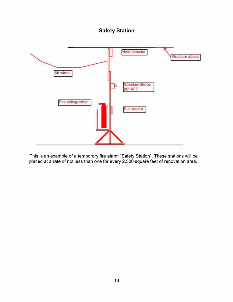
13
Safety Station
This is an example of a temporary fire alarm “Safety Station”. These stations will be placed at a rate of not less than one for every 2,500 square feet of renovation area.

NU DDC Standards

NU DDC Standards Page 2
Table of Contents Point Naming Conventions .................................................................................................. 3
General Abbreviations ..................................................................................................... 4 Building Abbreviations ..................................................................................................... 7
Standard Units, Significant Digits, and Change of Value ........................................................14 Alarm Standards ...............................................................................................................15
Alarm Levels..................................................................................................................15 Alarm Class ...................................................................................................................16
Trending Standards ...........................................................................................................17 Graphic Standards .............................................................................................................19
Universal Graphic Standards ...........................................................................................21 NU Home Screen Graphic ...............................................................................................23 Individual Building Home Screen Graphic .........................................................................24 Floor Plan Graphic .........................................................................................................25 Plant Graphics ...............................................................................................................27 Converter Graphics ........................................................................................................27 AHU Graphics ................................................................................................................28 VAV Graphics ................................................................................................................30

NU DDC Standards Page 3
Point Naming Conventions Point names shall be the combination of several identifying elements that are represented by a list of standard abbreviations. Within a point name, the following attributes shall be identified:
Chicago campus,Evanton campus, or off-campus building (denoted by “C”, “E”, “O”) ,
“F” for Fraternity, “S” for Sorority, “H” for Housing
Building (four letter abbreviation) Equipment tag (if applicable) Point identifier (setpoint, command, alarm, etc)
Attributes shall be separated by “_” and will go from the building name (four letter abbreviation) down to point type (ending in _STP, _CMD, etc where applicable). Equipment tags shall not contain “-“or “/”, and shall be double-digits (i.e. AHU-1 is AHU01 in point name). The naming convention shall be slightly modified depending on if the point is for a piece of equipment, virtual point, meter, etc Examples: CAMPUS_BUILDING_EQUIPMENTTAG_POINTIDENTIFIER_POINTTYPE E_COOK_AHU01_DA_TMP_STPT E_COOK_AHU01_VAV020100:XXX VAV Box point names shall include AHU tag serving the VAV box (or EF tag for exhaust VAV boxes) FOR VAV’S THE FIRST TWO DIGITS AFTER “VAV” WILL REPRESENT THE FLR NUMBER, FOLLOWED BY A FOUR DIGIT ROOM NUMBER. WHERE MORE THAN ONE VAV BOX SERVE A SINGLE ROOM THE VAV TAG SHALL END IN “A”, “B”, “C”, ETC FOR EACH BOX. WHERE A VAV BOX SERVES MULTIPLE ROOMS, THE ROOM NUMBER SHALL BE THE LOCATION OF THE THERMOSTAT. Will all equipment tags other than VAVs be two digit number (i.e. AHU01, CHLR02, etc)?

NU DDC Standards Page 4
General Abbreviations The below abbreviations shall be used for all naming, including:
Point names Graphics Wiring diagrams Equipment labeling Device labeling Wire labeling Design documents
DESCRIPTION ABBREVIATION
AIRFLOW MEASURING STATION AFMS
AIR-HANDLING UNIT AHU
ALARM (Virtual) ALM
BOILER BLR
BREAK TANK BRK_TANK
BROWN WATER BRNW
CABINET UNIT HEATER (HOT WATER) CUH
CHILLED WATER CHW
CHILLED WATER RETURN CHWR
CHILLED WATER SUPPLY CHWS
CHILLER CHLR
CHW COOLING COIL CC
COLD DECK CD
COMMAND (Analog Output) CMD
COMPRESSOR COMP
COMPUTER ROOM AIR CONDITIONER CRAC
CONDENSATE PUMP CS_PMP
CONDENSER WATER CW
CONDENSER WATER PUMP CW_PMP
CONDENSER WATER RETURN CWR
CONDENSER WATER SUPPLY CWS
CONDENSING UNIT CU
CONTROL VALVE VLV
COOLING CLG
COOLING TOWER CT
CROSS CONNECT DAMPER XC_DMPR
CROSS CONNECT VALVE XC_VLV
DEHUMIDIFICATION UNIT DHU
DE-IONIZED WATER DI
DEW POINT DEWP
DIFFERENTIAL (e.g., PRESSURE) DIFF

NU DDC Standards Page 5
DISABLE (Binary Output) DIS
DISCHARGE AIR (out of AHU to terminal device)
DA
DISCHARGE STATIC PRESSURE DA_PRS
DOMESTIC COLD WATER DCW
DOMESTIC HOT WATER HEATER DHW_HX or DHW_HTR
DOMESTIC HOT WATER PUMP DHW_PMP
DOMESTIC HOT WATER RETURN DHWR
DOMESTIC HOT WATER SUPPLY DHWS
DOMESTIC WATER BOOSTER PUMP DCW_PMP
DUCT STATIC PRESSURE DUCT_PRS
DX COOLING COIL DX
ECONOMIZER MODE ECON
ELECTRIC DUCT HEATER EL_DH
ENABLE (Binary Output) ENA
ENERGY-RECOVERY UNIT ERU
ENTHALPY ENTH
EXHAUST AIR EA
EXHAUST AIR DAMPER EA_DMP
EXHAUST FAN (GENERAL) EF
FAN COIL UNIT FCU
FAN POWERED BOX FPB
FILTER FLTR
FINAL FILTER FNL_FLTR
FLOW (AIR) CFM
FLOW (HYDRONIC) GPM
FREQUENCY FREQ
FUME HOOD FH
FUME HOOD CONTROLLER FHC
GEOTHERMAL GEO
GRAY WATER GRYW
HAND-OFF-AUTO HOA
HEAT EXCHANGER HX
HEAT PUMP HT_PMP
HEATING HTG
HEATING COIL HC
HEAT-RECOVERY CHILLER HRC
HEAT-RECOVERY EXHAUST FAN HR_EF
HEPA FILTER HEPA_FLTR
HIGH STATIC SWITCH HI_STAT_ALM
HOT DECK HD
HOT WATER HW
HOT WATER PUMP HW_PMP
HOT WATER RETURN HWR
HOT WATER SUPPLY HWS
HUMIDIFIER HUM
ISOLATION EXHAUST FAN ISO_EF

NU DDC Standards Page 6
ISOLATION ISO
KITCHEN EXHAUST FAN KIT_EF
LAB EXHAUST FAN LAB_EF
LEVEL LVL
LOW LIMIT / FREEZESTAT FRZ
LOW STATIC SWITCH LOW_STAT_ALM
MAKE-UP AIR UNIT MAU
METER MTR
MINIMUM OA DAMPER MIN_OA_DMP
MIXED AIR MA
MIXED AIR PRESSURE MA_PRS
OCCUPIED OCC
OUTSIDE AIR OA
OUTSIDE AIR DAMPER OA_DMP
OVERRIDE OVRD
PACKAGED TERMINAL AIR CONDITIONER PTAC
PERIMETER HOT WATER PERIM_HW
POSITION POS
PRE-FILTER PRE_FLTR
PREHEAT COIL PHC
PRESSURE PRS
PRESSURE REDUCING VALVE PRV
PRIMARY CHILLED WATER PUMP CHW_PMP
PROCESS CHILLED WATER PCHW
PUMP PMP
REHEAT COIL RHC
REHEAT RETURN WATER RHTWR
REHEAT SUPPLY WATER RHTWS
RELATIVE HUMIDITY RH
RELIEF AIR DAMPER RLF_DMP
RELIEF FAN RLF
RETURN AIR RA
RETURN AIR DAMPER RA_DMP
RETURN AIR PRESSURE RA_PRS
RETURN FAN RF
REVERSE OSMOSIS WATER RO
ROOF-TOP UNIT RTU
SECONDARY CHILLED WATER SCHW
SECONDARY CHILLED WATER PUMP SCHW_PMP
SECONDARY HOT WATER SHW
SECONDARY HOT WATER PUMP SHW_PMP
SETPOINT (Virtual point) STPT – if more than one setpoint due to reset schedule abbreviate with _low, _mid, _high, i.e. DA_TMP_STPT_LOW, DA_TMP_STPT_HIGH
SMOKE DETECTOR SMK
SNOW MELT SNOW_MELT

NU DDC Standards Page 7
STAGE STG
STATUS (Binary Input) STS
STEAM STM
SUPPLY AIR (out of terminal device to space) SA
SUPPLY FAN SF
SYSTEM STATIC PRESSURE SYS_PRS
TANK TNK (NUMBER IF APPLICABLE)
TEMPERATURE (DRY BULB) TMP
THERMAL STORAGE TS
TOILET EXHAUST FAN TLT_EF
TOTAL DISSOLVED SOLIDS TDS
TOTAL HARDNESS TH
ULTRA VIOLET FILTER UVLT_FLTR
UNIT HEATER (HOT WATER) UH
UNIT VENTILATOR UV
UNOCCUPIED UNOCC
VARIABLE AIR VOLUME BOX VAV
VARIABLE FREQUENCY DRIVE VFD
VIBRATION SENSOR VIB
WATER SOURCE HEAT PUMP WSHP
WET BULB WB
WIND SPEED WIND_SPD
ZONE DAMPER ZN_DMPR (NOTE: FOR MULTI-ZONE ZN1-DMPR, ZN2_DMPR, ETC)
ZONE PRESSURE ZN_PRS
ZONE TEMPERATURE ZN_TMP
Building Abbreviations
Building # Building Description Address Four Character Abbreviation
8830 Majorie Ward Marshall Dance Center
10 Arts Circle Drive DNCE
8785 Josephine Louis Theater 20 Arts Circle Drive JLTH
8732 Ethel M. Barber Theater 30 Arts Circle Drive BARB
8831 Mary & Leigh Block Museum of Art
40 Arts Circle Drive BLOK
3105 Pick-Staiger Concert Hall 50 Arts Circle Drive PICK
8728 Regenstein Hall of Music 60 Arts Circle Drive REGS
1806 Boat House 1823 Campus Drive BOAT
8737 Kresge Underground 1840 Campus Drive UNDG
8784 Evanston Garage 1847 Campus Drive EVSG
8716 Locy Hall 1850 Campus Drive LOCY
8714 Crowe Hall 1860 Campus Drive CROW
8837 McCormick Tribune Center 1870 Campus Drive TRIB

NU DDC Standards Page 8
Building # Building Description Address Four Character Abbreviation
8785 John J. Louis Hall 1877 Campus Drive LUIS
8714 Kresge Centennial Hall 1880 Campus Drive KRSG
8731 Annie May Swift Hall 1920 Campus Drive AMSW
8732 Theatre and Interpretation Center 1949 Campus Drive THTR
8739 University Library 1970 Campus Drive ULIB
8723 Norris University Center 1999 Campus Drive NORR
8782 Central Utility Plant 2026 Campus Drive ECUP
8789 Walter Annenberg Hall 2120 Campus Drive ANNB
5784 James L. Allen Center 2169 Campus Drive ALLN
8835 Center for Nanofabrication and Molecular Self-Assembly, Ryan Hall
2190 Campus Drive RYNH
8836 Arthur & Gladys Pancoe – Evanston Northwestern Healthcare Life Sciences Pavilion
2200 Campus Drive PANC
8786 William A. & Gayle Cook Hall 2220 Campus Drive COOK
8707 Frances Searle Building 2240 Campus Drive FSRL
1816 Henry Crown Sports Pavilion, Dellora A. & Lester J. Norris Aquatics Center, Combe Tennis Center
2311 Campus Drive SPAC
8607 Ayers College of Commerce & Industry
2324 Campus Drive AYER
8655 Slivka Hall 2332 Campus Drive SLVK
8650 Kemper Hall 2420 Campus Drive KMPR
2244 Chi Phi 550 Lincoln 2244 (BLDG #)
8597 562 Lincoln 562 Lincoln 8597 (BLDG #)
2255 Pi Kappa Alpha 566 Lincoln 2255 (BLDG #)
2261 Theta Chi 572 Lincoln 2261 (BLDG #)
2265 Zeta Beta Tau 576 Lincoln 2265 (BLDG #)
2254 584 Lincoln 584 Lincoln 2254 (BLDG #)
8711 Fisk Hall 1845 Sheridan FISK
8578 East Fairchild 1855 Sheridan EFCH
8579 West Fairchild 1861 Sheridan WFCH
8712 Harris Hall 1881 Sheridan HARR
8738 University Hall 1897 Sheridan UHAL
8709 Charles Deering Library 1937 Sheridan DEER
8719 Arthur Andersen/Donald Jacobs Center: Leverone Hall
2001 Sheridan JACB
8708 Cresap Hall Laboratory 2021 Sheridan CRES
8734 Swift Hall 2029 Sheridan SWFT
8730 Shanley Pavilion 2031 Sheridan SHLY
8717 Lunt Hall 2033 Sheridan LUNT
8715 Garrett – Evangelical Theological Seminary
2121 Sheridan GART

NU DDC Standards Page 9
Building # Building Description Address Four Character Abbreviation
8847 Ford Motor Company Engineering Design Center
2133 Sheridan FORD
8735 Technological Institute – A Wing 2145 Sheridan TIAW
8735 Technological Institute – B Wing 2145 Sheridan TIBW
8735 Technological Institute – C Wing 2145 Sheridan TICW
8735 Technological Institute – D Wing 2145 Sheridan TIDW
8735 Technological Institute – E Wing 2145 Sheridan TIEW
8735 Technological Institute – F Wing 2145 Sheridan TIFW
8735 Technological Institute – G Wing 2145 Sheridan TIGW
8735 Technological Institute – H Wing 2145 Sheridan TIHW
8735 Technological Institute – K Wing 2145 Sheridan TIKW
8735 Technological Institute – L Wing 2145 Sheridan TILW
8735 Technological Institute – M Wing 2145 Sheridan TIMW
8735 Technological Institute – N Wing 2145 Sheridan TINW
8735 Technological Institute – BC Wing 2145 Sheridan TIBC
8735 Technological Institute – AB Wing 2145 Sheridan TIAB
8735 Technological Institute – FG Wing 2145 Sheridan TIFG
8585 Sargent Hall 2245 Sheridan SARG
2253 Phi Kappa Psi 2247 Sheridan 2253 (BLDG #)
2258 Sigma Chi 2249 Sheridan 2258 (BLDG #)
2249 Kappa Sigma 2251 Sheridan 2249 (BLDG #)
8573 Foster House 2253 Sheridan 8573 (BLDG #)
8593 2303 Sheridan 2303 Sheridan 8593 (BLDG #)
8569 Bobb Hall 2305 Sheridan BOBB
2247 Delta Upsilon 2307 Sheridan 2247 (BLDG #)
8580 Lindgren House 2309 Sheridan LNGR
2245 Chi Psi 2313 Sheridan 2245 (BLDG #)
8581 McCulloch Hall 2315 Sheridan MCLH
2246 Delta Tau Delta 2317 Sheridan 2246 (BLDG #)
8575 Goodrich 2321 Sheridan GOOD
2241 2325 Sheridan 2325 Sheridan 2241 (BLDG #)
2252 Phi Gamma Delta 2331 Sheridan 2252 (BLDG #)
2259 Sigma Nu 2335 Sheridan 2259 (BLDG #)
2250 Lamda Chi Alpha 2339 Sheridan 2250 (BLDG #)
2239 Sigma Phi Epsilon 2341 Sheridan 2239 (BLDG #)
8608 Phi Delta Theta 2347 Sheridan 8608 (BLDG #)
2243 Beta Theta Pi 2349 Sheridan 2243 (BLDG #)
1812 Patten Gymnasium 2407 Sheridan PATT
8724 Dearborn Observatory 2131 Tech Drive DBRN
8845 Center for Catalysis & Surface Science
2137 Tech Drive CATL
8713 O.T. Hogan Biological Sciences Building
2205 Tech Drive HOGN
8720 Seeley G. Mudd Library 2233 Tech Drive MUDD
1808 Anderson Hall 2701 Ashland ANDS

NU DDC Standards Page 10
Building # Building Description Address Four Character Abbreviation
1811 McGaw Memorial Hall 2705 Ashland MGAW
1817 Tennis Bubble 2707 Ashland TRIE
1809 Byron S. Coon Sports Center/Nicolet Football
2707 Ashland COON
8743 639 Central 639 Central 8743 (BLDG #)
8744 1808 Chicago 1808 Chicago 8744 (BLDG #)
8745 1809 Chicago 1809 Chicago 8745 (BLDG #)
8746 1810/1812 Chicago 1810/1812 Chicago 8746 (BLDG #)
8747 1815 Chicago 1815 Chicago 8747 (BLDG #)
8567 Allison Hall 1820 Chicago ALLI
8588 1838 Chicago 1838 Chicago 8588 (BLDG #)
8427 Traffic Institute 405 Church 8427 (BLDG #)
R123 1007 Church 1007 Church R123 (BLDG #)
8748 515 Clark 515 Clark 8748 (BLDG #)
8832 555 Clark 555 Clark 8832 (BLDG #)
8704 619 Clark 619 Clark 8704 (BLDG #)
8803 624 Clark 624 Clark 8803 (BLDG #)
8727 Rebecca Crown Center 633 Clark CRWN
8804 618 Colfax 618 Colfax 8804 (BLDG #)
2283 Delta Chi 619 Colfax 2283 (BLDG #)
8805 624 Colfax 624 Colfax 8805 (BLDG #)
8749 625 Colfax 625 Colfax 8749 (BLDG #)
8802 628 Colfax 628 Colfax 8802 (BLDG #)
8750 629 Colfax 629 Colfax 8750 (BLDG #)
8806 617 Dartmouth 617 Dartmouth 8806 (BLDG #)
8751 627 Dartmouth 627 Dartmouth 8751 (BLDG #)
8752 630 Dartmouth 630 Dartmouth 8752 (BLDG #)
8721 Music Administration Building 711 Elgin Road MADM
8729A Cahn Auditorium 600 Emerson CAHN
2273 Delta Gamma 618 Emerson 2273 (BLDG #)
8753 619 Emerson 619 Emerson 8753 (BLDG #)
8568 626 Emerson 626 Emerson 8568 (BLDG #)
8577 Hobart House 630 Emerson HBRT
8733 Health Service 633 Emerson HLTH
2279 Pi Beta Phi 636 Emerson 2279 (BLDG #)
2275 Gamma Phi Beta 640 Emerson 2275 (BLDG #)
8583 North Mid-Quads 650 Emerson NMQD
8595 710 Emerson 710 Emerson 8595 (BLDG #)
8594 720 Emerson 720 Emerson 8594 (BLDG #)
8825 Chambers Hall 600 Foster CHAM
1807 Blomquist Recreation Center 617 Foster BLOM
8872 605-615 Garrett 605-615 Garrett 8872 (BLDG #)
8873 621-623 Garrett 621-623 Garrett 8873 (BLDG #)
8788 618 Garrett 618 Garrett 8788 (BLDG #)

NU DDC Standards Page 11
Building # Building Description Address Four Character Abbreviation
8826 Charles Dawes House 225 Greenwood CDAW
8560 600 Haven 600 Haven 8560 (BLDG #)
8754 617 Haven 617 Haven 8754 (BLDG #)
8755 625 Haven 625 Haven 8755 (BLDG #)
8838 1801 Hinman 1801 Hinman 8838 (BLDG #)
8756 1810 Hinman 1810 Hinman 8756 (BLDG #)
8757 1812 Hinman 1812 Hinman 8757 (BLDG #)
8839 1813 Hinman 1813 Hinman 8839 (BLDG #)
8758 1818 Hinman 1818 Hinman 8758 (BLDG #)
8840 1819 Hinman 1819 Hinman 8840 (BLDG #)
8589 1835 Hinman 1835 Hinman 8589 (BLDG #)
8814 1620 Judson 1620 Judson 8814 (BLDG #)
8760 617 Library 617 Library 8760 (BLDG #)
8821 Family Institute 618 Library FMLY
8808 619 Library 619 Library 8808 (BLDG #)
8761 620 Library 620 Library 8761 (BLDG #)
8762 626 Library 626 Library 8762 (BLDG #)
8590 600 Lincoln 600 Lincoln 8590 (BLDG #)
8599 610 Lincoln 610 Lincoln 8599 (BLDG #)
2256 Career Services 620 Lincoln 2256 (BLDG #)
8566 630 Lincoln 630 Lincoln 8566 (BLDG #)
8920 1801 Maple 1801 Maple 1801
8502 1890 Maple 1890 Maple 8502 (BLDG #)
8598 Engelhart Hall 1915 Maple ENGH
8809 616 Noyes 616 Noyes 8809 (BLDG #)
8763 617 Noyes 617 Noyes 8763 (BLDG #)
8810 624 Noyes 624 Noyes 8810 (BLDG #)
8764 625 Noyes 625 Noyes 8764 (BLDG #)
8765 629 Noyes 629 Noyes 8765 (BLDG #)
R124 1603 Orrington 1603 Orrington R124 (BLDG #)
8601 McManus Living-Learning Center 1725 Orrington MCMN
8610 1856 Orrington 1856 Orrington 8610 (BLDG #)
2270 Chi Omega 1870 Orrington 2270 (BLDG #)
2278 Kappa Kappa Gamma 1871 Orrington 2278 (BLDG #)
8819 1900 Orrington 1900 Orrington 8819 (BLDG #)
8574 Foster-Walker Complex 1927 Orrington FSWK
8815 1941 Orrington 1941 Orrington 8815 (BLDG #)
8823 1948 Ridge 1948 Ridge 8823 (BLDG #)
8844 2020 Ridge 2020 Ridge 2020
8817 1616 Sheridan 1616 Sheridan 8817 (BLDG #)
8767 John Evans Alumni Center 1800 Sheridan 8767 (BLDG #)
8592 1820 Sheridan 1820 Sheridan 8592 (BLDG #)
8706 Alice S. Millar Chapel and Religions Center
1870 Sheridan MLLR

NU DDC Standards Page 12
Building # Building Description Address Four Character Abbreviation
8768 1902 Sheridan 1902 Sheridan 8768 (BLDG #)
8822 1908 Sheridan 1908 Sheridan 8822 (BLDG #)
8769 1914 Sheridan 1914 Sheridan 8769 (BLDG #)
8770 1918 Sheridan 1918 Sheridan 8770 (BLDG #)
8771 1922 Sheridan 1922 Sheridan 8771 (BLDG #)
8772 1936 Sheridan 1936 Sheridan 8772 (BLDG #)
8773 1940 Sheridan 1940 Sheridan 8773 (BLDG #)
8774 2000 Sheridan 2000 Sheridan 8774 (BLDG #)
8775 2006 Sheridan 2006 Sheridan 8775 (BLDG #)
8776 2010 Sheridan 2010 Sheridan 8776 (BLDG #)
8777 2016 Sheridan 2016 Sheridan 8777 (BLDG #)
8778 2040 Sheridan 2040 Sheridan 8778 (BLDG #)
8779 2046 Sheridan 2046 Sheridan 8779 (BLDG #)
8865 Seabury-Western Theological Seminary
2122 Sheridan SEAB
8572 Elder Hall 2400 Sheridan ELDR
8766 2870 Sheridan Place 2870 Sheridan 8766 (BLDG #)
8722 Music Practice Building 1823 Sherman MUPR
8587 Willard Hall 1865 Sherman WILL
8854 1800 Sherman 1800 Sherman 1800
8729 Scott Hall 601 University Place
SCOT
2276 Kappa Alpha Theta 619 University Place
2276 (BLDG #)
2272 Delta Delta Delta 625 University Place
2272 (BLDG #)
8586 Shepard Residential College 626 University Place
SHEP
2266 Alpha Chi Omega 637 University Place
2266 (BLDG #)
8584 Rogers House 647 University Place
ROGR
8582 South Mid-Quads 655 University Place
SMQD
8718 Lutkin Hall 700 University Place
LTKN
2269 Alpha Phi 701 University Place
2269 (BLDG #)
2277 Kappa Delta 711 University Place
2277 (BLDG #)
2274 Delta Zeta 717 University Place
2274 (BLDG #)
8725 Human Resources 720 University Place
HRCS
2248 Evans Scholars 721 University EVAN

NU DDC Standards Page 13
Building # Building Description Address Four Character Abbreviation
Place
8570 Chapin Hall 726 University Place
CHAP
8780 906 University Place 906 University Place
8780 (BLDG #)
8780 910 University Place 910 University Place
8780 (BLDG #)
8780 920 University Place 920 University Place
8780 (BLDG #)
Visitors Center TBD VCTR
Kellogg Building TBD KELG
Bienen School of Music TBD BIEN
Chicago Campus
P102 Chestnut Parking Garage, E-Lot 275 E Chestnut ELOT
P100 Huron Parking Lot, C-Lot 222 E Huron CLOT
P101 Erie Parking Lot, D-Lot 321 E Erie DLOT
8816 Rubloff 375 E Chicago RUBL
8798 Gary Law Library 357 E Chicago GARY
8796 Levy Mayer 357 E Chicago LVMY
8797 McCormick Hall 350 E Superior MCMK
8795 Wieboldt 340 E Superior WBLT
8794 Searle 320 E Superior SRLE
8793 Morton 310 E Superior MORT
8792 Ward 303 E Chicago WARD
8791 Tarry 300 E Superior TARY
8602 Abbott 710 N Lake Shore ABBT
0511 Heating Plant 410 E Huron CCUP
8846 Lurie 303 E Superior LURE
8799 Olson 240 E Huron OLSN

NU DDC Standards Page 14
Standard Units, Significant Digits, and Change of Value The below units, significant digits, and change of value standards shall be used for displaying values in graphics. For example, a static pressure reading displayed on the graphic shall change whenever the sensor reading changes by a value of 0.1, but it shall display two decimal significant digits (i.e. 0.01 significant digits). If a sensor is reading 1.642” w.c., the display shall show 1.64” w.c., and the value on the screen shall not change until the reading changes by 0.1”w.c. (i.e. when the sensor reading changes to a value that can be rounded to 1.54” w.c. or 1.74” w.c.).
Description Units Significant Digits Change of Value
Air Flow CFM 1 1% of Max
Air Static Pressure or Differential Pressure
in/w.c. 0.01 0.01
Air Velocity FPM 1 1% of Max
Building Pressure in/w.c. 0.001 0.005
CO2 Level PPM 5 10
Damper Command and Position
% Open 1 1
Damper Command and Position (F/B damper)
% Face 1 1
Differential Pressure (water systems)
Psig 0.1 0.1
Electric Consumption kWh 1 1% of Max
Electric Current Amps 0.1 1% of Max
Electric Demand kW 1 1% of Max
Electric Potential V 1 1% of Max
Energy BTU 1 1% of Max
Filter Status Clean/Dirty - -
Frequency Hz 0.1 1
Gas Consumption Therms 1 1% of Max
Percent Output % Full 0.1 1
Relative Humidity %RH 1 1
Runtime Hours 1 1
Speed (motor) RPM 1 1
Speed (fan or pump) % 1 1
Status (pump, fan, etc) On/Off - -
Temperature – Critical Spaces °F 0.1 0.1
Temperature – Non-Critical Spaces
°F 0.1 0.5
Valve (modulating) Command & Position
% Open 1 1
Valve (2-pos) Command & Position
Open/Closed - -
Water Flow GPM 1 1% of Max
Water Quality pH 0.01 0.1

NU DDC Standards Page 15
Alarm Standards
Alarm Levels
Type Delay (into alarm)
Delay (out of alarm) Alarm Class
Air-Handling Units
Freezestat None (immediate) None (immediate) Emergency
Fan Status does not match command
5 min. None (immediate) Critical
Hi Static Pressure None (immediate) None (immediate) Critical
Smoke Detector None (immediate) None (immediate) Emergency
Discharge temperature (5°F deviation from setpoint)
5 min. 2 min. Non-critical
Duct static pressure (0.5” wc deviation from setpoint)
5 min. 2 min. Non-critical
Converters
Supply HW temp (10°F deviation
from setpoint)
5 min 5 min. Non-critical
Chiller System
Pump Status does not match command
5 min. None (immediate) Non-critical
Diff. water pressure (5 psig deviation from setpoint)
5 min. 5 min. Non-critical
Chiller status does not match command
5 min. None (immediate) Non-critical
Chiller Alarm None (immediate) None (immediate) Critical
Refrigerant alarm None (immediate) None (immediate) Emergency
CHWS Temp (5°F
deviation from setpoint when chiller enabled)
30 min. 15 min. Non-critical
Boiler System
Boiler status does not match command
5 min. None (immediate) Non-critical
Boiler Alarm None (immediate) None (immediate) Critical

NU DDC Standards Page 16
Type Delay (into alarm)
Delay (out of alarm) Alarm Class
Secondary HW loop temp (10°F
deviation from setpoint when boilers enabled)
30 min. 15 min. Non-critical
Low Steam Pressure Alarm (5 psig below setpoint)
1 min. 1 min. Emergency
Labs
Space pressure 1 min. 1 min. Critical
Exhaust fan status does not match command
5 min. None (immediate) Critical
Space Temperature
Space Temperature (4°F deviation from setpoint)
30 min. (tied to occupied mode, not optimal start)
10 min. Alert
Critical Space Temperature (1°F deviation from setpoint)
30 min. (tied to occupied mode, not optimal start)
5 min. Critical
VFDs
VFD in hand mode or bypass
None (immediate) None (immediate) Critical
Alarm message shall include timestamp, type of alarm, full point name, and value of point (including units) causing alarm.
Alarm Class Link users to alarm type acknowledgement
Alarm Class (in order of least to most critical)
Notified User Group Alarm Routing
Alert DDC Technician Logfile on server
Non-critical DDC Technician Console
Critical* DDC Technician, DDC Foreman E-mail, Pager, and Console
Emergency* DDC Technician, DDC Foreman E-mail, Pager, and Console
Nuclear* DDC Technician, DDC Foreman, Facilities Director
E-mail, Pager, and Console
*Critical, Emergency, and Nuclear alarms shall pop-up on any screen the user is logged into COORDINATE ALARM ROUTING W/OWNER TO DETERMINE PERSONNEL ASSIGNMENTS TO DIFFERENT USER GROUPS. ROUTE PER CAMPUS, ENGINEERING GROUP, AND MANAGEMENT.

NU DDC Standards Page 17
Trending Standards All trends shall be instantaneous trends, not averaging
AHU Trends
Description Trend Interval
Discharge Air Temperature
10 min., Boolean points shall be COV
Mixed Air Temperature
Return Air Temperature
Exhaust Air Temperature
Return Air Humidity
Discharge Air Humidity
Damper Commands
Duct Static
Fan Speed
Valve Position Command
Valve Position Feedback (if available)
Coil Entering/Leaving Water Temperature
Occupied/Unoccupied Mode
COV Fan Status
Heating Coil Pump Status
VAV Trends
Description Trend Interval
Zone Temperature
30 min., Boolean points shall be COV
Airflow
Airflow Setpoint
Damper Position
Perimeter Valve Position
Reheat Valve Position
Leaving Air Temperature
Occupied/Unoccupied Mode COV
Steam/Hot Water Converter Trends
Description Trend Interval
Hot Water Entering Temperature
10 min., Boolean points shall be COV
Hot Water Leaving Temperature
Hot Water Temperature Setpoint
Water Differential Pressure
Steam Valve Command
Steam Valve Position (feedback, if available)
Pump Speed
Pump Enable/Unable Command COV
Pump Status

NU DDC Standards Page 18
Chiller Trends
Description Trend Interval
Chiller CHWS Temperature
10 min., Boolean points shall be COV
Chiller CHWR Temperature
CHWS Setpoint
Chiller CWS Temperature
Chiller CWR Temperature
CW Setpoint
System CHWS Temperature
System CHWR Temperature
Secondary CHWS Temperature
Secondary CHWR Temperature
Chiller CHW Flow (GPM)
Chiller CW Flow (GPM)
System CHW Flow (GPM)
System CW Flow (GPM)
Tower Fan Speed
3-way Bypass Valve Position
Indoor Sump Temperature
Chiller %RLA
Tower Fan Status
COV
Chiller Status
System Differential Pressure
CHW Pump Status
CW Pump Status
Boiler Trends
Description Trend Interval
Boiler HWS Temperature
10 min., Boolean points shall be COV
Boiler HWR Temperature
System HWS Temperature
System HWR Temperature
HWS Temperature Setpoint
Boiler % Fire or High/Low Fire (where applicable)
System HWS Flow (GPM)
3-way Mixing Valve Position
HW Pump Speed
System Differential Pressure COV

NU DDC Standards Page 19
Graphic Standards The graphic hierarchy will be as follows:
NU Home Screen (Opening screen with picture of NU Campus and links to Evanston, Chicago, and Off-Campus)
o Evanston Campus (points beginning with “E”, “F”, “S”, and “H”) List of buildings by type (Science, Academic, Athletic, Housing, Fraternity,
Sorority, Utilities)
Individual Building Home Screen (Dashboard for: instantaneous meter data, alarm statuses, outside air temp/humidity/enthalpy)
o Floor Plan Graphic Detailed Floor Plan Graphic
Dynamic space temperature Occupancy Status (where applicable) Link to VAV graphic
o Equipment Graphics (boilers, chillers, converters, AHUs, etc.)
o Detailed Meter Graphic o AHU status table (valve positions, discharge temps,
damper positions, fan speeds, etc.) o VAV status table(s) (valve position, damper position,
airflow, discharge air temp) o “Other” Graphics
Misc. equipment
Utilities o Evanston CUP Home Screen (status only) o System Meters Screen o One-line diagrams (CHW, Steam, Condensate, etc)
o Chicago Campus (points beginning with “C”) List of buildings by type (FSM, Law, Academic, Utilities)
Individual Building Home Screen (Dashboard for: instantaneous meter data, alarm statuses, outside air temp/humidity/enthalpy)
o Floor Plan Graphic Detailed Floor Plan Graphic
Dynamic space temperature
Occupancy Status (where applicable) Link to VAV graphic
o Equipment Graphics (boilers, chillers, converters, AHUs, etc.)
o Detailed Meter Graphic o AHU status table (valve positions, discharge temps,
damper positions, fan speeds, etc.) o VAV status table(s) (valve position, damper position,
airflow, discharge air temp) o “Other” Graphics
Misc. equipment

NU DDC Standards Page 20
Utilities o Chicago CUP Home Screen (status only) o System Meters Screen o One-line diagrams (CHW, Steam, Condensate, etc)
o Off-Campus (points beginning with “O”) List of buildings
Individual Building Home Screen (Dashboard for: instantaneous meter data, alarm statuses, outside air temp/humidity/enthalpy)
o Floor Plan Graphic Detailed Floor Plan Graphic
Dynamic space temperature Occupancy Status (where applicable)
Link to VAV graphic o Equipment Graphics (boilers, chillers, converters, AHUs,
etc.) o Detailed Meter Graphic o AHU status table (valve positions, discharge temps,
damper positions, fan speeds, etc.) o VAV status table(s) (valve position, damper position,
airflow, discharge air temp) o “Other” Graphics
Misc. equipment

NU DDC Standards Page 21
Universal Graphic Standards Formatting
The default font for words in graphics shall be Tahoma. The minimum font size shall be 12 pt.
Graphic background color shall not be white/shall be lighter color to contrast graphics (coordinate with Owner)
Commandable points shall have a background color (rather than transparent); non-commandable points shall be transparent
Any points in override mode shall appear in different color on the graphic (coordinate with Owner)
At campus-level screens, display status of campus-wide emergency fan shut-down, chiller plant load shedding program, power loss (via “pop-up” alarm status)
Piping shall be color-coded o HWS: bright red o HWR: darker red o CHWS: bright blue o CHWR: darker blue o Steam: white o Condensate: orange o CWS: bright green o CWR: darker green
Graphics shall be designed for screen resolution of 1280x800 (most commonly issued laptop in FM). Useable graphic area will be smaller due to the space needed for the graphic header, upper window bar, and left navigation tree. See below for recommended maximum pixels for graphic header, upper window bar, tabs, and left navigation tree:
Future graphics: graphic for tablets shall be designed using HTML, not Java

NU DDC Standards Page 22
Appearance/Layout
Setpoint the operator can change should appear as a button (defined by user access) Main header – top of screen (banner)
o NU logo o OA conditions (temp, %RH, enthalpy) o Building Name/Equipment tag/Plant description/Service/Location (where
applicable) – located center of banner o Standard Drop-down menu to links
Link to NU BAS home screen Link to NU Campus home screens Link to NU Building abbreviations Link to NU Std. Point Names
o Secondary Drop-down menu (personalized to user)
All setpoints shall be located in upper right corner All alarm points shall be shown on graphic next to associated device (freeze, hi-static,
smoke detector)
Units shall be shown next to all values suing the Standard Units outlined earlier in this document
All points being trended (per Trend Standards) shall have small graphical image of a line chart next to point value that is a button linking the user to 24-hr trends for that point.
Descriptions for points will be typed into background, similar to JCI graphic All equipment graphics (including terminal equipment) shall include a link to:
o Sequence of Operation in .pdf format o Equipment O&M manuals in .pdf format o Wiring diagram and parts list in .pdf format
Piping graphics shall be 2D, not isometric NO VENDOR LOGOS
User shall have ability to leave text notes on graphic Graphic shall display correct type of equipment (centrifugal chiller vs screw chiller,
counter-flow vs. cross-flow cooling tower, inline vs. base-mounted pump, etc) Equipment with VFDs shall have VFD button on graphic that links user to VFD table
showing information available from VFD via BACNET. The VFD table shall include the following parameters:
o Speed Input (%) o Output Speed (RPM) o Output Frequency (Hz) o DC Bus Voltage (V) o Output Voltage (V) o Current (A) o Fault Status o Drive Ready Status o Run Enable Status o Drive Run Status o Drive Mode o Runtime (hr)

NU DDC Standards Page 23
NU Home Screen Graphic
Figure 1: Example Home Screen Graphic
The NU home screen graphic will be similar to the existing Siemen’s NU home screen graphic shown above. The NU home screen graphic will include links to Evanston, Chicago, and Off-campus graphics that each have a list of the buildings associated with that campus.
1. The Evanston home screen graphic shall have alphabetical lists of buildings by the
following building types: Science, Academic, Athletic, Housing, Fraternity, Sorority, Utilities
2. The Chicago home screen graphic shall have alphabetical lists of buildings by the following building types: FSM, Law School, Academic, Utilities
3. The Off-campus building home screen shall have a single alphabetical list of all off-campus buildings

NU DDC Standards Page 24
Individual Building Home Screen Graphic
Figure 2: Example Individual Building Home Screen Graphic
Individual building’s home screen graphics will be similar to Norris’s existing home screen graphic. Per the graphic hierarchy, there shall be links to:
Each Floor Plan Graphic (not shown on Norris example above) Equipment Graphics AHU Status Table Graphic (not shown on Norris example above) VAV Status Table Grpahic (not shown on Norris example above) Detailed Meter Graphics “Other” Graphics (where applicable)
The building home screen graphic shall include a dashboard showing current utility meter readings for that building, along with current outside air temperature/humidity conditions. The graphic shall include a picture of the building, and display the address of the building.

NU DDC Standards Page 25
Floor Plan Graphic
Overall floor plan shall be color-coded/hatched by AHU zones (see Figure 3 below).
There shall be a legend with a list of the AHU tags and associated color. If user clicks on the AHU tag (in the legend), it shall route them to that AHU graphic. If
user clicks on AHU region in floor plan it shall take them to detailed floor plan (see Figure 4 on pg. 26) of that AHU service area.
If area served by an AHU is large and must be split up into several detailed floor plan graphics, then all zones served shall remain one color, but there shall be a boundary (showing the detailed floor plan graphic boundary) that highlights when the user places their mouse in the zones that link to a given detailed floor plan graphic.
Link to as-built floor plan of ductwork/piping
Figure 3: Floor Plan Graphic Example
The above floor plan graphic example shows AHU service zones color-coded by AHU (existing Tech Building graphic). Per this standard, the above graphic will also have a legend showing AHU tag and associated color. If the user clicks on the AHU tag in the legend it shall route them to the AHU graphic. If the user clicks on the AHU service zone in the hatching it shall take them to a detailed floor plan graphic displaying VAV service zones, room temp/humidity.

NU DDC Standards Page 26
Figure 4: Detailed Floor Plan Graphic Example
The above detailed floor plan graphic example shows VAV service zones color-coded by VAV box. The detailed floor plan graphic shall display:
Space temperature Relative humidity (where applicable)
Occupancy status Space Pressure sensor probe location (where applicable)
If space temp, relative humidity (where applicable), or space pressure (where applicable), is out of range, the background color of the point value box shall turn red. If the user clicks on the VAV service zone it shall route them to the VAV graphic.

NU DDC Standards Page 27
Plant Graphics
Animation on cooling tower fans, pumps, (based on status, not output)
One graphic showing combination of all chillers (per existing Chicago) Design for large screen (per existing Chicago) Condenser water and chilled water-side shown on separate graphics with link on graphic
to navigate between the two
Converter Graphics
Flow arrows shall be included on piping Isolation valves shall not be shown; control valves only Graphic shall display correct type of converter (i.e. shell & tube) Graphic shall display correct type of pump (in-line, base-mounted)

NU DDC Standards Page 28
AHU Graphics
Setpoints in upper right corner (main virtual points, occupied mode, reset schedules). Clicking on occupied mode or reset schedules shall take user to additional graphic showing AHU occupancy schedule or reset schedule.
Graphic shall include override buttons for related to terminal equipment served by the AHU that allows user to:
o Override all terminal equipment heating valves fully open o Override all VAV dampers fully open o Override all VAV dampers to max scheduled airflow o Override all VAV dampers to min scheduled airflow o Override all VAV dampers closed
Animation on fans (based on status, not output), not on dampers For systems that are interconnected (energy recovery, EFs, DOAS, etc), but do not all fit
on one graphic, include link on graphic to interconnected system’s graphic
Supply and return airflow shall always be shown from right-edge of graphic (include label)
Exhaust and outside airflow shall always be shown from left-edge of graphic (include label)
Transfer button shown for terminal device graphics Transfer button for related plant equipment (local chiller, boiler, pumps, converters, etc) Graphic shall display both command and feedback points Use standard units and point names described in sections above Each facility shall have a link to an AHU status table. The table shall contain (at
minimum) the following columns (given in order from left to right):
o AHU tag (clicking on this shall link to AHU graphic) o Area Served (i.e. Bio Labs, Chem Classrooms, etc) o Supply/Return/Relief Fan Status – all systems o Supply/Return/Relief Fan Speed – variable volume systems only o Mixed Air Temperature o Damper Position (applicable all dampers at AHU) o Valve position (applicable all HW/CHW/Steam valves) o Discharge Air Temp o Duct Static Pressure
If AHU has multiple supply fans (i.e. fan row) then the AHU row shall be taller and the cell for the supply fan status shall be split into several rows so that all fan status and speeds can be displayed clearly.

NU DDC Standards Page 29
VAV AHU graphics shall have a link to a VAV status table. This table shall display all VAV boxes served from the AHU with the following columns (in order from left to right)
o VAV tag (clicking on this shall link to VAV box graphic) o Room(s) served o Zone temperature setpoint o Zone temperature o Discharge air temperature o Reheat valve position o Damper position o Airflow setpoint o Airflow
Final row of VAV status table shall show minimum and maximum discharge air temperature, minimum and maximum reheat valve position, minimum and maximum damper position, and total airflow. If a system is large enough to require multiple VAV status tables, this final row shall be shown at the bottom of each table

NU DDC Standards Page 30
VAV Graphics
Setpoints in upper right corner (main virtual points). Shall include min. heat, min. cool, max heat, max cool CFM, space temperature setpoint (where applicable)
Room name and number shall be included in the VAV object name. Coordinate final room numbers with owner. Where VAV box serves more than one room, the room number shall be the room where the thermostat is located.
Where more than one VAV serves a single room there shall be a typical VAV graphic at the top of the screen with a table below showing values for airflow, damper position, discharge air temp, etc. Table shall include room airflow totals at bottom row of the table. Any exhaust dampers associated with a VAV box shall also be shown on the graphic, included in the tables
Include link to AHU graphic serving VAV box

Northwestern University Scope of BAS Contractor
Page 1 of 5 1/15/2014
The purpose of this document is to describe the Enterprise Level Server at Northwestern University, and the separation of roles between the System Integrator and the Building Automation System Contractor. The Enterprise Server consists of the Honeywell Tridium WebsAX running on three Marathon redundant servers. Two servers are located on the Evanston Campus, and one server is located on the Chicago Campus. Both the JCI and Siemens head end servers currently reside on this Marathon redundant server. The long term plan is these two software packages are used for high level programming only, and will not be used for day to day operations of the JCI or Siemens BAS. All new DDC system controllers, terminal device controllers, VFDs, and any other intelligent control device shall be BTL Certified and shall communicate using BACNET MS/TP. All network controllers shall communicate to lower level controllers using BACNET MS/TP. Network controllers shall communicate to each other, and BAS Servers, using BACNET/IP. The control contractor shall provide a complete DDC system, which interfaces with both the control vendors "head end" server, and the Northwestern University Tridium Enterprise Server. The Owners' normal day to day interface will be with the Tridium Enterprise Server. The configuration of graphics for the Tridium Enterprise Server will be done by the Owner's System Integrator. The BAS contractor is responsible for coordinating with the System Integrator to verify all points are properly transmitted to the Enterprise Server including alarm values and links to trend files. Provide sufficient manpower to work with the System Integrator to do a point to point test of alarms, trending, setpoint overrides, etc. Figure 1 shows a simple schematic of the Enterprise Network.

Northwestern University Scope of BAS Contractor
Page 2 of 5 1/15/2014
Figure 1: Simplified Riser Diagram

Northwestern University Scope of BAS Contractor
Page 3 of 5 1/15/2014
Role of the Building Automation System Contractor (BASC)
1. Provide the field devices and wiring including DDC controllers, relays, sensors, transducers, control devices, control panels, controller programming, controller programming software, controller input/output and power wiring and controller network wiring to provide a complete working system of the mechanical equipment.
2. Submittals: Provide an electronic copy of the specification sheets for the equipment and DDC controls being provided for the specific project. The drawings shall be drawn in Visio or AutoCAD, and shall include separate sections for the following: index page, a riser diagram, flow diagrams, panel detail, wiring schematics, termination of controllers, full points list including any global or virtual points, any valve schedules and damper schedules.
3. Use the Northwestern University DDC Standard document for point naming structure.
4. Provide as-built drawings and O&M Manuals in electronic form (Visio or MS Word or Adobe pdf format).
5. Provide Network Controllers as required for a project. Coordinate quantity and locations of new network controller with Owner and System Integrator. Acceptable network controllers are manufactured by Siemens, Tridium, Johnson Controls, Delta Controls, and Automated Logic Corporation.
6. Network Controllers:
a. Johnson Controls:
i. Provide most current Metasys controller compatible with the existing Johnson Controls campus infrastructure.
ii. Communication to field control devices shall be through BACNET MS/TP, not JCI N2 unless approved by NU for specific applications.
b. Siemens Controls:
i. Provide most current Apogee controller compatible with the existing Siemens campus infrastructure. PXC Modular is preferred to PXC Compact.
ii. Communications to field control devices shall be through BACNET MS/TP, not Siemens FLN unless approved by NU for specific applications.
c. Honeywell Tridium:
i. Northwestern University has standardized on the Honeywell WEB-600-O-US NiagaraAX™ Controller, to follow a consistent standard of design and operation supporting overall system conformance standards. Other branded NiagaraAX™ network controllers are unacceptable.
ii. All network controller hardware products shall be “Made in the USA” or come through the Tridium Richmond, Virginia shipping facility.

Northwestern University Scope of BAS Contractor
Page 4 of 5 1/15/2014
iii. All network controllers shall include a lifetime license for free software upgrades.
iv. The network controllers shall be provided with no connectivity restrictions on which brand stations or tools can interact with the system. The station and tool “NiCS” would be as follows:
Property Value
STATION COMPATIBILITY IN ALL
STATION COMPATIBILITY OUT ALL TOOL COMPATIBILITY IN ALL
TOOL COMPATIBILITY OUT ALL d. Delta Controls:
i. Northwestern University does not have a standard developed for Delta Controls at the time of publication.
e. Automated Logic
i. Provide most current controller compatible with existing ALC campus infrastructure.
ii. Communications to field control devices shall be through BACNET MS/TP.
7. Point to point checkout.
8. Verify all physical alarms.
9. Setup alarms in the network controller in accordance with the Northwestern University DDC Standards document. Coordinate with Owner on alarm distribution. Work with the SI to make sure the Enterprise Server is receiving the alarms.
10. Setup trends in the BASC’s associated server in accordance with the Northwestern University DDC Standards document. Work with the SI to make sure the Enterprise Server is receiving the trends.
11. Accessing controllers via PCAnywhere, Telnet or similar software is not allowed. Remote access shall be through Northwestern’s SSLVPN.
12. Any software required for controller configuration shall be included as a leave-behind tool with enough license capability to support the installation. Provide the appropriate quantity of legal copies of all software tools, configuration tools, management tools, and utilities used during system commissioning and installation. All tools shall be generally available in the market. No closed and/or unavailable tools will be permitted. Contractor shall convey all software tools and their legal licenses at project close out.

Northwestern University Scope of BAS Contractor
Page 5 of 5 1/15/2014
Role of the System Integrator (Separate Contract):
1. The System Integrator (SI), Engineer, Owner and selected Building Automation System Contractor (BASC) meet to review the project so that all programming, design standards and job specific requirements are consistent with the NU DDC Standards.
2. Coordinate with the BASC to ensure point discovery and integration is scheduled at appropriate times during construction.
3. The SI shall be responsible to build/create the graphic layout/background slides in conformance with the Northwestern University DDC Standards document. The graphics shall be resident on the Enterprise Server.
4. Maintain point naming structure. Verify BASC is adhering to the naming convention.
5. Coordinate with the BASC to verify proper alarm input to the Enterprise server, and display on the graphics.
6. Coordinate with the BASC to verify proper link to the trend files on the Enterprise server graphics.
7. Setup event log.
8. Merge project O&M documents, including the control drawings, into a common system O&M manual.
9. Work with the Owners IT Department to establish I/P network addresses with BACnet instance IDs and ensure the appropriate I/P addresses with BACnet instance IDs are used throughout the BAS Enterprise.
10. Maintain the Energy Analytics software on the Marathon redundant server, including all software upgrades.

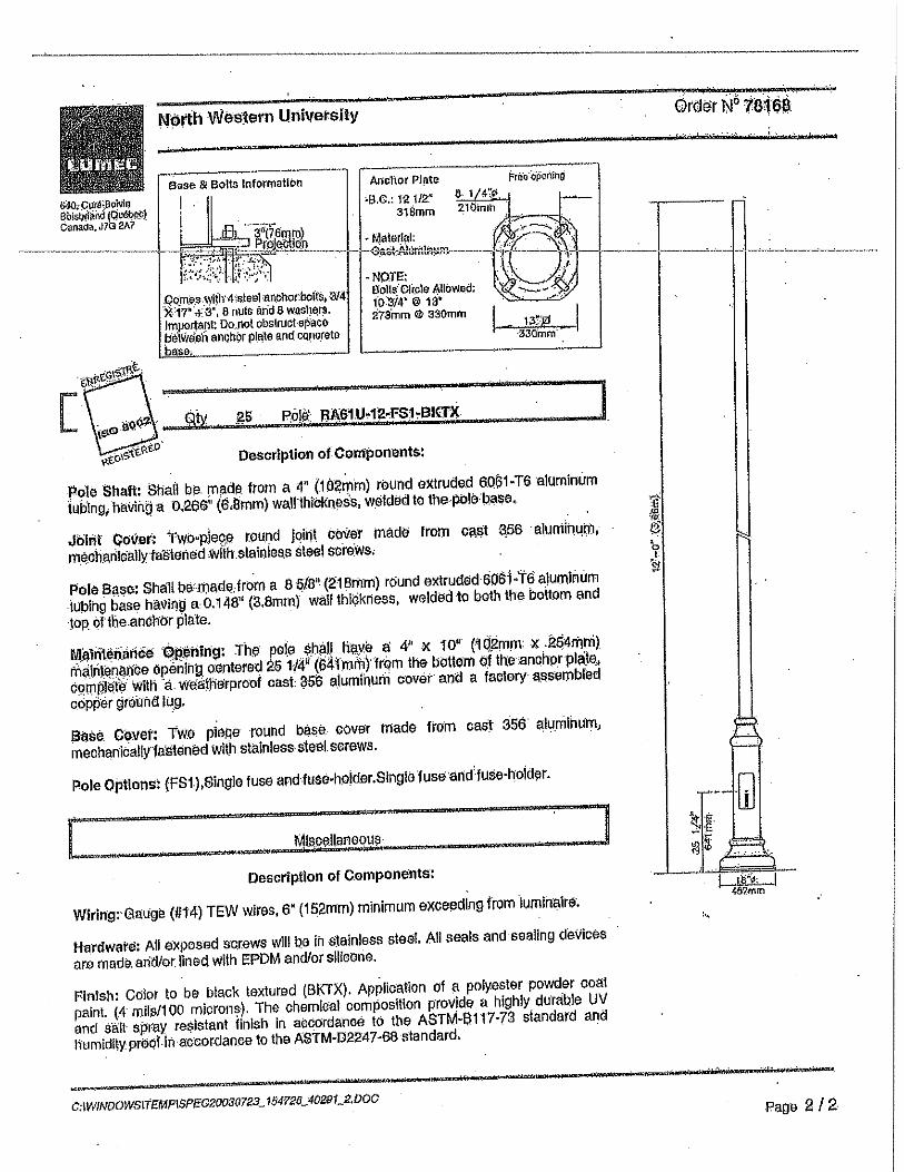
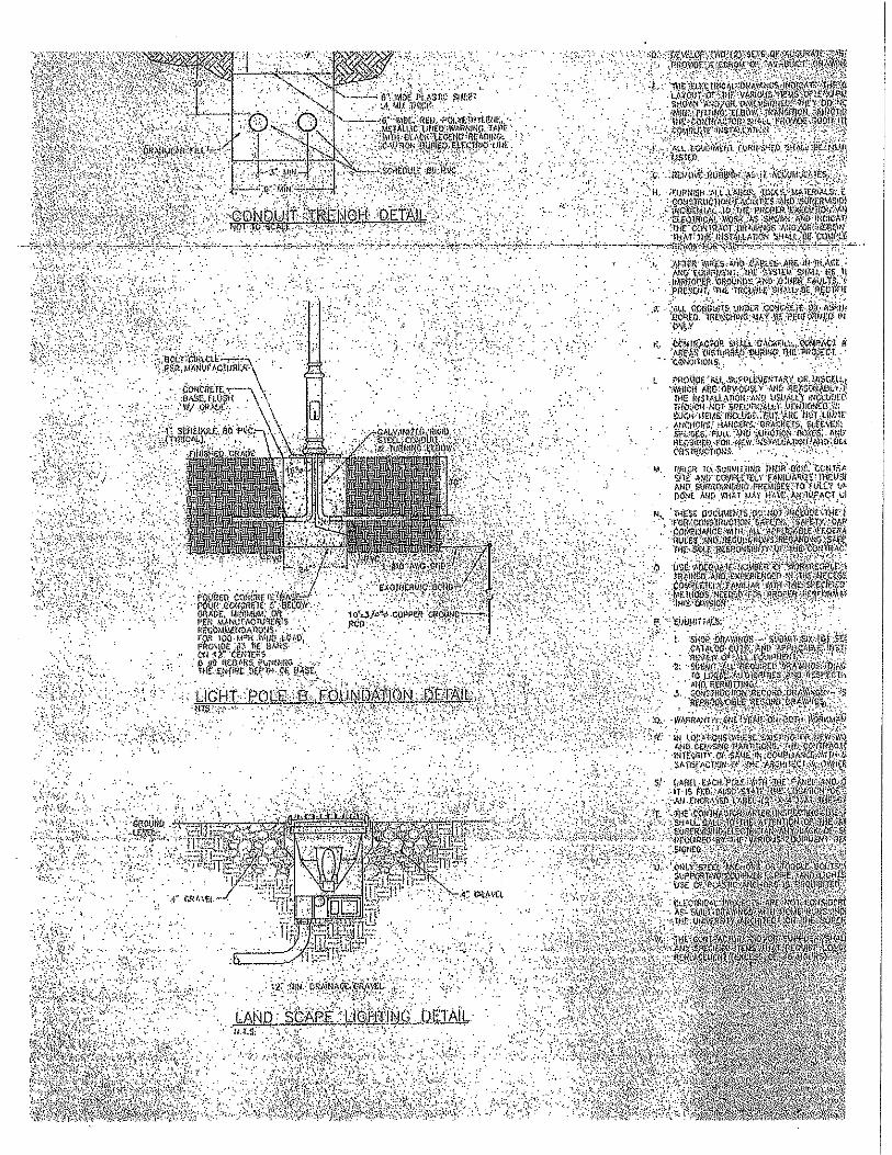


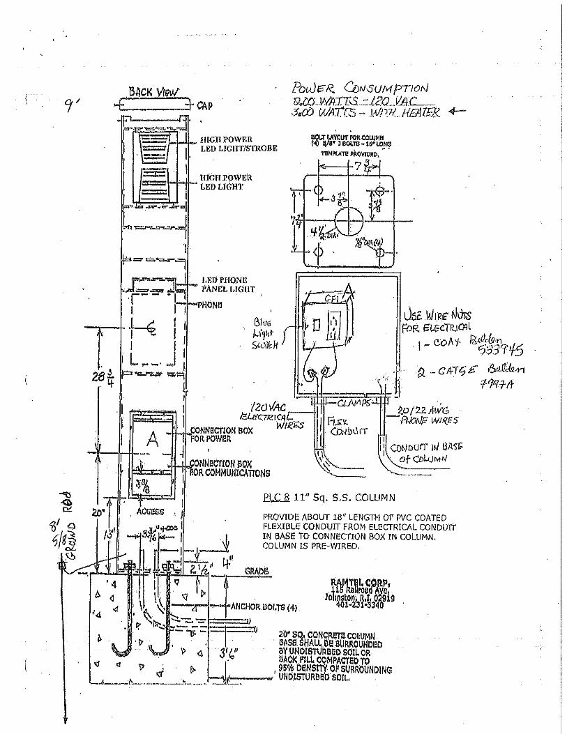


Woodbench Specifications
Gretchen Bench
Available backed or backless. Backed version available with two armrest
styles — loop or ornamental. Offered in 72" or 96" lengths. Freestanding,
surface mounted, or wall mounted styles offered. Available in a variety of
woods or PolySite™ recycled timbers (PolySite not offered in 96" length).
Gretchen Picnic Table
Wheelchair accessible from either end. Available in a variety of woods or
PolySite™ recycled timbers. Freestanding or surface mounted. Umbrella hole
available. ADA compliant style available. Contact Landscape Forms for details.
Gretchen Litter Receptacle and Ash Urn
Large 30-gallon capacity receptacle with liner. Choose from side or top
opening receptacle styles. Sand pan available for side opening receptacle.
Available in a variety of woods or PolySite™ recycled timbers. Coordinating
ash urn available.
Balustrade
Constructed of 2" x 3" wood rails individually fastened to steel bands. Available
backed or backless. Backed bench offered in 72" and 96" lengths, backless
in 72" only. End loop arm available on backed bench. Freestanding, embed-
ded, surface mounted or wall mounted styles offered. Available in a variety
of woods or PolySite™ recycled timbers (PolySite™ not offered in 96" length).
Palisade and Shadowline
Backless benches are constructed of solid wood, fastened together with
internal steel rods. Available in 72" and 96" lengths. Palisade is freestanding,
and offered in a variety of woods. Anchor clips available. Shadowline offered
in a variety of woods. May be surface mounted, embedded, freestanding or
wall mounted.
Finishes
Interior woods are finished with Landscape Forms’
exclusive LF-80 wood finish, a clear, catalyzed acrylic
catalyzed acrylic lacquer.
Exterior woods are unfinished and will weather to a soft
pewter gray, requiring no future maintenance.
Metal is finished with Landscape Forms’ proprietary
Pangard II® polyester powercoat, a hard yet flexible
finish that resists rusting, chipping, peering and fading.
Call for standard color chart. A wide array of optional
colors may be specified for an upcharge.
Consult Landscape Forms price list for complete
specifying information. Visit landscapeforms.com; click
Design Tools, Materials/Colors link for standard offer-
ings, including FSC wood options.
Our Purpose Is To Enrich Outdoor Spaces
We believe in the power of design and its abil ity to
elevate experience and help create a sense of place
in public environments. Our high quality products and
outstanding customer service have earned us a
reputation as one of the world’s premier designers
and manufacturers of outdoor commercial furnishings.
Metal is the world’s most recycled material and is fully recyclable. Powdercoat finish
on metal parts contains no heavy metals, is HAPS-free and has extremely low VOCs.
Consult our website for recycled content for this product.
Landscape Forms is proud to specify FSC and Green-e certified paper. This paper meets
the Forest Stewardship Council’s standards for responsible forest management and is
made using certified renewable energy.
Cover Photo: Shadowline Bench
Specifications are subject to change without notice.
Woodbench collection is manufactured in U.S.A.
Location Photography : Kalamazoo Institute of Arts
Landscape Forms supports the LAF at the Second Century level.
©2011 Landscape Forms, Inc. Printed in U.S.A.
800.521.2546 269.381.3455 fax
431 Lawndale Avenue, Kalamazoo, MI 49048
www.landscapeforms.com
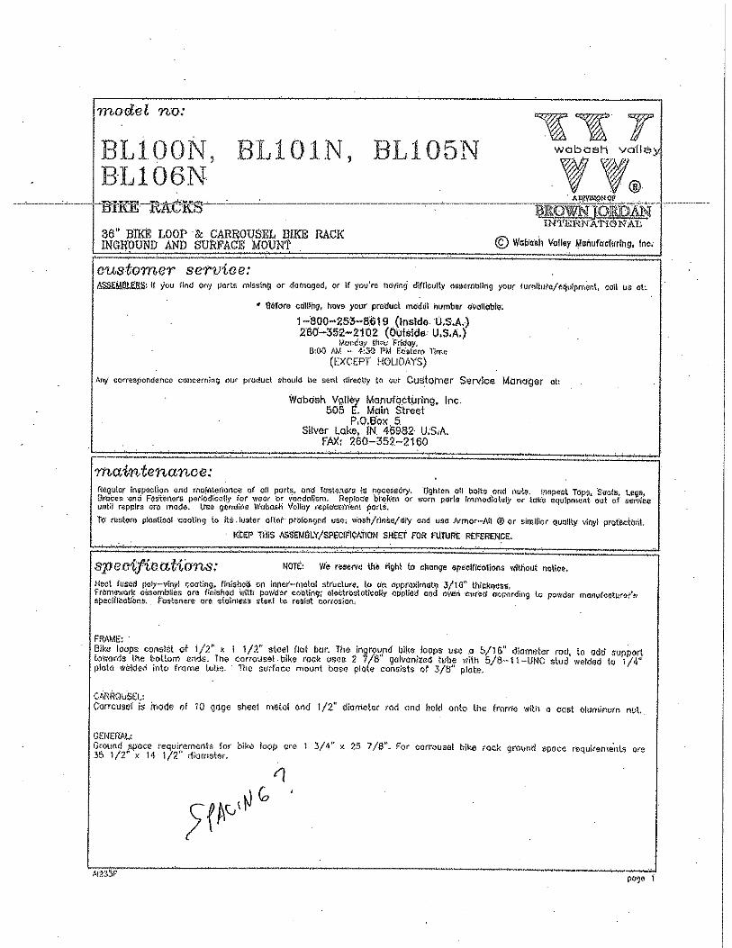


VICTOR STANLEY, INC.-Manufacturers of Quality Site Furnishings since 1962-P.O. Drawer 330, Dunkirk, Maryland 20754 USA
www.victorstanley.com
DYN-342 and DYN-242 Dynasty Series™ MegaCan Recycling Stations and Litter Receptacles
Patents Pending