design manual, part 2 highway design - cdn.ymaws.com · table of contents publication 13m (dm-2)...
TRANSCRIPT

Table of Contents Publication 13M (DM-2) 2015 Edition - Change #1
TOC - 1
DESIGN MANUAL, PART 2 HIGHWAY DESIGN
TABLE OF CONTENTS
CHAPTER SUBJECT PAGE CHAPTER 1 GENERAL DESIGN 1.0 INTRODUCTION ...........................................................................................................................................1 - 1 1.1 STANDARDS FOR ROADWAY CONSTRUCTION ...................................................................................1 - 3 1.2 DESIGN CRITERIA .......................................................................................................................................1 - 3 A. Definitions of Design Criteria ................................................................................................................1 - 4 B. Functional Classifications, Typologies, and Low Cost Safety Measures ...............................................1 - 7 C. Minimum Width Criteria for Bridges ................................................................................................... 1 - 26 D. Shoulder Criteria for New Construction and Reconstruction Projects ................................................. 1 - 30 E. Design Criteria for Resurfacing, Reconstruction and Rehabilitation (3R) Projects ............................. 1 - 31 1.3 PAVEMENT PRESERVATION CRITERIA ................................................................................................ 1 - 37 A. Non-Freeway Criteria ........................................................................................................................... 1 - 37 B. Freeway Criteria ................................................................................................................................... 1 - 37 1.4 THIS SECTION IS INTENTIONALLY LEFT BLANK .............................................................................. 1 - 38 1.5 TYPICAL ROADWAY CROSS SECTIONS ............................................................................................... 1 - 38 Interstate and Other Limited Access Freeways .............................................................................................. 1 - 40 Arterials ......................................................................................................................................................... 1 - 52 Arterials, Collectors and Local Roads ............................................................................................................ 1 - 56 Collectors and Local Roads ........................................................................................................................... 1 - 58 Typical Pavement Widening .......................................................................................................................... 1 - 60 Typical Roadway Cross Section Notes .......................................................................................................... 1 - 62 1.6 ACCELERATION AND DECELERATION (SPEED-CHANGE)AUXILIARY LANES ........................... 1 - 64 1.7 CONTROL OF ACCESS ............................................................................................................................... 1 - 64 1.8 STAGE CONSTRUCTION ........................................................................................................................... 1 - 66 APPENDIX A Reduced Bridge Width Criteria Documentation ....................................................................... 1A - 1 CHAPTER 2 DESIGN ELEMENTS AND DESIGN CONTROLS 2.0 INTRODUCTION ...........................................................................................................................................2 - 1 2.1 HORIZONTAL ALIGNMENT .......................................................................................................................2 - 1 2.2 VERTICAL ALIGNMENT .............................................................................................................................2 - 2 2.3 CONTROLS FOR COMBINATION HORIZONTAL AND VERTICAL ALIGNMENTS ...........................2 - 2 2.4 SIMPLE CURVE COMPUTATIONS .............................................................................................................2 - 3 2.5 SURVEY AND CONSTRUCTION BASELINES ..........................................................................................2 - 4 2.6 MINIMUM RADIUS .......................................................................................................................................2 - 8 A. Definition ...............................................................................................................................................2 - 8 B. Design for Rural Highways, Urban Freeways and High-Speed Urban Streets ........................................2 - 8 C. Design for Low-Speed Urban Streets ......................................................................................................2 - 8 2.7 GRADES..........................................................................................................................................................2 - 9 2.8 CRITICAL LENGTH OF GRADE................................................................................................................ 2 - 10 2.9 DESIGN SPEED ............................................................................................................................................ 2 - 10 A. Projects with New or Modified Speed Posting ...................................................................................... 2 - 11 B. Projects Maintaining Existing Speed Posting ........................................................................................ 2 - 11 C. Existing Roadways with No Posted Regulatory Speed Limit ............................................................... 2 - 11 D. Non-Applicable Design Speeds ............................................................................................................. 2 - 11 2.10 TERRAIN ...................................................................................................................................................... 2 - 11 2.11 CLIMBING LANES ...................................................................................................................................... 2 - 12
Step 1 CT - Sept. 2016

Table of Contents Publication 13M (DM-2) 2015 Edition - Change #1
TOC - 2
2.12 VERTICAL CURVES ................................................................................................................................... 2 - 13 A. General Considerations ......................................................................................................................... 2 - 13 B. Crest Vertical Curves ............................................................................................................................ 2 - 13 C. Sag Vertical Curves ............................................................................................................................... 2 - 13 2.13 SUPERELEVATION..................................................................................................................................... 2 - 13 A. General ..................................................................................................................................................2 - 13 B. Rates of Superelevation ......................................................................................................................... 2 - 15 C. Maximum Superelevation ..................................................................................................................... 2 - 15 D. Superelevation Transition (T) ................................................................................................................ 2 - 15 E. Application of Superelevation ........................................................................................................... 2 - 2325 F. Superelevation of City Streets ........................................................................................................... 2 - 2426 G. Superelevation for Curves on Ramps ................................................................................................ 2 - 2426 2.14 TRAVELED WAY WIDENING ON HORIZONTAL CURVES ............................................................. 2 - 2426 2.15 TRANSITION (SPIRAL) CURVES AND COMPUTATIONS ................................................................ 2 - 2527 2.16 AIRPORT - HIGHWAY CLEARANCES ................................................................................................. 2 - 3133 2.17 SIGHT DISTANCE ................................................................................................................................... 2 - 3133 A. General .............................................................................................................................................. 2 - 3133 B. Criteria for Measuring Sight Distance ............................................................................................... 2 - 3133 C. Passing Sight Distance for Two-Lane Highways .............................................................................. 2 - 3133 D. Stopping Sight Distance .................................................................................................................... 2 - 3337 E. Decision Sight Distance .................................................................................................................... 2 - 3438 F. Intersection Sight Distance ................................................................................................................ 2 - 3438 G. Sight Distance for Multilane Highways ............................................................................................ 2 - 3539 H. Sight Distance on Horizontal Curves ................................................................................................ 2 - 3539 2.18 OTHER ELEMENTS AFFECTING GEOMETRIC DESIGN .................................................................. 2 - 3640 A. Traffic Control Devices ..................................................................................................................... 2 - 3640 B. Intelligent Transportation Systems ....................................................................................................2 - 3640 C. Erosion Control ................................................................................................................................. 2 - 3640 D. Landscape Development ................................................................................................................... 2 - 3741 E. Railroad-Highway Grade Crossings .................................................................................................. 2 - 3741 F. Drainage ............................................................................................................................................ 2 - 3741 G. Lighting ............................................................................................................................................. 2 - 3741 H. Safety Rest Areas, Welcome Centers and Scenic Overlooks ............................................................ 2 - 3842 I. Utilities .............................................................................................................................................. 2 - 3842 J. Bicycle Facilities ............................................................................................................................... 2 - 3842 K. Noise Control and NoiseSound Barriers............................................................................................ 2 - 3842 L. Structures ......................................................................................................................................... 2 - 3943 M. Pedestrian Facilities ........................................................................................................................... 2 - 3943 N. Highway Capacity Analysis .............................................................................................................. 2 - 3943 O. Mass Transit Facilities ....................................................................................................................... 2 - 3943 P. Special Purpose Roads ...................................................................................................................... 2 - 3943 Q. Traffic Barriers .................................................................................................................................. 2 - 4044 R. Curbs and Driveways ........................................................................................................................ 2 - 4044 S. Maintenance of Traffic Through Construction Areas ........................................................................ 2 - 4044 T. Outer Separations and Border Areas ................................................................................................. 2 - 4044 U. Median Crossovers ............................................................................................................................ 2 - 4145 2.19 DESIGN CONTROLS ............................................................................................................................... 2 - 4650 A. Design Vehicles ................................................................................................................................. 2 - 4650 B. Driver Performance and Human Factors ........................................................................................... 2 - 4650 C. Traffic Characteristics ....................................................................................................................... 2 - 4751 D. Safety ................................................................................................................................................. 2 - 4852 E. Environment ...................................................................................................................................... 2 - 4852 F. Economic Analysis ............................................................................................................................ 2 - 4852 2.20 VERTICAL CLEARANCE REQUIREMENTS ....................................................................................... 2 - 4852 A. Strategic Highway Network (STRAHNET) ...................................................................................... 2 - 4852 B. Bridges over Railroads ...................................................................................................................... 2 - 4953 C. Pedestrian Overpasses ....................................................................................................................... 2 - 4953
Step 1 CT - Sept. 2016

Table of Contents Publication 13M (DM-2) 2015 Edition - Change #1
TOC - 3
D. Traffic Signals ................................................................................................................................... 2 - 4953 E. Utility Lines ....................................................................................................................................... 2 - 4953 APPENDIX A Vertical Clearance Design Exception Coordination with Surface Deployment and Distribution Command Transportation Engineering Agency (SDDCTEA) .............................. 2A - 1 CHAPTER 3 INTERSECTIONS 3.0 INTRODUCTION ...........................................................................................................................................3 - 1 3.1 OBJECTIVES AND FACTORS FOR DESIGN CONSIDERATIONS ..........................................................3 - 1 3.2 TYPES OF INTERSECTIONS ........................................................................................................................3 - 1 3.3 GEOMETRIC DESIGN ELEMENTS .............................................................................................................3 - 2 A. Alignment and Profile .............................................................................................................................3 - 2 B. Types of Turning Roadways....................................................................................................................3 - 2 C. Sight Distance ..........................................................................................................................................3 - 3 D. Superelevation .........................................................................................................................................3 - 4 E. Traffic Islands ..........................................................................................................................................3 - 4 F. Median Openings ....................................................................................................................................3 - 4 G. Acceleration and Deceleration (Speed-Change)Auxiliary Lanes ............................................................3 - 5 H. Direct and Indirect Left Turns and U-Turns ............................................................................................3 - 5 I. Auxiliary Lanes .......................................................................................................................................3 - 5 JI. Curb Radii for Turning Movements in Urban Areas ...............................................................................3 - 5 KJ. Free-Flow Turning Roadways at Intersections ........................................................................................3 - 5 LK. Channelization .........................................................................................................................................3 - 6 ML. Additional Design Considerations ...........................................................................................................3 - 6 3.4 HIGHWAY CAPACITY ANALYSIS AND TRAFFIC CONTROL ..............................................................3 - 6 3.5 ROUNDABOUTS ...........................................................................................................................................3 - 7
A. Introduction .............................................................................................................................................3 - 7 B. Planning ...................................................................................................................................................3 - 7 C. Operations ............................................................................................................................................. 3 - 11 D. Safety ..................................................................................................................................................... 3 - 12 E. Design .................................................................................................................................................... 3 - 12 F. Other Considerations ............................................................................................................................. 3 - 15
APPENDIX A Roundabout Key Considerations Checklist ............................................................................... 3A - 1 CHAPTER 4 GRADE SEPARATIONS AND INTERCHANGES 4.0 INTRODUCTION ...........................................................................................................................................4 - 1 4.1 TYPES OF INTERCHANGES ........................................................................................................................4 - 1 4.2 WARRANTS FOR GRADE SEPARATIONS AND INTERCHANGES .......................................................4 - 1 4.3 ADAPTABILITY OF HIGHWAY GRADE SEPARATIONS AND INTERCHANGES ..............................4 - 2 4.4 GRADE SEPARATION STRUCTURES ........................................................................................................4 - 2 A. Types of Separation Structures ................................................................................................................4 - 2 B. Overpass Versus Underpass Roadways ...................................................................................................4 - 2 C. Underpass Roadways...............................................................................................................................4 - 2 D. Overpass Roadways.................................................................................................................................4 - 3 E. Longitudinal Distance to Attain Grade Separation ..................................................................................4 - 3 F. Grade Separations Without Ramps ..........................................................................................................4 - 3 4.5 INTERCHANGES ...........................................................................................................................................4 - 4 A. Determination of Interchange Configuration ...........................................................................................4 - 4 B. Approaches to the Structure ....................................................................................................................4 - 4 C. Interchange Spacing ................................................................................................................................4 - 4 D. Uniformity of Interchange Patterns .........................................................................................................4 - 5 E. Route Continuity .....................................................................................................................................4 - 5 F. Overlapping Routes .................................................................................................................................4 - 5 G. Signing and Marking ...............................................................................................................................4 - 5
Step 1 CT - Sept. 2016

Table of Contents Publication 13M (DM-2) 2015 Edition - Change #1
TOC - 4
H. Basic Number of Lanes ...........................................................................................................................4 - 5 I. Coordination of Lane Balance and Basic Number of Lanes ....................................................................4 - 5 J. Auxiliary Lanes .......................................................................................................................................4 - 5 K. Lane Reductions ......................................................................................................................................4 - 5 L. Collector-Distributor Roads Within an Interchange ................................................................................4 - 5 M. Two-Exit Versus Single-Exit Interchange Design ...................................................................................4 - 5 N. Wrong-Way EntrancesEntry....................................................................................................................4 - 5 O. Other Interchange Design Features .........................................................................................................4 - 5 4.6 WEAVING SECTIONS ..................................................................................................................................4 - 5 4.7 RAMPS ............................................................................................................................................................4 - 6 A. Types and Examples ................................................................................................................................4 - 6 B. General Ramp Design Considerations .....................................................................................................4 - 6 C. Ramp Traveled-Way Widths ...................................................................................................................4 - 6 D. Ramp Terminal Design ............................................................................................................................4 - 6 E. Ramp Capacity Analysis and Traffic Control .........................................................................................4 - 8 F. Ramp Design Sheet .................................................................................................................................4 - 8 CHAPTER 5 LIGHTING 5.0 INTRODUCTION ...........................................................................................................................................5 - 1 5.1 SITE INSPECTION .........................................................................................................................................5 - 1 5.2 PRELIMINARY DESIGN ...............................................................................................................................5 - 2 A. Conventional Lighting .............................................................................................................................5 - 2 B. High Mast Lighting .................................................................................................................................5 - 4 5.3 PRELIMINARY DESIGN REPORT...............................................................................................................5 - 5 5.4 LUMINAIRES .................................................................................................................................................5 - 5 A. Conventional Lighting .............................................................................................................................5 - 5 B. High Mast Lighting .................................................................................................................................5 - 5 5.5 POLES . ...........................................................................................................................................................5 - 6 A. Conventional Lighting .............................................................................................................................5 - 6 B. High Mast Lighting .................................................................................................................................5 - 9 5.6 UNDERPASS LIGHTING ..............................................................................................................................5 - 9 5.7 TUNNEL LIGHTING .................................................................................................................................... 5 - 10 5.8 SAFETY REST AREAS, WELCOME CENTERS AND PERMANENT TRUCK WEIGH STATIONS ...................................................................................... 5 - 10 5.9 FINAL DESIGN ............................................................................................................................................ 5 - 10 5.10 POWER SUPPLY .......................................................................................................................................... 5 - 11 5.11 MULTIPLE DISTRIBUTION SYSTEM ...................................................................................................... 5 - 11 5.12 SAMPLE DESIGN REPORTS ...................................................................................................................... 5 - 11 CHAPTER 6 PEDESTRIAN FACILITIES AND THE AMERICANS WITH DISABILITIES ACT 6.0 INTRODUCTION ...........................................................................................................................................6 - 1 6.1 DEFINITIONS .................................................................................................................................................6 - 2 6.2 ADA REQUIREMENTS, STANDARDS AND GUIDELINES .....................................................................6 - 4
A. New Construction Projects ......................................................................................................................6 - 5 B. Alteration Projects and Removing Existing Pedestrian Access Barriers .................................................6 - 5 C. Unaltered Existing Facilities ...................................................................................................................6 - 9
6.3 PROJECT TYPE EXAMPLES ...................................................................................................................... 6 - 10 A. Maintenance Type Projects ................................................................................................................... 6 - 10 B. Alteration Type Projects ........................................................................................................................ 6 - 10 C. Reconstruction and New Construction Type Projects ........................................................................... 6 - 12 D. Connections to Existing Facilities ......................................................................................................... 6 - 13
6.4 LIAISON WITH LOCAL GOVERNMENT AND PRIVATE PROPERTY OWNERS ............................... 6 - 13 A. Americans with Disabilities Act: Reimbursement and Maintenance for Curb Ramps
with Local Municipalities .......................................................................................................... 6 - 13 B. Installing Curb Ramps Located Outside of the Public Right-of-Way ................................................... 6 - 15
Step 1 CT - Sept. 2016

Table of Contents Publication 13M (DM-2) 2015 Edition - Change #1
TOC - 5
6.5 PEDESTRIAN ACCESS ROUTE ................................................................................................................. 6 - 15 A. PAR General Requirements................................................................................................................... 6 - 15 B. PAR Miscellaneous Requirements ........................................................................................................ 6 - 17
6.6 SIDEWALKS ................................................................................................................................................ 6 - 23 A. Agreements ............................................................................................................................................ 6 - 24 B. Funding .................................................................................................................................................. 6 - 24 C. Sidewalk Maintenance ........................................................................................................................... 6 - 25 D. Additional Support Information ............................................................................................................ 6 - 25 E. Highway Occupancy Permit .................................................................................................................. 6 - 25 F. General Information .............................................................................................................................. 6 - 25
6.7 SIDEWALK DESIGN CRITERIA ................................................................................................................ 6 - 26 6.8 PEDESTRIAN GRADE SEPARATION FACILITIES ................................................................................. 6 - 26
A. Physical Separation ............................................................................................................................... 6 - 26 B. Access .................................................................................................................................................... 6 - 27
6.9 CURB RAMP DESIGN CONSIDERATIONS ............................................................................................. 6 - 34 A. Existing Conditions ............................................................................................................................... 6 - 34 B. General Considerations ......................................................................................................................... 6 - 34 C. New Construction .................................................................................................................................. 6 - 36 D. Alterations ............................................................................................................................................. 6 - 36 E. Ramp Types ........................................................................................................................................... 6 - 37 F. Non-standard Curb Ramps .................................................................................................................... 6 - 38
6.10 CURB RAMP DESIGN REQUIREMENTS FOR ROADWAY INTERSECTIONS ................................... 6 - 57 A. Separate Curb Ramps or Single "Diagonal" Curb Ramp ....................................................................... 6 - 57 B. Pedestrian Crosswalk Location ............................................................................................................. 6 - 57 C. Flares and Crosswalks ........................................................................................................................... 6 - 57 D. Drainage ................................................................................................................................................ 6 - 57
6.11 CURB RAMP DESIGN CRITERIA.............................................................................................................. 6 - 58 A. See PAR Requirements ......................................................................................................................... 6 - 58 B. Depressed Curb for Curb Ramps ........................................................................................................... 6 - 58 C. Curb Ramp Slopes ................................................................................................................................. 6 - 58 D. Curb Ramp Widths ................................................................................................................................ 6 - 58 E. Flares Located Within Pedestrian Access Route ................................................................................... 6 - 58 F. Flares and Return Curbs Located Outside of Pedestrian Circulation Path ............................................ 6 - 58 G. Landing Requirements ........................................................................................................................... 6 - 58 H. Miscellaneous Requirements ................................................................................................................. 6 - 58
6.12 TRAFFIC CONTROL REQUIREMENTS .................................................................................................... 6 - 58 6.13 PEDESTRIAN CROSSING CONTROLS ..................................................................................................... 6 - 59 6.14 TEMPORARY ALTERNATE CIRCULATION PATHS AT CONSTRUCTION SITES ............................ 6 - 59 6.15 TECHNICAL Q&A INFORMATION FOR ACCESSIBILITY ISSUES ..................................................... 6 - 60
A. ADA Authority and Function ................................................................................................................ 6 - 60 B. General Design Criteria ......................................................................................................................... 6 - 63 C. Elements of Accessible Design - Alterations ........................................................................................ 6 - 65 D. Elements of Accessible Design - New Construction ............................................................................. 6 - 70 E. Temporary Routes for Alteration Project Accessibility......................................................................... 6 - 70 F. Maintenance Issues ................................................................................................................................ 6 - 70
APPENDIX A Technically Infeasible Form ..................................................................................................... 6A - 1 APPENDIX B Funding Scenarios ..................................................................................................................... 6B - 1 APPENDIX C Reimbursement and Maintenance Agreement .......................................................................... 6C - 1 APPENDIX D Right-of-Way Letters ................................................................................................................ 6D - 1 APPENDIX E Pedestrian Study Determination ................................................................................................ 6E - 1 APPENDIX F Parking Removal Letters ........................................................................................................... 6F - 1
Step 1 CT - Sept. 2016

Table of Contents Publication 13M (DM-2) 2015 Edition - Change #1
TOC - 6
CHAPTER 7 DRIVEWAYS 7.0 INTRODUCTION ...........................................................................................................................................7 - 1 7.1 DEFINITIONS .................................................................................................................................................7 - 1 7.2 GENERAL DRIVEWAY REQUIREMENTS .................................................................................................7 - 3
A. Design Features .......................................................................................................................................7 - 3 B. General Driveway Design Criteria ..........................................................................................................7 - 3
7.3 ADA DRIVEWAY AND PEDESTRIAN GUIDELINES ...............................................................................7 - 8 CHAPTER 8 LANDSCAPE PLANTING DESIGN (ROADSIDE DEVELOPMENT) 8.0 INTRODUCTION ...........................................................................................................................................8 - 1 8.1 PLANTING DESIGN ......................................................................................................................................8 - 1 8.2 SET-BACK DISTANCE .................................................................................................................................8 - 3 8.3 MOW LINE LIMIT .........................................................................................................................................8 - 3 8.4 MULCHING ....................................................................................................................................................8 - 3 8.5 STAKING AND GUYING ..............................................................................................................................8 - 3 8.6 SELECTIVE TREE REMOVAL AND TRIMMING ......................................................................................8 - 8 CHAPTER 9 SAFETY REST AREAS AND WELCOME CENTERS 9.0 INTRODUCTION ...........................................................................................................................................9 - 1 9.1 DEFINITIONS .................................................................................................................................................9 - 1 9.2 DESIGN CRITERIA........................................................................................................................................9 - 1 9.3 PARKING CAPACITY DETERMINATION .................................................................................................9 - 2 A. Traffic Data - Peak Hour .........................................................................................................................9 - 2 B. Parking Requirements .............................................................................................................................9 - 2 9.4 PARKING CRITERIA ....................................................................................................................................9 - 3 A. General ....................................................................................................................................................9 - 3 B. Parking Configurations ............................................................................................................................9 - 3 9.5 WASTEWATER FLOW CALCULATION .................................................................................................. 9 - 10 9.6 WATER SUPPLY DEMAND CALCULATION .......................................................................................... 9 - 12 9.7 SAFETY REST AREA AND WELCOME CENTER BUILDINGS ............................................................ 9 - 14 A. Safety Rest Area Building ..................................................................................................................... 9 - 14 B. Welcome Center Building ..................................................................................................................... 9 - 14 9.8 WEIGH-IN-MOTION SCALE SYSTEM ..................................................................................................... 9 - 14 9.9 PLANTING DESIGN GUIDELINES FOR WELCOME CENTERS AND SAFETY REST AREAS ......... 9 - 14 CHAPTER 10 DRAINAGE DESIGN AND RELATED PROCEDURES 10.0 INTRODUCTION ......................................................................................................................................... 10 - 1 10.1 PROCEDURE FOR COMPLYING WITH WATERWAY AND FLOODPLAIN MANAGEMENT REQUIREMENTS OR REGULATIONS ..................................... 10 - 3
A. General .................................................................................................................................................. 10 - 3 10.2 ESTIMATING PEAK DISCHARGES FOR ROADWAY DRAINAGE FACILITIES .............................. 10 - 10 A. General ................................................................................................................................................ 10 - 10 B. Accumulation of Preliminary Data ...................................................................................................... 10 - 11 C. Estimating Peak Discharge .................................................................................................................. 10 - 12 D. Storm Duration .................................................................................................................................... 10 - 13 E. Time of Concentration ......................................................................................................................... 10 - 14 10.3 CAPACITY OF ROADWAY HYDRAULIC FACILITIES ....................................................................... 10 - 15 A. Pavement Drainage, Roadside Drainage, and Subsurface Pipes ......................................................... 10 - 16 B. Storm Sewer Systems .......................................................................................................................... 10 - 32 C. Pipe Culverts ....................................................................................................................................... 10 - 38 D. Pavement Base Drains ......................................................................................................................... 10 - 39 E. Stormwater Management Facilities ..................................................................................................... 10 - 43 F. Superstructure Drainage ...................................................................................................................... 10 - 43
Step 1 CT - Sept. 2016

Table of Contents Publication 13M (DM-2) 2015 Edition - Change #1
TOC - 7
G. Roadway Drainage Report .................................................................................................................. 10 - 43 H. Hydraulic Computation Approval ....................................................................................................... 10 - 44 10.4 FILL HEIGHT CRITERIA AND TABLES FOR CONCRETE, METAL AND THERMOPLASTIC PIPES ....................................................................................................... 10 - 44 A. Reinforced Concrete Pipes and Elliptical Pipes .................................................................................. 10 - 44 B. Metal Pipes and Pipe Arches ............................................................................................................... 10 - 44 C. Thermoplastic Pipes ............................................................................................................................ 10 - 45 10.5 WATERWAY APPROVAL ........................................................................................................................ 10 - 45 A. JPA2 Expert System ............................................................................................................................. 10 - 45 B. Obtain Waterway Approval Process .................................................................................................... 10 - 46 C. PA DEP Permit and PFBC Approval .................................................................................................. 10 - 48 D. US Coast Guard Bridge Permit ........................................................................................................... 10 - 53 E. USACE Permits ................................................................................................................................... 10 - 53 F. FHWA and Other Approvals ............................................................................................................... 10 - 53 10.6 CRITERIA FOR APPLICABILITY OF HYDROLOGIC AND HYDRAULIC METHODOLOGIES................................................................................................... 10 - 53 A. Introduction ......................................................................................................................................... 10 - 53 B. Purpose and Scope ............................................................................................................................... 10 - 53 C. Models, Methodologies and Site Histories .......................................................................................... 10 - 53 D. Other Models ....................................................................................................................................... 10 - 62 E. Design Storms ..................................................................................................................................... 10 - 62 F. Adjustments to Peak Flow Estimates .................................................................................................. 10 - 64 10.7 GUIDELINES FOR PREPARATION OF HYDROLOGIC AND HYDRAULIC REPORT ..................... 10 - 64 A. Overview ............................................................................................................................................. 10 - 64 B. Abbreviated H&H Report Outline ....................................................................................................... 10 - 65 C. Full H&H Report Outline .................................................................................................................... 10 - 67 D. Abbreviated and Full H&H Reports .................................................................................................... 10 - 75 10.8 PROCEDURE FOR OBTAINING PERMITS FROM THE US COAST GUARD .................................... 10 - 82 A. Navigable Waters of the United States ................................................................................................ 10 - 82 B. Jurisdiction of Coast Guard Districts ................................................................................................... 10 - 82 C. Navigable Waters in Pennsylvania Requiring Coast Guard Bridge Permits ....................................... 10 - 84 D. Applications for Bridge Permits .......................................................................................................... 10 - 85 10.9 PROCEDURE FOR OBTAINING PERMITS FROM THE US ARMY CORPS OF ENGINEERS ................................................................................................ 10 - 86 A. Section 404 .......................................................................................................................................... 10 - 87 B. Section 10 ........................................................................................................................................... 10 - 88 C. Regional General Permit ..................................................................................................................... 10 - 88 D. Chapter 105/PASPGP General Permit Registration Form................................................................... 10 - 89 E. Nationwide Permit (NWP) .................................................................................................................. 10 - 89 F. Agency Coordination Meeting ............................................................................................................ 10 - 90 G. USACE Districts ................................................................................................................................. 10 - 90 H. Navigable Waters in Pennsylvania Requiring USACE Permits .......................................................... 10 - 90 I. USACE Water Resources Development Projects ................................................................................ 10 - 92 J. Application for Permits from the USACE ........................................................................................... 10 - 93 K. Advance Processing of Department of the Army Permit..................................................................... 10 - 93 L. Application for Approvals for Work in USACE Water Resources Projects Areas ............................. 10 - 94 M. Preliminary Consultation with the USACE ......................................................................................... 10 - 95 10.10 CHANNEL CONSTRUCTION INVOLVING FISHABLE STREAMS .................................................. 10 - 95 A. Design Procedures ............................................................................................................................... 10 - 95 B. No Construction Crossing ................................................................................................................... 10 - 97 C. Plan Requirements ............................................................................................................................... 10 - 97 10.11 LOW FLOW FISH PASSAGE THROUGH HIGHWAY CULVERTS ...................................................10 - 97 A. Purpose ................................................................................................................................................ 10 - 97 B. Background ......................................................................................................................................... 10 - 97 C. Policy/Procedure ................................................................................................................................. 10 - 97 D. Design Guidelines ............................................................................................................................... 10 - 97 E. Fish Passage Methods/Alternates ........................................................................................................ 10 - 98
Step 1 CT - Sept. 2016

Table of Contents Publication 13M (DM-2) 2015 Edition - Change #1
TOC - 8
F. Multi-Cell Culvert Installations ........................................................................................................... 10 - 99 G. Conclusions ......................................................................................................................................... 10 - 99 10.12 ABANDONED WATER SUPPLY SOURCES ...................................................................................... 10 - 106 A. Standard Special Provisions .............................................................................................................. 10 - 106 B. Drilled or Driven Wells ..................................................................................................................... 10 - 106 C. Dug Wells ......................................................................................................................................... 10 - 106 D. Springs ............................................................................................................................................... 10 - 106 APPENDIX A Procedures for Coordinating Highway Encroachments on Floodplains with the Federal Emergency Management Agency (FEMA) .................................................. 10A - 1 APPENDIX B Fill Height Tables for Pipes and Pipe Arches ......................................................................... 10B - 1 APPENDIX C Hydraulic Modeling Requirements for PENNDOT H&H Reports ......................................... 10C - 1 APPENDIX D Hydrologic and Hydraulic Checklists ..................................................................................... 10D - 1 APPENDIX E FHWA References on Hydrology and Hydraulics .................................................................. 10E - 1 APPENDIX F Policy for Use of HEC-RAS in the NFIP ............................................................................... 10F - 1 APPENDIX G Joint Agency Guidance for Permitting Requirements for Hydraulic Modeling of Temporary Construction Activities..................................................................................... 10G - 1 APPENDIX H Permit Coordination Procedures for Erosion and Sediment Pollution Control Plan Approvals and NPDES Permits .............................................................................................. 10H - 1 APPENDIX I Clarification of Consistency Letter Requirements for Stormwater Management Analysis and Floodplain Management Analysis ...................................................................... 10I - 1 CHAPTER 11 PAVEMENT DESIGN 11.0 INTRODUCTION ......................................................................................................................................... 11 - 1 CHAPTER 12 GUIDE RAIL, MEDIAN BARRIER AND ROADSIDE SAFETY DEVICES 12.0 INTRODUCTION ......................................................................................................................................... 12 - 1 12.1 THE CLEAR ZONE CONCEPT ................................................................................................................... 12 - 1 A. Foreslopes ............................................................................................................................................. 12 - 4 B. Transverse Slopes .................................................................................................................................. 12 - 4 C. Backslopes ............................................................................................................................................. 12 - 8 12.2 BREAKAWAY SUPPORTS ......................................................................................................................... 12 - 8 12.3 ROADSIDE BARRIERS ............................................................................................................................... 12 - 8 A. Standard Roadside Barriers ................................................................................................................... 12 - 9 B. Barrier Guidelines ................................................................................................................................. 12 - 9 C. Design and Selection Procedures .......................................................................................................... 12 - 9 D. Standard Conditions ............................................................................................................................ 12 - 12 E. Nonstandard Conditions ...................................................................................................................... 12 - 12 F. Embankment Protection ...................................................................................................................... 12 - 13 G. Protection from Roadside Obstructions ............................................................................................... 12 - 13 H. Non-Traversable Roadside Obstructions ............................................................................................. 12 - 16 I. Utility Poles and Trees ........................................................................................................................ 12 - 16 J. Guide Rail End Treatments ................................................................................................................. 12 - 16 K. Bridge Barrier End Transitions ............................................................................................................ 12 - 17 L. Weathering Steel Guide Rail ............................................................................................................... 12 - 17
Step 1 CT - Sept. 2016

Table of Contents Publication 13M (DM-2) 2015 Edition - Change #1
TOC - 9
12.4 ROADSIDE BARRIER PLACEMENT ...................................................................................................... 12 - 17 A. Lateral Offset ....................................................................................................................................... 12 - 18 B. Terrain Effects ..................................................................................................................................... 12 - 18 C. Flare Rate ............................................................................................................................................ 12 - 18 D. Length of Need .................................................................................................................................... 12 - 20 E. Example Problems ............................................................................................................................... 12 - 25 12.5 MEDIAN BARRIER ................................................................................................................................... 12 - 32 A. Median Barrier Guidelines .................................................................................................................. 12 - 32 B. Selection Guidelines ............................................................................................................................ 12 - 36 C. Median Barrier End Treatments .......................................................................................................... 12 - 37 D. High-Tension Cable Median Barrier ................................................................................................... 12 - 38 E. Gate Barrier Systems ........................................................................................................................... 12 - 40 12.6 TALL BARRIER ......................................................................................................................................... 12 - 43 12.7 SINGLE FACE CONCRETE BARRIER .................................................................................................... 12 - 45 12.8 SHOULDER TREATMENTS ..................................................................................................................... 12 - 45 A. Rumble Strips ...................................................................................................................................... 12 - 45 B. Safety EdgeSM ...................................................................................................................................... 12 - 46 12.9 IMPACT ATTENUATING DEVICES ....................................................................................................... 12 - 48 A. Introduction ......................................................................................................................................... 12 - 48 B. Terminal Characteristics ...................................................................................................................... 12 - 49 C. Site Grading Requirements .................................................................................................................. 12 - 50 D. Crashworthy End Treatments / Crash Cushions .................................................................................. 12 - 51 E. Design Considerations and Criteria ..................................................................................................... 12 - 80 F. Approval Policy ................................................................................................................................... 12 - 80 12.10 TEMPORARY BARRIERS ................................................................................................................ 12 - 84 A. Introduction ......................................................................................................................................... 12 - 84 B. Temporary Barrier - Concrete ............................................................................................................. 12 - 85 C. Temporary Barrier - Steel .................................................................................................................... 12 - 86 D. Temporary Barrier - Water-Filled ....................................................................................................... 12 - 90 E. Lateral Placement of Temporary Barrier in a Dropoff Condition ....................................................... 12 - 94 12.11 RAILING SYSTEM TEST LEVEL SELECTION FOR BRIDGES ................................................... 12 - 99 APPENDIX A Bridge Barrier End Transitions ............................................................................................... 12A - 1 CHAPTER 13 EROSION AND SEDIMENT POLLUTION CONTROL 13.0 INTRODUCTION ......................................................................................................................................... 13 - 1 13.1 CONSIDERATIONS RELEVANT TO CONSTRUCTION ......................................................................... 13 - 1 13.2 SEEDING AND MULCHING STABILIZATION ....................................................................................... 13 - 3 A. Standard Highway Seeding Mixtures .................................................................................................... 13 - 3 B. Other Soil Conservation Seed Mixtures ................................................................................................ 13 - 4 C. General Design Guidelines .................................................................................................................... 13 - 5 D. Species Guidelines................................................................................................................................. 13 - 6 E. Specification Preparation and Approvals ............................................................................................ 13 - 13 F. Seed Quality ........................................................................................................................................ 13 - 13 G. Seed Bed Preparation .......................................................................................................................... 13 - 15 H. Mulching ............................................................................................................................................. 13 - 15 13.3 OTHER STABILIZATION METHODS ..................................................................................................... 13 - 16 A. Discussion ........................................................................................................................................... 13 - 16
B. Approved Measures ............................................................................................................................. 13 - 16 13.4 EROSION CONTROL MEASURES .......................................................................................................... 13 - 17
A. Discussion ........................................................................................................................................... 13 - 17 B. Approved Measures ............................................................................................................................. 13 - 17 C. Design Flows ....................................................................................................................................... 13 - 17
13.5 SEDIMENT POLLUTION CONTROL DEVICES ..................................................................................... 13 - 17 A. Discussion ........................................................................................................................................... 13 - 17 B. Approved Devices ............................................................................................................................... 13 - 18
Step 1 CT - Sept. 2016

Table of Contents Publication 13M (DM-2) 2015 Edition - Change #1
TOC - 10
13.6 PREPARATION AND PROCESSING OF EROSION AND SEDIMENT POLLUTION CONTROL PLANS ................................................................................ 13 - 18
A. Plan Preparation .................................................................................................................................. 13 - 18 B. Implementation and Maintenance ....................................................................................................... 13 - 19 C. Other Necessary Actions for Project Compliance ............................................................................... 13 - 19
13.7 ANTIDEGRADATION AND POST CONSTRUCTION STORMWATER MANAGEMENT POLICY ................................................................................................................. 13 - 21
A. Background ......................................................................................................................................... 13 - 21 B. Policy on Antidegradation and Post Construction Stormwater Management ...................................... 13 - 22 C. Project Categories ................................................................................................................................ 13 - 24 D. Act 167 Plans and Municipal Ordinances ........................................................................................... 13 - 30 E. Applicable Laws .................................................................................................................................. 13 - 31 F. Definitions ........................................................................................................................................... 13 - 32 G. Limitations........................................................................................................................................... 13 - 33 H. Special Considerations ........................................................................................................................ 13 - 34 I. Non-Structural BMP Descriptions ....................................................................................................... 13 - 34 J. Structural BMP Descriptions ............................................................................................................... 13 - 35 K. Frequently Asked Questions ................................................................................................................ 13 - 45 L. References and Additional Guidance .................................................................................................. 13 - 46
CHAPTER 14 COST ESTIMATING 14.0 INTRODUCTION ......................................................................................................................................... 14 - 1 CHAPTER 15 GUIDELINES FOR DESIGN OF LOCAL ROADS AND STREETS 15.0 INTRODUCTION ......................................................................................................................................... 15 - 1 CHAPTER 16 BICYCLE FACILITIES 16.0 INTRODUCTION ......................................................................................................................................... 16 - 1 16.1 PLANNING AND DEVELOPMENT OF BIKEWAY CONSTRUCTION PROJECTS .............................. 16 - 1 16.2 DESIGN OF BICYCLE FACILITIES ........................................................................................................... 16 - 2 16.3 OPERATION AND MAINTENANCE OF BICYCLE FACILITIES ........................................................... 16 - 5 16.4 BIKEWAY FUNDING PROCEDURES ....................................................................................................... 16 - 5 16.5 PROCEDURES FOR PROCESSING BIKEWAY CONSTRUCTION PROJECTS .................................... 16 - 5 16.6 BIKEWAY OCCUPANCY PERMIT ............................................................................................................ 16 - 8 16.7 SIGNING, SIGNALIZATION AND MARKING ......................................................................................... 16 - 9 CHAPTER 17 EMERGENCY ESCAPE RAMPS 17.0 INTRODUCTION ......................................................................................................................................... 17 - 1 17.1 DYNAMICS OF A VEHICLE ...................................................................................................................... 17 - 1 17.2 NEED AND LOCATION .............................................................................................................................. 17 - 2 17.3 TYPES OF EMERGENCY ESCAPE RAMPS ............................................................................................. 17 - 3 17.4 ELEMENTS OF DESIGN ............................................................................................................................. 17 - 4 A. Basic Bed Length .................................................................................................................................. 17 - 4 B. Barrels ................................................................................................................................................. 17 - 14 C. Mounds ................................................................................................................................................ 17 - 16 D. Design with Combination Bed, Mounds and Barrels .......................................................................... 17 - 22 E. Bed Design .......................................................................................................................................... 17 - 27 F. Incidental Items ................................................................................................................................... 17 - 27 G. Maintenance ........................................................................................................................................ 17 - 36 CHAPTER 18 TEMPORARY ROADS AND BRIDGES 18.0 INTRODUCTION .........................................................................................................................................18 - 1
Step 1 CT - Sept. 2016

Table of Contents Publication 13M (DM-2) 2015 Edition - Change #1
TOC - 11
18.1 DEFINITIONS ...............................................................................................................................................18 - 1 18.2 TRAFFIC CONTROL ...................................................................................................................................18 - 2 18.3 TEMPORARY ROAD ...................................................................................................................................18 - 2 A. Single-Lane Temporary Road ...............................................................................................................18 - 2 B. Two-Lane Temporary Road ..................................................................................................................18 - 3 C. Guide Rail..............................................................................................................................................18 - 4 D. Side Slopes ............................................................................................................................................18 - 4 E. Pavement Type and Shoulder Type .......................................................................................................18 - 4 18.4 TEMPORARY BRIDGE ...............................................................................................................................18 - 4 18.5 WATERWAY OPENING - PA DEP PERMIT .............................................................................................18 - 5 A. Temporary Stream Crossing (Pipes) ......................................................................................................18 - 5 B. Temporary Bridge ................................................................................................................................. 18 - 5 CHAPTER 19 CONSIDERATIONS FOR ALTERNATIVE TRANSPORTATION MODES 19.0 INTRODUCTION .........................................................................................................................................19 - 1 19.1 BICYCLE FACILITIES ................................................................................................................................19 - 1 19.2 PEDESTRIAN FACILITIES .........................................................................................................................19 - 1 A. Sidewalks ..............................................................................................................................................19 - 1 B. Sidewalk and Buffer Widths..................................................................................................................19 - 1 C. Medians .................................................................................................................................................19 - 2 D. Crosswalks.............................................................................................................................................19 - 2 19.3 PUBLIC TRANSPORTATION .....................................................................................................................19 - 3 A. Vehicle Types ........................................................................................................................................19 - 3 B. Bus Stops ...............................................................................................................................................19 - 3 C. Turn-outs ...............................................................................................................................................19 - 4 D. Bus Stop Characteristics ........................................................................................................................19 - 5 E. Bus Stop Amenities ...............................................................................................................................19 - 5 CHAPTER 20 WILDLIFE CROSSINGS 20.0 INTRODUCTION .........................................................................................................................................20 - 1 20.1 DEFINITIONS ...............................................................................................................................................20 - 1 A. Fragmentation ........................................................................................................................................20 - 1 B. Habitat Connectivity ..............................................................................................................................20 - 1 C. Target Species .......................................................................................................................................20 - 1 D. Travel Corridors ....................................................................................................................................20 - 1 E. Ungulates .............................................................................................................................................20 - 1 F. Wildlife Crossing ..................................................................................................................................20 - 1 G. Wildlife Fencing ....................................................................................................................................20 - 1 20.2 BACKGROUND ...........................................................................................................................................20 - 2 20.3 WILDLIFE CROSSING TYPES ...................................................................................................................20 - 2 A. Overpass Design ....................................................................................................................................20 - 2 B. Underpass Design ..................................................................................................................................20 - 3 20.4 WILDLIFE DESIGN GROUPS .................................................................................................................... 20 - 5 A. Large Mammals, Carnivores .................................................................................................................20 - 5 B. High Mobility Medium-Sized Mammals ...............................................................................................20 - 5 C. Low Mobility Medium-Sized Mammals ...............................................................................................20 - 5 D. Semi-arboreal Mammals .......................................................................................................................20 - 5 E. Semi-aquatic Mammals .........................................................................................................................20 - 5 F. Small Mammals .....................................................................................................................................20 - 5 G. Amphibians ...........................................................................................................................................20 - 5 H. Reptiles .................................................................................................................................................. 20 - 5 20.5 POLICY/GUIDANCE ...................................................................................................................................20 - 7 20.6 DESIGN .......................................................................................................................................................20 - 11 20.7 WILDLIFE FENCING ................................................................................................................................ 20 - 11 20.8 DETERMINING EFFECTIVENESS .......................................................................................................... 20 - 12
Step 1 CT - Sept. 2016

Table of Contents Publication 13M (DM-2) 2015 Edition - Change #1
TOC - 12
20.9 MAINTENANCE ........................................................................................................................................ 20 - 13 20.10 REFERENCES .......................................................................................................................................... 20 - 13
INTENTIONALLY BLANK
Step 1 CT - Sept. 2016

Table of Contents Publication 13M (DM-2) 2015 Edition - Change #1
TOC - 13
LIST OF FIGURES FIGURE SUBJECT PAGE 1.1 Functional Classification System Service Characteristics ......................................................................... 1 - 10 1.2 Illustrated Roadway Typologies ................................................................................................................ 1 - 12 1.2 (Continued) Illustrated Roadway Typologies ............................................................................................ 1 - 13 2.1 Simple Curve Computation Method ............................................................................................................2 - 5 2.2 (Metric) Referencing Right-of-Way in Spiralled Areas ...............................................................................2 - 6 2.2 (English) Referencing Right-of-Way in Spiralled Areas .............................................................................2 - 7 2.3 Types of Vertical Curves ....................................................................................................................... 2 - 1415 2.4 Profiles Showing Method of Attaining Superelevation for Interstate and Non-Interstate Limited Access Freeways .................................................................................................................. 2 - 1618 2.5 Profiles Showing Method of Attaining Superelevation for Arterials ..................................................... 2 - 1719 2.6 Profiles Showing Method of Attaining Superelevation for Collectors and Local Roads ....................... 2 - 1820 2.7 Transition Spiral Curves ........................................................................................................................ 2 - 2628 2.8 Elements of Passing Sight Distance for Two-Lane Highways .................................................................. 2 - 35 2.89 (Metric) Typical Permanent Median Crossover ..................................................................................... 2 - 4246 2.89 (English) Typical Permanent Median Crossover ................................................................................... 2 - 4347 2.910 (Metric) Typical Dual Median Crossovers at State or County Lines .................................................... 2 - 4448 2.910 (English) Typical Dual Median Crossovers at State or County Lines .................................................. 2 - 4549 3.1 Key Roundabout Characteristics..................................................................................................................3 - 7 3.2 Roundabout Category Comparison ..............................................................................................................3 - 8 3.3 Planning Framework ....................................................................................................................................3 - 9 3.4 Planning-Level Daily Intersection Volumes .............................................................................................. 3 - 10 3.5 Selection of Analysis Tool ......................................................................................................................... 3 - 11 3.6 Basic Geometric Elements of a Roundabout ............................................................................................. 3 - 12 3.7 General Roundabout Design Process ......................................................................................................... 3 - 13 5.1 Lighting Pole Setback in Guide Rail Areas .................................................................................................5 - 8 6.1 Minimum Clear Width Dimensions ........................................................................................................... 6 - 19 6.2 Wheelchair Turning Space ......................................................................................................................... 6 - 20 6.3 Protruding Objects ..................................................................................................................................... 6 - 21 6.3 (Continued) Protruding Objects ................................................................................................................. 6 - 22 6.4 Examples of Edge Protection and Handrail Extensions ............................................................................. 6 - 29 6.5 Size and Spacing of Handrails and Grab Bars ........................................................................................... 6 - 30 6.6 Stair/Step Handrails ................................................................................................................................... 6 - 31 6.7 Usable Tread Width and Examples of Acceptable Nosings ...................................................................... 6 - 33 6.8 Curb Ramps at Marked Crosswalks ........................................................................................................... 6 - 39 6.9 Curb Ramps at Marked Crosswalks ........................................................................................................... 6 - 39 6.10 Design Considerations: Utilities in Path of Travel .................................................................................... 6 - 40 6.11 Design Considerations: Non-Perpendicular Type 1 Curb Ramps .............................................................. 6 - 41 6.12 Design Considerations: Type 1 Curb Ramps Without Landings ............................................................... 6 - 41 6.13 Design Considerations: Steep Flares in PAR ............................................................................................. 6 - 42 6.14 Design Considerations: Steep Curb Ramps ............................................................................................... 6 - 42 6.15 Design Considerations: Vertical Drops in PAR ......................................................................................... 6 - 43 6.16 Design Considerations: Ponding at Curb Ramps ....................................................................................... 6 - 43 6.17 Design Considerations: Depressed Curb and Blended Transitions ............................................................ 6 - 44 6.18 Design Considerations: Plan Details .......................................................................................................... 6 - 45 6.19 Design Considerations: Ramp and Flare Calculations ............................................................................... 6 - 46 6.20 (Metric) Design Considerations: Ramp and Flare Length Charts .............................................................. 6 - 47 6.20 (Metric) (Continued) Design Considerations: Ramp and Flare Length Charts .......................................... 6 - 48 6.20 (Metric) (Continued) Design Considerations: Ramp and Flare Length Charts .......................................... 6 - 49
Step 1 CT - Sept. 2016

Table of Contents Publication 13M (DM-2) 2015 Edition - Change #1
TOC - 14
6.20 (Metric) (Continued) Design Considerations: Ramp and Flare Length Charts ......................................... 6 – 50 6.20 (Metric) (Continued) Design Considerations: Ramp and Flare Length Charts .......................................... 6 - 51 6.20 (English) Design Considerations: Ramp and Flare Length Charts ............................................................ 6 - 52 6.20 (English) (Continued) Design Considerations: Ramp and Flare Length Charts ........................................ 6 - 53 6.20 (English) (Continued) Design Considerations: Ramp and Flare Length Charts ........................................ 6 - 54 6.20 (English) (Continued) Design Considerations: Ramp and Flare Length Charts ........................................ 6 - 55 6.20 (English) (Continued) Design Considerations: Ramp and Flare Length Charts ........................................ 6 - 56 7.1 Driveway Apron Grades ..............................................................................................................................7 - 7 7.2 Type 1 Driveway Apron ..............................................................................................................................7 - 9 7.3 Type 1A Driveway Apron ...........................................................................................................................7 - 9 7.4 Type 2 Driveway Apron ............................................................................................................................ 7 - 10 7.5 Type 2A Driveway Apron ......................................................................................................................... 7 - 10 7.6 Type 3 Driveway Apron ............................................................................................................................ 7 - 11 7.7 Type 3A Driveway Apron ......................................................................................................................... 7 - 11 7.8 Type 4 Driveway Apron ............................................................................................................................ 7 - 12 8.1 Safety Set-Back Guide for Interchange Tree Planting .................................................................................8 - 4 8.2 Clear Sight Distance Guide for Interchange Tree Planting ..........................................................................8 - 5 8.3 Clear Sight Distance Guide for Interchange Tree Planting ..........................................................................8 - 6 8.4 Clear Sight Distance Guide for Interchange Tree Planting ..........................................................................8 - 7 9.1 Dimensions for Car Parking Spaces ............................................................................................................9 - 4 9.2 Standard Accessible Parking Stalls ..............................................................................................................9 - 6 9.3 Van Accessible Parking Stalls .....................................................................................................................9 - 7 9.4 Universal Accessible Parking Stalls ............................................................................................................9 - 8 9.5 Dimensions for Truck Parking Spaces (Design Vehicle WB-20 (WB-67)) ................................................9 - 9 10.3.1 (Metric) Efficiency Curves: Capacity of Type C Inlet or Type M Inlet (Mountable Curb) ....................10 - 21 10.3.2 (Metric) Efficiency Curves: Capacity of Type C Inlet or Type M Inlet (Mountable Curb) ....................10 - 21 10.3.1 (English) Efficiency Curves: Capacity of Type C Inlet or Type M Inlet (Mountable Curb) ..................10 - 22 10.3.2 (English) Efficiency Curves: Capacity of Type C Inlet or Type M Inlet (Mountable Curb) ..................10 - 22 10.3.3 (Metric) Efficiency Curves: Capacity of Type C Inlet or Type M Inlet (Mountable Curb) ....................10 - 23 10.3.4 (Metric) Efficiency Curves: Capacity of Type C Inlet or Type M Inlet (Mountable Curb) ....................10 - 23 10.3.3 (English) Efficiency Curves: Capacity of Type C Inlet or Type M Inlet (Mountable Curb) ..................10 - 24 10.3.4 (English) Efficiency Curves: Capacity of Type C Inlet or Type M Inlet (Mountable Curb) ..................10 - 24 10.3.5 (Metric) Capacity of Type M Inlet (Median) or Type S Inlet at Sump Condition ...................................10 - 27 10.3.6 (Metric) Capacity of Type M Inlet (Median) or Type S Inlet at Sump Condition ...................................10 - 27 10.3.5 (English) Capacity of Type M Inlet (Median) or Type S Inlet at Sump Condition .................................10 - 28 10.3.6 (English) Capacity of Type M Inlet (Median) or Type S Inlet at Sump Condition .................................10 - 28 10.3.7 (Metric) Hydraulic Capacities of D-H Inlet and Alternate ......................................................................10 - 29 10.3.7 (English) Hydraulic Capacities of D-H Inlet and Alternate .....................................................................10 - 30 10.3.8 (Metric) Computation Table for Preliminary Storm Sewer Design .........................................................10 - 34 10.3.8 (English) Computation Table for Preliminary Storm Sewer Design .......................................................10 - 35 10.3.9 (Metric) Nomograph for the Selection of Maximum Outlet Spacing (L) for Pavement Base Drains ...................................................................................................................10 - 41 10.3.9 (English) Nomograph for the Selection of Maximum Outlet Spacing (L) for Pavement Base Drains ...................................................................................................................10 - 42 10.5.1 Example of ATON Sign Specification for Placement Upstream and Downstream of Project Area .....................................................................................................................................10 - 51 10.5.2 Obstruction Scenarios for Canoe and Kayak Activity .............................................................................10 - 52 10.7.1 Sample Summary Data Sheet .................................................................................................................. 10 - 74 10.7.2 Example Transmittal Letter for H&H Reports Within an Identified Flood Hazard Zone on a FEMA NFIP Map ........................................................................................................................ 10 - 80 10.7.2 (Continued) Example Transmittal Letter for H&H Reports Within an Identified Flood Hazard Zone on a FEMA NFIP Map ................................................................................................... 10 - 81 10.8.1 US Coast Guard District Boundaries in Pennsylvania ............................................................................. 10 - 83
Step 1 CT - Sept. 2016

Table of Contents Publication 13M (DM-2) 2015 Edition - Change #1
TOC - 15
10.9.1 US Corps of Engineers District Boundaries in Pennsylvania .................................................................. 10 - 91 10.10.1 Elevated Flood Plain ................................................................................................................................ 10 - 96 10.11.1 Depressed Culvert with Fish Baffles Using the Standard Method ......................................................... 10 - 100 10.11.2 Depressed Culvert with Fish Baffles Using the Alternate Method ........................................................ 10 - 100 10.11.3 Open Bottom Culverts ........................................................................................................................... 10 - 105 12.1 Example of a Parallel Embankment Slope Design .................................................................................... 12 - 7 12.2 Breakaway Support Stub Height Measurements ....................................................................................... 12 - 8 12.3 Approach Barrier Layout ......................................................................................................................... 12 - 21 12.4 Approach Barrier Layout for Opposing Traffic ....................................................................................... 12 - 23 12.5 Roadside Slopes for Approach Barriers ................................................................................................... 12 - 24 12.6 (Metric) Example of Barrier Design for Bridge Approach ...................................................................... 12 - 27 12.6 (English) Example of Barrier Design for Bridge Approach .................................................................... 12 - 27 12.7 Example of Barrier Design for Bridge Piers ............................................................................................ 12 - 28 12.8 (Metric) Example of Barrier Design for Nontraversable Embankment ................................................... 12 - 30 12.8 (English) Example of Barrier Design for Nontraversable Embankment ................................................. 12 - 30 12.9 Example of Barrier Design for Fixed Object on Horizontal Curve ......................................................... 12 - 31 12.10 (Metric) Median Barrier Guidelines on High-Speed, Fully Controlled-Access Roadways ..................... 12 - 33 12.10 (English) Median Barrier Guidelines on High-Speed, Fully Controlled-Access Roadways ................... 12 - 34 12.11 Glare Screen Systems .............................................................................................................................. 12 - 44 12.12 Lateral Placement of Temporary Barrier in a Dropoff Condition ............................................................ 12 - 95 12.13 Grade Traffic Adjustment Factor (Kg) and Curvature Traffic Adjustment Factor (Kc) ......................... 12 - 105 12.14 Drop-Off Traffic Adjustment Factor (Ks) .............................................................................................. 12 - 106 12.15 Sample Authorization ............................................................................................................................ 12 - 107 13.1 Special Provision Format for Special Seeding Mixtures .........................................................................13 - 14 13.2 Vegetated Swale Summary ......................................................................................................................13 - 36 13.3 Bioretention Summary .............................................................................................................................13 - 37 13.4 Vegetated Filter Strip Summary ..............................................................................................................13 - 38 13.5 Bioslope Schematic .................................................................................................................................13 - 38 13.6 Bioslope Summary ...................................................................................................................................13 - 39 13.7 Infiltration Trench Summary ...................................................................................................................13 - 39 13.8 Infiltration Basin Summary .....................................................................................................................13 - 40 13.9 Infiltration Berm Summary ......................................................................................................................13 - 41 13.10 Wet Pond Summary .................................................................................................................................13 - 41 13.11 Constructed Wetland Summary ...............................................................................................................13 - 42 13.12 Permeable Pavement Summary ...............................................................................................................13 - 43 13.13 Common Structural BMP Applications ...................................................................................................13 - 44 16.1 Typical Bike Lane Cross Sections .............................................................................................................16 - 4 16.2 Programming Related Documents Required for Bikeway Construction Projects......................................16 - 7 16.3 Bikeway Occupancy Permit .....................................................................................................................16 - 10 16.3 (Continued) Bikeway Occupancy Permit ................................................................................................16 - 11 17.1 (Metric) Effect of Grade on River Gravel Bed ..........................................................................................17 - 6 17.1 (English) Effect of Grade on River Gravel Bed .........................................................................................17 - 7 17.2 Barrel Design for (A) 30 to 50 km/h (20 to 30 mph), (B) 50 to 70 km/h (30 to 45 mph) and (C) 70 to 100 km/h (45 to 60 mph) ...............................................................................................17 - 15 17.3 (Metric) Deceleration Chart for a 36 300 kg Vehicle Using 0.64 m3 Barrels Filled with River Gravel (AASHTO No. 57) ......................................................................................17 - 17 17.3 (English) Deceleration Chart for an 80,000 lb Vehicle Using 22.6 ft3 Barrels Filled with River Gravel (AASHTO No. 57) ......................................................................................17 - 18 17.4 (Metric) Example of a 36 300 kg Vehicle with an Entry Speed of 50 km/h into 3 Rows of 3 Barrels Per Row and an Exit Speed of 21 km/h ...........................................................................17 - 19 17.4 (English) Example of an 80,000 lb Vehicle with an Entry Speed of 30 mph into 3 Rows of 3 Barrels Per Row and an Exit Speed of 12 mph ............................................................................17 - 20 17.5 Mound Sizes Tested .................................................................................................................................17 - 21
Step 1 CT - Sept. 2016

Table of Contents Publication 13M (DM-2) 2015 Edition - Change #1
TOC - 16
17.6 (Metric) Deceleration Chart for a 36 300 kg Vehicle into a Mound ........................................................17 - 23 17.6 (English) Deceleration Chart for an 80,000 lb Vehicle into a Mound .....................................................17 - 24 17.7 (Metric) Example Using Deceleration Chart for a 36 300 kg Vehicle with an Entry Speed of 70 km/h into a Full Mound ..............................................................................................................17 - 25 17.7 (English) Example Using Deceleration Chart for an 80,000 lb Vehicle with an Entry Speed of 45 mph into a Full Mound ...............................................................................................................17 - 26 17.8 (Metric) Effect of Grade on River Gravel Bed ........................................................................................17 - 28 17.8 (English) Effect of Grade on River Gravel Bed .......................................................................................17 - 29 17.9 (Metric) Example Using Deceleration Chart for a 36 300 kg Vehicle into a Full Mound .......................17 - 30 17.9 (English) Example Using Deceleration Chart for an 80,000 lb Vehicle into a Full Mound ....................17 - 31 17.10 (Metric) Example Using Deceleration Chart for a 36 300 kg Vehicle Using 0.64 m3 Barrels Filled with River Gravel (AASHTO No. 57) ......................................................................................17 - 32 17.10 (English) Example Using Deceleration Chart for an 80,000 lb Vehicle Using 22.6 ft3 Barrels Filled with River Gravel (AASHTO No. 57) ......................................................................................17 - 33 17.11 (Metric) Example Using Design Curve for 0-Percent Grade ..................................................................17 - 34 17.11 (English) Example Using Design Curve for 0-Percent Grade .................................................................17 - 35 17.12 (Metric) Design of a Concrete Anchor Block Dead Man ........................................................................17 - 37 17.12 (English) Design of a Concrete Anchor Block Dead Man ......................................................................17 - 38 17.13 Layout of the Gravel Fluffer Design ....................................................................................................... 17 - 39 20.1 Example of Overpass Design ..................................................................................................................... 20 - 2 20.2 Example of Underpass, Viaduct Design .................................................................................................... 20 - 3 20.3 Example of Large Mammal Underpass ..................................................................................................... 20 - 3 20.4 Example of Underpass with Water Flow ................................................................................................... 20 - 4 20.5 Example of Small- to Medium-Sized Mammal Underpass ....................................................................... 20 - 4 20.6 Example of Amphibian and Reptile Tunnels .............................................................................................20 - 4 20.7 Wildlife Accommodation Scenarios ........................................................................................................ 20 - 10 20.8 Wildlife Exclusion Fence.........................................................................................................................20 - 12 20.9 Earthen Ramp or "Jump-Out" Structure ..................................................................................................20 - 12
INTENTIONALLY BLANK
Step 1 CT - Sept. 2016

Table of Contents Publication 13M (DM-2) 2015 Edition - Change #1
TOC - 17
LIST OF TABLES TABLE SUBJECT PAGE 1.1 Low Cost Safety Improvement Measures ....................................................................................................1 - 9 1.2 Roadway Typologies ................................................................................................................................. 1 - 11 1.3 (English) Matrix of Design Values - Regional Arterial ............................................................................. 1 - 14 1.3 (English) (Continued) Matrix of Design Values - Regional Arterial ......................................................... 1 - 15 1.4 (English) Matrix of Design Values - Community Arterial ........................................................................ 1 - 16 1.4 (English) (Continued) Matrix of Design Values - Community Arterial .................................................... 1 - 17 1.5 (English) Matrix of Design Values - Community Collector ...................................................................... 1 - 18 1.5 (English) (Continued) Matrix of Design Values - Community Collector .................................................. 1 - 19 1.6 (English) Matrix of Design Values - Neighborhood Collector .................................................................. 1 - 20 1.6 (English) (Continued) Matrix of Design Values - Neighborhood Collector .............................................. 1 - 21 1.7 (English) Matrix of Design Values - Local Road ...................................................................................... 1 - 22 1.7 (English) (Continued) Matrix of Design Values - Local Road .................................................................. 1 - 23 1.8 (English) Matrix of Design Values - Limited Access Freeway ................................................................. 1 - 24 1.8 (English) (Continued) Matrix of Design Values - Limited Access Freeway ............................................. 1 - 25 1.9 Arterial Facilities Deck Replacement and Partial Superstructure Replacement ........................................ 1 - 27 1.10 Collector and Local Road Facilities Deck Replacement and Partial Superstructure Replacement ............ 1 - 27 1.11 Collector and Local Road Facilities New and Reconstructed Bridges ...................................................... 1 - 27 1.12 Reduced Bridge Widths ............................................................................................................................. 1 - 29 1.13 Resurfacing, Restoration and Rehabilitation (3R) Design Criteria ............................................................ 1 - 31 1.14 Minimum Width Criteria for Resurfacing, Restoration and Rehabilitation (3R) Rural Projects ............... 1 - 32 2.1 Elements of Passing Sight Distance for Two-Lane Highways .................................................................. 2 - 35 2.2 Passing Sight Distance for Design of Two-Lane Highways ...................................................................... 2 - 36 2.13 (Metric) Required Vertical Clearances for Structures over Highways .................................................. 2 - 5054 2.13 (English) Required Vertical Clearances for Structures over Highways ................................................. 2 - 5155 4.1 Ramp Design Sheet ......................................................................................................................................4 - 9 4.1 (Continued) Ramp Design Sheet ...............................................................................................................4 - 10 6.1 Ramps Between Landing Areas ................................................................................................................. 6 - 28 9.1 Required Minimum Number of Accessible Car Spaces at Safety Rest Areas .............................................9 - 5 9.2 Demand Weight of Fixtures in Fixture Units ............................................................................................. 9 - 13 9.3 Conversion of Fixture Units to Equivalent L/s (gal/min) .......................................................................... 9 - 13 10.2.1 Runoff Factors for the Rational Equation ................................................................................................10 - 13 10.2.2 (Metric) Recommended Average Velocities of Overland Flow for Determining Time of Concentration ..................................................................................................................................10 - 14 10.2.2 (English) Recommended Average Velocities of Overland Flow for Determining Time of Concentration ..................................................................................................................................10 - 14 10.3.1 Capacity of Type C Inlet or Type M Inlet (Mountable Curb) ..................................................................10 - 19 10.3.2 (Metric) Capacity of Type C Inlet or Type M Inlet (Mountable Curb) at Sump Condition ....................10 - 19 10.3.2 (English) Capacity of Type C Inlet or Type M Inlet (Mountable Curb) at Sump Condition ...................10 - 20 10.3.3 (Metric) Capacity of Type M Inlet (Median) or Type S Inlet ..................................................................10 - 25 10.3.3 (English) Capacity of Type M Inlet (Median) or Type S Inlet ................................................................10 - 26 10.3.4 Determining Inlet Box Types ..................................................................................................................10 - 31 10.3.5 Alternate Pipe Selection Criteria Based Upon Location of Drainage Pipes ............................................10 - 37 10.3.6 Roughness Coefficient "n" for Manning's Equation for Pavement Base Drains ......................................10 - 40 10.6.1 Design Flood Selection Guidelines ..........................................................................................................10 - 63
Step 1 CT - Sept. 2016

Table of Contents Publication 13M (DM-2) 2015 Edition - Change #1
TOC - 18
10.11.1 (Metric) Manning's "n" Values for Alternate Method of Modeling Box Culverts with Fish Baffles and Slope > 4% .....................................................................................................10 - 101 10.11.1 (English) Manning's "n" Values for Alternate Method of Modeling Box Culverts with Fish Baffles and Slope > 4% .....................................................................................................10 - 102 10.11.2 (Metric) Manning's "n" Values for Alternate Method of Modeling Box Culverts with Fish Baffles and Slope ≤ 4% .....................................................................................................10 - 103 10.11.2 (English) Manning's "n" Values for Alternate Method of Modeling Box Culverts with Fish Baffles and Slope ≤ 4% .....................................................................................................10 - 104 10.B.1 (Metric) Table of Contents - Fill Height Tables Included in BD-636M for Reinforced Concrete Pipes and Elliptical Pipes ................................................................................................................... 10B - 1 10.B.1 (English) Table of Contents - Fill Height Tables Included in BD-636M for Reinforced Concrete Pipes and Elliptical Pipes ................................................................................................................... 10B - 2 10.B.2 (Metric) Table of Contents - Allowable Fill Heights for Metal Pipes and Pipe Arches ......................... 10B - 3 10.B.2 (English) Table of Contents - Allowable Fill Heights for Metal Pipes and Pipe Arches ....................... 10B - 4 10.B.3 (Metric) Allowable Fill Heights for Corrugated Galvanized Steel Pipes (68 mm × 13 mm Corrugations) ......................................................................................................... 10B - 5 10.B.3 (English) Allowable Fill Heights for Corrugated Galvanized Steel Pipes (2 2/3 in × 1/2 in Corrugations) .......................................................................................................... 10B - 6 10.B.4 (Metric) Allowable Fill Heights for Corrugated Galvanized Steel Pipes (75 mm × 25 mm Corrugations) ......................................................................................................... 10B - 7 10.B.4 (English) Allowable Fill Heights for Corrugated Galvanized Steel Pipes (3 in × 1 in Corrugations) ................................................................................................................... 10B - 8 10.B.5 (Metric) Allowable Fill Heights for Corrugated Galvanized Steel Pipes (125 mm × 25 mm Corrugations) ....................................................................................................... 10B - 9 10.B.5 (English) Allowable Fill Heights for Corrugated Galvanized Steel Pipes (5 in × 1 in Corrugations) ................................................................................................................. 10B - 10 10.B.6 (Metric) Allowable Fill Heights for Corrugated Aluminized Steel Pipes (68 mm × 13 mm Corrugations) ....................................................................................................... 10B - 11 10.B.6 (English) Allowable Fill Heights for Corrugated Aluminized Steel Pipes (2 2/3 in × 1/2 in Corrugations) ........................................................................................................ 10B - 12 10.B.7 (Metric) Allowable Fill Heights for Corrugated Aluminized Steel Pipes (75 mm × 25 mm Corrugations) ....................................................................................................... 10B - 13 10.B.7 (English) Allowable Fill Heights for Corrugated Aluminized Steel Pipes (3 in × 1 in Corrugations) ................................................................................................................. 10B - 14 10.B.8 (Metric) Allowable Fill Heights for Corrugated Aluminized Steel Pipes (125 mm × 25 mm Corrugations) ..................................................................................................... 10B - 15 10.B.8 (English) Allowable Fill Heights for Corrugated Aluminized Steel Pipes (5 in × 1 in Corrugations) ................................................................................................................. 10B - 16 10.B.9 (Metric) Allowable Fill Heights for Corrugated Galvanized Steel Pipes (68 mm × 13 mm Corrugations) Polymer Coated (≤ 1.5 m/s) .......................................................... 10B - 17 10.B.9 (English) Allowable Fill Heights for Corrugated Galvanized Steel Pipes (2 2/3 in × 1/2 in Corrugations) Polymer Coated (≤ 5 ft/s) .............................................................. 10B - 18 10.B.10 (Metric) Allowable Fill Heights for Corrugated Galvanized Steel Pipes (75 mm × 25 mm Corrugations) Polymer Coated (≤ 1.5 m/s) .......................................................... 10B - 19 10.B.10 (English) Allowable Fill Heights for Corrugated Galvanized Steel Pipes (3 in × 1 in Corrugations) Polymer Coated (≤ 5 ft/s) ........................................................................ 10B - 20 10.B.11 (Metric) Allowable Fill Heights for Corrugated Galvanized Steel Pipes (125 mm × 25 mm Corrugations) Polymer Coated (≤ 1.5 m/s) ........................................................ 10B - 21 10.B.11 (English) Allowable Fill Heights for Corrugated Galvanized Steel Pipes (5 in × 1 in Corrugations) Polymer Coated (≤ 5 ft/s) ........................................................................ 10B - 22 10.B.12 (Metric) Allowable Fill Heights for Corrugated Galvanized Steel Pipes (68 mm × 13 mm Corrugations) Polymer Coated (> 1.5 m/s) .......................................................... 10B - 23 10.B.12 (English) Allowable Fill Heights for Corrugated Galvanized Steel Pipes (2 2/3 in × 1/2 in Corrugations) Polymer Coated (> 5 ft/s) .............................................................. 10B - 24 10.B.13 (Metric) Allowable Fill Heights for Corrugated Galvanized Steel Pipes (75 mm × 25 mm Corrugations) Polymer Coated (> 1.5 m/s) .......................................................... 10B - 25 10.B.13 (English) Allowable Fill Heights for Corrugated Galvanized Steel Pipes
Step 1 CT - Sept. 2016

Table of Contents Publication 13M (DM-2) 2015 Edition - Change #1
TOC - 19
(3 in × 1 in Corrugations) Polymer Coated (> 5 ft/s)........................................................................ 10B - 26 10.B.14 (Metric) Allowable Fill Heights for Corrugated Galvanized Steel Pipes (125 mm × 25 mm Corrugations) Polymer Coated (> 1.5 m/s) ........................................................ 10B - 27 10.B.14 (English) Allowable Fill Heights for Corrugated Galvanized Steel Pipes (5 in × 1 in Corrugations) Polymer Coated (> 5 ft/s)........................................................................ 10B - 28 10.B.15 (Metric) Allowable Fill Heights for Corrugated Aluminum Alloy Pipes (68 mm × 13 mm Corrugations) ...................................................................................................... 10B - 29 10.B.15 (English) Allowable Fill Heights for Corrugated Aluminum Alloy Pipes (2 2/3 in × 1/2 in Corrugations) ........................................................................................................ 10B - 30 10.B.16 (Metric) Allowable Fill Heights for Corrugated Aluminum Alloy Pipes (75 mm × 25 mm Corrugations) ...................................................................................................... 10B - 31 10.B.16 (English) Allowable Fill Heights for Corrugated Aluminum Alloy Pipes (3 in × 1 in Corrugations) ................................................................................................................. 10B - 32 10.B.17 (Metric) Allowable Fill Heights for Corrugated Galvanized Steel Pipe Arches (68 mm × 13 mm Corrugations) ...................................................................................................... 10B - 33 10.B.17 (English) Allowable Fill Heights for Corrugated Galvanized Steel Pipe Arches (2 2/3 in × 1/2 in Corrugations) ........................................................................................................ 10B - 34 10.B.18 (Metric) Allowable Fill Heights for Corrugated Galvanized Steel Pipe Arches (75 mm × 25 mm Corrugations) ...................................................................................................... 10B - 35 10.B.18 (English) Allowable Fill Heights for Corrugated Galvanized Steel Pipe Arches (3 in × 1 in Corrugations) ................................................................................................................. 10B - 36 10.B.19 (Metric) Allowable Fill Heights for Corrugated Galvanized Steel Pipe Arches (125 mm × 25 mm Corrugations) .................................................................................................... 10B - 37 10.B.19 (English) Allowable Fill Heights for Corrugated Galvanized Steel Pipe Arches (5 in × 1 in Corrugations) ................................................................................................................. 10B - 38 10.B.20 (Metric) Allowable Fill Heights for Corrugated Aluminized Steel Pipe Arches (68 mm × 13 mm Corrugations) ...................................................................................................... 10B - 39 10.B.20 (Metric) (Continued) Allowable Fill Heights for Aluminized Steel Pipe Arches (68 mm × 13 mm Corrugations) ...................................................................................................... 10B - 40 10.B.20 (English) Allowable Fill Heights for Corrugated Aluminized Steel Pipe Arches (2 2/3 in × 1/2 in Corrugations) ........................................................................................................ 10B - 41 10.B.21 (Metric) Allowable Fill Heights for Corrugated Aluminized Steel Pipe Arches (75 mm × 25 mm Corrugations) ...................................................................................................... 10B - 42 10.B.21 (Metric) (Continued) Allowable Fill Heights for Corrugated Aluminized Steel Pipe Arches (75 mm × 25 mm Corrugations) ...................................................................................................... 10B - 43 10.B.21 (English) Allowable Fill Heights for Corrugated Aluminized Steel Pipe Arches (3 in × 1 in Corrugations) ................................................................................................................. 10B - 44 10.B.22 (Metric) Allowable Fill Heights for Corrugated Aluminized Steel Pipe Arches (125 mm × 25 mm Corrugations) .................................................................................................... 10B - 45 10.B.22 (English) Allowable Fill Heights for Corrugated Aluminized Steel Pipe Arches (5 in × 1 in Corrugations) ................................................................................................................. 10B - 46 10.B.23 (Metric) Allowable Fill Heights for Corrugated Galvanized Steel Pipe Arches (68 mm × 13 mm Corrugations) Polymer Coated (≤ 1.5 m/s) ......................................................... 10B - 47 10.B.23 (English) Allowable Fill Heights for Corrugated Galvanized Steel Pipe Arches (2 2/3 in × 1/2 in Corrugations) Polymer Coated (≤ 5 ft/s) .............................................................. 10B - 48 10.B.24 (Metric) Allowable Fill Heights for Corrugated Galvanized Steel Pipe Arches (75 mm × 25 mm Corrugations) Polymer Coated (≤ 1.5 m/s) ......................................................... 10B - 49 10.B.24 (English) Allowable Fill Heights for Corrugated Galvanized Steel Pipe Arches (3 in × 1 in Corrugations) Polymer Coated (≤ 5 ft/s) ........................................................................ 10B - 50 10.B.25 (Metric) Allowable Fill Heights for Corrugated Galvanized Steel Pipe Arches (125 mm × 25 mm Corrugations) Polymer Coated (≤ 1.5 m/s) ....................................................... 10B - 51 10.B.25 (English) Allowable Fill Heights for Corrugated Galvanized Steel Pipe Arches (5 in × 1 in Corrugations) Polymer Coated (≤ 5 ft/s) ........................................................................ 10B - 52 10.B.26 (Metric) Allowable Fill Heights for Corrugated Galvanized Steel Pipe Arches (68 mm × 13 mm Corrugations) Polymer Coated (> 1.5 m/s) ......................................................... 10B - 53 10.B.26 (English) Allowable Fill Heights for Corrugated Galvanized Steel Pipe Arches (2 2/3 in × 1/2 in Corrugations) Polymer Coated (> 5 ft/s) .............................................................. 10B - 54
Step 1 CT - Sept. 2016

Table of Contents Publication 13M (DM-2) 2015 Edition - Change #1
TOC - 20
10.B.27 (Metric) Allowable Fill Heights for Corrugated Galvanized Steel Pipe Arches (75 mm × 25 mm Corrugations) Polymer Coated (> 1.5 m/s) ......................................................... 10B - 55 10.B.27 (English) Allowable Fill Heights for Corrugated Galvanized Steel Pipe Arches (3 in × 1 in Corrugations) Polymer Coated (> 5 ft/s)........................................................................ 10B - 56 10.B.28 (Metric) Allowable Fill Heights for Corrugated Galvanized Steel Pipe Arches (125 mm × 25 mm Corrugations) Polymer Coated (> 1.5 m/s) ....................................................... 10B - 57 10.B.28 (English) Allowable Fill Heights for Corrugated Galvanized Steel Pipe Arches (5 in × 1 in Corrugations) Polymer Coated (> 5 ft/s)........................................................................ 10B - 58 10.B.29 (Metric) Allowable Fill Heights for Corrugated Aluminum Alloy Pipe Arches (68 mm × 13 mm Corrugations) ....................................................................................................... 10B - 59 10.B.29 (English) Allowable Fill Heights for Corrugated Galvanized Steel Pipe Arches (2 2/3 in × 1/2 in Corrugations) ........................................................................................................ 10B - 60 10.B.30 (Metric) Allowable Fill Heights for Corrugated Aluminum Alloy Pipe Arches (75 mm × 25 mm Corrugations) ....................................................................................................... 10B - 61 10.B.30 (Metric) (Continued) Allowable Fill Heights for Corrugated Aluminum Alloy Pipe Arches (75 mm × 25 mm Corrugations) ....................................................................................................... 10B - 62 10.B.30 (English) Allowable Fill Heights for Corrugated Aluminum Alloy Pipe Arches (3 in × 1 in Corrugations) ................................................................................................................. 10B - 63 10.B.31 (Metric) Allowable Fill Heights for Spiral Rib Aluminized Steel Pipes (19 mm × 19 mm × 190 mm Corrugations) ...................................................................................... 10B - 64 10.B.31 (English) Allowable Fill Heights for Spiral Rib Aluminized Steel Pipes (3/4 in × 3/4 in × 7 1/2 in Corrugations) ........................................................................................... 10B - 65 10.B.32 (Metric) Allowable Fill Heights for Spiral Rib Aluminum Alloy Pipes (19 mm × 19 mm × 190 mm Corrugations) ...................................................................................... 10B - 66 10.B.32 (English) Allowable Fill Heights for Spiral Rib Aluminum Alloy Pipes (3/4 in × 3/4 in × 7 1/2 in Corrugations) ........................................................................................... 10B - 67 10.B.33 (Metric) Allowable Fill Heights for Spiral Rib Aluminized Steel Pipe Arches (19 mm × 19 mm × 190 mm Corrugations) ...................................................................................... 10B - 68 10.B.33 (English) Allowable Fill Heights for Spiral Rib Aluminized Steel Pipe Arches (3/4 in × 3/4 in × 7 1/2 in Corrugations) ........................................................................................... 10B - 69 10.B.34 (Metric) Allowable Fill Heights for Spiral Rib Aluminum Alloy Pipe Arches (19 mm × 19 mm × 190 mm Corrugations) ...................................................................................... 10B - 70 10.B.34 (English) Allowable Fill Heights for Spiral Rib Aluminum Alloy Pipe Arches (3/4 in × 3/4 in × 7 1/2 in Corrugations) ........................................................................................... 10B - 71 10.B.35 Fill Height Table Thermoplastic Pipes (for Pipes 450 mm (18 in) Diameter or Larger)................................................................................ 10B - 72 12.1 (Metric) Clear Zone Width (in meters from edge of through traveled way) ..............................................12 - 2 12.1 (English) Clear Zone Width (in feet from edge of through traveled way) .................................................12 - 3 12.2 (Metric) Horizontal Curve Adjustments Kcz (Curve Correction Factor) ....................................................12 - 5 12.2 (English) Horizontal Curve Adjustments Kcz (Curve Correction Factor) ..................................................12 - 6 12.3 (Metric) Guide Rail and Median Barrier Systems ...................................................................................12 - 10 12.3 (English) Guide Rail and Median Barrier Systems ..................................................................................12 - 11 12.4 Weak Post W-Beam Guide Rail Systems on Curves ............................................................................... 12 - 12 12.5 Barrier Requirements for Embankment Heights ......................................................................................12 - 14 12.6 Guide Rail Requirements for Fixed Objects Within the Clear Zone .......................................................12 - 15 12.7 (Metric) Flare Rates for Barrier Design ...................................................................................................12 - 19 12.7 (English) Flare Rates for Barrier Design .................................................................................................12 - 19 12.8 (Metric) Design Parameters for Roadside Barrier Layout .......................................................................12 - 22 12.8 (English) Design Parameters for Roadside Barrier Layout ......................................................................12 - 22 12.9 Design/Location Guidelines for High-Tension Cable Barrier Systems Installed in Medians ..................12 - 39 12.10 Design Guidelines for Impact Attenuating Devices ................................................................................12 - 81 12.10 (Continued) Design Guidelines for Impact Attenuating Devices ............................................................12 - 82 12.10 (Continued) Design Guidelines for Impact Attenuating Devices ............................................................12 - 83 12.11 Railing Systems Test Level Selection Criteria ...................................................................................... 12 - 100 12.11 (Continued) Railing Systems Test Level Selection Criteria .................................................................. 12 - 101 12.11 (Continued) Railing Systems Test Level Selection Criteria .................................................................. 12 - 102
Step 1 CT - Sept. 2016

Table of Contents Publication 13M (DM-2) 2015 Edition - Change #1
TOC - 21
12.11 (Continued) Railing Systems Test Level Selection Criteria .................................................................. 12 - 103 12.11 (Continued) Railing Systems Test Level Selection Criteria .................................................................. 12 - 104 13.1 Species for Erosion Control and Soil Conservation Plantings ...................................................................13 - 9 13.2 (Metric) Recommended Seed Mixtures for Permanent Cover for Soil Conservation Plantings ..............13 - 10 13.2 (English) Recommended Seed Mixtures for Permanent Cover for Soil Conservation Plantings ............13 - 11 13.3 Soil Conservation Planting Areas ............................................................................................................13 - 12 13.4 (Metric) Seeding Application Rate Conversion Chart .............................................................................13 - 12 13.4 (English) Seeding Application Rate Conversion Chart ...........................................................................13 - 12 13.5 PCSM Levels for Projects Located in Non-Sensitive Areas ....................................................................13 - 25 13.6 PCSM Levels for Projects Located in Sensitive Areas ............................................................................13 - 26 13.7 Level 1 BMP Toolbox .............................................................................................................................13 - 26 13.8 Level 2 BMP Toolbox .............................................................................................................................13 - 27 13.9 Level 3 BMP Toolbox .............................................................................................................................13 - 29 13.10 Level 4 BMP Toolbox .............................................................................................................................13 - 30 13.11 BMPS by ABACT Category ....................................................................................................................13 - 30 17.1 (Metric) Values for Constants Used to Calculate Basic Bed Length in Equation 17-1 .............................17 - 8 17.1 (English) Values for Constants Used to Calculate Basic Bed Length in Equation 17-1 ............................17 - 9 17.2 (Metric) Basic Bed Length for Entry Speed for Some Bed Grades .........................................................17 - 10 17.2 (Metric) (Continued) Basic Bed Length for Entry Speed for Some Bed Grades .....................................17 - 11 17.2 (English) Basic Bed Length for Entry Speed for Some Bed Grades........................................................17 - 12 17.2 (English) (Continued) Basic Bed Length for Entry Speed for Some Bed Grades ...................................17 - 13 17.3 D Factors for Barrels ...............................................................................................................................17 - 15 17.4 D Factors for Mounds .............................................................................................................................. 17 - 22 19.1 Bus Stop Spacing ....................................................................................................................................... 19 - 5 20.1 General Guidelines for Minimum and Recommended Dimensions of Wildlife Overpass Designs .......... 20 - 5 20.2 General Guidelines for Minimum and Recommended Dimensions of Wildlife Underpass Designs ........ 20 - 6 20.3 Suitability of Wildlife Crossing Design Types for Distinct Wildlife Species and Taxa ............................ 20 - 9
INTENTIONALLY BLANK
Step 1 CT - Sept. 2016

Table of Contents Publication 13M (DM-2) 2015 Edition - Change #1
TOC - 22
BLANK PAGE
Step 1 CT - Sept. 2016
Chapter 1 - General Design Publication 13M (DM-2) 2015 Edition - Change #1
1 - 1
CHAPTER 1
GENERAL DESIGN 1.0 INTRODUCTION The purpose of this Manual is to provide its users with the current, uniform procedures and guidelines for the application and design of safe, convenient, efficient and attractive highways that are compatible with their service characteristics and that optimally satisfy the needs of highway users while maintaining the integrity of the environment. This Manual does not attempt to encompass the total scope of important, published information and literature relative to the formulation of highway design criteria, policies and procedures. Sources of additional publications and related material which may complement the concepts contained herein include the following:
• Publication 408, Specifications, and associated changes, Pennsylvania Department of Transportation (PennDOT).
• A Policy on Geometric Design of Highways and Streets, 20042011 AASHTO Publication.*
• Roadside Design Guide, 2011 AASHTO Publication.**
• Highway Capacity Manual, Transportation Research Board, 2010 or newer edition.***
• Manual on Uniform Traffic Control Devices, Federal Highway Administration, 2009 or newer
edition.****
• A Policy on Design Standards---Interstate System, 2005 AASHTO Publication. The Department develops Federal-aid highway projects in accordance with the standards and guides identified in 23 U.S.C. 109, 23 CFR 625 (as well as other FHWA policies identified in the Federal Register, the Federal-Aid Policy Guide and elsewhere) and/or Department standards or manuals approved by FHWA. Appropriate design and construction standards are provided by the application of the publications listed in Publication 10X, Appendices to Design Manuals 1, 1A, 1B, and 1C, Appendix C (FHWA/PennDOT Stewardship & Oversight Agreement). The Department provides numerous publications electronically and in hardcopy. Additional publications related to design, construction and materials, highway safety and traffic engineering, and maintenance and operations are found on the Department's website at two locations:
• Forms, Publications & Maps (listing of items available electronically): http://www.dot.state.pa.us/Internet/Bureaus/pdBOS.nsf/FormsAndPubsHomePage?OpenFrameSet
• Publication 12, Sales Store Price List (listing of items available in hardcopy): ftp://ftp.dot.state.pa.us/public/PubsForms/Publications/PUB%2012.pdf
Initiative should be exercised to utilize the most appropriate design values within the given ranges based upon the project context and roadway typology wherever practicable and within reasonable economic limitations and sound engineering judgment. When design criteria presented in this Manual differs from criteria presented in other
* Hereinafter referred to as the 20042011 AASHTO Green Book. ** Hereinafter referred to as the AASHTO Roadside Design Guide. *** Hereinafter referred to as the HCM. **** Hereinafter referred to as the MUTCD.
Step 1 CT - Sept. 2016

Chapter 1 - General Design Publication 13M (DM-2) 2015 Edition - Change #1
1 - 2
sources, this Manual shall take precedence. However, for Federal-aid projects on the National Highway System (NHS), this Manual only takes precedence when criteria in this Manual exceed the criteria in the 20042011 AASHTO Green Book and the 2005 AASHTO publication, A Policy on Design Standards---Interstate System (for Interstate Federal-aid projects). The design criteria and text presented herein provide guidance to the designer by referencing a range of values for critical dimensions. Since the concepts, practices and procedures described in this Manual are subject to future change, the contents shall be updated accordingly to reflect those changes in order to retain its usefulness. The Bureau of Project Delivery, Highway Delivery Division, Highway Design and Technology Section shall be responsible for keeping the Manual current by incorporating revisions, additions or deletions when required. Whenever a District Executive determines that modifications or additions are required to improve the current design criteria in this Manual, the following procedures shall be followed:
1. The recommended modifications or additions shall be transmitted to the Director, Bureau of Project Delivery with the following information: a. The title and page number of the existing practice, if applicable.
b. The recommended modifications or additions and the Chapter(s) and the appropriate page number(s) into which they should be incorporated.
c. The reasons for recommending the modifications or additions.
2. The Director, Bureau of Project Delivery shall review the recommended modifications or additions and transmit copies to the various Bureau Directors and District Executives involved for their comments. FHWA comments shall also be solicited.
3. All comments shall be submitted to the Director, Bureau of Project Delivery and, upon review, appropriate action shall be taken.
4. If modifications or additions are required to the current criteria, they shall be made through standard procedures for incorporation into this Manual.
5. As future changes to this publication are developed and released, there will be direct coordination between PennDOT and the Pennsylvania Turnpike Commission (PTC). When PTC develops/updates design guidance, the PTC update will be coordinated with PennDOT by the Clearance Transmittal (CT) Process. When the Department develops/updates this Publication, it will coordinate with PTC by the CT Process. Additionally, proposed revisions will be discussed and coordinated directly between PTC and PennDOT personnel responsible for the applicable publication. This coordination will take place as modifications are developed and before the Department’s CT process commences.
The intent of the collaborative process above is for the Department and PTC to follow these basic principles for other design publications (DM-1 Series, DM-3, PennDOT Drainage Manual, etc.). This approach will share knowledge and best practices across agency boundaries. The numerical measurements presented in this Manual are generally stated in metric values followed by English values in parentheses. Also, refer to the current AASHTO and ASTM Material Standards, AASHTO Designation R1 (ASTM E 380), which uses the International System of Units (SI) as required by Federal Law. The inclusion of specified design criteria in this Manual does not imply that existing roadways, which were designed and constructed using different criteria, are either substandard or must be reconstructed to meet the criteria contained herein. Many existing facilities which met the design criteria at the time of their construction are adequate to safely and efficiently accommodate current traffic demands. Since it is not feasible to provide a highway system that is continuously in total compliance with the most current design criteria, it is imperative that both new construction and reconstruction projects are selected from a carefully
Step 1 CT - Sept. 2016

Chapter 1 - General Design Publication 13M (DM-2) 2015 Edition - Change #1
1 - 3
planned program which identifies those locations in need of improvement and then treats them in priority order. Once a new construction or reconstruction project is selected in this manner, this Manual shall be used in determining the appropriate design criteria. The policies contained in this Manual, as well as the 20042011 AASHTO Green Book, place emphasis on the joint use of transportation corridors by pedestrians, cyclists, and public transit vehicles. Designers should recognize the implications of this sharing of the transportation corridors and are encouraged to consider not only vehicular movement, but also movement of people, distribution of goods, and provision of essential services. A more comprehensive transportation program is thereby emphasized. Refer to Chapter 19, Considerations for Alternative Transportation Modes, for more information about considering the needs of bicyclists, pedestrians, and transit users in designing all roadway projects. An important concept in highway design is that every project is unique. The setting and character of the area, the values of the community, the needs of the highway users, and the challenges and opportunities are unique factors that designers must consider with each highway project. Whether the design to be developed is for a safety improvement or several kilometers (miles) of rural freeway on new location, there are no patented solutions. For each potential project, designers are faced with the task of balancing the need for the highway improvement with the need to safely integrate the design into the surrounding natural and human environments. Another important concept in highway design is the development of Context Sensitive Solutions (CSS). CSS is a collaborative, interdisciplinary approach that involves all stakeholders to develop a transportation facility that fits its physical setting and preserves scenic, aesthetic, historic, and environmental resources, while maintaining safety and mobility. Context sensitive design is an approach that considers the total context within which a transportation improvement project will exist. For more information regarding these two important concepts, refer to the material described for CSS in Publication 10C, Design Manual, Part 1C, Transportation Engineering Procedures, Chapter 3, Section 3.4.B. 1.1 STANDARDS FOR ROADWAY CONSTRUCTION The Department has prepared standard roadway drawings (Publication 72M, Roadway Construction Standards) to provide engineering personnel, designers and contractors with a catalog of specific design conditions for use as a guide in the development of the design of highways. The standard drawings shall be used in conjunction with the specifications, special provisions and construction plans to provide a more uniform design and construction practice for all projects. In order to keep current with state of the art practices and materials, the RC Standards are also updated as needs are identified and science advances. As future Standards are developed and released, there will be direct coordination between PennDOT and PTC. When PTC develops/updates a Standard, the PTC Standard will be coordinated with PennDOT by the CT Process. When the Department develops/updates a Standard or develops/updates a Publication, it will coordinate with PTC by the CT Process. Additionally, proposed revisions will be discussed and coordinated directly between the PTC and PennDOT personnel responsible for the applicable standard. 1.2 DESIGN CRITERIA The scope of work of a project determines which roadway design criteria is applied to a highway or bridge project. For each set of design criteria discussed below, there is a unique set of geometric requirements. When designing a project, the proposed geometric design elements shall be compared to the applicable required criteria. A design exception is required if any of the 13 controlling criteria is not met, as defined in Publication 10X, Design Manual Part 1X, Appendices to Design Manuals 1, 1A, 1B, and 1C, Appendix P, Design Exceptions. If non-controlling criteria are not met, some form of documentation must be provided. Documentation may include meeting minutes or Design Field View Reports, etc.
Step 1 CT - Sept. 2016

Chapter 1 - General Design Publication 13M (DM-2) 2015 Edition - Change #1
1 - 4
A. Definitions of Design Criteria. The definitions of various design criteria are presented below. These definitions are general guidelines for when to use each set of criteria.
1. New Construction and Reconstruction.
a. Definition.
(1) New Construction. A new transportation facility that did not previously exist at that location. The addition of new appurtenances to an existing facility such as striping, signs, signals, or noise barrier are not considered new construction.
(2) Reconstruction. Rebuilding an existing facility that may include substantial upgrading of major highway features. Typical reconstruction projects include: Roadway projects:
• Reconstructing the roadway to the subgrade (pavement reconstruction) for more than 30% of the existing travelled surface area.
• Adding through lanes. • Realignment of interchange ramps. • Major vertical and/or horizontal realignment. • Major intersection improvements. • Structural pavement overlays on freeways (see Publication 242, Pavement Policy
Manual).
Bridge projects:
• Full bridge replacements • Full and partial superstructure replacements on freeways • Deck Replacements on freeways
b. Criteria. For NHS roadways, the 20042011 AASHTO Green Book governs. The design criteria in this Manual takes precedence for NHS roadways when it is more conservative than the criteria in the 20042011 AASHTO Green Book.
New Construction and Reconstruction criteria are presented in this Manual, including the Matrices of Design Values Transportation Typology tables. A determination of the roadway's typology should be identified early in project design during the scoping field view based on a project's context, the current anticipated land use, and the functional classification of the roadway. Roadway typology captures the role of the roadway within its context, focusing on characteristics of access, mobility and speed. Roadway typologies cannot be reduced further than the functional classification, i.e., a roadway with an arterial functional classification cannot be reduced to a collector typology classification. The roadway classes and typologies shown in Table 1.2 correspond to the classifications of arterial, collector, and local roads, as described in the 20042011 AASHTO Green Book. Typology criteria are listed in the following tables:
• Regional Arterial (Table 1.3) • Community Arterial (Table 1.4) • Community Collector (Table 1.5) • Neighborhood Collector (Table 1.6) • Local Road (Table 1.7) - This refers to the "local" functional classification, which may not
coincide with locally owned roads. Local Road Criteria only applies to off Federal-aid system projects.
• Limited Access Freeway (Table 1.8) - Design values for freeways are in accordance with the 20042011 AASHTO Green Book and AASHTO's A Policy on Design Standards---Interstate System for interstates.
Step 1 CT - Sept. 2016

Chapter 1 - General Design Publication 13M (DM-2) 2015 Edition - Change #1
1 - 5
c. Design Year. The Design Year is typically 20 years or more from when the project is open to traffic for these types of projects. Note that the geometric design year may be different than the pavement design year or bridge design year.
2. Resurfacing, Restoration and Rehabilitation (3R).
a. Definition. A 3R project is the improvement of an existing non-freeway facility on similar alignment in order to extend the service life of the facility and/or improve the pavement structural and functional capacity. It typically does not address capacity improvements, major realignment or major upgrading of geometric features. It may include selective improvements to highway geometry and other roadway features and safety appurtenances. It includes reconstruction of limited portions of the project's length. Full reconstruction down to the subgrade is limited to 30% or less of the existing travelled way area. For portions within a 3R project which have a crash history attributable to a geometric element, New and Reconstruction Criteria shall be used for that geometric element. This does not mean the entire project needs to use New and Reconstruction criteria.
The definitions below for resurfacing, restoration and rehabilitation may also apply to Pavement Preservation projects as defined in Publication 242, Pavement Policy Manual. Typically pavement projects, which do not add structural capacity to the pavement, are pavement preservation type projects, which use Pavement Preservation criteria. See Section 1.2.A.3 for more information on Pavement Preservation criteria.
(1) Resurfacing. Application of a new or recycled layer(s) of pavement material to existing pavements, shoulders and/or bridge decks.
(2) Restoration. Improvements to return the pavement, shoulders and/or bridges to an acceptable condition to ensure safe operations for a substantial period.
(3) Rehabilitation. Improvements to remove and replace major structural elements of a highway or bridge to an acceptable condition. This includes pavement rehabilitation as defined in Publication 242, Pavement Policy Manual, with the exception of freeways. (4) Typical non-freeway 3R projects include:
Roadway projects:
• Resurfacing which may add structural capacity to the pavement and up to 30% base repair to existing traveled way surface area.
• Minor widening of a through lane (less than a full lane). • Shoulder widening. • Minor alterations to vertical and/or horizontal geometry as part of a larger paving project. • Adding climbing lanes. • Adding or removing parking lanes. • Adding turning lanes (without modifying the through lanes or median). • Adding a new signal to an existing intersection with roadway work (If no roadway or
restriping work, then non-roadway criteria may be applicable.). • Minor intersection improvements.
Bridge projects:
• Full and Partial superstructure replacements. • Deck replacements.
Step 1 CT - Sept. 2016

Chapter 1 - General Design Publication 13M (DM-2) 2015 Edition - Change #1
1 - 6
b. Criteria. Refer to Section 1.2.E for 3R criteria design values, except for lane and shoulder widths on bridge structures. Bridge width criteria is presented in Section 1.2.C, Minimum Width Criteria for Bridges.
c. Design Year. The Design Year is typically the year that a project is opened to traffic. Note that that the design year for highway geometrics may be different than the pavement design year or bridge design life.
3. Pavement Preservation.
a. Definition. Refer to Publication 242, Pavement Policy Manual, for determining when Pavement Preservation criteria is applicable. Typically pavement projects which do not add structural capacity to the pavement are pavement preservation type projects.
b. Criteria. Geometric design criteria for pavement preservation projects is found in Section 1.3.
c. Design Year. The Design Year for highway geometrics is typically the year the project opens to traffic for these types of projects. Note that that the design year for highway geometrics may be different than the pavement design year.
4. Bridge Preservation.
a. Definition. See Publication 15M, Design Manual Part 4, Structures, Section A.5.6.1 to determine which projects qualify as Bridge Preservation projects.
b. Criteria. Geometric design criteria for the 13 controlling criteria for Bridge Preservation projects is as follows:
• Bridge Width Criteria: Refer to Section 1.2.C for required minimum bridge widths. • Vertical Clearance Criteria: Refer to Chapter 2, Section 2.20.
The other controlling criteria:
• Existing geometric elements not meeting New and Reconstruction Criteria are not to be
adversely affected. • Existing geometric elements that meet or exceed New and Reconstruction Criteria are not to be
affected to the extent of not meeting New and Reconstruction Criteria.
c. Design Year. The Design Year is typically the year the bridge is fully open to traffic for these types of projects. Note that that the design year for highway geometrics may be different than bridge design year.
5. Maintenance. Maintenance is defined as maintaining the existing roadway, bridge and related appurtenances. Geometric design improvements are typically not the normal intent of maintenance operations. Maintenance projects do typically not require right-of-way acquisition and need minimal coordination with permitting agencies and/or utilities. Pavement repairs such as seal coats, full width patching, crack sealing, correcting minor irregularities, etc. are generally considered maintenance activities. Refer to Publication 23, Maintenance Manual, and Publication 55, Bridge Maintenance Manual, for guidance on maintenance work.
Work performed by Department Force Maintenance crews which does not qualify as maintenance type work, such as bridge and culvert replacements or pavement rehabilitations (3R) projects, must use New and Reconstruction, 3R, Pavement Preservation, or Bridge Preservation criteria, as applicable. This includes minimum bridge width criteria in Section 1.2.C.
Maintenance type work which adversely affects the existing geometry of the roadway may require a design exception. The District may contact the Highway Design Technology Section for determining if a design exception is required.
Step 1 CT - Sept. 2016

Chapter 1 - General Design Publication 13M (DM-2) 2015 Edition - Change #1
1 - 7
6. Non-Roadway and Non-Bridge Projects. For non-roadway and non-bridge projects, the criteria applied should be project specific. For example, for pedestrian trails, ADA criteria per Chapter 6 applies; for bicycle facilities, the AASHTO Guide for Development of Bicycle Facilities applies, etc. A design exception as outlined in Publication 10X, Design Manual Part 1X, Appendices to Design Manuals 1, 1A, 1B, and 1C, Appendix P, Design Exceptions may not be required if criteria cannot be met. However, other actions may be required. For example, if ADA criteria cannot be met, a Technically Infeasible Form (TIF) should be submitted. In all cases, some form of documentation must be provided if criteria cannot be met. Documentation may include meeting minutes or Design Field View Reports, etc. The District may contact the Highway Design Technology Section for determining if a design exception is required.
B. Functional Classifications, Typologies, and Low Cost Safety Measures. Low Cost Safety Improvement Measures are found in Table 1.1. These are examples of geometric features and associated safety measures that can be considered for adoption and incorporation into various types of projects and/or a design exception request justification when current design criteria is not practical. Functional Classification System Service Characteristics are found in Figure 1.1. Roadway Typologies and approximate corresponding functional classifications are found in Table 1.2, Roadway Typologies. Illustrated Roadway Typologies are found in Figure 1.2. Matrix of design values (typology) tables are found in Tables 1.3, 1.4, 1.5, 1.6, 1.7 and 1.8.
INTENTIONALLY BLANK
Step 1 CT - Sept. 2016

Chapter 1 - General Design Publication 13M (DM-2) 2015 Edition - Change #1
1 - 8
BLANK PAGE
Step 1 CT - Sept. 2016

Chapter 1 - General Design Publication 13M (DM-2) 2015 Edition - Change #1
1 - 9
TABLE 1.1 LOW COST SAFETY IMPROVEMENT MEASURES
GEOMETRIC FEATURES SAFETY MEASURES
NARROW LANES AND SHOULDERS Pavement edge lines. Raised pavement markers. Post delineators.
STEEP SIDESLOPES AND ROADSIDE OBSTRUCTIONS
Object markings. Slope flattening. Ditch rounding. Obstruction removal. Breakaway safety hardware. Guide rail.
NARROW BRIDGES Traffic control devices. Approach guide rail. Object markers. Pavement markings. Structure delineation. Warning signs. Speed control. Direction control.
LIMITED SIGHT DISTANCE AT CREST OR SAG VERTICAL CURVES
Traffic control devices. Fixed object removal. Driveway relocation.
SHARP HORIZONTAL CURVES Traffic control devices. Shoulder widening. Appropriate superelevation. Slope flattening. Pavement antiskid treatment. Obstruction removal or relocation. Obstruction shielding. Warning signs.
INTERSECTIONS WITH POINTS OF CONFLICT Traffic control devices. Traffic signalization. Fixed lighting. Pavement antiskid treatment. Speed controls.
Step 1 CT - Sept. 2016

Chapter 1 - General Design Publication 13M (DM-2) 2015 Edition - Change #1
1 - 10
FIGURE 1.1
FUNCTIONAL CLASSIFICATION SYSTEM SERVICE CHARACTERISTICS
URBAN AREA SYSTEM
INTERSTATE AND OTHER LIMITED ACCESS FREEWAYS
1. Provides limited access facilities.
1. Serves major centers of activity and carries high proportion of
area travel even though it constitutes a relatively small percentage of the total roadway network.
2. Integrated both internally and between major rural connections. 3. Carries most trips entering and leaving the area and serves intra
area travel. 4. Provides continuity for rural arterials. 5. Spacing related to trip-end density characteristics.
ARTERIALS 1. Interconnects with and augments principal arterials.
2. Accommodates trips of moderate length. 3. Distributes travel to areas smaller than identified with higher
systems. 4. Places emphasis on land access and offers lower traffic
mobility. 5. Spacing normally not more than 2 km (1 mi).
1. Provides both land access services and traffic circulation.
2. Distributes trips from arterials through residential neighborhoods to ultimate destination.
3. Collects traffic from local streets and channels to arterials. 1. Comprises all facilities not in one of the higher systems.
2. Permits direct access to abutting lands and connects to higher systems.
3. Discourages through-traffic movement.
RURAL AREA SYSTEM INTERSTATE AND OTHER LIMITED ACCESS FREEWAYS
1. Provides limited access facilities.
1. Serves statewide or interstate level.
2. Serves all urbanized areas. 3. Provides integrated movements without stub connections.
ARTERIALS 1. Links cities, larger towns and other traffic generators.
2. Provides integrated interstate and inter county service. 3. Spaced at proper intervals consistent with population density. 4. Corridor movements consistent with 1. through 3. with greater
trip lengths and travel densities than those served by rural collector or local systems.
1. Provides service to county seats, larger towns and other traffic
generators. 2. Connects routes of higher classification. 3. Serves intracounty travel corridors.
COLLECTORS 1. Spaced at intervals to collect traffic from local roads.
2. Provides services to remaining smaller communities. 3. Links local traffic generators with rural hinterland.
1. Provides access to land adjacent to collector network.
2. Serves travel over relatively short distances. 3. Constitutes all rural roads not classified in one of the higher
systems.
PRINCIPAL ARTERIALS
MINOR ARTERIALS
COLLECTORS
LOCAL ROADS
PRINCIPAL ARTERIALS
MINOR ARTERIALS
MAJOR COLLECTORS
MINOR COLLECTORS
LOCAL ROADS
Step 1 CT - Sept. 2016

Chapter 1 - General Design Publication 13M (DM-2) 2015 Edition - Change #1
1 - 11
TABLE 1.2
ROADWAY TYPOLOGIES
ROADWAY CLASS
ROADWAY TYPE
DESIRED OPERATING
SPEED
AVERAGE TRIP
LENGTH VOLUME INTERSECTION
SPACING COMMENTS
Arterial Regional 50-90 km/h (30-55 mph)
24-56 km (15-35 mi)
10,000-40,000 veh/day
200-400 m (660-1,320 ft)
Roadways in this category would be considered "Principal Arterial" in traditional functional classification.
Arterial Community 40-90 km/h (25-55 mph)
11-40 km (7-25 mi)
5,000-25,000 veh/day
90-400 m (300-1,320 ft)
Often classified as "Minor Arterial" in traditional classification but may include road segments classified as "Principal Arterial".
Collector Community 40-90 km/h (25-55 mph)
8-16 km (5-10 mi)
5,000-15,000 veh/day
90-200 m (300-660 ft)
Often similar in appearance to a community arterial. Typically classified as "Major Collector".
Collector Neighborhood 40-60 km/h (25-35 mph)
< 11 km (< 7 mi)
< 6,000 veh/day
90-200 m (300-660 ft)
Similar in appearance to local roadways. Typically classified as "Minor Collector".
Local Local 30-50 km/h (20-30 mph)
< 8 km (< 5 mi)
< 3,000 veh/day
60-200 m (200-660 ft)
INTENTIONALLY BLANK
Step 1 CT - Sept. 2016

Chapter 1 - General Design Publication 13M (DM-2) 2015 Edition - Change #1
1 - 12
FIGURE 1.2 ILLUSTRATED ROADWAY TYPOLOGIES
Step 1 CT - Sept. 2016

Chapter 1 - General Design Publication 13M (DM-2) 2015 Edition - Change #1
1 - 13
FIGURE 1.2 (CONTINUED) ILLUSTRATED ROADWAY TYPOLOGIES
Step 1 CT - Sept. 2016

Chapter 1 - General Design Publication 13M (DM-2) 2015 Edition - Change #1
1 - 14
TABLE 1.3 (ENGLISH) MATRIX OF DESIGN VALUES – REGIONAL ARTERIAL
Step 1 CT - Sept. 2016

Chapter 1 - General Design Publication 13M (DM-2) 2015 Edition - Change #1
1 - 15
TABLE 1.3 (ENGLISH) (CONTINUED) MATRIX OF DESIGN VALUES – REGIONAL ARTERIAL
Step 1 CT - Sept. 2016

Chapter 1 - General Design Publication 13M (DM-2) 2015 Edition - Change #1
1 - 16
TABLE 1.4 (ENGLISH) MATRIX OF DESIGN VALUES – COMMUNITY ARTERIAL
Step 1 CT - Sept. 2016

Chapter 1 - General Design Publication 13M (DM-2) 2015 Edition - Change #1
1 - 17
TABLE 1.4 (ENGLISH) (CONTINUED) MATRIX OF DESIGN VALUES – COMMUNITY ARTERIAL
Step 1 CT - Sept. 2016

Chapter 1 - General Design Publication 13M (DM-2)2015 Edition - Change #1TABLE 1.5 (ENGLISH)
MATRIX OF DESIGN VALUES – COMMUNITY COLLECTORRural Suburban
NeighborhoodSuburban Corridor
SuburbanCenter
Town/Village Neighborhood
Town/Village Center Urban Core
Lane Width 1 11' to 12' 10' to 12' 11' to 12' 10' to 11' 10' to 11' 10' to 11' 10' to 11'
ShoulderWidth 2, 3 4' to 8'
4' to 8'(if No Parkingor Bike Lane)
8' to 10'4' to 6'
(if No Parkingor Bike Lane)
4'(if No Parkingor Bike Lane)
4'(if No Parkingor Bike Lane)
4'(if No Parkingor Bike Lane)
Parking Lane NA 7' NA 7' to 8' Parallel 7' to 8' Parallel 7' to 8' Parallel 7' to 8' ParallelBike Lane 4 NA 5' 5' to 6' 5' to 6' 5' to 6' 5' to 6' 5' to 6'
Median(if needed) NA
12' to 16' for Left Turn; 6' for
Pedestrians Only
12' to 16' for Left Turn; 6' for
Pedestrians Only
12' to 16' for Left Turn; 6' for
Pedestrians Only
12' to 16' for Left Turn; 6' for
Pedestrians Only
12' to 16' for Left Turn; 6' for
Pedestrians Only
12' to 16' for Left Turn; 6' for
Pedestrians OnlyCurb Return 5 20' to 40' 15' to 35' 20' to 40' 20' to 35' 10' to 25' 10' to 25' 10' to 30'Travel Lanes 2 2 to 4 2 to 4 2 to 4 2 to 4 2 to 4 2 to 4Cross Slopes (Minimum) 6, 7 2.0% 2.0% 2.0% 2.0% 2.0% 2.0% 2.0%
Cross Slopes (Maximum) 8
8.0% 6.0% 6.0% 6.0% 6.0% 6.0% 6.0%
Bridge Widths
Refer to the Minimum Width
Criteria for Bridges Section in this
Chapter.
Refer to the Minimum Width
Criteria for Bridges Section in this
Chapter.
Refer to the Minimum Width
Criteria for Bridges Section in this
Chapter.
Refer to the Minimum Width
Criteria for Bridges Section in this
Chapter.
Refer to the Minimum Width
Criteria for Bridges Section in this
Chapter.
Refer to the Minimum Width
Criteria for Bridges Section in this
Chapter.
Refer to the Minimum Width
Criteria for Bridges Section in this
Chapter.Vertical Grades(Minimum) 9
0.5% 0.5% 0.5% 0.5% 0.5% 0.5% 0.5%
Vertical Clearance (Minimum)
14'-6",See Chapter 2
14'-6",See Chapter 2
14'-6",See Chapter 2
14'-6",See Chapter 2
14'-6",See Chapter 2
14'-6",See Chapter 2
14'-6",See Chapter 2
Clear Sidewalk Width NA 4' to 5' 5' to 6' 6' to 8' 5' to 6' 6' to 8' 6' to 10'
Buffer 11 NA 5'+ 5' to 10' 4' to 5' 4' to 5' 4' to 5' 4' to 6'Shy Distance NA NA NA 0' to 2' 0' to 2' 2' 2'Total Sidewalk Width NA 4' to 5' 5' to 6' 10' to 15' 9' to 13' 12' to 15' 12' to 18'
Clear ZoneWidths 12 See Chapter 12 See Chapter 12 See Chapter 12 See Chapter 12 See Chapter 12 See Chapter 12 See Chapter 12
Right-of-Way Widths 13 Varies Varies Varies Varies Varies Varies Varies
Desired Operating Speed (Design Speed)
35-55 mph 25-30 mph 30-35 mph 25-30 mph 25-30 mph 25-30 mph 25-30 mph
Stopping Sight Distances(Minimum)
2011 AASHTO Green Book,
Table 6-3
2011 AASHTO Green Book,
Table 6-3
2011 AASHTO Green Book,
Table 6-3
2011 AASHTO Green Book,
Table 6-3
2011 AASHTO Green Book,
Table 6-3
2011 AASHTO Green Book,
Table 6-3
2011 AASHTO Green Book,
Table 6-3Passing Sight Distances(Minimum)
See Table 2.2 See Table 2.2 See Table 2.2 See Table 2.2 See Table 2.2 See Table 2.2 See Table 2.2
Vertical Grades(Maximum) 14
2011 AASHTO Green Book,
Table 6-2
2011 AASHTO Green Book,
Table 6-8
2011 AASHTO Green Book,
Table 6-8
2011 AASHTO Green Book,
Table 6-8
2011 AASHTO Green Book,
Table 6-8
2011 AASHTO Green Book,
Table 6-8
2011 AASHTO Green Book,
Table 6-8
CommunityCollector
Roa
dway
Roa
dsid
e 12
Spee
d
1 - 18
Step 1 CT - Sept. 2016

Chapter 1 - General Design Publication 13M (DM-2) 2015 Edition - Change #1
1 - 19
TABLE 1.5 (ENGLISH) (CONTINUED) MATRIX OF DESIGN VALUES – COMMUNITY COLLECTOR
Step 1 CT - Sept. 2016
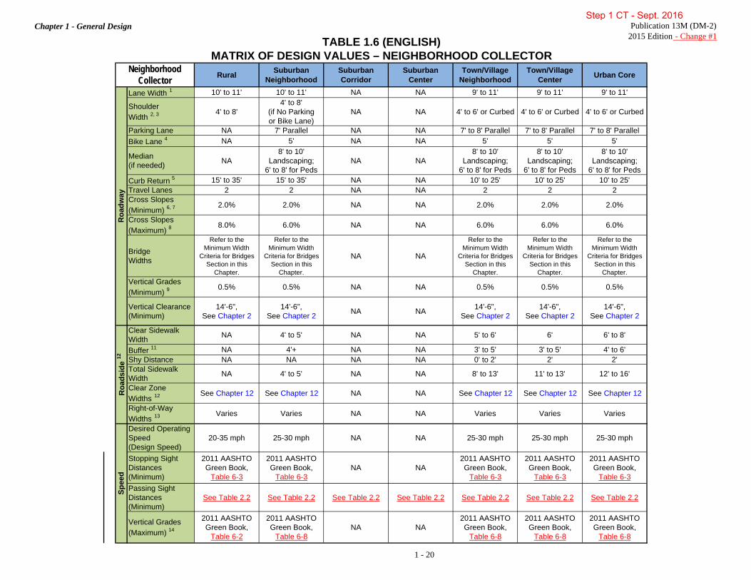
Chapter 1 - General Design Publication 13M (DM-2)2015 Edition - Change #1TABLE 1.6 (ENGLISH)
MATRIX OF DESIGN VALUES – NEIGHBORHOOD COLLECTORRural Suburban
NeighborhoodSuburban Corridor
SuburbanCenter
Town/Village Neighborhood
Town/Village Center Urban Core
Lane Width 1 10' to 11' 10' to 11' NA NA 9' to 11' 9' to 11' 9' to 11'
ShoulderWidth 2, 3 4' to 8'
4' to 8'(if No Parkingor Bike Lane)
NA NA 4' to 6' or Curbed 4' to 6' or Curbed 4' to 6' or Curbed
Parking Lane NA 7' Parallel NA NA 7' to 8' Parallel 7' to 8' Parallel 7' to 8' ParallelBike Lane 4 NA 5' NA NA 5' 5' 5'
Median(if needed) NA
8' to 10' Landscaping;
6' to 8' for PedsNA NA
8' to 10' Landscaping;
6' to 8' for Peds
8' to 10' Landscaping;
6' to 8' for Peds
8' to 10' Landscaping;
6' to 8' for PedsCurb Return 5 15' to 35' 15' to 35' NA NA 10' to 25' 10' to 25' 10' to 25'Travel Lanes 2 2 NA NA 2 2 2Cross Slopes (Minimum) 6, 7 2.0% 2.0% NA NA 2.0% 2.0% 2.0%
Cross Slopes (Maximum) 8
8.0% 6.0% NA NA 6.0% 6.0% 6.0%
BridgeWidths
Refer to the Minimum Width
Criteria for Bridges Section in this
Chapter.
Refer to the Minimum Width
Criteria for Bridges Section in this
Chapter.
NA NA
Refer to the Minimum Width
Criteria for Bridges Section in this
Chapter.
Refer to the Minimum Width
Criteria for Bridges Section in this
Chapter.
Refer to the Minimum Width
Criteria for Bridges Section in this
Chapter.Vertical Grades(Minimum) 9
0.5% 0.5% NA NA 0.5% 0.5% 0.5%
Vertical Clearance (Minimum)
14'-6",See Chapter 2
14'-6",See Chapter 2 NA NA 14'-6",
See Chapter 214'-6",
See Chapter 214'-6",
See Chapter 2
Clear Sidewalk Width NA 4' to 5' NA NA 5' to 6' 6' 6' to 8'
Buffer 11 NA 4'+ NA NA 3' to 5' 3' to 5' 4' to 6'Shy Distance NA NA NA NA 0' to 2' 2' 2'Total Sidewalk Width NA 4' to 5' NA NA 8' to 13' 11' to 13' 12' to 16'
Clear ZoneWidths 12 See Chapter 12 See Chapter 12 NA NA See Chapter 12 See Chapter 12 See Chapter 12
Right-of-Way Widths 13 Varies Varies NA NA Varies Varies Varies
Desired Operating Speed (Design Speed)
20-35 mph 25-30 mph NA NA 25-30 mph 25-30 mph 25-30 mph
Stopping Sight Distances(Minimum)
2011 AASHTO Green Book,
Table 6-3
2011 AASHTO Green Book,
Table 6-3NA NA
2011 AASHTO Green Book,
Table 6-3
2011 AASHTO Green Book,
Table 6-3
2011 AASHTO Green Book,
Table 6-3Passing Sight Distances(Minimum)
See Table 2.2 See Table 2.2 See Table 2.2 See Table 2.2 See Table 2.2 See Table 2.2 See Table 2.2
Vertical Grades(Maximum) 14
2011 AASHTO Green Book,
Table 6-2
2011 AASHTO Green Book,
Table 6-8NA NA
2011 AASHTO Green Book,
Table 6-8
2011 AASHTO Green Book,
Table 6-8
2011 AASHTO Green Book,
Table 6-8
NeighborhoodCollector
Roa
dway
Roa
dsid
e 12
Spee
d
1 - 20
Step 1 CT - Sept. 2016

Chapter 1 - General Design Publication 13M (DM-2) 2015 Edition - Change #1
1 - 21
TABLE 1.6 (ENGLISH) (CONTINUED) MATRIX OF DESIGN VALUES – NEIGHBORHOOD COLLECTOR
Step 1 CT - Sept. 2016

Chapter 1 - General Design Publication 13M (DM-2)2015 Edition - Change #1TABLE 1.7 (ENGLISH)
MATRIX OF DESIGN VALUES – LOCAL ROADRural Suburban
NeighborhoodSuburban Corridor
SuburbanCenter
Town/Village Neighborhood
Town/Village Center Urban Core
Lane Width 1 9' to 11' See Roadway Width NA NA See Roadway
Width 9' to 11' 9' to 11'
Roadway Width 2See Lane and
Shoulder Width
Wide: 34' to 36'Medium: 30'Narrow: 26'
Very Narrow: 20'
NA NA
Wide: 34' to 36'Medium: 30'Narrow: 26'
Very Narrow: 20'
See Lane and Parking Width
See Lane and Parking Width
ShoulderWidth 3 2' to 8' See Roadway
Width NA NA See Roadway Width 2' to 6' or Curbed 2' to 6' or Curbed
Parking Lane NA 7' Parallel NA NA 7' to 8' Parallel 7' to 8' Parallel 7' to 8' ParallelBike Lane 4 NA NA NA NA NA NA NAMedian NA NA NA NA NA NA NACurb Return 5 10' to 25' 10' to 25' NA NA 5' to 25' 5' to 25' 5' to 25'Travel Lanes 2 2 NA NA 2 2 2Cross Slopes (Minimum) 6, 7 2.0% 2.0% NA NA 2.0% 2.0% 2.0%
Cross Slopes (Maximum) 8 8.0% 6.0% NA NA 6.0% 6.0% 6.0%
Bridge Widths
Refer to the Minimum Width
Criteria for Bridges Section in this
Chapter.
Refer to the Minimum Width
Criteria for Bridges Section in this
Chapter.
NA NA
Refer to the Minimum Width
Criteria for Bridges Section in this
Chapter.
Refer to the Minimum Width
Criteria for Bridges Section in this
Chapter.
Refer to the Minimum Width
Criteria for Bridges Section in this
Chapter.Vertical Grades(Minimum) 9 0.5% 0.5% NA NA 0.5% 0.5% 0.5%
Vertical Clearance (Minimum)
14'-6",See Chapter 2
14'-6",See Chapter 2 NA NA 14'-6",
See Chapter 214'-6",
See Chapter 214'-6",
See Chapter 2
Clear Sidewalk Width NA 4' to 5' NA NA 5' 5' to 6' 6' to 8'
Buffer 11 NA 4'+ NA NA 3' to 5' 3' to 5' 3' to 5'Shy Distance NA NA NA NA 0' to 2' 2' 2'Total Sidewalk Width NA 4' to 5' NA NA 8' to 12' 10' to 13' 11' to 15'
Clear ZoneWidths 12 See Chapter 12 See Chapter 12 NA NA See Chapter 12 See Chapter 12 See Chapter 12
Right-of-Way Widths 13 Varies Varies NA NA Varies Varies Varies
Desired Operating Speed (Design Speed)
20-30 mph 20-25 mph NA NA 20-25 mph 20-25 mph 20-25 mph
Stopping Sight Distances(Minimum)
2011 AASHTO Green Book,
Table 5-3
2011 AASHTO Green Book,
Table 5-3NA NA
2011 AASHTO Green Book,
Table 5-3
2011 AASHTO Green Book,
Table 5-3
2011 AASHTO Green Book,
Table 5-3Passing Sight Distances(Minimum)
See Table 2.2 See Table 2.2 See Table 2.2 See Table 2.2 See Table 2.2 See Table 2.2 See Table 2.2
Vertical Grades(Maximum)
2011 AASHTO Green Book,
Table 5-28% to 15% 14 NA NA 8% to 15% 14 8% to 15% 14 8% to 15% 14
LocalRoad
Roa
dway
Roa
dsid
e 12
Spee
d
1 - 22
Step 1 CT - Sept. 2016

Chapter 1 - General Design Publication 13M (DM-2) 2015 Edition - Change #1
1 - 23
TABLE 1.7 (ENGLISH) (CONTINUED) MATRIX OF DESIGN VALUES – LOCAL ROAD
Step 1 CT - Sept. 2016

Chapter 1 - General Design Publication 13M (DM-2) 2015 Edition - Change #1
1 - 24
TABLE 1.8 (ENGLISH) MATRIX OF DESIGN VALUES – LIMITED ACCESS FREEWAY
Step 1 CT - Sept. 2016

Chapter 1 - General Design Publication 13M (DM-2) 2015 Edition - Change #1
1 - 25
TABLE 1.8 (ENGLISH) (CONTINUED) MATRIX OF DESIGN VALUES – LIMITED ACCESS FREEWAY
Step 1 CT - Sept. 2016

Chapter 1 - General Design Publication 13M (DM-2) 2015 Edition - Change #1
1 - 26
C. Minimum Width Criteria for Bridges. The minimum width of bridges shall be determined as described in this Section. The bridge width is the curb-to-curb, barrier-to-barrier or rail-to-rail width, whichever is less. The widths provided in this Section are based on two-lane roadways. The widths must be increased for each additional lane based on the applicable lane widths. For bridge design specifications including applicable design loads, refer to Publication 15M, Design Manual, Part 4, Structures and AASHTO LRFD Bridge Design Specifications.
1. Limited Access Freeway Facilities.
a. New, Reconstructed and Rehabilitated Bridges. This includes new location, replacement, superstructure replacement, partial superstructure replacement, deck replacement and partial deck replacement. The applicable minimum bridge widths are provided in Table 1.8.
b. Bridge Preservation and Safety Items. Bridge preservation is defined in Publication 15M, Design Manual, Part 4, Structures, Part A, Chapter 5, Article 5.6. Safety items may include repair and replacement of parapet and barrier as well as approach guide rail and connections. The bridge width is not to be reduced below existing width or new criteria provided in Table 1.8, whichever is less.
2. Arterial Facilities.
a. New and Reconstructed Bridges. This includes new location, replacement and superstructure replacement. The applicable minimum bridge widths are provided in Tables 1.3 and 1.4.
b. Deck Replacement and Partial Superstructure Replacement. The applicable minimum bridge widths are provided in Table 1.9. c. Bridge Preservation and Safety Items. Bridge preservation is defined in Publication 15M, Design Manual, Part 4, Structures, Part A, Chapter 5, Article 5.6. Safety items may include repair and replacement of parapet and barrier as well as approach guiderail and connections. The bridge width is not to be reduced below existing width, criteria provided in Tables 1.3, 1.4, 1.9 or 1.12 (if non-NHS), whichever is less.
3. Collector and Local Road Facilities.
a. New and Reconstructed Bridges. This includes new location, replacement and superstructure replacement. The applicable minimum bridge widths are provided in Table 1.11.
b. Deck Replacement and Partial Superstructure Replacement. The applicable minimum bridge widths are provided in Table 1.10.
c. Bridge Preservation and Safety Items. Bridge preservation is defined in Publication 15M, Design Manual, Part 4, Structures, Part A, Chapter 5, Article 5.6 Safety items may include repair and replacement of parapet and barrier as well as approach guiderail and connections. The bridge width is not to be reduced below existing width, criteria provided in Tables 1.10, 1.11, or 1.12 Width (if non-NHS), whichever is less.
INTENTIONALLY BLANK
Step 1 CT - Sept. 2016

Chapter 1 - General Design Publication 13M (DM-2) 2015 Edition - Change #1
1 - 27
TABLE 1.9
ARTERIAL FACILITIES DECK REPLACEMENT AND PARTIAL
SUPERSTRUCTURE REPLACEMENT (a)
CURRENT ADT
MINIMUM BRIDGE WIDTH
(METRIC) (m)
MINIMUM BRIDGE WIDTH
(ENGLISH) (ft)
400 and Under 9.0 30 401 to 1500 9.6 32 Over 1501 10.2 34
See Bridge Width Notes.
TABLE 1.10 COLLECTOR AND LOCAL ROAD FACILITIES
DECK REPLACEMENT AND PARTIAL SUPERSTRUCTURE REPLACEMENT (a)
CURRENT ADT
MINIMUM BRIDGE WIDTH
(METRIC) (m)
MINIMUM BRIDGE WIDTH
(ENGLISH) (ft)
400 and Under 7.2 (c) (e) 24 (c) (e) 401 to 1500 8.4 28
1501 to 2000 9.0 (f) 30 (f) Over 2000 10.2 (f) 34 (f)
See Bridge Width Notes.
TABLE 1.11 COLLECTOR AND LOCAL ROAD FACILITIES NEW AND RECONSTRUCTED BRIDGES (b)
DESIGN YEAR ADT
MINIMUM BRIDGE WIDTH
(METRIC) (m)
MINIMUM BRIDGE WIDTH
(ENGLISH) (ft)
400 and Under 7.2 (d) (e) 24 (d) (e) 401 to 1500 8.4 28
1501 to 2000 9.6 32 Over 2000 12.0 40
See Bridge Width Notes.
Step 1 CT - Sept. 2016

Chapter 1 - General Design Publication 13M (DM-2) 2015 Edition - Change #1
1 - 28
BRIDGE WIDTH NOTES The following notes are applicable to Tables 1.9, 1.10 and 1.11: • The lane widths plus the shoulder widths indicated in Table 1.3 through Table 1.7 may be considered for
bridge widths if they are less than the bridge width shown in Tables 1.9, 1.10 and 1.11.
• The bridge width is not to be less than the approach roadway width including shoulders with the exception of one-lane bridges and bridges over 60 m (200 ft) in length. On curbed approaches, the minimum bridge width may equal the approach curb-to-curb width. Where parking lanes are provided on the approaches, consideration should be given to extending the parking lanes across the bridge.
• Where pedestrian traffic is anticipated, provisions for a sidewalk should be considered and shall meet the Department's Standards and requirements (See Chapter 6 and Publication 15M, Design Manual, Part 4, Structures, Part B, Section 2, Article 2.3).
• When special conditions warrant, such as two-way traffic operations for future rehabilitation (repair or
overlay), consideration should be given to increased widths which may require additional girders.
• For bridges over 60 m (200 ft) in length, offsets to the parapet, rail, barrier or curb shall be at least 1.2 m (4 ft) from the travel lane on both the left and the right except where there are narrower curbed approaches or where a narrower width is permitted by the below notes.
The following notes are applicable as designated in Tables 1.9, 1.10 and 1.11: (a) If the bridge is not on the National Highway System (NHS), the minimum bridge width may be equal to the
bridge width provided in Table 1.12, Reduced Bridge Width. (b) If the conditions listed on the form in Chapter 1, Appendix A, Reduced Bridge Width Criteria Documentation
are met, the minimum bridge width may be equal to the bridge width provided in Table 1.12, Reduced Bridge Widths.
(c) On facilities functionally classified as a local road not on the NHS with no evidence of a site specific safety
problem related to the width of the bridge, the existing bridge width can remain. (d) On facilities functionally classified as a local road not on the NHS with a current average daily traffic (ADT)
of 250 and less and a design speed less than 60 km/h (40 mph), the minimum bridge width may be 0.6 m (2 ft) less than the value indicated.
(e) One-lane bridges:
• May be provided on single-lane roads and on two-lane roads with ADT less than 100 vehicles per day where the designer finds that a one-lane bridge can operate effectively.
• May be provided when there is an existing bridge in place that meets all of the following conditions: o The facility is functionally classified as a local road off the National Highway System o Has an ADT less than or equal to 400 o There is no evidence of a site-specific safety problem o There are no existing or anticipated significant land use conflicts exist
• The minimum width of a one-lane bridge is 4.5 m (15 ft) and the maximum width is 4.9 m (16 ft). • Alignment and sight distance should be carefully studied so that they are not compromised. Appropriate
safety mitigation measures should be provided (See Table 1.1, Low Cost Safety Improvement Measures). (f) For design speeds less than 80 km/h (50 mph), the minimum bridge widths may be 0.6 m (2 ft) less than the
values indicated.
Step 1 CT - Sept. 2016

Chapter 1 - General Design Publication 13M (DM-2) 2015 Edition - Change #1
1 - 29
TABLE 1.12
REDUCED BRIDGE WIDTHS
DESIGN YEAR ADT
DESIGN SPEED (km/h)
MINIMUM BRIDGE WIDTH(1)
(m)
DESIGN SPEED (mph)
MINIMUM BRIDGE WIDTH(1)
(ft)
≤ 400 < 80 6.6 < 50 22 > 80 7.2 > 50 24
401 to 1,000 < 80 7.2 < 50 24 > 80 7.8 > 50 26
1,001 to 2,000 < 80 7.8 < 50 26 > 80 8.4 > 50 28
2,001 to 4,000 < 80 8.4 < 50 28 > 80 9.0 > 50 30
4,001 to 10,000 < 80 9.0 < 50 30 > 80 9.6 > 50 32
10,001 to 20,000 < 80 9.6 < 50 32 > 80 10.2 > 50 34
≥ 20,000 ALL 10.2 ALL 34
(1) If the number of heavy vehicles exceeds 10% of the high end of the ADT range, then increase the minimum bridge width by 0.6 m (2 ft).
INTENTIONALLY BLANK
Step 1 CT - Sept. 2016

Chapter 1 - General Design Publication 13M (DM-2) 2015 Edition - Change #1
1 - 30
D. Shoulder Criteria for New Construction and Reconstruction Projects.
1. General. Any new construction or reconstruction project having a rigid pavement structure shall have Portland Cement Concrete shoulders provided. On any new construction or reconstruction project having a flexible pavement, the pavement shall be constructed 0.6 m (2 ft) wider into the shoulder area. The remainder of the shoulder shall be constructed with the type of shoulder designated below. The shoulder area is defined as the appropriate shoulder width indicated on the design criteria charts. The 0.6 m (2 ft) widening does not apply to the inside shoulders on Interstate and Other Limited Access Freeways. See Publication 72M, Roadway Construction Standards, RC-25M. Types 1-F, 1-S, 1-SP, 6-F, 6-S and 6-SP Shoulders have been developed primarily to provide smooth surfaces for bicyclists and pedestrians where it is anticipated such activities would take place. At the discretion of the District Executive, these types of shoulders may be provided elsewhere.
2. Provide Concrete Shoulders adjacent to rigid pavements. Concrete Shoulders, Type 1 shall be provided on Interstate and Other Limited Access Freeways. Concrete Shoulders, Type 2 shall be provided on Arterials, Collectors and Local Roads.
3. Provide Type 1, 1-F, 1-S or 1-SP Shoulders adjacent to flexible pavements in the following cases:
a. On all Interstate and Other Limited Access Freeways and Arterials. b. On other type roadways where serious drainage problems are anticipated. c. On two-lane roadways where truck traffic exceeds a Design Hourly Volume (DHV) of 150. d. On two-lane roadways where it is anticipated that traffic shall utilize the shoulder:
(1) At intersections with ramps having tight radii and roadways with curves having radii less than 140 m (curves sharper than 12°-30').
(2) At intersection approaches adjacent to the through movement where it is anticipated that left turn vehicles shall be causing vehicles wishing to proceed straight through to use the right side shoulder. In such cases, either the roadway pavement structure may be extended through the shoulder area or Type 1, 1-F or 1-S Shoulder may be used, starting 75 m (250 ft) before the intersection and stopping 45 m (150 ft) downstream from the intersection.
(3) For approaches to an intersection, where it is anticipated that right turning vehicles shall utilize the shoulder area as a turning lane, the shoulder area shall be paved with a Type 1, 1-F, 1-S or 1-SP Shoulder or the roadway pavement structure may be extended through the shoulder area. The length of higher type paving approaching the intersection shall be in accordance with the following chart:
RIGHT TURNING
VEHICLES/h <100 100 TO 200
>200
MIN LENGTH 30 m (100 ft)
55 m (175 ft)
75 m (250 ft)
(4) At other locations at the discretion of the Engineer.
4. Provide Type 3 Shoulders adjacent to flexible pavements on Collectors and Local Roads of the same surface material as the pavement structure or provide Type 1, 1-F, 1-S or 1-SP Shoulders.
5. For proper application of bicycle tolerable shoulder rumble strips and edge line rumble strips, see Publication 638, District Highway Safety Guidance Manual. Refer to Publication 72M, Roadway Construction Standards, RC-25M for standard rumble strips.
Step 1 CT - Sept. 2016

Chapter 1 - General Design Publication 13M (DM-2) 2015 Edition - Change #1
1 - 31
E. Design Criteria for Resurfacing, Reconstruction and Rehabilitation (3R) Projects.
1. Refer to Section 1.2.A to determine if 3R criteria is applicable to a project. Design criteria for 3R projects are provided in Table 1.13, Table 1.14 and associated notes. Shoulder criteria notes are found in Section 1.2.E.2.
TABLE 1.13
RESURFACING, RESTORATION AND REHABILITATION (3R) DESIGN CRITERIA*
RURAL AREA SYSTEM URBAN AREA SYSTEM DESIGN SPEED (km/h or mph) SEE NOTE SEE NOTE
PAVEMENT WIDTHS SEE TABLE 1.14 3.6 m (12 ft) LANES (DESIRABLE) 3.0 m (10 ft) LANES (MINIMUM)
SHOULDER WIDTHS SEE TABLE 1.14 EXISTING MEDIAN WIDTHS EXISTING EXISTING
CROSS SLOPES
TANGENT: 2.0% (DESIRABLE) 1.0% (MINIMUM) WHERE
GRADES ARE ≥ 1% SUPERELEVATION: SEE NOTE
EXISTING
VERTICAL CURVATURE AND GRADES EXISTING EXISTING
HORIZONTAL CURVATURE EXISTING EXISTING SIGHT DISTANCES EXISTING EXISTING GUIDE RAIL AND MEDIAN BARRIER SEE NOTE SEE NOTE
CLEAR ZONE WIDTHS SEE CHAPTER 12 SEE CHAPTER 12 BRIDGE WIDTHS SEE SECTION 1.2.C SEE SECTION 1.2.C
PARKING LANES NONE SEE CHAPTER 1, TABLE 1.3 THROUGH TABLE 1.7
VERTICAL CLEARANCE SEE CHAPTER 2, SECTION 2.20 SEE CHAPTER 2, SECTION 2.20
SEE 3R DESIGN CRITERIA NOTES ON PAGES 1 - 34 AND 1 - 35. *3R criteria is not applicable for freeways. For freeways, use New Construction and Reconstruction criteria or Pavement Preservation criteria, as applicable.
INTENTIONALLY BLANK
Step 1 CT - Sept. 2016

Chapter 1 - General Design Publication 13M (DM-2) 2015 Edition - Change #1
1 - 32
TABLE 1.14 MINIMUM WIDTH CRITERIA
FOR RESURFACING, RESTORATION AND REHABILITATION (3R) RURAL PROJECTS (a)
Step 1 CT - Sept. 2016

Chapter 1 - General Design Publication 13M (DM-2) 2015 Edition - Change #1
1 - 33
Step 1 CT - Sept. 2016

Chapter 1 - General Design Publication 13M (DM-2) 2015 Edition - Change #1
1 - 34
RESURFACING, RESTORATION AND REHABILITATION (3R) DESIGN CRITERIA NOTES
When the project scope does not include an overlay or a roadway geometry improvement (e.g., drainage, guide rail, shoulder structural upgrading, etc.), a design speed is not applicable to the project. If an overlay or a roadway geometry improvement (e.g., pavement or shoulder widening, increase in superelevation, etc.) is included in the project scope, a design speed shall be used. The minimum design speed selected shall be equal to the average running speed plus any anticipated increase in the average running speed due to the overlay or roadway geometry improvement, rounded upward to the nearest 10 km/h (5 mph) increment (the average running speed, which represents the length of the highway segment divided by the average running time, i.e., the time the vehicle is in motion along the segment, shall be determined as set forth in Publication 212, Official Traffic Control Devices. The maximum design speed selected shall be based on the applicable functional classification systems indicated in Chapter 1, Table 1.3 through Table 1.8. The design speed selected may be a range of speeds based upon the governing speed in each subsection of the project.
Major urban arterial streets and highways with
some access control and fairly long distances between intersections should have a design speed determined according to Note . However, those major arterials that have obvious "street-like" characteristics, operationally and physically, and most urban, local and collector streets do not require a design speed determination.
Where the existing widths are greater than those
indicated in the criteria, maintain the existing widths.
Railroad grade crossing paving shall extend 0.6 m
(2 ft) beyond the extreme rails for the full graded width of the highway.
Lanes 2.7 m (9 ft) wide may be used on one-way
streets or for divided roadways if at least a 0.3 m (1 ft) curb offset is used or if trucks and buses are prohibited.
Curb Offset: 60 km/h (40 mph) and Less - None Greater Than 60 km/h (40 mph) - 0.3 m (1 ft)
desirable
In cut sections, on widening or reconstruction projects, where the width available from the edge of pavement to the toe of the cut slope is 2.4 m (8 ft) or less, the shoulder paving should be extended to the toe of the cut slope. Where this width is variable, the shoulder paving may also be variable. If erosion is a problem in this area, consideration should be given to extending the paving 250 mm to 300 mm (10 in to 12 in) up the slope.
Use Rural 3R Design Criteria if uncurbed section is
used in urban areas.
In order to increase the amount of drainage capacity or to include reconstruction of the shoulder, the shoulder cross slopes may be increased as indicated in Note .
When the actual rate of superelevation is within
3.0% of the design superelevation rate, it is not necessary to increase the superelevation rate. When the actual rate of superelevation differs by more than 3.0% from the design superelevation rate, the highest achievable rate should be provided. When the curve superelevation provided does not equal the design superelevation rate, warning signs with advisory speed plates shall be provided. A reduction of the required superelevation rate is acceptable when short tangents between reverse curves do not afford sufficient runout length after consideration to partial runout within the curves. Rates of superelevation and the design speed shall be considered jointly. See Note for additional information relative to design speed.
Since superelevation is not always possible, more
attention should be paid to other items such as friction overlays and signing and pavement marking. For additional information, see Notes and .
Step 1 CT - Sept. 2016

Chapter 1 - General Design Publication 13M (DM-2) 2015 Edition - Change #1
1 - 35
RESURFACING, RESTORATION AND REHABILITATION (3R) DESIGN CRITERIA NOTES
GENERAL: Existing horizontal curvature, vertical curvature and grades and sight distance shall be evaluated against minimum criteria for the design speed. For sites with accident experience, an economic analysis shall be made to determine feasibility for reconstruction. If reconstruction is not feasible, or reconstruction is less than new construction standards, a design exception request shall be prepared. In addition, appropriate safety and other mitigation measures shall be applied to enhance and upgrade these geometric features for extended service life and safer operations. See Chapter 1, Table 1.1 for a list of low cost safety improvement measures as alternates to reconstruction.
HORIZONTAL CURVATURE: When the design
speed of a horizontal curve is 25 km/h (15 mph) or less below the design speed of the proposed project and no accident problem is prevalent, warning signs with advisory speed plates shall be provided. Also, the list of low cost safety improvement measures in Chapter 1, Table 1.1 shall be considered. When the difference is greater than 25 km/h (15 mph) and the current average daily traffic (ADT) is 750 or greater, or an accident problem exists, or the design speed of the horizontal curve is less than 30 km/h (20 mph), achievement of the design speed curvature criteria shall be considered through an economic analysis to determine feasibility for reconstruction. If reconstruction to current standards is not feasible, a design exception request shall be prepared. The design speed and rates of superelevation shall be considered jointly. See Note for additional information relative to superelevation rates.
VERTICAL CURVATURE AND GRADES:
When the design speed of a vertical curve is 30 km/h (20 mph) or less below the design speed of the proposed project, and no accident problem is prevalent, consider the list of low cost safety improvement measures in Chapter 1, Table 1.1. When the difference is greater than 30 km/h (20 mph) and the current average daily traffic (ADT) is 1500 or greater, or an accident problem exists, or the design speed of the vertical curve is less than 30 km/h (20 mph), consider achievement of the design speed curvature criteria and grades through an economic analysis to determine feasibility for reconstruction. Prepare a request for a design exception if reconstruction to current standards is not feasible.
SIGHT DISTANCE: When evaluating sight distance parameters, consider the preceding criteria on horizontal and vertical curvature together.
Remove existing guide rail and median barrier
where not required especially if it does not comply with NCHRP Report 350. Consider slope flattening to eliminate need. Provide upgraded guide rail at bridge approaches and at identifiable accident locations. Replace existing metal guide rail and metal median barrier where the height of the existing barrier after resurfacing is reduced by more than 75 mm (3 in) from the standard height and cannot be raised. Raising the guide rail with modified offset brackets is not permitted. In order to avoid the requirement to replace or adjust guide rail or median barrier, the shoulder slope may be increased to a maximum algebraic difference in pavement and shoulder slopes of 8.0% for shoulders greater than 1.8 m (6 ft) wide, 10.0% for shoulders 1.2 m to 1.8 m (4 ft to 6 ft) wide, 12.0% for shoulders 0.9 m to 1.2 m (3 ft to 4 ft) wide or 14.0% for shoulders 0.6 m to 0.9 m (2 ft to 3 ft) wide.
Step 1 CT - Sept. 2016

Chapter 1 - General Design Publication 13M (DM-2) 2015 Edition - Change #1
1 - 36
2. Shoulder Criteria for Resurfacing, Reconstruction and Rehabilitation (3R) Projects.
a. Without Pavement Widening.
(1) On projects involving the rehabilitation of rigid pavement, concrete shoulders may be provided, if desired, to strengthen the existing pavement or provide a relatively maintenance-free shoulder. Special drawings would be required in such cases. At no time shall the joint spacing of the concrete shoulders exceed 6.0 m (20 ft). (2) Provide Type 6, 6-F, 6-S or 6-SP Shoulders on Interstate and Other Limited Access Freeways and Arterials where excavation or scarifying of the existing shoulder is necessary. If the existing shoulder is currently high-type paved (stabilized excluded), and only the first couple of meters (first few feet) adjacent to the pavement is distressed, a 0.9 m (3 ft) minimum width of Type 6, 6-F, 6-S or 6-SP Shoulder may be provided. The remaining existing shoulder should be resurfaced with the same surfacing used on the new shoulder. (3) Provide Type 7 Shoulders on Interstate and Other Limited Access Freeways and Arterials where only cleaning and patching of the existing paved shoulder is necessary. (4) Provide shoulders adjacent to flexible pavements on Collectors and Local Roads of the same surface material as the pavement structure, or provide Type 1, 1-F, 1-S or 1-SP Shoulders.
b. With Pavement Widening.
(1) On projects where the pavement is being widened and the current traffic ADT is greater than 5000 and/or the number of heavy vehicles (Current Traffic ADT × % of trucks, buses and recreational vehicles) is greater than 500, the widening structure shall be extended into the shoulder area 0.6 m (2 ft), similar to that required for new construction. When the current traffic ADT is 5000 or less and/or the number of heavy vehicles is 500 or less, the widening structure shall be extended 0.3 m (1 ft) into the shoulder area. The entire shoulder may be paved with the same material and design as the pavement widening at the discretion of the District Executive. In areas of heavy turning movement, such as driveway entrances or exits, intersections, etc., paving out-to-out is strongly recommended. Otherwise, the type of shoulder discussed in Sections 1.2.E.2.a(1), 1.2.E.2.a(2) and 1.2.E.2.a(3) above should be specified. (2) The widening portion of the pavement should be constructed at the same slope as the pavement. The shoulder slope should begin at the edge of the widened pavement. When the pavement structure is being extended for the full width of the shoulder, the shoulder slope should begin at the design width of pavement. Typical sections should indicate the shoulder area in these cases even though the materials used may be paid for separately. (3) The 0.3 m (1 ft) or 0.6 m (2 ft) widening in Section 1.2.E.2.b(1) above may be eliminated on Arterials with less than 5000 ADT and on Collectors and Local Roads if the optional shoulder described in Section 1.2.E.2.a(4) above is used or if a Type 6, 6-F, 6-S, 6-SP or 7 Shoulder or a recycled shoulder is provided for the entire width of shoulder.
c. Recycled Shoulders on 3R Projects.
(1) The use of reclaimed bituminous concrete material, which is generally obtained from milling operations, for shoulder base courses, is acceptable on 3R projects. Refer to Publication 242, Pavement Policy Manual, Chapter 2, Project Considerations for guidelines for recycling bituminous pavements. (2) Reclaimed material may be used in a hot-mixed recycled base course for Type 6, 6-F, or 6-S Shoulders or hot-mixed surface course for Type 7 shoulders on any roadway.
Step 1 CT - Sept. 2016

Chapter 1 - General Design Publication 13M (DM-2) 2015 Edition - Change #1
1 - 37
(3) Reclaimed material may be used in a cold-mixed recycled base course in the shoulders of Arterials, Collectors and Local Roads. A minimum depth of 130 mm (5 in) shall be used on Arterials and 100 mm (4 in) on Collectors and Local Roads.
1.3 PAVEMENT PRESERVATION CRITERIA Refer to Publication 242, Pavement Policy Manual for determining when Pavement Preservation criteria is applicable to a project. Typically pavement projects which do not add structural capacity to the pavement are pavement preservation type projects. Safety guidance in Publication 242, Pavement Policy Manual shall be met, including evaluating the crash history to identify safety concerns, and all identified safety concerns are to be addressed as applicable. For example, widening of the traveled way on horizontal curves may be necessary to address a safety concern. The following is the geometric criteria for pavement preservation projects. The proposed geometric design elements shall be compared to the required criteria presented below, and a design exception is required if any of the 13 controlling criteria is not met (defined in Publication 10X, Design Manual Part 1X, Appendices to Design Manuals 1, 1A, 1B, and 1C, Appendix P, Design Exceptions). If non-controlling criteria is not met, some form of documentation must be provided. Documentation may include meeting minutes or Design Field View Reports, etc. A. Non-Freeway Criteria.
1. Cross Slopes of Lanes in Tangent Sections. a. Rural Classification. Desirable = 2.0%. Minimum = 1.0%. For existing cross slopes between 1.0% and 2.0%, do not reduce below existing. b. Urban Classification.
(1) Curbed Roadways. Desirable = 2.0% to 3.0%. Minimum = match existing. Address drainage issues. (2) Non-Curbed Roadways. Same as rural criteria.
2. Vertical Clearance Criteria. Refer to Chapter 2, Section 2.20.
3. All Other Controlling Criteria.
• Existing geometric elements not meeting New and Reconstruction Criteria are not to be adversely
affected.
• Existing geometric elements that meet or exceed New and Reconstruction Criteria are not to be affected to the extent of not meeting New and Reconstruction Criteria.
B. Freeway Criteria.
1. Cross Slopes in Tangent Sections.
a. Lanes. Desirable = 2.0%. Minimum = 1.5%. Maximum = 3.0%. For existing cross slopes between 1.5% and 2.0%, do not reduce below existing. b. Shoulders. Maximum = 8.0%.
2. Cross slope in superelevated sections:
Step 1 CT - Sept. 2016

Chapter 1 - General Design Publication 13M (DM-2) 2015 Edition - Change #1
1 - 38
a. Maximum. 8.0% algebraic cross slope difference in lane/shoulder cross slope. If the algebraic difference in cross slope is greater than 8.0%, then provide rounding as per DM-2, Section 1.5, typical section detail. b. Required superelevation and superelevation transition rate is to meet the statements provided below for the other controlling criteria.
3. Vertical Clearance Criteria. Refer to Chapter 2, Section 2.20.
4. All Other Controlling Criteria.
• Existing geometric elements not meeting New and Reconstruction Criteria are not to be adversely
affected.
• Existing geometric elements that meet or exceed New and Reconstruction Criteria are not to be affected to the extent of not meeting New and Reconstruction Criteria.
1.4 THIS SECTION IS INTENTIONALLY LEFT BLANK 1.5 TYPICAL ROADWAY CROSS SECTIONS The Typical Roadway Cross Section details contained in this section shall be used in the design of typical sections for new construction and reconstruction highway construction projects. For Limited Access Freeways (Interstate and Non-Interstate), the design values for cross sectional elements, as presented in Table 1.8, are intended primarily for reconstruction projects. For Arterials, Collectors, and Local Roads, the design values for cross sectional elements, as presented in Table 1.3 through Table 1.7, are intended primarily for reconstruction projects. For Arterials, Collectors, and Local Roads, when designing 3R projects, cross sectional elements shall be designed using the 3R Design Criteria as presented in Section 1.2.
INTENTIONALLY BLANK
Step 1 CT - Sept. 2016

Chapter 1 - General Design Publication 13M (DM-2) 2015 Edition - Change #1
1 - 39
BLANK PAGE
Step 1 CT - Sept. 2016

Chapter 1 - General Design Publication 13M (DM-2) 2015 Edition - Change #1
1 - 40
Step 1 CT - Sept. 2016

Chapter 1 - General Design Publication 13M (DM-2) 2015 Edition - Change #1
1 - 41
Step 1 CT - Sept. 2016
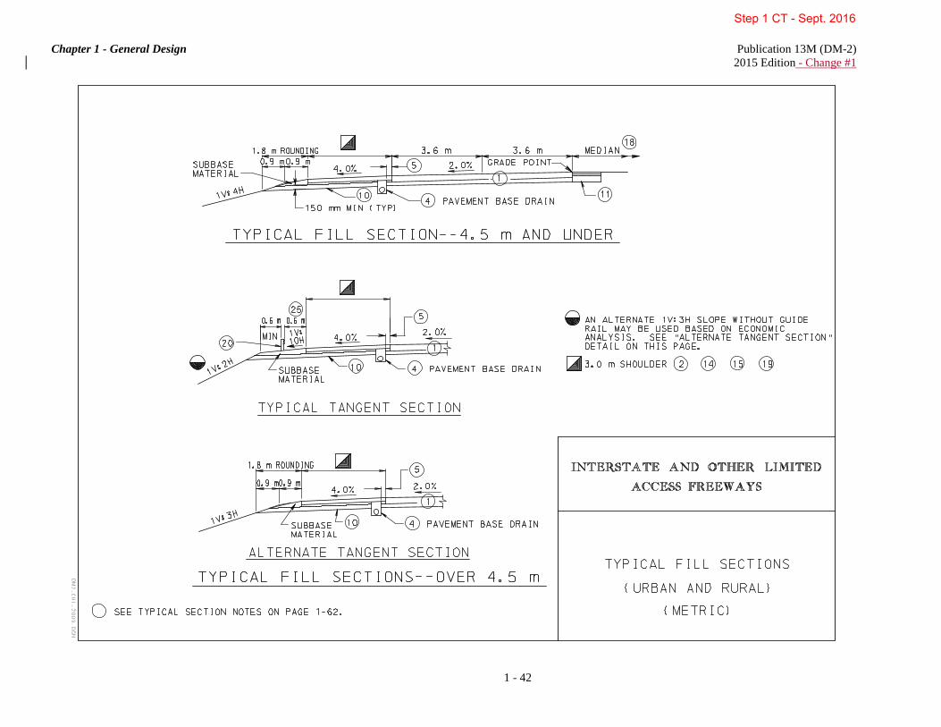
Chapter 1 - General Design Publication 13M (DM-2) 2015 Edition - Change #1
1 - 42
Step 1 CT - Sept. 2016

Chapter 1 - General Design Publication 13M (DM-2) 2015 Edition - Change #1
1 - 43
Step 1 CT - Sept. 2016

Chapter 1 - General Design Publication 13M (DM-2) 2015 Edition - Change #1
1 - 44
Step 1 CT - Sept. 2016

Chapter 1 - General Design Publication 13M (DM-2) 2015 Edition - Change #1
1 - 45
Step 1 CT - Sept. 2016

Chapter 1 - General Design Publication 13M (DM-2) 2015 Edition - Change #1
1 - 46
Step 1 CT - Sept. 2016

Chapter 1 - General Design Publication 13M (DM-2) 2015 Edition - Change #1
1 - 47
Step 1 CT - Sept. 2016

Chapter 1 - General Design Publication 13M (DM-2) 2015 Edition - Change #1
1 - 48
Step 1 CT - Sept. 2016

Chapter 1 - General Design Publication 13M (DM-2) 2015 Edition - Change #1
1 - 49
Step 1 CT - Sept. 2016

Chapter 1 - General Design Publication 13M (DM-2) 2015 Edition - Change #1
1 - 50
Step 1 CT - Sept. 2016

Chapter 1 - General Design Publication 13M (DM-2) 2015 Edition - Change #1
1 - 51
Step 1 CT - Sept. 2016

Chapter 1 - General Design Publication 13M (DM-2) 2015 Edition - Change #1
1 - 52
Step 1 CT - Sept. 2016

Chapter 1 - General Design Publication 13M (DM-2) 2015 Edition - Change #1
1 - 53
Step 1 CT - Sept. 2016

Chapter 1 - General Design Publication 13M (DM-2) 2015 Edition - Change #1
1 - 54
Step 1 CT - Sept. 2016
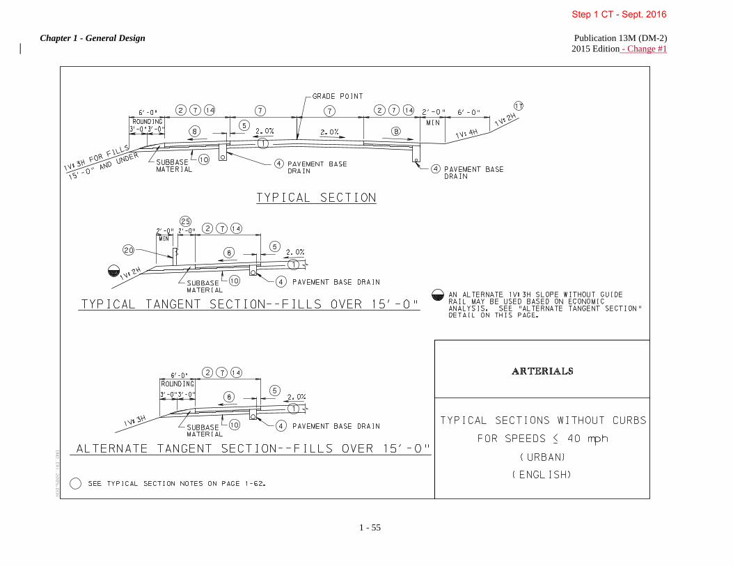
Chapter 1 - General Design Publication 13M (DM-2) 2015 Edition - Change #1
1 - 55
Step 1 CT - Sept. 2016

Chapter 1 - General Design Publication 13M (DM-2) 2015 Edition - Change #1
1 - 56
Step 1 CT - Sept. 2016

Chapter 1 - General Design Publication 13M (DM-2) 2015 Edition - Change #1
1 - 57
Step 1 CT - Sept. 2016

Chapter 1 - General Design Publication 13M (DM-2) 2015 Edition - Change #1
1 - 58
Step 1 CT - Sept. 2016

Chapter 1 - General Design Publication 13M (DM-2) 2015 Edition - Change #1
1 - 59
Step 1 CT - Sept. 2016

Chapter 1 - General Design Publication 13M (DM-2) 2015 Edition - Change #1
1 - 60
Step 1 CT - Sept. 2016

Chapter 1 - General Design Publication 13M (DM-2) 2015 Edition - Change #1
1 - 61
Step 1 CT - Sept. 2016

Chapter 1 - General Design Publication 13M (DM-2) 2015 Edition - Change #1
1 - 62
TYPICAL ROADWAY CROSS SECTION NOTES
See Publication 242, Pavement Policy Manual, for pavement design.
See Design Criteria Notes for type of shoulder. For all new construction or reconstruction projects, refer to Publication 72M, Roadway Construction Standards, RC-25M, for shoulder cross sections.
The shoulder on the low side of a superelevated section shall be sloped at the same rate as the travel lane when
the rate of travel lane slope exceeds the required shoulder slope of 4.0% or 6.0%. The shoulder cross slope may match the cross slope of the travel lane when the shoulder width is less than or equal to 3.0 ft.
Provide Pavement Base Drain in cuts and fills on all Interstate and Other Limited Access Freeways and
Arterials. On Collectors and Local Roads, Pavement Base Drains shall be used only where subbase cannot be outletted. Where subsurface water is a potential problem, Underdrain or Combination Storm Sewer shall be used. Where the subbase cannot be outletted, the subgrade slope shall be in the direction of, and at the same rate as, the shoulder slope and the "ALTERNATE SUBSURFACE DRAINAGE TREATMENT" on Pages 1 - 40 and 1 - 41 shall be used.
The distance from the edge of the pavement shall be equal to the subbase depth.
Special consideration shall be given to the median treatment on the approach to structures to insure the
elevation of the edges of the structure division are the same. This shall apply to medians up to 9.0 m (30 ft) on superelevated sections. Adequate length for shoulder slope transition between the roadway cross section and structure cross section should be provided.
See Design Criteria for widths of travel lanes and shoulders.
Slope shoulder at 6.0% for shoulder widths less than or equal to 2.4 m (8 ft). Slope shoulder at 4.0% for
shoulder widths greater than 2.4 m (8 ft). The shoulder cross slope may match the cross slope of the travel lane when the shoulder width is less than or equal to 3.0 ft. When the roadway shoulder cross slope is different than the bridge shoulder slope, transition the roadway shoulder slope (7.5 m (25 ft) minimum) approaching the structure, to meet the slope of the bridge water table.
A 1V:12H slope may be adjusted to a 1V:6H slope to provide 150 mm (6 in) minimum clearance from bottom
of swale to subgrade.
Subgrade slope shall be 1.0% minimum to shoulder slope maximum. For ease of construction, the subgrade slope under the shoulder area shall generally be the same as the pavement slope. A minimum subbase depth of 150 mm (6 in) shall be maintained under the outside of the shoulder, as shown on the "TYPICAL CUT SECTION" detail on Pages 1 - 40 and 1 - 41, or as shown on the "TYPICAL FILL SECTION - 4.5 m (15'-0") AND UNDER" detail on Pages 1 - 42 and 1 - 43.
Subgrade slope shall be in the direction of, and at the same rate as, the pavement slope. The depth of the
subbase under the outside edge of the shoulder shall be as shown on the "TYPICAL MEDIAN TREATMENT" detail on Pages 1 - 40 and 1 - 41.
A curb or a combination curb and gutter section may be installed at the outside edge of a parking lane,
although an offset of 0.3 m to 0.6 m (1 ft to 2 ft) is preferable. If a curb is to be installed where no parking lane is specified, provide a curb offset of 0.6 m (2 ft) desirable, 0.3 m (1 ft) minimum; it may be desirable to provide full width of shoulder as per Design Criteria in Tables 1.3 through 1.8, Matrix of Design Values.
Step 1 CT - Sept. 2016

Chapter 1 - General Design Publication 13M (DM-2) 2015 Edition - Change #1
1 - 63
TYPICAL ROADWAY CROSS SECTION NOTES
(Continued)
Maintain a minimum depth of 0.75 m (2 ft, 6 in) below the outside edge of shoulder or 150 mm (6 in) below top of subgrade, whichever is lower. Where it is not practical to construct a sufficiently deep swale, a Combination Storm Sewer and Underdrain should be constructed along the ditch line. The minimum depth of the Combination Storm Sewer and Underdrain will be either 300 mm (12 in) below the ditch line invert measured to the top of the pipe's bell or 150 mm (6 in) below the grade of the immediately adjacent subgrade, also measured to the top of the pipe's bell, whichever is lower. Provide a minimum of 150 mm (6 in) of tamped soil with appropriate Seeding and Soil Supplements placed over the Combination Storm Sewer and Underdrain.
Where subbase cannot be outletted, the pavement base drain shall be installed as indicated on the "ALTERNATE SUBSURFACE DRAINAGE TREATMENT" detail on Pages 1 - 40 and 1 - 41.
For new construction or reconstruction projects having a flexible pavement, see Pages 1 - 60 and 1 - 61 for
typical pavement widening into the shoulder area.
For shoulder treatment in superelevated sections, see TYPICAL SUPERELEVATED SECTIONS detail on Pages 1 - 50 and 1 - 51.
Pavement widening on the low side of superelevations shall be constructed as shown on the "TYPICAL
TANGENT SECTION" detail on Pages 1 - 60 and 1 - 61 with the rate of pavement widening the same as the superelevation rate.
Cut slope shall be 1V:2H unless otherwise indicated in the soil survey report.
For median treatment, see "TYPICAL MEDIAN TREATMENT" detail on Pages 1 - 40 and 1 - 41.
For shoulder treatment when the DDHV is equal to or greater than 250 Trucks, see Pages 1 - 46 and 1 - 47.
For guide rail type and clear zone criteria, refer to Chapter 12.
For slope treatment in cut and fill sections, see Pages 1 - 40, 1 - 41, 1 - 42 and 1 - 43.
For shoulder rounding details when superelevation is greater than 6.0%, see Pages 1 - 50 and 1 - 51.
For slope treatment, see Pages 1 - 56 and 1 - 57 for ARTERIALS and Pages 1 - 60 and 1 - 61 for
COLLECTORS AND LOCAL ROADS.
Where subbase cannot be outletted, the pavement base drain shall be installed as indicated on the "ALTERNATE SUBSURFACE DRAINAGE TREATMENT" detail on Pages 1 - 40 and 1 - 41.
When there are roadside barriers, walls, or other vertical elements, it is desirable to provide a graded shoulder
wide enough that the vertical elements will be offset a minimum of 0.6 m (2 ft) from the edge of the usable shoulder.
Step 1 CT - Sept. 2016

Chapter 1 - General Design Publication 13M (DM-2) 2015 Edition - Change #1
1 - 64
1.6 ACCELERATION AND DECELERATION (SPEED-CHANGE)AUXILIARY LANES The term speed-change lane, acceleration lane or deceleration lane, as used herein, applies broadly to the added pavement joining the traveled way of the highway with that of the turning roadway and does not necessarily imply a definite lane of uniform width. An auxiliary lane, including the tapered area, serves as a speed-change lane primarily for the acceleration or deceleration of vehicles entering or leaving the through-traffic lanes. An auxiliary lane should be of sufficient width and length to enable a driver to maneuver a vehicle into it properly, and once in it, to reduce speed from the speed of operation on the highway or street to the lower speed on the turning roadway or increase speed from the speed of the turning roadway to the higher speed of operation of the highway or street. The wWarrants for the use of speed-changeauxiliary lanes cannot be stated definitely. However, based on observations and past experience, the following general conclusions have been made:
1. Speed-changeAuxiliary lanes are warranted on high-speed and on high-volume highways where a change in speed is necessary for vehicles entering or leaving the through-traffic lanes.
2. All drivers do not use speed-changeauxiliary lanes in the same manner.
3. Use of speed-changeauxiliary lanes varies with volume, the majority of drivers using them at high volumes.
4. The directional type of speed-changeauxiliary lane consisting of a long taper fits the behavior of most drivers and does not require maneuvering on a reverse-curve path.
5. Deceleration lanes on the approaches to intersections that also function as storage lanes for turning traffic are particularly advantageous and experience with them generally has been favorable.
For additional information on speed-changeauxiliary lanes as applicable to intersections and interchanges, refer to Chapter 3 and Chapter 4 and to the 20042011 AASHTO Green Book, Chapter 9 and Chapter 10. 1.7 CONTROL OF ACCESS Regulating access is called access control and is achieved through full control of access, partial control of access, access management, and driveway/entrance regulations of public access rights to and from properties abutting the highway facilities. The principal advantages of controlling access are the preservation or improvement of service and safetythe reduction of crash frequency and severity. The functional advantage of providing access control on a street or highway is the management of the interference with through traffic by vehicles or pedestrians entering, leaving and crossing the highway. Where access to a highway is managed, entrances and exits are located at points best suited to fit traffic and land-use needs and are designed to enable vehicles to enter and leave safelythe highway with minimum interference from through traffic. On streets or highways where there is no access management and roadside businesses are allowed to develop haphazardly, interference from the roadside can become a major factor in reducing the capacity, increasing the crash potential and eroding the mobility function of the facility. Full control of access is the most important single safety factor that may be designed into new highways. The extent and degree of access control that is feasible or ultimately possible are significant factors in defining the type of street or highway. The following principles define access management techniques:
1. Classify the road system by the primary function of each roadway. Freeways emphasize movement and provide complete control of access. Local streets emphasize property access rather than traffic movement. Arterial and collector roads must serve a combination of both property access and traffic movement.
2. Limit direct access to roads with higher functional classifications. Direct property access should be denied or limited along higher class roadways, whenever reasonable access can be provided to a lower class roadway.
Step 1 CT - Sept. 2016

Chapter 1 - General Design Publication 13M (DM-2) 2015 Edition - Change #1
1 - 65
3. Locate traffic signals to emphasize through traffic movements. Signalized access points should fit into the overall signal coordination plan for traffic progression.
4. Locate driveways and major entrances to minimize interference with traffic operations. Driveways and entrances should be located away from other intersections to minimize crashes, to reduce traffic interference, and to provide for adequate storage lengths for vehicles turning into entrances.
5. Use curbed medians and locate median openings to manage access movements and minimize conflicts. The extent of access management depends upon the location, type and density of development, and the nature of the highway system. Access management actions involve both the planning and design of new roads and the retrofitting of existing roads and driveways. Access control on collector roads and streets should allow access to abutting properties consistent with the Level of Service desired. The control of access on urban collectors should be used primarily to ensure that access points conform to the adopted criteria for safety, location, design, construction and maintenance. An important consideration in arterial development is the amount of access control, full or partial, that can be acquired. Although adequate access can normally be provided without interference to traffic operations, unique problems may be encountered in the form of slow-moving pieces of machinery. Therefore, access points should be situated to minimize their detrimental effects while the appropriate degree of access control or access management depends on the type and importance of an arterial. Provision of access management is vital to the concept of an arterial route if it is to provide the service life for which it is designed. Adequate and uniform spacing between access points should be considered in relationship to intersection sight distance restrictions and other intersections. This may help eliminate many conditions where a large vehicle at an intersection hides another vehicle on a nearby approach. High-volume access points can lead to particular operational problems if not properly situated. Access control and access management on urban arterials should be carefully regulated to limit the number of points and their locations. Access control may be exercised (1) by statutory control which limits access to the cross streets or to other major traffic generators, (2) by zoning regulations which effectively control the type of property development along an arterial and influence the type and volume of traffic generated, (3) by driveway regulations to effectively preserve the functional character of the arterial and (4) by geometric highway design through the use of frontage roads; grade separations; limiting, prohibiting, or relocating left turns in and out of adjacent properties; and right-turn-in and right-turn-out arrangements. These geometric highway design measures effectively control access to the through lanes on the arterial street, provide access to adjoining property, separate local from through traffic and permit circulation of traffic along each side of the arterial. For Interstate and Other Limited Access Freeways, with full control access, preference is given to through traffic by providing access connections with selected public roads only and by prohibiting crossings at-grade and direct private driveway connections. The principal advantages of access control include preservation of highway capacity, higher speeds, and improved safety for highway users. Access to the interstate system shall be fully controlled. The interstate highway shall be grade separated at all railroad crossings and selected public crossroads. At-grade intersections shall not be allowed. To accomplish this, the intersecting roads are to be grade separated, terminated, rerouted, and/or intercepted by frontage roads. Access is to be achieved by interchanges at selected public roads. On all sections of the Interstate System, access shall be controlled by acquiring access rights outright prior to construction or by the construction of frontage roads or both. Control of access is required for all sections of the Interstate System, including the full length of ramps and terminals on the crossroad. Control for connections to the crossroad should be affected beyond the ramp terminals by purchasing of access rights, providing frontage roads to control access, controlling added corner right-of-way areas or denying driveway permits. Such control should extend along the crossroads beyond the ramp terminal at least 30 m (100 ft) or more in urban areas and at least 90 m (300 ft) or more in rural areas. These distances usually should satisfy any congestion concerns. However, in areas where the potential for development exists which would create operational or safety problems, longer lengths of access control should be provided. New or revised access points on completed sections of Interstate and Other Limited Access highway facilities shall be achieved as indicated in Publication 10X, Design Manual, Part 1X, Appendices to Design Manuals 1, 1A, 1B, and 1C, Appendix Q.
Step 1 CT - Sept. 2016

Chapter 1 - General Design Publication 13M (DM-2) 2015 Edition - Change #1
1 - 66
The Interstate highway is to be grade separated at all railroad crossings and selected public crossroads. At-grade intersections are not allowed. To accomplish this, the connecting roads are to be terminated, rerouted or intercepted by frontage roads. 1.8 STAGE CONSTRUCTION Stage construction may be implemented on highway projects in order to maximize total benefits from highway monies. It may be possible to maintain an acceptable Level of Service on a facility by constructing additional lanes or climbing lanes at a later date. The additional stages of construction would be required when the initial stage of construction falls into a lower, below desirable standard, Level of Service. For information concerning the Levels of Service concept, refer to the HCM. Various factors should be taken into consideration when stage construction is considered. These include investment rates, long term inflationary construction rates, accuracy of the traffic growth rate projections, higher construction costs to perform stages of construction separately, lower maintenance costs for the initial stage, additional engineering expenditures for stage construction, additional safety on the ultimate facility versus the initial facility (particularly two lanes on four-lane right-of-way), etc. Many of the above items are highly intangible or sensitive to wide fluctuation which would make a detailed, analytical analysis (assuming quantifiable figures for the above factors are available) useless and in many cases erroneous. For two-lane facilities which shall be ultimately four-lane divided, adequate provisions should include the following: 1. Right-of-way acquisition for the ultimate facility.
2. Possible grading of future lanes initially to obtain an earthwork balance. This could include all earthwork required for the ultimate or be limited to selected grading areas.
3. Grading of entire roadway width in massive rock cut areas requiring extensive blasting.
4. In areas of structures, where rock is encountered, the necessary blasting for structure footers should be performed. 5. Overpassing structures should be designed and constructed for the ultimate facility.
6. Medians in cut should be graded to provide for ultimate median drainage facilities. This may require slope flattening beyond the inlet to retain an inlet not requiring a backwall.
7. The initial shoulders shall be full width on both the left and the right side.
8. In the ultimate development of a four-lane divided facility, the initial two-lane surfacing should be constructed to form one of the two-lane one-way surfaces.
In designing ultimate six or eight lane facilities, provisions should be made to include the additional lanes in the median area with a 9.0 m (30 ft) desirable recovery area provided for the ultimate construction. The vertical clearances and span length requirements of overpass structures should be determined based on the ultimate facility. The demand volume breakpoint, when an initial stage falls below the required Level of Service, may be determined from linearly interpolating between present day traffic and design year traffic.
Step 1 CT - Sept. 2016

Chapter 2 - Design Elements and Design Controls Publication 13M (DM-2) 2015 Edition - Change #1
2 - 1
CHAPTER 2
DESIGN ELEMENTS AND DESIGN CONTROLS 0B2.0 INTRODUCTION There are many factors that contribute to the decisions required for the geometric design elements and controls utilized in the location and the design of the various types of highways. Without some type of basic framework of design controls, the judgment of the individual designers may vary considerably. This Chapter presents the guidelines required to tailor the highway to the terrain, to the controls of the land usage and to the type of traffic anticipated. In applying these guidelines, it is important to follow the basic principle that consistency in design is of major importance on any section of highway. Additional sources of information and criteria to supplement the design elements and related concepts presented in this Chapter are contained in the 20042011 AASHTO Green Book, the HCM and the MUTCD. 1B2.1 HORIZONTAL ALIGNMENT To obtain balance in highway design, all geometric elements should be designed to provide safe, continuous operation, as far as economically practical, to operate at a speed likely to be observed under the normal conditions for that roadway for a vast majority of motorists. This can be achieved through the use of design speed as an overall design control. Where curvature in the highway alignment is required, it should be based on an appropriate relationship between design speed and curvature and their joint relationships with superelevation and side friction. These factors shall be properly balanced to produce an alignment that is safe, in harmony with the topography and adequate for the design classification of the roadway or highway. These factors are discussed at length in subsequent Sections. To avoid poor design practices, the following general controls for horizontal alignment should be used:
1. Alignment should be as directional as practical but should be consistent with the topography and with preserving developed properties and community values.
2. On In alignments developed for a given design speed, the minimum radius of curvature for that speed should be avoided wherever practical.
3. Consistent alignment should always be sought. 4. For small deflection angles, curves should be sufficiently long enough to avoid the appearance of a kink. 5. Avoid sharp curvature on long, high fills. 6. Caution should be exercised in the use of compound circular curves. 7. Abrupt reversals in alignment should be avoided.
8. The "broken-back" or "flat-back" arrangement of curves (with a short tangent between two curves in the same direction) should be avoided except where very unusual topographical or right-of-way conditions make other alternatives impractical.
9. To avoid the appearance of inconsistent distortion, the horizontal alignment should be coordinated carefully with the profile design as presented in 0HSection 2.3. Such coordination is especially important at railroad-highway grade crossings.
For additional information concerning general and design considerations for horizontal alignment and additional presentations on the practical application of the relevant criteria, refer to the 2011 AASHTO Green Book, Chapter 3, sSection 3.3.13, "General Controls for Horizontal Alignment" in the 2004 AASHTO Green Book, Chapter 3.
Step 1 CT - Sept. 2016
Chapter 2 - Design Elements and Design Controls Publication 13M (DM-2) 2015 Edition - Change #1
2 - 2
2B2.2 VERTICAL ALIGNMENT As with other design elements, the characteristics of vertical alignment are influenced greatly by basic controls related to design speed, highway functional classifications and the terrain conditions. Within these basic controls, there are several general controls for vertical alignment that should be considered that include:
1. A smooth gradeline with gradual changes, as consistent with the type of highways, roads or streets and the character of terrain, should be sought for in preference to a line with numerous breaks and short lengths of grades.
2. The "roller-coaster" or the "hidden-dip" type of profile should be avoided.
3. Undulating gradelines involving substantial lengths of momentum grades should be evaluated for their effect on traffic operation.
4. A broken-back gradeline (two vertical curves in the same direction separated by a short sections of tangent grade) generally should be avoided, particularly in sags where the full view of both vertical curves is not pleasing.
5. It may be preferable, on long grades, to place the steepest grades at the bottom and flatten the grades near the top of the ascent or to break the sustained grade by short intervals of flatter grade.
6. Where at-grade intersections or railroad-highway grade crossings occur on roadway sections with moderate to steep grades, it is desirable to reduce the grade through the intersection or railroad-highway grade crossing.
7. Sag vertical curves should be avoided in cuts unless adequate drainage can be provided. For additional information concerning general and design considerations for vertical alignment and additional presentations on the practical application of the relevant criteria, refer to the 2011 AASHTO Green Book, Chapter 3, sSection 3.4.6, "Vertical Curves", "General Controls for Vertical Alignment" in the 2004 AASHTO Green Book, Chapter 3. 3B2.3 CONTROLS FOR COMBINATION HORIZONTAL AND VERTICAL ALIGNMENTS Horizontal and vertical alignments represent permanent design elements which warrant thorough examination and study. They should not be designed independently, but should complement each other to avoid alignment deficiencies. Excellence in the design of each and the integration of their interrelated conceptscombination results in a completed highway that provides increased safety, usefulnessenhances vehicle control, encourages uniform speeds and improveds appearances on which to travel. The proper combination of horizontal and vertical alignment is obtained through engineering studies with consideration given to the following general guidelines:
1. Curvature and grades should be in proper balance. Tangent alignment or flat curvature at the expense of steep or long grades and excessive curvature with flat grades both represent poor design. A logical design that offers the best combination of safety, capacity, ease and uniformity of operation and pleasing appearance within the practical limits of terrain and area traversed is a compromise between these two extremes.
2. Vertical curvature superimposed on horizontal curvature, or vice versa, generally results in a more pleasing facility, but such combinations should be analyzed for their effect on traffic. Successive changes in profile not in combination with horizontal curvature may result in a series of humps visible to the driver for some distance which represents an undesirable condition.
3. Sharp horizontal curvature should not be introduced at or near the top of a pronounced crest vertical curve. This condition is undesirable because the driver may not perceive the horizontal change in alignment, especially at night. The disadvantages of this arrangement are avoided if the horizontal curvature leads the
Step 1 CT - Sept. 2016

Chapter 2 - Design Elements and Design Controls Publication 13M (DM-2) 2015 Edition - Change #1
2 - 3
vertical curvature, i.e., the horizontal curve is made longer than the vertical curve. Suitable designs can also be developed by using design values well above the appropriate minimum values for the design speed. 4. Sharp horizontal curvature should not be introduced near the bottom of a steep grade approaching or near the low point of a pronounced sag vertical curve. Because the view of the road ahead is foreshortened, any horizontal curvature other than a very flat curve assumes an undesirable, distorted appearance. Further, vehicle speeds, particularly for trucks, are often high at the bottom of grades and erratic operations may result, especially at night.
5. On two-lane roads and streets, the need for passing sections at frequent intervals and including an appreciable percentage of the length of the roadway often supersedes the general guidelines for combinations of horizontal and vertical alignment. In such cases, it is appropriate to work toward long tangent sections to assure sufficient passing sight distance in design.
6. Horizontal curvature and profile should be made as flat as practical at intersections and at railroad-highway grade crossings where sight distance along both roads or streets is important and vehicles may have to slow or stop.
7. On divided highways and streets, variation in width of median and the use of independent profiles and horizontal alignments for the separate one-way roadways are desirable. Where traffic justifies provision of four lanes, a superior design without additional cost generally results from such practices.
8. In residential areas, the alignment should be designed to minimize nuisance to the neighborhood. Generally, a depressed facility makes a highway less visible and less noisy to adjacent residents. Minor horizontal adjustments can sometimes be made to increase the buffer zone between the highway and clusters of homes.
9. The alignment should be designed to enhance scenic views of the natural and manmade environment, such as rivers, rock formations, parks and outstanding structures. The highway should head into, rather than away from, those views that are outstanding; it should fall toward those features of interest at a low elevation and it should rise toward those features best seen from below or in silhouette against the sky.
Coordination of horizontal and vertical alignment should begin with preliminary design, at which time adjustments in either or both can be made jointly to obtain the desired coordination. The design criteria contained in Chapter 1 and the elements of design covered in this Chapter should be kept in mind. Design speed may require adjustment during the process to conform to variations in speeds of operation due to changes in alignment characteristics needed to accommodate unusual terrain, railroad-highway grade crossings or right-of-way controls. All aspects of terrain, traffic operation and appearance should be considered and the horizontal and vertical lines should be adjusted and coordinated before the calculations and the preparation of construction plans to large scale are started. For highways with gutters, the effects of superelevation transitions on gutter line profiles should be examined. This can be particularly significant when flat grades are involved and can result in local depressions. Slight shifts in profile in relation to horizontal curves can sometimes eliminate the problem. For additional information on the controls and general considerations for the combination of horizontal and vertical alignment, refer to the 2011 AASHTO Green Book, Chapter 3, sSection 3.5, "Combinations of Horizontal and Vertical Alignment" in the 2004 AASHTO Green Book, Chapter 3. 4B2.4 SIMPLE CURVE COMPUTATIONS The changes in direction along a highway are basically accounted for by curves consisting of portions of a circle. The simple curve computation method shall be used for all curve computations as indicated in 1HFigure 2.1.
Step 1 CT - Sept. 2016

Chapter 2 - Design Elements and Design Controls Publication 13M (DM-2) 2015 Edition - Change #1
2 - 4
2.5 SURVEY AND CONSTRUCTION BASELINES
1. Where spiralled curves are utilized as indicated in 2HSection 2.15, all surveying and design computations on Survey and Construction Baselines (or Centerlines) shall be achieved utilizing spiralled curves except as indicated in item 3.a below. Referencing right-of-way in spiralled areas shall be as illustrated in 3HFigure 2.2.
2. For parallel roadways with median widths of 25 m (84 ft) or less:
a. One Survey and Construction Centerline, located in the center of the median, shall be used for surveying of the cross sections and the design of the roadway.
b. One grade profile shall be required for sections of roadway that have the same grade elevations at the "Grade Points" or a constant difference between the "Grade Points" of the two pavements.
3. For transition areas with variable width medians of 25 m (84 ft) or less:
a. One Survey Centerline located in the center of the median shall be used for surveying the cross sections and the referencing of the right-of-way. The surveying on the survey Centerline shall be done utilizing simple curves.
b. Two Construction Baselines located: on the median edges of four-lane pavements, on the pavements 3.6 m (12 ft) from the median edges of the pavements of six-lane pavements, on the pavements 7.2 m (24 ft) from the median edges of the pavements of eight-lane pavements, shall be used for the design of the roadways.
c. Two Grade Profiles shall be developed at the same location as the Construction Baselines. 4. For roadways with medians in excess of 25 m (84 ft):
a. Two Survey and Construction Baselines located: on the median edges of four-lane pavements, on the pavements 3.6 m (12 ft) from the median edges of the pavements of six-lane pavements, on the pavements 7.2 m (24 ft) from the median edges of the pavements of eight-lane pavements shall be used for surveying the cross sections, for the design of the roadways and for the referencing of the right-of-way.
b. Two grade profiles shall be developed at the same locations as the Survey and Construction Baselines.
5. Survey Baseline shall be established and staked for all side roads. For information on the placing of Fine Grade Stakes, see Publication 122M, Surveying and Mapping Manual.
6. All Survey Baselines shall be monumented as stated in Publication 122M, Surveying and Mapping Manual, Chapter 4, Section 4.3.
Step 1 CT - Sept. 2016

Chapter 2 - Design Elements and Design Controls Publication 13M (DM-2) 2015 Edition - Change #1
2 - 5
Step 1 CT - Sept. 2016

Chapter 2 - Design Elements and Design Controls Publication 13M (DM-2) 2015 Edition - Change #1
2 - 6
Step 1 CT - Sept. 2016

Chapter 2 - Design Elements and Design Controls Publication 13M (DM-2) 2015 Edition - Change #1
2 - 7
Step 1 CT - Sept. 2016

Chapter 2 - Design Elements and Design Controls Publication 13M (DM-2) 2015 Edition - Change #1
2 - 8
6B2.6 MINIMUM RADIUS A. Definition. The minimum radius is a limiting value of curvature for a given design speed and is determined from the maximum rate of superelevation and the maximum allowable side friction factor. Thus, the minimum radius is a significant value in alignment design and is an important control value for the determination of superelevation rates for flatter curves. In metric units, the minimum radius (RMin) can be calculated from the following curve formula:
)f127(0.01eVR
maxmax
2
Min +=
where: emax = Rate of roadway superelevation (%) fmax = Side friction factor RMin = Minimum radius (m) V = Design speed (km/h) In English units, the minimum radius (RMin) can be calculated from the following curve formulas:
)f15(0.01eVR
maxmax
2
Min +=
where: emax = Rate of roadway superelevation (%) fmax = Side friction factor RMin = Minimum radius (ft) V = Design speed (mph) B. Design for Rural Highways, Urban Freeways and High-Speed Urban Streets. The minimum radius determined for limiting values of superelevation, side friction factor and design speed is presented in the 20042011 AASHTO Green Book, Chapter 3, Exhibit 3-15Table 3-7. The values for minimum radius shown in Exhibit 3-15Table 3-7 are based on maximum side friction factors recommended for rural highways (maximum superelevation rate of 8.0%) and urban highways and streets (maximum superelevation rate of 6.0%). In recognition of safety considerations, use of a maximum superelevation rate of 4.0% should be limited to urban conditions. Utilizing less than the minimum radius results in a reduction in safety if a corresponding increase in superelevation or a reduction in design speed does not occur. When it is necessary to use less than the minimum radius, approval from the Director, Bureau of Project Delivery shall be obtained before proceeding with the design. C. Design for Low-Speed Urban Streets. On low-speed urban streets where speed is relatively low and variable, the use of superelevation for horizontal curves can be minimized. Where side friction demand exceeds the assumed available side friction factor for the design speed, superelevation, within the range from the normal cross slope to maximum superelevation, is provided. The 20042011 AASHTO Green Book, Chapter 3, Exhibit 3-12Figure 3-6 shows the recommended side friction factors for low-speed streets and highways as a dashed-line. These recommended side friction factors provide a reasonable margin of safety at low-speeds and lead to somewhat lower superelevation rates as compared to the high-speed friction factors. The side friction factors vary with the design speed from 0.40 at 15 km/h (0.38 at 10 mph) to 0.15 at 70 km/h (45 mph). Based on the maximum allowable side friction factors from the 20042011 AASHTO Green Book, Chapter 3, Exhibit 3-12Figure 3-6, the 20042011 AASHTO Green Book, Chapter 3, Exhibit 3-15Table 3-7 gives the minimum radius for the maximum superelevation rates of 4.0%, 6.0%, and 8.0%. For the design of horizontal curves on low-speed urban streets, drivers have developed a higher threshold of discomfort. By this design method, it is assumed that none of the lateral force is counteracted by superelevation so long as the side friction factor is less than the specified maximum for the radius of the curve and the design speed.
Step 1 CT - Sept. 2016

Chapter 2 - Design Elements and Design Controls Publication 13M (DM-2) 2015 Edition - Change #1
2 - 9
The equation defined in 4HSection 2.6.A would also apply for determining the maximum comfortable speed on horizontal curves. Although superelevation is advantageousbeneficial for traffic operations, various factors often combine to make its use impractical in many low-speed urban areas. These factors include wide pavement areas, the need to meet the grade of adjacent property, surface drainage considerations, the desire to maintain low-speed operation, and frequency of intersecting cross streets, alleys, and driveways. Therefore, horizontal curves on low-speed urban streets are frequently designed without superelevation, sustaining the lateral force solely with side friction. On these curves for traffic entering a curve to the left, the normal cross slope is an adverse or negative superelevation, but with flat curves the resultant friction needed to sustain the lateral force, even given the negative superelevation, is small. For further guidance on design for low-speed urban streets, refer to the 2011 AASHTO Green Book, sSection 3.3.6, "Design for Low-Speed Urban Streets" in the 2004 AASHTO Green Book, Chapter 3, and Exhibits 3-12, 3-16, and 3-17. Figure 3-6, Table 3-13b, and Figure 3-14. 7B2.7 GRADES Roadways should be designed to encourage uniform operation through the selection of a design speed in correlation with various geometric features of the road or street. To date, definite conclusions concerning the appropriate relationship of roadway grades to design speed have not been reached. The material presented in this sSection presents the vehicle-operating characteristics on grades and the control grades for design. The effect of grades on passenger cars varies greatly due to the practices of passenger car drivers. It is generally accepted that nearly all passenger cars can readily negotiate grades as steep as four to five percent without an appreciable loss in speed below that normally maintained on level roadways. Operation on a three percent upgrade has only a slight effect on passenger car speeds compared to operations on the level terrain. On steeper upgrades, speeds decrease progressively with increases in the grade. On downgrades, passenger car speeds are generally slightly higher than on level sections. The effect of grades on truck speeds is more pronounced than on speeds of passenger cars. On upgrades, trucks generally decrease speed by seven percent or more that is dependent primarily on the length and steepness of the grade and the trucks weight/power ratio. On downgrades, trucks generally increase speed by up to about five percent. The effect of rate and length of grade on the speed of a typical heavy truck is illustrated in the 20042011 AASHTO Green Book, Chapter 3, Exhibits 3-55 and 3-56Figures 3-24 and 3-25, respectively. The data presented in these figures can serve as a valuable design guide to appraise the effect of trucks on traffic operations for a given set of profile conditions. The travel time and speed of trucks on grades is directly related to the weight/power ratio which is expressed in terms of gross weight and net power in units of kilograms/kilowatt (weight/horsepower). It has been found that trucks with weight/power ratios of about 120 kg/kW (200 lb/hp) provide acceptable operating characteristics and assures a minimum speed of about 60 km/h (35 mph) on a three percent upgrade. Consideration of recreational vehicles (RV's) on grades is not as critical as consideration of trucks. However, on certain routes, such as designated recreational routes, where a low percentage of trucks may not warrant a truck climbing lane, sufficient recreational vehicle traffic may indicate a need for an additional lane. The maximum and minimum grade controls for design are dependent on the topography and the functional classification of the highway and street and are presented in the Matrices of Design Values in 5HChapter 1, Table 1.3 through Table 1.8. The maximum design grade should be used only infrequently; in most cases, grades should be less than the maximum design grade. A minimum grade of 0.5% may be used. Particular attention should be given to the design of storm water inlets and their spacing to keep the spread of water on the traveled way within tolerable limits. For additional information on vehicle-operating characteristics on grades and control grades (maximum and minimum) for design, refer to the 2011 AASHTO Green Book, Chapter 3, sSection 3.4.2, "Grades" in the 2004 AASHTO Green Book, Chapter 3.
Step 1 CT - Sept. 2016

Chapter 2 - Design Elements and Design Controls Publication 13M (DM-2) 2015 Edition - Change #1
2 - 10
8B2.8 CRITICAL LENGTH OF GRADE The term "critical length of grade" is used to indicate the maximum length of a designated upgrade on which a loaded truck can operate without an unreasonable reduction in speed. If the desired freedom of operation is to be maintained on grades longer than critical, design adjustments such as a change in location to reduce grades or the addition of extra lanes should be considered. To establish design values for critical lengths of grade where gradeability of trucks is the determining factor, the following data are required:
1. The size and power of a representative truck or truck combination for use as a design vehicle including gradeability data. A representative vehicle would be a loaded truck with a weight/power ratio of 120 kg/kW (200 lb/hp) with the gradeability data based on the 20042011 AASHTO Green Book, Chapter 3, Exhibits 3-55 and 3-56Figures 3-24 and 3-25.
2. Speed at entrance to critical length of grade. The average running speed, as related to design speed, can be used to approximate vehicle speed beginning an uphill climb subject to adjustments as approach conditions may determine.
3. Minimum speed on the grade below in which interference to following vehicles is considered unreasonable. Although no specific data are available for minimum tolerable speeds of trucks on upgrades, such minimum speeds should be in direct relation to the design speed. Minimum truck speeds of about 40 km/h to 60 km/h (25 mph to 40 mph) for the majority of highways (on which design speeds are about 60 km/h to 100 km/h (40 mph to 60 mph)) are not unreasonably annoying to following vehicles if the time interval during which they are unable to pass is not too long.
A common basis for determining critical length of grade is based on a reduction in speed of trucks below the average running speed of traffic. It is recommended that a 15 km/h (10 mph) reduction criterion be used as the general guide to determine critical lengths of grade. Identification of the critical length of grade for various percents of grade are discussed in the 2011 AASHTO Green Book, Chapter 3, sSection 3.4.2, "Grades", "Critical Lengths of Grade for Design" in the 2004 AASHTO Green Book, Chapter 3, and may be determined from the 20042011 AASHTO Green Book, Chapter 3, Exhibit 3-59Figure 3-28. Where recreational vehicles could be a control to determine critical length of grade, the control shall be determined from the 20042011 AASHTO Green Book, Chapter 3, Exhibit 3-60Figure 3-29. Steep downhill grades can also have a detrimental effect on the capacity and safety ofon facilities with high traffic volumes and numerous heavy trucks can reduce the traffic capacity and increase crash frequency. Some downgrades are long and steep enough that some heavy vehicles travel at crawl speeds to avoid loss of control on the grade. Therefore, there are instances where consideration should be given to providing a truck lane for downhill traffic. Procedures have been developed in the HCM to analyze this situation. The suggested design criterion to determine the critical length of grade is offered as a guideline. In some instances, the terrain or other physical controls may preclude shortening or flattening grades to meet these controls. Where the length of critical grade is exceeded, consideration should be given to providing an added uphill lane or climbing lane for slow-moving vehicles as presented in 6HSection 2.11. 9B2.9 DESIGN SPEED Design speed is a selected speed used to determine the various geometric features of the roadway. The assumed design speed should be a logical one with respect to the topography, anticipated operating speed, the adjacent land use, and the functional classification of the highway. The selected design speed should be consistent with the speeds that drivers are likely to expect on a given highway facility. Where a reason for limiting speed is obvious, drivers are more apt to accept lower speed operation than where there is no apparent reason. A highway of higher functional classification may justify a higher design speed than a lesser classified facility in similar topography, particularly where the savings in vehicle operation and other operating costs are sufficient to offset the increased costs of right-of-way and construction. A low design speed,
Step 1 CT - Sept. 2016

Chapter 2 - Design Elements and Design Controls Publication 13M (DM-2) 2015 Edition - Change #1
2 - 11
however, should not be selected where the topography is such that drivers are likely to travel at high speeds. Drivers do not adjust their speeds to the importance of the highway, but to their perception of the physical limitations of the highway and its traffic. A. Projects with New or Modified Speed Posting. For projects on new location, or projects where the desired operating speed differs from the current posted speed on the roadway, the design speed should be selected with respect to the topography, anticipated operating speed, the adjacent land use, and the functional classification of the highway. The geometric features of the roadway should be designed appropriately, consistent with the established design speed, to encourage the appropriate operating speed. Every effort should be made to use the most practical design speed to attain a desired degree of safety, mobility, and efficiency within the constraints of environmental quality, economics, aesthetics, and social or political impacts. Once the design speed is selected, all of the pertinent highway features should be related to it to obtain a balanced design. B. Projects Maintaining Existing Speed Posting. For resurfacing, rehabilitation, and restoration (3R), and reconstruction projects, it may be appropriate to establish the design speed based on the existing posted speed limit upon analysis of safety, mobility, and efficiency. On expressways and Interstate facilities, it may be appropriate to set the design speed 10 km/h (5 mph) greater than the posted speed limit. On all other facilities, the selected design speed should equal the posted speed limit unless the aforementioned analysis of safety, mobility and efficiency warrants setting the design speed 10 km/h (5 mph) greater than the posted speed limit. The geometric features of the roadway should be designed consistent with the established design speed and the posted speed limit installed during construction should reflect the established design speed. C. Existing Roadways with No Posted Regulatory Speed Limit. If a roadway does not have a posted regulatory speed limit, a 55 mph speed limit applies, except for the following:
• 35 mph in urban districts.
• 25 mph on non-numbered roads in residence districts which have the "local" roadway classification. Note that locally owned roads may not all have a "local" functional classification. Numbered traffic routes refer to Interstate routes, US routes and PA routes.
The Vehicle Code defines the following terms: "Residence district" - The territory contiguous to and including a highway not comprising a business district when the property on the highway for a distance of 300 ft or more is in the main improved with residences or residences and buildings in use for business. "Urban district" - The territory contiguous to and including any street which is built up with structures devoted to business, industry or dwelling houses situated at intervals of less than 100 ft for a distance of a quarter of a mile or more.
Refer to Publication 46, Traffic Engineering Manual for further clarification on "residence district" and "urban district". See also the Title 75, Vehicle Code § 3362 for more information:
http://www.dmv.state.pa.usgov/pdotforms/vehicle_code/chapter33.pdf D. Non-Applicable Design Speeds. Design speed may not be applicable to certain features of roundabouts, stop controlled and T-intersections since slow or stop conditions preclude attainment. 10B2.10 TERRAIN The topography of the land traversed has an influence on the vertical and horizontal alignments of roadways and streets. To characterize variations, topography is separated into three classifications according to terrain which include: (1) level terrain, (2) rolling terrain and (3) mountainous terrain.
Step 1 CT - Sept. 2016

Chapter 2 - Design Elements and Design Controls Publication 13M (DM-2) 2015 Edition - Change #1
2 - 12
In level terrain, highway sight distances, as governed by both horizontal and vertical restrictions, are generally long or can be made to be so without construction difficulty or major expense. In rolling terrain, natural slopes consistently rise above and fall below the road or street grade, and occasional steep slopes offer some restriction to normal horizontal and vertical roadway alignment. In mountainous terrain, longitudinal and transverse changes in the elevation of the ground with respect to the road or street are abrupt, and benching and side hill excavations are frequently needed to obtain acceptable horizontal and vertical roadway alignment. Terrain classifications pertain to the general character of a specific route corridor. Routes in valleys, passes, or mountainous areas that have all the characteristics of roads or streets traversing level or rolling terrain should be classified as level or rolling. In general, rolling terrain generates steeper grades, then level terrain, causing trucks to reduce speeds below those of passenger cars; mountainous terrain has even greater effects, causing some trucks to operate at crawl speeds. 11B2.11 CLIMBING LANES On two-lane highways, a climbing lane can be used as an additional vehicle lane to accommodate slow moving vehicles and to improve operations on upgrades. A highway section with a climbing lane is not considered as a three-lane highway, but a two-lane highway with an added lane for vehicles moving slowly uphill so that other vehicles using the normal lane to the right of the centerline are not delayed. Adding Aa climbing lane is normally provided, as an added lane, for thean upgrade direction ofon a two-lane highway wherecan offset the decline in traffic operations caused by the combined effects of the grade, traffic volume, and heavy vehicles volume combine to degrade traffic operations from those on the approach to the grade. On highways with low volumes, only an occasional vehicle is delayed and climbing lanes, although desirable, may not be justified economically even where the critical length of grade is exceeded. The following three criteria, reflecting economic considerations, should be satisfied to justify a climbing lane: 1. Upgrade traffic flow rate in excess of 200 vehicles per hour. 2. Upgrade truck flow rate in excess of 20 vehicles per hour. 3. One of the following conditions exists: a. A 15 km/h (10 mph) or greater speed reduction is expected for a typical heavy truck. b. Level-of-Service E or F exists on the grade.
c. A reduction of two or more levels-of-service is experienced when moving from the approach segment to the grade.
The upgrade flow rate is determined by multiplying the predicted or existing design hour volume by the directional distribution factor for the upgrade direction and dividing the result by the peak hour factor. The number of upgrade trucks is obtained by multiplying the upgrade flow rate by the percentage of trucks in the upgrade direction. On Interstate highways with ascending grades which exceed the critical design length, a climbing lane analysis should be performed and climbing lanes added where appropriate. In addition to evaluating speed reduction, the Level-of-Service should be considered from the standpoint of highway capacity to justify the inclusion of a climbing lane. Also, safety considerationshigh crash frequencies may justify the addition of a climbing lane regardless of grade or traffic volumes. For additional information on the principal determinants of need and the applicable criteria and detailed methodology for the inclusion of climbing lanes, refer to the 2011 AASHTO Green Book, Chapter 3, sSection 3.4.3, "Climbing Lanes" in the 2004 AASHTO Green Book, Chapter 3 and the HCM.
Step 1 CT - Sept. 2016
Chapter 2 - Design Elements and Design Controls Publication 13M (DM-2) 2015 Edition - Change #1
2 - 13
2.12 VERTICAL CURVES A. General Considerations. Vertical curves are used to effect gradual changes between tangent grades at their point of intersection. Vertical curves that are offset below the tangent are crest vertical curves and those offset above the tangent are sag vertical curves as shown in 7HFigure 2.3. These curves should be simple in application and should result in a design that is safe (ample sight distance)enables the driver to see the road ahead, comfortable in operation (proper rate of change of grade)enhances vehicle control, is adequate for drainage, and exhibit ais pleasing in appearance. The major design control for safe operation on crest vertical curves is the provision of ample sight distances for the design speed. Minimum stopping sight distances should be provided in all cases. Wherever practical, more liberallonger stopping sight distances should be used. For simplicity, a parabolic curve with an equivalent vertical axis centered on the point of vertical intersection (PVI) is usually used in roadway profile design. OnIn certain occasionssituations, because of critical clearance or other controls, the use of asymmetrical vertical curves may be appropriate. The derivation and use of the relevant equations for computing symmetrical and asymmetrical vertical curves can be found in numerous highway engineering texts. B. Crest Vertical Curves. Minimum lengths of crest vertical curves based on sight distance criteria generally are satisfactory from the standpoint of safety, comfort and appearance. An exception may be at decision areas, such as sight distance to ramp exit gores, where longer lengthssight distances and, therefore, are neededlonger vertical curves should be provided. For additional information concerning decision sight distance, refer to 8HSection 2.17. The major design control for safe operation on crest vertical curves is the provision of ample sight distances for the design speed. Minimum stopping sight distance should be provided in all cases as indicated in the 20042011 AASHTO Green Book, Chapter 3, Exhibit 3-72Table 3-34. When the design speed is less than 30 km/h (20 mph), the stopping sight distances indicated in the 20042011 AASHTO Green Book, Chapter 9, Exhibit 9-70Table 9-21 should be used. The design controls for crest vertical curves based on stopping sight and passing sight distances and the general formulas to determine minimum lengths of crest vertical curves are contained in the 2011 AASHTO Green Book, Chapter 3, sSection 3.4.6, "Vertical Curves", "Crest Vertical Curves" in the 20042011 AASHTO Green Book, Chapter 3. The design controls for passing sight distances along crest vertical curves are based on criteria specified in the PA Vehicle Code, §3305, Limitations on overtaking on the left, as stated in Section 2.17.C. Refer to Section 2.17.D to determine passing sight distance for two-lane highways. C. Sag Vertical Curves. At least four different criteria to establish the lengths of sag vertical curves are recognized that include: (1) headlight sight distance, (2) passenger comfort, (3) drainage control and (4) general appearance. The design controls for these curves differ from those for crest vertical curves and separate design values are required. Sag vertical curves shorter than the lengths computed may be justified for economic reasons in cases where an existing feature, such as a structure not ready for replacement, controls the vertical profile. For formulas and general design consideration for sag vertical curves refer to the 2011 AASHTO Green Book, Chapter 3, sSection 3.4.6, "Vertical Curves, "Sag Vertical Curves" in the 2004 AASHTO Green Book, Chapter 3. 2.13 SUPERELEVATION A. General. When a vehicle moves in a circular path, it undergoes a centripetal acceleration that acts toward the center of curvature. This acceleration is sustained by a component of the vehicle's weight related to the roadway superelevation, by the side friction developed between the vehicle's tires and the pavement surface, or by a combination of the two. The factor, known as superelevation, consists of tilting the roadway to provide safe and continuous vehicle operation. When a vehicle travels at a constant speed on a curve superelevated for that specific speed, the side friction value is zero and the centripetal acceleration is sustained by the vehicle's weight resulting in no steering effort on the part of the vehicle operator. The curves on a given facility are designed for a certain running speed and vehicles traveling at that speed should be able to negotiate the turns with ease. Vehicles, however, travel at a wide range of speeds and therefore the drivers must exert themselves to successfully negotiate these curves. They are aided by side friction on the tires.
Step 1 CT - Sept. 2016

Chapter 2 - Design Elements and Design Controls Publication 13M (DM-2) 2015 Edition - Change #1
2 - 14
From the above, it is evident that superelevation is predicated on design speed; therefore, the classes of highways shall be superelevated according to their speed rather than using a superelevation for a single radius for all design speeds.
Step 1 CT - Sept. 2016

Chapter 2 - Design Elements and Design Controls Publication 13M (DM-2) 2015 Edition - Change #1
2 - 15
Step 1 CT - Sept. 2016

Chapter 2 - Design Elements and Design Controls Publication 13M (DM-2) 2015 Edition - Change #1
2 - 16
3B B. Rates of Superelevation. The minimum and maximum cross slopes for the various functional classes of roadways are presented in the Matrices of Design Values found in Chapter 1, Table 1.3 through Table 1.8. The rates of superelevation are based on specific design speeds as identified in the Matrices of Design Values. To determine the rates of superelevation for various combinations of radii and design speeds, refer to 9HSection 2.13.D.4 and to the 2011 AASHTO Green Book, Chapter 3, sSection 3.3.5, "Design Superelevation Tables" in the 2004 AASHTO Green Book, Chapter 3. C. Maximum Superelevation. The maximum rates of superelevation used on highways are controlled by climate conditions, terrain conditions, type of area and frequency of very slow-moving vehicles. Consistent with current practice, the maximum rate of superelevation is 8.0%. This rate is based upon consideration of ice and snow factors and is adopted to minimize slipping across the highway by stopped vehicles or vehicles attempting to start slowly from a stopped position. A maximum rate of superelevation of 6.0% may be used in urban areas where traffic congestion or extensive marginal development acts to restrict top speeds. Where traffic congestion or extensive marginal development acts to restrict top speeds, it is common practice to utilize a low maximum rate of superelevation, usually 4.0% to 6.0%. Similarly, either a low maximum rate of superelevation or no superelevation is employed within important intersection areas or where there is a tendency to drive slowly because of turning and crossing movements, warning devices and signals. In these areas, it is difficult to warp crossing pavements for drainage without providing negative superelevation for some turning movements. D. Superelevation Transition (T). When a motor vehicle enters or leaves a circular horizontal curve, the vehicle generally follows a suitable transition path within the limits of normal lane width. However, combinations of high speed and sharp curvature lead to longer transition paths, which can result in shifts in lateral position and encroachment on adjoining lanes. To meet the requirements of comfort and safety, incorporation of transition curves between tangents and sharp circular curves and between circular curves of substantially different radii may be appropriate in order to make it easier for a driver to keep his or her vehicle within its own lane. Superelevation transition (T) represents the progression of the roadway from a normal section to a fully superelevated section or vice versa (see 10HFigures 2.4, 11H2.5 and 12H2.6). The principal advantages to the application of superelevation transition (T) in horizontal alignment are as follows:
• Provides a natural, easy-to-follow path for drivers such that the lateral force increases and decreases gradually as the vehicle enters and leaves a circular curve, minimizing encroachment on adjacent lanes and promoting uniformity in speed.
• Provides a suitable location for the superelevation runoff.
• Facilitates the transition in width where the traveled way is widened on a circular curve. Superelevation
transitions provide flexibility in accomplishing the widening of sharp curves.
• Enhances the appearance of the highway or street by reducing or eliminating the noticeable breaks in the alignment as perceived by drivers at the beginning and ending of circular curves.
Two terms are related to superelevation transition (T):
• Minimum Length of Tangent Runout (Lt). The minimum length of tangent runout (Lt) represents the general term denoting the length of highway section needed to accomplish the change in cross slope from a normal cross slope section to a section with the adverse cross slope removed or vice versa. The minimum length of tangent runout (Lt) is determined by the amount of adverse cross slope to be removed and the rate at which it is removed. This rate of removal should preferably be the same as the rate used to effect the minimum length of superelevation runoff (Lr).
• Minimum Length of Superelevation Runoff (Lr). The minimum length of superelevation runoff (Lr)
represents the general term denoting the length of highway section needed to accomplish the change in cross slope from a section with adverse cross slope removed to a fully superelevated section or vice versa.
The specific methods of profile design for attaining the required superelevation for the various functional classification systems are diagrammatically illustrated in 13HFigure 2.4, 14HFigure 2.5 and 15HFigure 2.6.
Step 1 CT - Sept. 2016

Chapter 2 - Design Elements and Design Controls Publication 13M (DM-2) 2015 Edition - Change #1
2 - 17
Step 1 CT - Sept. 2016
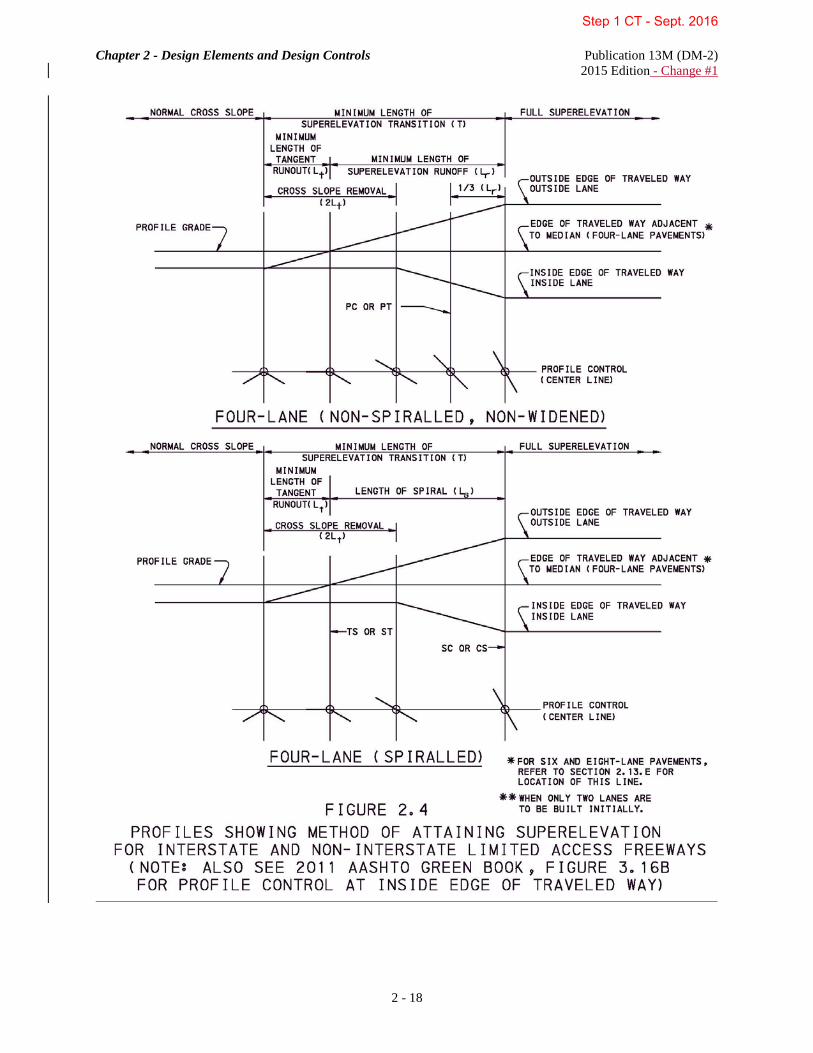
Chapter 2 - Design Elements and Design Controls Publication 13M (DM-2) 2015 Edition - Change #1
2 - 18
Step 1 CT - Sept. 2016

Chapter 2 - Design Elements and Design Controls Publication 13M (DM-2) 2015 Edition - Change #1
2 - 19
Step 1 CT - Sept. 2016

Chapter 2 - Design Elements and Design Controls Publication 13M (DM-2) 2015 Edition - Change #1
2 - 20
Step 1 CT - Sept. 2016

Chapter 2 - Design Elements and Design Controls Publication 13M (DM-2) 2015 Edition - Change #1
2 - 21
Where curves of different radii join, the superelevation transition (T) shall be located entirely within the curve of the larger radius. The difference in the radii of the curves (R) shall be the radius used to determine the length of this transition. For superelevation transitions between reverse curves (i.e., two closely spaced simple curves with deflections in opposite directions), a sufficient length of tangent must be provided. Along this tangent, a normal crown section does not need to be achieved; rather, the roadway may be continuously rotated in a plane about its axis. In this situation, the minimum length of tangent will be that needed to meet the superelevation requirements for the two curves. The minimum length of spiral (Ls) indicated in 16HFigures 2.4 and 17H2.5 may be greater or less than the minimum length of superelevation runoff (Lr) depending on the formula and factors used. The minimum length of superelevation runoff (Lr) is applicable to all superelevated curves and the values for Lr may be used for the minimum lengths of spiral required.
1. Minimum Length of Superelevation Runoff. For appearance and comfort, the length of superelevation runoff should be based on a maximum acceptable difference between the longitudinal grades of the axis of rotation and the edge of traveled way. This relationship is defined as the maximum relative gradient. The axis of rotation is generally represented by the alignment centerline for undivided roadways (see 18HFigure 2.4); however, other pavement reference lines can be used (see 19HFigures 2.5 and 20H2.6). The maximum relative gradient is varied with design speed to provide longer runoff lengths at higher speeds and shorter lengths at lower speeds. The 20042011 AASHTO Green Book, Chapter 3, Exhibit 3-30Table 3-15 provides the values for the maximum relative gradients. Runoff lengths determined on this basis are directly proportional to the total superelevation, which is the product of the lane width and superelevation rate. On the basis of the preceding discussion, the minimum length of superelevation runoff should be determined as:
)(be )(wn
L wd1
r ∆=
where: Lr = minimum length of superelevation runoff (m (ft))
w = width of one traffic lane (typically 3.6 m (12 ft)) n1 = number of lanes rotated ed = design superelevation rate (percent) bw = adjustment factor for number of lanes rotated Δ = maximum relative gradient (percent) This equation can be used directly for undivided streets or highways where the cross section is rotated about the highway centerline and n1 is equal to one-half the number of lanes in the cross section. More generally, this equation can be used for rotation about any pavement reference line provided that the rotated width (wn1) has a common superelevation rate and is rotated as a plane. A strict application of the maximum relative gradient criterion provides runoff lengths for four-lane undivided roadways that are double those for two-lane roadways; those for six-lane undivided roadways would be tripled. While lengths of this order may be considered desirable, it is often not practical to provide such lengths in design. On a purely empirical basis, the minimum superelevation runoff lengths should be adjusted downward to avoid excessive lengths for multilane roadways. The recommended adjustment factors are presented in the 20042011 AASHTO Green Book, Chapter 3, Exhibit 3-31Table 3-16. The adjustment factors listed in the 20042011 AASHTO Green Book, Chapter 3, Exhibit 3-31Table 3-16 are directly applicable to undivided streets and highways. Development of runoff for divided highways is discussed in more detail in the 2011 AASHTO Green Book, Chapter 3, sSection 3.3.8, "Transition Design Controls", "Axis of Rotation with a Median" in the 2004 AASHTO Green Book, Chapter 3. Values for the minimum length of superelevation runoff (Lr) are presented in the 20042011 AASHTO Green Book, Chapter 3, Exhibit 3-32Table 3-17b. The values for the minimum length of superelevation runoff (Lr)
Step 1 CT - Sept. 2016

Chapter 2 - Design Elements and Design Controls Publication 13M (DM-2) 2015 Edition - Change #1
2 - 22
may be increased to provide smoother transitions. If the minimum length of superelevation runoff (Lr) is increased, a revised length of tangent runout (Lt) is required to maintain a smooth edge-of-traveled way profile. The superelevation runoff lengths given in Exhibit 3-32Table 3-17b are based on 3.6 m (12 ft) lanes. For other lane widths, the appropriate runoff length should vary in proportion to the ratio of the actual lane width to 3.6 m (12 ft). Shorter lengths could be applied for designs with 3.0 m (10 ft) and 3.3 m (11 ft) lanes, but considerations of consistency and practicality suggest that the runoff lengths for 3.6 m (12 ft) lanes should be used in all cases. 2. Minimum Length of Tangent Runout. The minimum length of tangent runout is determined by the amount of adverse cross slope to be removed and the rate at which it is removed. To effect a smooth edge of traveled way profile, the rate of removal should equal the relative gradient used to define the superelevation runoff length. Based on this rationale, the following equation should be used to compute the minimum length of tangent runout:
rd
NCt L
ee
L =
where: Lt = minimum length of tangent runout (m (ft))
eNC = normal cross slope rate (percent) ed = design superelevation rate (percent) Lr = minimum length of superelevation runoff (m (ft)) 3. Minimum Length of Superelevation Transition. The minimum length of superelevation transition is determined by the following equation:
T = Lr + Lt
where: T = minimum length of superelevation transition (m (ft)) Lr = minimum length of superelevation runoff (m (ft)) Lt = minimum length of tangent runout (m (ft)) The 20042011 AASHTO Green Book, Chapter 3, Exhibit 3-32Table 3-17b indicates the values to be applied for the minimum length of superelevation runoff (Lr). The values for the minimum length of superelevation runoff (Lr) may be increased to provide smoother transitions. If the minimum length of superelevation runoff (Lr) is increased, a revised length of tangent runout (Lt) is required to maintain a smooth edge-of-traveled way profile. 4. Design Superelevation Tables. The 20042011 AASHTO Green Book, Chapter 3, Exhibits 3-25, 3-26 and 3-27Tables 3-8, 3-9 and 3-10b show minimum values of radius (R) for various combinations of superelevation and design speeds for each of three values of maximum superelevation rate (i.e., for a full range of common design conditions). The maximum superelevation rates are eMax = 4.0% (Exhibit 3-25Table 3-8), eMax = 6.0% (Exhibit 3-26Table 3-9), and eMax = 8.0% (Exhibit 3-27Table 3-10b). Spirals are seldom used when the design superelevation rate is less than 3.0%. When using one of the ExhibitsTables for a given radius, interpolation is not necessary as the superelevation rate should be determined from a radius equal to, or slightly smaller than, the radius provided in the ExhibitTable. The result is a superelevation rate that is rounded up to the nearest 0.2%. Found below are two examples that demonstrate how to obtain the superelevation rate for a given horizontal curve:
Step 1 CT - Sept. 2016

Chapter 2 - Design Elements and Design Controls Publication 13M (DM-2) 2015 Edition - Change #1
2 - 23
a. Example 1 (Metric): Design Speed of Horizontal Curve, Vd = 80 km/h Maximum Superelevation Rate, eMax = 8.0% Radius of Horizontal Curve, R = 436.595 m Solution: From Exhibit 3-27Table 3-10b, e = 6.2% when R = 445 m e = 6.4% when R = 422 m Determine the superelevation rate of the actual horizontal curve from the radius in Exhibit 3-27Table 3-10b that is equal to or slightly smaller. Since 422 m < 436.595 m, specify a design superelevation rate (ed) of 6.4%. Example 1 (English): Design Speed of Horizontal Curve, Vd = 50 mph Maximum Superelevation Rate, eMax = 8.0% Radius of Horizontal Curve, R = 1432.39 ft Solution: From Exhibit 3-27Table 3-10b, e = 6.2% when R = 1480 ft e = 6.4% when R = 1400 ft Determine the superelevation rate of the actual horizontal curve from the radius in Exhibit 3-27Table 3-10b that is equal to or slightly smaller. Since 1400 ft < 1432.39 ft, specify a design superelevation rate (ed) of 6.4%. b. Example 2 (Metric): Design Speed of Horizontal Curve, Vd = 100 km/h Maximum Superelevation Rate, eMax = 6.0% Radius of Horizontal Curve, R = 1164.253 m Solution: From Exhibit 3-26Table 3-9, e = 3.8% when R = 1170 m e = 4.0% when R = 1090 m Determine the superelevation rate of the actual horizontal curve from the radius in Exhibit 3-26Table 3-9 that is equal to or slightly smaller. Since 1090 m < 1164.253 m, specify a design superelevation rate (ed) of 4.0%. Example 2 (English): Design Speed of Horizontal Curve, Vd = 60 mph Maximum Superelevation Rate, eMax = 6.0% Radius of Horizontal Curve, R = 3819.72 ft Solution: From Exhibit 3-26Table 3-9, e = 3.6% when R = 3940 ft e = 3.8% when R = 3650 ft Determine the superelevation rate of the actual horizontal curve from the radius in Exhibit 3-26Table 3-9 that is equal to or slightly smaller. Since 3650 ft < 3819.72 ft, specify a design superelevation rate (ed) of 3.8%.
INTENTIONALLY BLANK
Step 1 CT - Sept. 2016
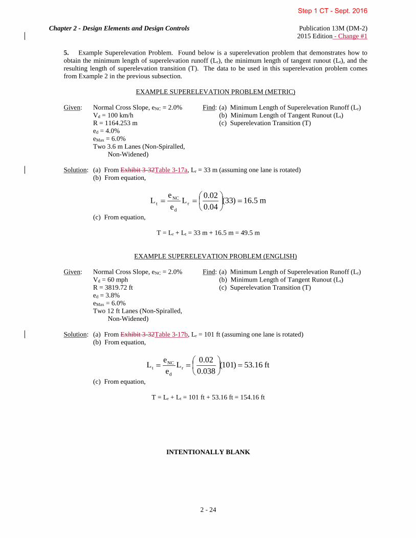
Chapter 2 - Design Elements and Design Controls Publication 13M (DM-2) 2015 Edition - Change #1
2 - 24
5. Example Superelevation Problem. Found below is a superelevation problem that demonstrates how to obtain the minimum length of superelevation runoff (Lr), the minimum length of tangent runout (Lt), and the resulting length of superelevation transition (T). The data to be used in this superelevation problem comes from Example 2 in the previous subsection.
EXAMPLE SUPERELEVATION PROBLEM (METRIC)
Given: Normal Cross Slope, eNC = 2.0% Find: (a) Minimum Length of Superelevation Runoff (Lr) Vd = 100 km/h (b) Minimum Length of Tangent Runout (Lt) R = 1164.253 m (c) Superelevation Transition (T) ed = 4.0% eMax = 6.0% Two 3.6 m Lanes (Non-Spiralled, Non-Widened)
Solution: (a) From Exhibit 3-32Table 3-17a, Lr = 33 m (assuming one lane is rotated) (b) From equation,
m5.16)33(04.002.0L
ee
L rd
NCt =
==
(c) From equation,
T = Lr + Lt = 33 m + 16.5 m = 49.5 m
EXAMPLE SUPERELEVATION PROBLEM (ENGLISH)
Given: Normal Cross Slope, eNC = 2.0% Find: (a) Minimum Length of Superelevation Runoff (Lr) Vd = 60 mph (b) Minimum Length of Tangent Runout (Lt) R = 3819.72 ft (c) Superelevation Transition (T) ed = 3.8% eMax = 6.0% Two 12 ft Lanes (Non-Spiralled, Non-Widened)
Solution: (a) From Exhibit 3-32Table 3-17b, Lr = 101 ft (assuming one lane is rotated) (b) From equation,
ft16.53)101(038.002.0L
eeL r
d
NCt =
==
(c) From equation,
T = Lr + Lt = 101 ft + 53.16 ft = 154.16 ft
INTENTIONALLY BLANK
Step 1 CT - Sept. 2016

Chapter 2 - Design Elements and Design Controls Publication 13M (DM-2) 2015 Edition - Change #1
2 - 25
E. Application of Superelevation.
1. Methods of Attaining Superelevation. On spiral curves, the superelevation shall be applied by removing the adverse cross slope through the minimum length of tangent runout (Lt) distance to the tangent to spiral (TS). Total superelevation shall be attained along the length of spiral and held from the spiral to curve (SC) to the curve to spiral (CS). On non-spiralled, non-widened curves, the superelevation shall be applied by using the method shown in 21HFigure 2.5. Total superelevation shall be reached at a point beyond the point of curvature (PC) at a distance equal to one-third (1/3) of the minimum length of superelevation runoff (Lr). The same procedure shall be followed at the point of tangency (PT). On non-spiralled, widened curves, the superelevation shall be applied by using the method shown in 22HFigure 2.6. Curve widening shall be placed on the inside edge of curve and shall be attained in a distance equivalent to two-thirds (2/3) of the length of superelevation runoff (L) to the nearest 1 m (5 ft). Total superelevation and full extra width shall be reached at a point beyond the point of curvature (PC) at a distance equivalent to one-third (1/3) of the length of superelevation runoff (L). The same procedure shall be followed at the point of tangency (PT). 2. Location of Profile Grade. The profile grade line controls the roadway's vertical alignment through the horizontal curve. Although shown as a horizontal line in 10HFigures 2.4, 11H2.5 and 12H2.6, the profile grade line may correspond to a tangent, a vertical curve, or a combination of the two. In Figure 2.4, the profile grade line corresponds to the centerline profile. In 10HFigures 11H2.5 and 12H2.6, the profile grade line is represented as a "theoretical" centerline profile as it does not coincide with the axis of rotation. For four-lane pavement with paved or unpaved divisor areas, hold profile grade on the edge of traveled way adjacent to the divisor area, as shown in Figure 2.4. See the 20042011 AASHTO Green Book, Exhibit 3-40B Figure 3-16B for profile control at the inside edge of traveled way. For six-lane pavement with paved or unpaved divisors, hold profile grade on the traveled way 3.6 m (12 ft) from the median edges of the traveled way. For eight-lane pavements with paved or unpaved divisors, hold profile grade on the traveled way 7.2 m (24 ft) from the median edges of the traveled way. 3. Additional Design Considerations. In the design of divided highways, the inclusion of a median in the cross section influences the superelevation transition design. This influence stems from the several possible locations for the axis of rotation. The most appropriate location for this axis depends on the width of the median and its cross section. For a discussion of common combinations of these factors and the appropriate corresponding axis location, refer to the 2011 AASHTO Green Book, Chapter 3, sSection 3.3.8, "Transition Design Controls", "Axis of Rotation with a Median" in the 2004 AASHTO Green Book, Chapter 3. For narrow medians less than 6.0 m (20 ft) wide with concrete median barrier, special attention is needed to assure that the centerline elevations are equal elevations along curved roadway sections. Depending on the superelevation and shoulder slopes, it may be necessary to define the profile grade along the high side of the superelevation, At the same location, the low side of the superelevation would be defined as a graphic grade lower than and relative to the high side of the superelevation. For this design situation, the goal would be to install a standard concrete median barrier because it would: (1) provide the same elevations for the gutter lines on either side of the barrier; and (2) be less costly and time consuming than developing a specially-designed and constructed bifurcated concrete median barrier to accommodate differences in elevations on either side of the barrier.
INTENTIONALLY BLANK
Step 1 CT - Sept. 2016
Chapter 2 - Design Elements and Design Controls Publication 13M (DM-2) 2015 Edition - Change #1
2 - 26
Special superelevation design shall be applied in areas involving crossover pavements to prevent flat areas and provide adequate drainage. Narrow medians may present a special problem on superelevated curves. In order to provide required shoulder slopes, it may be necessary to adjust the profile grade lines.
F. Superelevation of City Streets. Local city streets on the highway system are not generally superelevated. In built-up areas, it is desirable to discourage speed and the elimination of superelevation contributes to this objective. Also, established street grades, intersections, curbs, effect on adjacent properties and drainage conditions may inhibit the application of superelevation. There are, however, many occasions when it is desirable to provide superelevation on state highways in urban areas. For example, limited access freeways are superelevated.
G. Superelevation for Curves on Ramps. The 2011 AASHTO Green Book, Chapter 10, sSection 10.9.6, "Ramps", "General Ramp Design Considerations" in the 2004 AASHTO Green Book, Chapter 10 provides guidelines for the design of superelevation and cross-slope on ramps. Guidelines for the development of superelevation at free-flow ramp terminals are found in the 20042011 AASHTO Green Book, Chapter 10, Exhibit 10-58Figure 10-60. 14B2.14 TRAVELED WAY WIDENING ON HORIZONTAL CURVES Vehicles negotiating horizontal curves may require increased traveled way width to make operating conditions on curves comparable to those on tangent sections. The reasons are twofold:
1. The design vehicle occupies a greater width because the rear wheels generally track inside front wheels (offtracking) in negotiating curves.
2. Drivers experience difficulty in steering their vehicles in the center of the lane.
Widening should transition gradually on the approaches to the curve to ensure a reasonably smooth alignment of the edge of the traveled way and to fit the paths of vehicles entering or leaving the curve. The principal points of concern in the design of curve widening which apply to both ends of highway curves are presented below:
1. On simple (unspiralled) curves, widening should be applied on the inside edge of the traveled way only. On curves designed with spirals, widening may be applied on the inside edge or divided equally on either side of the centerline. The final marked centerline, and desirably any central longitudinal joint, should be placed midway between the edges of the widened traveled way.
2. Curve widening should transition gradually over a length sufficient to make the whole of the traveled way fully usable. Preferably, widening should transition over the superelevation runoff length, but shorter lengths are sometimes used. Changes in width normally should be effected over a distance of 30 m to 60 m (100 ft to 200 ft).
3. The edge of the traveled way through the widening transition should be a smooth, graceful curve and a tangent transition edge should be avoided. The transition ends should avoid an angular break at the pavement edge.
4. On highway alignment without spirals, smooth and fitting alignment results from attaining widening with one-half to two-thirds of the transition length along the tangent and the balance along the curve. The inside edge of the traveled way may be designed as a modified spiral, with control points determined by the width/length ratio of a triangular wedge, by calculated values based on a parabolic or cubic curve, or by a larger radius (compound) curve. On highway alignment with spiral curves, the increase in width is usually distributed along the length of the spiral.
Traveled way widening on curves for the main roadway shall be undertaken in accordance with the details in 25HFigure 2.6. Widening is not required under the following conditions:
Step 1 CT - Sept. 2016

Chapter 2 - Design Elements and Design Controls Publication 13M (DM-2) 2015 Edition - Change #1
2 - 27
1. Traveled ways that are 7.2 m (24 ft) wide. 2. Interstate and Other Limited Access Freeways and Arterials. 3. Collectors and Local Roads when the radius is greater than 350 m (degree of curve is less than 5° 00'). Traveled way widening on ramps is discussed in 26HChapter 4, Section 4.7. For additional information concerning traveled way widening on curves, refer to the 2011 AASHTO Green Book, Chapter 3, sSection 3.3.10, "Traveled- Way Widening on Horizontal Curves" in the 2004 AASHTO Green Book, Chapter 3. 15B2.15 TRANSITION (SPIRAL) CURVES AND COMPUTATIONS Transition spirals are curves which provide a gradual change in curvature from a straight to a circular path. Such an alignment is desirable because it permits vehicle operational comfort, gradually introduces superelevation, provides a transitional path to reduce the tendency to deviate from the traffic lane and enhances the appearance of the highway. On Interstate and Non-Interstate Limited Access Freeways, spirals are applicable to curves with radii of 1746.38 m (5729.58 ft) and less (with degree of curves of 1° and greater) and on Arterial roadways, spirals are applicable to curves with radii of 873.19 m (2864.79 ft) and less (with degree of curves of 2° and greater). Superelevation controls spiral lengths, tangent runouts and lengths of superelevation runoff for various radii and are presented in 27HSection 2.13. These are minimum values that may be exceeded. The reference books for spiral curve computations are "Transition Curves for Highways" by Joseph Barnett and "Route Location and Design" by Thomas F. Hickerson, published by the United States Printing Office and McGraw-Hill Book Company, respectively. The minimum data shown for the spiral alignment shall be in accordance with Publication 14M, Design Manual, Part 3, Plans Presentation, Chapter 2. The following example problem illustrates transition (spiral) curve computations using data from Barnett's book (Table II) and the spiral curve formulas contained in 28HFigure 2.7. EXAMPLE PROBLEM (METRIC) Given: PI Sta = 13 + 200.000 Δ = 56° 00' 00" RT Rc = 1000.000 m Ls = 92.000 m Spiral Curve Data: PI Sta = 13 + 200.000 Δ = 56° 00' 00" Δ c = 50° 43' 43.64" Rc = 1000.000 m Lc = 885.384 m θs = 2° 38' 08.18" Ls = 92.000 m Ts = 577.892 m Es = 132.968 m k = 45.996 m p = 0.351 m xc = 91.981 m yc = 1.410 m LT = 61.340 m ST = 30.673 m LC = 91.992 m
EXAMPLE PROBLEM (ENGLISH) Given: PI Sta = 436 + 89.20 Δ = 56° 00' 00" RT Dc = 9° 00' Rc = 636.62' Ls = 300.00' Spiral Curve Data: PI Sta = 436 + 89.20 Δ = 56° 00' 00" Δ c = 29° 00' 00" Dc = 9° 00' 00" Rc = 636.62' Lc = 322.22' θs = 13° 30' 00" Ls = 300.00' Ts = 491.35' Es = 91.06' k = 149.72' p = 5.88' xc = 298.34' yc = 23.47' LT = 200.58' ST = 100.53' LC = 299.26'
Step 1 CT - Sept. 2016

Chapter 2 - Design Elements and Design Controls Publication 13M (DM-2) 2015 Edition - Change #1
2 - 28
Step 1 CT - Sept. 2016

Chapter 2 - Design Elements and Design Controls Publication 13M (DM-2) 2015 Edition - Change #1
2 - 29
EXAMPLE PROBLEM (METRIC): θs = (Ls / 60.96012192) × (1746.378852 / Rc) = (92.000 / 60.96012192) × (1746.378852 / 1000.000) θs = 2° 38' 08.18" p = ("p" constant, Table II) × Ls = 0.00382 × 92.000 p = 0.351 m k = ("k" constant, Table II) × Ls = 0.49996 × 92.000 k = 45.996 m
Ts = k2
tan)pR( c +
∆+
= (1000.000 + 0.351) × tan (28° 00' 00") + 45.996 Ts = 577.892 m Δ c = Δ - 2θs = 56° 00' 00" - 2 × (2° 38' 08.18") Δ c = 50° 43' 43.64" Lc = (30.48006096 × Δ c) / (1746.378852 / Rc) = (30.48006096 × (50° 43' 43.64")) / (1746.378852 / 1000.000) Lc = 885.384 m
1
2cos
12
exsec −∆
=∆
= (1 / cos (28° 00' 00")) - 1 = 0.132570
p)2
exsec)(pR(E cs +∆
+=
= (1000.000 + 0.351)(0.132570) + 0.351 Es = 132.968 m
PI Sta 13+200.000 SC Sta 12+714.108 - Ts -577.892 + Lc +885.384
TS Sta 12+622.108 CS Sta 13+599.492 + Ls +92.000 + Ls +92.000
SC Sta 12+714.108 ST Sta 13+691.492
Step 1 CT - Sept. 2016

Chapter 2 - Design Elements and Design Controls Publication 13M (DM-2) 2015 Edition - Change #1
2 - 30
EXAMPLE PROBLEM (METRIC) (CONTINUED): xc = ("x" constant, Table II) × Ls = 0.99979 × 92.000 xc = 91.981 m yc = ("y" constant, Table II) × Ls = 0.01533 × 92.000 yc = 1.410 m LT = ("LT" constant, Table II) × Ls = 0.66674 × 92.000 LT = 61.340 m ST = ("ST" constant, Table II) × Ls = 0.33340 × 92.000 ST = 30.673 m LC = ("LC" constant, Table II) × Ls = 0.99991 × 92.000 LC = 91.992 m
Suppose a surveyor wanted to locate a point 50.000 m from the TS, measured along the spiral. The intersection angle (θ) between the tangent of the complete curve and the tangent at any other point on the spiral is:
θ = (L2 / Ls
2) × θ s = ((50.000)2 / (92.000)2) × (2° 38' 08.18") θ = 0° 46' 42.51" The values for the tangent distance (x) and tangent offset (y) are: x = ("x" constant, Table II) × L = 0.99998 × 50.000 x = 49.999 m y = ("y" constant, Table II) × L = 0.00453 × 50.000 y = 0.226 m
Step 1 CT - Sept. 2016

Chapter 2 - Design Elements and Design Controls Publication 13M (DM-2) 2015 Edition - Change #1
2 - 31
EXAMPLE PROBLEM (ENGLISH): θ s = (LS / 200) × Dc) = (300 / 200) × 9 θ s = 13° 30' 00" p = ("p" constant, Table II) × LS = 0.01960 × 300 p = 5.88' k = ("k" constant, Table II) × LS = 0.49908 × 300 k = 149.72'
Ts = k2
tan)pR( c +
∆+
= (636.62 + 5.88) × tan (28° 00' 00") + 149.72 Ts = 491.35' Δ c = Δ - 2θs = 56° 00' 00" - (2 × (13° 30' 00")) Δ c = 29° 00' 00" Lc = (Δ c × 100) / Dc = (29.00 × 100) / 9 Lc = 322.22'
1
2cos
12
exsec −∆
=∆
= (1 / cos (28° 00' 00")) - 1 = 0.132570
p)2
exsec)(pR(E cs +∆
+=
= (636.62 + 5.88)(0.132570) + 5.88 Es = 91.06'
PI Sta 436+89.20 SC Sta 434+97.85 - Ts -491.35 + Lc +322.22
TS Sta 431+97.85 CS Sta 438+20.07 + Ls +300.00 + Ls +300.00
SC Sta 434+97.85 ST Sta 441+20.07
Step 1 CT - Sept. 2016

Chapter 2 - Design Elements and Design Controls Publication 13M (DM-2) 2015 Edition - Change #1
2 - 32
EXAMPLE PROBLEM (ENGLISH) (CONTINUED): xc = ("x" constant, Table II) × Ls = 0.99446 × 300 xc = 298.34' yc = ("y" constant, Table II) × Ls = 0.07823 × 300 yc = 23.47' LT = ("LT" constant, Table II) × Ls = 0.66862 × 300 LT = 200.58' ST = ("ST" constant, Table II) × Ls = 0.33511 × 300 ST = 100.53' LC = ("LC" constant, Table II) × Ls = 0.99753 × 300 LC = 299.26'
Suppose a surveyor wanted to locate a point 152.85 ft from the TS, measured along the spiral. The intersection angle (θ) between the tangent of the complete curve and the tangent at any other point on the spiral is:
θ = (L2 / Ls
2) × θ s = ((152.85)2 / (300)2) × (13° 30' 00") θ = 3° 30' 16.09" The values for the tangent distance (x) and tangent offset (y) are: x = ("x" constant, Table II) × L = 0.999605 × 152.85 x = 152.79' y = ("y" constant, Table II) × L = 0.020385 × 152.85 y = 3.12'
INTENTIONALLY BLANK
Step 1 CT - Sept. 2016

Chapter 2 - Design Elements and Design Controls Publication 13M (DM-2) 2015 Edition - Change #1
2 - 33
16B2.16 AIRPORT - HIGHWAY CLEARANCES The Administrator for the Federal Aviation Administration has established specific clearance requirements and criteria for highways and other structures adjacent to airports that are identified in Part 77 of the Federal Aviation Regulations - Federal Aviation Administration. The document is available from the Federal Aviation Administration, Washington, DC or the Superintendent of Documents, US Government Printing Office, Washington, DC and shall be used as a guide in the preparation of the design of highways adjacent or near airports to provide adequate clearance between the highways and the navigable airspace. For additional guidelines on the preparation of data, plans and other pertinent information relative to airport clearance requirements, refer to Publication 10C, Design Manual, Part 1C, Transportation Engineering Procedures, Chapter 4, Section 4.8.F. 17B2.17 SIGHT DISTANCE A. General. For safety on highways,The designer should provide drivers should be provided with sight distance of sufficient length that drivers tocan control the operation of their vehicles to avoid striking an unexpected object in the traveled way. Since the path and speed of these vehicles on highways and streets are subject to the control of drivers whose ability, training and experience are quite varied, proper sight distance shall be provided to enable a vehicle traveling at or near the design speed to stop before reaching a stationary object in its path. Sufficient sight distance should be provided on certain two-lane highways to enable drivers to occupy the opposing traffic lane for passing other vehicles without risk of a crash. Two-lane rural highways should generally provide such passing sight distance at frequent intervals and for substantial portions of their length. Sight distance represents the continuous length ahead along a roadway throughout which an object of specified height is continuously visible to the driver. In design, four sight distances are considered: 1. Passing sight distance. 2. Stopping sight distance. 3. Decision sight distance. 4. Intersection sight distance. B. Criteria for Measuring Sight Distance. The criteria for measuring sight distances are dependent on the height of the driver's eye above the road surface, the specified object height above the road surface and the height and lateral position of sight obstructions within the driver's line of sight:
1. Height of Driver's Eye. For calculating sight distances for passenger vehicles, the height of the driver's eye above the road surface shall be considered as 1.080 m (3.5 ft). For large trucks the driver eye height shall be assumed as 2.330 m (7.6 ft) for design.
2. Height of Object. For stopping sight distance and decision sight distance calculations, the height of object shall be considered as 0.600 m (2.0 ft) above the road surface. For passing sight distance calculations, the height of object shall be considered as 1.080 m (3.5 ft) above the road surface. For intersection sight distance calculations, the height of object shall be considered as 1.080 m (3.5 ft) above the surface of the intersecting road.
3. Sight Obstructions. On a tangent roadway, the obstruction that limits the driver's sight distance is the road surface at some point on a crest vertical curve. On horizontal curves, the obstruction that limits the driver's sight distance may be the road surface at some point on a crest vertical curve, or it may be some physical feature outside of the traveled way, such as a longitudinal barrier, a bridge-approach fill slope, a tree, foliage or the backslope of a cut section. Accordingly, all highway construction plans should be checked in both the vertical and horizontal plane for sight distance obstructions.
C. Passing Sight Distance for Two-Lane Highways. Passing sight distance is the minimum sight distance that shall be available to enable the driver of one vehicle to pass another vehicle safely and comfortably, without interfering with the speed of an oncoming vehicle traveling at the design speed should it come into view after the overtaking maneuver is started. The sight distance available for passing at any place is the longest distance at which a driver whose eyes are 1.080 m (3.5 ft) above the road surface can see the top of an object 1.080 m (3.5 ft) above the road surface.
Step 1 CT - Sept. 2016

Chapter 2 - Design Elements and Design Controls Publication 13M (DM-2) 2015 Edition - Change #1
2 - 34
The available passing sight distance is to abide to Title 75, Vehicle Code § 3305, titled "Limitations on overtaking on the left". It states:
No vehicle shall be driven to the left side of the center or marked center line of the roadway in overtaking and passing another vehicle proceeding in the same direction unless the left side is clearly visible and is free of oncoming traffic for a sufficient distance ahead to permit the overtaking and passing to be completely made without interfering with the operation of any vehicle approaching from the opposite direction or any vehicle overtaken. In every event the overtaking vehicle must return to an authorized lane of travel as soon as practicable and, in the event the passing movement involves the use of a lane authorized for vehicles approaching from the opposite direction, before coming within 200 feet of any approaching vehicle.
Passing sight distance for use in design shouldis to be determined on the basis of the length needed to complete normal passing maneuvers and is determined for a single vehicle passing a single vehicle. When computing minimum passing sight distance on two-lane highways, the following assumptions concerning driver behavior are made: 1. The overtaken vehicle travels at uniform speed. 2. The passing vehicle has reduced speed and trails the overtaken vehicle as it enters a passing section.
3. When the passing section is reached, the passing driver needs a short period of time to perceive the clear passing section and to react to start the maneuver.
4. Passing is accomplished under what may be termed a delayed start and a hurried return in the face of opposing traffic. The passing vehicle accelerates during the maneuver and its average speed during the occupancy of the left lane is 15 km/h (10 mph) higher than that of the overtaken vehicle.
5. When the passing vehicle returns to its lane, there is a suitable clearance length between it and an oncoming vehicle in the other lane.
The minimum passing sight distance for two-lane highways represents the sum of four elements or distances that include:
1. Distance traversed during perception and reaction time and during the initial acceleration to the point of encroachment on the left lane (initial maneuver, d1).
2. Distance traveled while the passing vehicle occupies the left lane (occupation of left lane, d2).
3. Distance between the passing vehicle at the end of its maneuver and the opposing vehicle (clearance length, d3).
4. Distance traversed by an opposing vehicle for two-thirds of the time the passing vehicle occupies the left lane (opposing vehicle, d4 or 2/3 of d2 above).
These distances are diagrammatically illustrated in Exhibit 3-4Figure 2.8 of the 2004 AASHTO Green Book, Chapter 3. For additional information concerning the components used to compute these distances, refer to the section "Passing Sight Distance for Two-Lane Highways" in the 2004 AASHTO Green Book, Chapter 3. Various distances for the components of passing maneuvers are presented for four passing speed groups in Table 2.1. Time and distance values were determined in relation to the average speed of the passing vehicle. The speeds of the overtaken vehicles were approximately 10 mph less than the speeds of the passing vehicles.
Step 1 CT - Sept. 2016

Chapter 2 - Design Elements and Design Controls Publication 13M (DM-2) 2015 Edition - Change #1
2 - 35
FIGURE 2.8 ELEMENTS OF PASSING SIGHT DISTANCE
FOR TWO-LANE HIGHWAYS
TABLE 2.1 ELEMENTS OF PASSING SIGHT DISTANCE
FOR TWO-LANE HIGHWAYS
Component of passing maneuver
Speed range (mph) 30-40 40-50 50-60 60-70
Average passing speed (mph) 34.9 43.8 52.6 62.0
Initial maneuver: a = average accelerationa 1.40 1.43 1.47 1.50 t1 = timea 3.6 s 4.0 s 4.3 s 4.5 s d1 = distance traveled 145 ft 216 ft 289 ft 366 ft
Occupation of left lane: t2 = timea 9.3 s 10.0 s 10.7 s 11.3 s d2 = distance traveled 477 ft 643 ft 827 ft 1030 ft
Clearance length: d3 = distance traveleda 100 ft 180 ft 250 ft 300 ft
Opposing vehicle: d4 = distance traveled 318 ft 429 ft 552 ft 687 ft
Total distance, d1 + d2 + d3 + d4 1040 ft 1468 ft 1918 ft 2383 ft aFor consistent speed relation, observed values adjusted slightly. Note: Acceleration rates are in miles per hour per second (mph/s).
Step 1 CT - Sept. 2016

Chapter 2 - Design Elements and Design Controls Publication 13M (DM-2) 2015 Edition - Change #1
2 - 36
The speed of the passed vehicle has been assumed to be the average running speed at a traffic volume near capacity. The speed of the passing vehicle is assumed to be 10 mph greater. The assumed speeds for passing vehicles in Table 2.2 represent the likely passing speeds on two-lane highways.
TABLE 2.2 PASSING SIGHT DISTANCE FOR
DESIGN OF TWO-LANE HIGHWAYS
DESIGN SPEED (mph)
PASSED VEHICLE
(mph)
PASSING VEHICLE
(mph)
PASSING SIGHT
DISTANCE (ft)
20 18 28 710 25 22 32 900 30 26 36 1090 35 30 40 1280 40 34 44 1470 45 37 47 1625 50 41 51 1835 55 44 54 1985 60 47 57 2135 65 50 60 2285 70 54 64 2480
The values contained in the 2004 AASHTO Green Book, Chapter 3, Exhibit 3-7Table 2.2 represent the design values for minimum passing sight distance. These distances should be exceeded as much as practical and passing sections should be provided as often as can be done at reasonable costs to provide as many passing opportunities as practical. Appreciable grades affect the sight distance needed for passing. The sight distances needed to permit vehicles traveling upgrade to pass safely are greater than those needed on level roads due to reduced acceleration of the passing vehicle and the likelihood that opposing traffic may speed up. Therefore, if passing maneuvers are to be performed on upgrades, passing sight distances should be greater than the derived design values in the 2004 AASHTO Green Book, Chapter 3, Exhibit 3-7Table 2.2. Although no specific adjustments for design are available, the desirability of exceeding the values shown should be recognized. The frequency and length of passing sections encountered on two-lane highways depend on the topography, the design speed, the spacing of intersections and the cost. At each passing section, the length of roadway ahead, with adequate sight distance for passing equal to or greater than the passing sight distance, should be as long as practical. It is not practical to directly indicate the frequency with which passing sections should be provided on two-lane highways due to the physical and cost limitations. Where high traffic volumes are expected on a highway and a high level of service is to be maintained, frequent or nearly continuous passing sight distances should be provided. Passing sight distance is considered only on two-lane roads. At critical locations, a stretch of four-lane construction with stopping sight distance is sometimes more economical than two lanes with passing sight distance. This is particularly practical during stage construction where two lanes of a future four-lane divided highway are being built.
Step 1 CT - Sept. 2016

Chapter 2 - Design Elements and Design Controls Publication 13M (DM-2) 2015 Edition - Change #1
2 - 37
The following is a summary of the design procedure to follow in providing passing sections on two-lane highways:
1. Horizontal and vertical alignment should be designed to provide as much of the highway as practical with passing sight distance (see the 2004 AASHTO Green Book, Chapter 3, Exhibit 3-7Table 2.2).
2. Where the design volume approaches capacity, the effect of lack of passing opportunities in reducing the Level of Service should be recognized.
3. Where the critical length of grade exceeds the physical length of an upgrade, consideration should be given to constructing added climbing lanes. The critical lengths of grade are as shown in the 20042011 AASHTO Green Book, Chapter 3, Exhibits 3-55 and 3-56Figures 3-24 and 3-25.
4. Where the extent and frequency of passing opportunities made available by application of Criteria 1 and 3 are still too few, consideration should be given to the construction of passing lane sections.
D. Stopping Sight Distance. Stopping sight distance represents the length needed for a vehicle traveling at a given speed to stop before reaching an object in its path. Stopping sight distance is measured from the driver's eyes which are 1.080 m (3.5 ft) above the road surface to an object 0.600 m (2.0 ft) above the road surface. Stopping sight distance is the sum of the distance traversed by the vehicle from the instant the driver sights an object necessitating a stop (brake reaction distance) and the distance needed to stop the vehicle from the instant brake application begins (braking distance). The approximate braking distance of a vehicle on a level roadway may be determined from the following equation:
aV075.1d:ENGLISH
aV039.0d:METRIC
22==
where: d = braking distance (m) V = design speed (km/h)
a = deceleration rate (m/s2)
where: d = Bbraking distance (ft) V = Initialdesign speed (mph) a = deceleration rate (ft/s2)
Also, design speed should be used to formulate stopping distance values. The stopping sight distances presented in the 20042011 AASHTO Green Book, Chapter 3, Exhibit 3-1Table 3-1 for the various design speeds are developed based on wet pavement conditions. Stopping sight distances exceeding those shown in the 20042011 AASHTO Green Book, Chapter 3, Exhibit 3-1Table 3-1 should be used as the basis for design wherever practical thereby increasing the margin of safetyfor error for all drivers. The recommended stopping sight distances are based on passenger car operation. Although trucks need longer stopping distances than cars, separate stopping sight distances for both vehicles are not generally used in highway design. Because truck operators are able to see substantially farther beyond vertical sight obstructions because of the higher position of the seat in their vehicles, this factor tends to balance the additional braking lengths for trucks with those for passenger cars. When a highway is on a grade, the equation for braking distance should be modified as follows:
±
=
±
=G
2.32a30
Vd:ENGLISHG
81.9a254
Vd:METRIC22
In this equation, G is the percent of grade divided by 100, and the other terms are as stated previously above in this sSection. The stopping distances needed on upgrades are shorter than on level roadways, and those available on downgrades are longer. The extent of the corrections for grade, which are based on wet pavement conditions, is indicated in the 20042011 AASHTO Green Book, Chapter 3, Exhibit 3-2Table 3-2. On roadways traversed by traffic in both directions, the sight distance available on downgrades is larger than on upgrades, more or less automatically provides the appropriate corrections for grade.
Step 1 CT - Sept. 2016

Chapter 2 - Design Elements and Design Controls Publication 13M (DM-2) 2015 Edition - Change #1
2 - 38
E. Decision Sight Distance. Stopping sight distances are usually sufficient to allow reasonably competent and alert drivers to come to a hurried stop under ordinary circumstances. However, thesegreater distances are often inadequatemay be needed whenwhere drivers must make complex or instantaneous decisions, whenwhere information is difficult to perceive or when unexpected or unusual maneuvers are requiredneeded. Since there are many locations where it would be prudent to provide longer sight distances, decision sight distance provides the greater visibility distance that drivers need. Decision sight distance is the distance needed for a driver to detect an unexpected or otherwise difficult-to-perceive information source or condition in a roadway environment that may be visually cluttered, recognize the condition or its threat potential, select an appropriate speed and path and initiate and complete thecomplex maneuvers safely and efficiently. Decision sight distance offers drivers additional margin for error and affords them sufficient length to maneuver their vehicles at the same or reduced speed rather than to just stop. The following are examples of critical locations where these kinds of errors are likely to occur and where it is desirable to provide decision sight distance: 1. Interchanges and intersections. 2. Locations where unusual or unexpected maneuvers are requiredneeded. 3. Changes in cross section such as toll plazas and lane drops. 4. Areas of concentrated demand where there is apt to be "visual noise". 5. Railroad-highway grade crossings. Decision sight distance criteria that are applicable to most situations have been developed from empirical data. The decision sight distances vary depending on whether the location is on a rural or urban road, and on the type of avoidance maneuver required. If it is not practical to provide these distances because of horizontal or vertical curvatures, special attention should be given to the use of suitable traffic control devices. The 20042011 AASHTO Green Book, Chapter 3, Exhibit 3-3Table 3-3 shows decision sight distance values for various situations rounded for design. For additional information concerning decision sight distance, refer to the 2011 AASHTO Green Book, Chapter 3, sSection 3.2.3, "Decision Sight Distance" in the 2004 AASHTO Green Book, Chapter 3. F. Intersection Sight Distance. Since each intersection has the potential for several different types of vehicle conflicts, those conflicts can be greatly reduced through provisions for proper sight distances and appropriate traffic controls. The driver of a vehicle approaching an intersection should have an unobstructed view of the entire intersection, including any traffic control devices, and sufficient lengths along the intersecting highway to permit the driver to anticipate and avoid potential collisions. For procedures to determine sight distances at intersections according to different types of traffic control, refer to the 2011 AASHTO Green Book, Chapter 9, sSection 9.5, "Intersection Sight Distance" in the 2004 AASHTO Green Book, Chapter 9. These types include: 1. Case A - Intersections with No Control. 2. Case B - Intersections with Stop Control on the Minor Road a. Case B1 - Left Turn from the Minor Road b. Case B2 - Right Turn from the Minor Road c. Case B3 - Crossing Maneuver from the Minor Road 3. Case C - Intersections with Yield Control on the Minor Road a. Case C1 - Crossing Maneuver from the Minor Road b. Case C2 - Left or Right Turn from the Minor Road 4. Case D - Intersections with Traffic Signal Control 5. Case E - Intersections with All-Way Stop Control 6. Case F - Left Turns from the Major Road Sight distance between intersecting traffic flows is not considered a requirement for intersections controlled by traffic signals, since the flows move at separate times. However, due to a variety of operational characteristics, such as violation of signal, right turn on red, malfunction of the signal etc., sight distance should be provided for
Step 1 CT - Sept. 2016

Chapter 2 - Design Elements and Design Controls Publication 13M (DM-2) 2015 Edition - Change #1
2 - 39
signalized intersections as well. A basic requirement for all controlled intersections is that drivers must be able to see the control device soon enough to perform the action it indicates. For additional information concerning sight distance for intersections, refer to the 2011 AASHTO Green Book, Chapter 9, sSection 9.5, "Intersection Sight Distance" in the 2004 AASHTO Green Book, Chapter 9. G. Sight Distance for Multilane Highways. It is not necessary to consider passing sight distance on highways or streets that have two or more traffic lanes in each direction of travel. Passing maneuvers on multilane roadways are expected to occur within the limits of the traveled way for each direction of travel. Thus, passing maneuvers that involve crossing the centerline of four-lane undivided roadways or crossing the median of four-lane roadways should be prohibited. Multilane roadways should have continuously adequate stopping sight distance with greater-than-design sight distances preferred. For additional information regarding sight distance for multilane highways, refer to the 2011 AASHTO Green Book, Chapter 3, Section 3.2.5, "Sight Distance for Multilane Highways". H. Sight Distance on Horizontal Curves. The sight distance needed across the inside of horizontal curves, where there are sight obstructions such as walls, cut slopes, buildings and possibly guide rail or median barrier, may need adjustment in the normal highway cross section or a change in the alignment if removal of the obstruction is impractical to provide adequate sight distance. Because of the many variables in alignment, in cross section and in the number, type and location of potential obstructions, specific study is usually needed for each individual curve. With sight distance for the design speed as a control, check the actual conditions on each curve and make the appropriate adjustments to provide adequate sight distance. For general use in design of a horizontal curve, the sight line is a chord of the curve, and the stopping sight distance is measured along the centerline of the inside lane around the curve. The 20042011 AASHTO Green Book, Chapter 3, Exhibit 3-53Figure 3-22b indicates the horizontal sight line offsets for needed clear sight areas that satisfy stopping sight distance criteria presented in the 20042011 AASHTO Green Book, Chapter 3, Exhibit 3-1Table 3-1. The horizontal sight line offset values in the 20042011 AASHTO Green Book, Chapter 3, Exhibit 3-53Figure 3-22b are derived from geometry for the several dimensions, as indicated in the diagrammatic sketch in the 20042011 AASHTO Green Book, Chapter 3, Exhibit 3-54Figure 3-22b and in the 20042011 AASHTO Green Book, Chapter 3, Equation 3-383-36. Using the height criteria for stopping sight distance of 1.080 m (3.5 ft) for height of eye and 0.600 m (2.0 ft) for height of object, a height of 0.840 m (2.75 ft) may be used as the midpoint of the sight line where the cut slope usually obstructs sight. This assumes there is little or no vertical curvature. The method presented in the 20042011 AASHTO Green Book, Chapter 3, Exhibits 3-53 and 3-54Figures 3-22b and 3-23 is only exact when both the vehicle and the sight obstruction are located within the limits of the simple horizontal curve. When either the vehicle or the sight obstruction is located beyond the limits of the simple curve, the values obtained are only approximate. The same is true if either the vehicle, or the sight obstruction, or both is located within the limits of a spiral or a compound curve. In these instances, the value obtained would result in horizontal sight line offset values slightly larger than those needed to satisfy the desired stopping sight distance. The minimum passing sight distance for a two-lane road or street is about four times as great as the minimum stopping sight distance at the same design speed. The equation indicatedmethodology described in the 2004 AASHTO Green Book, Chapter 3 (Equation 3-38) Section 2.17.C is directly applicable for passing sight distance confined to tangent and very flat alignment conditions and are of limited practical value except on long curves since it is difficult to maintain passing sight distance on other than very flat curves. For additional information regarding sight distance on horizontal curves, refer to the 2011 AASHTO Green Book, Chapter 3, Section 3.3.12, "Sight Distance on Horizontal Curves".
Step 1 CT - Sept. 2016

Chapter 2 - Design Elements and Design Controls Publication 13M (DM-2) 2015 Edition - Change #1
2 - 40
18B2.18 OTHER ELEMENTS AFFECTING GEOMETRIC DESIGN In addition to the design elements presented in previous Sections, there are other elements that affect or are affected by the geometric design of a roadway. Each of these additional elements is addressed briefly below only to the extent necessary to indicate its relationship to geometric design. A. Traffic Control Devices. Traffic control devices provide guidance and navigation information and also display additional information that augments some roadway or environmental feature that might otherwise be overlooked or difficult to receive. Traffic control devices include regulatory, warning, route guidance information, markings and delineation measures. Control devices are essential elements for all functional classification systems and their application shall be consistent and uniform especially at intersections where multiphase or actuated traffic signals may be needed. Geometric design should not be considered complete nor should it be implemented until it has been determined that needed traffic control devices will have the desired effect in controlling traffic. Traffic control signals (including railroad crossing signals) represent devices that control vehicular and pedestrian traffic by assigning the right-of-way to various movements for certain pretimed or traffic-actuated intervals of time. Since they are one of the key elements in the function of many urban streets and rural intersections, the planned signal operation for each intersection of a facility should be integrated with the design so as to achieve optimum operational efficiency. The guidelines for the design and operation of traffic signals on all streets and highways shall conform to Publication 149, Traffic Signal Design Handbook; Publication 408, Specifications; Publication 111M, Traffic Control - Pavement Marking and Signing Standards, TC-8600 and TC-8700 Series; and Publication 148, Traffic Standards - Signals, TC-7800 Series. For railroad crossing signals, refer to the MUTCD, Part 8. Signing and markingTraffic signs, pavement markings, and traffic signals are directly related to the design of the highway or street and are features of traffic control and operation that should be considered in the geometric layout of such a facility. The signing and markingTraffic control devices should be designed concurrently with the geometrics since future operational problemsefficiency can be reduced significantly enhanced if bothsigns, markings, and signals are treated as an integral part of design. The extent to which signs and markingstraffic control devices are used depends on the traffic volume, the type of facility, and the extent of traffic control appropriate for safe and efficient operation. Although safety and efficiency of operation depend to a considerable degree on tThe geometric design of the facility, the physical layout should also be supplemented by effective signing, markings, and signals as a means of informing, warning and controlling drivers during day and night operations and under a variety of environmental conditions. Signing, marking, and signal plans should be coordinated with horizontal and vertical alignment, sight distance obstructions, operational speeds and maneuvers and other applicable items should be worked out before completion of design. Markings and markers, like signs, have the function of controlling traffic to encourage safe and efficient operation. Markings or markers either supplement regulatory or warning signs or serve independently to indicate certain regulations or warn of certain conditions present on the highway. The design, location and operation of all traffic signs and markings shall be governed by the regulations contained in 67 PA Code § 212. Physical obstructions in or near the roadway should be removed in order to provide the appropriate clear zone. Where removal is impractical, such objects should be adequately marked by painting or by use of other high-visibility material. Where the object is in the direct line of traffic, the obstruction and marking thereon preferably should be illuminated at night by floodlighting; where this is not practical, the markings should be effectively reflectorized. B. Intelligent Transportation Systems. Intelligent Transportation Systems (ITS) involve the installation and use of electronic message signs, highway advisory radios, closed circuit television (CCTV) and other electronic devices by PennDOT to provide real-time emergency or congestion information to motorists. Design guidance is found in Publication 646, Intelligent Transportation Systems Design Guide and Publication 647M, Civil and Structural Standards for Intelligent Transportation Systems. Maintenance guidance is provided in Publication 697, Intelligent Transportation Systems Maintenance Standards. C. Erosion Control. Erosion prevention represents one of the major factors in design, construction and maintenance. The most direct application of erosion control occurs in drainage design and in the writing of
Step 1 CT - Sept. 2016

Chapter 2 - Design Elements and Design Controls Publication 13M (DM-2) 2015 Edition - Change #1
2 - 41
specifications of landscaping and slope planting. Erosion and maintenance are minimized largely by: (1) the use of flat side slopes, rounded and blended with natural terrain; (2) serrated cut slopes; (3) drainage channels designed with due regard to width, depth, slopes, alignment and protective treatment; (4) inlets located and spaced with erosion control in mind; (5) prevention of erosion at culvert outlets; (6) proper facilities for groundwater interception; (7) dikes, berms and other protective devices; (8) sedimentation devices to trap sediment at strategic locations; and (9) protective ground covers and planting. The procedures and criteria for effecting maximum erosion and sediment control shall follow the guidelines contained in Chapter 13 and shall be constructed in accordance with Publication 72M, Roadway Construction Standards and Publication 408, Specifications, for all functional classification systems. D. Landscape Development. Landscape development should be provided for aesthetic and erosion control purposes in keeping with the character of the highway and its environment. Programs include the following general areas of improvement: (1) preservation of existing vegetation; (2) transplanting of existing vegetation where practical; (3) planting of new vegetation; (4) selective clearing and thinning; and (5) regeneration of natural plant species and material. The objectives in planting or the retention and preservation of natural growth on roadsides are closely related. In essence, they are to provide vegetation that: (1) vegetation that shallwill be an aid to aesthetics and safety; (2) vegetation that shallwill aid in lowering construction and maintenance costs; and (3) vegetation that creates interest, usefulness and beauty for the pleasure and satisfaction of the traveling public. Care should be exercised to ensure that guidelines for sight distances and clearance to obstructions are observed especially at intersections. Landscaping should also consider maintenance problems and cost, future sidewalks, utilities, additional lanes and possible bicycle facilities. All landscape development shall conform to the general principles established in 29HChapter 8 and the additional sources of reference listed therein for all functional classification systems. E. Railroad-Highway Grade Crossings. All railroad-highway grade crossings come under the jurisdiction of the Public Utility Commission (PUC) and cannot be constructed or altered without their prior approval. Appropriate grade crossing warning devices, as determined by the PUC, shall be installed at all railroad-highway grade crossings. Details of the available devices to be used are given in Publication 212, Official Traffic Control Devices and in the MUTCD, Part 8. Sight distance is an important consideration at railroad-highway grade crossings. There shall be sufficient sight distance on the highway for the driver to recognize the crossing, perceive the warning device and stop if necessary. Another important consideration is the required minimum railroad vertical and/or horizontal clearances between the track and an obstruction. Refer to Publication 371, Grade Crossing Manual, Appendix H for these requirements. Additional design guidance for railroad requirements may be found in Publication 371, Grade Crossing Manual. F. Drainage. Highway drainage facilities carry water across the right-of-way and remove storm water from the roadway itself. Drainage facilities include bridges, culverts, channels, curbs, gutters and various types of drains. Hydraulic design procedures, requirements for stream crossing and floodplain encroachments, hydraulic capacities and locations of the above structures should be designed to take into consideration damage to upstream property and reduce traffic interruption by flooding as is consistent with the importance of the roadway, the design traffic service requirements and available funds. The design and criteria for highway drainage facilities shall conform to the guidelines presented in Chapter 10 and shall be constructed in accordance with Publication 72M, Roadway Construction Standards; Publication 408, Specifications; and other applicable Department directives. Additional design guidance may be found in Publication 584, PennDOT Drainage Manual. G. Lighting. Lighting may improve the safety of areduce nighttime crashes on a highway or street and improve the ease and comfort of operation thereon. Lighting of rural highways may be desirable, but the need for such fixed-source lighting is much less than on streets and highways in urban areas. Lighting of rural highways is seldom justified except in certain critical areas such as interchanges, intersections, railroad-highway grade crossings, long or narrow bridges, tunnels, sharp curves and other areas where roadside interferences are present. Since highway lighting for freeways is intimately associated with the type and location of highway signs, full effectiveness should include the joint design of these two areas. The design criteria and policies for highway lighting systems shall
Step 1 CT - Sept. 2016

Chapter 2 - Design Elements and Design Controls Publication 13M (DM-2) 2015 Edition - Change #1
2 - 42
conform to the procedures presented in 30HChapter 5 and the additional sources of reference listed therein and shall be constructed in accordance with Publication 72M, Roadway Construction Standards and Publication 408, Specifications. H. Safety Rest Areas, Welcome Centers and Scenic Overlooks. These areas represent functional and desirable elements of the complete highway facility and are provided for the safety and convenience of highway users. Site selection for safety rest areas, welcome centers and scenic overlooks should consider the scenic quality of the area, accessibility and adaptability to development that includes facilities designed to accommodate the needs of older persons and persons with disabilities. The design procedures associated with these facilities shall be in accordance with the criteria presented in 31HChapter 9 and the additional sources of reference listed therein. I. Utilities. Highway and street improvements, whether upgraded within the existing right-of-way or entirely on new right-of-way, must be designed to avoid or minimize impacts to utility facilities. This is in accordance with State and Federal regulations (PA One Call, 23 CFR and the Federal Program Guide on Utility Relocation and Accommodation on Federal-Aid Highway Projects) and must be done. The existing utilities should be placed on the plans early in the development of a project to identify conflicts when designing the new or upgraded highway and street improvements. The use of Subsurface Utility Engineering (SUE) may be required to determine the exact horizontal and vertical location of all underground utilities (refer to Publication 16, Design Manual, Part 5, Utility Relocation, Chapter 6, Subsurface Utility Engineering). The SUE Utility Impact Form (see Publication 16, Design Manual, Part 5, Utility Relocation, Appendix A-501) is a tool that was developed to address the legal requirements and to comply with the State and Federal laws. The form provides an analysis based on project criteria to determine if SUE use is "practicable," when SUE should be considered on a project, and what SUE quality levels should be utilized. SUE should be considered for all projects regardless of a project's estimated cost. The SUE Impact form should be completed by the Project Manager in coordination with the District Utility Relocation Unit. Special construction items should be shown on the utility submissions (see Publication 16, Design Manual, Part 5, Utility Relocation, Appendix A-502). It is important that the Project Manager coordinate plan revisions with the District Utility Administrator to determine the effect they may have on the relocation of utilities. In many cases minor revisions to the highway plan can have major impacts to the relocation of utilities. Although utilities generally have little effect on the geometric design of the highway or street, full consideration should be given to measures, reflecting sound engineering principles and economic factors, needed to preserve and protect the integrity and visual quality of the highway or street, its maintenance efficiency and the safety of traffic. The various policies and procedures to accomplish utility adjustments made necessary by highway construction projects are contained in Publication 16, Design Manual, Part 5, Utility Relocation. J. Bicycle Facilities. The bicycle has become an element for consideration in the highway design process. Most of the distance required for bicycle travel is comprised of the current street and highway system. However, at certain locations or in certain corridors, a designated bikeway (for either exclusive or nonexclusive bicycle use) may be provided to supplement the existing street or highway system. The design of bikeway facilities shall adhere to the guidelines presented in 32HChapter 16 and 33HChapter 19. K. Noise Control and NoiseSound Barriers. Since motor vehicles generate traffic noise, the design of highways may require the establishment of measures to minimize the radiation of noise into noise-sensitive areas by evaluating existing or potential noise levels and estimate the effectiveness of reducing highway traffic noise through location and design considerations. The actual noise level is not, in itself, a good predictor of annoyance since human reactions to noise are usually less if the noise source is hidden from view. The type of development in a particular area can affect the annoyance level since high traffic noise levels are usually more tolerable in industrial than in residential areas. Other factors that influence human reactions to noise are pitch and intermittency because the higher the pitch or the more pronounced the intermittency of the noise, the greater the degree of annoyance. To combat the adverse effect noise can have on people living on, working on or otherwise using land adjacent to highways, noisesound barriers may be constructed on both new and existing highways. Careful consideration shall
Step 1 CT - Sept. 2016

Chapter 2 - Design Elements and Design Controls Publication 13M (DM-2) 2015 Edition - Change #1
2 - 43
be exercised to ensure the location and construction of noisesound barriers shallwill not compromiseincrease the safetyseverity of crashes that may occur the highway by providingand will provide proper horizontal clearanceslateral offsets and adequate sight distances, particularly where the location of the noisesound barrier is along the inside of a curve. An effective method of reducing traffic noise from adjacent areas is to design the highway so that some form of solid material, such as earth or concrete, blocks the line of sight between the noise source and the receptors. Buffer plantings, such as shrubs, trees or ground covers, offer some noise reduction while exceptionally wide and dense plantings may result in substantial reductions in noise levels. In terms of noise considerations, a depressed highway section is the most desirable noise reduction design. For additional information and general considerations for noisesound barriers including design procedures, noise reduction designs and the assessment of noise impacts on highway projects, refer to Publication 10C, Design Manual, Part 1C, Transportation Engineering Procedures, Chapter 4, Section 4.9.G.12 and the 2011 AASHTO Green Book, Chapter 4, sSection 4.14, "Noise Control" in the 2004 AASHTO Green Book, Chapter 4. L. Structures. The established standard policies, procedures and specifications for the design and construction of highway structures shall be governed by Publication 15M, Design Manual, Part 4, Structures and the additional sources of reference listed therein. M. Pedestrian Facilities. Since pedestrians represent a part of every roadway environment, attention should be paid to their presence in rural as well as in urban areas. The urban pedestrian, being more prevalent, influences roadway design features more often than the rural pedestrian does. Pedestrian facilities may include sidewalks, crosswalks, traffic control features and curb ramps for persons with disabilities. When designing urban highways with substantial pedestrian-vehicle conflicts, tThe following are some measures that could be considered tomay help reduce thesepedestrian-vehicle conflicts and may increase the efficientimprove operations of the roadwayon urban highways: (1) eliminate left and/or right turns; (2) prohibit free-flow right-turn movements; (3) prohibit right turn on red; (4) convert from two-way to one-way street operation; (5) provide separate signal phases for pedestrians; (6) eliminate selected crosswalks; and (7) provide for pedestrian grade separations. Pedestrian accommodation and pedestrian facilities shall follow the design criteria and guidelines presented in 34HChapter 6. For additional information concerning general considerations, physical characteristics of pedestrians and characteristics of pedestrians with disabilities, refer to the 2011 AASHTO Green Book, Chapter 2, sSection 2.6, "The Pedestrian" in the 2004 AASHTO Green Book, Chapter 2 and 35HChapter 19. N. Highway Capacity Analysis. The term "capacity" is used to express the maximum number of vehicles that have a reasonable expectation of passing over a given section of a lane or a roadway during a given time period under prevailing roadway and traffic conditions. The principles and major factors concerning highway design capacity analysis are presented in the HCM. O. Mass Transit Facilities. Wherever there is a demand for highways to serve automobile traffic, there is likewise a demand for public transportation. The requirements for public transit and their compatibility with other highway traffic shall be considered in the development and design of highways to insure the forms of interference between the two are minimized through careful planning, design and traffic control measures. Mass transit facilities may include bus stops and bus turnouts, park and ride facilities, rail transit and high-occupancy vehicle (HOV) facilities. For additional information concerning the location and design of these mass transit facilities, refer to the 2011 AASHTO Green Book, Chapter 4, sSections 4.19, "Bus Turnouts", Section 7.3.18, "Public Transit Facilities", and Section 8.4.8, "Accommodation of TransitManaged Lanes and High-Occupancy VehicleTransit Facilities" in the 2004 AASHTO Green Book, Chapters 4, 7, and 8, respectively and 36HChapter 19. P. Special Purpose Roads. For the purpose of design, highways are classified by function with specific design criteria given for each functional classification (see 37HChapter 1, Section 1.2). However, certain roads do not fit into any of the current functional classifications due to their purpose and are referred to as special purpose roads. These roads include: (1) recreational roads; (2) resource recovery roads; and (3) local service roads and, because of their uniqueness, separate design criteria are provided as presented in the 2011 AASHTO Green Book, Chapter 5, sSection 5.4, "Special-Purpose Roads" in the 2004 AASHTO Green Book, Chapter 5. Recreation roads, as the name implies, serve recreation sites and areas through the use of primary access roads, circulation roads and area roads. Resource recovery roads include mining and logging roads that are primarily composed of large, slow-moving, heavily loaded vehicles. Local service roads represent roads serving isolated areas that have little or no potential for further development with traffic that is very low and generally consists of drivers who are familiar with the road.
Step 1 CT - Sept. 2016

Chapter 2 - Design Elements and Design Controls Publication 13M (DM-2) 2015 Edition - Change #1
2 - 44
Although not classified as special purpose roads, frontage roads, cul-de-sacs, turnarounds and alleys are presented herein since their functions apply to special areas of accessibility. Frontage roads serve numerous functions depending on the type of roadway they serve and the character of the surrounding area. Frontage roads can be used on all types of highways to: (1) control access to an arterial; (2) function as a street facility serving adjoining properties; (3) maintain circulation of traffic on each side of an arterial; (4) segregate local traffic from higher-speed, through traffic; and (5) intercept driveways of residences and commercial establishments along the highway. For information on data and features of frontage roads, refer to the 2011 AASHTO Green Book, Chapter 4, sSection 4.12, "Frontage Roads" in the 2004 AASHTO Green Book, Chapter 4. Cul-de-sacs and turnarounds are normally employed for use on a local street system that is open at one end. A special turning area at the closed end is used to enable passenger vehicles and local delivery trucks to U-turn or at least turn around by backing once. Alleys are also associated with local street systems. They provide access to the side or rear individual land parcels with connections to streets or to other alleys. The geometric features and design guidelines for cul-de-sacs, turnarounds and alleys are presented in the 2011 AASHTO Green Book, Chapter 5, sSections 5.3.2, "Cross-Sectional Elements", "Cul-de-Sacs and Turnarounds" and "Alleys" in the 20042011 AASHTO Green Book, Chapter 5. Q. Traffic Barriers. Traffic barriers are used to prevent vehicles that leave the traveled way from hitting ancolliding with objects that hashave greater crash severity potential than the barrier itself. Because barriers are themselves a source of crash potential themselves, their use should be carefully considered. The criteria and guidelines for the design, placement and installation of longitudinal barrier systems (roadside barriers and median barriers) and impact attenuators are presented in 38HChapter 12. R. Curbs and Driveways. The type and location of curbs affects driver behavior and, in turn, the safety and utility of a highway. Curbs serve any or all of the following purposes: (1) drainage control; (2) roadway edge delineation; (3) right-of-way reduction; (4) aesthetics; (5) delineation of pedestrian walkways; (6) reduction of maintenance operations; and (7) assistance in orderly roadside development. Curb configurations include both vertical and sloping curves. The design and construction of curbs shall be in accordance with Publication 72M, Roadway Construction Standards; Publication 408, Specifications; and 39HChapters 6, 40H7, and 41H9. For further information refer to the 2011 AASHTO Green Book, Chapter 4, sSections 4.7, "Curbs" and Section 4.15.2, "Driveways" in the 2004 AASHTO Green Book, Chapter 4. Vertical curbs should not be used along freeways or other high-speed roadways because an out-of-control vehicle may overturn or become airborne as a result of an impact with such a curb. Since curbs are not adequate to prevent a vehicle from leaving the roadway, a suitable traffic barrier should be provided where redirection of vehicles is needed. Sloping curbs can be used at median edges, to outline channelizing islands in intersection areas or at the outer edge of the shoulder. Sloping curbs are designed so vehicles can cross them readily when the need arises. S. Maintenance of Traffic Through Construction Areas. Maintaining a safe flowMaintenance of traffic during construction shall be carefully planned in the development of construction plans, and the designs for traffic control shall minimize the effect on traffic operations by minimizing the frequency or duration of interference with normal traffic flow. The development of traffic control plans is an essential part of the overall project design and depends on the nature and scope of the improvement, volumes of traffic, highway or street pattern and capacities of available highways or streets. A well-thought-out and carefully developed traffic control plan through a construction work zone can contribute significantly to the safe and efficient flow of traffic as well as the safety ofreduced potential for injury to the construction forces. The goal of any traffic control plan should be to safely routeeffectively guide traffic at a controlled speed through or around construction areas with geometrics and traffic control devices as nearly comparablesimilar as practical to those utilized for normal operating situations as practical while providing room for construction operations. The maintenance of traffic through construction areas shall adhere to the guidelines presented in Publication 212, Official Traffic Control Devices and Publication 213, Temporary Traffic Control Guidelines. T. Outer Separations and Border Areas. The area between the traveled way of a roadway for through traffic and a frontage road (see Section O above) or a street for local traffic is referred to as the outer separation. These function as buffers for noise abatement in sensitive areas and provide space for shoulders, sideslopes, drainage, access-control fencing and possibly retaining walls and ramps in urban areas. The outer separation should be as wide as economically possible so local traffic will have less influence on through traffic and should lend itself to landscape treatment that can enhance the appearance of both the highway and adjoining property. Where ramp connections are provided between the through roadway and the frontage road, the outer separation should be wider than normal with the needed width dependent on the design requirements of the ramp termini. Where two-way
Step 1 CT - Sept. 2016

Chapter 2 - Design Elements and Design Controls Publication 13M (DM-2) 2015 Edition - Change #1
2 - 45
frontage roads are provided, desirably the outer separation should be sufficiently wide to minimize the effects of the approaching traffic particularly the nuisance of headlight glare at night. The cross section and treatment of an outer separation depends largely upon its width and the type of arterial and frontage road. Preferably, the strip should drain away from the through roadway either to a curb and gutter at the frontage road or to a swale within the strip. Typical cross sections for outer separations are presented in the 20042011 AASHTO Green Book, Chapter 4, Exhibit 4-13Figure 4-11. Where there are no frontage roads or local streets functioning as frontage roads, the area between the traveled way of the main lanes and the right-of-way line is referred to as the border area. The border area between the roadway and the right-of-way line should be wide enough to serve several purposes, including provision ofserving as a buffer space between pedestrians and vehicular traffic, sidewalk space, snow storage, an area for placement of underground and above ground utilities such as traffic signals, parking meters and fire hydrants and an area for maintainable aesthetic features such as grass or other landscaping features. The border width should be 2.4 m (8 ft) wide and preferably 3.6 m (12 ft) wide or more. Every effort should be made to provide wide borders not only to serve functional needs but also as a matter of aesthetics, safetyreducing crash frequencies and reducing the nuisance of traffic to adjacent development. U. Median Crossovers. Consideration shall be given to providing openings in medians on Interstate and other Limited Access Freeways for use by emergency and other authorized vehicles. Median crossovers are also intended to be used where operation of snow and ice removal equipment to clear interchange ramps would be expedited. The need for such openings shall be determined by the District Executive and their use shall conform to the guidelines presented below. Median barrier and end treatments, if required at these locations, shall be constructed as indicated on the Standard Drawings. Crossovers should never be provided unless justified. Median crossovers constructed on Interstate Highways shall be approved by the Federal Highway Administration (FHWA). A submission shall be made to the Central Office, Bureau of Project Delivery, Highway Delivery Division, Highway Design and Technology Section for this purpose. Median crossovers can be used on Interstate and Non-Interstate Limited Access Freeways when the median width is greater than 10 m (33 ft). If crossovers are required in a median where the width is not greater than 10 m (33 ft), coordination with the Central Office, Bureau of Project Delivery, Highway Delivery Division, Highway Design and Technology Section is required. Median crossovers can be located as follows:
1. Where the distance between the ends of speed-change tapers for adjacent interchanges is less than 6 km (4 mi), one median crossover may be provided. This crossover should be constructed at a suitable location midway between the interchanges, but not closer than 450 m (1,500 ft) from the end of any speed-change taper or structure. Crossovers should be located only where above-minimum stopping sight distance is provided and preferably should not be located on superelevated curves.
2. Where the distance between the ends of speed-change tapers for adjacent interchanges is greater than 6 km (4 mi), two or more median crossovers may be provided. These crossovers shall be provided at no less than 5 km (3 mi) intervals, and shall not be constructed closer than 450 m (1,500 ft) from the end of any speed-change taper or structure. 3. One set of dual crossovers may be located at or near a State or County line if the proximity of the nearest interchange or median crossover is greater than 1.6 km (1 mi). The intent of the dual crossovers is to allow for the safe operation of winter maintenance activities, eliminating the need for winter maintenance vehicles to back up to a crossover after plowing or spreading materials beyond the crossover. If an acceptable location for dual crossovers cannot be established at the State or County line, the pair may be shifted to the nearest acceptable location that has adequate sight distance. If dual crossovers are required, coordination with the Central Office, Bureau of Project Delivery, Highway Delivery Division, Highway Design and Technology Section is required.
All median crossovers shall conform to the typical detail shown in 42HFigure 2.82.9. They shall be constructed with a paved surface, paved shoulders, and deceleration lanes as shown. A typical detail for dual crossovers at or near a State or County line is shown in 43HFigure 2.92.10.
Step 1 CT - Sept. 2016

Chapter 2 - Design Elements and Design Controls Publication 13M (DM-2) 2015 Edition - Change #1
2 - 46
The location of median crossovers should be coordinated with proposed or existing median drainage systems to eliminate exposed pipe end sections that could present an obstacle to errant vehicles. Where cross pipes are deemed necessary, careful thought should be given to providing a safe, hydraulically-efficient drainage system that uses proper drainage appurtenances to eliminate undesirable conditions. The kind, size, and location of the drainage system required is dependent on actual field conditions. All exposed culvert end sections shall be designed to ensure they can be safely negotiated by errant vehicles. The ends of the pipe should be sloped to match the side slopes of the crossover. All pipe openings greater than 450 mm (18 in) in diameter should be designed to provide safe traversability by using a grate, longitudinal or transverse bars or a combination thereof. Embankment slopes in the crossover area should be 1V:6H minimum, longitudinally and 1V:12H minimum, transversely (1V:20H desirable), with respect to the crossover pavement. In order to limit usage to emergency and other authorized vehicles, appropriate signing and delineation shall be used (see Traffic Standard TC-8604). When eliminating existing crossovers, proper coordination should be conducted with local emergency management officials to ensure their operations are not significantly impacted.
Step 1 CT - Sept. 2016

Chapter 2 - Design Elements and Design Controls Publication 13M (DM-2) 2015 Edition - Change #1
2 - 47
Step 1 CT - Sept. 2016

Chapter 2 - Design Elements and Design Controls Publication 13M (DM-2) 2015 Edition - Change #1
2 - 48
Step 1 CT - Sept. 2016

Chapter 2 - Design Elements and Design Controls Publication 13M (DM-2) 2015 Edition - Change #1
2 - 49
Step 1 CT - Sept. 2016

Chapter 2 - Design Elements and Design Controls Publication 13M (DM-2) 2015 Edition - Change #1
2 - 50
19B2.19 DESIGN CONTROLS This section presents the characteristics of design vehicles, driver performance and traffic data that are necessary for the optimization or improvement in the design of the various highways that comprise the functional classification system. Additional sources of information and criteria to supplement the general characteristics presented are contained in the 20042011 AASHTO Green Book, Chapter 2, "Design Controls and Criteria". A. Design Vehicles. Design vehicles represent selected motor vehicles with the weight, dimensions and operating characteristics used to establish highway design controls for accommodating vehicles of designated classes. NineteenTwenty design vehicles are used in design that comprise four general classes, including passenger cars, buses, trucks and recreational vehicles. In the design of any highway facility, the largest design vehicle likely to use that facility with considerable frequency or a design vehicle with special characteristics appropriate to a particular intersection is used to determine the design of such critical features as radii at intersections and radii of turning roadways. The dimensions for the 1920 design vehicles and their associated symbols are presented in the 20042011 AASHTO Green Book, Chapter 2, Exhibit 2-1Table 2-1b.
1. Minimum Turning Paths. The minimum turning paths for the 1920 design vehicles are presented in the 20042011 AASHTO Green Book, Chapter 2, Exhibits 2-3 through 2-23Figures 2-1 through 2-9 and Figures 2-10 through 2-23. The boundaries of the minimum turning paths are established by the outer trace of the front overhang and the path of the inner rear wheel. The 20042011 AASHTO Green Book, Chapter 2, Exhibit 2-2Table 2-2b indicates the minimum turning radius and the minimum inside radius for the 1920 design vehicles.
2. Vehicle Performance. Acceleration and deceleration rates of vehicles represent critical parameters in determining highway design and these rates often govern the dimensions of such design features as intersections, freeway ramps, climbing or passing lanes and turnout bays for buses.
3. Vehicular Pollution. Pollutants emitted from motor vehicles and pollutants in the form of noise transmitted to the surrounding area are factors that shall be recognized during the highway design process. Factors including vehicle mix, vehicle speed, ambient air temperature, vehicle age distribution and the percentage of vehicles operating in a cold mode affect the rate of pollutant emission from vehicles. For passenger cars, noise produced under normal operating conditions is primarily from the engine exhaust system and the tire-roadway interaction. Trucks noise has several principal components originating from such sources as exhaust, engine gears, fans and air intake, particularly heavy diesel-powered trucks, generate the highest noise levels on the highway. Truck noise levels are not greatly influenced by speed because other factors (including acceleration noise) usually contribute a major portion of the total noise.
The quality of noise varies with the number and operating conditions of the vehicles while the directionality and amplitude of the noise vary with highway design features. The highway designer shall therefore be concerned with how highway location and design influence the vehicle noise perceived by persons residing or working nearby. The perceived noise level decreases as the distance to the highway from a residence or workplace increases. B. Driver Performance and Human Factors. An appreciationConsideration of driver performance is essential to proper highway design and operation. When drivers use a highway designed to be compatible with their capabilities and limitations, their performance is aided. Where positive guidance is applied to design, competent drivers, using well-designed highways with appropriate information displays, can perform safely and efficiently, with little likelihood of involvement in a crash. The 2011 AASHTO Green Book, Chapter 2, sSection 2.2, "Driver Performance and Human Factors" in the 2004 AASHTO Green Book, Chapter 2 provides additional information that is useful in designing and operating highways. It describes drivers in terms of their performance---how they interact with the highway and its information system and why they make errors. Specifically, this section discusses:
1. Older Drivers and Older Pedestrians (Section 2.2.2). 2. The Driving Task (Section 2.2.3). 3. The Guidance Task (Section 2.2.4). 4. The Information System (Section 2.2.5). 5. Information Handling (Section 2.2.6). 6. Driver Error (Section 2.2.7).
Step 1 CT - Sept. 2016

Chapter 2 - Design Elements and Design Controls Publication 13M (DM-2) 2015 Edition - Change #1
2 - 51
7. Speed and Design (Section 2.2.8). 8. Design Assessment (Section 2.2.9).
C. Traffic Characteristics. The design of a highway and its features should be based upon explicit consideration of the traffic volume information which serves to establish the loads for the geometric highway design. The data collected include traffic volumes for days of the year and times of the day, the distribution of vehicles by types and weights and information on trends from which the designer may estimate the traffic expected in the future. The 2011 AASHTO Green Book, Chapter 3, sSection 2.3, "Traffic Characteristics" in the 2004 AASHTO Green Book, Chapter 2 provides additional information about the following:
1. Traffic Volumes.
a. Average Daily Traffic (ADT) Volume. Defined as the total volume during a given time period (in whole days), greater than one day and less than one year, divided by the number of days in that time period. b. Hourly Traffic Volume. Knowledge of the ADT volume is important for many purposes; however, the direct use of ADT volume in the geometric design of highways is not appropriate since it does not indicate traffic volume variations occurring during the various months of the year, days of the week and hours of the day. Traffic volumes for an interval of time shorter than a day more appropriately reflect operating conditions to be used for design. The hourly traffic volume used in design should not be exceeded very often or by very much nor should it be so high that traffic would rarely be sufficient to make full use of the resulting facility. One guide to determine the hourly traffic volume that is best suited for use in design is a curve showing variation in hourly traffic volumes during the year as indicated in the 20042011 AASHTO Green Book, Chapter 2, Exhibit 2-28Figure 2-28. The hourly traffic best suited for use in design is the 30th highest hourly volume of the year (30 HV). The design hourly volume (DHV), therefore, should be 30 HV of the future year chosen for design. In rural areas with average fluctuation in traffic flow, 30 HV is approximately 15 percent of the ADT while for urban areas 30 HV is approximately 10 percent of the ADT. For the design of a highway improvement, the variation in hourly traffic volumes should be measured and the percentage of ADT during the 30th highest hour determined. Where such measurement cannot be made and the ADT only is known, use should be made of 30 HV percentage factors for similar highways in the same locality, operated under similar conditions.
2. Directional Distribution. The directional distribution of traffic on multilane facilities during the design hour (DDHV) may be computed by multiplying the ADT by the percentage that 30 HV is of the ADT and then by the percentage of traffic in the peak direction during the design hour.
3. Composition of Traffic. Truck traffic should be expressed as a percentage of total traffic during the design hour (in the case of a two-lane highway, as a percentage of total two-way traffic, and in the case of a multilane highway, as a percentage of total traffic in the peak direction of travel).
4. Projection of Future Traffic Demands. New highways or improvements to existing highways should not usually be based on current traffic volumes alone, but should consider future traffic volumes expected to use the facility. A period of 20 years should be used as the basis for design. For reconstruction or rehabilitation projects, estimating traffic volumes for a 20-year design period may not be appropriate because of the uncertainties of predicting traffic and funding constraints. A shorter design period (5 to 10 years) may be developed for such projects.
5. Speed.
a. Operating Speed. Operating speed is the speed at which drivers are observed operating their vehicles during free-flow conditions. The 85th percentile of the distribution of observed speeds is the most frequently used measure of the operating speed associated with a particular location or geometric feature.
b. Design Speed. Design speed is a selected speed used to determine the various geometric design features of the roadway.
Step 1 CT - Sept. 2016

Chapter 2 - Design Elements and Design Controls Publication 13M (DM-2) 2015 Edition - Change #1
2 - 52
c. Running Speed. The speed at which an individual vehicle travels over a highway section, defined as the length of the highway section divided by the running time required for the vehicle to travel through the section.
6. Traffic Flow Relationships. Traffic flow conditions on roadways can be characterized by the volume flow rate expressed in vehicles per hour, the average speed in kilometers per hour (miles per hour) and the traffic density in vehicles per kilometer (vehicles per mile). Generalized speed-volume-density relationships are shown in the 20042011 AASHTO Green Book, Chapter 2, Exhibit 2-30Figure 2-29.
D. Safety. The 2011 AASHTO Green Book, Chapter 2, sSection 2.8, "Safety" in the 2004 AASHTO Green Book, Chapter 2 discusses how a viable safety evaluation and improvement program is a vital part of the overall highway improvement program. Areas of primary importance include the identification of potential safety problemsopportunities to reduce crash frequency or severity, the evaluation of the effectiveness of alternative solutions, and the programming of available funds for the most effective improvements. E. Environment. The 2011 AASHTO Green Book, Chapter 2, sSection 2.9, "Environment" in the 2004 AASHTO Green Book, Chapter 2 discusses how a highway should be considered as an element of the total environment. Because highway location and design decisions have an effect onaffect the development of adjacent areas, it is important that environmental variables be given full consideration. Also, care should be exercised to ensureso that applicable local, state, and federal environmental requirements are met. F. Economic Analysis. Highway economics is concerned with the cost of a proposed improvement and the benefits resulting from it. The AASHTO publication, "User Benefit Analysis for Highways", may be used to perform economic analysis of proposed highway improvements. 20B2.20 VERTICAL CLEARANCE REQUIREMENTS Vertical clearance represents one of the key highway elements or features as the controlling criteria for developing geometric design for both highway and bridge projects. As such, the clearances presented in this Section represent the minimum acceptable criteria and shall be used as the required vertical control based on the functional classification of the facility and type of project. Vertical clearance shall apply to the required clearance over the entire roadway width and the usable width of the shoulders and shall also include auxiliary lanes, when applicable, to structures passing over the highway facility. The minimum vertical clearance required shall preferably be maintained within the recovery area. See Table 2.12.3 for a summary of required vertical clearances over roadways. All structures having a vertical clearance below the minimum acceptable criteria should ultimately be considered for improvement of clearance. When the vertical clearance requirements cannot be achieved, justification to support a design exception submission request shall be provided. A. Strategic Highway Network (STRAHNET). The Surface Deployment and Distribution Command Transportation Engineering Agency (SDDCTEA) of the Department of Defense has developed and continues to refine the Strategic Highway Network (STRAHNET). The STRAHNET is a system of highways that provides defense access, continuity and emergency capabilities for movements of personnel and equipment in both peacetime and wartime. STRAHNET routes are included on the National Highway System. STRAHNET routes include all interstate highways in Pennsylvania (including the Pennsylvania Turnpike interstate highways), strategic highway network routes and major strategic highway network connectors. For a map of the STRAHNET see: ftp://ftp.dot.state.pa.us/public/pdf/BPR_PDF_FILES/MAPS/Statewide/STRAHNET_web_map.pdfhttp://www.dot7.state.pa.us/BPR_PDF_FILES/MAPS/Statewide/STRAHNET_web_map.pdf. All highway facilities on the STRAHNET require the vertical clearances as noted on Table 2.12.3. When a vertical clearance of less than 4.9 m (16 ft, 0 in) is created as a result of a highway construction project on the STRAHNET, it is considered an exception. All exceptions to the 4.9 m (16 ft, 0 in) vertical clearance standard on rural Interstate routes or on a single Interstate route through urban areas require coordination with the SDDCTEA. Coordination should occur whether it is a new construction project, a project that does not provide for
Step 1 CT - Sept. 2016

Chapter 2 - Design Elements and Design Controls Publication 13M (DM-2) 2015 Edition - Change #1
2 - 53
correction of an existing substandard condition, or a project which creates a substandard vertical clearance. This applies to the full roadway width including shoulders for the through lanes, as well as ramps and collector-distributor roadways for Interstate-to-Interstate interchanges. A request for coordination may be forwarded by FHWA to the SDDCTEA at any time during project development prior to taking any action on the design exception. It should include a time period of 10 working days (after receipt) for action on the request. The FHWA office initiating a request for coordination to the SDDCTEA should verify receipt of the request by telephone or fax. If the SDDCTEA does not respond within the time frame, the FHWA should conclude that the SDDCTEA does not have any concerns with the proposed exception. If comments are forthcoming, the FHWA and the Department will consider mitigation to the extent feasible. 45HChapter 2, Appendix A provides a form and instructions that should be used when requesting vertical clearance design exception coordination with the SDDCTEA. FHWA submits this form to the SDDCTEA. B. Bridges over Railroads. The vertical clearance requirements for all bridges over railroads shall conform with the criteria presented in Publication 15M, Design Manual, Part 4, Structures, Section D2.3.3.4 and Publication 10C, Design Manual, Part 1C, Transportation Engineering Procedures, Section 4.11.D. C. Pedestrian Overpasses. 1. New Construction, Reconstruction and Superstructure Replacement Projects. Because of their lesser
resistance to impacts, the vertical clearance requirements for all pedestrian overpass structures shall be 0.30 m (1 ft) greater than the vertical clearance required for the highway over which the structure is located.
2. 3R Projects. Because of their lesser resistance to impacts, the vertical clearance requirements for all pedestrian overpass structures shall be 0.30 m (1 ft) greater than the 3R vertical clearance required for the highway over which the structure is located. Pedestrian overpasses over arterials may remain in place for vertical clearance down to 4.6 m (15 ft, 0 in), but the vertical clearance may not be further reduced. 3. Pavement Preservation Projects. Because of their lesser resistance to impacts, the vertical clearance requirements for all pedestrian overpass structures shall be at least 0.30 m (1 ft) greater than the 3R vertical clearance required for the highway over which the structure is located. The vertical clearances presently below minimum requirements shall not be further reduced by a Pavement Preservation project as per Pavement Preservation Guidelines presented in Publication 242, Pavement Policy Manual, Appendix G. 4. Bridge Preservation Projects. Because of their lesser resistance to impacts, the vertical clearance requirements for all pedestrian overpass structures shall be at least 0.30 m (1 ft) greater than the 3R vertical clearance required for the highway over which the structure is located. The vertical clearances presently below minimum requirements shall not be further reduced by a Bridge Preservation project. Refer to Publication 15M, Design Manual, Part 4, Structures, for work eligible for Bridge Preservation projects.
D. Traffic Signals. The vertical clearance requirements shall conform with the criteria presented in Publication 149, Traffic Signal Design Handbook. E. Utility Lines. The vertical clearance requirements shall conform with the criteria presented in Publication 16, Design Manual, Part 5, Utility Relocation, Appendix A.
INTENTIONALLY BLANK
Step 1 CT - Sept. 2016

Chapter 2 - Design Elements and Design Controls Publication 13M (DM-2) 2015 Edition - Change #1
2 - 54
TABLE 2.12.3 (METRIC)
REQUIRED VERTICAL CLEARANCES FOR STRUCTURES OVER HIGHWAYS
Type of Project(1) STRAHNET Freeways Arterials Collectors and Local Roads
Overhead Sign
Structures(2)
New Construction, Reconstruction &
Superstructure Replacements
5.05 m 5.05 m 5.05 m 4.45 m 5.33 m
3R 4.9 m(3) Not Applicable 4.9 m(5) 4.3 m 5.18 m
Deck Replacement, Pavement
Preservation
& Bridge Preservation (4)
4.9 m 4.9 m 4.9 m 4.3 m 5.18 m
(1) For vertical clearance under pedestrian bridges, see Section 2.20.C. (2) Details regarding the vertical clearance requirements are presented in Publication 218M, Standards for Bridge
Design, BD-600 (Dual Unit). (3) 3R criteria is not applicable for freeways. (4) Existing vertical clearances below minimum requirements shall not be further reduced by a Deck Replacement,
a Pavement Preservation or a Bridge Preservation project. Refer to Publication 15M, Design Manual, Part 4, Structures, for work eligible for Bridge Preservation projects. For Pavement Preservation Guidelines, see Publication 242, Pavement Policy Manual, Appendix G.
(5) Existing vertical clearances below 4.9 m, but over 4.3 m can remain for arterials, but are not to be further
reduced.
Step 1 CT - Sept. 2016

Chapter 2 - Design Elements and Design Controls Publication 13M (DM-2) 2015 Edition - Change #1
2 - 55
TABLE 2.12.3 (ENGLISH)
REQUIRED VERTICAL CLEARANCES FOR STRUCTURES OVER HIGHWAYS
Type of Project(1) STRAHNET Freeways Arterials Collectors and Local Roads
Overhead Sign
Structures(2)
New Construction, Reconstruction &
Superstructure Replacements
16'-6" 16'-6" 16'-6" 14'-6" 17'-6"
3R 16'-0"(3) Not Applicable 16'-0"(5) 14'-0" 17'-0"
Deck Replacement, Pavement
Preservation
& Bridge Preservation (4)
16'-0" 16'-0" 16'-0" 14'-0" 17'-0"
(1) For vertical clearance under pedestrian bridges, see Section 2.20.C. (2) Details regarding the vertical clearance requirements are presented in Publication 218M, Standards for Bridge
Design, BD-600 (Dual Unit). (3) 3R criteria is not applicable for freeways. (4) Existing vertical clearances below minimum requirements shall not be further reduced by a Deck Replacement,
a Pavement Preservation or a Bridge Preservation project. Refer to Publication 15M, Design Manual, Part 4, Structures, for work eligible for Bridge Preservation projects. For Pavement Preservation Guidelines, see Publication 242, Pavement Policy Manual, Appendix G.
(5) Existing vertical clearances below 16'-0", but over 14'-0" can remain for arterials, but are not to be further
reduced.
Step 1 CT - Sept. 2016

Chapter 2 - Design Elements and Design Controls Publication 13M (DM-2) 2015 Edition - Change #1
2 - 56
BLANK PAGE
Step 1 CT - Sept. 2016

Chapter 3 - Intersections Publication 13M (DM-2) 2015 Edition - Change #1
3 - 1
CHAPTER 3
INTERSECTIONS 3.0 INTRODUCTION By definition, an intersection is the general area where two or more highways join or cross including the roadway and roadside facilities for traffic movements within the area. The efficiency, safety, speed, cost of operation and capacity of an intersection depends upon its design. Since each intersection involves innumerable vehicle movements, these movements may be facilitated by various geometric design and traffic control depending on the type of intersection. The three general types of highway crossings are: (1) at-grade intersections, (2) grade separations without ramps and (3) interchanges. The most important design considerations for intersections fall into two major categories: (1) the geometric design including a capacity analysis and (2) the location and type of traffic control devices. For the most part, these considerations are applicable to both new and existing intersections, although on existing intersections in built-up areas, heavy development may make extensive design changes impractical. The design elements, capacity analysis and traffic control concepts presented in this Chapter apply to intersections and their appurtenant features. Additional sources of information and criteria to supplement the concepts presented in this Chapter are contained in the 20042011 AASHTO Green Book, Chapter 9, "Intersections" and the MUTCD. 3.1 OBJECTIVES AND FACTORS FOR DESIGN CONSIDERATIONS The main objective of intersection design is to facilitate the convenience, ease and comfort of people traversing the intersection while enhancing the efficient movement of motor vehicles, buses, trucks, bicycles, and pedestrians. Refer to the 2011 AASHTO Green Book, Chapter 9, sSection 9.2, "General Design Considerations and Objectives" in the 2004 AASHTO Green Book, Chapter 9, for details about the fivefour basic elements that should be considered in intersection design: human factors, traffic considerations, physical elements, and economic factors, and functional intersection area. These should be identified and evaluated prior to selecting the type of design used. An intersection is defined by both its functional and physical areas. The functional area of an intersection extends both upstream and downstream from the physical intersection area and includes any auxiliary lanes and their associated channelization. For exhibits describing the functional intersection area, refer to the 20042011 AASHTO Green Book, Chapter 9, Exhibits 9-1 and 9-2Figures 9-1 and 9-2. Intersection design should achieve balance among the needs of all roadway user groups. Design considerations for users include motor vehicles other than trucks, trucks, transit, pedestrians, and bicyclists. In addition to the users of the street and intersections, owners and users of adjacent land often have a direct interest in the intersection design. This interest can be particularly sensitive where the intersection is surrounded by retail, commercial, historic, or institutional land uses. The primary concerns include maintenance of vehicular access to private property; turn restrictions; consumption of private property for right-of-way; and provision of convenient pedestrian access. 3.2 TYPES OF INTERSECTIONS The basic types of intersections are determined primarily by the number of intersecting legs, the topography, the character of the intersecting highways, the traffic volumes, patterns and speeds, and the desired type of operation. The basic types of intersections include: (1) the three-leg or T, (2) the four-leg, and (3) the multileg (with five or more intersection legs), and (4) roundabouts.
Step 1 CT - Sept. 2016

Chapter 3 - Intersections Publication 13M (DM-2) 2015 Edition - Change #1
3 - 2
Limited sight distance may make it necessary to control traffic by yield signs, stop signs or traffic signals where the traffic densities are less than those ordinarily considered necessary for such control. The alignment and grade of the intersecting roadways and the angle of intersection may make it advisable to channelize or use auxiliary pavement areas, regardless of the traffic densities. In general, traffic service, highway design designation, physical conditions and cost of right-of-way are considered jointly in choosing the type of intersection. It is not practical to indicate all possible variations; however, the basic types are presented in the 20042011 AASHTO Green Book, Chapter 9, Exhibits 9-3 through 9-17Figures 9-3 through 9-13 to illustrate the general application of intersection design. A basic intersection type can vary greatly in scope, shape, flaring of the pavement for auxiliary lanes, and degree of channelization. Although many factors enter into the selection of the type of intersection and the extent of design, the principal control factors for the type of intersection design required are the design-hour traffic volume, the character or composition of traffic and the design speed. In selecting the type of intersection, the most significant factor is the traffic volume (actual and relative) involved in various turning and through movements. Once the type of intersection is established, the design controls and criteria and the elements of intersection design shall be applied to arrive at a suitable geometric plan. The modern roundabout may also be considered a type of intersection design and is discussed in more detail in Section 3.5. For additional information on variations of the basic types of intersections, their treatments and applications, refer to the 2011 AASHTO Green Book, Chapter 9, sSection 9.3, "Types and Examples of Intersections" in Chapter 9 of the 2004 AASHTO Green Book. 3.3 GEOMETRIC DESIGN ELEMENTS At intersections, various geometric design elements should be considered to accommodate the type and amount of traffic and the turning movements that are expected. A. Alignment and Profile. Since intersections represent points of conflict between vehicles, pedestrians and bicycles, the alignment and profile of the intersecting roads should permit users to maneuver safelyeasily recognize the intersection and vehicles using it, and readily perform the maneuvers needed to pass through the intersection with minimum interference by other users. The alignment should be as straight and the gradients as flat as practical. The sight distance should be equal to or greater than the minimum values for specific intersection conditions. If design objectives are not met, users may have difficulty in discerning the actions of other users, in reading and discerning the messages of traffic control devices, and in controlling their operations. For an alignment, design considerations should:
• Have intersecting roads generally meet at or nearly at right angles.
• Avoid short-radius horizontal curves on side road approaches to achieve right-angle intersections.
• Consider making an offset intersection to realign roads intersecting at acute angles.
• Avoid intersections on sharp curves because of possible complications from superelevation, widening of
pavements, and reduced sight distance. For a profile, design considerations should:
• Avoid combinations of grade lines that make vehicle control difficult.
• Avoid substantial grade changes.
• Provide adequate sight distance along both intersecting roads and across their included corners.
• Provide gradients as flat as practical on those sections that are to be used for storage of stopped vehicles.
• Adjust profile gradelines and cross sections on legs of an intersection a distance back from the intersection
proper to provide a smooth junction and proper drainage.
Step 1 CT - Sept. 2016

Chapter 3 - Intersections Publication 13M (DM-2) 2015 Edition - Change #1
3 - 3
For a more detailed discussion of considerations for alignments and profiles, refer to the 2011 AASHTO Green Book, Chapter 9, sSection 9.4, "Alignment and Profile" in the 2004 AASHTO Green Book, Chapter 9. B. Types of Turning Roadways. The widths of turning roadways for intersections are governed by the volumes of turning traffic and the types of vehicles to be accommodated. In almost all cases, turning roadways are designed for use by right-turning traffic. The widths for right-turning roadways may also be applied to other roadways within an intersection, such as between channelizing islands. There are three typical types of right-turning roadways at intersections: (1) a minimum edge-of-traveled-way design; (2) a design with a corner triangular island; and (3) a free-flow design using a simple radius or compound radii. The turning radii and the pavement cross slopes for free-flow right turns are functions of design speed and type of vehicles. As a control for the geometric design of turning roadways, the largest design vehicle likely to use that facility with considerable frequency, or a design vehicle with special characteristics that must be taken into account in dimensioning the facility, is used to determine the design of such critical features as radii at intersections and radii of turning roadways. There are four general classes of design vehicles, namely (1) passenger cars, (2) buses, (3) trucks, and (4) recreational vehicles. Dimensions for 1920 typical design vehicles, representing vehicles within these general classes, are presented in the 20042011 AASHTO Green Book, Chapter 2, Exhibit 2-1Table 2-1b. The minimum radii of the outside and inside wheel paths and the centerline radii for specific design vehicles are presented in the 20042011 AASHTO Green Book, Chapter 2, Exhibit 2-2Table 2-2b. The minimum turning paths for 1920 typical design vehicles are illustrated in the 20042011 AASHTO Green Book, Chapter 2, Exhibits 2-3 through 2-23Figures 2-1 through 2-23. These exhibits should be used as a guide to determine the turning radii at intersections and the width of turning roadways. The values for the minimum radii for intersection curves for operation at design speed, and the derived pavement widths for turning roadways for different design vehicles, shall conform to the values derived in the 20042011 AASHTO Green Book, Chapter 3, Exhibits 3-25 through 3-27 and 3-50Tables 3-8, 3-9, 3-10b and 3-28b, respectively. Where it is appropriate to provide for turning vehicles within minimum space and with minimum attainable speeds less than 15 km/h (10 mph), as at unchannelized intersections, the corner radii should be based on minimum turning paths of the design vehicles. In the design of the edge of the traveled way based on the path of a given design vehicle, the vehicle is assumed to be properly positioned within the traffic lane at the beginning and end of the turn, i.e., 0.6 m (2 ft) from the edge of traveled way on the tangents approaching and leaving the intersection curve. The minimum curve designs for edge of traveled way conforming to this assumption are shown in the 20042011 AASHTO Green Book, Chapter 9, Exhibits 9-21 through 9-28Figures 9-23 through 9-30. For most simple intersections with an angle of turn equal to 90° or less, a single circular arc joining the tangent edges of pavement provides an adequate design. However, where provisions must be made for large design vehicles or when the angle of turn exceeds 90°, a three-centered curve to fit the traffic conditions may be selected. An alternate design that closely approximates the three-centered curve layout consists of a simple offset curve with connecting tapers. The suggested minimum designs in which simple curves and three-centered compound curves are used for each design vehicle when making the sharpest turn are indicated in the 20042011 AASHTO Green Book, Chapter 9, Exhibits 9-19 and 9-20Tables 9-15 and 9-16, respectively. For additional information on intersection curves relative to widths and turning paths applicable to the various design vehicles, refer to the 2011 AASHTO Green Book, Chapter 9, sSection 9.6.1, "Types of Turning Roadways" in the 2004 AASHTO Green Book, Chapter 9. C. Sight Distance. As a general consideration, the sight distance should be equal to or greater than the minimum values for specific intersection conditions. Specified areas along intersection approach legs and across their included corners should be clear of obstructions that might block a driver's view of potentially conflicting vehicles. These specified areas are known as clear sight
Step 1 CT - Sept. 2016

Chapter 3 - Intersections Publication 13M (DM-2) 2015 Edition - Change #1
3 - 4
triangles. The dimensions of the legs of the sight triangles depend on the design speeds of the intersecting roadways and the type of traffic control used at the intersection. For more information about sight triangles at intersections, refer to the 2011 AASHTO Green Book, Chapter 9, sSection 9.5.2, "Sight Triangles" in the 2004 AASHTO Green Book, Chapter 9. For additional sight distance considerations at intersections, refer to Chapter 2, Section 2.17 and the 2011 AASHTO Green Book, Chapter 9, sSection 9.5, "Intersection Sight Distance" in Chapter 9 of the 2004 AASHTO Green Book. D. Superelevation. The general factors that control the maximum rates of superelevation, as discussed in Chapter 2, Section 2.13, also apply to turning roadways at intersections. When entering or leaving a superelevated curve, the problem of how fast to introduce or remove the superelevation rate arises. The control of the rate of cross slope change for curves at intersections is that of riding comfort and appearance and shall be determined in accordance with the 20042011 AASHTO Green Book, Chapter 9, Exhibit 9-44Table 9-19. For additional information concerning superelevation for curves at intersections, refer to the 2011 AASHTO Green Book, Chapter 9, sSection 9.6.6, "Superelevation for Turning Roadways at Intersections" in the 2004 AASHTO Green Book, Chapter 9. E. Traffic Islands. AAn traffic island is a defined area between traffic lanes used to control vehicle movements. Islands generally are either elongated or triangular in shape whose dimensions are dependent on the particular intersection conditions. They serve three primary functions: 1. Channelization (to control and direct traffic movement, usually turning). 2. Division (to divide opposing or same-direction traffic streams, usually through movements). 3. Refuge (to provide refuge for pedestrians). For additional information concerning traffic island sizes and designations, delineation, approach-end treatments and island designs based on turning roadways, refer to the 2011 AASHTO Green Book, Chapter 9, sSection 9.6.3, "Islands" in the 2004 AASHTO Green Book, Chapter 9. F. Median Openings. Intersections include median openings to accommodate crossing and turning traffic movements. Where appropriate, median openings may also be provided for U-turns. Factors to consider are the median width, the location and length of the opening and the design of the median ends, and the character and volume of through and turning traffic. Median openings should reflect street or block spacing and the access classification of the roadway. In addition, full median openings should be consistent with traffic signal spacing criteria. An important factor in designing median openings is the path of each design vehicle making a minimum turn at 15 to 25 km/h (10 to 15 mph). The 2011 AASHTO Green Book, Chapter 9, sSection 9.8.2, "Control Radii for Minimum Turning Paths", found in the 2004 AASHTO Green Book, Chapter 9, discusses the minimum turning paths of various design vehicles and the minimum practical radii for the design of median ends. The ends of medians at openings may be either a semicircular shape or a bullet nose shape. The minimum designs for the shape of median ends are shown in the 20042011 AASHTO Green Book, Chapter 9, Exhibits 9-77 through 9-87Tables 9-25 through 9-29 and Figures 9-55 through 9-59. For any three-leg or four-leg intersections on a divided highway, the length of median opening is determined by the widths of the intersecting highways. The minimum opening should be as long as the width of the crossroad traveled way pavement plus shoulders. Where the crossroad is a divided highway, the length of opening should be at least equal to the width of the crossroad traveled ways plus the width of the median. In general, median openings longer than 25 m (80 ft) should be avoided, regardless of skew. Above-minimum designs for direct left turns are often appropriate for intersections where through-traffic volumes and speeds are high and left-turn movements are important. At such intersections median openings should be long enough to permit turns without encroachment on adjacent lanes. Longer median openings enable higher speed turns and provide space for vehicle protection while turning or stopping.
Step 1 CT - Sept. 2016

Chapter 3 - Intersections Publication 13M (DM-2) 2015 Edition - Change #1
3 - 5
For further discussion of median openings, including general design considerations, control radii for minimum turning paths, end shapes and dimensional requirements, refer to the 2011 AASHTO Green Book, Chapter 9, sSection 9.8, "Median Openings" in the 2004 AASHTO Green Book, Chapter 9. G. Acceleration and Deceleration (Speed-Change)Auxiliary Lanes. In general, auxiliary lanes are used preceding median openings and are also used at intersections preceding right- and left-turning movements. Auxiliary lanes may also be added to increase capacity and reduce crashes at an intersection. In many cases, an auxiliary lane may be desirable after completing a right-turn movement to provide for acceleration, maneuvering, and weaving. An auxiliary lane refers to that portion of the roadway adjoining the traveled lanes that may be provided for median openings and for intersections to supplement through-traffic movements. Their length shall be dependent on the individual lengths of three components: (1) entering taper, (2) deceleration length and (3) storage length. Desirably, the total length of the auxiliary lane should be the sum of the length for these components. When undue deceleration or acceleration by entering or leaving traffic takes place directly on the highway traveled way, it disrupts the flow of through traffic. To preclude or minimize these undesirable operationsundue acceleration and deceleration that may arise from conflicts between high speeds on the through roadway and stopped or near-stopped conditions for traffic entering or leaving the through roadway at intersections, the use of speed-change lanes has been developed as standard practiceauxiliary lanes are provided on highways having expressway characteristics and are frequently used at other intersections on main highways and streets. A speed-change lane represents aAn auxiliary lane, including the that contains tapered areas, serves as a speed-change lane primarily for the acceleration or deceleration of vehicles entering or leaving the through-traffic lanes. Although warrants for the use of speed-changeauxiliary lanes cannot be stated definitely, the general conclusions and considerations for their use are contained in Chapter 1, Section 1.6. For additional information and design guidance relative to speed-changeauxiliary lanes, including taper rates for lane drops, refer to the 2011 AASHTO Green Book, Chapter 9, sSection 9.7, "Speed ChangeAuxiliary Lanes at Intersections" in the 2004 AASHTO Green Book, Chapter 9 and Publication 46, Traffic Engineering Manual, Chapter 11. H. Direct and Indirect Left Turns and U-Turns. The various design methods and arrangements to accommodate left-turn and U-turn movements are predicated on the design control dimensions (width of median and width of crossroad or street) and the size of vehicle used for design control. The necessity to turn left or to make a U-turn in the urban or heavily developed residential or commercial sectors represents serious problems with respect to safety and efficientmay create inefficient traffic operations. The general design for direct and indirect left-turn and U-turns (including jughandles, or loop roadways, displaced left-turn intersections, turns using local streets, wide medians, and location) and for continuous and simultaneous left-turn lanes are contained in the 2011 AASHTO Green Book, Chapter 9, Section 9.7.3, "Design Treatments for Left-Turn Maneuvers and sSections 9.9, "Indirect Left Turns and U-Turns", "Flush or Traversable Medians", "Offset Left Turn Lanes", "Median Left-Turn Lanes, and "Simultaneous Left Turns" in the 2004 AASHTO Green Book, Chapter 9. I. Auxiliary Lanes. An auxiliary lane refers to that portion of the roadway adjoining the traveled lanes that may be provided for median openings and for intersections to supplement through-traffic movements. These lanes should be at least 3.0 m (10 ft) wide and desirably should equal that of the through lane and their length shall be dependent on the individual lengths of three components: (1) entering taper, (2) deceleration length and (3) storage length. Desirably, the total length of the auxiliary lane should be the sum of the length for these components. For additional information and design considerations for auxiliary lanes for intersections, refer to Publication 46, Traffic Engineering Manual, Chapter 11. JI. Curb Radii for Turning Movements in Urban Areas. Because of space limitations, pedestrians, and lower operating speeds, curve radii used for turning movements may be smaller in urban areas than in rural areas. Curb radii should be based on the number and types of turning vehicles and pedestrian volumes. The 2011 AASHTO Green Book, Chapter 9, sSection 9.6.1, "Types of Turning Roadways", "Corner Radii into Local Urban Streets", found in the 2004 AASHTO Green Book, Chapter 9, provides guidelines for right-turning and corner radii.
Step 1 CT - Sept. 2016

Chapter 3 - Intersections Publication 13M (DM-2) 2015 Edition - Change #1
3 - 6
Exhibit 9-29 through Exhibit 9-32 The 2011 AASHTO Green Book, Chapter 9, Figures 9-31 through 9-33 and Table 9-17 in the 2004 AASHTO Green Book, Chapter 9 indicate how curb radii are influenced with and without the presence of parking lanes. Corner radii at intersections should satisfy needs of the drivers using them, the amount of right-of-way available, the angle of turn between the intersection legs, numbers of pedestrians using the crosswalk, the width and number of lanes on the intersecting streets and the posted speeds on each street. The 2011 AASHTO Green Book, Chapter 9, sSection 9.6.1, "Types of Turning Roadways", "Effect of Curb Radii on Pedestrians", found in the 2004 AASHTO Green Book, Chapter 9, offers a guide with various dimensions of radii. For additional guidelines on curb radii for turning movements in urban areas, refer to the 2011 AASHTO Green Book, Chapter 9, sSection 9.6.1, "Types of Turning Roadways" in the 2004 AASHTO Green Book, Chapter 9. KJ. Free-Flow Turning Roadways at Intersections. Many intersections feature free-flow turning roadways alignment for right-turn movements. Ease and smoothness of operation can result when the free-flow turning roadway is designed with compound curves preceded by a right-turn deceleration lane. Refer to the 2011 AASHTO Green Book, Chapter 9, sSection 9.6.4, "Free-Flow Turning Roadways at Intersections" in the 2004 AASHTO Green Book, Chapter 9 for guidance on the shape and length of these curves. The design speed of free-flow turning roadways may be equal to, or possibly within 20 to 30 km/h (10 to 20 mph) less, than the through roadway design speed. Turning roadways at intersections should use the "upper- range" design speeds whenever practical, although the "middle range" speeds may be used in constrained situations. For additional information and design guidance relative to free-flow turning roadways at intersections, including the use of acceleration or deceleration lanes, refer to the section "Free-Flow Turning Roadways at Intersections" in the 2004 AASHTO Green Book, Chapter 9. LK. Channelization. Channelization is the separation of traffic flows into well-defined paths that minimize the area of conflict, typically through the use of islands and/or pavement markings. Channelization can increase intersection capacity, improve safety and operations, and is often used to separate left-turning traffic from through traffic.Channelization is the separation or regulation of conflicting traffic movements into definite paths of travel by traffic islands or pavement markings to facilitate the orderly movements of both vehicles and pedestrians. A simple channelization improvement can sometimes result in dramatic operational efficiencies and reduction in crash frequencies. Separation of left-turn movements from through movements, such as left-turn lanes at intersections, reduce rear-end exposure and provide a comfortable means for making a left turn. The 2011 AASHTO Green Book, Chapter 9, sSection 9.6.2, "Channelization" in the 2004 AASHTO Green Book, Chapter 9 identifies the factors and principles that should be considered for channelization of intersections. SignificantDesign controls involved in the design offor a channelized intersection should encompassinclude the type of design vehicle, cross sections on the crossroads, projected traffic volumes, pedestrian traffic, vehicle speed, bus stop locations and the type and location of traffic control devices. CertainThe physical controls such as right-of-way and topographyterrain may also affecthave an effect on the extent and amount of channelization that is economically practical. ML. Additional Design Considerations. In addition to the design concepts presented above, additional considerations relevant to intersection design include the items listed below. For information and design guidance for these items, refer to the reference indicated:
1. Frontage road design elements. (20042011 AASHTO Green Book, Chapter 9, Section 9.11.1, "Intersection Design Elements with Frontage Roads")
2. Control on wrong-way entry. (2004 AASHTO Green Book, Chapter 9, "Design to Discourage Wrong- Way Entry")Traffic control devices. (2011 AASHTO Green Book, Section 9.11.2, "Traffic Control Devices")
3. Bicycles. (2011 AASHTO Green Book, Section 9.11.3, "Bicycles")
Step 1 CT - Sept. 2016
Chapter 3 - Intersections Publication 13M (DM-2) 2015 Edition - Change #1
3 - 7
34. Curb cut ramps for the physically disabledPedestrians. (20042011 AASHTO Green Book, Chapter 9, Section 9.11.4, "Wheelchair Ramps at Intersections""Pedestrians" and Chapter 6)
45. Lighting. (20042011 AASHTO Green Book, Chapter 9, Section 9.11.5, "Lighting at Intersections" and Chapter 5)
56. Driveways terminals. (20042011 AASHTO Green Book, Chapter 9, Section 9.11.6, "Driveways"; provisions of 67 PA Code § 441; and Chapter 7) 7. Midblock left turns on streets with flush medians. (2011 AASHTO Green Book, Chapter 9, Section 9.11.7, "Midblock Left Turns on Streets with Flush Medians").
68. Railroad-highway grade crossings. (20042011 AASHTO Green Book, Chapter 9, Section 9.12, "Railroad-Highway Grade Crossings"; Chapter 2, Section 2.18.D; and Publication 371, Grade Crossing Manual)
79. Modern rRoundabouts. (20042011 AASHTO Green Book, Chapter 9, Section 9.10, "Modern
Roundabouts Design"; Chapter 3, Section 3.5; and NCHRP Report 672, Roundabouts: An Informational Guide, Second Edition)
8. Flush or traversable medians. (2004 2011 AASHTO Green Book, Chapter 9, "Flush or Traversable Medians")
910. Traffic calming. (Publication 383, Pennsylvania's Traffic Calming Handbook) 3.4 HIGHWAY CAPACITY ANALYSIS AND TRAFFIC CONTROL The criteria, procedures and guidance for highway capacity analysis used on all Department projects shall comply with capacity concepts presented in the HCM. Where traffic signal controls may be required for intersections, the warrants for their installation shall be governed by the sources of reference listed in Chapter 2, Section 2.18.A.
Step 1 CT - Sept. 2016

Chapter 3 - Intersections Publication 13M (DM-2) 2015 Edition - Change #1
3 - 8
3.5 ROUNDABOUTS A. Introduction. A roundabout is a form of circular intersection in which traffic travels counterclockwise around a central island and in which entering traffic must yield to circulating traffic. Modern roundabouts are distinctly different from other forms of circular intersections (rotaries, signalized traffic circles, etc.). Figure 3.1 illustrates the key characteristics of a modern roundabout.
Figure 3.1: Key Roundabout Characteristics
Modern roundabouts have demonstrated safety and operational benefits and should be considered as an alternative for intersection improvement projects. They can offer several advantages over signalized and stop controlled alternatives, including better overall safety performance, shorter delays, shorter queues (particularly during off-peak periods), better management of speeds, and opportunities for community enhancement or aesthetic features. This section is not intended to be an exhaustive review of roundabouts, but rather is meant to emphasize the key principles related to roundabouts. For detailed guidance, the user should refer to National Cooperative Highway Research Program (NCHRP) Report 672, Roundabouts: An Informational Guide, Second Edition. A principle-based approach to design is recommended, noting that each roundabout will have its own unique design based on the context and goals of a particular project. There will never be a "cookie-cutter" design for a roundabout. When planning intersection improvements, a variety of improvement alternatives should be evaluated, including roundabouts, to determine the most appropriate alternative. B. Planning. At the planning stage, there are a variety of possible reasons or goals for considering a roundabout at a particular intersection, including but not limited to safety, operations, access management, and aesthetics. Questions to consider once a roundabout is identified as feasible include:
• Is a roundabout appropriate for this location? • How big should it be or how many lanes are required? • What sort of impacts are expected? • What public education and outreach is appropriate? • How can the construction phasing accommodate the existing traffic?
Step 1 CT - Sept. 2016

Chapter 3 - Intersections Publication 13M (DM-2) 2015 Edition - Change #1
3 - 9
NCHRP Report 672, Chapter 1 presents a range of roundabout categories and suggested typical daily service volume thresholds below which four-leg roundabouts are expected to operate, without requiring a detailed capacity analysis. Chapter 2 introduces roundabout performance characteristics, including comparisons with other forms of intersection control. By confirming that there is a reason to believe that a roundabout is feasible and the best alternative, these planning activities avoid expending unnecessary effort required in more detailed steps. The initial steps in planning for a roundabout are to clarify the objectives and understand the context in which the roundabout is being considered. The next step is to specify a preliminary configuration. This identifies the minimum number of lanes required on each approach and thus which type of roundabout is the most appropriate to use a basis for design: mini, single-lane, or multilane. Note that mini-roundabouts are not recommended for use on State roadways. Figure 3.2 summarizes and compares some fundamental design and operational elements for each of the three roundabout categories.
Figure 3.2: Roundabout Category Comparison
Design Element Mini-
Roundabout Single-Lane Roundabout
Multilane Roundabout
Desirable maximum entry design speed
15 to 20 mph (25 to 30 km/h)
20 to 25 mph (30 to 40 km/h)
25 to 30 mph (40 to 50 km/h)
Maximum number of entering lanes per approach
1 1 2-3
Typical inscribed circle diameter
45 to 90 ft (13 to 27 m)
90 to 180 ft (27 to 55 m)
150 to 300 ft (46 to 91 m)
Central island treatment Fully traversable Raised (may have traversable apron)
Raised (may have traversable
apron)
Typical daily service volumes on 4-leg roundabout below which may be expected to operate without requiring a detailed capacity analysis (veh/day)*
Up to approximately
15,000
Up to approximately
25,000
Up to approximately 45,000 for two-lane roundabout
*Operational analysis needed to verify upper limit for specific applications or for roundabouts with more than two lanes or four legs.
Figure 3.3 outlines many of the considerations that may need to be investigated prior to deciding whether to implement a roundabout at an intersection. Note that this is not meant to be all-encompassing, nor is it intended to reflect minimum requirements. Rather, it is intended to provide a general framework for the steps typically necessary to determine feasibility.
Step 1 CT - Sept. 2016

Chapter 3 - Intersections Publication 13M (DM-2) 2015 Edition - Change #1
3 - 10
Figure 3.3: Planning Framework
Assess Other Impacts Are there other impacts that may occur from the roundabout, such as:
• Utilities; • Existing buildings/structures; • Business access; and • Sensitive environmental areas.
Assess Other Opportunities Does the roundabout offer any opportunities to improve existing conditions, such as:
• Improve access management; • Stimulate redevelopment; • Improve safety; and • Improve oddly shaped intersection
or other poor geometric condition.
Is a roundabout feasible and/or the preferred alternative worthy of advancing for additional analysis and design?
Determine the space requirements How big does it need to be and is there enough right-of-way to build it? This is a potential rejection point in some locations due to potential cost or the additional administrative complications caused by right-of-way acquisition. Section 3.5 provides additional information for evaluating the space requirements based upon the required number of lanes.
Compare to other alternatives Make appropriate comparisons with alternative intersection treatments
Clarify the Objectives • Clarifying the objective for
considering a roundabout at the beginning of the process may help to better guide the selection of an appropriate treatment and the need for additional information.
• Is the improvement needed from an operational or safety perspective? Both?
• Is the improvement desired to control vehicle speeds?
• Is the improvement intended purely for aesthetic reasons?
Consider the Context • Is this the first roundabout in a
community or are roundabouts already well established?
• Are there regional policy constraints that must be addressed?
• Are there site-specific and/or community impact reasons why a roundabout of any size would not be a good choice?
• What are the site constraints? • What is the potential for future growth
within the vicinity? • What is the current or desired
environment for non-motorized modes?
Determine preliminary lane numbers based on capacity requirements Section 3.5 of NCHRP Report 672 provides a useful methodology for obtaining a basic understanding of the required number of lanes. Chapter 4 provides additional detail on operational analysis.
Step 1 CT - Sept. 2016

Chapter 3 - Intersections Publication 13M (DM-2) 2015 Edition - Change #1
3 - 11
High-level planning often requires an initial screening of alternatives where turning-movement data may not be available but Annual Average Daily Traffic (AADT) volumes are known. Figure 3.4 presents ranges of AADT volumes to identify scenarios under which single-lane and two-lane roundabouts may perform adequately.
Figure 3.4: Planning-Level Daily Intersection Volumes
If the volumes fall within the ranges identified in Figure 3.4 where "additional analysis is needed," a single-lane or two-lane roundabout may still function quite well, but a closer look at the actual turning-movement volumes during the design hour is required. The procedure for such analysis is presented in the HCM, Chapter 21. To help analyze the feasibility of using a roundabout at a particular location, PennDOT has developed a Roundabout Key Considerations Checklist, which can be found in Chapter 3, Appendix A.
1. Economic Evaluation. An economic evaluation should be performed when considering various types of intersection control. At a minimum, cost estimates should include construction costs, engineering and design fees, land acquisition, and maintenance costs over the anticipated life of the control form. Benefits may include reduced crash rates and severity, as well as reduced delay, stops, fuel consumption, and emissions. NCHRP Report 672, Section 3.8 provides a cost-benefit methodology for comparing intersection alternatives.
2. Public Involvement. Public acceptance of roundabouts has often been found to be one of the biggest challenges facing agencies planning the first roundabout in an area. Without the benefit of explanation or first-hand experience and observation, the public is likely to incorrectly associate roundabouts with older style traffic circles or rotaries. Also, the public will often have a natural hesitation or resistance to changes in their driving behavior and driving environment. Refer to Publication 295, Project Level Public Involvement Handbook.
PennDOT has produced brochures aimed at providing information to a variety of audiences. These educational brochures are available as separate publications (Publication 578, Single-Lane Roundabout - General Information and Driving Tips for Motorists; Publication 579, Single-Lane Roundabout - General Information for Bicyclists and Pedestrians; and Publication 580, Multi-Lane Roundabout - General Information and
0
5,000
10,000
15,000
20,000
25,000
30,000
35,000
40,000
45,000
50,000
0% 10% 20% 30% 40%Left-Turn Percentage
AA
DT
Double-lane roundabout likely to operate acceptably
Single-lane roundabout may be sufficient (additional analysis needed)
Single-lane roundabout likely to operate acceptably
Double-lane roundabout may be sufficient (additional analysis needed)
Step 1 CT - Sept. 2016

Chapter 3 - Intersections Publication 13M (DM-2) 2015 Edition - Change #1
3 - 12
Driving Tips for Motorists). Two of the brochures provide information on how to navigate a roundabout, one for a single-lane and the other for a multilane roundabout. The third brochure deals with similar topics, but as they relate to single-lane roundabouts from the perspective of pedestrians and bicyclists. For additional information regarding public education and outreach, please refer to NCHRP Report 672, Section 3.8.
C. Operations. The HCM incorporates the roundabout operational analysis model developed in NCHRP Report 572, Roundabouts in the United States and allows for the evaluation of existing or planned single-lane and multilane roundabouts (with up to two circulating lanes). In cases where the existing or planned roundabout has more than two circulating lanes, FHWA approved deterministic software (such as SIDRA Intersection, Arcady or RODEL) or simulation (such as VISSIM or PARAMICS) is needed to evaluate the roundabout operations. Whenever deterministic software is utilized to evaluate a roundabout, the user shall ensure that it is calibrated to local driver behavior and effective geometry, and adjustments should be made to account for lane configurations or system effects. Figure 3.5 displays situations in which the various roundabout analysis tools are appropriate.
Figure 3.5: Selection of Analysis Tool
Application Typical Outcome
Desired Input Data Available Potential Analysis Tool
Planning-level sizing Number of lanes Traffic volumes NCHRP Report 672, Chapter 3, HCM, deterministic software
Preliminary design of roundabouts with up
to two lanes
Detailed lane configuration
Traffic volumes, geometry HCM, deterministic software
Preliminary design of roundabouts with three lanes and/or
with short lanes/flared designs
Detailed lane configuration
Traffic volumes, geometry Deterministic software
Analysis of pedestrian treatments
Vehicular delay, vehicular queuing, pedestrian delay
Vehicular traffic and pedestrian volumes,
crosswalk design
HCM, deterministic software, simulation
System analysis Travel time, delays and
queues between intersections
Traffic volumes, geometry HCM, simulation
Public involvement Animation of no-build
conditions and proposed alternatives
Traffic volumes, geometry Simulation
For planning purposes, a volume-to-capacity (v/c) ratio of 0.85 or less is targeted for each approach leg. However, higher v/c ratios may be acceptable for future conditions depending upon the corresponding delay and queue prediction. When the HCM methodology predicts a v/c ratio greater than 0.85, but less than 0.95, other deterministic software methodologies or simulation should be utilized to verify the roundabout will operate acceptably. If the projected result produces a v/c ratio greater than 0.95, other alternatives, such as revised lane configurations or different intersection control types should be evaluated. Consistent with the HCM, level of service (LOS) thresholds for roundabouts have been established using control delay, and are the same as defined for stop-controlled intersections.
Step 1 CT - Sept. 2016

Chapter 3 - Intersections Publication 13M (DM-2) 2015 Edition - Change #1
3 - 13
D. Safety. Roundabouts are a proven safety measure due to their minimal conflict points and speed control. In particular, roundabouts can provide the most safety benefits when used at intersections with historically high crash rates, roads with historical problem of excessive speeds, and at intersections with more than four legs or with difficult skew angles. In order to achieve the full safety benefits of a roundabout, a principle-based design process including the proper application of performance checks should be utilized. The subsequent section discusses the principles of roundabout design. Further information pertaining to roundabout safety is found in NCHRP Report 672, Chapter 5. E. Design. Roundabout design follows a principles based design process. This process is focused on achieving and balancing several key objectives. Figure 3.6 displays the basic geometric elements of a roundabout.
Figure 3.6: Basic Geometric Elements of a Roundabout
The principles and objectives of the geometric design of roundabouts are achieved using the general design process shown in Figure 3.7. In particular, performance checks are an important element of the design process and guidance found in the NCHRP Report 672, Section 6.7 should be followed to ensure the performance checks are completed appropriately, including sight distances.
Step 1 CT - Sept. 2016

Chapter 3 - Intersections Publication 13M (DM-2) 2015 Edition - Change #1
3 - 14
Figure 3.7: General Roundabout Design Process *
* Chapter and Section references are from NCHRP Report 672.
Operational Analysis (From Chapter 4)
Identify Lane Numbers / Arrangements
Identify Initial Design Elements: • Size • Location • Alignment • Sidewalk and buffer widths • Crosswalk location and alignment
Section 6.7: Check Performance • Fastest Path • Natural Path • Design Vehicle • Sight Distance and Visibility
Section 6.8: Design Details • Pedestrian Design • Bicycle Design • Vertical Design • Curb, Apron, and
Pavement Design
Applications • Closely Spaced Roundabouts (Section 6.9) • Interchanges (Section 6.10) • Access Management (Section 6.11) • Staging of Improvements (Section 6.12)
Iterate
Section 6.4: Single-Lane
Roundabouts • Entry/Exit Design • Design Vehicle
Accommodation • Circulating
Roadway and Center Island
Section 6.5: Multilane
Roundabouts • Path Alignment • Avoiding Exiting /
Circulating Conflicts
• Side-by-Side Design Vehicles
Section 6.6: Mini-Roundabouts • Distinguishing
principles for mini-roundabouts
• Design at 3-leg intersections
• Design at 4-leg intersections
External Input (other technical studies, environmental
documents, stakeholder and community input, etc.)
Other Design Details • Traffic Control Devices
(Chapter 7) • Illumination (Chapter 8) • Landscaping (Chapter 9) • Construction Issues
(Chapter 10)
Step 1 CT - Sept. 2016

Chapter 3 - Intersections Publication 13M (DM-2) 2015 Edition - Change #1
3 - 15
Roundabout projects should be classified as Moderately Complex or Major Projects. Therefore, Design Field View submissions are required for review and approval by the Bureau of Project Delivery. The need for a Final Design Office Meeting will be made on a project by project basis by the Bureau of Project Delivery or the FHWA as applicable. Since modern roundabouts are somewhat new to Pennsylvania and much of its design community, the use of a Peer Review is highly recommended, especially for roundabouts being designed in-house or by design consultants with limited roundabout design experience.
1. Design Vehicle. The recommended design vehicle is an AASHTO WB-67 for roundabouts on state routes and interchange ramp terminals. The roundabout geometry should accommodate the swept path of the design vehicle tires and body and should be evaluated using a CAD-based vehicle turning path program for each of the turning movements. The use of other design vehicles will be made on site specific considerations, usually related to truck restrictions. 2. Splitter Islands. Splitter islands should be incorporated into all roundabouts, and generally at least 50 ft in length, although specific situations or design constraints may necessitate shorter splitter islands. Splitter islands should be a minimum of 6 ft wide at crosswalk locations to adequately provide refuge for pedestrians, including those using wheelchairs, pushing a stroller, or walking a bicycle. Splitter islands also alert approaching drivers to the geometry of the roundabout. For higher speed approaches, splitter island lengths of 150 ft or more are often beneficial. A more detailed discussion of splitter island geometry for high-speed approaches can be found in NCHRP Report 672, Section 6.8.5.3. See NCHRP Report 672, Sections 6.4.1 and 6.5.5 for more information regarding general design details for splitter islands. 3. Pedestrian Design Considerations. Pedestrians should generally be considered and accommodated at all roundabout intersections. Pedestrian accommodations typically include cut-throughs on splitter islands, two-stage perpendicular crossings, curb ramps and accessibility features such as detectable warning surfaces. In some situations (such as rural intersections), pedestrian accommodations may not be necessary; however, it is recommended that such splitter islands be designed to be wide enough to accommodate potential future crossings. Current Draft Public Right-of-Way Accessibility Guidelines (PROWAG) require pedestrian-activated signals at all multilane roundabout entries and exits as well as detectable edging where pedestrian crossings are not intended. Further information for the design of pedestrian accommodations for roundabouts is provided in NCHRP Report 672, Section 6.8.1. Also, refer to Chapter 6 for ADA compliance. 4. Bicycle Design Considerations. Where bicycle lanes are used on approach roadways, they should be terminated in advance of roundabouts using tapers to merge cyclists into traffic for circulation with other vehicles. For bike routes where cyclists remain within the traffic lane, it can be assumed that cyclists will continue through the roundabout in the travel lane. At multilane roundabouts consider providing bicycle ramps to allow bicyclists to exit the roadway onto the sidewalk and travel as pedestrians. Ramps should not normally be used at urban, single-lane roundabouts except where the complexity of the roundabout would make circulating like other vehicles more challenging for bicyclists. Further information for the design of bicycle accommodations for roundabouts is provided in NCHRP Report 672, Section 6.8.2. 5. High Speed Approaches. The primary safety concern in rural locations where approach speeds are high is to make drivers aware of the roundabout with sufficient advance distance to comfortably decelerate to the appropriate speed for entering the roundabout. Where possible, the geometric alignment of approach roadways should be constructed to maximize the visibility of the central island and the shape of the roundabout. Further information on treatments for high speed approaches is provided in NCHRP Report 672, Section 6.8.5 and 7.4.4. 6. Drainage. Drainage structures should normally be placed on the outer curb line of the roundabout and upstream of crosswalks, but should not be placed in the entry and exit radii of the approaches. Drainage structures located on the outer curb line of the circulatory roadway shall be designed to withstand vehicle loading. Maximum gutter spreads should match the requirements for the approach roadways. Refer to NCHRP Report 672, Section 6.8.7 and Chapter 13 for a discussion of vertical alignment considerations which includes drainage.
Step 1 CT - Sept. 2016

Chapter 3 - Intersections Publication 13M (DM-2) 2015 Edition - Change #1
3 - 16
7. Curbing. Concrete curb, as specified in Publication 72M, Roadway Construction Standards, should be used along the outside edge of all roundabouts which includes the entry radius, the circulatory roadway, and the exit radius, and for the splitter islands. For rural roadways it is desirable to extend outside curbing along approaches to the length of the required deceleration distance to the roundabout. A truck apron curb should be used between the truck apron and the circulatory roadway. Further information on the principles of using curbs on roundabouts is provided in NCHRP Report 672, Sections 6.8.7.4 and 6.8.8.1. 8. Pavement. Asphalt or dark colored concrete is the recommended material for the circulatory roadway to differentiate it from the concrete truck apron. At locations where a single-lane roundabout is constructed with the intention of later conversion to a multilane roundabout, asphalt pavement should be considered due to the need to redo the concrete jointing during conversion. Sidewalks should be constructed with a different texture and/or color than the truck apron to differentiate the pedestrian path and to deter pedestrians from using the truck apron. Further information on the design of pavements for roundabouts is provided in NCHRP Report 672, Section 6.8.8. 9. Staging of Improvements. When projected traffic volumes indicate that a multilane roundabout is required for the design year, the duration of time that a single-lane roundabout can be expected to operate acceptably should be estimated. Consideration should be given to first constructing a single-lane where a single-lane roundabout is expected to be sufficient for ten years or more from the date the roundabout would open to traffic. To allow for this future expansion, the right-of-way and geometric needs of both the single-lane and multilane roundabout should be acquired. For further information refer to NCHRP Report 672, Section 6.12. 10. Traffic Control Devices. Traffic control devices for roundabouts shall be in accordance with the MUTCD and Publication 236, Handbook of Approved Signs. NCHRP Report 672, Chapter 7 provides a helpful presentation of the application of traffic control devices to roundabouts. 11. Illumination. Lighting of roundabouts serves two main purposes:
a. It provides visibility from a distance for users approaching the roundabout; and b. It provides visibility of the key conflict areas to improve users’ perception of the layout and visibility of other users within the roundabout.
For additional guidance and details regarding lighting layouts, illuminance levels, and other considerations, please refer to NCHRP Report 672, Chapter 8.
F. Other Considerations.
1. Landscaping. A realistic maintenance program should be considered in the design of landscape features, including identification of the responsible party for future maintenance, water supply, drainage, and expected growth of plantings. Maintenance Agreements with the Municipality should be setup as early as possibly during project development.
Landscaping must not reduce sight distances below minimum criteria. For a more detailed discussion of landscaping design consideration and best practices, please refer to NCHRP Report 672, Chapter 9.
Step 1 CT - Sept. 2016

Chapter 3 - Intersections Publication 13M (DM-2) 2015 Edition - Change #1
3 - 17
2. Construction and Maintenance. Roundabouts can be constructed under three types of traffic conditions:
• With all traffic diverted away from the work area, • With some traffic diverted, or • Under full traffic.
The guiding principle is to minimize staging and provide large sections of the project to construct during each construction stage. This will increase quality of construction, reduce driver confusion, and reduce construction duration and cost. Generally, diverting or detouring as much traffic from the intersection as possible is the most desirable option. For a more detailed discussion of construction staging under all three types of conditions, please refer to NCHRP Report 672, Section 10.3.
3. Snow Removal. For a discussion of snow removal considerations and best practices, please refer to NCHRP Report 672, Section 10.7.2.
INTENTIONALLY BLANK
Step 1 CT - Sept. 2016

Chapter 4 - Grade Separations and Interchanges Publication 13M (DM-2) 2015 Edition - Change #1
4 - 1
CHAPTER 4
GRADE SEPARATIONS AND INTERCHANGES 4.0 INTRODUCTION The ability to accommodate high volumes of intersecting traffic safely and efficiently through intersections depends largely on the arrangements provided for handling intersecting trafficof one or more interconnecting roadways can be achieved by utilizing a grade separation or an interchange system to provide for the movement of traffic between the roadways. The greatest efficiency, safety, and capacity are attained when the intersecting traveled ways are grade separated. By definition, a grade separation represents a crossing of two highways (or a highway and a railroad) at different levels while an interchange represents a system of interconnecting roadways, in conjunction with one or more grade separations, to provide for the movement of traffic between two or more roadways on different levels. For Interstate highways, interchanges shall be provided between all intersecting Interstate routes, between other selected access controlled highways and at other selected public highways to facilitate distribution of traffic. Each interchange shall provide for all traffic movements. The type and design of grade separations and interchanges are influenced by many factors such as highway classification, character and composition of traffic, design speed and degree of access control. These controls plus signing needs, economics, terrain and right-of-way are of great importance in designing facilities with adequate capacity to safely accommodate traffic demands. Although each interchange presents an individual problem, its design shall be considered in conjunction with adjacent interchanges or grade separations on the project as a whole to provide uniformity and route continuity to avoid confusion in driver expectancy. The design elements, capacity analysis and traffic control concepts presented in this Chapter apply to grade separations and interchanges and their appurtenant features. Additional sources of information and criteria to supplement the concepts presented in this Chapter are contained in the 20042011 AASHTO Green Book, Chapter 10 and the MUTCD. 4.1 TYPES OF INTERCHANGES Interchanges vary in type from single ramps connecting local streets to complex and comprehensive design layouts involving the intersection of multipletwo or more highways. The basic interchange configurations are indicated in the 20042011 AASHTO Green Book, Chapter 10, Exhibit 10-1Figure 10-1. Their application at a particular location is reflected by surrounding topography and culture, the degree of flexibility in the traffic operations desired and the practical aspects of costs. Any one configuration can vary extensively in shape and scope since numerous combinations of interchange types can evolve through the assembly of one or more of the basic types. An important element of interchange design which influences the efficiency, safety and capacity attained is the size and arrangement of ramps that connect two or more legs at an interchange. For additional information concerning the types of interchanges and their application at a particular site, refer to the 2011 AASHTO Green Book, Chapter 10, sSection 10.1, "Introduction and General Types of Interchanges" in the 2004 AASHTO Green Book, Chapter 10. 4.2 WARRANTS FOR GRADE SEPARATIONS AND INTERCHANGES The justification of an interchange at a given location is difficult due to the wide variety of site conditions, traffic volume, highway types and interchange layouts. Six warrants should be considered when determining if an interchange is justified at a particular site: (1) design designation; (2) reduction of bottlenecks or spot congestion; (3) safety improvementreduction of crash frequency and severity; (4) site topography; (5) road-user benefits; and (6) traffic volumes. For more information concerning these six warrants, refer to the 2011 AASHTO Green Book,
Step 1 CT - Sept. 2016
Chapter 4 - Grade Separations and Interchanges Publication 13M (DM-2) 2015 Edition - Change #1
4 - 2
Chapter 10, sSection 10.2, "Warrants for Interchanges and Grade Separations" in the 2004 AASHTO Green Book, Chapter 10. Not all warrants for grade separations are included in the warrants for interchanges. For these additional warrants for grade separations, refer to the 2011 AASHTO Green Book, Chapter 10, sSection 10.2, "Warrants for Interchanges and Grade Separations" in the 2004 AASHTO Green Book, Chapter 10. 4.3 ADAPTABILITY OF HIGHWAY GRADE SEPARATIONS AND INTERCHANGES Intersections are comprised of three general types: intersections, highway grade separations without ramps, and interchanges. Each type has a practical range of situations but the limits of that range are not sharply defined. Therefore, there is considerable overlapping and the final selection usually represents a compromise after joint consideration of design traffic volume and pattern, cost, topography, and availability of right-of-way. Each type is based on the following considerations: (1) traffic and operation; (2) site conditions; (3) type of highway and intersecting facility; (4) access separations and control on the crossroad; (5) safety; (6) stage development; and (7) economic factors. For additional presentations on the above considerations, refer to the 2011 AASHTO Green Book, Chapter 10, sSection 10.3, "Adaptability of Highway Grade Separations and Interchanges" in the 2004 AASHTO Green Book, Chapter 10; Section 10.4, "Access Separations and Control on the Crossroad at Interchanges"; Section 10.5, "Safety"; Section 10.6, "Stage Development"; and Section 10.7, "Economic Factors". 4.4 GRADE SEPARATION STRUCTURES The 2011 AASHTO Green Book, Chapter 10, sSection 10.8, "Grade Separation Structures", found in the 2004 AASHTO Green Book, Chapter 10, discusses various types of structures that are employed to separate the grades of two intersecting roadways or a highway and a railroad. Although many phases of structural design should also be considered, AASHTO's discussion is confined to the geometric features of grade separation structures. The discussion focuses on the following topics: A. Types of Separation Structures. There are three general types of grade separation structures: through, partial through and deck type. Every effort should be made to design a grade separation structure that fits the environment in a pleasing and functional manner without drawing unnecessary or distracting attention. B. Overpass Versus Underpass Roadways. A detailed study should be made at each proposed highway grade separation site to determine whether the main roadmajor roadway should be carried over or under the crossroad. The issues governing whether a road should be carried over or under usually fall into one of three general groups: 1. The influence of topography predominates and the design should be closely fitted to it. 2. The topography does not favor any one arrangement.
3. The alignment and gradeline controls of one highway predominate and the design should accommodate that highway's alignment instead of the site topography.
Where topography does not govern, as in the case of flat topography, the 2011 AASHTO Green Book, Chapter 10, sSection 10.8.3, "Overpass versus Underpass Roadways", found in the 2004 AASHTO Green Book, Chapter 10, identifies additional secondary factors and general guidelines that should be examined. When determining the appropriate width of the roadway over or under a grade separation,; in determining the dimensions, location, and design of the structure as a whole,; and in detailing features adjacent to the road, the designer should aim to provide a facility on which driver reaction and vehicle placement will be essentially the same as elsewhere on the intersecting roads. However, the width should not be so great as to result in the high cost of structure without proportionate value in usefulness and safetyor crash reduction.
Step 1 CT - Sept. 2016

Chapter 4 - Grade Separations and Interchanges Publication 13M (DM-2) 2015 Edition - Change #1
4 - 3
C. Underpass Roadways. For each underpass, the type of structure used should be determined by the dimensional, load, foundation and general site needs for that particular location. It is desirable that the entire roadway cross section, including the median, traveled way, shoulders and clear roadside areas, be carried through the structure without change. Several possible limitations may require sSome reduction in the basic roadway cross section may be needed for several reasons, including: structural design limitations; vertical clearance limitations; controls on grades and vertical clearance; limitations due to skewed crossings, appearance, or aesthetic dimension relations; and cost factors such as lengthy depressed sections of roadway. The lateral clearancesoffsets for major roadway underpasses are illustrated in the 20042011 AASHTO Green Book, Chapter 10, Exhibit 10-6Figure 10-6. For a two-lane roadway or an undivided multilane roadway, the minimum lateral clearanceoffset from the edge of the traveled way to the face of the protective barrier should be the normal shoulder width. On divided highways, the clearancesoffset on the left side of each roadway areis usually governed by the median width. A minimum median width of 3.0 m (10 ft) may be used on a four-lane roadway to provide 1.2 m (4 ft) shoulders and rigid median barrier. For a roadway with six or more lanes, the minimum median width should be 6.6 m (22 ft) to provide 3.0 m (10 ft) shoulders and a rigid median barrier. Where the horizontal lateral offset structural design makes it necessary to reduce their horizontal clearance through an underpass is reduced for structural design or cost reasons, the change in lateral width should be accomplished through gradual adjustments in the cross section of the approach roadway rather than abruptly at the structure. Such transitions in width may have a longitudinal/lateral ratio of 0.6 × design speed to 1 for a design speed in kilometers per hour (design speed to 1 for a design speed in miles per hour). For lateral width "flare" transitions, refer to Chapter 12, Table 12.7 (Flare Rates for Barrier Design). For new or reconstruction projects, the minimum lateral clearance from the edge of the pavement to the face of the protective barrier in front of retaining walls and bridge substructures including piers, columns, and abutments shall be 4300 mm (14 ft) unless supporting documentation is provided. A design exception for lateral clearance will not be required if 4300 mm (14 ft) of lateral clearance is not provided; however, other geometric criteria such as required shoulder width and sight distance must still be met unless properly justified through the design exception process. Sound barrier walls shall be located as far away as possible from the edge of traveled way while still providing the maximum benefit for insertion loss. Positive protection is required as per Publication 218M, Standards for Bridge Design, for sound barrier walls located within the clear zone. When a sound barrier wall protected by a concrete barrier is constructed along a highway or when a concrete barrier alone is constructed along a highway, the barrier shall be located no closer than the outer edge of shoulder and preferably should be located 0.6 m (2 ft) beyond the outer edge of shoulder. Positive protection shall be provided when substructure units, retaining walls, or sound barrier walls must be placed within the clear zone width identified in Chapter 12, Table 12.1. For the vertical clearance requirements of all structures, refer to Chapter 2, Section 2.20. D. Overpass Roadways. The roadway dimensional design of an overpass or other bridge should be the same as that of the basic roadway in cross section dimensions unless the cost becomes prohibitive. The use of bridge railings, lateral clearances and median treatment should be as specified in Publication 15M, Design Manual, Part 4, Structures, and Publication 218M, Standards for Bridge Design. E. Longitudinal Distance to Attain Grade Separation. The longitudinal distance needed for adequate design of a grade separation depends on the design speed, the roadway gradient and the amount of rise or fall needed to achieve the separation. To determine whether or not a grade separation is practical for given conditions, the 2011 AASHTO Green Book, Chapter 10, Exhibit 10-8Figure 10-8 from Chapter 10 of the 2004 AASHTO Green Book should be used as a guide for preliminary design to determine horizontal distance in flat terrain. The figure also may serve as a general guide in other than flat terrain and adjustments can be made in the length of the terminal vertical curves. F. Grade Separations Without Ramps. There are many situations where grade separations are constructed without the provision of ramps. In other situations, despite sufficient traffic demand, ramps may be omitted: (1) to
Step 1 CT - Sept. 2016

Chapter 4 - Grade Separations and Interchanges Publication 13M (DM-2) 2015 Edition - Change #1
4 - 4
avoid having interchanges so close to each other that signing and operation would be difficult, (2) to eliminate interference with large highway traffic volumes and (3) to increase safety and mobility and reduce crashes by concentrating turning traffic where it is practical to provide adequate ramp systems. For additional guidelines and criteria for the procedures, considerations and geometric design features for grade separation structures, refer to the 2011 AASHTO Green Book, Chapter 10, sSection 10.8.7, "Grade Separations without Ramps" in the 2004 AASHTO Green Book, Chapter 10. 4.5 INTERCHANGES The basic types of interchanges can be classified in general terms to include: (1) three-leg designs, (2) four-leg designs and (3) other special interchange designs involving two or more structures. The type of configuration used at a particular site is determined by the number of intersection legs, expected volumes of through and turning movements, type of truck traffic, topography, culture, design controls, proper signing and the designer's initiative. Signing and operations are major considerations in the design of the interchanges. The signing of each design should be tested to determine if it can provide for the smooth, safeeffective flow of traffic. The need to simplify interchange design from the standpoint of signing and driver understanding cannot be overstated. Three-leg designs represent an interchange with three intersecting legs consisting of one or more highway grade separations and one-way roadways for all traffic movements. When two of the three intersection legs form a through road and the angle of intersection is not acute, the interchange is classified as a T interchange. When all three intersection legs have a through character or the intersection angle with the third intersection leg is small, the interchange is classified as a Y interchange. The 20042011 AASHTO Green Book, Chapter 10, Exhibits 10-9 and 10-10Figures 10-9 and 10-10 illustrate various patterns of three-leg interchanges. Four-leg designs represent interchanges with four intersection legs which may be grouped under six general configurations: 1. Ramps in one quadrant. 2. Diamond interchanges. 3. Single-point urban interchanges (SPUIs). 4. Partial cloverleafs. 5. Full cloverleafs. 6. Directional Interchange with direct and semidirect connectionsinterchanges. The 2011 AASHTO Green Book, Chapter 10, sSection 10.9.3, "Four-Leg Designs", found in the 2004 AASHTO Green Book, Chapter 10, provides additional discussion about the operational characteristics and adaptations of each configuration. The 20042011 AASHTO Green Book, Chapter 10, Exhibits 10-15 through 10-37Figures 10-15 through 10-38 presents actual examples of existing or planned interchanges for each configuration. Additional interchange configurations may include special interchange arrangements that would include an offset interchange or a combination of two or more of the previously discussed interchanges. An offset interchange may be applicable where there are major buildings or other developments near the crossing of the freeways. The need for a combination interchange design may be predicated on an analysis that requires the accommodation of one or two turning movements that have high volumes with respect to the other turning movements. For overpass lengths exceeding 24 m (80 ft), consider providing supplemental lighting during daylight hours beneath the underpass structures. This consideration should include design and construction costs, as well as long-term energy and maintenance requirements. The following concepts should be used to govern the general design considerations for interchanges: A. Determination of Interchange Configuration. For detailed discussion, refer to the 2011 AASHTO Green Book, Chapter 10, sSection 10.9.5, "General Design Considerations", "Determination of Interchange Configuration" in the 2004 AASHTO Green Book, Chapter 10.
Step 1 CT - Sept. 2016

Chapter 4 - Grade Separations and Interchanges Publication 13M (DM-2) 2015 Edition - Change #1
4 - 5
B. Approaches to the Structure. For detailed discussion, refer to the 2011 AASHTO Green Book, Chapter 10, sSection 10.9.5, "General Design Considerations", "Approaches to the Structure" in the 2004 AASHTO Green Book, Chapter 10. C. Interchange Spacing. Since interchange spacing has a pronounced effect on freeway operations, proper spacing can be difficult to attain due to traffic demand for frequent access. As a rule, the 2005 AASHTO publication, A Policy on Design Standards - Interstate System, notes that minimum spacing should be 1.5 km (1 mi) in urban areas and 5 km (3 mi) in rural areas. In urban areas, spacing of less than 1.5 km (1 mi) may be developed by grade-separated ramps or by collector-distributor roads. D. Uniformity of Interchange Patterns. For detailed discussion, refer to the 2011 AASHTO Green Book, Chapter 10, sSection 10.9.5, "General Design Considerations", "Uniformity of Interchange Patterns" in the 2004 AASHTO Green Book, Chapter 10. E. Route Continuity. For detailed discussion, refer to the 2011 AASHTO Green Book, Chapter 10, sSection 10.9.5, "General Design Considerations", "Route Continuity" in the 2004 AASHTO Green Book, Chapter 10. F. Overlapping Routes. For detailed discussion, refer to the 2011 AASHTO Green Book, Chapter 10, sSection 10.9.5, "General Design Considerations", "Overlapping Routes" in the 2004 AASHTO Green Book, Chapter 10. G. Signing and Marking. Signing and marking are important elements of driver communication at interchanges and should conform to the sources of reference listed in Chapter 2, Section 2.18.A. For additional information, refer to the 2011 AASHTO Green Book, Chapter 10, sSection 10.9.5, "General Design Considerations", "Signing and Marking" in the 2004 AASHTO Green Book, Chapter 10. H. Basic Number of Lanes. For detailed discussion, refer to the 2011 AASHTO Green Book, Chapter 10, sSection 10.9.5, "General Design Considerations", "Basic Number of Lanes" in the 2004 AASHTO Green Book, Chapter 10. I. Coordination of Lane Balance and Basic Number of Lanes. For detailed discussion, refer to the 2011 AASHTO Green Book, Chapter 10, sSection 10.9.5, "General Design Considerations", "Coordination of Lane Balance and Basic Number of Lanes" in the 2004 AASHTO Green Book, Chapter 10. J. Auxiliary Lanes. For detailed discussion, refer to the 2011 AASHTO Green Book, Chapter 10, sSection 10.9.5, "General Design Considerations", "Auxiliary Lanes" in the 2004 AASHTO Green Book, Chapter 10. K. Lane Reductions. For detailed discussion, refer to the 2011 AASHTO Green Book, Chapter 10, sSection 10.9.5, "General Design Considerations", "Lane Reductions" in the 2004 AASHTO Green Book, Chapter 10. L. Collector-Distributor Roads Within an Interchange. For detailed discussion, refer to the 2011 AASHTO Green Book, Chapter 10, sSection 10.9.5, "General Design Considerations", "Collector-Distributor Roads" in the 2004 AASHTO Green Book, Chapter 10. M. Two-Exit Versus Single-Exit Interchange Design. For detailed discussion, refer to the 2011 AASHTO Green Book, Chapter 10, sSection 10.9.5, "General Design Considerations", "Two-Exit versus Single-Exit Interchange Design" in the 2004 AASHTO Green Book, Chapter 10. N. Wrong-Way EntrancesEntry. Signing in these areas should be in accordance with the sources of reference listed in Chapter 2, Section 2.18.A. For additional discussion, refer to the 2011 AASHTO Green Book, Chapter 10, sSection 10.9.5, "General Design Considerations", "Wrong-Way EntrancesEntry" in the 2004 AASHTO Green Book, Chapter 10. O. Other Interchange Design Features. Additional design considerations for interchanges involve the following features:
1. Testing for Ease of Operation. 2. Pedestrians and Bicycle Accommodation. 3. Ramp Metering.
Step 1 CT - Sept. 2016

Chapter 4 - Grade Separations and Interchanges Publication 13M (DM-2) 2015 Edition - Change #1
4 - 6
4. Grading and Landscape Development. 5. Models.
For more information concerning these additional design considerations, design concepts and features for interchanges, refer to the 2011 AASHTO Green Book, Chapter 10, sSection 10.9.7, "Other Interchange Design Features" in the 2004 AASHTO Green Book, Chapter 10. 4.6 WEAVING SECTIONS Weaving sections represent highway segments where the patterns of traffic merging or diverging at contiguous points of access result in vehicle streams or paths that cross each other in the same direction. These weaving sections may occur within an interchange, between entrance ramps followed by exit ramps of successive interchanges and on segments of overlapping roadways. For additional information, refer to the 2011 AASHTO Green Book, Chapter 10, sSection 10.9.5, "General Design Considerations", "Weaving Sections" in the 2004 AASHTO Green Book, Chapter 10. For the capacity analysis of weaving sections, refer to the HCM. 4.7 RAMPS A. Types and Examples. A ramp represents various types, arrangements and sizes of turning roadways that connect two or more legs at an interchange. The 20042011 AASHTO Green Book, Chapter 10, Exhibit 10-55Figure 10-58 illustrates several types of ramps and their characteristic shapes, each of which can be used to create numerous shape variations for an interchange. For additional information, refer to the 2011 AASHTO Green Book, Chapter 10, sSection 10.9.6, "Ramps", "Types and Examples" in the 2004 AASHTO Green Book, Chapter 10. B. General Ramp Design Considerations. The 2011 AASHTO Green Book, Chapter 10, sSection 10.9.6, "Ramps", "General Ramp Design Considerations", found in the 2004 AASHTO Green Book, Chapter 10, describes the following items to be considered:
1. Design Speed. Refer to the 20042011 AASHTO Green Book, Chapter 10, Exhibit 10-56Table 10-1 for guide values for ramp design speed as related to highway design speed. 2. Portion of Ramp to Which Design Speed is Applicable. 3. Ramps for Right Turns. 4. Loops. 5. Semidirect Connections. 6. Direct Connections. 7. Different Design Speeds on Intersecting Highways. 8. At-Grade Terminals. 9. Curvature. The design guidelines for turning roadways at interchanges apply directly to the design of ramp curves for various design speeds and are discussed in Chapter 2, Section 2.6. 10. Sight Distance. Decision sight distance, as discussed in Chapter 2, Section 2.17.E, is desired where feasible. For ranges in design values for stopping sight distance on horizontal and vertical curves for turning roadways and open road conditions, refer to Chapter 2. 11. Grade and Profile Design.
Step 1 CT - Sept. 2016

Chapter 4 - Grade Separations and Interchanges Publication 13M (DM-2) 2015 Edition - Change #1
4 - 7
12. Vertical Curves. For additional information on design values and turning roadway conditions for vertical curvature, refer to Chapter 2, Section 2.12. 13. Superelevation and Cross Slope. For additional information on superelevation and cross slope, refer to Chapter 2, Section 2.13. 14. Gores.
C. Ramp Traveled-Way Widths. Ramp traveled-way widths are governed by the type of operation, curvature, and volume and type of traffic. The design width of pavements for ramps including shoulder, and lateral clearances and pavement widening on curvature shall be in accordance with the design criteria and guidelines presented in the 2011 AASHTO Green Book, Chapter 10, sSection 10.9.6, "Ramps", "Ramp Traveled-Way Widths" in the 2004 AASHTO Green Book, Chapter 10 with the caveat that the paved ramp shoulder widths are to be 2.4 m (8'-0"8 ft) minimum right and 1.2 m (4'-0"4 ft) left. D. Ramp Terminal Design. The terminal of a ramp is that portion adjacent to the through traveled way, including acceleration and deceleration (speed-change) lanes, tapers and islands. Ramp terminals may be the at-grade type, as at the crossroad terminal of a diamond or partial cloverleaf interchange, or the free-flow type where ramp traffic merges with or diverges from high-speed through traffic at flat angles. Terminals are classified according to the number of lanes on the ramp at the terminal, as either single or multilane, and according to the configuration of the acceleration and deceleration (speed-change) lane, as either a taper or parallel type. The 2011 AASHTO Green Book, Chapter 10, sSection 10.9.6, "Ramps", "Ramp Terminals", found in the 2004 AASHTO Green Book, Chapter 10, provides additional information about the following topics: 1. Ramp Terminals. a. Left-handside Entrances and Exits.
b. Terminal Location and Sight Distance.
c. Ramp Terminal Design. d. Traffic Control. Refer to Section 4.7.E when traffic signal controls are required at ramp terminals on the minor roadways containing sufficient volumes of through and turning movements.
e. Distance Between a Free-Flow Terminal and Structure. The terminal of a ramp should not be located near the grade separation structure but placed in advance of the structure using sight distances comparable to the guidelines established for decision sight distance in Chapter 2, Section 2.17.E. f. Distance Between Successive Ramp Terminals. The values should be checked with the procedures outlined in the HCM especially where weaving considerations may govern (See Section 4.6).
g. Acceleration and Deceleration (Speed-Change) Lanes. For additional discussions concerning the factors to consider for the design of acceleration and deceleration (speed-change) lanes, refer to Chapter 1, Section 1.6 and the 2011 AASHTO Green Book, Chapter 10, sSection 9.7, "Speed-Change Lanes at Intersections""Auxiliary Lanes" in the 2004 AASHTO Green Book, Chapter 9.
2. Single-Lane Free-Flow Terminals (Entrances). For the design of acceleration lanes on all Department projects, refer to the 2011 AASHTO Green Book, Chapter 10, sSection 10.9.6, "Ramps", "Single-Lane Free-Flow Terminals, Entrances" in the 2004 AASHTO Green Book, Chapter 10. The minimum lengths required for acceleration lanes are governed by the highway design speed and ramp design speed. The minimum lengths required are presented in the 2011 AASHTO Green Book, Chapter 10, sSection 10.9.6, "Ramps", "Single-Lane Free-Flow Terminals, Entrances" in the 2004 AASHTO Green Book, Chapter 10.
Step 1 CT - Sept. 2016

Chapter 4 - Grade Separations and Interchanges Publication 13M (DM-2) 2015 Edition - Change #1
4 - 8
3. Single-Lane Free-Flow Terminals (Exits). For the design of deceleration lanes on all Department projects, refer to the 2011 AASHTO Green Book, Chapter 10, sSection 10.9.6, "Ramps", "Single-Lane Free-Flow Terminals, Exits" in the 2004 AASHTO Green Book, Chapter 10. The minimum lengths required for deceleration lanes are governed by the highway design speed and the ramp design speed. The minimum lengths required are presented in the 2011 AASHTO Green Book, Chapter 10, sSection 10.9.6, "Ramps", "Single-Lane Free-Flow Terminals, Exits" in the 2004 AASHTO Green Book, Chapter 10.
4. Free-Flow Terminals on Curves. The discussions in 2 and 3 above for acceleration and deceleration lanes are stated in terms of tangent through-lane alignment. Because curvature on most freeways is slight, there is usually no need to make any appreciable adjustments at ramp terminals on curves. However, where curves on a freeway are relatively sharp and there are exits and entrances located on these curves, adjustments in design may be desirable to avoid operational difficulties. The guidelines and methods of design to follow for exit and entrance terminals on curves are presented in the 2011 AASHTO Green Book, Chapter 10, sSection 10.9.6, "Ramps", "Single-Lane Free-Flow Terminals, Exits" in the 2004 AASHTO Green Book, Chapter 10.
5. Multilane Free-Flow Terminals. Multilane terminals may be appropriate where traffic is too great for single-lane operation. Other considerations that may call for multilane terminals are through-route continuity, queuing on long ramps, lane balance and design flexibility. The most common multilane terminals consist of two-lane entrances and two-lane exits, two-lane terminals on curved alignment and major forks and branch connections as discussed below:
a. Two-Lane Entrances. Two-lane entrances or two-lane acceleration lanes are warranted for two situations either as branch connections or because of capacity needs for the on-ramp. When using two-lane entrances, to satisfy lane-balance needs, at least one additional lane shall be provided downstream. The design of two-lane entrances on all Department projects shall use the taper type as presented in the 20042011 AASHTO Green Book, Chapter 10, Exhibit 10-76Figure 10-73.
b. Two-Lane Exits. Two-lane exits or two-lane deceleration lanes may be provided where the traffic volume leaving the freeway at an exit terminal exceeds the design capacity of a single lane. To satisfy lane balance needs and not to reduce the basic number of through lanes, it usually is necessary to add an auxiliary lane upstream from the exit.
The design of two-lane exits on all Department projects shall use the parallel-type as presented in the 20042011 AASHTO Green Book, Chapter 10, Exhibit 10-77Figure 10-74. Refer to Section 4.5.M for additional guidelines for two-exit versus single-exit design.
c. Two-Lane Terminals on Curved Alignment. The design of ramp terminals where the freeway is on curved alignment is discussed in 4 above for single-lane terminals. The same principles of design may be used in the layout of two-lane terminals.
d. Major Forks and Branch Connections. A major fork is defined as the bifurcation of a directional roadway, of a terminating freeway route into two directional multilane ramps that connect to another freeway or of a freeway route into two separate freeway routes of about equal importance. A branch connection is defined as the beginning of a directional roadway of a freeway formed by the convergence of two directional multilane ramps from another freeway or by the convergence of two freeway routes to form a single freeway route. For additional information concerning those two types of multilane free-flow terminals, refer to the 2011 AASHTO Green Book, Chapter 10, sSection 10.9.6, "Ramps", "Single-Lane Free-Flow Terminals, Exits" in the 2004 AASHTO Green Book, Chapter 10.
E. Ramp Capacity Analysis and Traffic Control. The capacity and service volume determination procedures for ramp analysis on all Department projects shall adhere to the concepts presented in the HCM. Where traffic signal controls may be required at ramp terminals, their installation shall be governed by Publication 149, Traffic Signal Design Handbook. F. Ramp Design Sheet. In order to facilitate the preparation and checking of ramp designs and to avoid an oversight of the items that shall be considered, a Ramp Design Sheet (see Table 4.1) may be used to identify these items, to indicate the source of design criteria and to indicate the proposed design.
Step 1 CT - Sept. 2016

Chapter 4 - Grade Separations and Interchanges Publication 13M (DM-2) 2015 Edition - Change #1
4 - 9
Where the proposed design does not comply with the identified design criteria, an explanation shall be submitted at the time of request for interchange approval.
Step 1 CT - Sept. 2016

Chapter 4 - Grade Separations and Interchanges Publication 13M (DM-2) 2015 Edition - Change #1
4 - 10
TABLE 4.1 RAMP DESIGN SHEET
SR_________________ DATE___________________ RAMP________________ MADE BY_________________ CHECKED BY________________
ITEMS SOURCE OF DESIGN CRITERIA
REMARKS AASHTO REFERENCE
(1) Design Speed of Highway (2) Ramp Design Speed* (3) Minimum Radius (4) Compound Curve Ratio* (5) Length of Circular Arc for Compound Curves Radius _________ Radius _________ Radius _________ Radius _________
(6) Ramp Gradient (7) Superelevation Rates* Radius _________ Radius _________ Radius _________ Radius _________
(8) Rate of Cross Slope Change (9) Maximum Algebraic Difference in Cross Slope at Terminals*
(10) Design Width of Pavement Case Traffic Condition (Include Any Modifications) R _________ R _________ R _________ R _________
(11) Internal Clearances (a) Post or Rails (b) Shoulder Right (c) Shoulder Left
*Comments pertaining to specific items on the Ramp Design Sheet above are as follows:
(2) Desirable ramp design speeds should approximate the low volume running speed on the intersecting highways. Where it is not practical to maintain desirable ramp speeds, considerations should be given to provide acceleration and deceleration lanes at the intersected road to minimize the relative speed differential between the ramp and the intersected road. (4) The ratio of the flatter radius to the sharper radius should not exceed 2 if practical; otherwise, spiral transitions should be utilized between the two curves.
(7) Superelevation rates should not exceed 8.0% in rural areas and 6.0% in urban areas.
(9) The maximum algebraic difference in cross slope at ramp terminals should be determined at the ramp nose.
During the design development, considerations should be given to the striping and the auxiliary lanes that may be required for safe operations even though total traffic volumes may not indicate their need.
Step 1 CT - Sept. 2016

Chapter 4 - Grade Separations and Interchanges Publication 13M (DM-2) 2015 Edition - Change #1
4 - 11
TABLE 4.1 (CONTINUED) RAMP DESIGN SHEET
ITEMS SOURCE OF DESIGN CRITERIA
REMARKS AASHTO REFERENCE
(11) Internal Clearances (Cont'd) (d) Extent of Stabilization-Lt (e) Extent of Stabilization-Rt (f) Structures - Underpass (g) Structures - Overpass (h) Curbs - From Parapets (j) Curbs - From Traffic Lane (k) Other Clearances _______________________ _______________________ _______________________ _______________________
(12) Deceleration Lane Length (a) 2% or Less (b) Greater than 2% (c) Taper Length
(13) Acceleration Lane Length (a) 2% or Less (b) Greater than 2% (c) Taper Length
(14) Sight Distance* (a) Ramp Proper (b) Terminals
(15) Other Items _______________________ _______________________ _______________________ _______________________
*Comments pertaining to specific items on the Ramp Design Sheet above are as follows:
14. Sight distance requirements for the ramp proper shall be determined similar to alignment and profile stopping sight distance for the main line and sight distance at the termini shall be determined in accordance with requirements for sight distance at intersections (See Chapter 2, Section 2.17).
During the design development, considerations should be given to the striping and the auxiliary lanes that may be required for safe operations even though total traffic volumes may not indicate their need.
Step 1 CT - Sept. 2016

Chapter 6 - Pedestrian Facilities and the Americans with Disabilities Act Publication 13M (DM-2) 2015 Edition - Change #1
6 - 1
CHAPTER 6
PEDESTRIAN FACILITIES AND THE AMERICANS WITH DISABILITIES ACT
6.0 INTRODUCTION Pedestrians are a part of every roadway environment and attention must be paid to their presence in urban as well as rural areas. Pedestrian access, safety and needs must be given full consideration during the planning and design of all transportation projects. The District Traffic Engineer should be consulted to see if there is a history of pedestrian crashes within the project limits or if the route has been declared an unsafe walking route for school children under Pennsylvania Department of Transportation (PennDOT) regulations. The Americans with Disabilities Act (ADA) of 1990 is a federal civil rights statute that prohibits discrimination against people with disabilities. ADA implementing regulations for Title II prohibit discrimination in the provision of services, programs, and activities by state and local governments. Designing and constructing pedestrian facilities in the public right-of-way that are not usable by people with disabilities may constitute discrimination. Section 504 of the Rehabilitation Act of 1973 (504) includes similar prohibitions in the conduct of federally-funded programs. Title II, Subpart A, of the ADA covers State and local government services, including the design and construction of buildings and facilities and the operation of government programs. Rulemaking authority and enforcement are the responsibility of the Department of Justice. However, the United States Department of Transportation has been designated to implement compliance procedures relating to transportation, including those for highways, streets and traffic management. The Federal Highway Administration (FHWA) Office of Civil Rights oversees the US DOT mandate in these areas. ADA accessibility provisions apply to the entire transportation project development process including planning, design, construction and maintenance activities. This Chapter provides the designer with the general guidance and direction to the Department's design procedures and requirements for the design of pedestrian facilities. There are a number of design facilities that should be considered in projects which will accommodate pedestrians. In special situations, some of these facilities can be used as countermeasures to reduce the potential for pedestrian accidents. These facilities include but are not limited to:
1. Sidewalks 2. Grade separations (overpasses and underpasses) 3. Refuge islands 4. Pedestrian barriers 5. Installation of pedestrian signals and pedestrian push buttons 6. Prohibition of pedestrians (on interstate highways, some intersections, or by statute or permit) 7. Widening of shoulders (in rural areas) 8. Improvements or installation of lighting 9. Installation of special signing and pavement markings 10. Prohibition of vehicle parking 11. Designation of one-way streets
The following references provide additional guidance for accessibility issues to assist in the determination of pedestrian needs and/or design of pedestrian accommodation within the highway right-of-way. The following documents were used in the development of PennDOT's standards and policies.
• Publication 10, Design Manual, Part 1, Transportation Program Development and Project Delivery Process, including Publication 10X, Design Manual, Part 1X, Appendices to Design Manuals 1, 1A, 1B, and 1C, Appendix S, Bicycle and Pedestrian Checklist
• PennDOT Training Manual, "Pennsylvania Pedestrian and Bicyclist Safety and Accommodation" • AASHTO - "A Policy on Geometric Design of Highways and Streets" - 20042011 AASHTO Green Book
Step 1 CT - Sept. 2016
Chapter 6 - Pedestrian Facilities and the Americans with Disabilities Act Publication 13M (DM-2) 2015 Edition - Change #1
6 - 2
• AASHTO - "Guide for the Planning, Design and Operation of Pedestrian Facilities" - 2004 • U.S. Access Board, "Draft Public Rights-of-Way Accessibility Guidelines" (PROWAG) • U.S. Access Board, "Special Report: Accessible Public Rights-of-Way Planning and Design for
Alterations" • U.S. Department of Transportation, Federal Highway Administration, "Designing Sidewalks and Trails for
Access, Part II of II, Best Practices Design Guide" • U.S. Department of Transportation, Federal Highway Administration, "Manual on Uniform Traffic Control
Devices" • 67 PA Code § 212, Official Traffic Control Devices
6.1 DEFINITIONS The following definitions will be used in conjunction with the criteria described in this Chapter:
1. Proposed Accessibility Guidelines for Pedestrian Facilities in the Public Right-of-Way (PROWAG) July 26, 2011 www.access-board.gov/prowac/nprm.pdf
2. ADA Compliant Pedestrian Signals. Accessible Pedestrian Signals (APS), a device that communicates information about the WALK phase in audible and vibrotactile formats. (MUTCD 2009 Edition Section 4E.06) mutcd.fhwa.dot.gov
3. Alteration Project. A change to a facility in the public right-of-way that affects or could affect pedestrian access, circulation, or use. Alterations include, but are not limited to, resurfacing, rehabilitation, reconstruction, historic restoration, or changes or rearrangement of structural parts or elements of a facility. 4. Blended Transition. A pedestrian walkway connection with a grade of 5 percent or less between the level of the walkway and the level of the roadway crosswalk. 5. Crosswalk. That part of a roadway at an intersection included within the connections of the lateral lines of the sidewalk on opposite sides of the highway, measured from the curbs or, in the absence of curbs, from the edges of the traversable roadway; and, in the absence of a sidewalk on one side of the roadway, that part of a roadway included within the extension of the lateral lines of the existing sidewalk. Any portion of a roadway at an intersection or elsewhere distinctly indicated for pedestrian crossing by lines or other markings on the surface. 6. Cross Slope. The slope that is perpendicular to the direction of travel. 7. Curb. The edge of a roadway surface which has been raised to contain, protect or form a gutter and is usually made of concrete or cut stone. 8. Curb Ramp. A short pedestrian ramp cutting through a curb or built up to a curb from a lower level. 9. Detectable Warning Surface (DWS). A standardized truncated dome grid surface built in or applied to the pedestrian access route to warn visually impaired people of hazards. The surface is placed where pedestrians will encounter the presence of hazards in the line of travel, such as the edge of roadway and railroads, indicating that they should stop and determine the nature of the hazard before proceeding further. 10. Engineering Judgment. The evaluation of available pertinent information and the application of appropriate principles, standards, guidelines and practices as contained in this Manual and other sources, for the purpose of deciding upon the applicability, design, operation, or installation of highway related facilities. Engineering judgment will be exercised by a licensed Professional Engineer, or by an individual working under the supervision of such Engineer. Documentation of engineering judgment is not required but is desirable when determining if ADA accessibility facilities cannot be designed to the maximum extent feasible.
Step 1 CT - Sept. 2016

Chapter 12 - Guide Rail, Median Barrier and Roadside Safety Devices Publication 13M (DM-2) 2015 Edition - Change #1
12 - 3
TABLE 12.1 (ENGLISH) CLEAR ZONE WIDTH
(in feet from edge of through traveled way) FORESLOPE BACKSLOPE
DESIGN SPEED
DESIGN ADT
1V:6H OR FLATTER
1V:5H TO 1V:4H 1V:3H 1V:3H
1V:5H TO 1V:4H
1V:6H OR FLATTER
40 mph or
less
Under 750 750 - 1500
1500 - 6000 Over 6000
7 10 12 14
7 12 14 16
** ** ** **
7 10 12 14
7 10 12 14
7 10 12 14
45-50 mph
Under 750 750 - 1500
1500 - 6000 Over 6000
10 14 16 20
12 16 20 24
** ** ** **
8 10 12 14
8 12 14 18
10 14 16 20
55 mph
Under 750 750 - 1500
1500 - 6000 Over 6000
12 16 20 22
14 20 24 26
** ** ** **
8 10 14 16
10 14 16 20
10 16 20 22
60 mph
Under 750 750 - 1500
1500 - 6000 Over 6000
16 20 26 30
20 26 30 30
** ** ** **
10 12 14 20
12 16 18 24
14 20 24 26
65-70 mph
Under 750 750 - 1500
1500 - 6000 Over 6000
18 24 28 30
20 28 30 30
** ** ** **
10 12 16 22
14 18 22 26
14 20 26 28
** Since recovery is less likely on the unshielded, traversable 1V:3H slopes, consider removal of fixed objects
present beyond the toe of these slopes. Determination of the width of the recovery area provided, if any, at the toe of slope should take into consideration right-of-way availability, environmental concerns, economic factors, safety needs, and crash histories. Also, the distance between the edge of the through traveled lane and the beginning of the 1V:3H slope should influence the recovery area provided at the toe of slope.
INTENTIONALLY BLANK
Step 1 CT - Sept. 2016

Chapter 12 - Guide Rail, Median Barrier and Roadside Safety Devices Publication 13M (DM-2) 2015 Edition - Change #1
12 - 4
When obstructions exist behind curbs, a minimum horizontal clearance of 0.5 m (1.5 ft) should be provided beyond the face of curbs to the obstructions. This offset may be considered the minimum allowable horizontal clearance (or operational offset), but IT SHOULD NOT BE CONSTRUED AS AN ACCEPTABLE CLEAR ZONE DISTANCE. Since curbs do not have a significant redirectional capability, obstructions behind a curb should be located at or beyond the minimum clear-zone distances shown in Table 12.1. In many instances, it will not be practical to obtain the recommended clear zone distances on existing facilities. On new construction where minimum recommended clear zones cannot be provided, fixed objects should be located as far from traffic as practical on a project-by-project basis, but in no case closer than 0.5 m (1.5 ft) from the face of the curb. The designer must keep in mind site-specific conditions, design speeds, rural versus urban locations, and practicality. The numbers in Table 12.1 suggest only the approximate values to be considered and not a precise distance to be held as absolute. The designer may choose to modify the clear zone width obtained from Table 12.1 for horizontal curvature by using the horizontal curve adjustment factors in Table 12.2. These modifications are normally considered only where crash histories indicate a need, or a specific site investigation shows a definitive crash potential. This potential could be significantly lessened by increasing the clear zone width, provided such increases are cost-effective. Horizontal curves, particularly for high-speed facilities, are usually superelevated to increase safety and to provide a more comfortable ride. For relatively flat and level roadsides, the clear zone concept is simple to apply. Application is more complex when the roadway is in a fill or cut section where roadside slopes may be either positive, negative, or variable, or where a ditch exists near the traveled way. For additional clear zone information refer to the 20042011 AASHTO Green Book and the AASHTO Roadside Design Guide. A. Foreslopes. Foreslopes parallel to the flow of traffic may be identified as recoverable, non-recoverable, or critical. Recoverable foreslopes are 1V:4H or flatter. If such slopes are relatively smooth and traversable, the suggested clear zone width may be taken directly from Table 12.1. Motorists who encroach on recoverable foreslopes can generally stop their vehicles or slow them enough to return to the roadway safely. A non-recoverable foreslope is defined as one that is traversable, but from which most vehicles are unable to stop or to return to the roadway easily. Vehicles traversing such slopes typically can be expected to reach the bottom. Foreslopes between 1V:3H and 1V:4H generally fall into this category. Since a high percentage of encroaching vehicles may reach the toe of these slopes, the clear zone distance cannot logically end on the slope. Fixed obstacles are normally not constructed along such slopes and a clear runout area at the base is desirable. Figure 12.1 provides an example of parallel embankment slope design thru recoverable and non-recoverable slopes. The basic philosophy behind the recovery area is that a vehicle can traverse a 1V:3H slope but is not likely to recover (control steering) and therefore, recovery may be expected to occur beyond the toe of slope. Determination of the width of the clear zone distance at the toe of slope should take into consideration right-of-way availability, environmental concerns, economic factors, safety needs and crash history. A critical foreslope is one which a vehicle is likely to overturn. Foreslopes steeper than 1V:3H generally fall into this category. If a foreslope steeper than 1V:3H begins closer to the through traveled way than the suggested clear zone width for that specific roadway, a roadside barrier might be required (Table 12.5) if the slope cannot readily be flattened. B. Transverse Slopes. Common obstacles on roadsides are transverse slopes created by median crossovers, berms, driveways or intersecting side roads. These are generally more critical to errant motorists than foreslopes or backslopes because they are typically struck head-on by run-off-the-road vehicles. Transverse slopes of 1V:6H or flatter are suggested for high-speed roadways, particularly for that section of the transverse slope that is located immediately adjacent to traffic. This slope can then be transitioned to a steeper slope as the distance from the through traveled way increases. Transverse slopes of 1V:10H are desirable; however, their practicality may be limited by width restrictions and the maintenance problems associated with the long tapered ends of pipes or culverts. Transverse slopes steeper than 1V:6H may be considered for urban areas or for low-speed facilities.
Step 1 CT - Sept. 2016

Chapter 17 - Emergency Escape Ramps Publication 13M (DM-2)2015 Edition - Change #1
17 - 1
CHAPTER 17EMERGENCY ESCAPE RAMPS
17.0 INTRODUCTION
Where long, descending grades exist or where topographic and location controls require such grades on new alignment, the design and construction of an emergency escape ramp at an appropriate location is desirable to provide a location for out-of-control vehicles, particularly trucks, to slow and stop away from the main traffic stream. Out-of-control vehicles are generally the result of a driver losing braking ability either through overheating of the brakes due to mechanical failure or failure to downshift at the appropriate time. The loss of stopping capability of a heavy vehicle on a downgrade resulting in an "out-of-control" situation is a relatively infrequent event. The results of that event, however, in many cases are spectacular and very costly in both lives lost and property damage.
Even the best road design cannot fully compensate for the "out-of-control" problem in mountainous terrain, and vehicle performance standards can provide for heavy vehicle control on long and/or steep downgrades only when the use of gear shifting and braking are properly combined to reduce speeds.
Static signing and stopping areas (turnouts or pull off areas) located before severe downgrades, to be used for voluntary or mandatory brake inspections and for cooling of brakes to restore their stopping capabilities, are the methods most commonly used to provide proper information to the drivers and provide an opportunity for checking the operation of the equipment prior to descent. In addition, information about the grade ahead and the location of escape ramps can be provided by diagrammetric signing. Refer to Publication 212, Official Traffic Control Devices.
The Department has constructed and maintains emergency escape ramps throughout the Commonwealth. Reports and evaluations indicate that these escape ramps have reduced property damage and more importantly have saved lives. The design criteria presented in this chapter have been developed by the Department through research by The Pennsylvania State University. The goal of this research project was to understand the physical characteristics of the stopping mechanism and to provide a means for adequately designing and maintaining gravel arrester beds. Full-scale testing was performed at operational gravel arrester beds within the state as well as at two research gravel arrester beds located at The Pennsylvania Transportation Institute's (PTI) Research Facility.
Additional information and details can be obtained from The Pennsylvania Transportation Institute, A Field and Laboratory Study to Establish Truck Escape Ramp Design Methodology, Report No. FHWA-PA-86-034+83-23, October 1988 and the 2011 AASHTO Green Book.
17.1 DYNAMICS OF A VEHICLE
The effectiveness of gravel arrester beds in stopping runaway vehicles results from the interaction between vehicle motion and gravel movement. The motion can be predicted if the forces acting on the vehicle can be predicted because Newton's law gives the deceleration if the forces and masses of the vehicle are known.
Resistance forces that act on every vehicle and affect the vehicle's speed include engine, braking and tractive resistance forces. Engine and braking resistance forces can be ignored in the design of emergency escape ramps because the ramp should be designed for the worst case; that is, the vehicle is out of gear and the brake system has failed. Tractive resistance forces contain four subclasses: inertial, aerodynamic, rolling and gradient. Inertial and negative gradient resistance forces act to maintain motion of the vehicle while rolling, positive gradient and air resistance forces act to retard its motion. The 20042011 AASHTO Green Book, Chapter 3, Exhibit 3-65Figure 3-38illustrates the action of the various resistance forces on a vehicle in motion.
Step 1 CT - Sept. 2016

Chapter 17 - Emergency Escape Ramps Publication 13M (DM-2)2015 Edition - Change #1
17 - 2
Inertial resistance force can be described as a force that resists movement in a vehicle at rest or keeps a vehicle in motion, unless the vehicle is acted upon by some external force. Inertial resistance force must be overcome to either increase or decrease the speed of a vehicle. Rolling and positive gradient resistance forces are available to overcome the inertial resistance force. Rolling resistance force is a general term used to describe the resistance to motion at the area of contact between a vehicle's tires and the roadway surface and is only applicable when a vehicle is in motion. It is influenced by the type and displacement characteristics of the surfacing material of the roadway.
Gradient resistance force is due to the effect of gravity and is expressed as the force needed to move the vehicle through a vertical distance. For gradient resistance force to provide a beneficial force on an escape ramp, the vehicle must be moving upgrade against gravity. In the case where the vehicle is descending a grade, gradient resistance force is negative, thereby reducing the forces available to slow and stop the vehicle. It is influenced by the total mass (weight) of the vehicle and the magnitude of the grade.
The remaining component of tractive resistance force is aerodynamic resistance force. Air causes a significant resistance at speeds above 80 km/h (50 mph) and is negligible under 30 km/h (20 mph). The effect of aerodynamic resistance has been neglected in determining the length of the arrester bed in this chapter.
17.2 NEED AND LOCATION
Each grade has its own unique characteristics. Highway alignment, gradient, length and descent speed contribute to the potential for out-of-control vehicles. For existing highways, operational problems on a downgrade will often be reported by law enforcement officials, truck drivers or the general public. A field review of a specific grade may reveal damaged guide rail, gouged pavement surfaces or spilled oil indicating locations where drivers of heavy vehicles had difficulty negotiating a downgrade. For existing facilities, an escape ramp should be provided as soon as a need is established. Crash experience (or, for new facilities, use crash experience on similar facilities) and truck operations on the grade combined with engineering judgment are used frequently to determine the need for a truck escape ramp. Often the impact of potential runaway trucks on adjacent activities or population centers will provide sufficient reason to construct an escape ramp. Likewise, for Interstate highways on extended lengths of maximum or near maximum descending grades, emergency escape ramps should be added where an evaluation indicates they are required.
Unnecessary escape ramps should be avoided. For example, a second escape ramp should not be needed just beyond the curve that created the need for the initial ramp.
While there are no universal guidelines available for new and existing facilities, a variety of factors should be considered in selecting the specific site for an escape ramp. Each location presents a different array of design needs; factors that should be considered include topography, length and percent of grade, potential speed, economics, environmental impact and crash experience. Ramps should be located to intercept the greatest number of runaway vehicles, such as at the bottom of the grade and at intermediate points along the grade where an out-of-control vehicle could cause a catastrophic crash.
A technique for new and existing facilities available for use in analyzing operations on a grade, in addition to crash analysis, is the Grade Severity Rating System. The system uses a predetermined brake temperature limit (260 °C (500 °F)) to establish a safe descent speed for the grade. It also can be used to determine expected brake temperatures at 0.8 km (0.5 mi) intervals along the downgrade. The location where brake temperatures exceed the limit indicates the point that brake failures can occur, leading to potential runaways.
Escape ramps generally may be built at any practical location where the main road alignment is tangent. They should be built in advance of horizontal curves that cannot be negotiated safely by an out-of-control vehicle and in advance of populated areas. Escape ramps should exit to the right of the roadway. On divided multilane highways, where a left exit may appear to be the only practical location, difficulties may be expected by the refusal of vehicles in the left lane to yield to out-of-control vehicles attempting to change lanes.
Although crashes involving runaway trucks usually can occur at various sites along a grade, locations having multiple crashes should be analyzed in detail. Analysis of crash data pertinent to a prospective site should include evaluation of the section of highway immediately uphill including the amount of curvature traversed and distance to and radius of the adjacent curve.
Step 1 CT - Sept. 2016

Chapter 17 - Emergency Escape Ramps Publication 13M (DM-2)2015 Edition - Change #1
17 - 3
An integral part of the evaluation should be the determination of the maximum speed that an out-of-control vehicle could attain at the proposed site. This highest obtainable speed can then be used as the minimum design speed for the ramp. The 130 to 140 km/h (80 to 90 mph) entry speed, recommended for design, is intended to represent an extreme condition and therefore should not be used as the basis for selecting locations of escape ramps. Although the variables involved make it impractical to establish a maximum truck speed warrant for location of escape ramps, it is evident that anticipated speeds should be below the range used for design. The principal factor in determining the need for an emergency escape ramp should be the safety of the other traffic on the roadway, the driver of the out-of-control vehicle and the residents along and at the bottom of the grade. An escape ramp, or ramps if the conditions indicate the need for more than one, should be located wherever grades are of a steepness and length that present a substantial risk of runaway trucks and topographic conditions will permit construction.
17.3 TYPES OF EMERGENCY ESCAPE RAMPS
Emergency escape ramps have been classified in a variety of ways. Three broad categories used to classify ramps are gravity, sandpile and arrester bed. Within these broad categories, four basic emergency escape ramp designs predominate. These designs are the sandpile and three types of arrester beds, classified by grade of the arrester bed: descending grade, horizontal grade and ascending grade. Typical escape ramps are shown in the 20042011AASHTO Green Book, Chapter 3, Exhibits 3-67 and 3-68Figures 3-39 and 3-40.
The gravity ramp has a paved or densely compacted aggregate surface, relying primarily on gravitational forces to slow and stop the runaway. Rolling resistance forces contribute little to assist in stopping the vehicle. Gravity ramps are usually long and steep and are constrained by topographic controls and costs. While a gravity ramp stops forward motion, the paved surface cannot prevent the vehicle from rolling back down the ramp grade and jackknifing without a positive capture mechanism. Therefore, the gravity ramp is the least desirable of the escape ramp types.
Sandpiles, composed of loose, dry sand dumped at the ramp site, are usually no more than 120 m (400 ft) in length. The influence of gravity is dependent on the slope of the surface. The increase in rolling resistance is supplied by loose sand. Deceleration characteristics of sandpiles are usually severe and the sand can be affected by weather. Because of the deceleration characteristics, the sandpile is less desirable than the arrester bed. However, at locations where inadequate space exists for another type of ramp, the sandpile may be appropriate because of its compact dimensions.
Descending-grade arrester-bed escape ramps are constructed parallel and adjacent to the through lanes of the highway. These ramps use loose aggregate in an arrester bed to increase rolling resistance to slow the vehicle. The gradient resistance acts in the direction of vehicle movement. As a result, the descending-grade ramps can be rather lengthy because the gravitational effect is not acting to help reduce the speed of the vehicle. The ramp should have a clear, obvious return path to the highway so drivers who doubt the effectiveness of the ramp will feel they will be able to return to the highway at a reduced speed.
Where the topography can accommodate, a horizontal-grade arrester-bed escape ramp is another option. Constructed on an essentially flat gradient, the horizontal-grade ramp relies on the increased rolling resistance from the loose aggregate in an arrester bed to slow and stop the out-of-control vehicle, since the effect of gravity is minimal. This type of ramp is longer than the ascending-grade arrester bed.
The most commonly used escape ramp is the ascending-grade arrester bed. Ramp installations of this type use gradient resistance to its advantage, supplementing the effects of the aggregate in the arrester bed, and in general, reducing the length of ramp needed to stop the vehicle. The loose material in the arresting bed increases the rolling resistance, as in the other types of ramps, while the gradient resistance acts downgrade, opposite to the vehicle movement. The loose bedding material also serves to hold the vehicle in place on the ramp grade after it has come to a safe stop.
Each of the ramp types is applicable to a particular situation where an emergency escape ramp is desirable and should be compatible with established location and topographic controls at possible sites. The procedures used for analysis of truck escape ramps are essentially the same for each of the categories or types identified. The rolling resistance factor for the surfacing material used in determining the length needed to slow and stop the runaway safely is the difference in the procedures.
Step 1 CT - Sept. 2016

Chapter 17 - Emergency Escape Ramps Publication 13M (DM-2)2015 Edition - Change #1
17 - 4
17.4 ELEMENTS OF DESIGN
The principal factor in determining the need for an emergency escape ramp should be the safety of the other traffic on the roadway, the driver of the out-of-control vehicle and the residents along and at the bottom of the grade.
To safely stop an out-of-control vehicle, the length of an escape ramp should be sufficient to dissipate the kinetic energy of the moving vehicle. A "last chance" device at the end of the ramp, such as a mound or a row of barrels, should be considered when the consequences of leaving the end of ramp are serious.
There are numerous elements which affect the performance of emergency escape ramps. The depth, length and slope as well as the gradation, density and type of material are important factors in the performance of an arresting bed.
Resistance forces limit the maximum speed of an out-of-control vehicle. Speeds in excess of 130 to 140 km/h (80 to 90 mph) will rarely, if ever, be attained. For the escape ramp to be effective, it must stop the largest vehicle expected to use the ramp; generally a truck, such as a WB-15 (WB-50) or a WB-18 (WB-60).
Access to the ramp should be made obvious by exit signing, with sufficient sight distance in advance, to allow the driver of an out-of-control vehicle time to react, so as to minimize the possibility of missing the ramp. Advance signing is needed to inform drivers of the existence of an escape ramp and to prepare drivers well in advance of thedecision point so that they will have enough time to decide whether or not to use the escape ramp. Regulatory signs near the entrance should be used to discourage other motorists from entering, stopping, or parking at or on the ramp. The path of the ramp should be delineated to define ramp edges and provide nighttime direction. Illumination of the approach and ramp is desirable.
Design recommendations for emergency escape ramps are divided into the following subsections: (1) Basic Bed Length, (2) Barrels, (3) Mounds, (4) Length Design with Combination of Bed, Mounds and Barrels, (5) Bed Design and (6) Incidental Items.
A. Basic Bed Length. The basic bed length (L) required without mounds or barrels is given by a third-order equation:
L = A + BV + CV2 + DV3 (Eq. 17-1)
where:L = Basic bed length (m (ft)).V = Entry speed (km/h (mph)).
A,B,C,D = Constants given in Table 17.1.
The above equation is used to calculate the basic bed length for entry speeds up to 140 km/h (90 mph). However, the values of the constants used with the equation are different. In Table 17.1, a set of values is given for entry speeds from 50 to 100 km/h (30 to 60 mph) and another set of values for entry speeds from 101 to 140 km/h (61 to 90 mph).
To calculate L, the entry speed and bed grade are chosen, and then the constants can be determined from Table 17.1.
METRIC EXAMPLE: To find the length required for an entry speed of 100 km/h at 0% grade and 10% grade, the constants are first found from Table 17.1.
0% grade 10% gradeA0 = 0.992 202 49 A10 = -1.804 566 84B0 = 0.032 091 92 B10 = 0.118 240 57C0 = 0.005 095 26 C10 = 0.003 723 85D0 = 0.000 047 68 D10 = 0.000 031 98
Step 1 CT - Sept. 2016

Chapter 19 - Considerations for Alternative Transportation Modes Publication 13M (DM-2) 2015 Edition - Change #1
19 - 3
4. Community Collector. On multi-lane roadways, a raised median and advanced yield markings are preferred. Accompanying lights may be considered for two-lane roadways of 60 km/h (35 mph) or above, as well as multi-lane roadways. All crosswalks installed should be high visibility. Curb extensions or "bulbouts" are preferred on any street with on-street parking.
5. Neighborhood Collector. Crosswalks should be accompanied by pedestrian warning signs or "Yield to Pedestrian" signs mounted on the roadway centerline. Crosswalks may be high visibility depending on traffic volumes and speeds. Curb extensions or "bulbouts" to accompany on-street parking may also be considered.
6. Local Road. Crosswalks should be accompanied by pedestrian warning signs.
19.3 PUBLIC TRANSPORTATION A. Vehicle Types. The bus types seen most often in urban areas are intercity buses (motor coaches), city transit buses, and articulated buses. For these bus types, the 20042011 AASHTO Green Book, Chapter 2 lists the typical dimensions (Exhibit 2-1Table 2-1b) and minimum turning radii (Exhibit 2-2Table 2-2b). Vehicle width does not include both the right and left side mirrors, each of which can add another 300 mm (12 in) to the vehicle width. B. Bus Stops. The primary considerations regarding bus stops are their identification, placement and physical features, which are discussed below. If transit agencies have guidelines on bus stops, they should be incorporated in the design.
1. Identification. A sign at each bus stop should indicate the agency's name and logo; bus route and destination; schedule; and the agency's telephone number and website. Parking prohibitions should be identified by pavement markings or by another sign (e.g., No Parking Bus Stop Sign, R7-107A, as found in Publication 236M, Handbook of Approved Signs).
2. Placement. Bus stops are placed at the nearside or farside of an intersection, or at midblock locations. Below are basic factors that should be considered in bus stop placement:
• At intersections, a consistent pattern of stops (e.g., all nearside or all farside) enables transit patrons to readily comprehend where they need to board a bus.
• At intersections where more than one bus route operates, and in particular where buses operate on
cross streets, consideration should be given to the ability to conveniently transfer to other bus routes. • Stops should be located close to major passenger generators. • Curb space should be provided to accommodate the desired number of buses and passenger waiting
areas.
Bus stops at intersections are preferred because they provide the best pedestrian accessibility from both sides of the street as well as the cross streets. They also provide for the most convenient transfers to intersecting bus routes. In limited instances, a midblock bus stop will be suggested by the presence of major generators. Compared to conditions at adjacent intersections, midblock bus stops lessen sight distance problems for pedestrians and motorists, produce fewer pedestrian conflicts, and reduce pedestrian congestion at passenger waiting areas. A major concern with midblock bus stops is that they increase the walking distance for pedestrians who must cross at intersections, and, in so doing, can encourage people to cross the street midblock (i.e., "jaywalk"). This is problematic on high-speed roadways.
Step 1 CT - Sept. 2016

Chapter 19 - Considerations for Alternative Transportation Modes Publication 13M (DM-2) 2015 Edition - Change #1
19 - 4
At intersections, farside bus stops are typically preferred to nearside stops, especially in urban centers or other areas with high pedestrian volumes. One study found that about 2% of pedestrian crashes in urban areas, and 3% of crashes in rural areas, are related to bus stops. A common pattern is when the pedestrian steps into the street from in front of a stopped bus. This pattern is associated with nearside stops more than farside stops.
Other considerations related to bus stops at intersections include:
• Where it is not desirable to stop the bus in a travel lane and a turn-out is warranted, a farside stop (or
even a midblock stop) is preferred. • If a route requires a left turn, the bus stop should be placed on the farside after the left turn is
completed. If this is not possible, a midblock bus stop is preferred, but must be located far enough from the intersection so that the bus can still maneuver into the proper left turn lane.
• If a route requires a right turn, or if there is a high volume of right turns at an intersection, the bus
stop should be located at the farside location. • If too many buses would utilize a farside stop and there is not enough room to extend the bus stop, a
nearside location should be used instead. • When an intersection is complex and has several dedicated turn lanes, farside bus stops are preferred
because they are removed from the location where complex traffic movements are performed.
• At simple signalized intersections, nearside stops permit riders to discharge when they are stopped at red lights.
3. Geometrics. The bus stop area in which parking is prohibited must be long enough to permit buses to maneuver to and from the curb, and to accommodate the safe movement of pedestrians from the curb to the bus. The amount of distance required for a bus stop depends on four factors: (1) the type of bus stop; (2) the length of buses using the stop; (3) the number of buses using the stop; and (4) the posted speed limit of the roadway.
Curb space may be limited in some urban business districts, due to high demand for on-street parking. However, the municipality should not designate bus stops of inadequate length, since the bus will be unable to "dock" at the curb. In this situation, the driver will either "nose in" the vehicle or stop in the street, forcing passengers to step into the street, and not permitting the deployment of the wheelchair lift/ramp for disabled riders. If space is highly constrained, the municipality may wish to forego mid-block bus stops, since they require the greatest length. The municipality may also consider the use of "bus bulbs." A bus bulb is a section of the sidewalk that extends from the curb of a parking lane to the edge of the through lane. Buses stop in the traffic lane instead of weaving into and out of the bus stop that is located in the parking lane. The bus bulb need only extend the length of the bus, and thereby saves parking spaces. However, because traffic behind is held up during passenger loading, the bus bulb is not preferred for heavily congested roadways.
C. Turn-outs. A turn-out is desirable for roadways where the posted speed limit is higher than 60 km/h (40 mph), at stops with a high number of passenger boardings and dwell times. These features allow buses to pull out of the flow of traffic to board and discharge passengers, thus not impeding the free flow of vehicular traffic. When nearside bus stops have a turn-out, the "exit taper" length can be removed since it is assumed that the bus will utilize the intersection area to merge with traffic. Similarly, if farside bus stops have a turn-out, then the "entrance taper" length can be removed. If multiple buses will use the bus stop, then the "Total Bus Stop Length" can be increased by the length of the additional buses with an allowance of 3.0 m (10 ft) for separation between buses.
Step 1 CT - Sept. 2016