smartblock design manua.pdf · manual october 2003 edition ... window detail, head 87 19.0 - chase...
TRANSCRIPT
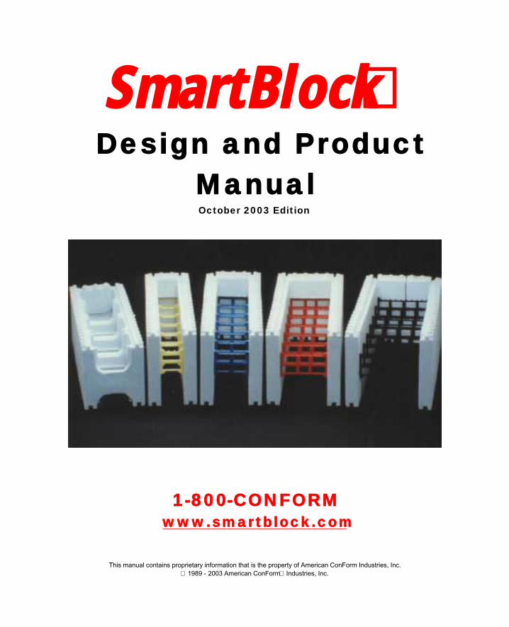
SmartBlock Design and Product
Manual October 2003 Edition
1-800-CONFORM www.smartblock.com
This manual contains proprietary information that is the property of American ConForm Industries, Inc. 1989 - 2003 American ConForm Industries, Inc.

i
SmartBlock™ Design and Product Manual October 2003 Edition
TABLE OF CONTENTS EXHIBIT PAGE
Chapter 1 INTRODUCTION
1.1 Introduction 5
1.2 What is EPS? 7
Chapter 2 SITE WORK AND FOUNDATIONS
2.1 Site Work - Monolithic Pours 8
2.2 Forming Fabrication 8
2.3 Foundation Systems 9
2.3.1 Slab on Grade 8
2.3.2 Stem Wall Foundation 10
Chapter 3 BUILDING WALLS
3.1 Footings 11
3.2 Reinforcing Steel 12
3.3 Ledgers 12
3.4 Lintels 13
3.5 Plates 13
3.6 Lateral Design 13
3.7 Structural Design 14
3.7.1 SF10 Series 14
3.7.1A Flexural Design Capacity 14
3.7.1B Allowable Lateral Loads 15
3.7.1C Allowable Axial Loads 15
3.7.2 VWF Series 16
3.8 Bracing Techniques 17
ii
Chapter 4 INTERIOR FINISHES
4.1 Gypsum Wall Board 26
4.1.1 Horizontal Metal Strips 26
4.1.2 The SmartTach Anchor System 27
4.1.3 The SmartTach Installation Details 28
4.1.4 Other Attachment Methods 29
Chapter 5 DOORS & WINDOWS
5.1 Frames 30
5.2 Reinforcing Steel 31
Chapter 6 EXTERIOR FINISH MATERIALS
6.1 Below Grade Waterproofing 32
6.1.1 Liquid Emulsified Products 33
6.1.2 Sheet Goods 34
6.1.3 Acrylic Based Cements 34
6.1.4 Compatible Waterproofing Product List 35
6.2 Above Grade Exterior Finishes 37
6.2.1 Exterior Insulation Finish Systems 38
6.2.2 One Coat Stucco 38
6.2.3 Polymer Based Stuccos 39
6.2.4 Compatible Exterior Stucco List 40
6.3 Compatible Adhesive List 42
Chapter 7 PLUMBING AND ELECTRICAL
7.1 Introduction to Plumbing and Electrical 43
7.2 Plumbing 43
7.2.1 Direct Embedment 43
7.2.2 Protection of Pipes 44
7.2.3 Installation Recommendations 44
7.2.4 Support of Pipes 46
7.3 Electrical 46
Chapter 8 MANUFACTURERS SPECIFICATIONS
8.1 Manufacturers Technical Specifications 48
8.2 Energy Analysis 50
iii
8.2.1 SF10 Series 50
8.2.2 VWF Series 50
8.3 Sound Transmission 52
8.4 Concrete Specifications 53
8.5 Concrete Estimation 54
8.6 Block Estimation 55
8.7 Tools and Materials 56
8.8 Radius Cut Outs 57
Chapter 9 DESIGN DETAILS
9.1 Design Section 60
Table A - Retaining Wall Chart (3’-6’) 61
Table B - Retaining Wall Chart (8’) 66
Table C - Retaining Wall Chart (10’) 67
Table D - Stem Wall Foundations - Wood Frame Walls 68
Table E - Full Height SmartBlock Walls 68
9.2 Detail Section 69
1.0 - Controlled Ventilated Crawl Space Detail 70
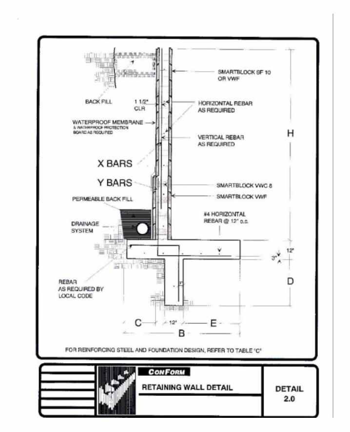
2.0 - Retaining Wall Detail 71
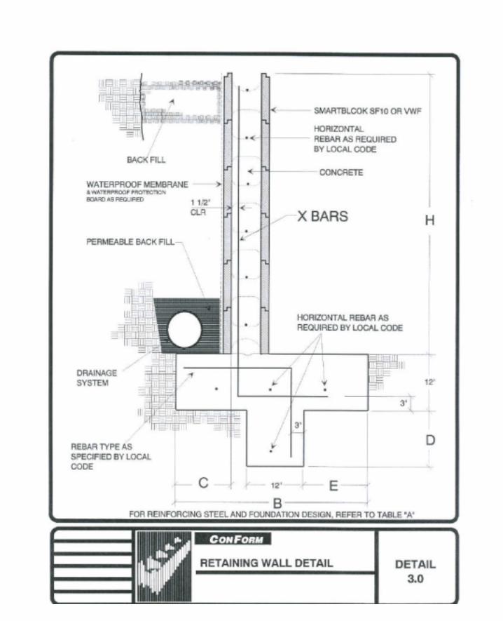
3.0 - Retaining Wall Detail 72
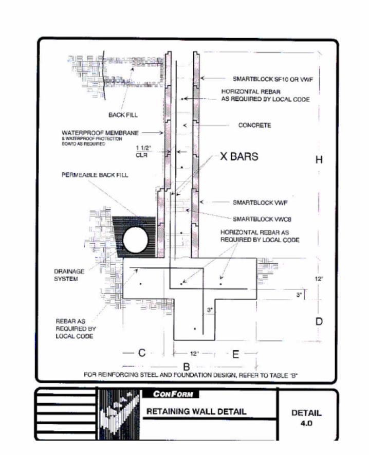
4.0 - Retaining Wall Detail 73
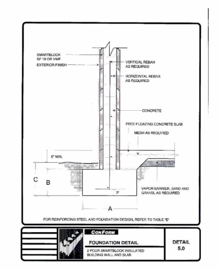
5.0 - Foundation Detail 74
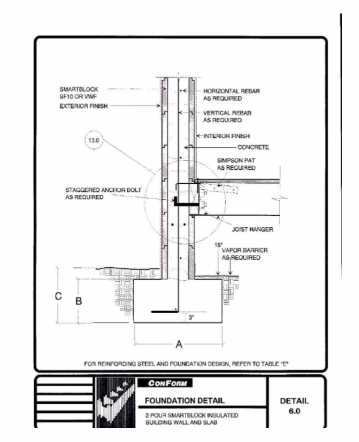
6.0 - Foundation Detail 75
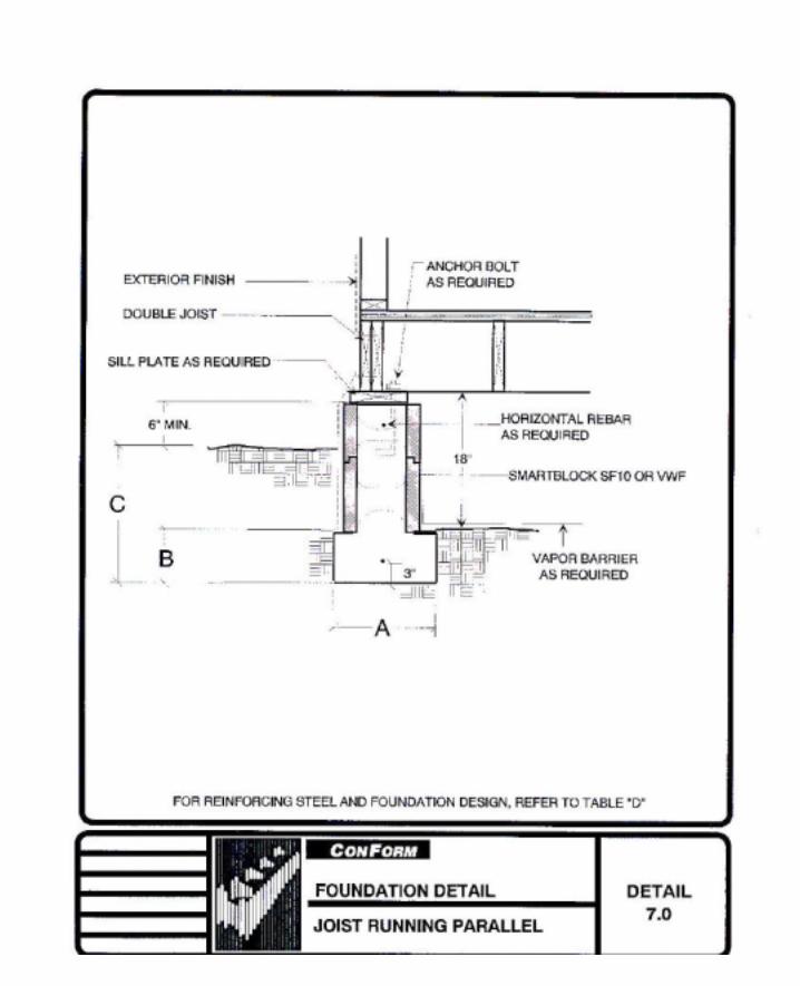
7.0 - Foundation Detail, Joist Running Parallel 76
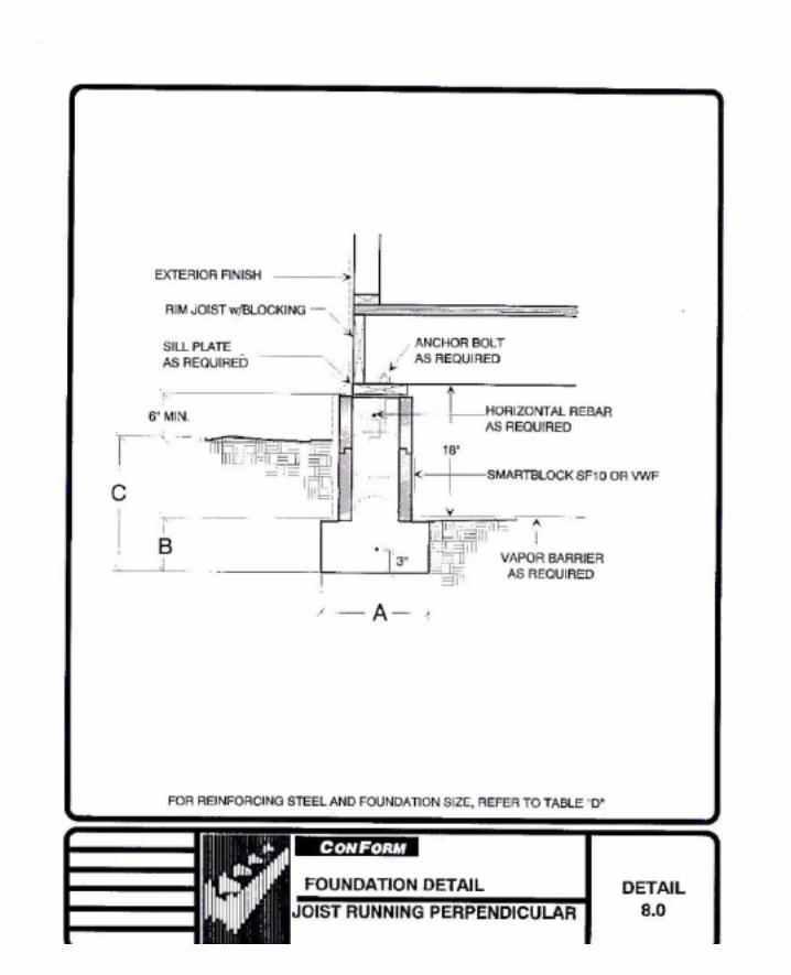
8.0 - Foundation Detail, Joist Running Perpendicular 77
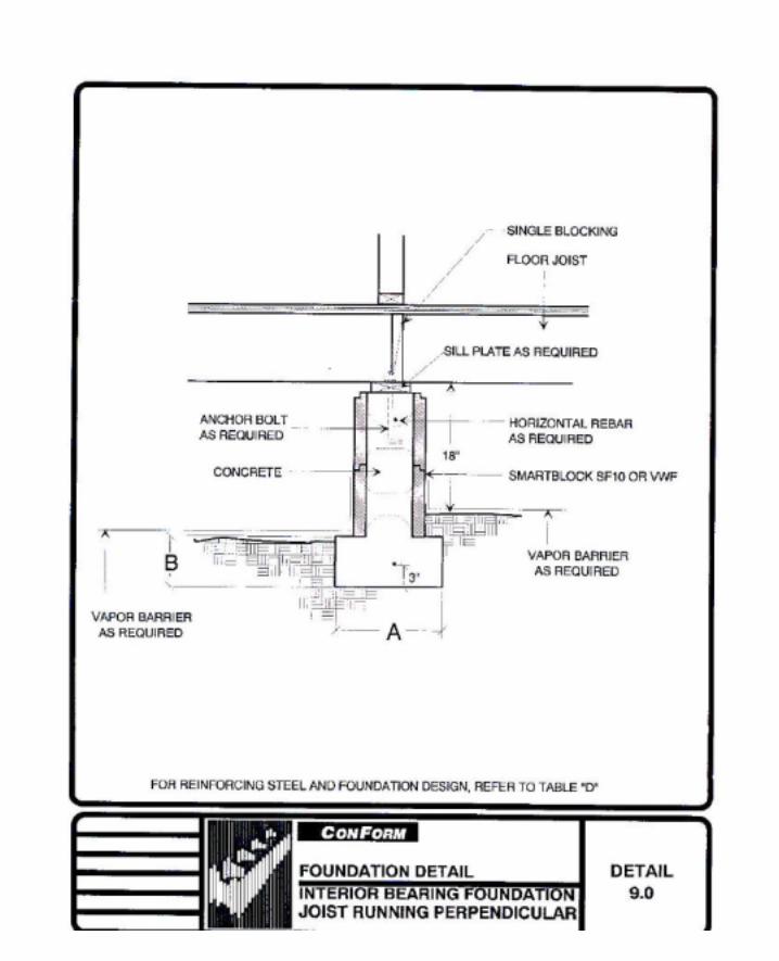
9.0 Foundation Detail, Interior Bearing Foundation, Joist Running Perpendicular 78
10.0 - Foundation Detail, Interior Bearing Foundation, Joist
Running Parallel 79
11.0 - Full Height Wall Section, Two Story 80
12.0 - Ledger Detail, Flush Mounted 81
13.0 - Ledger Detail, Flush Mounted 82
14.0 - Lintel Detail at Eave 83
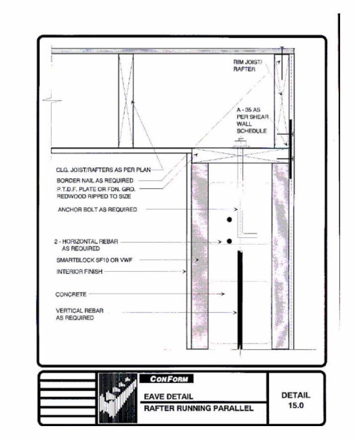
15.0 - Eave Detail, Rafter Running Parallel 84
16.0 - Eave Detail, Rafter Running Perpendicular 85
iv
17.0 - Gyp. Board Attachment Detail, Horiz. Metal Strip Method 86
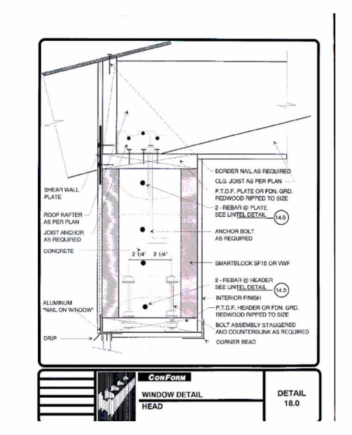
18.0 - Window Detail, Head 87
19.0 - Chase Detail, 3” Vertical Drop at Ledger 88
19.0A - Section “A-A” Plumbing Chase Detail 89
20.0 - Electrical Placement 90
21.0 - Electrical Placement—Alternative View 91
22.0 - Corner Construction 92
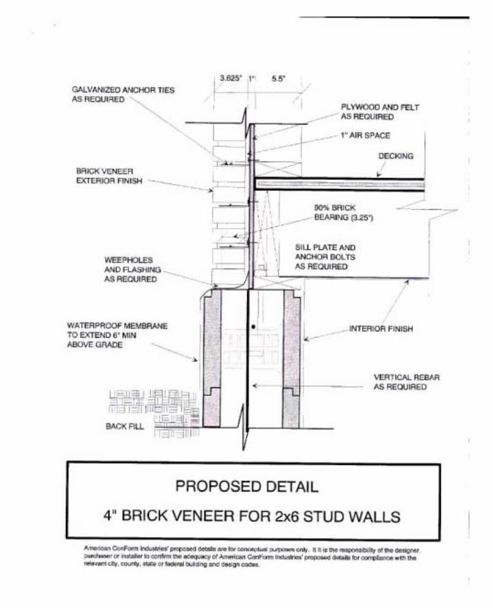
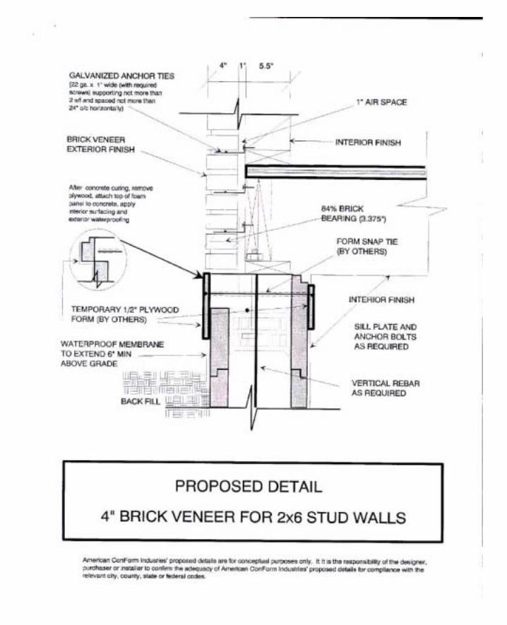
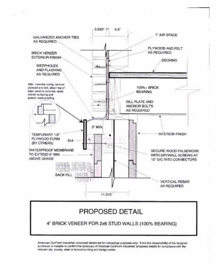
23.0 - 4” Brick Veneer for 2x4 Stud Wall 93
9.3 Miscellaneous Details 94
Chapter 10 SUPPORT REPORTS
10.1 ICBO ES Evaluation Report No. 4572 110
10.2 BOCA Research Report No. 95-46 121
10.3 Wisconsin DILHR Material Approval No. 920083-I 128
10.4 Los Angeles Research Report No. 25006 132
10.5 Texas Department of Insurance – Product Evaluation FR-24 136
10.6 Structural Design Calculations for SF10 Series 139
10.7 CSI Technical Specifications 146

CHAPTER 1 Introduction
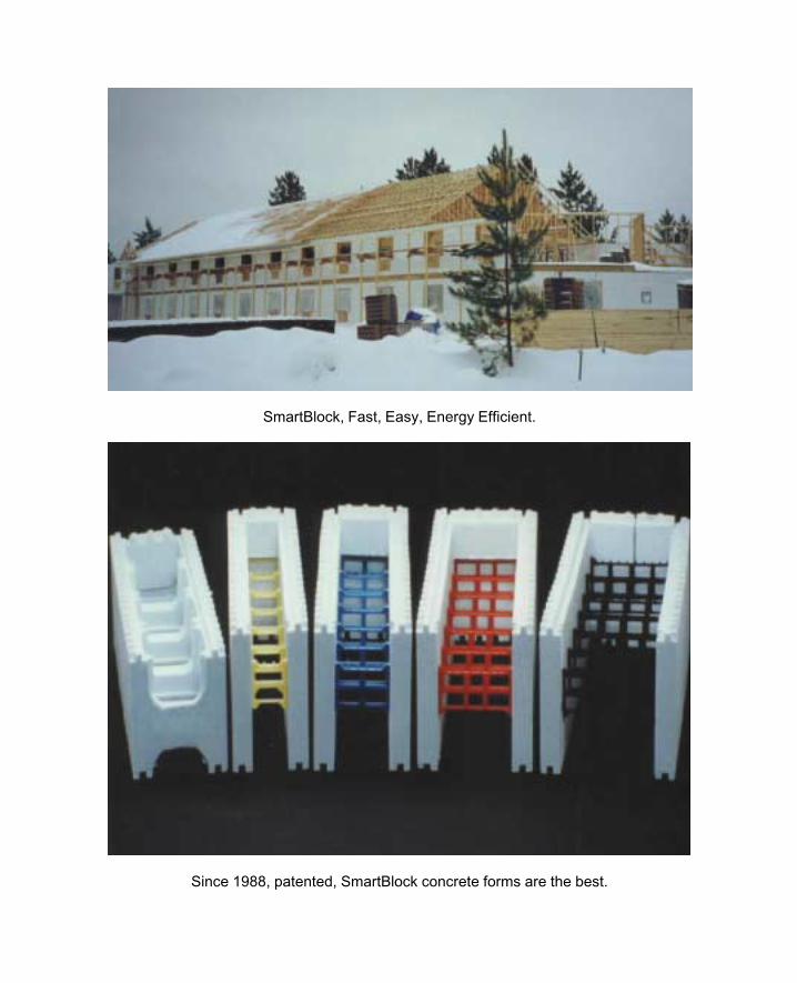
SmartBlock, Fast, Easy, Energy Efficient.
Since 1988, patented, SmartBlock concrete forms are the best.
5
Chapter 1 INTRODUCTION
1.1 Introduction
This manual introduces builders, contractors, architects and engineers to the design parameters
and potential applications of SmartBlock insulating forms.
SmartBlock insulating forms are expanded polystyrene (EPS) forms for pouring concrete load-
bearing, shear and foundation walls. The forms are left in place after concrete is poured and
provide superior insulation relative to conventional wood, concrete and masonry walls.
The units are manufactured in two basic types, Standard Forms (SF10 Series) and Variable
Width Forms (VWF Series). Both forms have rows of interlocking teeth at the top and bottom
to facilitate easy assembly. The form units remain after placing of reinforcing steel and concrete
and must be protected by approved interior and exterior finish materials.
The SF10 Series units are 10 inches high by 10 inches wide by 40 inches long. The face shell
thickness of the SF10 Series is 1¾ inches. When assembled, the units form 7½ inch by 6½
inch rectangular vertical cores at 10 inches on center and 6½ inch by 6¼ inch rectangular
horizontal cores at 10 inches on center.
The VWF Series units are 12 inches high by 40 inches long and can be assembled in varying
widths providing concrete walls of 3¾ inches, 5¾ inches, 7¾ inches, 9¾ inches, 11¾ and other
custom made widths. The average face shell thickness of the VWF Series is 2.125”. The
facing walls of the form are interconnected with eight plastic bridge inserts.
SmartBlock insulating forms are molded from EPS beads manufactured by BASF Corporation
(ICBO Evaluation Report No. 3401) or Huntsman Chemical Corporation (NER-348), having a
density of 1.5 to 2.0 pounds per cubic foot with a maximum flame-spread rating and smoke-
6
density of 10# and 250# respectively, in accordance with the 1991 Uniform Building Code
(UBC) Standard No. 42-1.
SmartBlock insulating forms are recognized by ICBO ES (Evaluation Report No. 4572),
BOCA ES (Research Report No. 95-46), State of New York DHCR (Certificate No. 624-
93-MC), State of Wisconsin DILHR (Approval No. 980020-I), the City of Los Angeles
(Research Report No. 25006) and various city and local building reports.
All users of SmartBlock insulating forms should refer to the enclosed copies of evaluation
reports and reports released after publication of this manual. These reports contain revised
conditions related to the use of SmartBlock insulating forms and should be kept current by all
users of the product. The manufacturer on request will provide updates, but use of SmartBlock
insulating forms must be coordinated with local building officials.
The design concepts within this manual use industry standards for most typical applications.
Trade and material associations have been consulted to verify the workability of the product and
to ensure that these assemblies address general field conditions. Since specifics vary depending
on local conditions, it is imperative that the individual project architect or engineer review all
details, specifications and calculations. Structural designs and calculations are based upon
normal allowable forces and loads, and tables are included to show a variety of applications for
SmartBlock insulating forms. Due to varying load conditions and building codes, each project
should be reviewed and approved by the project architect or engineer.
7
1.2 What Is Expanded Polystyrene (EPS)?
The use of EPS as formwork for concrete has a history in Europe dating back to 1950s. The
use of EPS as formwork evolved from its use as an insulating material in construction.
There are two common types of polystyrene foam, extruded polystyrene (popularly known by
its Dow trademark Styrofoam) and expanded polystyrene or EPS. Most food service
applications including meat trays, egg cartons, hamburger clam shells, foam plates and trays are
extruded polystyrene, as are most types of loose-fill packaging. However, the common coffee
cup is made of EPS. Almost all industrial cushion packaging - the cellular white molded foam
that is used to package televisions, stereos, computers and delicate electronic equipment, as
well as other fragile industrial and consumer products - is also of EPS, as are most bicycle
helmets. Both EPS and extruded polystyrene are used extensively as thermal insulation in
industrial, commercial and residential construction.
As a raw material, EPS is produced in the form of white granules ranging in size from 8/1000ths
to 12/1000ths of an inch. These granules, commonly referred to as bead or resin, feel
something like very fine, polished sand. Three processing stages - prefoaming, intermediate
storage and final foaming - turn the bead into rigid foamed plastic shapes, which in this case are
SmartBlock insulating form units.
Unlike extruded polystyrene, EPS contains no chlorofluorocarbons (CFC’s). EPS is inert and
is less toxic than wood when burned. The EPS used in SmartBlock insulating forms contains
fire resistant additives, which do not allow it to sustain a flame.

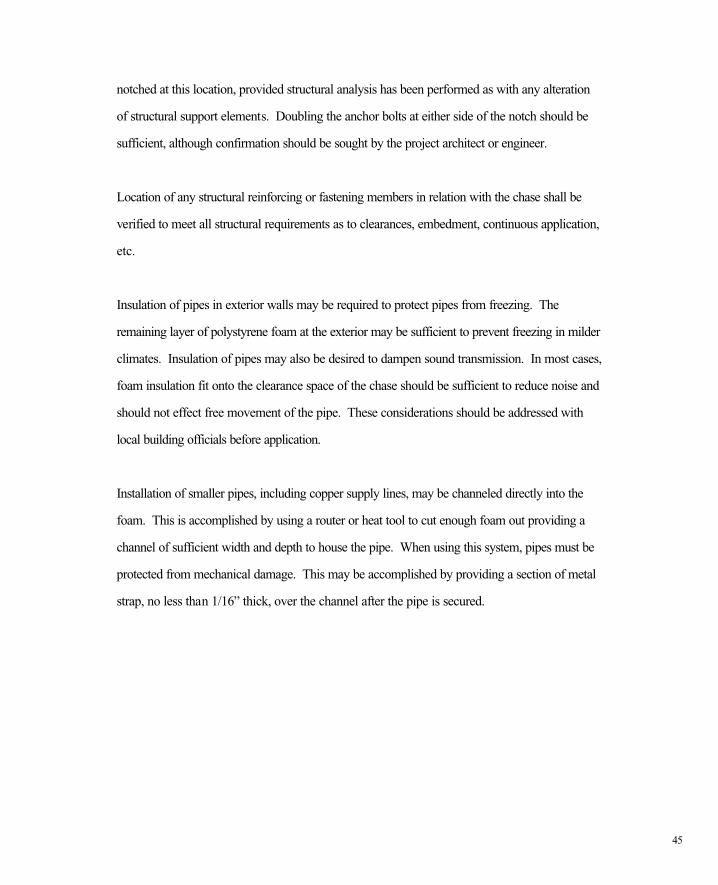
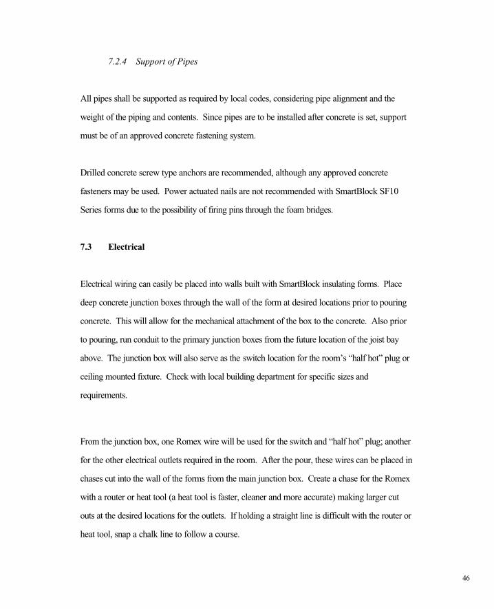
CHAPTER 2 Side Work and Foundations
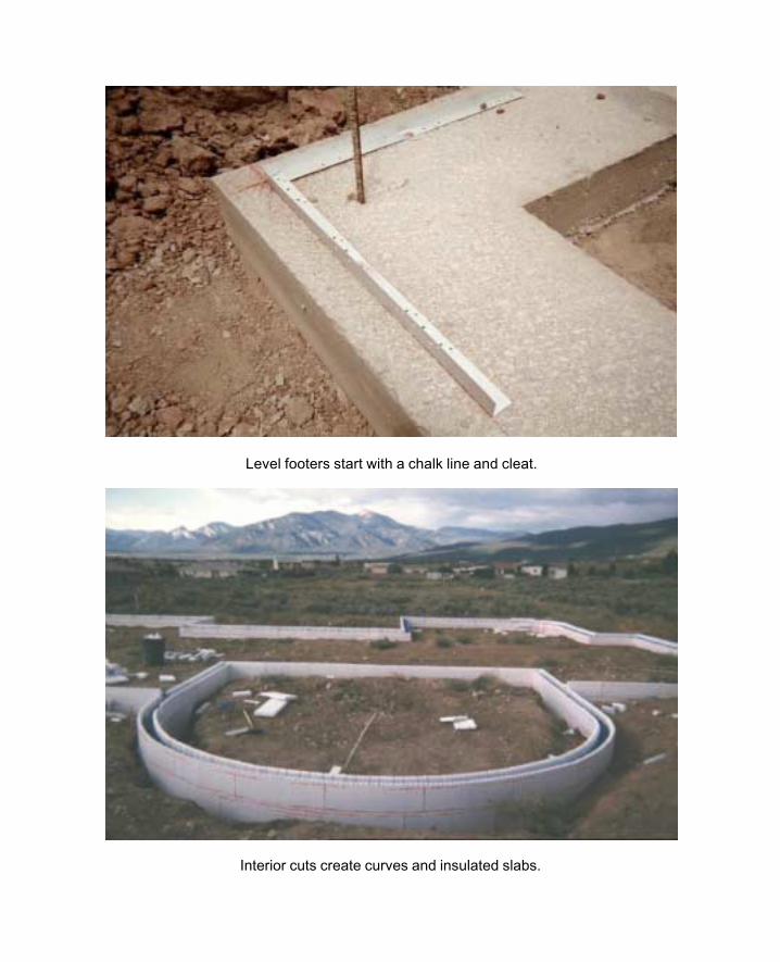
Level footers start with a chalk line and cleat.
Interior cuts create curves and insulated slabs.
8
Chapter 2 SITE WORK AND FOUNDATIONS
2.1 Site Work - Monolithic Pours
Monolithic pour sites are prepared for construction of SmartBlock form walls in the same
manner as for other common foundation forming systems. Set batter boards beyond all corners
and stretch string lines across the location of the exterior faces of the walls. This procedure will
locate the position of the corners. Using a plumb bob, set flag nails directly below the string at a
distance of 4 to 6 feet apart, 1-foot from each corner. After completing the perimeter of the
building, set a stake at each flag nail. Once the exterior stakes are in place, add an additional
nail 1½” to the outside of the string location on the batter boards to offset the string. This will
move the string out of the way for the next step and provide a wall alignment guide. Using stake
material, build a spreader in an “L” shape: the bottom leg of the “L” should be 9¼” in length.
Using the spreader, line up with the existing stake facing towards the interior of the building,
setting interior rows of stakes directly opposite of exterior stakes. This setting of interior stakes
will produce a ¾” toe-in that will hold SmartBlock insulating forms steady during pouring.
2.2 Forming Fabrication
Once the stakes are set, bottom horizontal rebar may be set as needed to satisfy foundation
construction requirements. Calculate the required form height by subtracting the sub floor and
sill depths and mark elevation on stakes. Two courses of SmartBlock insulating forms can be
assembled and slid between stakes to a point of minimum depth of spread footing and held in
place by the toe-in of the stakes. Subsequent rows of forms can be added setting vertical and
horizontal rebar as required. Once forms are in place to the required elevation, as marked on
the stakes, and all rebar is in place, stakes should be held together at the top using SmartBlock
box clips. The foundation should now be ready for inspection and may be poured upon
approval. While pouring, use a 2” x 4” with the 1½” string offset to check wall for alignment.
9
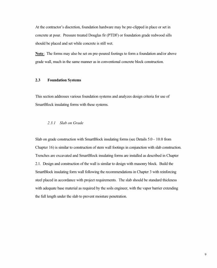
At the contractor’s discretion, foundation hardware may be pre-clipped in place or set in
concrete at pour. Pressure treated Douglas fir (PTDF) or foundation grade redwood sills
should be placed and set while concrete is still wet.
Note: The forms may also be set on pre-poured footings to form a foundation and/or above
grade wall, much in the same manner as in conventional concrete block construction.
2.3 Foundation Systems
This section addresses various foundation systems and analyzes design criteria for use of
SmartBlock insulating forms with these systems.
2.3.1 Slab on Grade
Slab on grade construction with SmartBlock insulating forms (see Details 5.0 - 10.0 from
Chapter 16) is similar to construction of stem wall footings in conjunction with slab construction.
Trenches are excavated and SmartBlock insulating forms are installed as described in Chapter
2.1. Design and construction of the wall is similar to design with masonry block. Build the
SmartBlock insulating form wall following the recommendations in Chapter 3 with reinforcing
steel placed in accordance with project requirements. The slab should be standard thickness
with adequate base material as required by the soils engineer, with the vapor barrier extending
the full length under the slab to prevent moisture penetration.
10
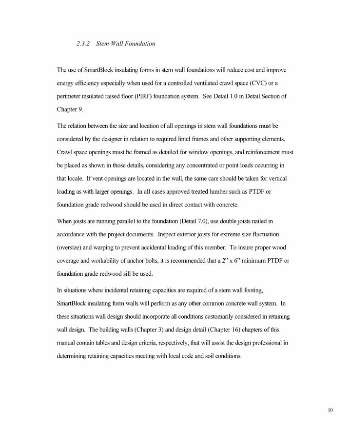
2.3.2 Stem Wall Foundation
The use of SmartBlock insulating forms in stem wall foundations will reduce cost and improve
energy efficiency especially when used for a controlled ventilated crawl space (CVC) or a
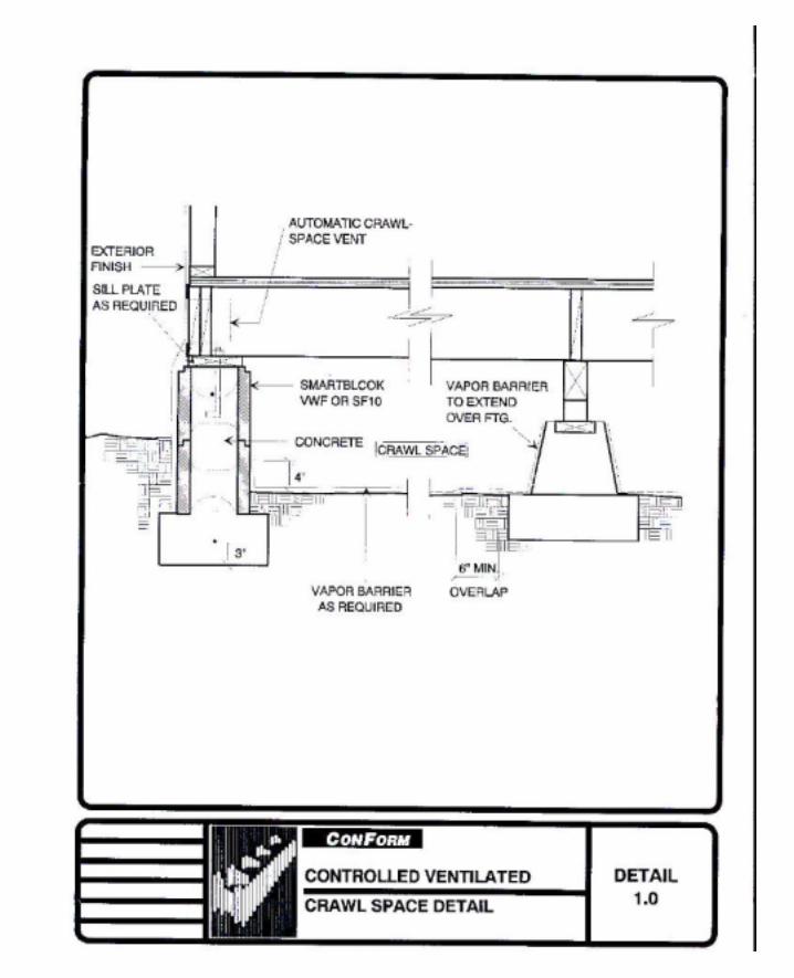
perimeter insulated raised floor (PIRF) foundation system. See Detail 1.0 in Detail Section of
Chapter 9.
The relation between the size and location of all openings in stem wall foundations must be
considered by the designer in relation to required lintel frames and other supporting elements.
Crawl space openings must be framed as detailed for window openings, and reinforcement must
be placed as shown in those details, considering any concentrated or point loads occurring in
that locale. If vent openings are located in the wall, the same care should be taken for vertical
loading as with larger openings. In all cases approved treated lumber such as PTDF or
foundation grade redwood should be used in direct contact with concrete.
When joists are running parallel to the foundation (Detail 7.0), use double joists nailed in
accordance with the project documents. Inspect exterior joists for extreme size fluctuation
(oversize) and warping to prevent accidental loading of this member. To insure proper wood
coverage and workability of anchor bolts, it is recommended that a 2” x 6” minimum PTDF or
foundation grade redwood sill be used.
In situations where incidental retaining capacities are required of a stem wall footing,
SmartBlock insulating form walls will perform as any other common concrete wall system. In
these situations wall design should incorporate all conditions customarily considered in retaining
wall design. The building walls (Chapter 3) and design detail (Chapter 16) chapters of this
manual contain tables and design criteria, respectively, that will assist the design professional in
determining retaining capacities meeting with local code and soil conditions.


CHAPTER 3 Building Walls
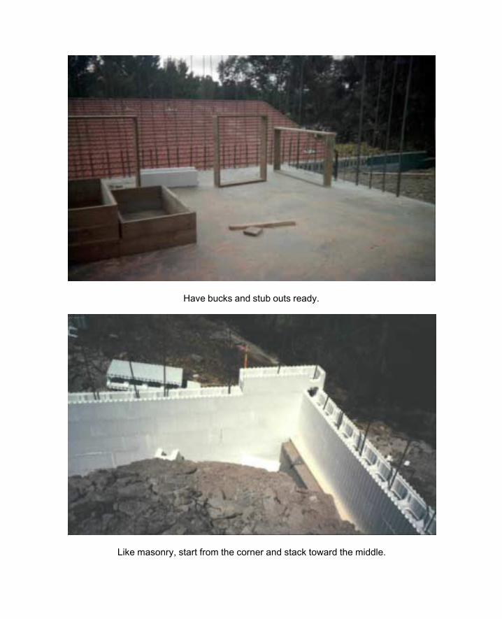
Have bucks and stub outs ready.
Like masonry, start from the corner and stack toward the middle.

11
Chapter 3: BUILDING WALLS
This chapter addresses design aspects of the use of SmartBlock insulating forms in the
construction of a building wall.
SmartBlock SF10 insulating forms can be used in exterior or interior bearing or non-bearing
walls to an unsupported height of 10 ft. for 2 story construction in accordance with Finding #2
of ICBO ES Evaluation Report No. 4572. Higher building walls can be constructed with the
SmartBlock VWF Series forms or with the SF10 Series by specific design by an architect or
engineer.
This manual contains details and tables for use of SmartBlock SF10 Series insulating forms in
building wall construction in accordance with ICBO ES Evaluation Report No. 4572, and
BOCA Research Report No. 95-46.
3.1 Footings
Building walls constructed with SmartBlock insulating forms require an increase in spread
footings sizes compared with conventional wood frame construction, due to the increased
weight of concrete walls. This increased size acts to and compensate for shear at the wall plane
at the footing. In tables A, B, C, D and E in Design Section of Chapter 9, soil bearing
pressures are assumed to be 1000 psf. Individual soils analysis may reduce or increase these
sizes.
12
3.2 Reinforcing Steel
Suggested reinforcing steel requirements, sizes and spacings are identified throughout in
this manual. Reinforcement parameters should be in accordance with specific project design
requirements.
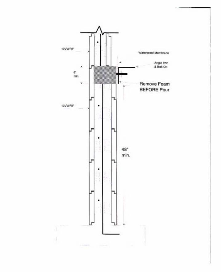
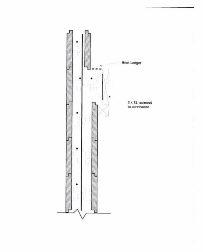
3.3 Ledgers
In typical reinforced concrete or masonry construction, floors are supported by the use of a
ledger (see Details 6.0, 12.0 and 13.0). Before the pour, to avoid cantilevering the anchor bolts
used in the ledger, the SmartBlock insulating forms should be cut to allow proper surrounding of
"J" bolts with concrete. Due to the thickness of the concrete cell, embedment requirements
should be addressed in all ledgers and ledger bolt designs. Horizontal diaphragm shear may be
transferred to the wall at this point and should be designed for each project.
To facilitate placement of reinforcing steel, all door and window openings should be constructed
as fabrication proceeds rather than waiting until forming is complete. UBC requires that two
No. 5 rebars are placed vertically and horizontally at each opening and the ends of the bars
should extend a minimum of 24” beyond the corners of the opening. In the case of the
restricted area past the corner of an opening, the bar may be bent to tie to the nearest horizontal
or vertical reinforcing bar.
13
3.4 Lintels
Lintels over openings may be constructed as shown in Detail No. 14.0. The distance between
the top and bottom reinforcing steel governs the strength of the lintel so rebar placement is
critical. If foam bridging in the SF10 Series restricts placement of rebar around lintels, VWF
Series may be substituted. All lintel applications must be reviewed and approved by the project
architect or engineer.
3.5 Plates
The top plate may be installed in the same manner as common with other construction methods.
The plate should consist of PTDF, foundation grade redwood or an approved equal. Due to
shear forces at this level, anchor bolt spacings are designed depending on the size of plate used.
Refer to table No. 25-F in the UBC for specific design parameters. Applications must be
reviewed for compliance with local codes and conditions.
3.6 Lateral Design
Lateral design is addressed in various details showing typical nailing, clips, anchor bolts, etc.
used in the field for shear transfer (see Chapter 16 - Details 6.0, 7.0, 8.0, 9.0, 10.0, 12.0, 13.0,
15.0 and 16.0 ). These details show possible solutions that must be designed in connection with
lateral design. Each project must be analyzed individually since specific building design and
local codes govern parameters of lateral design.
14
3.7 Structural Design
Unlike masonry walls that derive some structural value from concrete masonry units
(CMU’s), the SmartBlock insulating form contributes no structural value to the wall system.
The structural strength of SmartBlock insulating form walls is provided solely by the reinforced
concrete structure contained within the SmartBlock insulating forms.
3.7.1 SF10 Series
Section 10.6 of this manual contains a table of the allowable (factored) bending
moments, lateral loads and axial loads of a concrete wall formed with SF10 Series insulating
forms along with the supporting calculations for use by the design engineer and building officials.
The structural design capacities of the 6½ inch wide concrete wall contained within the
SF10 Series insulating forms are in accordance with Chapter 19 of the 1997 UBC. However,
the structural capacity of the SF10 Series wall is slightly reduced (compared to a solid 6½ inch
wide concrete wall) because of the displacement of concrete by the 2½ inch by 3½ inch EPS
bridges spaced on a 10 inch by 10 inch grid pattern.
3.7.1A Flexural Design Capacity
Since the 2½ inch wide EPS bridges in the SF10 Series block are spaced 10 inches
apart horizontally, the effective width or “b” dimension of a SmartBlock insulating form wall is
reduced 25% as compared to a solid concrete wall. Therefore, the “b” dimension per lineal
foot of wall in the following equation:
a = Asfy / .85f’cb
15
is 9 inches in lieu of the standard 12 inch dimension customary for wall design. Once the
modified “b” dimension is calculated, calculation of the allowable moment is identical to a solid
concrete wall design using the following equation:
fM = fAsfy (d - a/2)
3.7.1B Allowable Lateral Loads
Similar to flexural design, the “b” dimension in the following equation:
fV = f2Öf’c (b)d
is 9 inches in lieu of the customary 12 inches for solid wall design.
3.7.1C Allowable Axial Loads
For the 6½ inch wide wall, the presence of the EPS bridges effects the axial load
capacity of the wall by reducing Ag in the following equation:
fP = .55ff’cAg[1 - (Klc/32h)2]
Ag for the SF10 Series wall is 58.5 square inches (6.5 inches x 9 inches) in lieu of 78 square
inches (6.5 inches x 12 inches) for a solid 6½ inch wall.
16
3.7.2 VWF Series
The VWF Series blocks are connected by plastic ties similar in size to ties used for
conventionally formed concrete. Therefore, the structural capacities of walls using the VWF
Series blocks are the same as for other concrete forming methods. These capacities may be
calculated in accordance with Chapter 19 of the 1997 UBC for concrete wall widths of 3 ¾
inches, 5 ¾ inches, 7 ¾ inches, 9 ¾ inches and 11 ¾ inches.

17
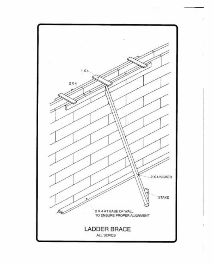
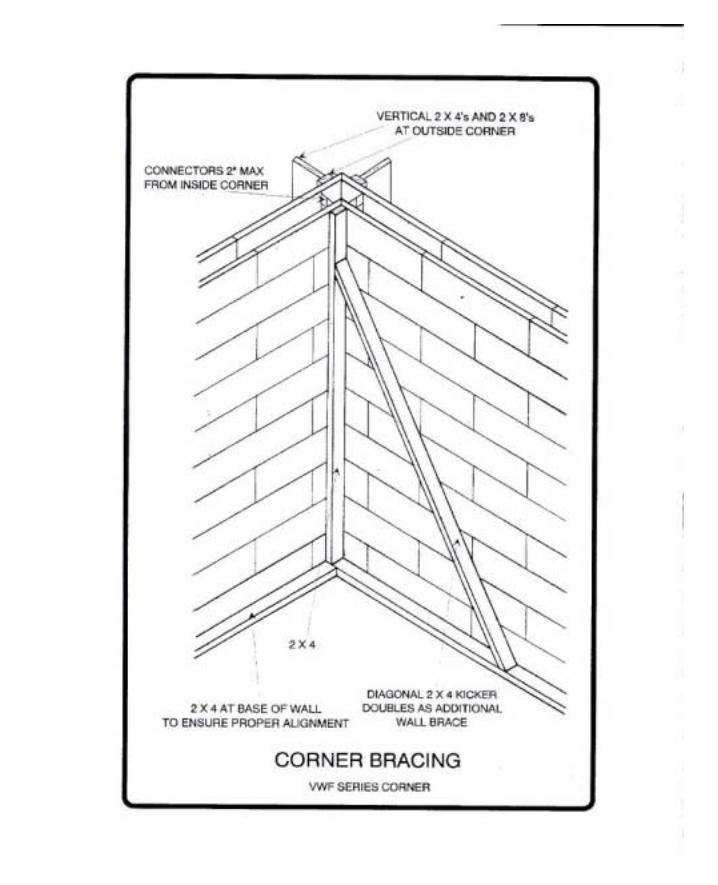
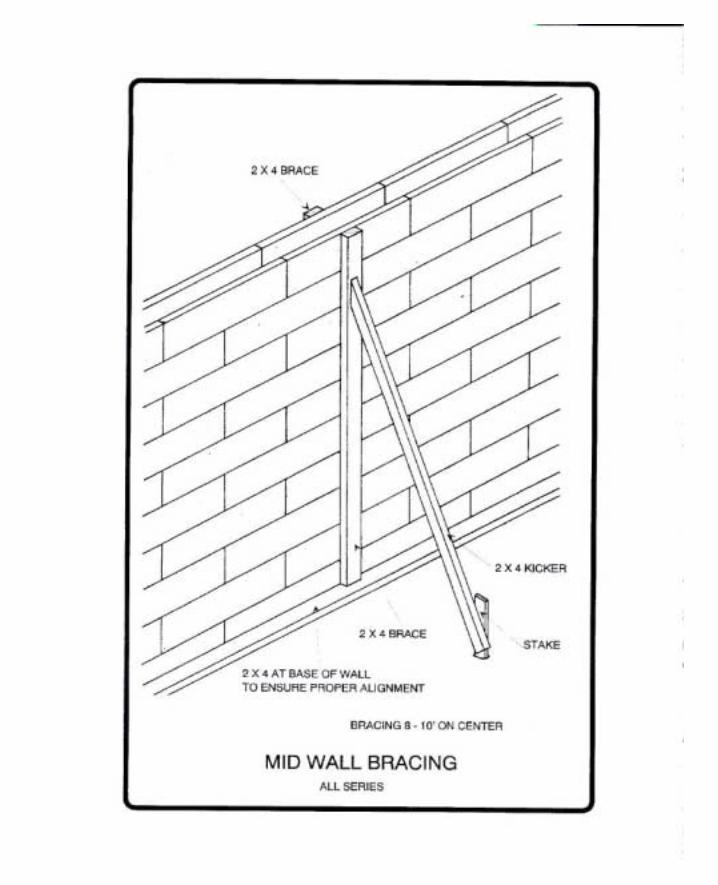
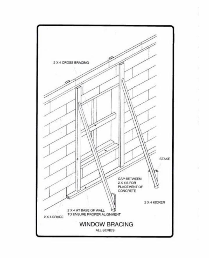
3.8 Bracing Techniques
Smart BlockSmart Block BRACING TECHNIQUES
NOTE: The drawing represent possible methods of supplying alignment support for your Smart Block wall. They are intended to be use as guided only, and are not to scale.
Proper support will vary depending upon site condition, concrete pressures, wall height, soil
capacities and the overall building system being incorporated or architect for precise
bracing requirements.


CHAPTER 4 Interior Finishes
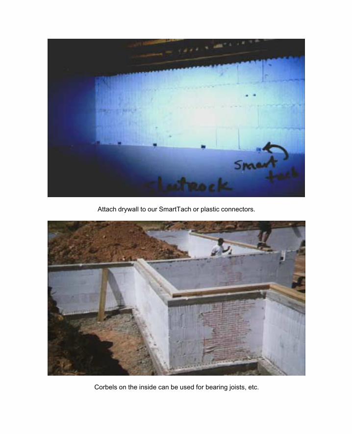
Attach drywall to our SmartTach or plastic connectors.
Corbels on the inside can be used for bearing joists, etc.
26
Chapter 4 INTERIOR FINISHES
This chapter addresses the methods of attaching an approved 15 minute thermal barrier over
SmartBlock insulating forms as required by Chapter 26 of the 1997 UBC.
4.1 Gypsum Wall Board
All habitable areas of structures built with a SmartBlock insulating forms are required to be separated from the EPS by a thermal barrier having an index of 15. (See UBC Chapter 26.) The most common method is the use of gypsum wall board (GWB), also referred to as drywall. A minimum thickness of 1/2" is required to meet this condition. The 1997 UBC Chapter 25, which outlines the conventional methods of attaching drywall, requires that screws or nails be attached, as a minimum, 18" on center whether the drywall is attached horizontally or vertically.
4.1.1 Metal Clips
At present, the UBC does not specifically address attaching drywall to SmartBlock insulating
forms. The UBC does state, however, that a test can be used as an alternative to the standard
methods of attachment for thermal barriers. SmartBlock insulating forms were tested using
metal clips that provide mechanical attachment with the concrete and a fastening surface for
drywall screws.
27
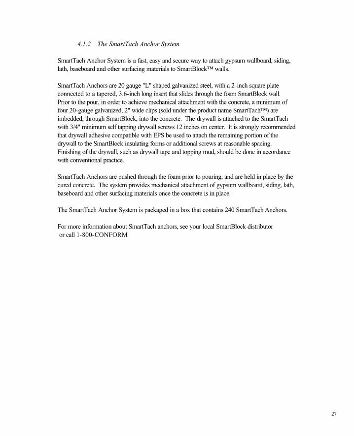
4.1.2 The SmartTach Anchor System SmartTach Anchor System is a fast, easy and secure way to attach gypsum wallboard, siding, lath, baseboard and other surfacing materials to SmartBlock™ walls. SmartTach Anchors are 20 gauge "L" shaped galvanized steel, with a 2-inch square plate connected to a tapered, 3.6-inch long insert that slides through the foam SmartBlock wall. Prior to the pour, in order to achieve mechanical attachment with the concrete, a minimum of four 20-gauge galvanized, 2" wide clips (sold under the product name SmartTach™) are imbedded, through SmartBlock, into the concrete. The drywall is attached to the SmartTach with 3/4" minimum self tapping drywall screws 12 inches on center. It is strongly recommended that drywall adhesive compatible with EPS be used to attach the remaining portion of the drywall to the SmartBlock insulating forms or additional screws at reasonable spacing. Finishing of the drywall, such as drywall tape and topping mud, should be done in accordance with conventional practice. SmartTach Anchors are pushed through the foam prior to pouring, and are held in place by the cured concrete. The system provides mechanical attachment of gypsum wallboard, siding, lath, baseboard and other surfacing materials once the concrete is in place. The SmartTach Anchor System is packaged in a box that contains 240 SmartTach Anchors. For more information about SmartTach anchors, see your local SmartBlock distributor or call 1-800-CONFORM
28
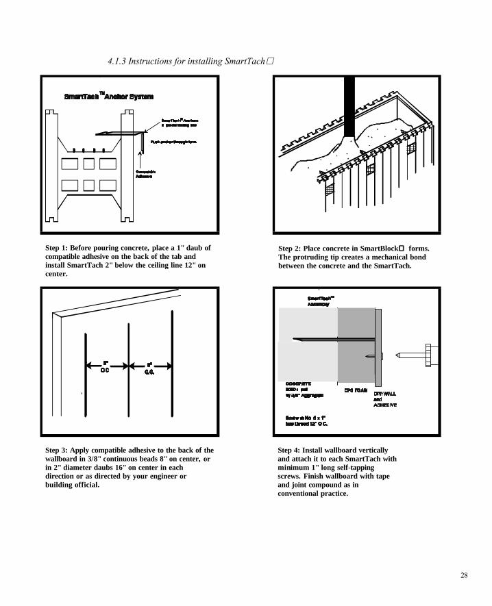
4.1.3 Instructions for installing SmartTach
Step 1: Before pouring concrete, place a 1" daub of compatible adhesive on the back of the tab and install SmartTach 2" below the ceiling line 12" on center.
Step 2: Place concrete in SmartBlock forms. The protruding tip creates a mechanical bond between the concrete and the SmartTach.
Step 3: Apply compatible adhesive to the back of the wallboard in 3/8" continuous beads 8" on center, or in 2" diameter daubs 16" on center in each direction or as directed by your engineer or building official.
Step 4: Install wallboard vertically and attach it to each SmartTach with minimum 1" long self-tapping screws. Finish wallboard with tape and joint compound as in conventional practice.
29
4.1.3 Other Attachment Methods
Attaching drywall to the top wood plate instead of the metal strip described above should be
sufficient to achieve the required thermal barrier. In order to achieve the required 15 minute
thermal barrier over SmartBlock insulating forms as stipulated in Section 1713 of the 1991
UBC, you need only attach the drywall to the top strip. No other attachment is required
although use of a drywall adhesive to assure a smooth and problem free surface is strongly
recommended.
CHAPTER 5 Doors and Windows
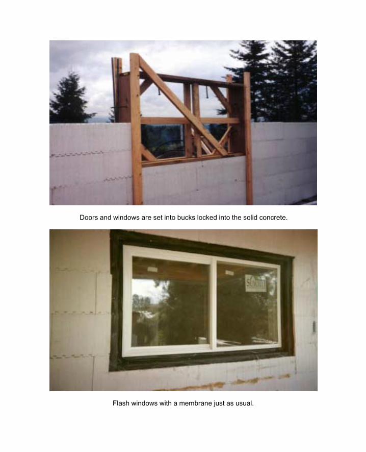
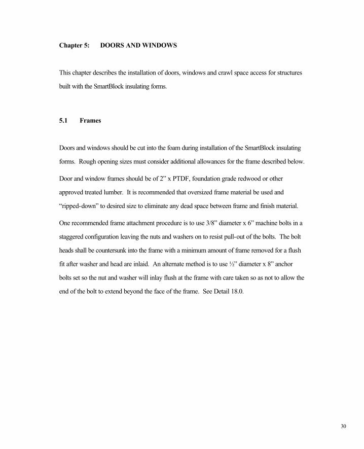
Doors and windows are set into bucks locked into the solid concrete.
Flash windows with a membrane just as usual.
30
Chapter 5: DOORS AND WINDOWS
This chapter describes the installation of doors, windows and crawl space access for structures
built with the SmartBlock insulating forms.
5.1 Frames
Doors and windows should be cut into the foam during installation of the SmartBlock insulating
forms. Rough opening sizes must consider additional allowances for the frame described below.
Door and window frames should be of 2” x PTDF, foundation grade redwood or other
approved treated lumber. It is recommended that oversized frame material be used and
“ripped-down” to desired size to eliminate any dead space between frame and finish material.
One recommended frame attachment procedure is to use 3/8” diameter x 6” machine bolts in a
staggered configuration leaving the nuts and washers on to resist pull-out of the bolts. The bolt
heads shall be countersunk into the frame with a minimum amount of frame removed for a flush
fit after washer and head are inlaid. An alternate method is to use ½” diameter x 8” anchor
bolts set so the nut and washer will inlay flush at the frame with care taken so as not to allow the
end of the bolt to extend beyond the face of the frame. See Detail 18.0.
31
5.2 Reinforcing Steel
Reinforcing steel is required to surround all openings in the following manner: 2-#5 reinforcing
steel bars are required both horizontally and vertically around all openings, and must extend a
minimum of 24” beyond the corner of that opening. In the case of the restricted area past the
corner of an opening, the bar may be bent to tie to the nearest horizontal or vertical reinforcing
bar.

CHAPTER 6 Exterior Finish Materials
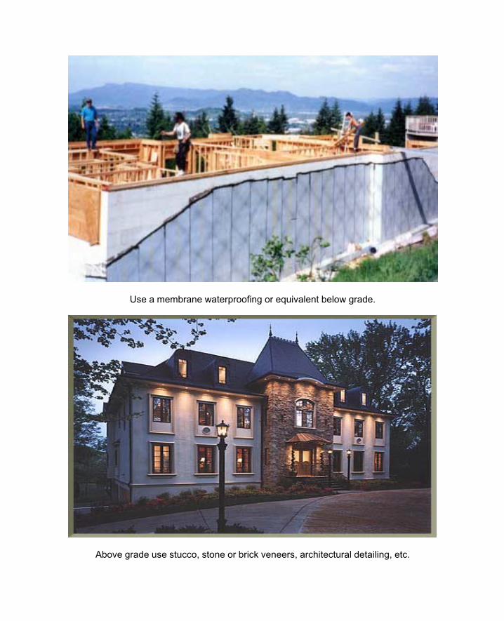
Use a membrane waterproofing or equivalent below grade.
Above grade use stucco, stone or brick veneers, architectural detailing, etc.
32
Chapter 6 EXTERIOR FINISH MATERIALS
The exterior, both above and below grade, of SmartBlock insulating forms must be covered
with a protective and waterproof finish after the reinforcing steel and concrete have been
placed. This chapter describes exterior finishes that may be applied to SmartBlock insulating
forms.
6.1 Below Grade Waterproofing
SmartBlock insulating forms must be waterproofed in below grade applications. Section 6.1.4
contains an approved list of waterproofing products for SmartBlock insulating forms.
SmartBlock insulating forms absorb only 2% by volume in water. In addition, water vapor
transmission allows water to flow through the block. In a below grade structure, water vapor
transmission will damage the interior drywall, causing it to warp and discolor. In the case of a
retaining wall, water vapor transmission caused by inadequate waterproofing will cause the
stucco on the exterior to discolor and possibly to spall off the wall.
EPS is a petroleum by-product that will dissolve when placed in contact with solvents,
keytones, esters, and pitches. It is very important when selecting a waterproofing
product that it is checked for compatibility with EPS. If you are concerned with the
compatibility of a waterproofing product with EPS, call your material distributor or take a small
portion of the product and apply it to a section of a SmartBlock insulating form. If you notice
any disfigurement of the EPS (shrinkage, warping, etc.) within 24 hours, select a different
waterproofing product.
There are many waterproofing products that work well with SmartBlock insulating forms. Most
waterproofing failures are due to improper application, so waterproofing should be applied
according to the manufacturers’ instructions.
33
Waterproofing must be applied thoroughly to cover the SmartBlock insulating form wall leaving
no holes or voids. Any pinholes or voids will permit moisture to infiltrate the wall. Particular
attention should be given to assure that the joints and seams of the forms are sealed.
There are three common types of waterproofing used on EPS: Liquid emulsified products,
sheet goods (membranes) and acrylic based cementitious products.
6.1.1 Liquid Emulsified Products
Liquid emulsified products work well in confined work spaces. The surface of the SmartBlock
insulating forms must be clean and thoroughly dry before the waterproofing is applied. To test
for dryness, tape a 4” square of aluminum foil to the EPS surface of the form being sure to tape
the perimeter edges completely to prevent moisture escape. Allow the foil to remain
undisturbed for 24 hours. Remove the tape carefully, and turn over the aluminum foil. If
moisture is present on the foil then the surface requires additional drying. After thorough
application of waterproofing (this may require 2 coats), protection board, usually ¼” extruded
polystyrene, must be applied over the waterproofing. This is required to prevent damage to the
waterproofing material during backfilling. Waterproofing should be applied to a minimum of 6”
above the planned finish grade in all applications.
34
6.1.2 Sheet Goods
Sheets goods also provide an effective method of waterproofing. The EPS exterior of the
SmartBlock insulating forms must be clean and thoroughly dry, as required for liquid emulsified
waterproofing. Sheet goods are placed on the wall, then the seams must be sealed with an
adhesive strip. Do not use a system that requires the seams to be torch sealed as this may
cause the SmartBlock insulating forms to melt. The same use and application of protection
board is required as with the emulsified materials.
6.1.3 Acrylic Based Cements
Cement products that contain acrylic bases are also commonly used for waterproofing. The
application is the same as for emulsified materials except that this material may be colored and
may be applied to the entire wall both above grade and below grade. The main benefit to this
particular type of application is in its aesthetic appearance. However, because it is a cement
product it does not have the same expansion and contraction and freeze thaw durability as the
other methods.
35
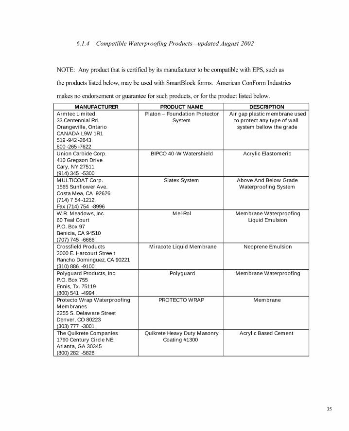
6.1.4 Compatible Waterproofing Products—updated August 2002
NOTE: Any product that is certified by its manufacturer to be compatible with EPS, such as
the products listed below, may be used with SmartBlock forms. American ConForm Industries
makes no endorsement or guarantee for such products, or for the product listed below.
MANUFACTURER PRODUCT NAME DESCRIPTION Armtec Limited 33 Centennial Rd. Orangeville, Ontario CANADA L9W 1R1 519 -942 -2643 800 -265 -7622
Platon – Foundation Protector System
Air gap plastic membrane used to protect any type of wall system bellow the grade
Union Carbide Corp. 410 Gregson Drive Cary, NY 27511 (914) 345 -5300
BIPCO 40 -W Watershield Acrylic Elastomeric
MULTICOAT Corp. 1565 Sunflower Ave. Costa Mea, CA 92626 (714) 7 54 -1212 Fax (714) 754 -8996
Slatex System Above And Below Grade Waterproofing System
W.R. Meadows, Inc. 60 Teal Court P.O. Box 97 Benicia, CA 94510 (707) 745 -6666
Mel-Rol Membrane Waterproofing Liquid Emulsion
Crossfield Products 3000 E. Harcourt Stree t Rancho Dominguez, CA 90221 (310) 886 -9100
Miracote Liquid Membrane Neoprene Emulsion
Polyguard Products, Inc. P.O. Box 755 Ennis, Tx. 75119 (800) 541 -4994
Polyguard Membrane Waterproofing
Protecto Wrap Waterproofing Membranes 2255 S. Delaware Street Denver, CO 80223 (303) 777 -3001
PROTECTO WRAP Membrane
The Quikrete Companies 1790 Century Circle NE Atlanta, GA 30345 (800) 282 -5828
Quikrete Heavy Duty Masonry Coating #1300
Acrylic Based Cement
36
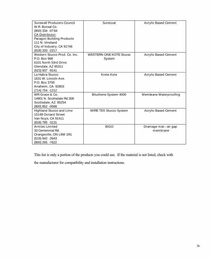
Surewall Producers Council W.R. Bonsal Co. (800) 334 -0784 CA Distributor: Paragon Building Products 111 N. Vineland City of Industry, CA 91746 (818) 333 -2217
Surecoat Acrylic Based Cement
Western Stucco Prod. Co. Inc. P.O. Box 968 6101 North 53rd Drive Glendale, AZ 95311 (623) 937 -9141
WESTERN ONE KOTE Stucco System
Acrylic Based Cement
La Habra Stucco 1631 W. Lincoln Ave. P.O. Box 3700 Anaheim, CA 92803 (714) 754 -1212
Krete Kote Acrylic Based Cement
WR Grace & Co. 14901 N. Scottsdale Rd.306 Scottsdale, AZ 85254 (800) 852 -0568
Bituthene System 4000 Membrane Waterproofing
Highland Stucco and Lime 15148 Oxnard Street Van Nuys, CA 91411 (818) 785 -3131
WIRE TEX Stucco System Acrylic Based Cement
Armtec Limited 33 Centennial Rd. Orangeville, ON L9W 1R1 (519) 942 -2643 (800) 265 -7622
BIGO Drainage mat – air gap membrane
This list is only a portion of the products you could use. If the material is not listed, check with
the manufacturer for compatibility and installation instructions.
37
6.2 Above Grade Exterior Finishes
This section describes recommended stucco finishes and coatings for use with the SmartBlock
insulating forms. See Section 6.2.4 for stucco list.
38
6.2.1 Exterior Insulation Finish Systems
The first group of coatings are generically known as Exterior Insulation Finish Systems (EIFS).
These systems are designed specifically for exterior EPS construction. The installation sequence
for all EIFS coatings is as follows:
1) Liquid acrylic is mixed with common cement and applied to the EPS surface as a base coat.
2) Fiberglass mesh with ¼” grid is embedded into the base coat.
3) Colored liquid acrylic of varying textures is applied as a finish coat.
The average thickness of EIFS coatings is 1/8”. These systems have color fastness for up to
ten years and are highly resistant to freeze-thaw conditions. In addition they provide a
waterproof coating due to the acrylic additives. The main disadvantage of these systems is their
low impact resistance to puncture. As a result, these coatings are often installed away from high
traffic areas. EIFS coatings also tend to be more expensive than other finishes.
6.2.2 One Coat Stucco
“One coat stucco” is designed for use on exterior EPS construction. The installation sequence
for one coat stucco finishes is typically as follows:
1) Apply pre-mixed base (cement, sand, and cut (approx. 3/8”) acrylic fibers) to the EPS
surface with either a trowel or plaster application gun.
2) Fiberglass mesh, with a ¼” wide grid may be imbedded in the base in areas of high
traffic (below 6’).
3) Apply desired pigment box, also known as color packs, over the base to achieve
desired color finish.
39
The average thickness of these systems is 3/8” to ½”. These finishes have high impact
resistance, are very easy to apply and allow for many texture variations.
6.2.3 Polymer Based Stuccos
Direct liquid or polymer type additives are poured directly into a cement, sand and lime brown
coat mixture. The installation procedure is as follows:
1) Combine cement, sand and lime per manufacturer’s specification in standard cement mixer
or plaster application gun.
2) Add specified amount of liquid polymer per manufacturer’s specification in order to insure
proper chemical bonding of cement base coat to EPS surface.
3) Fiberglass mesh, with ¼” wide grid may be applied in areas of high traffic (below 6’).
4) Finish in stucco-like textures, as required.
5) Apply finish coat of color integral stucco or paint with acrylic exterior paint.
The average thickness of this system is 3/8” to ½”. These products are very easy to apply,
have very high impact resistance, especially with applied mesh, and provide a solid waterproof
coating due to the polymer additives.
40
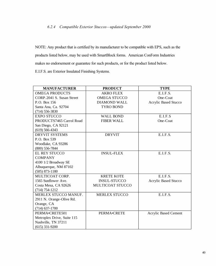
6.2.4 Compatible Exterior Stuccos—updated September 2000
NOTE: Any product that is certified by its manufacturer to be compatible with EPS, such as the
products listed below, may be used with SmartBlock forms. American ConForm Industries
makes no endorsement or guarantee for such products, or for the product listed below.
E.I.F.S. are Exterior Insulated Finishing Systems.
MANUFACTURER PRODUCT TYPE OMEGA PRODUCTS CORP.2041 S. Susan Street P.O. Box 156 Santa Ana, Ca. 92704 (714) 556-3830
AKRO FLEX OMEGA STUCCO DIAMOND WALL
TYRO BOND
E.I.F.S. One-Coat
Acrylic Based Stucco
EXPO STUCCO PRODUCTS7465 Carrol Road San Diego, CA 92121 (619) 566-4343
WALL BOND FIBER WALL
E.I.F.S One-Coat
DRYVIT SYSTEMS P.O. Box 539 Woodlake, CA 93286 (800) 556-7844
DRYVIT E.I.F.S.
EL REY STUCCO COMPANY 4100 1/2 Broadway SE Albuquerque, NM 87102 (505) 873-1180
INSUL-FLEX E.I.F.S.
MULTICOAT CORP. 1565 Sunflower Ave. Costa Mesa, CA 92626 (714) 754-1212
KRETE KOTE INSUL-STUCCO
MULTICOAT STUCCO
E.I.F.S. Acrylic Based Stucco
MERLEX STUCCO MANUF. 2911 N. Orange-Olive Rd. Orange, CA (714) 637-1700
MERLEX STUCCO E.I.F.S.
PERMA•CRETE501 Metroplex Drive, Suite 115 Nashville, TN 37211 (615) 331-9200
PERMA•CRETE Acrylic Based Cement
41
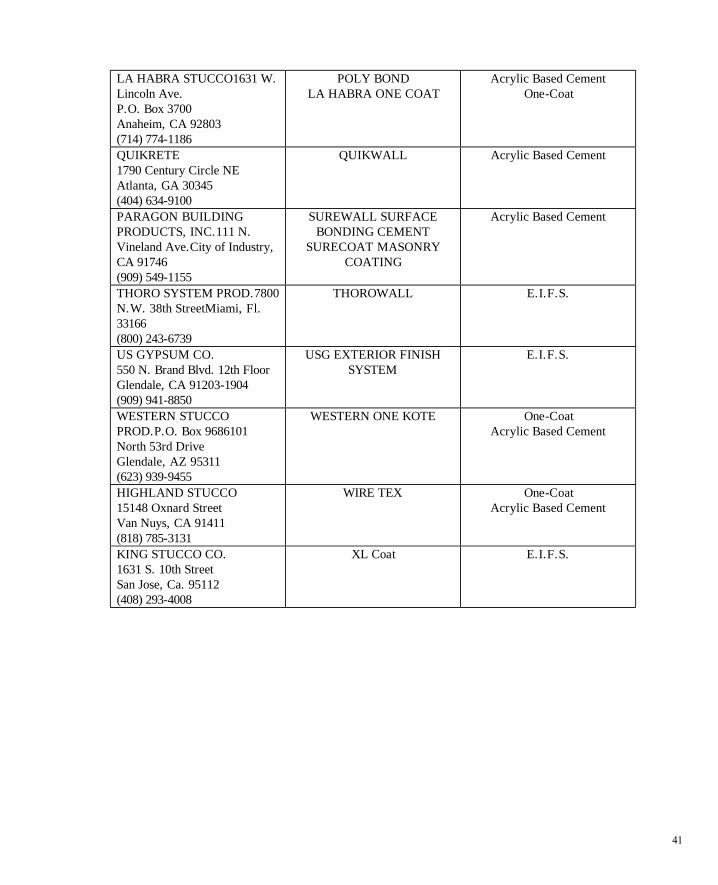
LA HABRA STUCCO1631 W. Lincoln Ave. P.O. Box 3700 Anaheim, CA 92803 (714) 774-1186
POLY BOND LA HABRA ONE COAT
Acrylic Based Cement One-Coat
QUIKRETE 1790 Century Circle NE Atlanta, GA 30345 (404) 634-9100
QUIKWALL Acrylic Based Cement
PARAGON BUILDING PRODUCTS, INC.111 N. Vineland Ave.City of Industry, CA 91746 (909) 549-1155
SUREWALL SURFACE BONDING CEMENT
SURECOAT MASONRY COATING
Acrylic Based Cement
THORO SYSTEM PROD.7800 N.W. 38th StreetMiami, Fl. 33166 (800) 243-6739
THOROWALL E.I.F.S.
US GYPSUM CO. 550 N. Brand Blvd. 12th Floor Glendale, CA 91203-1904 (909) 941-8850
USG EXTERIOR FINISH SYSTEM
E.I.F.S.
WESTERN STUCCO PROD.P.O. Box 9686101 North 53rd Drive Glendale, AZ 95311 (623) 939-9455
WESTERN ONE KOTE One-Coat Acrylic Based Cement
HIGHLAND STUCCO 15148 Oxnard Street Van Nuys, CA 91411 (818) 785-3131
WIRE TEX One-Coat Acrylic Based Cement
KING STUCCO CO. 1631 S. 10th Street San Jose, Ca. 95112 (408) 293-4008
XL Coat E.I.F.S.

42
6.3 Compatible Adhesive List--updated July 1999
NOTE: Any product that is certified by its manufacturer to be compatible with EPS, such as the products listed below, may be used with SmartBlock forms. American ConForm Industries makes no endorsement or guarantee for such products, or for the product listed below.
PRODUCT MANUFACTURER NOTES #77 Spray Adhesive 3M Corporation
(612) 736-3238 (800) 480-1704
Spray
ACE Construction Adhesive
ACE Hardware (800) 347-4583
Mastic
DAP 2000 Construction Adhesive
DAP Inc. 855 N. Third Street Dayton, OH (800) 543-3840
Mastic
Enerfoam Abisko Manufacturing, Inc.Richmond Hill, Ontario Canada, L4B 1E4 (800) 567-4447 ex. 43
Foam Adhesive System
Franklin Multi-Bond Solvent Free
Franklin International Bruck Street Columbus, OH (800) 877-4583 (614) 443-0241
Mastic
PL300 PL Premium
Chemrex, Inc. 889 Valley Park Drive Shakopee, MN 55379 (800) CHEMREX
Mastic
MD 200 Macklanberg-Duncan 4041 N. Santa Fe Oklahoma City, OK 73118 (800) 654-8454 (405) 528-4411
Mastic
Miracle DSA 40 Pratt & Lambert Specialty Prod.75 Tonawanda StreetBuffalo, NY 14207 (800) 876-7005
Mastic
This list is only a portion of the products you could use. If the material is not listed, check with the manufacturer for compatibility and installation instructions.


CHAPTER 7 Plumbing and Electrical
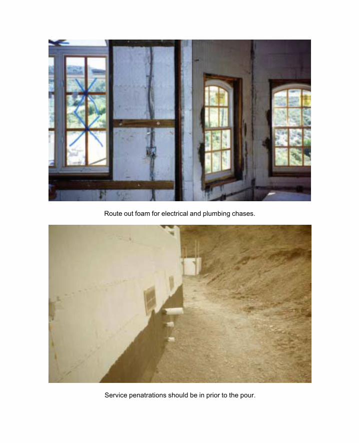
Route out foam for electrical and plumbing chases.
Service penatrations should be in prior to the pour.

43
Chapter 7 PLUMBING AND ELECTRICAL
7.1 Introduction to Plumbing and Electrical
Consideration of support services such as plumbing and electrical systems from the preliminary
schematics phase through final construction, including regard for ease of installation, cost and
future access requirements, can avoid many construction problems. Structural systems can be
modified and interior chases and soffits can be incorporated to provide space and access
necessary for years of satisfactory service. SmartBlock insulating form concrete walls share the
same attributes as other solid masonry wall systems and must incorporate many of the same
construction practices.
The following sections contain suggested methods to facilitate the installation of plumbing and
electrical systems in SmartBlock insulating form walls. All design parameters must obey the
rules of all applicable codes and regulations for all governing authorities having jurisdiction over
the project.
7.2 Plumbing
7.2.1 Direct Embedment
Design parameters for pipes in SmartBlock insulating form concrete walls are similar to the
design parameters for pipes in other solid masonry walls. Most building codes prohibit direct
embedment of pipes in concrete walls and foundations to avoid damage from expansion and
contraction of hot water pipes and from expansion, contraction and settlement of structural
systems.
44
7.2.2 Protection of Pipes
Code compliance through varying methods of protecting piping from the results of expansion,
freezing and structural stresses is generally interpretative. Suitability of any particular method
should be verified by local building officials during the design phase. Some methods now in use,
although legal in some jurisdictions, are not recommended by the manufacturer. Included, by
example, would be wrapping pipes in layers of building paper or any other method that would
restrict future access to that pipe. Some of these methods may be suitable for commercial
applications, but would be inappropriate in residential construction.
7.2.3 Installation Recommendations
The details in this manual should serve most conditions and are configured to show “extreme
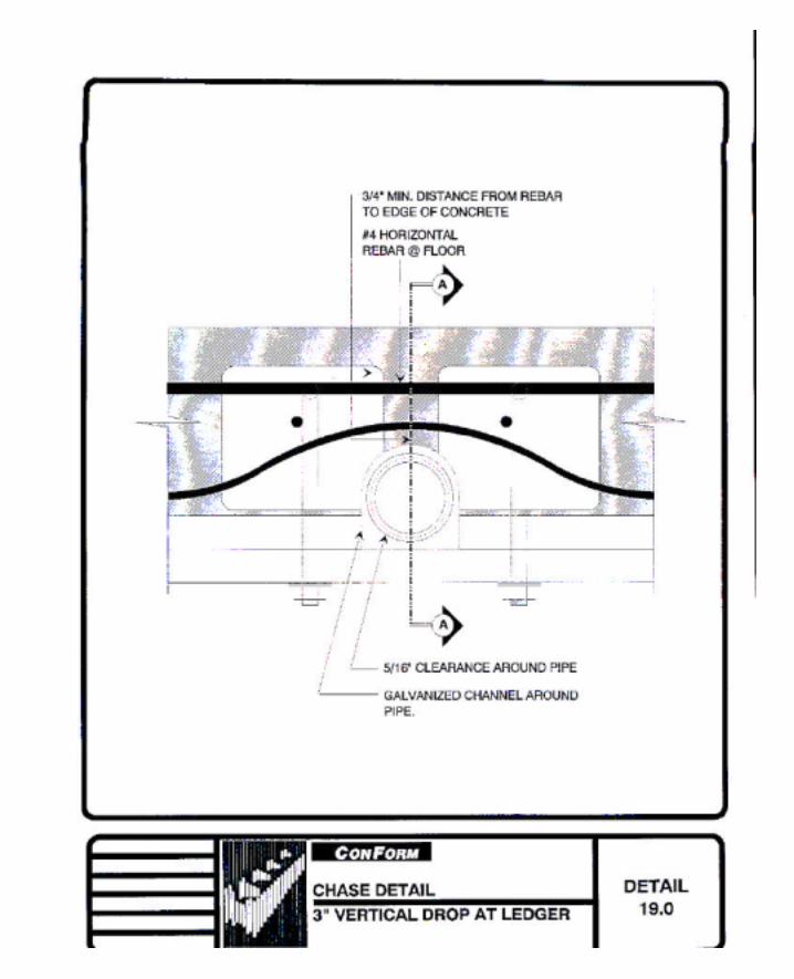
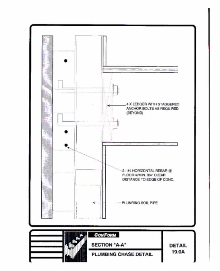
case” installation requirements. See Details 19.0 and 19.0A. “Extreme case” in this instance is
considered to be a 4” ABS soil line, running vertical past the floor ledger, assuming 5” across
the hub. Note: The use of 4” cast iron soil pipe may require the structural abandonment of an
entire vertical cell and specific engineering consideration would be necessary.
To embed pipes in SmartBlock SF10 Series walls, chases should be cut through the foam
blocks at the foam bridges. This method maintains the structural integrity of the vertical cell and
horizontal bond beam at the floor level. (This wall section should be shored until the concrete is
cured.) This location provides maximum concrete retention in the vertical cells and will not
affect the location of vertical reinforcing bars. The benefit of this system is that exact pipe
location is not necessary at the time of setting the vertical foundation reinforcing, as would be, if
an entire vertical cell were eliminated. When using this system for large pipe, a vertical section
of foam is removed to house a portion of the pipe. Since floor ledgers are inset into the foam
and secured directly to the concrete, vertical pipe runs conflict in this area. Ledgers may be
45
notched at this location, provided structural analysis has been performed as with any alteration
of structural support elements. Doubling the anchor bolts at either side of the notch should be
sufficient, although confirmation should be sought by the project architect or engineer.
Location of any structural reinforcing or fastening members in relation with the chase shall be
verified to meet all structural requirements as to clearances, embedment, continuous application,
etc.
Insulation of pipes in exterior walls may be required to protect pipes from freezing. The
remaining layer of polystyrene foam at the exterior may be sufficient to prevent freezing in milder
climates. Insulation of pipes may also be desired to dampen sound transmission. In most cases,
foam insulation fit onto the clearance space of the chase should be sufficient to reduce noise and
should not effect free movement of the pipe. These considerations should be addressed with
local building officials before application.
Installation of smaller pipes, including copper supply lines, may be channeled directly into the
foam. This is accomplished by using a router or heat tool to cut enough foam out providing a
channel of sufficient width and depth to house the pipe. When using this system, pipes must be
protected from mechanical damage. This may be accomplished by providing a section of metal
strap, no less than 1/16” thick, over the channel after the pipe is secured.
46
7.2.4 Support of Pipes
All pipes shall be supported as required by local codes, considering pipe alignment and the
weight of the piping and contents. Since pipes are to be installed after concrete is set, support
must be of an approved concrete fastening system.
Drilled concrete screw type anchors are recommended, although any approved concrete
fasteners may be used. Power actuated nails are not recommended with SmartBlock SF10
Series forms due to the possibility of firing pins through the foam bridges.
7.3 Electrical
Electrical wiring can easily be placed into walls built with SmartBlock insulating forms. Place
deep concrete junction boxes through the wall of the form at desired locations prior to pouring
concrete. This will allow for the mechanical attachment of the box to the concrete. Also prior
to pouring, run conduit to the primary junction boxes from the future location of the joist bay
above. The junction box will also serve as the switch location for the room’s “half hot” plug or
ceiling mounted fixture. Check with local building department for specific sizes and
requirements.
From the junction box, one Romex wire will be used for the switch and “half hot” plug; another
for the other electrical outlets required in the room. After the pour, these wires can be placed in
chases cut into the wall of the forms from the main junction box. Create a chase for the Romex
with a router or heat tool (a heat tool is faster, cleaner and more accurate) making larger cut
outs at the desired locations for the outlets. If holding a straight line is difficult with the router or
heat tool, snap a chalk line to follow a course.

47
To protect the Romex from nails or screws, a number of methods may be used. One method is
to cover the Romex with a minimum 16 gauge continuous “C” channel pressed flush with the
surface of the SmartBlock insulating form. As an alternative, if the foam is cut out to a minimum
of 1½”, the Romex can be glued in place with an adhesive or spray foam applied every 24” on
center. You can also replace the cut out foam piece over the Romex, pressing or rasping the
foam flush with the wall, so the Romex will not back out of the slot. Either method will give a
minimum 1½” protection, after addition of the drywall, to properly protect it from any
penetration.
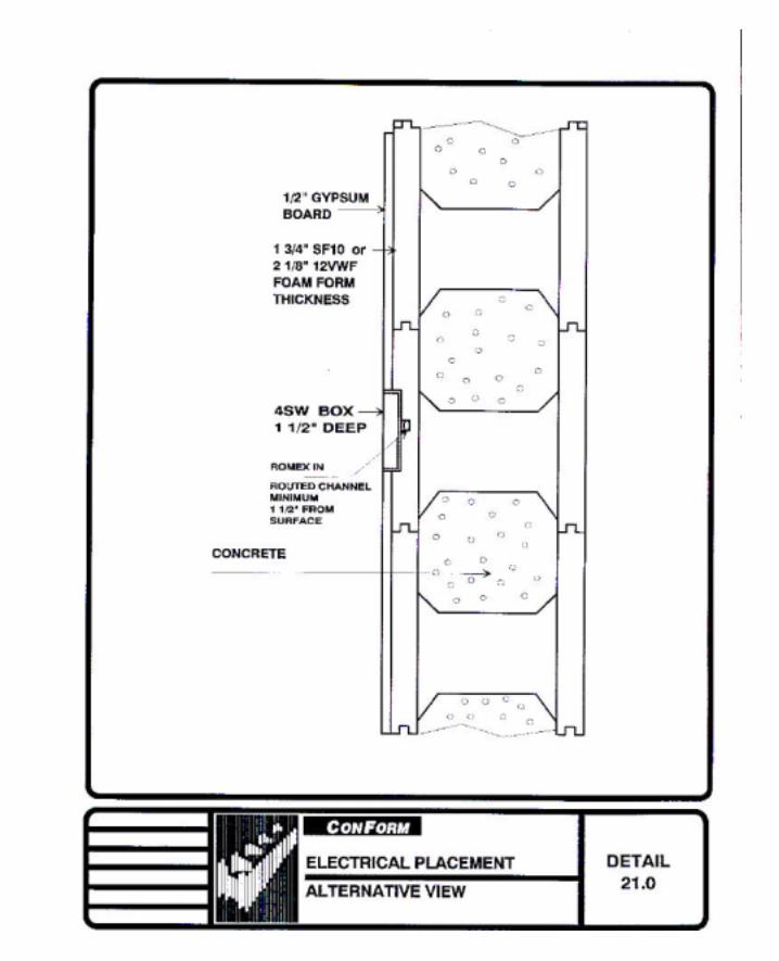
When using SF10 Series forms, locating outlet boxes on the bridges after concrete placement
will permit use of a deeper box. If boxes cannot be located on the bridges or if VWF Series
forms are installed, a shallow outlet will be required. See Detail 20.0 on page 88.


CHAPTER 8 Manufacturers Specifications
SmartBlock conforms to all building codes.
Angles or curves are easy with SmartBlock.
48
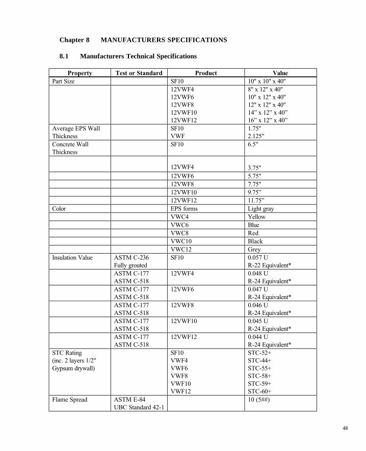
Chapter 8 MANUFACTURERS SPECIFICATIONS 8.1 Manufacturers Technical Specifications
Property Test or Standard Product Value Part Size SF10 10" x 10" x 40" 12VWF4
12VWF6 12VWF8 12VWF10 12VWF12
8" x 12" x 40" 10" x 12" x 40" 12" x 12" x 40" 14” x 12” x 40” 16” x 12” x 40”
Average EPS Wall Thickness
SF10 VWF
1.75" 2.125"
Concrete Wall Thickness
SF10 6.5"
12VWF4
3.75"
12VWF6 5.75" 12VWF8 7.75" 12VWF10 9.75” 12VWF12 11.75” Color EPS forms Light gray VWC4 Yellow VWC6 Blue VWC8 Red VWC10 Black VWC12 Grey Insulation Value ASTM C-236
Fully grouted SF10 0.057 U
R-22 Equivalent* ASTM C-177
ASTM C-518 12VWF4 0.048 U
R-24 Equivalent* ASTM C-177
ASTM C-518 12VWF6 0.047 U
R-24 Equivalent* ASTM C-177
ASTM C-518 12VWF8 0.046 U
R-24 Equivalent* ASTM C-177
ASTM C-518 12VWF10 0.045 U
R-24 Equivalent* ASTM C-177
ASTM C-518 12VWF12 0.044 U
R-24 Equivalent* STC Rating (inc. 2 layers 1/2" Gypsum drywall)
SF10 VWF4 VWF6 VWF8 VWF10 VWF12
STC-52+ STC-44+ STC-55+ STC-58+ STC-59+ STC-60+
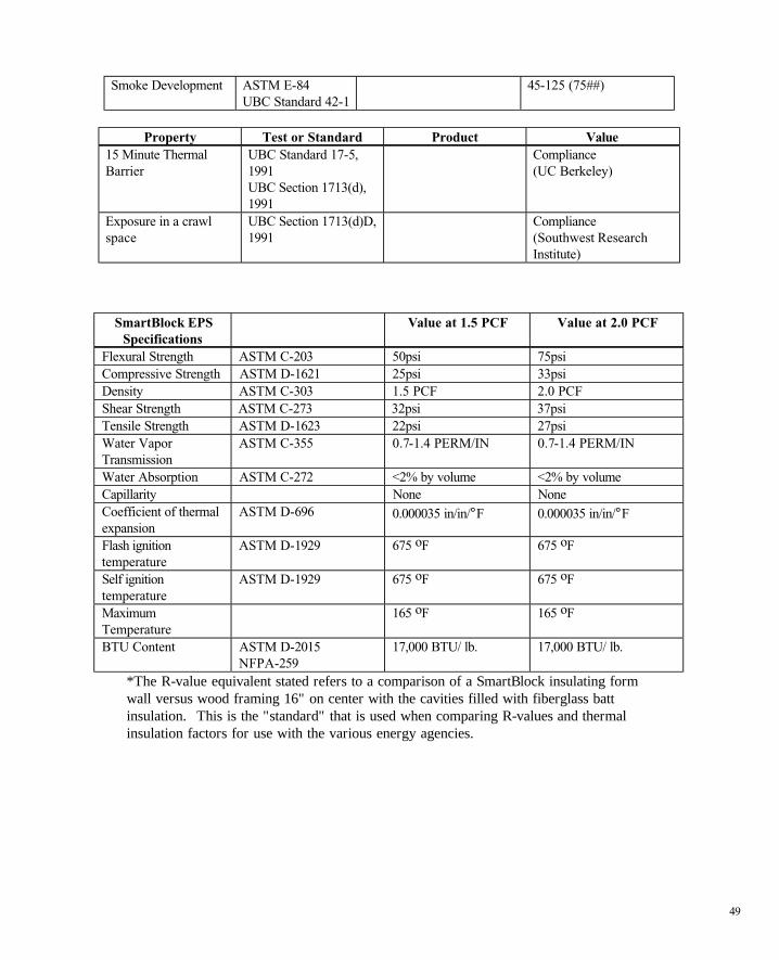
Flame Spread ASTM E-84 UBC Standard 42-1
10 (5##)
49
Smoke Development ASTM E-84 UBC Standard 42-1
45-125 (75##)
Property Test or Standard Product Value
15 Minute Thermal Barrier
UBC Standard 17-5, 1991 UBC Section 1713(d), 1991
Compliance (UC Berkeley)
Exposure in a crawl space
UBC Section 1713(d)D, 1991
Compliance (Southwest Research Institute)
SmartBlock EPS Specifications
Value at 1.5 PCF Value at 2.0 PCF
Flexural Strength ASTM C-203 50psi 75psi Compressive Strength ASTM D-1621 25psi 33psi Density ASTM C-303 1.5 PCF 2.0 PCF Shear Strength ASTM C-273 32psi 37psi Tensile Strength ASTM D-1623 22psi 27psi Water Vapor Transmission
ASTM C-355 0.7-1.4 PERM/IN 0.7-1.4 PERM/IN
Water Absorption ASTM C-272 <2% by volume <2% by volume Capillarity None None Coefficient of thermal expansion
ASTM D-696 0.000035 in/in/°F 0.000035 in/in/°F
Flash ignition temperature
ASTM D-1929 675 oF 675 oF
Self ignition temperature
ASTM D-1929 675 oF 675 oF
Maximum Temperature
165 oF 165 oF
BTU Content ASTM D-2015 NFPA-259
17,000 BTU/ lb. 17,000 BTU/ lb.
*The R-value equivalent stated refers to a comparison of a SmartBlock insulating form wall versus wood framing 16" on center with the cavities filled with fiberglass batt insulation. This is the "standard" that is used when comparing R-values and thermal insulation factors for use with the various energy agencies.
50
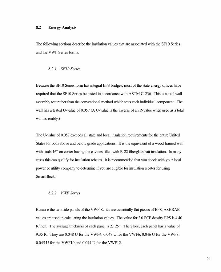
8.2 Energy Analysis
The following sections describe the insulation values that are associated with the SF10 Series
and the VWF Series forms.
8.2.1 SF10 Series
Because the SF10 Series form has integral EPS bridges, most of the state energy offices have
required that the SF10 Series be tested in accordance with ASTM C-236. This is a total wall
assembly test rather than the conventional method which tests each individual component. The
wall has a tested U-value of 0.057 (A U-value is the inverse of an R-value when used as a total
wall assembly.)
The U-value of 0.057 exceeds all state and local insulation requirements for the entire United
States for both above and below grade applications. It is the equivalent of a wood framed wall
with studs 16” on center having the cavities filled with R-22 fiberglass batt insulation. In many
cases this can qualify for insulation rebates. It is recommended that you check with your local
power or utility company to determine if you are eligible for insulation rebates for using
SmartBlock.
8.2.2 VWF Series
Because the two side panels of the VWF Series are essentially flat pieces of EPS, ASHRAE
values are used in calculating the insulation values. The value for 2.0 PCF density EPS is 4.40
R/inch. The average thickness of each panel is 2.125”. Therefore, each panel has a value of
9.35 R. They are 0.048 U for the VWF4, 0.047 U for the VWF6, 0.046 U for the VWF8,
0.045 U for the VWF10 and 0.044 U for the VWF12.
51
The U-values of 0.048, 0.047, 0.046, 0.045 and 0.044 exceed all state and local insulation
requirements for the entire United States for both above and below grade applications. These
values are the equivalent of a wood framed wall with studs 16” on center having the cavities
filled with R-24 fiberglass batt insulation. In many cases this can qualify for insulation rebates.
It is recommended that you check with your local power or utility company to determine if you
are eligible for insulation rebates for over insulating your structure.
52
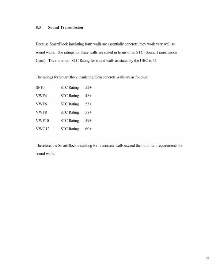
8.3 Sound Transmission
Because SmartBlock insulating form walls are essentially concrete, they work very well as
sound walls. The ratings for these walls are stated in terms of an STC (Sound Transmission
Class). The minimum STC Rating for sound walls as stated by the UBC is 45.
The ratings for SmartBlock insulating form concrete walls are as follows:
SF10 STC Rating 52+
VWF4 STC Rating 48+
VWF6 STC Rating 55+
VWF8 STC Rating 58+
VWF10 STC Rating 59+
VWC12 STC Rating 60+
Therefore, the SmartBlock insulating form concrete walls exceed the minimum requirements for
sound walls.
53
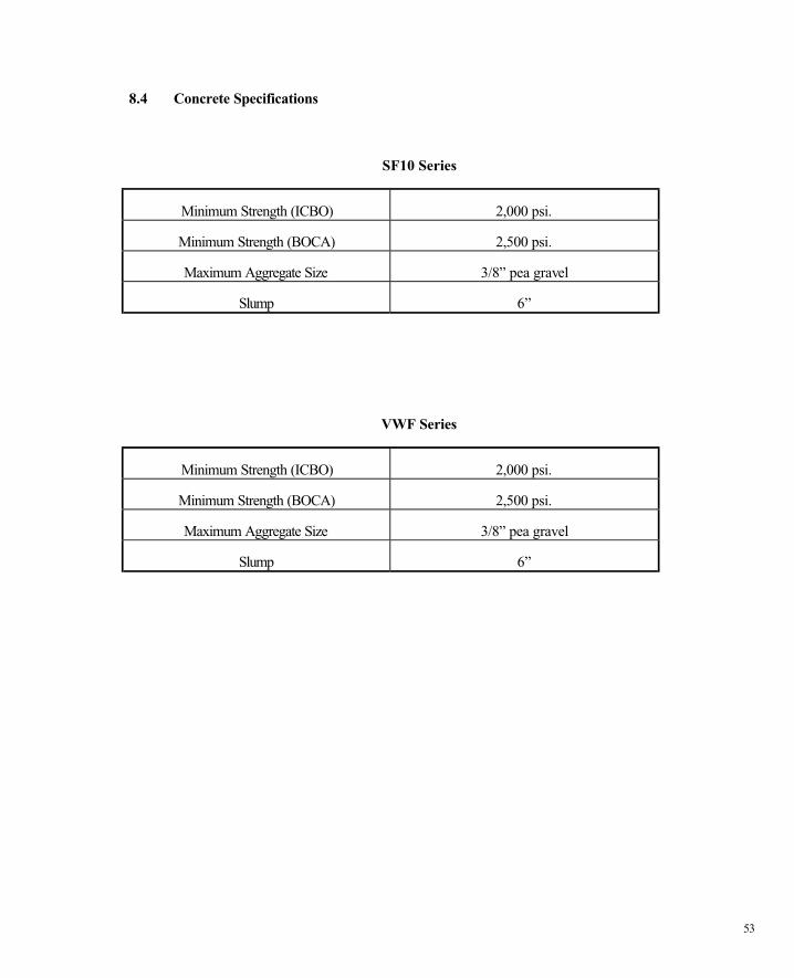
8.4 Concrete Specifications
SF10 Series
Minimum Strength (ICBO) 2,000 psi.
Minimum Strength (BOCA) 2,500 psi.
Maximum Aggregate Size 3/8” pea gravel
Slump 6”
VWF Series
Minimum Strength (ICBO) 2,000 psi.
Minimum Strength (BOCA) 2,500 psi.
Maximum Aggregate Size 3/8” pea gravel
Slump 6”
54
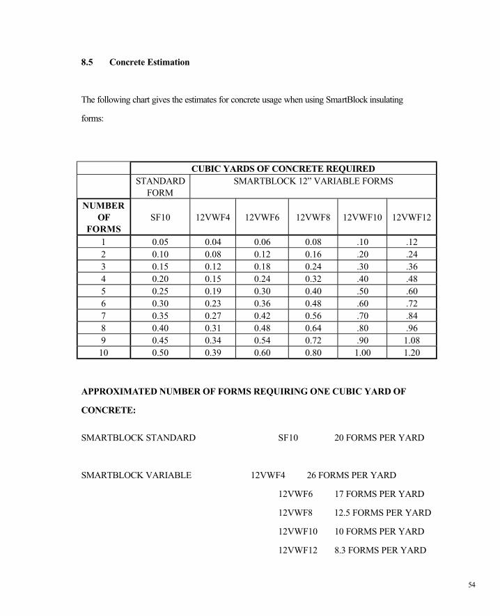
8.5 Concrete Estimation
The following chart gives the estimates for concrete usage when using SmartBlock insulating
forms:
CUBIC YARDS OF CONCRETE REQUIRED STANDARD
FORM SMARTBLOCK 12” VARIABLE FORMS
NUMBER
OF FORMS
SF10
12VWF4
12VWF6
12VWF8
12VWF10
12VWF12
1 0.05 0.04 0.06 0.08 .10 .12 2 0.10 0.08 0.12 0.16 .20 .24 3 0.15 0.12 0.18 0.24 .30 .36 4 0.20 0.15 0.24 0.32 .40 .48 5 0.25 0.19 0.30 0.40 .50 .60 6 0.30 0.23 0.36 0.48 .60 .72 7 0.35 0.27 0.42 0.56 .70 .84 8 0.40 0.31 0.48 0.64 .80 .96 9 0.45 0.34 0.54 0.72 .90 1.08
10 0.50 0.39 0.60 0.80 1.00 1.20
APPROXIMATED NUMBER OF FORMS REQUIRING ONE CUBIC YARD OF
CONCRETE:
SMARTBLOCK STANDARD SF10 20 FORMS PER YARD
SMARTBLOCK VARIABLE 12VWF4 26 FORMS PER YARD
12VWF6 17 FORMS PER YARD
12VWF8 12.5 FORMS PER YARD
12VWF10 10 FORMS PER YARD
12VWF12 8.3 FORMS PER YARD
55
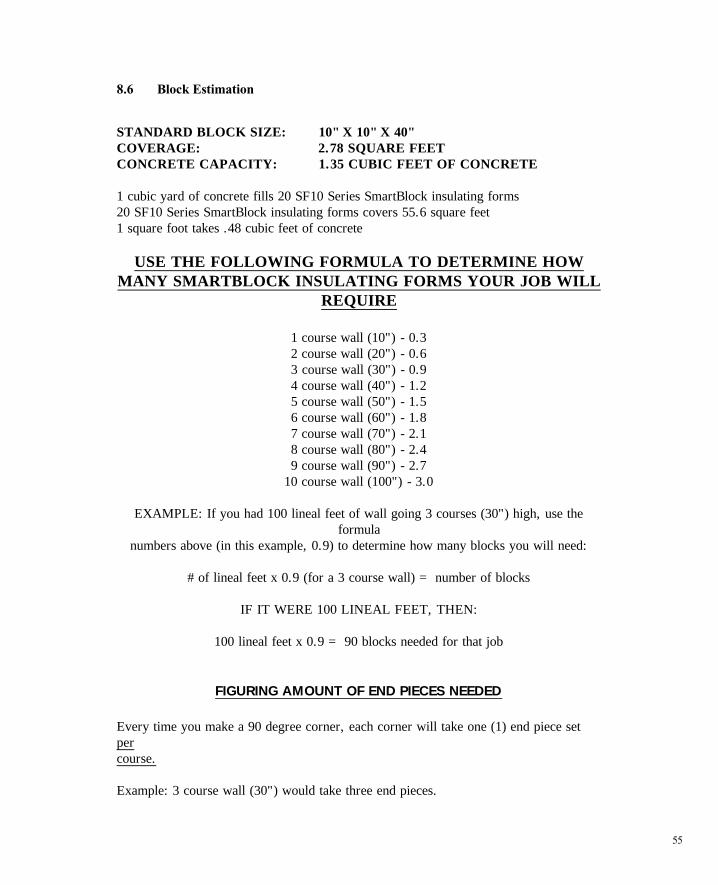
8.6 Block Estimation
STANDARD BLOCK SIZE: 10" X 10" X 40" COVERAGE: 2.78 SQUARE FEET CONCRETE CAPACITY: 1.35 CUBIC FEET OF CONCRETE 1 cubic yard of concrete fills 20 SF10 Series SmartBlock insulating forms 20 SF10 Series SmartBlock insulating forms covers 55.6 square feet 1 square foot takes .48 cubic feet of concrete
USE THE FOLLOWING FORMULA TO DETERMINE HOW MANY SMARTBLOCK INSULATING FORMS YOUR JOB WILL
REQUIRE
1 course wall (10") - 0.3 2 course wall (20") - 0.6 3 course wall (30") - 0.9 4 course wall (40") - 1.2 5 course wall (50") - 1.5 6 course wall (60") - 1.8 7 course wall (70") - 2.1 8 course wall (80") - 2.4 9 course wall (90") - 2.7
10 course wall (100") - 3.0
EXAMPLE: If you had 100 lineal feet of wall going 3 courses (30") high, use the formula
numbers above (in this example, 0.9) to determine how many blocks you will need:
# of lineal feet x 0.9 (for a 3 course wall) = number of blocks
IF IT WERE 100 LINEAL FEET, THEN:
100 lineal feet x 0.9 = 90 blocks needed for that job
FIGURING AMOUNT OF END PIECES NEEDED
Every time you make a 90 degree corner, each corner will take one (1) end piece set per course. Example: 3 course wall (30") would take three end pieces.
56
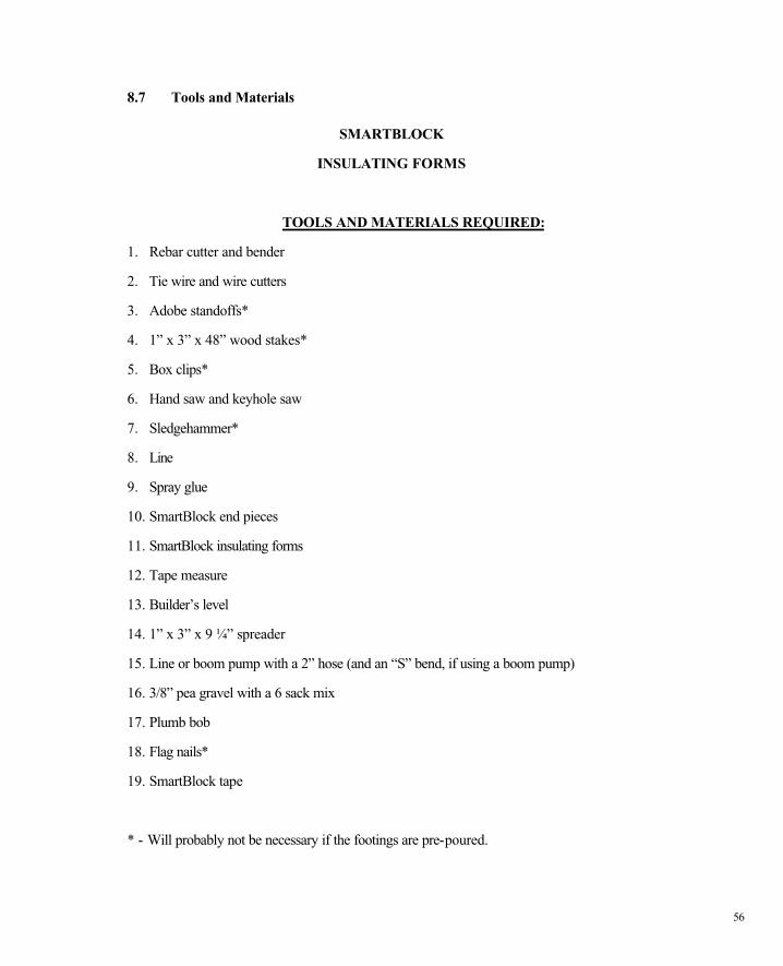
8.7 Tools and Materials
SMARTBLOCK
INSULATING FORMS
TOOLS AND MATERIALS REQUIRED:
1. Rebar cutter and bender
2. Tie wire and wire cutters
3. Adobe standoffs*
4. 1” x 3” x 48” wood stakes*
5. Box clips*
6. Hand saw and keyhole saw
7. Sledgehammer*
8. Line
9. Spray glue
10. SmartBlock end pieces
11. SmartBlock insulating forms
12. Tape measure
13. Builder’s level
14. 1” x 3” x 9 ¼” spreader
15. Line or boom pump with a 2” hose (and an “S” bend, if using a boom pump)
16. 3/8” pea gravel with a 6 sack mix
17. Plumb bob
18. Flag nails*
19. SmartBlock tape
* - Will probably not be necessary if the footings are pre-poured.
57
8.8 Radius Cut Outs
SmartBlock insulating form walls are easily manipulated to produce radiused and curved walls.
By cutting out portions of the interior cell, between the bridges, a curved wall can be formed.
For inside radius cuts, the formula for determining the amount of area to cut out of each cell is as
follows:
Cut out per cell in inches = block width x cell length (in inches)
radius (inside) + block width (in inches)
For outside radius cuts, the formula is as follows:
Cut out per cell inches = block width x cell length (in inches)
radius (outside)
It is important to remember that each block will have four cuts and that all cuts must
be the same in order to achieve a smooth curved wall appearance.
The chart on the following page contains cut out dimensions (in inches) per cell based on
commonly used radius amounts:
58
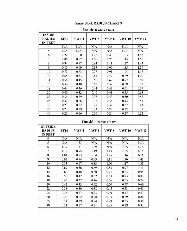
SmartBlock RADIUS CHARTS
Inside Radius Chart INSIDE RADIUS IN FEET
SF10
VWF 4
VWF 6
VWF 8
VWF 10
VWF 12
4 N/A N/A N/A N/A N/A N/A 5 N/A N/A N/A N/A N/A N/A 6 1.22 1.00 1.22 1.43 1.63 1.82 7 1.06 0.87 1.06 1.25 1.43 1.60 8 0.94 0.77 0.94 1.11 1.27 1.43 9 0.85 0.69 0.85 1.00 1.15 1.29
10 0.77 0.63 0.77 0.91 1.04 1.18 12 0.65 0.53 0.65 0.77 0.89 1.00 14 0.56 0.45 0.56 0.67 0.77 0.87 16 0.50 0.40 0.50 0.59 0.68 0.77 18 0.44 0.36 0.44 0.53 0.61 0.69 20 0.40 0.32 0.40 0.48 0.55 0.63 22 0.36 0.29 0.36 0.43 0.50 0.57 25 0.32 0.26 0.32 0.38 0.44 0.51 30 0.27 0.22 0.27 0.32 0.37 0.43 35 0.23 0.19 0.23 0.28 0.32 0.37 40 0.20 0.16 0.20 0.24 0.28 0.32
Outside Radius Chart OUTSIDE RADIUS IN FEET
SF10
VWF 4
VWF 6
VWF 8
VWF 10
VWF 12
4 N/A N/A N/A N/A N/A N/A 5 N/A 1.33 N/A N/A N/A N/A 6 1.39 1.11 1.39 N/A N/A N/A 7 1.19 0.95 1.19 1.43 N/A N/A 8 1.04 0.93 1.04 1.25 1.46 N/A 9 0.93 0.74 0.93 1.11 1.30 1.48 10 0.83 0.67 0.83 1.00 1.17 1.33 12 0.69 0.56 0.69 0.83 0.97 1.11 14 0.60 0.48 0.60 0.71 0.83 0.95 16 0.52 0.42 0.52 0.63 0.73 0.83 18 0.46 0.37 0.46 0.56 0.65 0.74 20 0.42 0.33 0.42 0.50 0.58 0.66 22 0.38 0.30 0.38 0.45 0.53 0.61 25 0.33 0.27 0.33 0.40 0.47 0.53 30 0.28 0.22 0.28 0.33 0.39 0.44 35 0.24 0.19 0.24 0.29 0.33 0.38 40 0.21 0.17 0.21 0.25 0.29 0.33

CHAPTER 9 Design Details
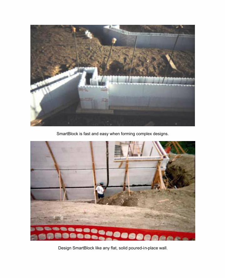
SmartBlock is fast and easy when forming complex designs.
Design SmartBlock like any flat, solid poured-in-place wall.
59
Chapter 9 DESIGN DETAILS
The following chapter contains drawings, design details, and charts for recommended use with
SmartBlock insulating forms. These drawings, design details, and charts are based upon
generally approved design and engineering techniques and are intended as guides only.
Because specific conditions may vary, architects, engineers, and local building officials should be
consulted for proper application in all SmartBlock insulating form projects.

60
9.1 Design Section
61
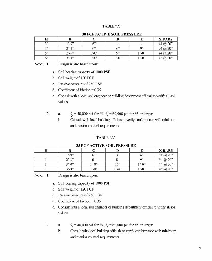
TABLE “A”
30 PCF ACTIVE SOIL PRESSURE H B C D E X BARS 3’ 1’-9” 6” - - #4 @ 20” 4’ 2’-2” 6” 6” 9” #4 @ 20” 5’ 2’-9” 1’-0” 9” 1’-0” #4 @ 20” 6’ 3’-4” 1’-0” 1’-0” 1’-0” #5 @ 20”
Note: 1. Design is also based upon:
a. Soil bearing capacity of 1000 PSF
b. Soil weight of 120 PCF
c. Passive pressure of 250 PSF
d. Coefficient of friction = 0.35
e. Consult with a local soil engineer or building department official to verify all soil
values.
2. a. fy = 40,000 psi for #4; fy = 60,000 psi for #5 or larger
b. Consult with local building officials to verify conformance with minimum
and maximum steel requirements.
TABLE “A”
35 PCF ACTIVE SOIL PRESSURE H B C D E X BARS 3’ 1’-9” 6” 3” 6” #4 @ 20” 4’ 2’-3” 6” 8” 9” #4 @ 20” 5’ 3’-0” 1’-0” 10” 1’-0” #4 @ 20” 6’ 3’-8” 1’-0” 1’-4” 1’-0” #5 @ 20”
Note: 1. Design is also based upon:
a. Soil bearing capacity of 1000 PSF
b. Soil weight of 120 PCF
c. Passive pressure of 250 PSF
d. Coefficient of friction = 0.35
e. Consult with a local soil engineer or building department official to verify all soil
values.
2. a. fy = 40,000 psi for #4; fy = 60,000 psi for #5 or larger
b. Consult with local building officials to verify conformance with minimum
and maximum steel requirements.
62
TABLE “A” 40 PCF ACTIVE SOIL PRESSURE
H B C D E X BARS 3’ 1’-1-“ 6” 4” 6” #4 @ 20” 4’ 2’-6” 6” 10” 9” #4 @ 20” 5’ 3’-2” 1’-0” 1’-2” 1’-0” #4 @ 20” 6’ 3’-10” 1’-0” 1’-7” 1’-0” #5 @ 20”
Note: 1. Design is also based upon:
a. Soil bearing capacity of 1000 PSF b. Soil weight of 120 PCF c. Passive pressure of 250 PSF d. Coefficient of friction = 0.35 e. Consult with a local soil engineer or building department official to verify all
soil values. 2. a. fy = 40,000 psi for #4; fy = 60,000 psi for #5 or larger b. Consult with local building officials to verify conformance with minimum
and maximum steel requirements.
TABLE “A” 45 PCF ACTIVE SOIL PRESSURE
H B C D E X BARS 3’ 2’-0” 6” 6” 6” #4 @ 20” 4’ 2’-8” 6” 1’-0” 9” #4 @ 20” 5’ 3’-6” 1’-0” 1’-4” 1’-0” #4 @ 20” 6’ 4’-0” 1’-0” 1’-10” 1’-6” #5 @ 20”
Note: 1. Design is also based upon:
a. Soil bearing capacity of 1000 PSF b. Soil weight of 120 PCF c. Passive pressure of 250 PSF d. Coefficient of friction = 0.35 e. Consult with a local soil engineer or building department official to verify all
soil values. 2. a. fy = 40,000 psi for #4; fy = 60,000 psi for #5 or larger b. Consult with local building officials to verify conformance with minimum
and maximum steel requirements.

63
TABLE “A” 50 PCF ACTIVE SOIL PRESSURE
H B C D E X BARS 3’ 2’-2” 6” 9” 6” #4 @ 20” 4’ 2’9” 6” 1’-2” 9” #4 @ 20” 5’ 3’-6” 1’-0” 1’-6” 1’-0” #5 @ 20” 6’ 4’-3” 1’-0” 2”-0” 1’-6” #5 @ 20”
Note: 1. Design is also based upon:
a. Soil bearing capacity of 1000 PSF b. Soil weight of 120 PCF c. Passive pressure of 250 PSF d. Coefficient of friction = 0.35 e. Consult with a local soil engineer or building department official to verify all soil
values. 2. a. fy = 40,000 psi for #4; fy = 60,000 psi for #5 or larger b. Consult with local building officials to verify conformance with minimum
and maximum steel requirements.
TABLE “A” 55 PCF ACTIVE SOIL PRESSURE
H B C D E X BARS 3’ 2’-2” 6” 9” 6” #4 @ 20” 4’ 2’-11” 6” 1’-3” 9” #4 @ 20” 5’ 3’-8” 1’-0” 1’-8” 1’-6” #5 @ 20” 6’ 4’-6” 1’-0” 2’-3” 1’-9” #5 @ 20”
Note: 1. Design is also based upon:
a. Soil bearing capacity of 1000 PSF b. Soil weight of 120 PCF c. Passive pressure of 250 PSF d. Coefficient of friction = 0.35 e. Consult with a local soil engineer or building department official to verify all soil
values. 2. a. fy = 40,000 psi for #4; fy = 60,000 psi for #5 or larger b. Consult with local building officials to verify conformance with minimum
and maximum steel requirements.

64
TABLE “A” 60 PCF ACTIVE SOIL PRESSURE
H B C D E X BARS 3’ 2’-3” 6” 10” 6” #4 @ 20” 4’ 3’-2” 6” 1’-5” 1’-0” #4 @ 20” 5’ 3’-10” 1’-0” 1’-10” 1’-6” #5 @ 20” 6’ 4’-8” 1’-0” 2’-5” 2’-0” #5 @ 10”
Note: 1. Design is also based upon:
a. Soil bearing capacity of 1000 PSF b. Soil weight of 120 PCF c. Passive pressure of 250 PSF d. Coefficient of friction = 0.35 e. Consult with a local soil engineer or building department official to verify all soil
values. 2. a. fy = 40,000 psi for #4; fy = 60,000 psi for #5 or larger b. Consult with local building officials to verify conformance with minimum
and maximum steel requirements.
TABLE “A”
65 PCF ACTIVE SOIL PRESSURE H B C D E X BARS 3’ 2’-3” 6” 1’-0” 9” #4 @ 20” 4’ 3’-1” 6” 1’-6” 1’-3” #4 @ 20” 5’ 3’-11” 1’-0” 2’-0” 1’-6” #5 @ 20” 6’ 4’-9” 1’-0” 2’-7” 2’-0” #5 @ 10”
Note: 1. Design is also based upon:
a. Soil bearing capacity of 1000 PSF b. Soil weight of 120 PCF c. Passive pressure of 250 PSF d. Coefficient of friction = 0.35 e. Consult with a local soil engineer or building department official to verify all
soil values. 2. a. fy = 40,000 psi for #4; fy = 60,000 psi for #5 or larger b. Consult with local building officials to verify conformance with minimum
and maximum steel requirements.
65
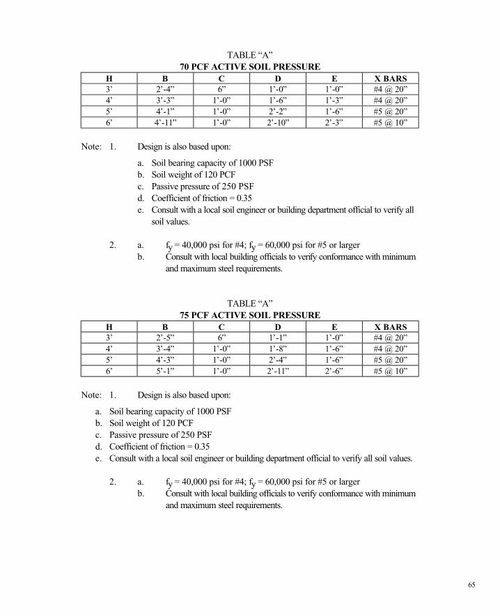
TABLE “A” 70 PCF ACTIVE SOIL PRESSURE
H B C D E X BARS 3’ 2’-4” 6” 1’-0” 1’-0” #4 @ 20” 4’ 3’-3” 1’-0” 1’-6” 1’-3” #4 @ 20” 5’ 4’-1” 1’-0” 2’-2” 1’-6” #5 @ 20” 6’ 4’-11” 1’-0” 2’-10” 2’-3” #5 @ 10”
Note: 1. Design is also based upon:
a. Soil bearing capacity of 1000 PSF b. Soil weight of 120 PCF c. Passive pressure of 250 PSF d. Coefficient of friction = 0.35 e. Consult with a local soil engineer or building department official to verify all
soil values. 2. a. fy = 40,000 psi for #4; fy = 60,000 psi for #5 or larger b. Consult with local building officials to verify conformance with minimum
and maximum steel requirements.
TABLE “A”
75 PCF ACTIVE SOIL PRESSURE H B C D E X BARS 3’ 2’-5” 6” 1’-1” 1’-0” #4 @ 20” 4’ 3’-4” 1’-0” 1’-8” 1’-6” #4 @ 20” 5’ 4’-3” 1’-0” 2’-4” 1’-6” #5 @ 20” 6’ 5’-1” 1’-0” 2’-11” 2’-6” #5 @ 10”
Note: 1. Design is also based upon:
a. Soil bearing capacity of 1000 PSF b. Soil weight of 120 PCF c. Passive pressure of 250 PSF d. Coefficient of friction = 0.35 e. Consult with a local soil engineer or building department official to verify all soil values.
2. a. fy = 40,000 psi for #4; fy = 60,000 psi for #5 or larger b. Consult with local building officials to verify conformance with minimum
and maximum steel requirements.
66
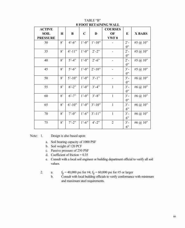
TABLE “B” 8 FOOT RETAINING WALL
ACTIVE SOIL
PRESSURE
H
B
C
D
COURSES OF
VWF 8
E
X BARS
30 8’ 4’-6” 1’-0” 1’-10” - 2’-0”
#5 @ 10”
35 8’ 4’-11” 1’-0” 2’-2” - 2’-0”
#5 @ 10”
40 8’ 5’-4” 1’-0” 2’-6” - 2’-0”
#5 @ 10”
45 8’ 5’-6” 1’-0” 2’-10” - 3’-0”
#5 @ 10”
50 8’ 5’-10” 1’-0” 3’-1” - 3’-0”
#6 @ 10”
55 8’ 6’-2” 1’-0” 3’-4” 1 3’-0”
#6 @ 10”
60 8’ 6’-7” 1’-0” 3’-8” 1 3’-0”
#6 @ 10”
65 8’ 6’-10” 1’-0” 3’-10” 1 3’-6”
#6 @ 10”
70 8’ 7’-0” 1’-6” 3’-11” 1 3’-6”
#6 @ 10”
75 8’ 7’-2” 1’-6” 4’-2” 2 3’-6”
#6 @ 10”
Note: 1. Design is also based upon:
a. Soil bearing capacity of 1000 PSF b. Soil weight of 120 PCF c. Passive pressure of 250 PSF d. Coefficient of friction = 0.35 e. Consult with a local soil engineer or building department official to verify all soil
values. 2. a. fy = 40,000 psi for #4; fy = 60,000 psi for #5 or larger b. Consult with local building officials to verify conformance with minimum
and maximum steel requirements.
67
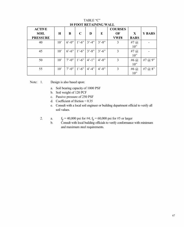
TABLE “C” 10 FOOT RETAINING WALL
ACTIVE SOIL
PRESSURE
H
B
C
D
E
COURSES OF
VWF8
X
BARS
Y BARS
40 10’ 6’-0” 1’-6” 3’-4” 3’-0” 3 #7 @ 10”
-
45 10’ 6’-6” 1’-6” 3’-8” 3’-6” 3 #7 @ 10”
-
50 10’ 7’-0” 1’-6” 4’-1” 4’-0” 3 #6 @ 10”
#7 @ 9”
55 10’ 7’-0” 1’-6” 4’-4” 4’-0” 3 #6 @ 10”
#7 @ 8”
Note: 1. Design is also based upon:
a. Soil bearing capacity of 1000 PSF b. Soil weight of 120 PCF c. Passive pressure of 250 PSF d. Coefficient of friction = 0.35 e. Consult with a local soil engineer or building department official to verify all
soil values. 2. a. fy = 40,000 psi for #4; fy = 60,000 psi for #5 or larger b. Consult with local building officials to verify conformance with minimum
and maximum steel requirements.
68
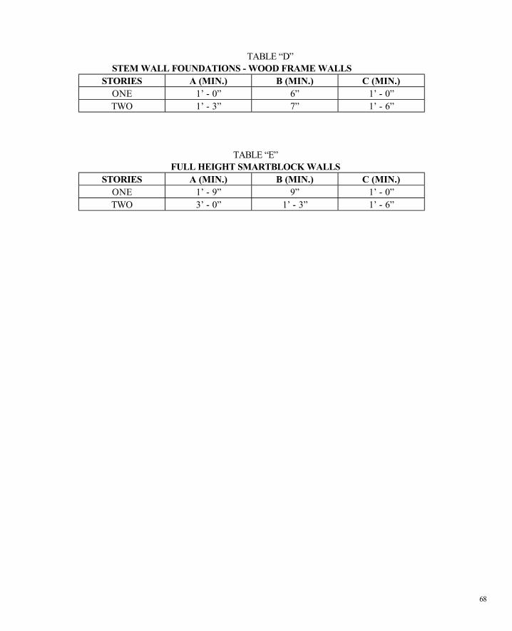
TABLE “D” STEM WALL FOUNDATIONS - WOOD FRAME WALLS
STORIES A (MIN.) B (MIN.) C (MIN.) ONE 1’ - 0” 6” 1’ - 0” TWO 1’ - 3” 7” 1’ - 6”
TABLE “E” FULL HEIGHT SMARTBLOCK WALLS
STORIES A (MIN.) B (MIN.) C (MIN.) ONE 1’ - 9” 9” 1’ - 0” TWO 3’ - 0” 1’ - 3” 1’ - 6”

69
9.2 Detail Section


9.3 Micellaneous Details


CHAPTER 10 Support Reports
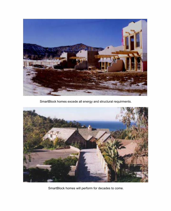
SmartBlock homes excede all energy and structural requirments.
SmartBlock homes will perform for decades to come.
Page 1 of 10
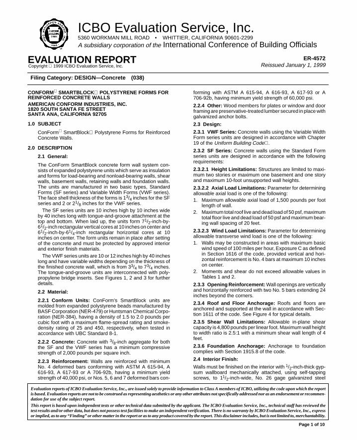
ICBO Evaluation Service, Inc.5360 WORKMAN MILL ROAD • WHITTIER, CALIFORNIA 90601-2299
A subsidiary corporation of the International Conference of Building Officials
EVALUATION REPORTCopyright 1999 ICBO Evaluation Service, Inc.
ER-4572Reissued January 1, 1999
Filing Category: DESIGN—Concrete (038)
CONFORM SMARTBLOCK POLYSTYRENE FORMS FORREINFORCED CONCRETE WALLSAMERICAN CONFORM INDUSTRIES, INC.1820 SOUTH SANTA FE STREETSANTA ANA, CALIFORNIA 92705
1.0 SUBJECT
ConForm SmartBlock Polystyrene Forms for ReinforcedConcrete Walls.
2.0 DESCRIPTION
2.1 General:
The ConForm SmartBlock concrete form wall system con-sists of expanded polystyrene units which serve as insulationand forms for load-bearing and nonload-bearing walls, shearwalls, basement walls, retaining walls and foundation walls.The units are manufactured in two basic types, StandardForms (SF series) and Variable Width Forms (VWF series).The face shell thickness of the forms is 13/4 inches for the SFseries and 2 or 21/8 inches for the VWF series.
The SF series units are 10 inches high by 10 inches wideby 40 inches long with tongue-and-groove attachment at thetop and bottom. When laid up, the units form 71/2-inch-by-61/2-inch rectangular vertical cores at 10 inches on center and61/2-inch-by-61/4-inch rectangular horizontal cores at 10inches on center. The form units remain in place after settingof the concrete and must be protected by approved interiorand exterior finish materials.
The VWF series units are 10 or 12 inches high by 40 incheslong and have variable widths depending on the thickness ofthe finished concrete wall, which is from 33/4 to 73/4 inches.The tongue-and-groove units are interconnected with poly-propylene bridge inserts. See Figures 1, 2 and 3 for furtherdetails.
2.2 Material:
2.2.1 Conform Units: ConForm’s SmartBlock units aremolded from expanded polystyrene beads manufactured byBASF Corporation (NER-479) or Huntsman Chemical Corpo-ration (NER-384), having a density of 1.5 to 2.0 pounds percubic foot with a maximum flame-spread rating and smoke-density rating of 25 and 450, respectively, when tested inaccordance with UBC Standard 8-1.
2.2.2 Concrete: Concrete with 3/8-inch aggregate for boththe SF and the VWF series has a minimum compressivestrength of 2,000 pounds per square inch.
2.2.3 Reinforcement: Walls are reinforced with minimumNo. 4 deformed bars conforming with ASTM A 615-94, A616-93, A 617-93 or A 706-92b, having a minimum yieldstrength of 40,000 psi, or Nos. 5, 6 and 7 deformed bars con-
forming with ASTM A 615-94, A 616-93, A 617-93 or A706-92b, having minimum yield strength of 60,000 psi.
2.2.4 Other: Wood members for plates or window and doorframing are preservative-treated lumber secured in place withgalvanized anchor bolts.
2.3 Design:
2.3.1 VWF Series: Concrete walls using the Variable WidthForm series units are designed in accordance with Chapter19 of the Uniform Building Code .
2.3.2 SF Series: Concrete walls using the Standard Formseries units are designed in accordance with the followingrequirements:
2.3.2.1 Height Limitations: Structures are limited to maxi-mum two stories or maximum one basement and one storyand maximum 10-foot unsupported wall heights.
2.3.2.2 Axial Load Limitations: Parameter for determiningallowable axial load is one of the following:1. Maximum allowable axial load of 1,500 pounds per foot
length of wall.2. Maximum total roof live and dead load of 50 psf, maximum
total floor live and dead load of 50 psf and maximum bear-ing wall spacing of 20 feet.
2.3.2.3 Wind Load Limitations: Parameter for determiningallowable transverse wind load is one of the following:1. Walls may be constructed in areas with maximum basic
wind speed of 100 miles per hour, Exposure C as definedin Section 1616 of the code, provided vertical and hori-zontal reinforcement is No. 4 bars at maximum 10 incheson center.
2. Moments and shear do not exceed allowable values inTables 1 and 2.
2.3.3 Opening Reinforcement: Wall openings are verticallyand horizontally reinforced with two No. 5 bars extending 24inches beyond the corners.
2.3.4 Roof and Floor Anchorage: Roofs and floors areanchored and supported at the wall in accordance with Sec-tion 1611 of the code. See Figure 4 for typical details.
2.3.5 Shear Wall Limitations: Allowable in-plane shearcapacity is 4,800 pounds per linear foot. Maximum wall heightto width ratio is 2.5:1 with a minimum shear wall length of 4feet.
2.3.6 Foundation Anchorage: Anchorage to foundationcomplies with Section 1915.8 of the code.
2.4 Interior Finish:
Walls must be finished on the interior with 1/2-inch-thick gyp-sum wallboard mechanically attached, using self-tappingscrews, to 11/2-inch-wide, No. 26 gage galvanized steel
Evaluation reports of ICBO Evaluation Service, Inc., are issued solely to provide information to Class A members of ICBO, utilizing the code upon which the reportis based. Evaluation reports are not to be construed as representing aesthetics or any other attributes not specifically addressed nor as an endorsement or recommen-dation for use of the subject report.
This report is based upon independent tests or other technical data submitted by the applicant. The ICBO Evaluation Service, Inc., technical staff has reviewed thetest results and/or other data, but does not possess test facilities to make an independent verification. There is no warranty by ICBO Evaluation Service, Inc., expressor implied, as to any “Finding” or other matter in the report or as to any product covered by the report. This disclaimer includes, but is not limited to, merchantability.
Page 2 of 10 ER-4572
(0.0179-inch) or No. 24 gage (0.02-inch) aluminum stripssecured to concrete with 16d nails. The nails are inserted intoholes in the metal strip, pushed through the conform unit andare secured with speed washers to prevent withdrawal untilthe concrete has set. Spacing of anchor plates and fastenersand installation of the gypsum wallboard must comply withSection 2511 of the code. Gypsum board must also beattached to window and door frames.
2.5 Exterior Finish:
Walls are covered on the exterior with a weather-resistivecovering in accordance with the code and/or an evaluationreport. Suitable finishes include, but are not limited to: STOCorp. R-wall Finish (Evaluation Report ER-3617) and STOCorp. STO Exterior Wall Finish (Evaluation Report ER-3906).Exterior wall covering must be recognized in individual evalu-ation reports for the required design wind pressures.
2.6 Foundation Walls:
See Figures 5 and 6 for typical foundation walls constructedwith SF series units.
2.7 Retaining Walls:
The walls may be used as retaining walls with reinforcement,provided they are designed in accordance with acceptedengineering principles. See Tables 4, 6 and 8 for reinforcingrequirements.
2.8 Basement Walls:
ConForm SmartBlock units may be used for basement walls.When the SF series units are used, the basement is consid-ered the first story of the two-story limitation specified in Sec-tion 2.3.2, Item 1. See Tables 3, 5 and 7 for reinforcing require-ments. Waterproofing and damp-proofing of basement wallsmust be in accordance with Appendix Chapter 18 of the codeand the manufacturer’s instructions. Products to be used forwaterproofing are Sealtight Mel-Rol waterproofing and liquidmembrane without primers or mastics manufactured by W. R.Meadows Inc., or Henry No. 107 asphalt emulsion manufac-tured by Henry Company or Polyguard 650 without primersmanufactured by Polyguard Products, Inc. See Figures 7 and8 for further details.
2.9 Crawl Spaces:
ConForm units exposed to the inside may be used for wallsforming underfloor crawl spaces, contingent on the followingconditions:1. Entry to the crawl space is only to service utilities.2. There are no interconnected basement areas.3. Air in the crawl space is not circulated to other parts of the
building.4. Ventilation complies with Section 2306.7 of the code.5. Block units exposed to crawl spaces are limited to those
manufactured with BASF Styropor or Huntsman expand-able polystyrene beads.
2.10 Fire-resistive Construction:
Concrete walls constructed with VWF series 53/4-inch-thickand 73/4-inch-thick units, with one layer of 1/2-inch-thick gyp-sum wallboard attached as noted in Section 2.4, are recog-nized for fire-resistive ratings of up to 4 hours.
2.11 Special Inspection:
Special inspection is required as noted in Sections 1701.5.1and 1701.5.4 of the code at the time of placing of reinforcing
steel and pouring of concrete. The inspector is required toinspect pouring and consolidation of concrete to ensureproper filling of voids at each level, since the forms remainpermanently in place.
Taking of test specimens for stem wall foundation construc-tion as noted in Figure 5 is not necessary.
When approved by the building official, special inspectionis not necessary for installation of single-story, maximum8-foot-high walls housing Group R, Division 3 or Group U,Division 1 Occupancies, provided the following conditions aremet:1. Maximum height of individual concrete pour is 48 inches.2. Installation is by trained installers approved by the
manufacturer.3. Half the allowable design stresses are used for the design
of the walls.
2.12 Identification:
Each package bears a label noting the product name,address of the manufacturer, flame-spread and smoke-den-sity ratings and the name and logo of the quality controlagency, Underwriters Laboratories Inc.
3.0 EVIDENCE SUBMITTED
Calculations and structural details; reports of tests in accor-dance with applicable portions of the ICBO ES AcceptanceCriteria for Foam Plastic Insulation (AC12), dated June 1998,and the ICBO ES Acceptance Criteria for Concrete and Con-crete Masonry Wall Systems (AC15), dated June 1987;reports of fire tests in accordance with UBC Standards 7-1and 26-3; and a quality control manual.
4.0 FINDINGS
That the ConForm’s SmartBlock units described inthis report comply with the 1997 Uniform BuildingCode , subject to the following conditions:
4.1 They are manufactured, identified and installed inaccordance with the manufacturer’s instructionsand this report.
4.2 Walls using the SF series forms are limited to two-story or maximum one basement and one-storystructures with a maximum unsupported wallheight of 10 feet.
4.3 Walls using the forms are considered combustibleconstruction.
4.4 Plans and calculations are submitted for buildingdepartment approval for each structure, exceptthat calculations need not be submitted whenusing the VWF series walls as foundations for studbearing walls as noted in Table 18-I-C of the code.
4.5 The forms are separated from the building interiorwith minimum 1/2-inch-thick regular gypsum wall-board installed as set forth in this report.
4.6 Special inspection is provided in accordance withSection 2.11 of this report.
4.7 The units are manufactured in Santa Ana, Califor-nia, under a quality control program with inspec-tions by Underwriters Laboratories Inc. (NER-QA403).
This report is subjected to re-examination in two years.
Page 3 of 10 ER-4572
SI CONVERSIONS FOR TEXT
0.02 inch = 0.51 mm 3/8 inch = 10 mm 1/2 inch = 12.7 mm 11/2 inches = 38 mm
13/4 inches = 44.5 mm 2 inches = 51 mm 21/8 inches = 54 mm 33/4 inches = 95 mm
53/4 inches = 146 mm 61/4 inches = 159 mm 61/2 inches = 165 mm 71/2 inches = 191 mm
73/4 inches = 197 mm 10 inches = 254 mm 12 inches = 305 mm 20 inches = 508 mm
24 inches = 610 mm 40 inches = 1016 mm 48 inches = 1219 mm —
2,000 psi = 13.8 MPa 40,000 psi = 276 MPa 60,000 psi = 413 MPa —
4 feet = 1219 mm 8 feet = 2438 mm 10 feet = 3048 mm 20 feet = 6096 mm
50 psf = 2394 Pa — — —
1.5 lbs./ft.3 = 24 kg/m3 2.0 lbs./ft.3 = 32 kg/m3 — —
100 mph = 161 km/h — — —
1,500 lbs. per ft. = 21 891 N/m 4,800 lbs. per ft. = 70 051 N/m — —
TABLE 1—SF 10 WALLS WITH REINFORCEMENT AT EDGE OF WALL1,2,3,4
VERTICAL REINFORCING STEEL5,6 ALLOWABLE MOMENT (ft.-lbs./ft.) ALLOWABLE SHEAR (lbs./ft.)
No. 4 at 10″ o.c. 3,194 3,250
No. 5 at 10″ o.c. 6,625 3,207
No. 6 at 10″ o.c. 7,341 2,822
For SI: 1 inch = 25.4 mm, 1 (ft.-lb.)/ft. = 1.355818 N�m/m, 1 lb./ft. = 14.5939 N/m.1Minimum compressive strength of concrete is 2,000 psi.2Horizontal reinforcement is No. 4 at 10 inches on center or No. 6 at 20 inches on center.3Walls to be anchored to all floors and roofs as specified in Section 1611 of the code. Walls shall be interconnected at corners by embedding and lapping the reinforcement
as specified in Section 1912 of the code.4When used as basement walls, the basement floor must be poured and the first floor in place prior to backfilling, or adequate temporary shoring must be installed.5Minimum yield strength of No. 4 bar is 40,000 psi and Nos. 5 and 6 bars is 60,000 psi.6Reinforcing steel must be placed on the tension side of the wall, and the outer surface of the steel is covered by 11/2-inch-thick (38 mm) concrete. If wall bears load from
both sides, reinforcing steel must be in the center of wall and allowable values in Table 2 apply.
TABLE 2—SF 10 WALLS WITH REINFORCEMENT AT CENTER OF WALL1,2,3,4
VERTICAL REINFORCING STEEL5 ALLOWABLE MOMENT (ft.-lbs./ft.) ALLOWABLE SHEAR (lbs./ft.)
No. 4 at 10″ o.c. 2,114 2,223
No. 5 at 10″ o.c. 4,219 2,223
For SI: 1 inch = 25.4 mm, 1 (ft.-lb.)/ft. = 1.355818 N�m/m, 1 lb./ft. = 14.5939 N/m.1Minimum compressive strength of concrete is 2,000 psi.2Horizontal reinforcement is No. 4 at 10 inches on center or No. 6 at 20 inches on center.3Walls to be anchored to all floors and roofs as specified in Section 1611 of the code. Walls shall be interconnected at corners by embedding and lapping the reinforcement
as specified in Section 1912 of the code.4When used as basement walls, the basement floor must be poured and the first floor in place prior to backfilling, or adequate temporary shoring must be installed.5Minimum yield strength of No. 4 bar is 40,000 psi and Nos. 5 and 6 bars is 60,000 psi.
TABLE 3—10VWF8 AND 12VWF8 BASEMENT WALL—WALL RESTRAINED AT TOP AND BOTTOM1,2,3,4,5,6,7
���� �������������� ���� ������� ���������������
���� ������������ �� � !� ! � "� " #� # $� $
6 No. 4 at18″ o.c.
No. 4 at18″ o.c.
No. 4 at18″ o.c.
No. 4 at18″ o.c.
No. 4 at18″ o.c.
No. 4 at18″ o.c.
No. 4 at18″ o.c.
No. 4 at18″ o.c.
No. 4 at18″ o.c.
No. 4 at18″ o.c.
No. 4 at18″ o.c.
No. 4 at18″ o.c.
7 No. 4 at18″ o.c.
No. 4 at18″ o.c.
No. 4 at18″ o.c.
No. 4 at18″ o.c.
No. 4 at18″ o.c.
No. 4 at18″ o.c.
No. 4 at18″ o.c.
No. 4 at12″ o.c.
No. 4 at12″ o.c.
No. 4 at12″ o.c.
No. 4 at12″ o.c.
No. 4 at12″ o.c.
8 No. 4 at18″ o.c.
No. 4 at18″ o.c.
No. 4 at18″ o.c.
No. 4 at12″ o.c.
No. 4 at12″ o.c.
No. 4 at12″ o.c.
No. 4 at12″ o.c.
No. 5 at18″ o.c.
No. 5 at18″ o.c.
No. 5 at18″ o.c.
No. 5 at18″ o.c.
No. 5 at18″ o.c.
9 No. 4 at12″ o.c.
No. 4 at12″ o.c.
No. 4 at12″ o.c.
No. 5 at18″ o.c.
No. 5 at18″ o.c.
No. 5 at18″ o.c.
No. 5 at18″ o.c.
No. 5 at18″ o.c.
No. 5 at12″ o.c.
No. 5 at12″ o.c.
No. 5 at12″ o.c.
No. 5 at12″ o.c.
10 No. 4 at12″ o.c.
No. 5 at18″ o.c.
No. 5 at18″ o.c.
No. 5 at18″ o.c.
No. 5 at12″ o.c.
No. 5 at12″ o.c.
No. 5 at12″ o.c.
No. 5 at12″ o.c.
No. 5 at12″ o.c.
No. 6 at12″ o.c.
No. 6 at12″ o.c.
No. 6 at12″ o.c.
11 No. 5 at18″ o.c.
No. 5 at18″ o.c.
No. 5 at12″ o.c.
No. 5 at12″ o.c.
No. 5 at12″ o.c.
No. 6 at12“o.c.
No. 6 at12″ o.c.
No. 7 at12″ o.c.
No. 7 at12″ o.c.
No. 5 at 6“o.c.
N/A N/A
12 No. 6 at18″ o.c.
No. 6 at12″ o.c.
No. 6 at12″ o.c.
No. 6 at12″ o.c.
No. 7 at12″ o.c.
No. 7 at12″ o.c.
No. 5 at 6″ o.c.
No. 5 at 6″ o.c.
N/A N/A N/A N/A
For SI: 1 inch = 25.4 mm, 1 foot = 304.8 mm, 1 psf/ft. = 47.8803 Pa/m.1Minimum compressive strength of concrete is 2,000 psi.2Minimum yield strength of No. 4 bar is 40,000 psi and Nos. 5, 6 and 7 bars is 60,000 psi.3Reinforcing steel must be placed on the tension side of the wall, and the outer surface of the steel is covered by 11/2-inch-thick concrete.4Horizontal reinforcement is No. 4 at 10 inches on center or No. 5 at 12 inches on center.5Walls to be anchored to all floors and roofs as specified in Section 1611 of the code. Walls shall be interconnected at corners by embedding and lapping the reinforcement
as specified in Section 1912 of the code.6The basement floor must be poured and the first floor in place prior to backfilling, or adequate temporary shoring must be installed.7Calculations are based on maximum two floors above the basement.N/A = Not available.

Page 4 of 10 ER-4572
TABLE 4—10VWF8 AND 12VWF8 RETAINING WALL—WALL UNRESTRAINED AT TOP1,2,3,4
���� �������������� ���� ������� ���������������
���� ������������ �� � !� ! � "� " #� # $� $
6 No. 4 at18″ o.c.
No. 4 at18″ o.c.
No. 4 at12″ o.c.
No. 4 at12″ o.c.
No. 4 at12″ o.c.
No. 4 at12″ o.c.
No. 5 at18″ o.c.
No. 5 at18″ o.c.
No. 5 at18″ o.c.
No. 5 at18″ o.c.
No. 5 at18″ o.c.
No. 5 at18″ o.c.
7 No. 5 at18″ o.c.
No. 5 at18″ o.c.
No. 5 at18″ o.c.
No. 5 at18″ o.c.
No. 5 at18″ o.c.
No. 5 at12″ o.c.
No. 5 at12″ o.c.
No. 5 at12″ o.c.
No. 5 at12″ o.c.
No. 5 at12″ o.c.
No. 6 at12″ o.c.
No. 6 at12″ o.c.
8 No. 5 at18″ o.c.
No. 5 at18″ o.c.
No. 5 at12″ o.c.
No. 5 at12″ o.c.
No. 5 at12″ o.c.
No. 6 at12″ o.c.
No. 6 at12″ o.c.
No. 7 at12″ o.c.
No. 7 at12″ o.c.
No. 7 at12″ o.c.
No. 7 at12″ o.c.
No. 7 at6″ o.c.
9 No. 5 at12″ o.c.
No. 5 at12″ o.c.
No. 6 at12″ o.c.
No. 6 at12″ o.c.
No. 7 at12″ o.c.
No. 7 at12″ o.c.
No. 5 at6″ o.c.
No. 5 at6″ o.c.
No. 6 at6″ o.c.
No. 5 at4″ o.c.
N/A N/A
10 No. 6 at12″ o.c.
No. 7 at12″ o.c.
No. 7 at12″ o.c.
No. 5 at6″ o.c.
No. 6 at6″ o.c.
No. 6 at6″ o.c.
No. 5 at4″ o.c.
N/A N/A N/A N/A N/A
11 No. 7 at12″ o.c.
No. 5 at6″ o.c.
No. 6 at6″ o.c.
No. 5 at4″ o.c.
No. 5 at4″ o.c.
N/A N/A N/A N/A N/A N/A N/A
12 No. 6 at6″ o.c.
No. 5 at4″ o.c.
N/A N/A N/A N/A N/A N/A N/A N/A N/A N/A
For SI: 1 inch = 25.4 mm, 1 foot = 304.8 mm, 1 psf/ft. = 47.8803 Pa/m.1Minimum compressive strength of concrete is 2,000 psi.2Minimum yield strength of No. 4 bar is 40,000 psi and Nos. 5, 6 and 7 bars is 60,000 psi.3Reinforcing steel placed near the edge of wall side facing the soil such that the outer surface of the steel is covered by 11/2-inch-thick concrete.4Horizontal reinforcement is No. 4 at 10 inches on center or No. 5 at 12 inches on center.N/A = Not available.
TABLE 5—10VWF6 AND 12VWF6 BASEMENT WALL—WALL RESTRAINED AT TOP AND BOTTOM1,2,3,4,5,6,7
%���&��� ������������ ���� ������� ���������������
%���&��� ���������� ������ �� � !� ! � "� " #� # $� $
6 No. 4 at17.25″
o.c.
No. 4 at17.25″
o.c.
No. 4 at17.25″
o.c.
No. 4 at17.25″
o.c.
No. 4 at17.25″
o.c.
No. 4 at17.25″
o.c.
No. 4 at17.25″
o.c.
No. 4 at17.25″
o.c.
No. 5 at17.25″
o.c.
No. 5 at17.25″
o.c.
No. 5 at17.25″
o.c.
No. 5 at17.25″ o.c.
7 No. 4 at17.25″ o.c.
No. 4 at 17.25″
o.c.
No. 4 at 17.25″
o.c.
No. 5 at17.25″
o.c.
No. 5 at17.25″
o.c.
No. 5 at17.25″
o.c.
No. 5 at17.25″
o.c.
No. 5 at17.25″
o.c.
No. 5 at17.25″
o.c.
No. 5 at17.25″
o.c.
No. 5 at17.25″
o.c.
No. 5 at17.25″ o.c.
8 No. 5 at 17.25″
o.c.
No. 5 at 17.25″
o.c.
No.5 at 17.25″
o.c.
No. 5 at17.25″
o.c.
No. 5 at17.25″
o.c.
No. 5 at17.25″
o.c.
No. 5 at17.25″
o.c.
No. 5 at 12″ o.c.
No. 5 at 12″ o.c.
No. 5 at 12″ o.c.
No. 5 at12″ o.c.
No. 5 at12″ o.c.
9 No. 5at 17.25″
o.c.
No. 5 at 17.25″
o.c.
No. 5at 17.25″
o.c.
No. 5 at 12″ o.c.
No. 5 at 12″ o.c.
No. 5 at 12″ o.c.
No. 5 at 12″ o.c.
No. 6 at 12″ o.c.
No. 5 at 6″ o.c.
No. 5 at 6″ o.c.
N/A N/A
10 No. 5 at 17.25″
o.c.
No. 5 at12″ o.c.
No. 5 at12″ o.c.
No. 5 at 6″ o.c.
No. 5 at 6″ o.c.
No. 5 at6″ o.c.
No. 5 at6″ o.c.
N/A N/A N/A N/A N/A
11 No. 5 at12″ o.c.
No. 5 at12″ o.c.
No. 5 at 6″o.c.
No. 5 at 6″ o.c.
No. 5 at 6″ o.c.
N/A N/A N/A N/A N/A N/A N/A
12 No. 5 at 6″o.c.
No. 5 at 6″o.c.
No. 5 at 6″ o.c.
N/A N/A N/A N/A N/A N/A N/A N/A N/A
For SI: 1 inch = 25.4 mm, 1 foot = 304.8 mm, 1 psf/ft. = 47.8803 Pa/m.1Minimum compressive strength of concrete is 2,000 psi.2Minimum yield strength of No. 4 bar is 40,000 psi and Nos. 5, 6 and 7 bars is 60,000 psi.3Reinforcing steel must be placed on the tension side of the wall, and the outer surface of the steel is covered by 11/2-inch-thick (38 mm) concrete.4Horizontal reinforcement is No. 4 at 10 inches on center or No. 5 at 12 inches on center.5Walls to be anchored to all floors and roofs as specified in Section 1611 of the code. Walls shall be interconnected at corners by embedding and lapping the reinforcement
as specified in Section 1912 of the code.6The basement floor must be poured and the first floor in place prior to backfilling, or adequate temporary shoring must be installed.7Calculations are based on maximum two floors above basement.N/A = Not available.
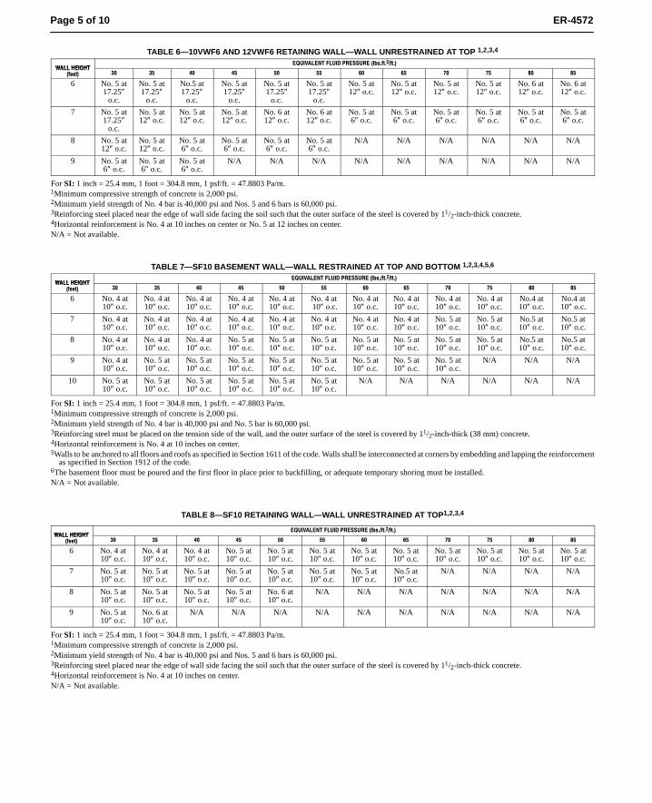
Page 5 of 10 ER-4572
TABLE 6—10VWF6 AND 12VWF6 RETAINING WALL—WALL UNRESTRAINED AT TOP 1,2,3,4
���� �������������� ���� ������� ��������������
���� ������������ �� � !� ! � "� " #� # $� $
6 No. 5 at17.25″
o.c.
No. 5 at17.25″
o.c.
No.5 at17.25″
o.c.
No. 5 at17.25″
o.c.
No. 5 at17.25″
o.c.
No. 5 at17.25″
o.c.
No. 5 at12″ o.c.
No. 5 at12″ o.c.
No. 5 at12″ o.c.
No. 5 at12″ o.c.
No. 6 at12″ o.c.
No. 6 at12″ o.c.
7 No. 5 at17.25″
o.c.
No. 5 at12″ o.c.
No. 5 at12″ o.c.
No. 5 at12″ o.c.
No. 6 at12″ o.c.
No. 6 at12″ o.c.
No. 5 at6″ o.c.
No. 5 at6″ o.c.
No. 5 at6″ o.c.
No. 5 at6″ o.c.
No. 5 at6″ o.c.
No. 5 at6″ o.c.
8 No. 5 at12″ o.c.
No. 5 at12″ o.c.
No. 5 at6″ o.c.
No. 5 at6″ o.c.
No. 5 at6″ o.c.
No. 5 at6″ o.c.
N/A N/A N/A N/A N/A N/A
9 No. 5 at6″ o.c.
No. 5 at6″ o.c.
No. 5 at6″ o.c.
N/A N/A N/A N/A N/A N/A N/A N/A N/A
For SI: 1 inch = 25.4 mm, 1 foot = 304.8 mm, 1 psf/ft. = 47.8803 Pa/m.1Minimum compressive strength of concrete is 2,000 psi.2Minimum yield strength of No. 4 bar is 40,000 psi and Nos. 5 and 6 bars is 60,000 psi.3Reinforcing steel placed near the edge of wall side facing the soil such that the outer surface of the steel is covered by 11/2-inch-thick concrete.4Horizontal reinforcement is No. 4 at 10 inches on center or No. 5 at 12 inches on center.N/A = Not available.
TABLE 7—SF10 BASEMENT WALL—WALL RESTRAINED AT TOP AND BOTTOM 1,2,3,4,5,6
���� �������������� ���� ������� ���������������
���� ������������ �� � !� ! � "� " #� # $� $
6 No. 4 at10″ o.c.
No. 4 at10″ o.c.
No. 4 at10″ o.c.
No. 4 at10″ o.c.
No. 4 at10″ o.c.
No. 4 at 10″ o.c.
No. 4 at10″ o.c.
No. 4 at10″ o.c.
No. 4 at10″ o.c.
No. 4 at10″ o.c.
No.4 at10″ o.c.
No.4 at10″ o.c.
7 No. 4 at10″ o.c.
No. 4 at10″ o.c.
No. 4 at10″ o.c.
No. 4 at10″ o.c.
No. 4 at10″ o.c.
No. 4 at10″ o.c.
No. 4 at10″ o.c.
No. 4 at10″ o.c.
No. 5 at10″ o.c.
No. 5 at10″ o.c.
No.5 at10″ o.c.
No.5 at10″ o.c.
8 No. 4 at10″ o.c.
No. 4 at10″ o.c.
No. 4 at10″ o.c.
No. 5 at10″ o.c.
No. 5 at10″ o.c.
No. 5 at10″ o.c.
No. 5 at10″ o.c.
No. 5 at10″ o.c.
No. 5 at10″ o.c.
No. 5 at10″ o.c.
No.5 at10″ o.c.
No.5 at10″ o.c.
9 No. 4 at10″ o.c.
No. 5 at10″ o.c.
No. 5 at10″ o.c.
No. 5 at10″ o.c.
No. 5 at10″ o.c.
No. 5 at10″ o.c.
No. 5 at10″ o.c.
No. 5 at10″ o.c.
No. 5 at10″ o.c.
N/A N/A N/A
10 No. 5 at10″ o.c.
No. 5 at10″ o.c.
No. 5 at10″ o.c.
No. 5 at10″ o.c.
No. 5 at10″ o.c.
No. 5 at10″ o.c.
N/A N/A N/A N/A N/A N/A
For SI: 1 inch = 25.4 mm, 1 foot = 304.8 mm, 1 psf/ft. = 47.8803 Pa/m.1Minimum compressive strength of concrete is 2,000 psi.2Minimum yield strength of No. 4 bar is 40,000 psi and No. 5 bar is 60,000 psi.3Reinforcing steel must be placed on the tension side of the wall, and the outer surface of the steel is covered by 11/2-inch-thick (38 mm) concrete.4Horizontal reinforcement is No. 4 at 10 inches on center.5Walls to be anchored to all floors and roofs as specified in Section 1611 of the code. Walls shall be interconnected at corners by embedding and lapping the reinforcement
as specified in Section 1912 of the code.6The basement floor must be poured and the first floor in place prior to backfilling, or adequate temporary shoring must be installed.N/A = Not available.
TABLE 8—SF10 RETAINING WALL—WALL UNRESTRAINED AT TOP1,2,3,4
���� �������������� ���� ������� ���������������
���� ������������ �� � !� ! � "� " #� # $� $
6 No. 4 at10″ o.c.
No. 4 at10″ o.c.
No. 4 at10″ o.c.
No. 5 at10″ o.c.
No. 5 at10″ o.c.
No. 5 at10″ o.c.
No. 5 at10″ o.c.
No. 5 at10″ o.c.
No. 5 at10″ o.c.
No. 5 at10″ o.c.
No. 5 at10″ o.c.
No. 5 at10″ o.c.
7 No. 5 at10″ o.c.
No. 5 at10″ o.c.
No. 5 at10″ o.c.
No. 5 at10″ o.c.
No. 5 at10″ o.c.
No. 5 at10″ o.c.
No. 5 at10″ o.c.
No.5 at10″ o.c.
N/A N/A N/A N/A
8 No. 5 at10″ o.c.
No. 5 at10″ o.c.
No. 5 at10″ o.c.
No. 5 at10″ o.c.
No. 6 at10″ o.c.
N/A N/A N/A N/A N/A N/A N/A
9 No. 5 at10″ o.c.
No. 6 at10″ o.c.
N/A N/A N/A N/A N/A N/A N/A N/A N/A N/A
For SI: 1 inch = 25.4 mm, 1 foot = 304.8 mm, 1 psf/ft. = 47.8803 Pa/m.1Minimum compressive strength of concrete is 2,000 psi.2Minimum yield strength of No. 4 bar is 40,000 psi and Nos. 5 and 6 bars is 60,000 psi.3Reinforcing steel placed near the edge of wall side facing the soil such that the outer surface of the steel is covered by 11/2-inch-thick concrete.4Horizontal reinforcement is No. 4 at 10 inches on center.N/A = Not available.
Page 6 of 10 ER-4572
FIGURE 1—STANDARD FORM SF SERIESFor SI: 1 inch = 25.4 mm, 1 foot = 304.8 mm.
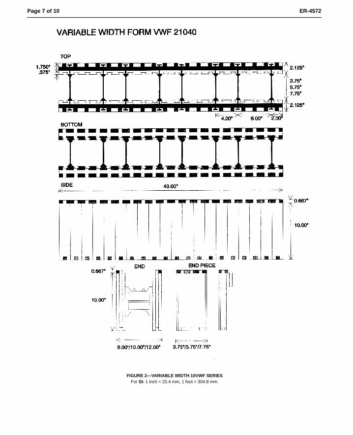
Page 7 of 10 ER-4572
FIGURE 2—VARIABLE WIDTH 10VWF SERIESFor SI: 1 inch = 25.4 mm, 1 foot = 304.8 mm.
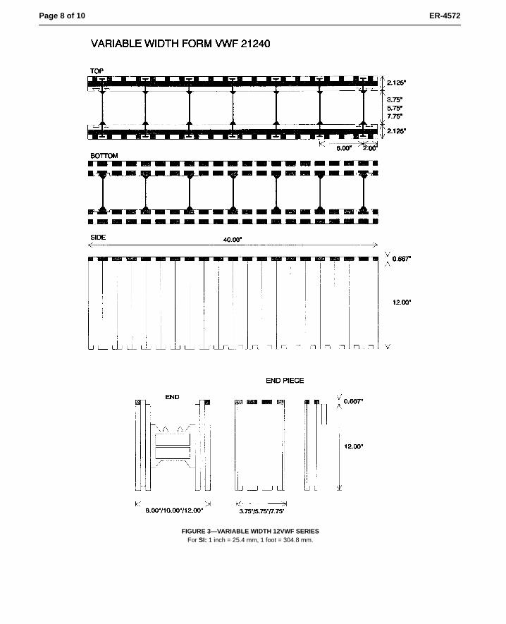
Page 8 of 10 ER-4572
FIGURE 3—VARIABLE WIDTH 12VWF SERIESFor SI: 1 inch = 25.4 mm, 1 foot = 304.8 mm.
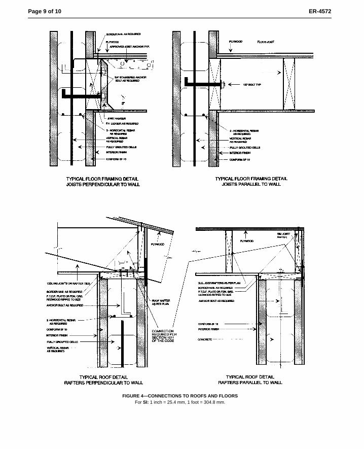
Page 9 of 10 ER-4572
FIGURE 4—CONNECTIONS TO ROOFS AND FLOORSFor SI: 1 inch = 25.4 mm, 1 foot = 304.8 mm.
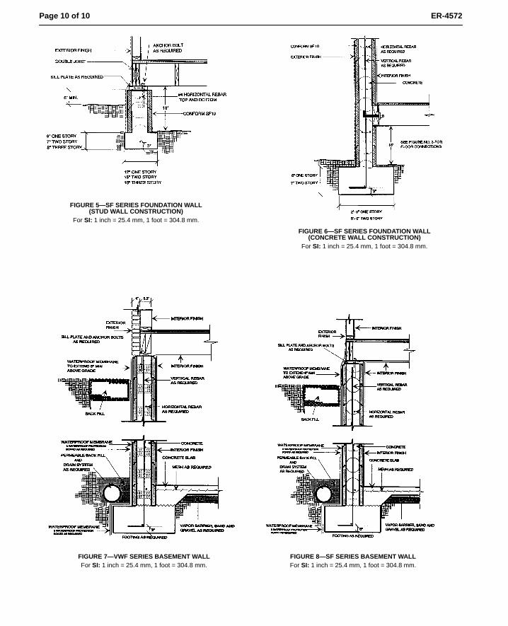
Page 10 of 10 ER-4572
FIGURE 5—SF SERIES FOUNDATION WALL(STUD WALL CONSTRUCTION)
For SI: 1 inch = 25.4 mm, 1 foot = 304.8 mm.
FIGURE 6—SF SERIES FOUNDATION WALL(CONCRETE WALL CONSTRUCTION)
For SI: 1 inch = 25.4 mm, 1 foot = 304.8 mm.
FIGURE 7—VWF SERIES BASEMENT WALLFor SI: 1 inch = 25.4 mm, 1 foot = 304.8 mm.
FIGURE 8—SF SERIES BASEMENT WALLFor SI: 1 inch = 25.4 mm, 1 foot = 304.8 mm.
BOCA International Evaluation ServicesInternational Evaluation Services
evaluation scopeCompliance with the following codes:
BOCA National Building Code/1999
# Section 106.4 Alternative materials andequipment
# Section 1214.2 Air-Borne Noise# Section1301.1 General## Section 1704.3 Labeling# Section 1909.1 Design of formwork## Section 2603.2 Labeling# Section 2603.3 Surface burning
characteristics# Section 2603.4.1.4 Attics and crawl
spaces
description
SmartBlock™ SF and VWF Forms are intendedas permanent modular formwork for use inconstruction of plain and reinforced concretewalls and components including: grade beams,piers, step foundation walls, stem walls, retain-ing walls, basement walls, loadbearing andnonloadbearing interior walls, loadbearing andnonloadbearing exterior walls, sound barrierwalls, fences, landscape walls, and exposedconditions within a crawl space.
The SF and VWF forms are modular blocks 40inches (1 m) long, and 102/3 or 123/4 inches (273to 324 mm) tall. Each block has two opposingfaces of 2 pcf expanded polystyrene (EPS), 13/4
to 21/8 inches (44 to 54 mm) thick. The voidcreated by these faces is filled with concrete andrequired reinforcing steel. The EPS is manufac-tured from beads, which are manufactured byBASF Corporation (NER-479) and HuntsmanChemical Corporation (NER-384). The resultingminimum thickness of the concrete is 61/2 inches(165 mm). See Figure 1 of this report.
The opposing faces of the VWF form units areconnected with field-installed red (12 inch), blue(10 inch), or yellow (8 inch) polypropyleneplastic ties, depending upon the nominal wallthickness being assembled. VWF form units areavailable in two models(21040 & 21240), whichare identical except for the spacing of the plasticties, as illustrated in Figures 2 and 3 of thisreport. Separate end pieces are used to closeform ends. The resulting thickness of concreteis 73/4, 53/4 and 33/4 inches (197, 146 and 95 mm)respectively.
conditions of use
This report is limited to the applications andproducts as stated. BOCA-ES intends that thereport be used by the code official to determinethat the subject of the report complies with thecode requirements specifically addressed,provided the product is installed in accordancewith the following conditions:
# American Conform Industries, Inc. shallprovide the user of this report with completeinstructions on the installation of Smart-Block™ SF and VWF. Where manufacturer'sinstallation instructions differ from this re-port, this report shall be null and void. Infor-mation within the manufacturer's installationinstructions that is not specifically evaluatedherein is beyond the scope of this report.
# SmartBlock™ SF and SmartBlock™ VWFshall be constructed to a maximum unfilledheight of 10 feet. Maximum concrete pourrates shall be as indicated in Table 1 of thisreport.
# Maximum size aggregate for the SmartBlock™SF and VWF shall be 3/8 inch.
# When the SmartBlock™ system is used toform exterior walls, the type of constructionshall be limited to Type 5.
Exception: Installations complying with Sec-tion 2603.6.8 of the BOCA NationalBuilding Code/1999.
# The SmartBlock™ SF and VWF shall beseparated from the interior of the building bya thermal barrier of 1/2-inch gypsum board orequivalent approved material, attached in anapproved manner, in accordance with Section2603.4 of the BOCA National BuildingCode/1999.Exception: On the interior side of crawl
spaces, SmartBlock™ SF and VWF mate-rial does not require an ignition barrier, asrequired by Section 2603.4.1.4 of theBOCA National Building Code/1999, toseparate it from the interior when all of thefollowing conditions exist:
! Entry is made only for service of utilities;! There are no interconnected spaces
intended for human occupancy;! The air in the crawl space or attic is not
circulated to other parts of the building;and,
(Continued on next page)
DIVISION 03CONCRETE
Section 03130Permanent Forms
MANUFACTURER:
American ConformIndustries, Inc.
1820 South Santa FeSanta Ana, CA 92705
EVALUATION SUBJECT:
SMARTBLOCK™ SF ANDVWF FORMS
Research Report
95•46PRINTED MARCH, 1999
Page 1 of 6
Copyright© 1999,BOCA Evaluation Services, Inc.
A Participating Memberof the NES, Inc.
Research Report 95-46 Page 2 of 6
BOCA International Evaluation Services
conditions of use (Continued)
! Additional thicknesses of foamed plastic are not installedover the exposed forms.
# Use of SmartBlock™ SF and VWF has not been evaluated foruse as a component of a fireresistance rated assembly.
# R-values of systems utilizing the SmartBlock™ SF and VWFshall be limited to those indicated in Table 2 of this report.
# When SmartBlock™ is utilized to provide sound transmissioncontrol between dwelling units or between dwelling units andpublic or service areas in accordance with Section 1214.2 ofthe BOCA National Building Code/1999, the following shallapply:
! The concrete formed by SmartBlock™ shall be minimum6 in. thick;
! Concrete density shall be 150 pcf, and shall fill the entirevoid within the SF unit; and
! Minimum 1/2 inch thick of gypsum wallboard conformingto ASTM C36, shall be installed on each exterior face ofthe SF unit and caulked with nonhardening sealant at itsentire perimeter.
items requiring verification
The following items are related to the use of the report subject,but are not within the scope of this evaluation. However, theseitems are related to the determination of code compliance:
UU Design calculations and details verifying the ability of thewalls, formed by SmartBlock, to carry all superimposed loadsplaced upon them as required by Chapter 16 of the BOCANational Building Code/1999. These documents shall beprepared by an individual competent and qualified in theapplication of the structural design principles involved. Theindividual shall possess the registration of license in accor-dance with the professional registration laws of the state inwhich the project is constructed.
UU Compliance with the BOCA National Building Code/1999,and the American Concrete Institute's Building CodeRequirements for Structural Concrete, 1995 (ACI 318-95), forconcrete design and construction, including but not limitedto the following:
! Concrete consolidation. Vibration shall be used forconsolidation only.
UU Special inspections in accordance with Section 1705.4 of theBOCA National Building Code/1999, to include, but not belimited to: concrete, reinforcing steel and formwork materials,installation of reinforcing steel, formwork installation andbracing, and concreting operations.
UU Weather-resistant covering, in accordance with Chapter 14 ofthe BOCA National Building Code/1999, when the Smart-Block™ SF and VWF are exposed to the exterior.
UU Waterproofing or dampproofing in accordance with Section1813.0 of the BOCA National Building Code/1999, and theapplication of materials to SmartBlock™ including, but notlimited to the following:
! Compatibility of applied materials with the EPS. The EPS
is not compatible with organic solvents such as hydrocar-bons, chlorinated hydrocarbons, ketones and esters.
! Use of coal tar pitch and emulsions is not permitted.
! Hot applications of materials shall not be in excess of 200degrees F.
UU Installation method for the attachment of interior and exteriorfinishes.
UU Installations complying with Section 2603.6.8 of the BOCANational Building Code/1999, for buildings other than Type5 construction.
UU Fireblocking in accordance with Section 721.0 of the BOCANational Building Code/1999. SmartBlock has not beenevaluated as a fireblocking. Therefore, approved fireblockingshall be installed in place of SmartBlock at locations wherefireblocking is required, such as but not limited to, ceilingand floor or roof levels in concealed wall spaces.
UU Method of rodent and insect infestation and penetrationprotection, for installations of the SmartBlock SF units thatretain earth.
information submitted
# Portland Cement Association Publication No. RD066, entitledSound Transmission Loss Through Concrete and ConcreteMasonry Walls, by Albert Litvin and Harold W. Belliston,dated 1978, containing results of testing of 6 in. and 8 in.plain concrete in accordance with ASTM E90.
# Project No. 19-020-2, dated February 19, 1992, prepared byEdward L. Pack, P.E., containing results of an engineeringanalysis regarding the sound transmission characteristics ofthe SmartBlock system.
# ITL, Inc., Report No. TR0746, dated March 24, 1992, preparedby R.A Bouvier, containing results of hydrostatic bursttesting.
# Calculations, dated December 1, 1996, signed and sealed byDouglas J. Schoonover, P.E., containing calculations todetermine allowable concrete flow rates. See Table 1 of thisreport for a summary of the results.
# Southwest Research Institute Project No. 01-7522-405, datedJune 1996, signed by Alex B. Wenzel, containing results ofcrawl space fire tests, which indicate that the contribution tofire and fire spread of the 2 pcf EPS material manufactured byHuntsman was less that of R-11 fiberglass insulation, whenapplied to the foundation wall.
# Southwest Research Institute Project No. 01-7788-205, datedFebruary 1996, signed by Alex B. Wenzel, containing resultsof crawl space fire tests, which indicate that the contributionto fire and fire spread of the 2 pcf EPS material manufacturedby BASF was less that of R-11 fiberglass insulation, whenapplied to the foundation wall.
# Report entitled, Description of the R and U Value Determina-tions for a Test Wall, 701/2O × 793/4O × 97/8O, Composed of(American) Conform's EPS Forms Filled with Concrete,prepared by H.F. Poppendiek and R.J. Whaley of GeoscienceLtd., dated March 1992, reporting the R value of the SF formunits in accordance with the procedures of ASTM C 236.
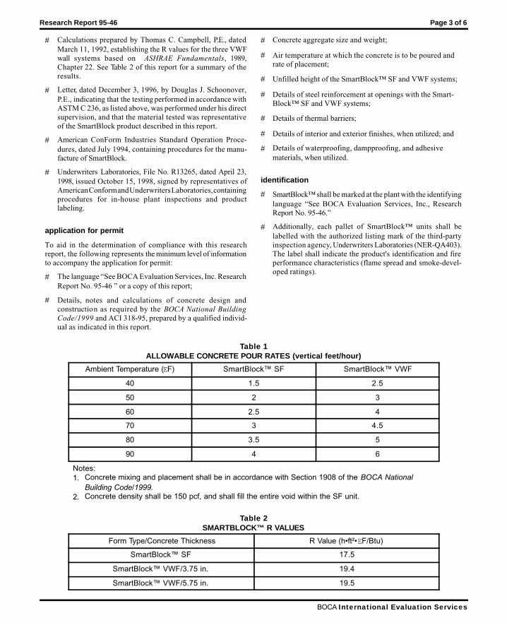
Research Report 95-46 Page 3 of 6
BOCA International Evaluation Services
# Calculations prepared by Thomas C. Campbell, P.E., datedMarch 11, 1992, establishing the R values for the three VWFwall systems based on ASHRAE Fundamentals, 1989,Chapter 22. See Table 2 of this report for a summary of theresults.
# Letter, dated December 3, 1996, by Douglas J. Schoonover,P.E., indicating that the testing performed in accordance withASTM C 236, as listed above, was performed under his directsupervision, and that the material tested was representativeof the SmartBlock product described in this report.
# American ConForm Industries Standard Operation Proce-dures, dated July 1994, containing procedures for the manu-facture of SmartBlock.
# Underwriters Laboratories, File No. R13265, dated April 23,1998, issued October 15, 1998, signed by representatives ofAmerican Conform and Underwriters Laboratories, containingprocedures for in-house plant inspections and productlabeling.
application for permit
To aid in the determination of compliance with this researchreport, the following represents the minimum level of informationto accompany the application for permit:
# The language “See BOCA Evaluation Services, Inc. ResearchReport No. 95-46 ” or a copy of this report;
# Details, notes and calculations of concrete design andconstruction as required by the BOCA National BuildingCode/1999 and ACI 318-95, prepared by a qualified individ-ual as indicated in this report.
# Concrete aggregate size and weight;
# Air temperature at which the concrete is to be poured andrate of placement;
# Unfilled height of the SmartBlock™ SF and VWF systems;
# Details of steel reinforcement at openings with the Smart-Block™ SF and VWF systems;
# Details of thermal barriers;
# Details of interior and exterior finishes, when utilized; and
# Details of waterproofing, dampproofing, and adhesivematerials, when utilized.
identification
# SmartBlock™ shall be marked at the plant with the identifyinglanguage “See BOCA Evaluation Services, Inc., ResearchReport No. 95-46.”
# Additionally, each pallet of SmartBlock™ units shall belabelled with the authorized listing mark of the third-partyinspection agency, Underwriters Laboratories (NER-QA403).The label shall indicate the product's identification and fireperformance characteristics (flame spread and smoke-devel-oped ratings).
Table 1ALLOWABLE CONCRETE POUR RATES (vertical feet/hour)
Ambient Temperature (EF) SmartBlock™ SF SmartBlock™ VWF
40 1.5 2.5
50 2 3
60 2.5 4
70 3 4.5
80 3.5 5
90 4 6
Notes:1. Concrete mixing and placement shall be in accordance with Section 1908 of the BOCA National
Building Code/1999.2. Concrete density shall be 150 pcf, and shall fill the entire void within the SF unit.
Table 2SMARTBLOCK™ R VALUES
Form Type/Concrete Thickness R Value (h•ft²•EF/Btu)
SmartBlock™ SF 17.5
SmartBlock™ VWF/3.75 in. 19.4
SmartBlock™ VWF/5.75 in. 19.5
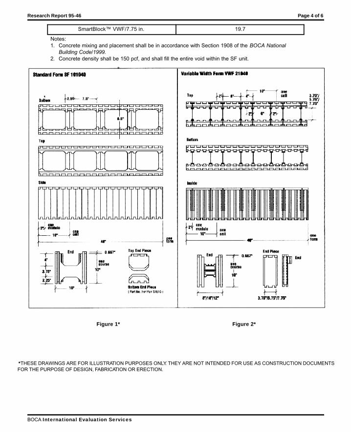
Research Report 95-46 Page 4 of 6
BOCA International Evaluation Services
SmartBlock™ VWF/7.75 in. 19.7
Notes:1. Concrete mixing and placement shall be in accordance with Section 1908 of the BOCA National
Building Code/1999.2. Concrete density shall be 150 pcf, and shall fill the entire void within the SF unit.
Figure 1* Figure 2*
*THESE DRAWINGS ARE FOR ILLUSTRATION PURPOSES ONLY. THEY ARE NOT INTENDED FOR USE AS CONSTRUCTION DOCUMENTSFOR THE PURPOSE OF DESIGN, FABRICATION OR ERECTION.
Research Report 95-46 Page 5 of 6
BOCA International Evaluation Services

#NOTICE TO REPORT USERS
This report is subject to annual certification. Reports that are not certified shall not be used or referred to. To determine the status ofcertification of this report, contact BOCA Evaluation Services, Inc., or consult the latest edition of the BOCA International ProductEvaluation Listing published periodically in the BOCA magazine.
This report is subject to the conditions listed herein and to the specific product, data and test reports submitted by the applicant requestingthis report. Independent test were not performed by BOCA Evaluation Services, Inc. and BOCA-ES specifically does not make any warranty,either expressed or implied, as to any findings or other matter in this report or as to any product covered by this report. Evaluation reportsare not to be construed as representing aesthetics or any other attributes not specifically addressed nor as an endorsement orrecommendation for the use of the report subject. This disclaimer includes, but is not limited to, merchantability.
Please contact BOCA Evaluation Services, Inc., with any questions you may have regarding this report. Additionally, please contact us
if you have any information on the performance of the product described herein which is contrary to this report.
4051 West Flossmoor Road • Country Club Hills, IL 60478-5795telephone (708) 799-2305 • fax (708) 799-0310
e-mail: [email protected] • http: //www.bocai.org

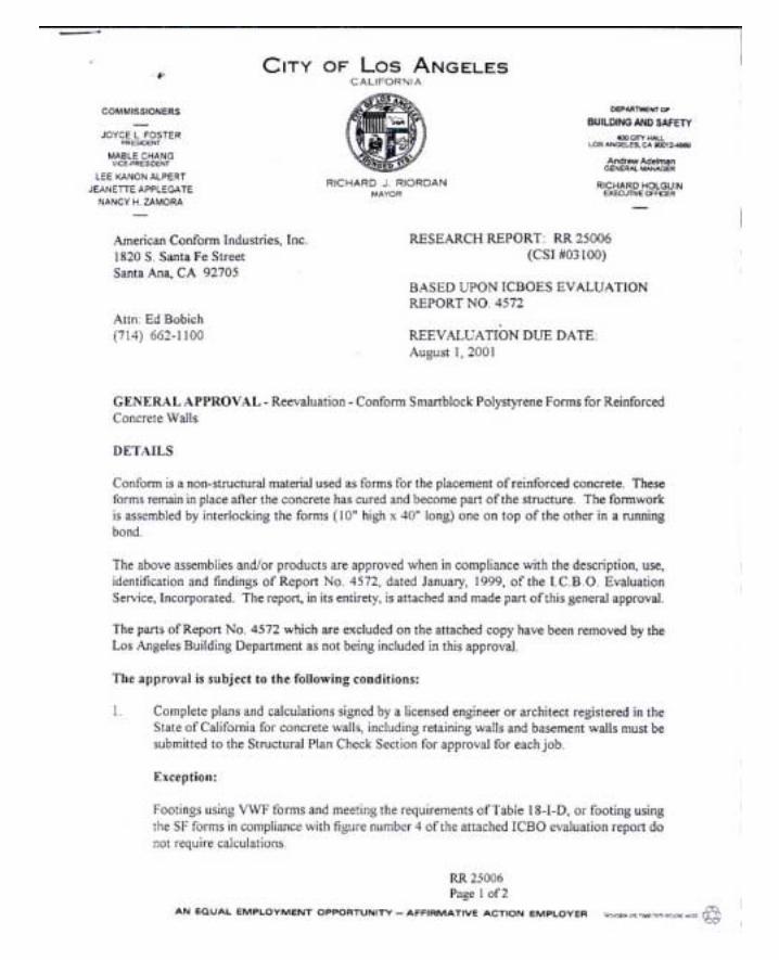
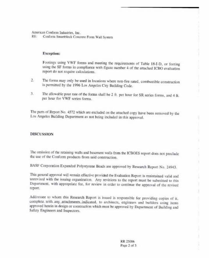
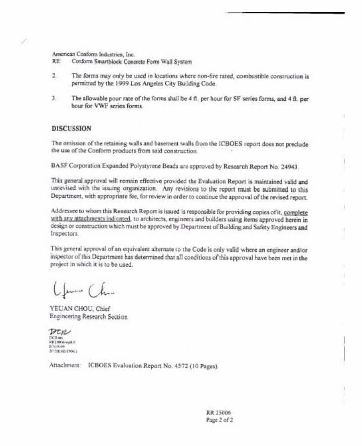

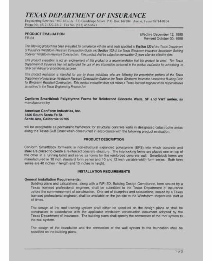
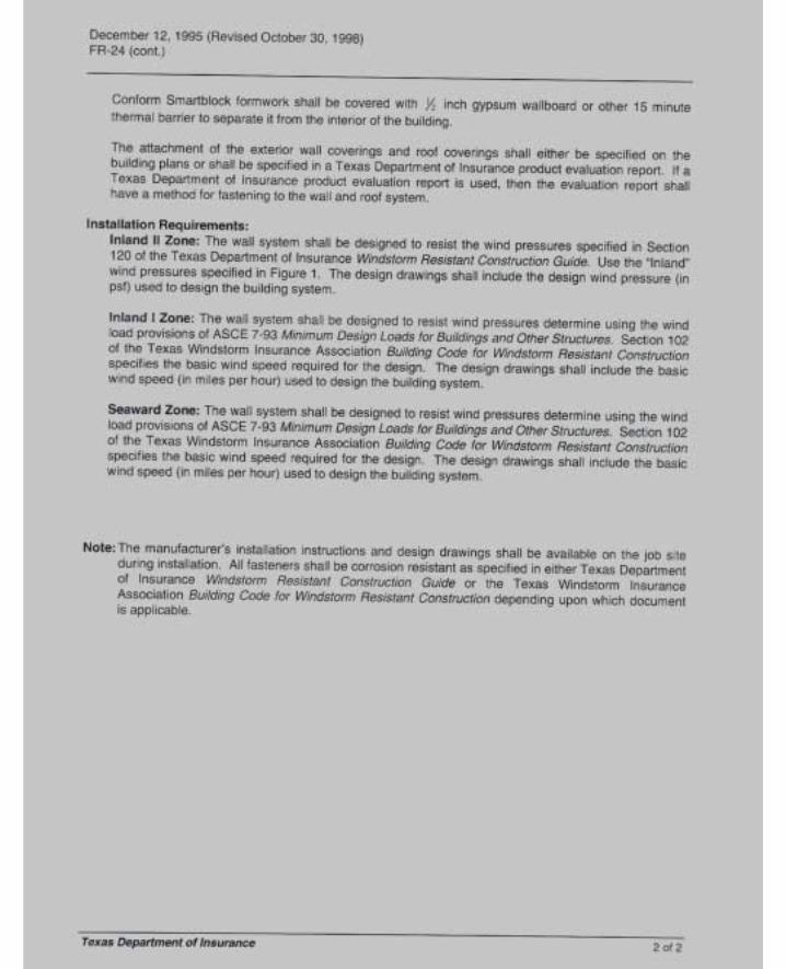

138
10.6 Structural Design Calculations for SF10 Series
ALLOWABLE AXIAL LOADS
(POUNDS PER FOOT)
WALL HEIGHT (FEET) 4’-0” 5’-0” 6’-0” 7’-0” 8’-0” 9’-0” 10’-0” 11’-0” 12’-0” 13’-0”
43,509 42,646 41,590 40,343 38,903 37,272 35,449 33,434 31,227 28,828
SF10 SERIES
REBAR @ 10” ON CENTER - VERTICAL
VERTICAL REINFORCING
STEEL
ALLOWABLE
MOMENT .9Asfy(d-a/2)
ALLOWABLE SHEAR
(. ) '85 2 f bdc
a
d
WALL
WEIGHT (PCF)
(ft - lbs. / ft) (lbs / ft) #4 CENTERED 2114 2223 .63 3.25 74.1 #4 ON EDGE 3194 3250 .63 4.75 74.1 #5 CENTERED 4219 2223 1.46 3.25 74.1 #5 ON EDGE 6625 3207 1.46 4.687
5 74.1
#6 CENTERED - - - - - #6 ON EDGE 7341 2822 2.07 4.125 74.1
f’c = 2,000 psi
Horizontal reinforcing steel = #4 @ 10” on center
fy = 40,000 psi for #3 and #4 reinforcing steel
fy = 60,000 psi for #5 and larger reinforcing steel
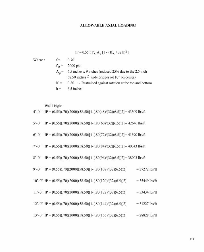
139
ALLOWABLE AXIAL LOADING
fP = 0.55 f f’c Ay [1 - (Klc / 32 h)2]
Where : f = 0.70
f’c = 2000 psi
Ag = 6.5 inches x 9 inches (reduced 25% due to the 2.5 inch
58.50 inches 2 wide bridges @ 10” on center)
K = 0.80 - Restrained against rotation at the top and bottom
h = 6.5 inches
Wall Height
4’-0” fP = (0.55)(.70)(2000)(58.50)[1-(.80(48)/(32)(6.5))2] = 43509 lbs/ft
5’-0” fP = (0.55)(.70)(2000)(58.50)[1-(.80(60)/(32)(6.5))2] = 42646 lbs/ft
6’-0” fP = (0.55)(.70)(2000)(58.50)[1-(.80(72)/(32)(6.5))2] = 41590 lbs/ft
7’-0” fP = (0.55)(.70)(2000)(58.50)[1-(.80(84)/(32)(6.5))2] = 40343 lbs/ft
8’-0” fP = (0.55)(.70)(2000)(58.50)[1-(.80(96)/(32)(6.5))2] = 38903 lbs/ft
9’-0” fP = (0.55)(.70)(2000)(58.50)[1-(.80(108)/(32)(6.5))2] = 37272 lbs/ft
10’-0” fP = (0.55)(.70)(2000)(58.50)[1-(.80(120)/(32)(6.5))2] = 35449 lbs/ft
11’-0” fP = (0.55)(.70)(2000)(58.50)[1-(.80(132)/(32)(6.5))2] = 33434 lbs/ft
12’-0” fP = (0.55)(.70)(2000)(58.50)[1-(.80(144)/(32)(6.5))2] = 31227 lbs/ft
13’-0” fP = (0.55)(.70)(2000)(58.50)[1-(.80(156)/(32)(6.5))2] = 28828 lbs/ft
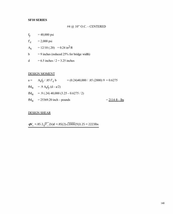
140
SF10 SERIES
#4 @ 10” O.C. - CENTERED
fy = 40,000 psi
f’c = 2,000 psi
As = 12/10 (.20) = 0.24 in2/ft
b = 9 inches (reduced 25% for bridge width)
d = 6.5 inches / 2 = 3.25 inches
DESIGN MOMENT
a = Asfy / .85 f’c b = (0.24)40,000 / .85 (2000) 9 = 0.6275
fMu = .9 Asfy (d - a/2)
fMu = .9 (.24) 40,000 (3.25 - 0.6275 / 2)
fMu = 25369.20 inch - pounds = 2114 ft - lbs
DESIGN SHEAR
φV .85 2 f' (b)d .85(2) 2000(9)3.25 2223lbsu c= = =
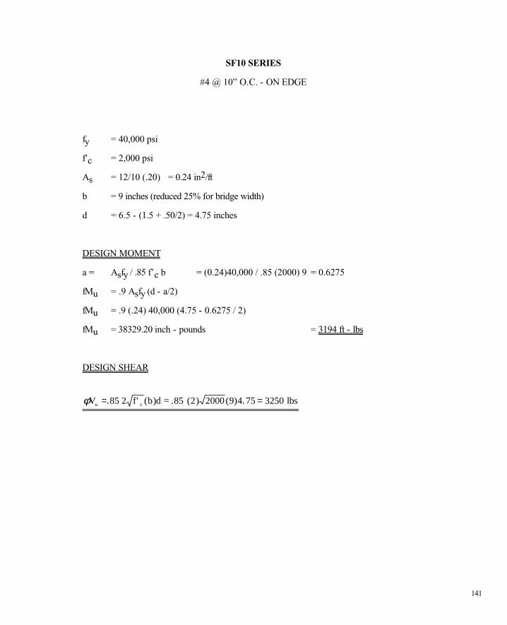
141
SF10 SERIES
#4 @ 10” O.C. - ON EDGE
fy = 40,000 psi
f’c = 2,000 psi
As = 12/10 (.20) = 0.24 in2/ft
b = 9 inches (reduced 25% for bridge width)
d = 6.5 - (1.5 + .50/2) = 4.75 inches
DESIGN MOMENT
a = Asfy / .85 f’c b = (0.24)40,000 / .85 (2000) 9 = 0.6275
fMu = .9 Asfy (d - a/2)
fMu = .9 (.24) 40,000 (4.75 - 0.6275 / 2)
fMu = 38329.20 inch - pounds = 3194 ft - lbs
DESIGN SHEAR
φV f' (b)d =.85 (2) 2000 lbsu c= =. ( ) .85 2 9 4 75 3250
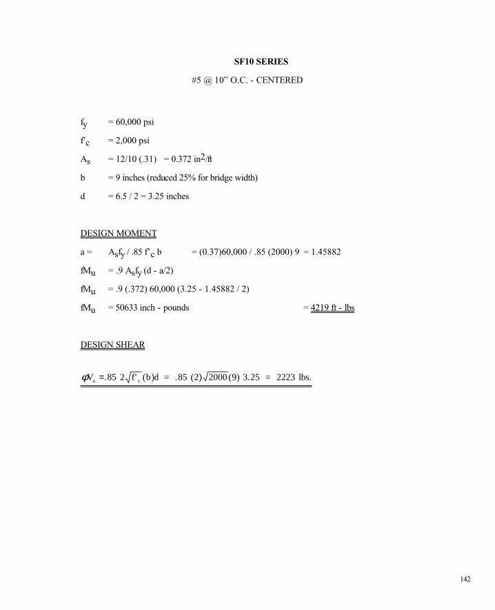
142
SF10 SERIES
#5 @ 10” O.C. - CENTERED
fy = 60,000 psi
f’c = 2,000 psi
As = 12/10 (.31) = 0.372 in2/ft
b = 9 inches (reduced 25% for bridge width)
d = 6.5 / 2 = 3.25 inches
DESIGN MOMENT
a = Asfy / .85 f’c b = (0.37)60,000 / .85 (2000) 9 = 1.45882
fMu = .9 Asfy (d - a/2)
fMu = .9 (.372) 60,000 (3.25 - 1.45882 / 2)
fMu = 50633 inch - pounds = 4219 ft - lbs
DESIGN SHEAR
φV 2 f' (b)d = .85 (2) 2000 (9) 3.25 = 2223 lbs.u c=.85
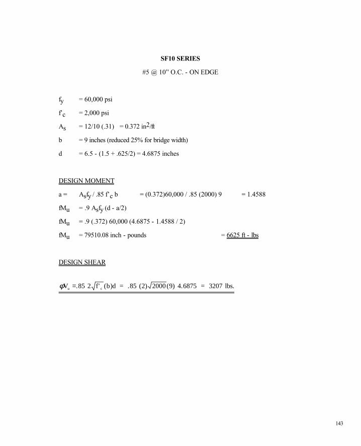
143
SF10 SERIES
#5 @ 10” O.C. - ON EDGE
fy = 60,000 psi
f’c = 2,000 psi
As = 12/10 (.31) = 0.372 in2/ft
b = 9 inches (reduced 25% for bridge width)
d = 6.5 - (1.5 + .625/2) = 4.6875 inches
DESIGN MOMENT
a = Asfy / .85 f’c b = (0.372)60,000 / .85 (2000) 9 = 1.4588
fMu = .9 Asfy (d - a/2)
fMu = .9 (.372) 60,000 (4.6875 - 1.4588 / 2)
fMu = 79510.08 inch - pounds = 6625 ft - lbs
DESIGN SHEAR
φV 2 f' (b)d = .85 (2) 2000 (9) 4.6875 = 3207 lbs.u c=.85
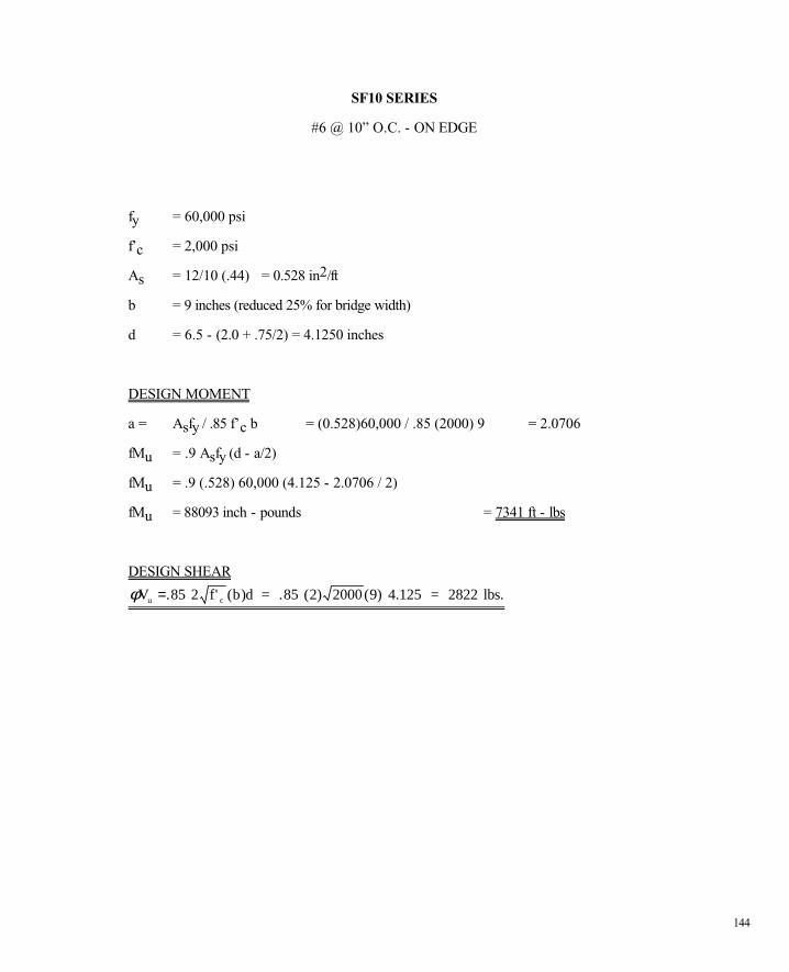
144
SF10 SERIES
#6 @ 10” O.C. - ON EDGE
fy = 60,000 psi
f’c = 2,000 psi
As = 12/10 (.44) = 0.528 in2/ft
b = 9 inches (reduced 25% for bridge width)
d = 6.5 - (2.0 + .75/2) = 4.1250 inches
DESIGN MOMENT
a = Asfy / .85 f’c b = (0.528)60,000 / .85 (2000) 9 = 2.0706
fMu = .9 Asfy (d - a/2)
fMu = .9 (.528) 60,000 (4.125 - 2.0706 / 2)
fMu = 88093 inch - pounds = 7341 ft - lbs
DESIGN SHEAR
φV 2 f' (b)d = .85 (2) 2000 (9) 4.125 = 2822 lbs.u c=.85

145
10.7 CSI TECHNICAL SPECIFICATIONS This document is arranged in agreement with the recommended section and page format
developed by CSI (Construction Specifications Institute). All versions of this document are
copyrighted by American ConForm Industries and may not be used or duplicated without
permission.
SECTION 03135
EXPANDED POLYSTYRENE CONCRETE FORMWORK
PART 1 GENERAL
1.01 SECTION INCLUDES
A. American ConForm Industries SmartBlock for cast-in-place insulated concrete, with
shoring, bracing and anchorage.
B. Required access for other work.
C. Form accessories.
1.02 INSTALLED BUT NOT FURNISHED PRODUCTS
D. Section 03300: Cast-In-Place Concrete: Supply of concrete accessories for placement
by this section.
E. Section 04300: Supply of masonry accessories for placement by this section.
F. Section 05500: Metal Fabrications: Supply of metal fabrications for placement by this
section.
1.03 RELATED SECTIONS
A. Section 03200: Concrete Reinforcement.
B. Section 03300: Cast-In-Place Concrete.
146
1.04 REFERENCES
C. ACI 301: Structural Concrete for Buildings.
D. ACI 318: Building Code Requirements for Reinforced Concrete.
E. ASTM C 578: Standard Specification for Preformed, Cellular Polystyrene Thermal
Insulation.
F. American ConForm Industries User's Manual for SmartBlock Forms.
G. Structural Calculations for SmartBlock Forms.
1.05 DESIGN REQUIREMENTS
A. A. All designing, engineering and construction of formwork, shoring and bracing must
conform to design and applicable code requirements. Concrete must conform to
required shape, lines and dimensions.
1.06 SUBMITTALS
A. Shop Drawings; identify required dimensions, materials, and arrangement.
B. Product Data; denotes form materials and installation requirements.
1.07 QUALITY ASSURANCE
A. Work is to conform to ACI 347.
B. Erection of formwork is the contractor's responsibility. Approval of the shop drawings,
by the architect of record, as submitted or as corrected does not relieve the contractor
of their responsibility to appropriately construct and maintain the forms so that they will
function properly.
1.08 REGULATORY REQUIREMENTS
A. Conform to applicable codes for designing, fabricating and erecting of formwork.

147
B. ICBO Evaluation Service, Inc. Report 4572; ConForm SmartBlock Polystyrene forms
for reinforced concrete walls.
C. BOCA International Evaluation Services, Inc. Report 95· 46: DIVISION 03,
CONCRETE; Section 03130 Permanent Forms.
1.09 DELIVERY, STORAGE, AND HANDLING
A. Deliver American ConForm Industries SmartBlock Forms, installation instructions and
user reference manual as provided by manufacturer.
B. Store as strapped, banded or other prepackaged bundles and boxes provided by the
manufacturer to prevent damage. Protect from UV deterioration due to prolonged
exposure to direct sunlight.
1.10 COORDINATION
A. Coordination of this section, with other sections requiring attachment or embedment of
components or modification of formwork, must be prearranged.
B. If erection of the formwork results in insufficient concrete cover over reinforcement,
stop construction and request instructions from the Architect/Engineer of record.
PART 2 PRODUCTS
2.01 MANUFACTURERS: PREFABRICATED FORMS
A. American ConForm Industries; Product: SmartBlock SF10 Standard Form.
B. Two opposing faces of EPS foam connected with an EPS foam bridge. An interlocking
tongue-and-groove is along top and bottom horizontal surfaces. Surface of exterior is
scored 1/16” deep on 2” increments to facilitate measuring and cutting.
C. Expanded Polystyrene Foam:
148
1. Density: 1.5 – 2.0 pcf.
2. Flame spread: ASTM E 84, 25 or less.
3. Smoke Developed: ASTM E 84, 450 or less.
D. Substitutions: Under provisions of Section 01600.
2.02 MANUFACTURERS: UNASSEMBLED FORMS
A. American ConForm Industries; Product: SmartBlock 12VWF Variable Width Form.
B. Two opposing faces of EPS foam connected with polypropylene connectors manually
inserted into preformed “T” slots in the foam. Connector flange is 1 ¼” wide by 6” long
and after proper positioning, is ¼” below the surface of the foam panel. An interlocking
tongue-and-groove is along top and bottom horizontal surfaces. Surface of exterior is
scored 1/16” deep on 2” increments to facilitate measuring and cutting.
C. Expanded Polystyrene Foam:
1. Density: 1.5 – 2.0 pcf.
2. Flame spread: ASTM E 84, 25 or less.
3. Smoke Developed: ASTM E 84, 450 or less.
D. Substitutions: Under provisions of Section 01600.
2.03 ACCESSORIES
A. Bracing: Commercially available systems or nominal lumber or steel framing members.
B. Cleat or Sleepers: Nominal lumber or steel framing members.
C. Tape: Release tape for securing, protecting and sealing slots, corners, adjustment cuts,
interlocking tongue and groove.
D. Nails, Tie Wire, Lag Bolts, Through Bolts, Anchorages: Sized as required, of sufficient
strength and composition to maintain formwork positioning while placing concrete.
149
PART 3 EXECUTION
3.01 EXAMINATION
A. Dimensional lines, levels and centers of foundation must be verified before erecting
formwork. Dimensions must agree with drawings.
B. Strength of foundation concrete to be verified before proceeding with erecting
formwork.
3.02 ERECTION: FORMWORK
A. American ConForm Industries SmartBlock Forms must be installed in accordance with
manufacturer's recommendations. Erect SmartBlock forms in a running bond. Corners
are overlapped “log cabin” style. Protect forms and connectors from damage.
B. Erect formwork, shoring and bracing to achieve design requirements. All work must
conform to ACI 301 requirements.
C. Bracing and shoring must ensure stability of formwork and support construction loads.
D. Design, erect, support, brace, and maintain formwork to support axial, lateral, dynamic
and static loads and moments that may occur until such forces can be resisted by the
concrete structure. Resultant concrete, members and structures must be of correct
shape, size, position, elevation and alignment.
E. Plumb and align all joints.
F. Approval of the Architect/Engineer of record must be obtained before framing openings
not indicated on drawings.
3.03 EMBEDDED PARTS, OPENINGS AND INSERTS.
A. Locate, set in place and stabilize items to be cast directly into concrete.
B. Openings, where required, must be formed and stabilized.
150
C. Work with other sections must be coordinated before locating, forming, placing and
stabilizing openings, sleeves, slots, pockets, recesses, bolts, anchors, other inserts and
components.
D. Positioning of items must conform to the appropriate section. Masonry anchors must
conform to spacing and intervals specified in Section 04300.
E. Manufactures instructions for installation of accessories must be followed. Positioning
must not be compromised during placement of the concrete.
3.04 FORM MAINTENANCE
A. Remove foreign matter on exterior and interior of forms before placing into position.
B. Cavities must be clear of debris prior to concrete placement.
C. Compressed air or water can be used to remove remaining foreign matter. Ensure
clean-outs allow water and debris can drain to exterior.
D. In cold weather, remove ice and snow from interior cavity of forms. Do not use de-icing
salts or other chemicals. Unless formwork is within heated space, do not use water to
clean out forms. Use compressed air or other method approved by the
Architect/Engineer of record to remove foreign matter.
E. Wall finishes requiring bonding to the EPS foam can only be applied to a clean surface.
Oxidation, from UV exposure, in the form of yellow dust must be removed from the
exterior surfaces. Mild detergent and a stiff brush or pressure washers may be used.
Rinse thoroughly with water.
3.05 TOLERANCES OF FORMWORK
A. Tolerances of formwork must be maintained in accordance with ACI 301.
3.06 FIELD QUALITY ASSURANCE
151
A. Before placement of concrete, inspect erected formwork, shoring, and bracing. Ensure
formwork conforms to design, stability and cleanliness and that shoring, bracing,
supports, fastenings, ties, accessories and other items are secure and maintain their
positions.
END OF SECTION
