design • manufacture • construct - sisau · 4 sis is a unique organisation focused on...
TRANSCRIPT

V3.3
• Design• Manufacture
• Construct
2
TIMBER STEEL CONCRETE
StructuralComp™FIBRE REINFORCED PLASTIC COMPOSITERECYCLED WOOD PLASTIC COMPOSITECoreSpan™FIBRE REINFORCED/WOOD PLASTIC MULTI COMPOSITE

3
Introduction . . . . . . . . . . . . . . . . . . . . . . . . . . . . . . . . . . . . . . . . . . . . . . . . . . . . . . . . . . . . . . . . . . . . . . .4Contact Us . . . . . . . . . . . . . . . . . . . . . . . . . . . . . . . . . . . . . . . . . . . . . . . . . . . . . . . . . . . . . . . . . . . . . . . .5Manufacturing . . . . . . . . . . . . . . . . . . . . . . . . . . . . . . . . . . . . . . . . . . . . . . . . . . . . . . . . . . . . . . . . . . . . .6Pedestrian Structures – General . . . . . . . . . . . . . . . . . . . . . . . . . . . . . . . . . . . . . . . . . . . . . . . . . . . . . .7 SISCo-FC™ Systems Structure Design . . . . . . . . . . . . . . . . . . . . . . . . . . . . . . . . . . . . . . . . . . . . . . . . .10Installation Tolerances . . . . . . . . . . . . . . . . . . . . . . . . . . . . . . . . . . . . . . . . . . . . . . . . . . . . . . . . . . . . .13Engineering / Spans - StructuralComp™ FRP / WPC . . . . . . . . . . . . . . . . . . . . . . . . . . . . . . . . . . . . 14Plastics Engineered for Strength . . . . . . . . . . . . . . . . . . . . . . . . . . . . . . . . . . . . . . . . . . . . . . . . . . . . .18SISCo-FC™ Materials . . . . . . . . . . . . . . . . . . . . . . . . . . . . . . . . . . . . . . . . . . . . . . . . . . . . . . . . . . . . . . .19Material Description . . . . . . . . . . . . . . . . . . . . . . . . . . . . . . . . . . . . . . . . . . . . . . . . . . . . . . . . . . . . . . .20History of FRP in Construction . . . . . . . . . . . . . . . . . . . . . . . . . . . . . . . . . . . . . . . . . . . . . . . . . . . . . . . .25Fixing Methodology . . . . . . . . . . . . . . . . . . . . . . . . . . . . . . . . . . . . . . . . . . . . . . . . . . . . . . . . . . . . . . .28StructuralComp™ Super Structure Brackets . . . . . . . . . . . . . . . . . . . . . . . . . . . . . . . . . . . . . . . . . . .29Superstructure Connection Detail . . . . . . . . . . . . . . . . . . . . . . . . . . . . . . . . . . . . . . . . . . . . . . . . . . .30Typical Detail . . . . . . . . . . . . . . . . . . . . . . . . . . . . . . . . . . . . . . . . . . . . . . . . . . . . . . . . . . . . . . . . . . . . .51SISCo-FC™ WPC Decking / FRP Decking & Grating Options . . . . . . . . . . . . . . . . . . . . . . . . . . . . . 63StructuralComp™ FRP Grating - Profile Options . . . . . . . . . . . . . . . . . . . . . . . . . . . . . . . . . . . . . . . .64CoreSpan™ WPC / FRP Decking & WPC Decking . . . . . . . . . . . . . . . . . . . . . . . . . . . . . . . . . . . . . . 67Project Management & Installation . . . . . . . . . . . . . . . . . . . . . . . . . . . . . . . . . . . . . . . . . . . . . . . . . .69Typical Project Timelines . . . . . . . . . . . . . . . . . . . . . . . . . . . . . . . . . . . . . . . . . . . . . . . . . . . . . . . . . . . .72Pricing . . . . . . . . . . . . . . . . . . . . . . . . . . . . . . . . . . . . . . . . . . . . . . . . . . . . . . . . . . . . . . . . . . . . . . . . . . .74Component Lead Times . . . . . . . . . . . . . . . . . . . . . . . . . . . . . . . . . . . . . . . . . . . . . . . . . . . . . . . . . . . .76How to Specify . . . . . . . . . . . . . . . . . . . . . . . . . . . . . . . . . . . . . . . . . . . . . . . . . . . . . . . . . . . . . . . . . . .77Component Example Specification Code . . . . . . . . . . . . . . . . . . . . . . . . . . . . . . . . . . . . . . . . . . . .80Transport & Logistics . . . . . . . . . . . . . . . . . . . . . . . . . . . . . . . . . . . . . . . . . . . . . . . . . . . . . . . . . . . . . . .81Other Products From Sustainable Infrastructure Systems . . . . . . . . . . . . . . . . . . . . . . . . . . . . . . . . . 82SIS Product FAQs . . . . . . . . . . . . . . . . . . . . . . . . . . . . . . . . . . . . . . . . . . . . . . . . . . . . . . . . . . . . . . . . . .97Annexure 1 - SISCo-FCTM Composite Threaded Rod & Flanged Hex Nuts . . . . . . . . . . . . . . . . . 103Annexure 2 - Testing of SISCo-FC™ FRP Members . . . . . . . . . . . . . . . . . . . . . . . . . . . . . . . . . . . . . . 121Annexure 3 - Terms & Conditions of Trade . . . . . . . . . . . . . . . . . . . . . . . . . . . . . . . . . . . . . . . . . . . .147
copyright 2014 – Sustainable Infrastructure Systems (Aust) Pty Ltd
trADE MArKSSISCo-FC™, CoreSpan™ and StructuralComp™ are registered trademarks used under license by Sustainable Infrastructure Systems (Aust) Pty Ltd . License permission granted by Sustainable Infrastructure Systems (Aust) IP Pty Ltd
pAtENtS / pAtENtS pENDiNgParts of the SISCo-FC™ System are protected by either patents, or patents pending . Individual components are protected by either patents, or patents pending . Fixing methodology is protected by patents, or patents pending .
Contents

4
SIS is a unique organisation focused on manufacturing
and distributing sustainable and recycled products for
diversified clients around the world. From recycled
plastic, recycled wood plastic composites (WPC),
fibreglass reinforced plastic composites (FRP)
and recycled rubber through to co-extruded multi-
composites and OEM manufacturing, SIS are market
leaders in delivering sustainable products to customers
in Civil Infrastructure, Building & Construction, Oil &
Gas, Mining, Aviation, Aquaculture, Marine & Ports,
Transport & Logistics and Agriculture.
Drawing on a strategic distribution capability with
offices in Adelaide, Melbourne, Sydney, Brisbane,
Shanghai, Shenzhen, Hong Kong and Los Angeles, SIS
has manufacturing facilities in Australia, the People’s
Republic of China and North America. Our company
is financially strong, total quality oriented, technically
advanced, and customer focused. We specialise in the
development and manufacture of high quality sustainable
products. We utilise a holistic project management
approach to ensure the best results and measured
success of each project. We understand the importance
of product and project planning, consultation, analysis,
management, communication and support.
We have an agile business environment and utilise
a global team of highly experienced developers,
manufacturing facilities, builders and support crew
who can best meet our client’s requirements under
any given circumstances. Our strategy is founded on
diversification – by product, geography and market.
To succeed, we have in place a workforce that reflects
our values and the communities in which we operate.
We recruit from our host communities, to attract high
calibre people who are committed to the success of our
organisation and thrive on working in high performing
teams. We are committed to developing the skills and
capability of our people and believe this, underpinned
by our tier one resource base, is what differentiates us
from our competitors.
Sustainable infrastructure is not just about new
infrastructure; it is about rehabilitation, reuse or
the optimisation of existing infrastructure, which is
consistent with the principles of sustainability and
sustainable product development, whether it be from
civil infrastructure to mining sectors. This encompasses
infrastructure renewal, long-term economic analysis of
infrastructure, energy use and reduced infrastructure
costs, the protection of existing infrastructure from
environmental degradation, material selection
for sustainability, quality, durability and energy
conservation, minimising waste and materials, the
redesign of infrastructure in light of climate change
and the remediation of environmentally damaged
areas of our world. Clearly, sustainable infrastructure
will lead to improvements to mankind through better
socio-economics. Responsible design needs to balance
social, economic and environmental issues.
SIS aims to set a responsible standard of sustainable
product design and manufacture for our diverse
client base in both the short and the long term. We
all have a significant impact on the world around us
and each of us should play a part in protecting future
generations. Designers, engineers and planners have
a big responsibility to set standards of product design
that benefit the environment and the people who live
in it. SIS’s aspiration is that ultimately, talking about
sustainability will become superfluous, because it will
be the expected.
Introduction

5
Los Angeles
AdelaideMelbourne
Sydney
Brisbane
Hong Kong
ShanghaiShenzhen
hEAD oFFicEADELAIDE: 7-9 Streiff Road Wingfield, SA 5013 AUSTRALIAPH: 1300 261 074FAX: 1300 081 075EMAIL: [email protected]: www.sisau.com.au
AUStrALiAN NAtioNAL DiStriBUtioN cENtrES No Public Access Unless by Prior Appointment
SyDNEy17 Jumal Place SmithfieldNSW 2164AUSTRALIA
MELBoUrNE135 Boundary Road Laverton NorthVIC 3026AUSTRALIA
BriSBANE1094 Lytton Road MurarrieQLD 4172AUSTRALIA
iNtErNAtioNAL oFFicES
hoNg KoNgRoom 102, 1st Floor The Centre Mark 287 – 299 Queen’s Rd Central Hong Kong
ShANghAiRM 1001 Hua Sheng Building No. 398 Han Kou Rd 200001Shanghai People’s Republic of [email protected]
ShENZhEN27-3, 27th FloorShun Hing Square Di Wang Commercial Centre Lu Wu DistrictShenzhen People’s Republic of [email protected]
LoS ANgELESSuite 1355230 Pacific Concourse Dr. Los AngelesCA 90045United States of [email protected]
Contact Us

6
Products designed, manufactured and supplied by SIS embody state of the art technology and are engineered by our teams to deliver enhanced performance and sustainably effective operation for customers worldwide. All our products are manufactured to the highest industry standards, following strict quality assurance guidelines. With many employees dedicated to production, quality product and technical expertise is ensured at all times. Excellent long term relationships with our key suppliers of raw materials and components provide confidence in material quality as well as sustainable and efficient manufacturing and supply chain processes.
The close relationship with our research and development division ensures that SIS manufacturing teams can react quickly and professionally to customer needs. SIS has built a reputation based on excellent customer service, high quality manufacturing and on providing the right solution in sustainable product design and manufacturing. Continuous improvement of equipment design, materials and manufacturing technology ensures SIS maintains its capability of offering clients the latest and most commercially
viable sustainable products available. SIS also works with clients to develop specific solutions to meet their unique needs through the application of research and development efforts in a partnering relationship.
We manufacture and supply products from materials that include:
• Recycled Plastic• Recycled Plastic Panel• Fibreglass Reinforced Plastic• Recycled Wood Plastic Composite• Recycled Rubber• Aluminium / Recycled Plastic Composite
With a global network of offices and manufacturing facilities, along with projects in Africa, the Middle East, Asia, Australia and the Pacific Rim, SIS can be trusted to provide easy, efficient and seamless supply to almost all places on earth.
Manufacturing
7
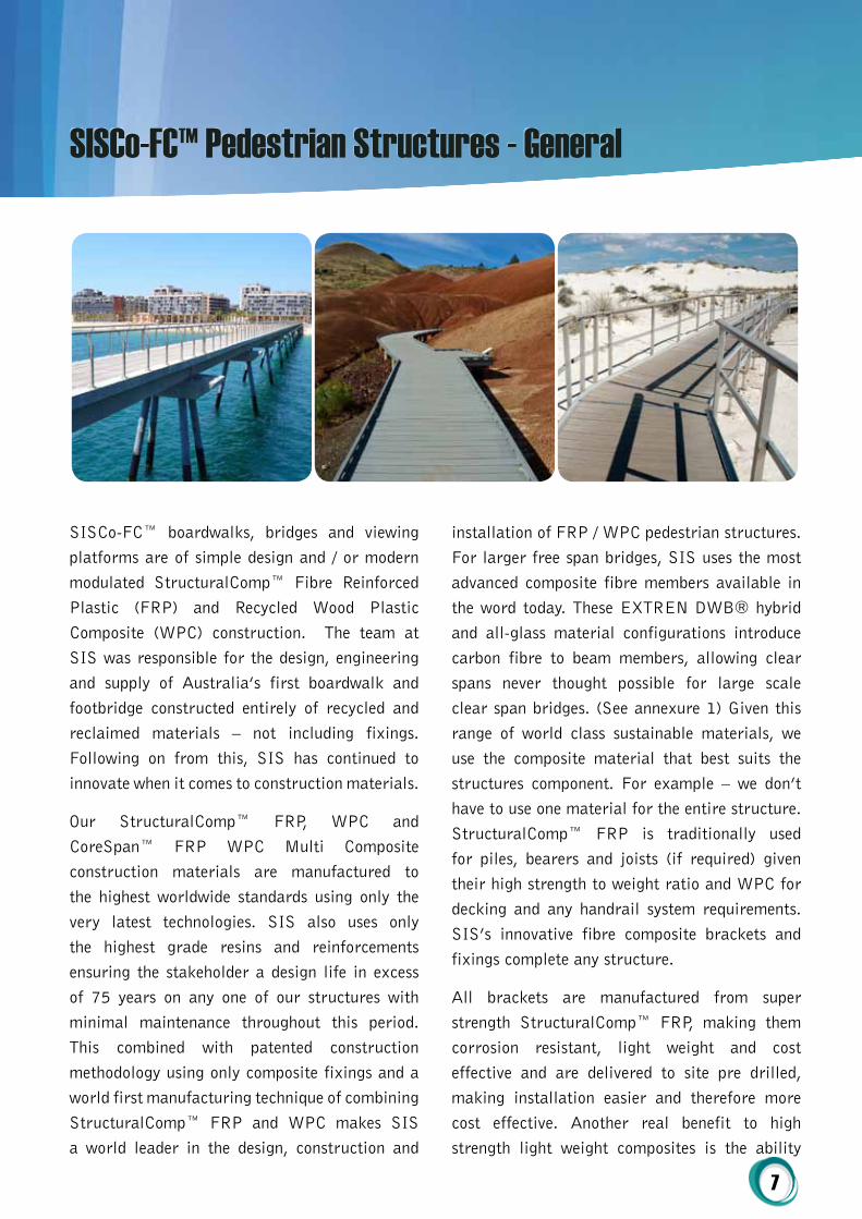
SISCo-FC™ boardwalks, bridges and viewing platforms are of simple design and / or modern modulated StructuralComp™ Fibre Reinforced Plastic (FRP) and Recycled Wood Plastic Composite (WPC) construction. The team at SIS was responsible for the design, engineering and supply of Australia’s first boardwalk and footbridge constructed entirely of recycled and reclaimed materials – not including fixings. Following on from this, SIS has continued to innovate when it comes to construction materials.
Our StructuralComp™ FRP, WPC and CoreSpan™ FRP WPC Multi Composite construction materials are manufactured to the highest worldwide standards using only the very latest technologies. SIS also uses only the highest grade resins and reinforcements ensuring the stakeholder a design life in excess of 75 years on any one of our structures with minimal maintenance throughout this period. This combined with patented construction methodology using only composite fixings and a world first manufacturing technique of combining StructuralComp™ FRP and WPC makes SIS a world leader in the design, construction and
installation of FRP / WPC pedestrian structures. For larger free span bridges, SIS uses the most advanced composite fibre members available in the word today. These EXTREN DWB® hybrid and all-glass material configurations introduce carbon fibre to beam members, allowing clear spans never thought possible for large scale clear span bridges. (See annexure 1) Given this range of world class sustainable materials, we use the composite material that best suits the structures component. For example – we don’t have to use one material for the entire structure. StructuralComp™ FRP is traditionally used for piles, bearers and joists (if required) given their high strength to weight ratio and WPC for decking and any handrail system requirements. SIS’s innovative fibre composite brackets and fixings complete any structure.
All brackets are manufactured from super strength StructuralComp™ FRP, making them corrosion resistant, light weight and cost effective and are delivered to site pre drilled, making installation easier and therefore more cost effective. Another real benefit to high strength light weight composites is the ability
SISCo-FC™ Pedestrian Structures - General
8
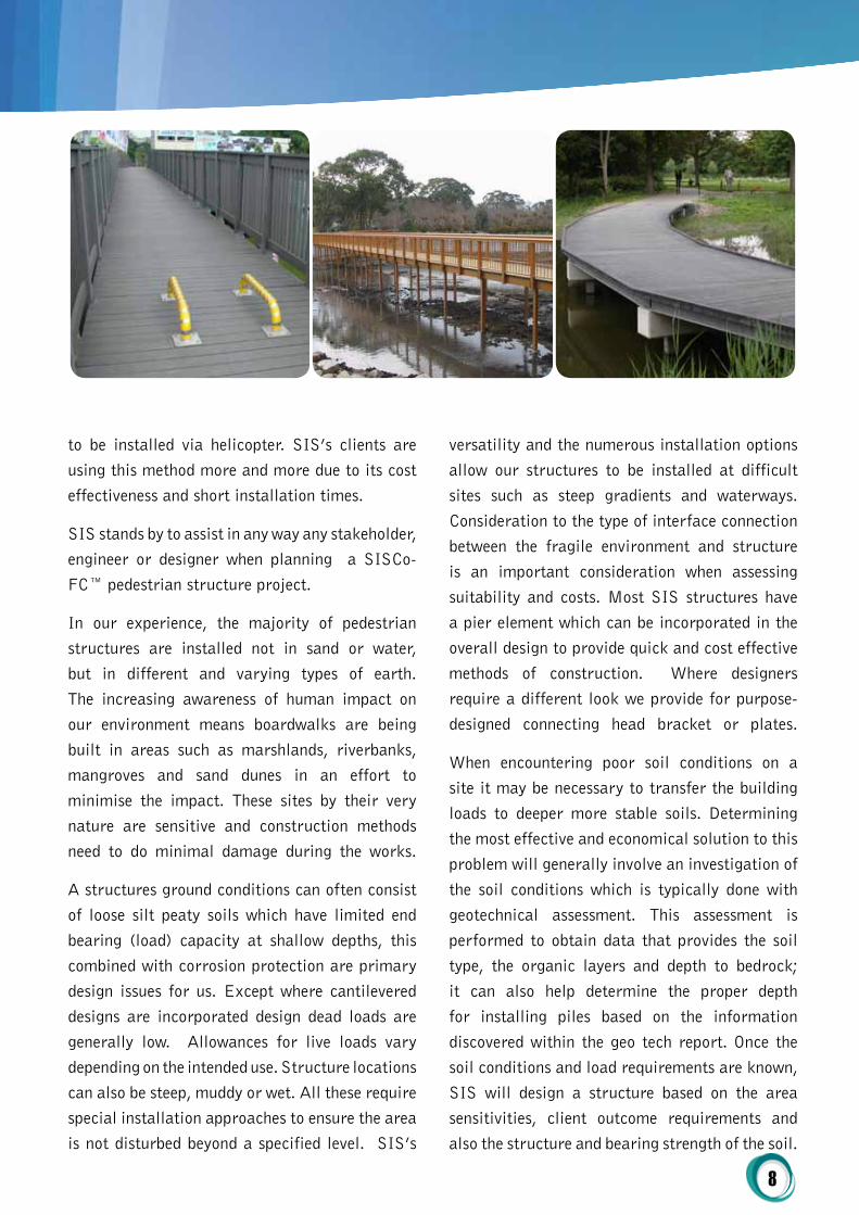
to be installed via helicopter. SIS’s clients are using this method more and more due to its cost effectiveness and short installation times.
SIS stands by to assist in any way any stakeholder, engineer or designer when planning a SISCo-FC™ pedestrian structure project.
In our experience, the majority of pedestrian structures are installed not in sand or water, but in different and varying types of earth. The increasing awareness of human impact on our environment means boardwalks are being built in areas such as marshlands, riverbanks, mangroves and sand dunes in an effort to minimise the impact. These sites by their very nature are sensitive and construction methods need to do minimal damage during the works.
A structures ground conditions can often consist of loose silt peaty soils which have limited end bearing (load) capacity at shallow depths, this combined with corrosion protection are primary design issues for us. Except where cantilevered designs are incorporated design dead loads are generally low. Allowances for live loads vary depending on the intended use. Structure locations can also be steep, muddy or wet. All these require special installation approaches to ensure the area is not disturbed beyond a specified level. SIS’s
versatility and the numerous installation options allow our structures to be installed at difficult sites such as steep gradients and waterways. Consideration to the type of interface connection between the fragile environment and structure is an important consideration when assessing suitability and costs. Most SIS structures have a pier element which can be incorporated in the overall design to provide quick and cost effective methods of construction. Where designers require a different look we provide for purpose-designed connecting head bracket or plates.
When encountering poor soil conditions on a site it may be necessary to transfer the building loads to deeper more stable soils. Determining the most effective and economical solution to this problem will generally involve an investigation of the soil conditions which is typically done with geotechnical assessment. This assessment is performed to obtain data that provides the soil type, the organic layers and depth to bedrock; it can also help determine the proper depth for installing piles based on the information discovered within the geo tech report. Once the soil conditions and load requirements are known, SIS will design a structure based on the area sensitivities, client outcome requirements and also the structure and bearing strength of the soil.
9
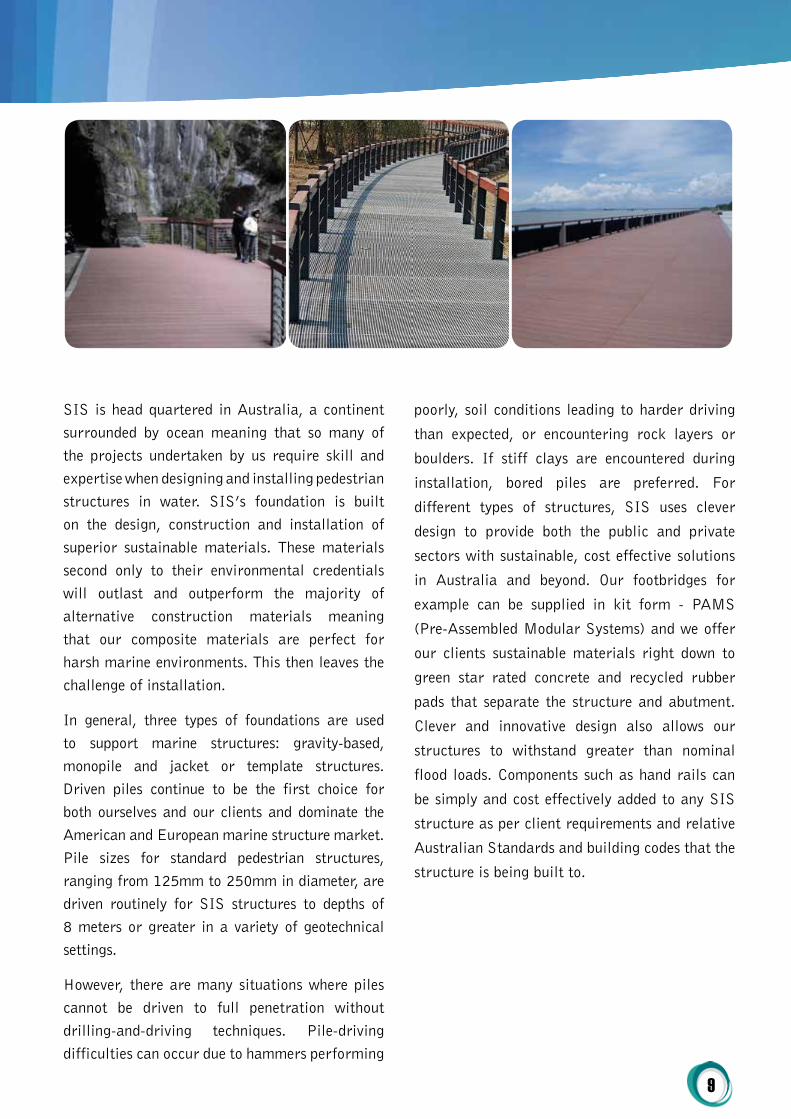
SIS is head quartered in Australia, a continent surrounded by ocean meaning that so many of the projects undertaken by us require skill and expertise when designing and installing pedestrian structures in water. SIS’s foundation is built on the design, construction and installation of superior sustainable materials. These materials second only to their environmental credentials will outlast and outperform the majority of alternative construction materials meaning that our composite materials are perfect for harsh marine environments. This then leaves the challenge of installation.
In general, three types of foundations are used to support marine structures: gravity-based, monopile and jacket or template structures. Driven piles continue to be the first choice for both ourselves and our clients and dominate the American and European marine structure market. Pile sizes for standard pedestrian structures, ranging from 125mm to 250mm in diameter, are driven routinely for SIS structures to depths of 8 meters or greater in a variety of geotechnical settings.
However, there are many situations where piles cannot be driven to full penetration without drilling-and-driving techniques. Pile-driving difficulties can occur due to hammers performing
poorly, soil conditions leading to harder driving
than expected, or encountering rock layers or
boulders. If stiff clays are encountered during
installation, bored piles are preferred. For
different types of structures, SIS uses clever
design to provide both the public and private
sectors with sustainable, cost effective solutions
in Australia and beyond. Our footbridges for
example can be supplied in kit form - PAMS
(Pre-Assembled Modular Systems) and we offer
our clients sustainable materials right down to
green star rated concrete and recycled rubber
pads that separate the structure and abutment.
Clever and innovative design also allows our
structures to withstand greater than nominal
flood loads. Components such as hand rails can
be simply and cost effectively added to any SIS
structure as per client requirements and relative
Australian Standards and building codes that the
structure is being built to.

10
Design Standard
All bridges and culverts are designed in accordance with the current edition of the Australian Bridge Design Code (SAAHB77). All bridges are designed for loading in accordance with the appropriate part(s) of the relevant Australian Standard. The client shall determine serviceability criteria that are not specifically listed in the mandatory performance criteria that form part of the SIS quoting documents. All structures shall be designed and constructed in accordance with relevant sections of the current edition of the codes and standards as published by Standards Australia and the Building Code of Australia. SIS designers shall maintain knowledge of all amendments and upgrades to standards and work shall conform to the standard current at the time of commission.
Design responsibility
The SIS designer will check all stages of design for accuracy, completeness and compliance with the Brief and relevant standards. A Design Summary Sheet shall be prepared for all structures on completion of the design, and shall be included in the set of design drawings. The Design Summary Sheet is an important feature of the design as it contains a summary of all major features of the design. It is used for future checking of the structure for heavy load movements, structural alterations or if there are any major maintenance problems. The actual contents will vary depending on the size and complexity of the structure.
The main items to include on the Design Summary Sheet are:
• Details of the span configuration;• The design cross sections used in the
analysis at critical positions – e.g. support and mid-span;
• Details of the reinforcement and / or pre-stress and the section capacities at the critical sections;
• The serviceability design moments and resulting stresses at the critical sections;
• Live Load Distribution Factors for different loadings;
• Design Live Load;• The available live load capacity at the
critical sections, for use in checking heavy load movements;
• Foundation information, i.e. design bearing pressures for spread footings and design pile loads for piled foundations;
Sustainable Design principles
SIS is committed to sustainable development and continuous improvement in environmental protection. We aim to conserve and reduce resources where possible and ensure we comply with all relevant legislation and compliance. The intention of sustainable design is to "eliminate negative environmental impact completely through skilful, sensitive design". Manifestations of sustainable design require no non-renewable resources, impact the environment minimally, and connect people with the natural environment.
Beyond the "elimination of negative environmental impact", sustainable design must create projects that are meaningful innovations that can shift behaviour. A dynamic balance between economy and society, intended to generate long-term relationships between user and object/service and finally to be respectful and mindful of the environmental and social differences.
SISCo-FC™ Systems Structure Design
11
While the practical application varies among disciplines, SIS’s common principles are as follows:
• Low-impact materials: use sustainably produced or recycled materials which require little energy to process;
• Energy efficiency: use manufacturing processes and produce products which require less energy;
• Emotionally Durable Design: reducing consumption and waste of resources by increasing the durability of relationships between people and products, through design;
• Design for reuse and recycling: Products, processes, and systems should be designed for performance in a commercial 'afterlife';
• Design impact measures: complete total carbon footprint and life-cycle assessment for any resource used to give quick and accurate whole-earth estimate of impacts;
• Sustainable design standards: vigorously adhere to new methods emerging from the rapid development of what has become known as 'sustainability science' promoted by a wide variety of educational and governmental institutions;
• Biomimicry: redesigning industrial systems on biological lines ... enabling the constant reuse of materials in continuous closed cycles;
• Robust eco-design: robust design principles are always applied to any and all designs.
pedestrian and cycle Barriers on Bridges
SIS’s design team ensures that barriers at paths accessible to pedestrians shall be fitted with protective in-fills to ensure the safety of children who may use the path. The balusters of these shall be such as to prevent children achieving access through them or getting their heads stuck. The minimum acceptable level of protection shall utilise vertical bars with
maximum clear spacing of 110mm. Such bars shall be substantial enough to prevent damage by vandals. The use of horizontal elements, which may encourage climbing, shall not be permitted unless expressly asked for by the client. Barriers at paths accessible to cyclists shall be constructed in accordance with the requirements of ‘Latest updates of AUSTROADS Bicycle Design code’ with the inclusion or horizontal protective rail and with the standard height of 1400mm.
Boardwalks and jetties are special structures whose main purpose, in general, is recreational. They are located along Australia’s waterways and as such are subject to a marine environment with its attendant consequences on maintenance and safety considerations. The presence of the water body is at once a hazard and an opportunity for access to the water. Access should therefore be convenient and safe.
hand rail options
In most cases a pedestrian hand rail or kick rail system may be needed along the edge of any SISCo-FC™ structure to prevent users from falling off. The need for a hand rail is usually determined / governed by the following;
1. Relevant Australian Standards2. Relevant Building Codes3. Height from Ground Level4. Angle of Structure5. The Structures Intended Use
With the SISCo-FC™ system, hand rail detail is often left up to the stake holder to decide on design. SIS has over 13 different offerings when hand rail design is to be considered. Through smart design, all SISCo-FC™ CoreSpan™ hand rail systems are robust enough with surpass relevant standards, but are also designed so as to not have to penetrate the earth for any vertical supports. During floods, piles can catch debris and therefore must be kept to a minimum.
12
Tops of exposed CoreSpan™ posts are designed to allow water not to pool. For aesthetic and safety reasons, the posts are designed to never extend above the top of the handrail.
Bracing
Bracing of SISCo-FC™ system structures is only designed in once all other factors have been considered. Typically, boardwalk structures are braced from pile to pile (width ways) in a cross fashion at every set of piles. Bracing between piles (direction of travel) occurs typically every 8-10 bays.
Bracing is typically achieved by using StructuralComp™ 75mm x 10mm plate.
Anti-crush
The use of hollow square sections as piles means that the hollow sections must be protected from crushing due to the over tightening of fixings. SIS achieves this in a very easy and cost effective way by simply installing anti-crush tubes over the bolt prior to the insertion through the pile. The pre-drilled holes in the pile accommodates the tube and the tubes are supplied at an exact length which allows for the correct amount of compression on the connection without crushing the square section.
Safety
SIS takes public open space safety seriously, and although sometimes not necessary, these additional steps can be taken in to consideration in the design phase and Safety on SISCo-FC™ Systems can be enhanced. Additional safety items may include:
• Appropriate fencing and or hand railing particularly in restricted passages or narrow sections or where the drop to the water or the depth of water exceeds 1.00m;
• Use of even, non-slip surfaces generally
but especially on slopes and adjacent to unfenced edges;
• Appropriate lighting;• Avoidance of details that would entrap a
person under the structure;• Use of appropriate warning signs that will
easily be seen in the context;• The provision of safety equipment, such as
life rings with appropriate signage being provided and the equipment located near the edge;
• The provision of safety ladders where the depth of the water at the edge exceeds 1.00m with the spacing of ladders generally at 100m, (in most cases, this shall be determined in consultation with the authority with reference to the intensity of use;
Further Design considerations
For bridges over roads and railways, SIS applies a minimum grade of 0.3% to provide for deck drainage. Bridges over streams can be level, irrespective of the length. The ‘Design Life’ of boardwalks and jetties shall, unless otherwise specified, be a minimum 50 years.
Maintenance information
SIS designers shall prepare maintenance notes for any structure that contains structural components that may require cyclical maintenance.
Regular maintenance of marine structures is especially vital to minimise whole of life costs and risk and to maximise asset life:
• A regime of regular expert inspections at bi-yearly intervals is recommended for all composite structures;
• Defects should be followed up and repaired in a timely manner.

13
Installation Tolerances
The SISCo-FC™ System has been designed to accommodate installation tolerances in 3 key directions.
These are;
1. Pile Installation:
2. Bearer Horizontal Height:
3. Joist Connection:
PILE INSTALLATION TOLLERANCES
Pile (width of structure – the tolerance for error when installing piles) 25mm
Pile (length/direction of travel – the tolerance for error when installing piles) 40mm
Pile (height – allowance for adding plates between bearer and bracket to level bearer)
30mm
Fig. 1
Structuralcomp™ Frp DiMENSioNAL toLErANcES
ITEM TOLERANCE (D&L=M)
Thickness
T1 (open profiles) T2 (closed profiles)
Thickness<2mm,±0.15mmThickness<3mm, ±0.3mm
Thickness 2mm~5mm, ±0.2mm
Thickness 5mm~10mm; ±0.35mmThickeness≥3mm,≤±10%
Thickness≥10mm;±0.45mm
Flatness in Transverse Direction
F<0.008*Bmm
Profile Height and Width of Flange
B and H:±0.5% with minimum±0.2mm and maximum±0.75mm
Angle ±1.5º
Straightness
B OR H<50mm, D<0.0015×L²
B OR H≥50mm,D<0.001×L²
B OR H≥100mm, D<0.0005×L²
Twistthickness<5mm, V<1.5º/m
thickness≥5mm,V<1.0º/m
Length
≤2000mm,-0 +2mm
>2000mm-3500mm,-0 +1‰
>3500mm,-0 +6.5
Fig. 2

14
There is currently no Australian Standard for the use of recycled plastic, WPC material or testing of FRP as structural elements. Companies around the world have had the WPC and FRP structural engineering properties established by a series of laboratory testing.
SIS have commissioned NATA accredited testing to undertake a number of tests using WPC and FRP samples of various sizes, in order to determine the relevant engineering properties of the material for use in design calculations. The testing has generally been undertaken in accordance with the ASTM (American Society for Testing and Materials) International standard test methods for testing of plastics. ASTM International was formally known as ASTM. The European standard EN 13706:2002 Reinforced Plastics Composites- Specifications for Pultruded Profiles is commonly used for testing FRP material. The testing has established such values as bending, compressive and tensile strengths, Young’s modulus of elasticity, screw pullout capacities and thermal expansion coefficient. Tensile properties from FRP tests can be obtained as per AS 1145:2001 Determination of tensile properties of plastic materials, which is based on ISO 527.
For ultimate and serviceability design loading of structures, AS1170:2002 has been adopted. For boardwalk structures considered to be ‘bridge’ structures, AS5100.2 Bridge Design – Design Loads has been used for the appropriate ultimate design factors.
In the absence of specific Australian Standards for the design of WPC material as structural elements, our engineers have opted to follow the ultimate load formulae in AS1720.1 Timber
Structures, for bending, compression, deflection
and connection design using the material
properties determined during testing. Due to
the variability of timber as a natural product,
the reduction factors built into the strength and
deflection calculations in AS1720.1 provides a
conservative design result for using the WPC
material.
Engineering / Spans - StructuralComp™ FRP / WPC
Fig. 3 - Span / Deflection Modelling. Copyright 2014 Sustainable Infrastructure Systems (Aust) Pty Ltd.
Fig. 4 - Span / Deflection Modelling. Copyright 2014 Sustainable Infrastructure Systems (Aust) Pty Ltd.
15
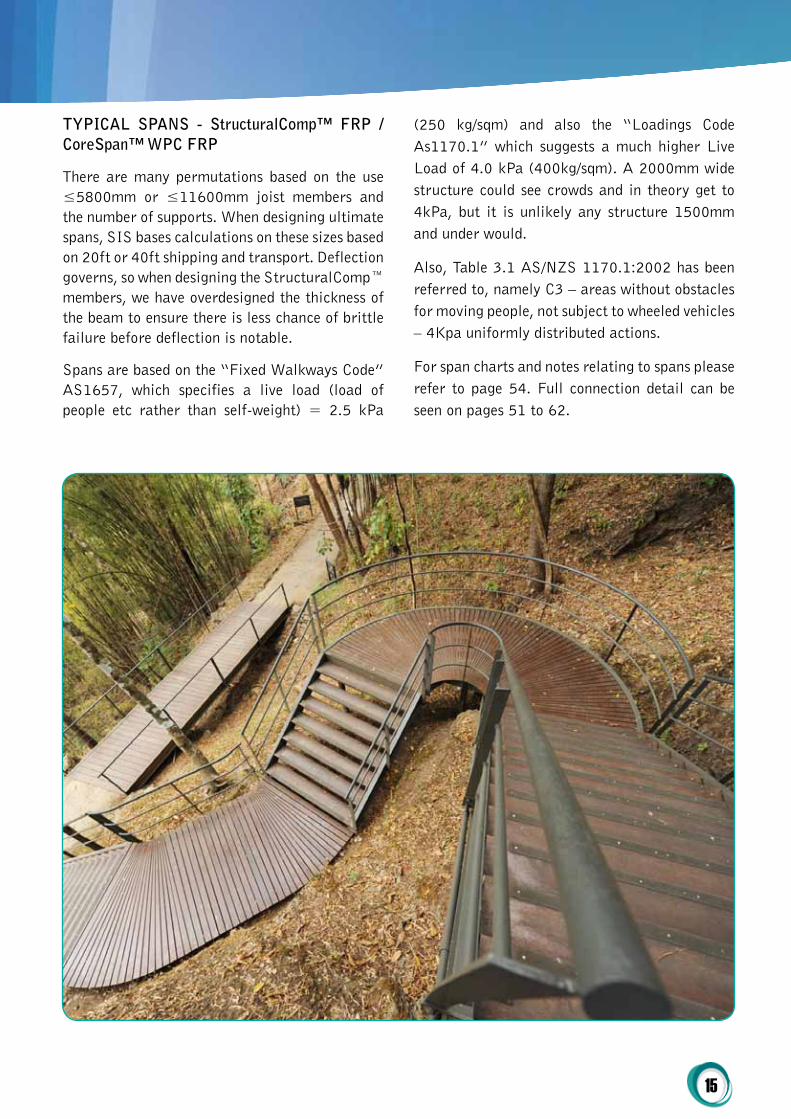
typicAL SpANS - Structuralcomp™ Frp / coreSpan™ Wpc Frp
There are many permutations based on the use ≤5800mm or ≤11600mm joist members and the number of supports. When designing ultimate spans, SIS bases calculations on these sizes based on 20ft or 40ft shipping and transport. Deflection governs, so when designing the StructuralComp™ members, we have overdesigned the thickness of the beam to ensure there is less chance of brittle failure before deflection is notable.
Spans are based on the “Fixed Walkways Code” AS1657, which specifies a live load (load of people etc rather than self-weight) = 2.5 kPa
(250 kg/sqm) and also the “Loadings Code As1170.1” which suggests a much higher Live Load of 4.0 kPa (400kg/sqm). A 2000mm wide structure could see crowds and in theory get to 4kPa, but it is unlikely any structure 1500mm and under would.
Also, Table 3.1 AS/NZS 1170.1:2002 has been referred to, namely C3 – areas without obstacles for moving people, not subject to wheeled vehicles – 4Kpa uniformly distributed actions.
For span charts and notes relating to spans please refer to page 54. Full connection detail can be seen on pages 51 to 62.

16
typicAL coMpoNENt QUANtitiES & MEMBEr cUt LiSt
(For Superstructure Only)
1000mm Wide x 100000mm / (approx) Long / 1000mm from GL / Live Load 4kPa / Point Load
2kN / Joist Members Not Supported with Joist Members ≤5800mm
SISCo-FC™ Component List
Member Member Length Quantity total Meters
StructuralComp™ 120mm x 120mm x 8mm Pile
1800mm 58 104.4
StructuralComp™ 250mm x 125mm x 12mm Bearer
1000mm 29 29
StructuralComp™ 250mm x 125mm x 12mm Joist
3600mm 56 201.6
StructuralComp™ Pile to Bearer Bracket
n/a 58 n/a
StructuralComp™ Bearer to Joist Bracket
n/a 114 n/a
Fig. 5
1000mm Wide x 100000mm (approx) Long / 1000mm from GL / Live Load 4kPa / Point Load 2kN / Joist Members Supported with Joist Members ≤11600mm
SISCo-FC™ Component List
Member Member Length Quantity total Meters
StructuralComp™ 120mm x 120mm x 8mm Pile
1800mm 46 82.8
StructuralComp™ 250mm x 125mm x 12mm Bearer
1000mm 23 23
StructuralComp™ 250mm x 125mm x 12mm Joist
9000mm 22 198
StructuralComp™ Pile to Bearer Bracket
n/a 46 n/a
StructuralComp™ Bearer to Joist Bracket
n/a 44 n/a
Fig. 6
17
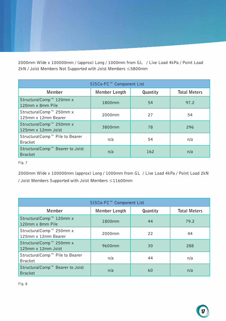
2000mm Wide x 100000mm / (approx) Long / 1000mm from GL / Live Load 4kPa / Point Load 2kN / Joist Members Not Supported with Joist Members ≤5800mm
SISCo-FC™ Component List
Member Member Length Quantity total Meters
StructuralComp™ 120mm x 120mm x 8mm Pile
1800mm 54 97.2
StructuralComp™ 250mm x 125mm x 12mm Bearer
2000mm 27 54
StructuralComp™ 250mm x 125mm x 12mm Joist
3800mm 78 296
StructuralComp™ Pile to Bearer Bracket
n/a 54 n/a
StructuralComp™ Bearer to Joist Bracket
n/a 162 n/a
Fig. 7
2000mm Wide x 100000mm (approx) Long / 1000mm from GL / Live Load 4kPa / Point Load 2kN
/ Joist Members Supported with Joist Members ≤11600mm
SISCo-FC™ Component List
Member Member Length Quantity total Meters
StructuralComp™ 120mm x 120mm x 8mm Pile
1800mm 44 79.2
StructuralComp™ 250mm x 125mm x 12mm Bearer
2000mm 22 44
StructuralComp™ 250mm x 125mm x 12mm Joist
9600mm 30 288
StructuralComp™ Pile to Bearer Bracket
n/a 44 n/a
StructuralComp™ Bearer to Joist Bracket
n/a 60 n/a
Fig. 8

18
Refer Annexure 2 for details on FRP testing
High strength plastics are usually composite plastics, meaning that they are made up of a base resin with the addition of various percentages of fiber. Some of the most common fibers are fiberglass or carbon. Many additives are sometimes mixed in with a plastic to improve its characteristics. For example, additives may cause a plastic to be UV resistant or fire retardant (UL 94 V-0). Some additives change the color of the material. Others lower a plastic´s coefficient of friction to make it suitable for use in bearing applications. While most plastics are thought of as electrical insulators, additives can also make them conductive. While all these additives are useful, the only way to achieve greater strength in plastics is to add fibers.
What does “strong” mean in the world of plastics? how are plastics evaluated for strength?
The strength of a material may be evaluated through the results of several strengh tests. ASTM International® is an international standards organization that develops and publishes voluntary consensus technical standards.* We will consider the results of tests described by their standards for ultimate tensile strength (UTS, tensile modulus (otherwise nown as “Young´s Modulus”) and flexural strength.
• tensile Strength or Ultimate tensile Strength (UtS) is the maximum stress a polymer can withstand without breaking while being pulled or stretched. ASTM D638
• tensile Modulus or young´s Modulus is a numerical constant that describes the elastic properties of a plastic under tension or compression from only one direction. It is a measure of stiffness. ASTM 638
• Flexural Strength is a material´s ability to resist deformation under load for materials that deform significantlly but do not break. Many plastics exhibit flexural strength. This number represents the load required to cause a given test sample to exhibit a 5% deformation ASTM D790
• izod impact Strength (Notched) is a single point test that measures the resistance of a material to impact. The resulting number represents the kinetic energy needed to initiate and cause the fracture of a given notched specimen of material. ASTM D256
*ISO and DIN standards are also used
Plastics Engineered for Strength
19
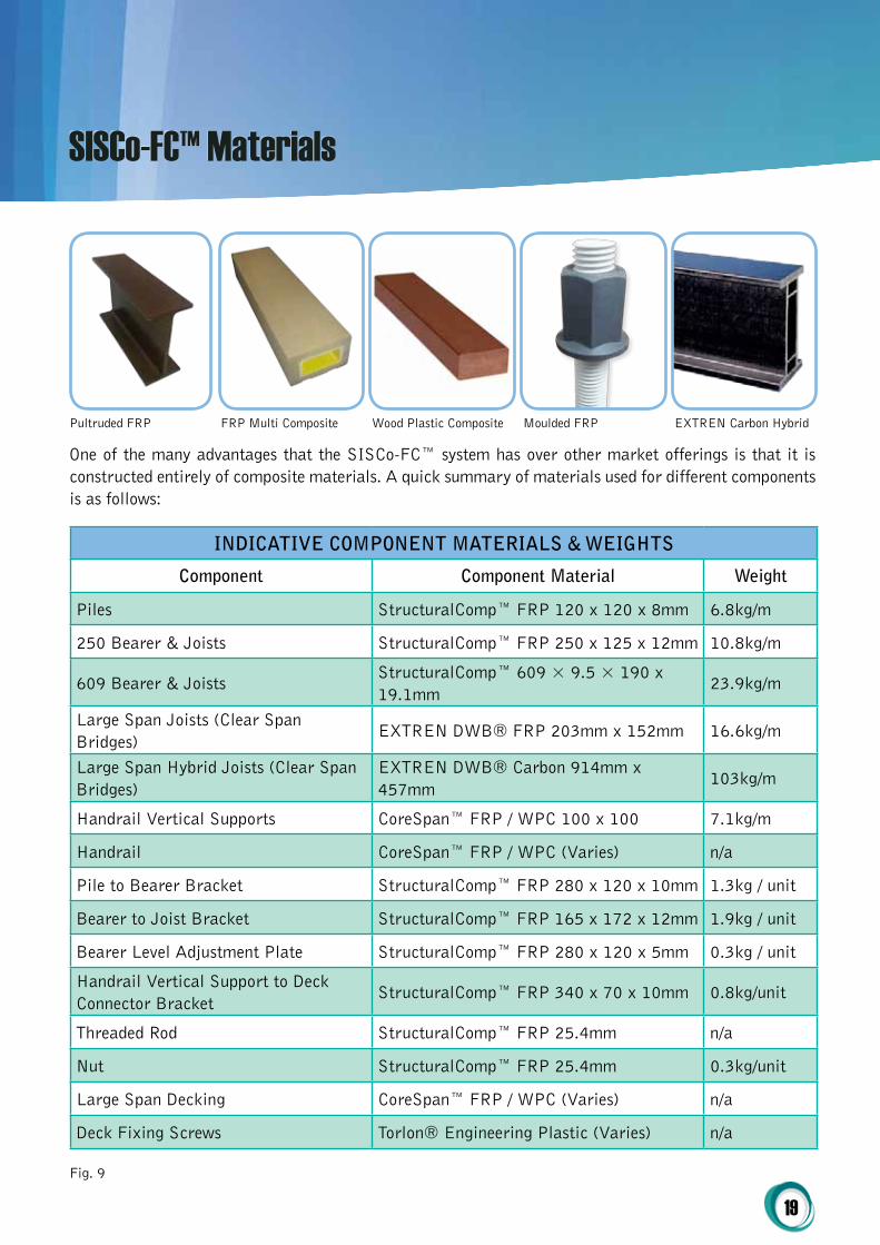
One of the many advantages that the SISCo-FC™ system has over other market offerings is that it is constructed entirely of composite materials. A quick summary of materials used for different components is as follows:
iNDicAtiVE coMpoNENt MAtEriALS & WEightS
component component Material Weight
Piles StructuralComp™ FRP 120 x 120 x 8mm 6.8kg/m
250 Bearer & Joists StructuralComp™ FRP 250 x 125 x 12mm 10.8kg/m
609 Bearer & JoistsStructuralComp™ 609 × 9.5 × 190 x 19.1mm
23.9kg/m
Large Span Joists (Clear Span Bridges)
EXTREN DWB® FRP 203mm x 152mm 16.6kg/m
Large Span Hybrid Joists (Clear Span Bridges)
EXTREN DWB® Carbon 914mm x 457mm
103kg/m
Handrail Vertical Supports CoreSpan™ FRP / WPC 100 x 100 7.1kg/m
Handrail CoreSpan™ FRP / WPC (Varies) n/a
Pile to Bearer Bracket StructuralComp™ FRP 280 x 120 x 10mm 1.3kg / unit
Bearer to Joist Bracket StructuralComp™ FRP 165 x 172 x 12mm 1.9kg / unit
Bearer Level Adjustment Plate StructuralComp™ FRP 280 x 120 x 5mm 0.3kg / unit
Handrail Vertical Support to Deck Connector Bracket
StructuralComp™ FRP 340 x 70 x 10mm 0.8kg/unit
Threaded Rod StructuralComp™ FRP 25.4mm n/a
Nut StructuralComp™ FRP 25.4mm 0.3kg/unit
Large Span Decking CoreSpan™ FRP / WPC (Varies) n/a
Deck Fixing Screws Torlon® Engineering Plastic (Varies) n/a
Fig. 9
Pultruded FRP FRP Multi Composite Wood Plastic Composite Moulded FRP EXTREN Carbon Hybrid
SISCo-FC™ Materials
20
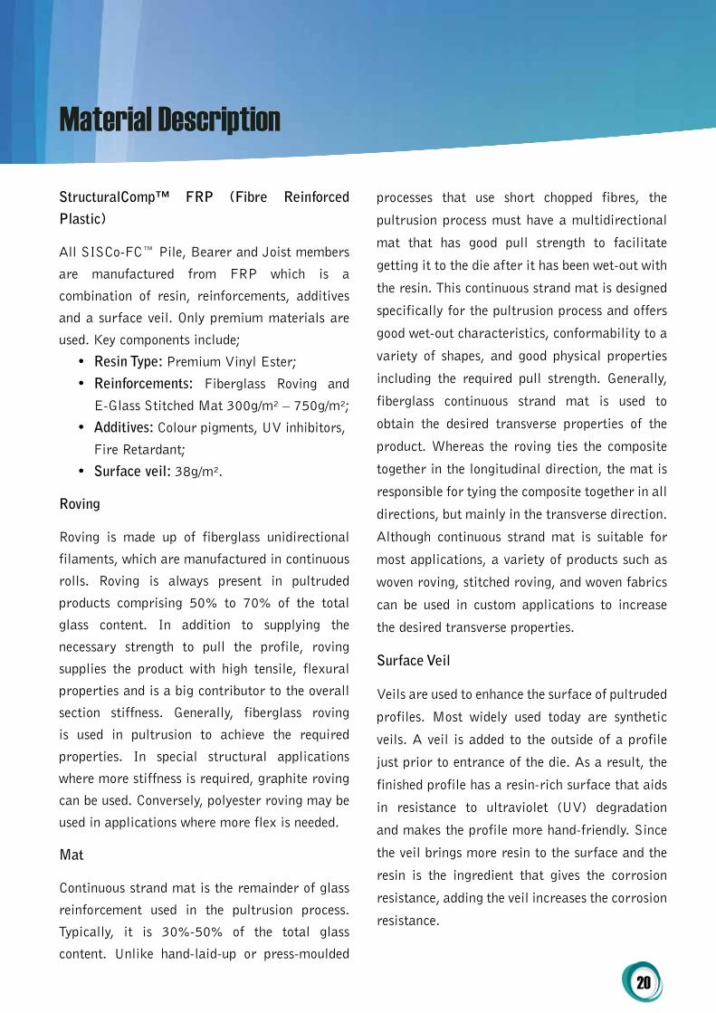
Structuralcomp™ Frp (Fibre reinforced plastic)
All SISCo-FC™ Pile, Bearer and Joist members
are manufactured from FRP which is a
combination of resin, reinforcements, additives
and a surface veil. Only premium materials are
used. Key components include;
• resin type: Premium Vinyl Ester;
• reinforcements: Fiberglass Roving and
E-Glass Stitched Mat 300g/m² – 750g/m²;
• Additives: Colour pigments, UV inhibitors,
Fire Retardant;
• Surface veil: 38g/m².
roving
Roving is made up of fiberglass unidirectional
filaments, which are manufactured in continuous
rolls. Roving is always present in pultruded
products comprising 50% to 70% of the total
glass content. In addition to supplying the
necessary strength to pull the profile, roving
supplies the product with high tensile, flexural
properties and is a big contributor to the overall
section stiffness. Generally, fiberglass roving
is used in pultrusion to achieve the required
properties. In special structural applications
where more stiffness is required, graphite roving
can be used. Conversely, polyester roving may be
used in applications where more flex is needed.
Mat
Continuous strand mat is the remainder of glass
reinforcement used in the pultrusion process.
Typically, it is 30%-50% of the total glass
content. Unlike hand-laid-up or press-moulded
processes that use short chopped fibres, the
pultrusion process must have a multidirectional
mat that has good pull strength to facilitate
getting it to the die after it has been wet-out with
the resin. This continuous strand mat is designed
specifically for the pultrusion process and offers
good wet-out characteristics, conformability to a
variety of shapes, and good physical properties
including the required pull strength. Generally,
fiberglass continuous strand mat is used to
obtain the desired transverse properties of the
product. Whereas the roving ties the composite
together in the longitudinal direction, the mat is
responsible for tying the composite together in all
directions, but mainly in the transverse direction.
Although continuous strand mat is suitable for
most applications, a variety of products such as
woven roving, stitched roving, and woven fabrics
can be used in custom applications to increase
the desired transverse properties.
Surface Veil
Veils are used to enhance the surface of pultruded
profiles. Most widely used today are synthetic
veils. A veil is added to the outside of a profile
just prior to entrance of the die. As a result, the
finished profile has a resin-rich surface that aids
in resistance to ultraviolet (UV) degradation
and makes the profile more hand-friendly. Since
the veil brings more resin to the surface and the
resin is the ingredient that gives the corrosion
resistance, adding the veil increases the corrosion
resistance.
Material Description
21
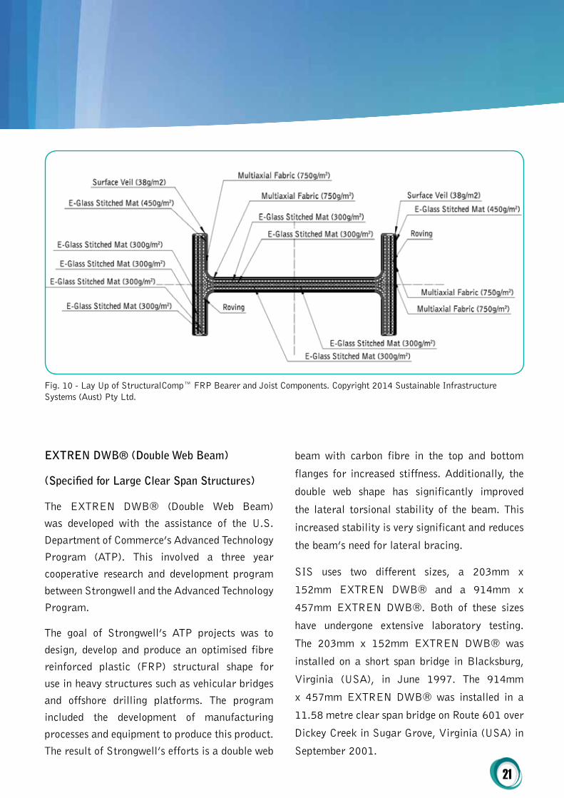
EXtrEN DWB® (Double Web Beam)
(Specified for Large clear Span Structures)
The EXTREN DWB® (Double Web Beam) was developed with the assistance of the U.S. Department of Commerce’s Advanced Technology Program (ATP). This involved a three year cooperative research and development program between Strongwell and the Advanced Technology Program.
The goal of Strongwell’s ATP projects was to design, develop and produce an optimised fibre reinforced plastic (FRP) structural shape for use in heavy structures such as vehicular bridges and offshore drilling platforms. The program included the development of manufacturing processes and equipment to produce this product. The result of Strongwell’s efforts is a double web
beam with carbon fibre in the top and bottom
flanges for increased stiffness. Additionally, the
double web shape has significantly improved
the lateral torsional stability of the beam. This
increased stability is very significant and reduces
the beam’s need for lateral bracing.
SIS uses two different sizes, a 203mm x
152mm EXTREN DWB® and a 914mm x
457mm EXTREN DWB®. Both of these sizes
have undergone extensive laboratory testing.
The 203mm x 152mm EXTREN DWB® was
installed on a short span bridge in Blacksburg,
Virginia (USA), in June 1997. The 914mm
x 457mm EXTREN DWB® was installed in a
11.58 metre clear span bridge on Route 601 over
Dickey Creek in Sugar Grove, Virginia (USA) in
September 2001.
Fig. 10 - Lay Up of StructuralComp™ FRP Bearer and Joist Components. Copyright 2014 Sustainable Infrastructure Systems (Aust) Pty Ltd.
22
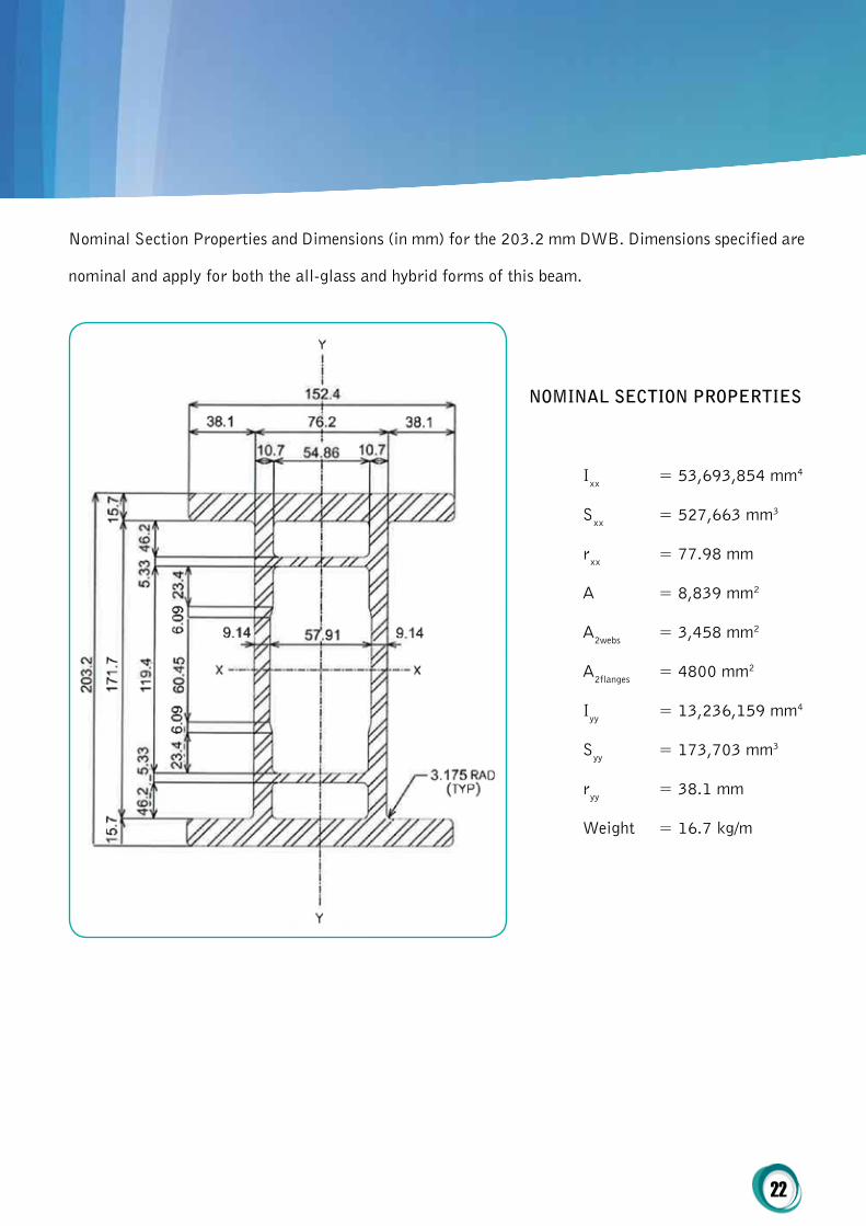
Nominal Section Properties and Dimensions (in mm) for the 203.2 mm DWB. Dimensions specified are
nominal and apply for both the all-glass and hybrid forms of this beam.
NoMiNAL SEctioN propErtiES
Ixx = 53,693,854 mm4
Sxx = 527,663 mm3
rxx = 77.98 mm
A = 8,839 mm2
A2webs = 3,458 mm2
A2flanges = 4800 mm2
Iyy = 13,236,159 mm4
Syy = 173,703 mm3
ryy = 38.1 mm
Weight = 16.7 kg/m

23
Nominal Section Properties and Dimensions (in mm) for the 914.4 mm DWB.
NoMiNAL SEctioN propErtiES
Ixx = 6.36 x 109 mm4
Sxx = 13,912,617 mm3
rxx = 327.6 mm
A = 58,839 mm2
A2webs = 32,323 mm2
A2flanges = 21,935 mm2
Iyy = 1.09 x 109 mm4
Syy = 4,785,023 mm3
ryy = 136.4 mm
Weight = 104.2 kg/m

24
The EXTREN DWB® design data are the result of extensive testing and evaluation by two engineering departments of Virginia Tech – the Via Department of Civil & Environmental Engineering and the Department of Engineering Sciences and Mechanics. The availability of Virginia Tech’s heavy structures laboratory and the recognised expertise of its engineering professors provided an independent third party evaluation of the EXTREN DWB®. Strongwell’s mechanical testing laboratory has also created a database of coupon test properties for the EXTREN DWB® structural shape. This database enables Strongwell to compare the coupon properties of each manufactured lot of EXTREN DWB® shapes and to certify that each lot meets the performance characteristics and criteria identified in the design guide. Strongwell’s certification of these properties provides structural engineers with the confidence that EXTREN DWB® structural shapes meet the performance requirements specified.
203mm x 152mm EXtrEN DWB® - ALL-gLASS
The 203mm x 152mm EXTREN DWB®, all-glass beam, is a pultruded structural shape composed of four different types of E-glass reinforcements in a vinyl ester resin matrix. The all-glass laminate includes 0° longitudinal rovings, continuous strand mat, 0°/90° stitched fabric, and ±45° stitched fabric. The approximate fibre volume fraction is 55%. The DWB shape improves the apparent (or effective) modulus of elasticity and the stability of the structure under load versus traditional FRP WF or I shapes.
203mm x 152mm EXtrEN DWB® - hyBriD BEAM
The 203mm x 152mm EXTREN DWB®, hybrid beam, is a pultruded structural shape composed of carbon fibre tows and four different types of glass reinforcements in a vinyl ester resin matrix. The 0° carbon tows replace some of the 0° glass rovings in the top and bottom flanges of the shape. The remainder of the laminate is identical to the all-glass beam. The carbon tows improve the apparent (or effective) modulus of elasticity at least 30% versus the all-glass beam. The approximate fibre volume is 55% (including glass and carbon).
914mm x 457mm EXtrEN DWB® - hyBriD BEAM
The 914mm x 457mm EXTREN DWB® is only produced as a hybrid beam. It is a pultruded structural shape composed of carbon fibre tows in the top and bottom flanges and the same four types of E-glass reinforcements as the 914mm x 457mm in a vinyl ester resin matrix throughout the entire structural shape. The carbon tows improve the apparent (or effective) modulus of elasticity. The approximate fibre volume is 55% (including glass and carbon) and the shape weighs 104 kg’s per metre. The 914mm x 457mm EXTREN DWB® was specifically designed for use in vehicular bridges.
corESpANtM Wood plastic composite / Fibre reinforced plastic composite Multi Extrusion
The denomination ‘wood-plastic composites’, WPC, is used to designate materials or products made of one or more natural fibres or flours and a polymer or a mixture of polymers. SIS’s choice of natural fibres and flours come from wood and

25
our polymers (recycled) are polypropylene (PP) and polyethylene (PE).
SIS’s research and development into WPC ingredients, manufacturing processes and products is always ongoing, it is false to assume that it is just waste wood and a kind of polymer mixed together and pressed through an extrusion die or into the cavity of an injection mould. Our innovative, state of the art WPC compounds are well advanced. We have a large investment in intellectual property associated with wood conditioning, treatment, stabilization of various polymers as well as crucial additives and processing. Our composite formula’s brings together the best qualities of wood and plastic to create a superior alternative to wood:
• Plastic shields the wood from moisture and insect damage, preventing rotting and splintering;
• Wood protects the plastic from UV damage while providing a natural, attractive look and feel.
The result is sustainable timber alternative products that require only periodic cleaning to remain sound for many years, therefore eliminating the need for sanding, staining or painting. It will not rot or deteriorate due to harsh weather or insects and is splinter-free and has excellent traction, even when wet. It contains no toxic chemicals or preservatives. WPC resists damage from moisture and sunlight, making it the natural choice for aquatic and marine environments.
Frp (Fibre reinforced plastic) Fr-4/g10 – threaded rods
FR-4 is again a composite material made up of
woven fiberglass cloth and an epoxy resin. This combination gives the laminate good strength to weight ratios. Typical physical and electrical properties of FR-4 are expressed by LW (length wise, wrap yarn direction), and CW (cross wise, fill yarn direction). LW and CW refer to fibre orientations that are perpendicular to each other.
StructuralComp™ FRP FR-4 plastic fasteners are flame resistant. Flame resistant means that the parts are self- extinguishing. With near zero water absorption, FR-4 plastic fasteners retain their high mechanical strength and electrical insulating qualities in both dry and humid condition
torlon® (pAi)-torlon® polyamide-imide (pAi) – Deck to Joist Fasteners
Torlon® is a high strength plastic with the highest strength and stiffness of any plastic up to 275°C (525°F). It has outstanding resistance to wear, creep, and chemicals, including strong acids and most organic chemicals, and is ideally suited for severe service environments.
Torlon is typically used to make aircraft hardware and fasteners, mechanical and structural components, transmission and power train components and is the chosen material for deck to joist fixings in the SISCo-FC™ System.
typicAL propErtiES oF Frp thrEADED roD / NUtS
StructuralComp™ threaded rod and nuts are manufactured using premium vinyl-ester resin containing UV inhibitors. The properties listed on the following page are the result of the ASTM test method indicated.

26
properties of Structuralcomp™ Frp threaded rod
properties AStM Units Value 19.0mm 25.4mm
Ultimate Transverse Shear B-565 (Double Shear) - NM 59,600 106,750
Longitudinal Compressive Strength D-695 MPa 344 344
Flexural Strength D-790 MPa 482 482
Flexural Modulus D-790 GPa 17.2 17.2
Water Absorption (24 hr. immersion) D-570 - % Max 0.8 0.8
Longitudinal Coefficient of Thermal Expansion D-696 10-6 mm/mm/°C 11 11
Ultimate Thread Shear Using FRP Nut - NM 17,790 36,470
Ultimate Torque Strength fibreglass nut lubricated with SAE 10W30 motor oil - NM
67 149
Rod Weight - Kg/m 0.447 0.789
Nut Weight - Grams 27.2 63.6
Nut Dimensions – mm. (square) x mm. (thick) 31.5 x 20.8 41.4 x 27.9
Fig. 12
connection Fixings tensile Strength property comparison
tensile Strength property comparison
Material Mpa PSI
FR-4 310 44,960
PARA (50% glass-filled) 230 33,358
TPU (40% glass-filled) 186 29,977
Magnesium 225 32,633
Brass 250 36,259
Zinc Alloy 280 40,610
Aluminum (6061-0 Temper) 125 18,000
Steel 330 47,862
Fig. 11
27
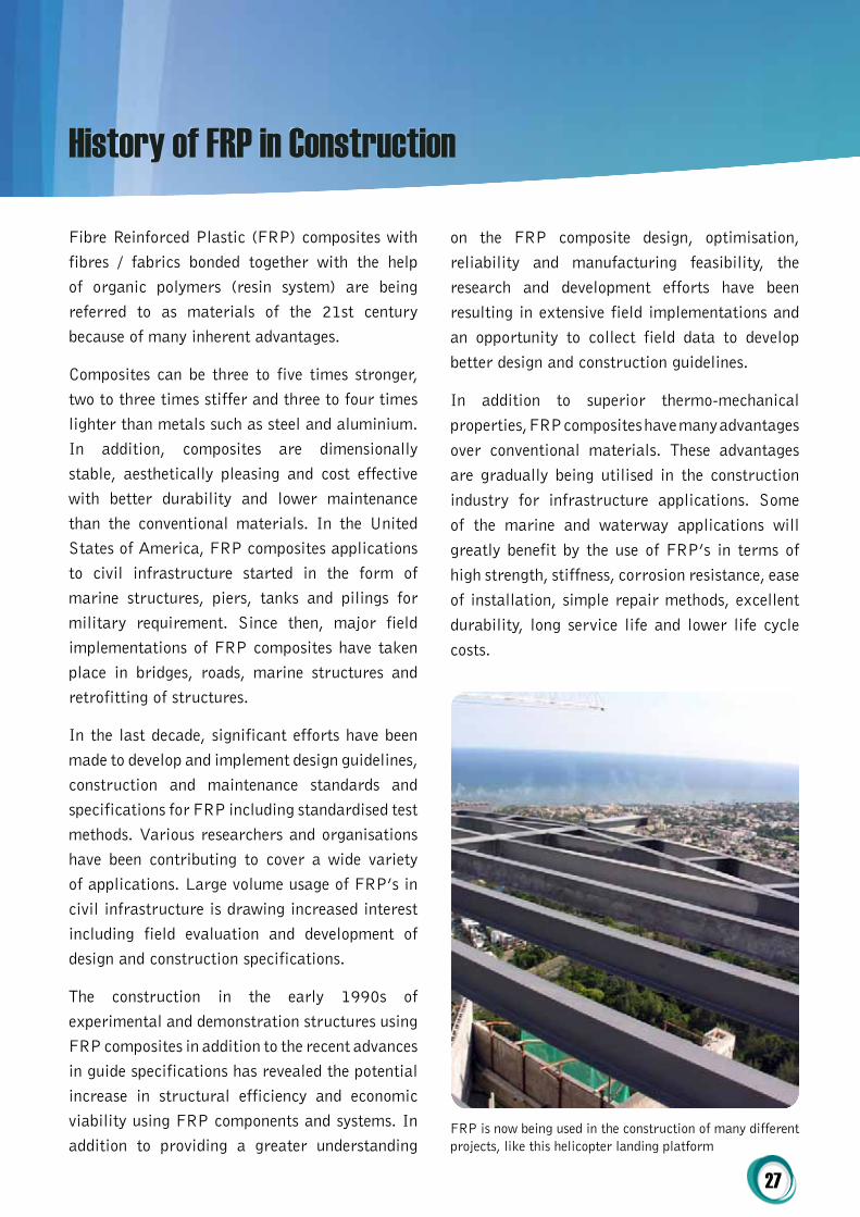
Fibre Reinforced Plastic (FRP) composites with fibres / fabrics bonded together with the help of organic polymers (resin system) are being referred to as materials of the 21st century because of many inherent advantages.
Composites can be three to five times stronger, two to three times stiffer and three to four times lighter than metals such as steel and aluminium. In addition, composites are dimensionally stable, aesthetically pleasing and cost effective with better durability and lower maintenance than the conventional materials. In the United States of America, FRP composites applications to civil infrastructure started in the form of marine structures, piers, tanks and pilings for military requirement. Since then, major field implementations of FRP composites have taken place in bridges, roads, marine structures and retrofitting of structures.
In the last decade, significant efforts have been made to develop and implement design guidelines, construction and maintenance standards and specifications for FRP including standardised test methods. Various researchers and organisations have been contributing to cover a wide variety of applications. Large volume usage of FRP’s in civil infrastructure is drawing increased interest including field evaluation and development of design and construction specifications.
The construction in the early 1990s of experimental and demonstration structures using FRP composites in addition to the recent advances in guide specifications has revealed the potential increase in structural efficiency and economic viability using FRP components and systems. In addition to providing a greater understanding
on the FRP composite design, optimisation, reliability and manufacturing feasibility, the research and development efforts have been resulting in extensive field implementations and an opportunity to collect field data to develop better design and construction guidelines.
In addition to superior thermo-mechanical properties, FRP composites have many advantages over conventional materials. These advantages are gradually being utilised in the construction industry for infrastructure applications. Some of the marine and waterway applications will greatly benefit by the use of FRP’s in terms of high strength, stiffness, corrosion resistance, ease of installation, simple repair methods, excellent durability, long service life and lower life cycle costs.
FRP is now being used in the construction of many different projects, like this helicopter landing platform
History of FRP in Construction

28
LiFEcycLE coStS – tiMBEr vs. Structuralcomp™ Frp
Timbe
r stru
cture
s
SISCo-FC™ Systems
252015Years
105 00
Break-evenin 6 years
Rel
ativ
e co
sts
SISCo-FC™ Systems cost far less during the lifetime of a structure because they need little if any maintenance.Real comparisons with timber structures show the break-even point is just six years, sometimes far less.Fig. 13 - SISCo-FCTM Systems cost far less during the lifetime of a structure because they need little if any maintenance.
Real comparisons with timber structures show the break-even point is just six years, sometimes far less. Copyright 2014 Sustainable Infrastructure Systems (Aust) Pty Ltd
Don’t Let this happen to you
The Cape Cod National Seashore’s Red Maple Swamp Trail, a winding boardwalk that meanders just inches above water most of the year, is a popular destination for walkers in all seasons. But when sections of the boardwalk collapsed due to rotting timber posts, park officials had to close it and now are waiting for word on whether they will get the $200,000 for repairs. Although the park resurfaced the structure over 12 years ago with recycled plastic decking, there wasn’t money to replace the timber posts and beams that support the walkway, hence now the collapse.
29
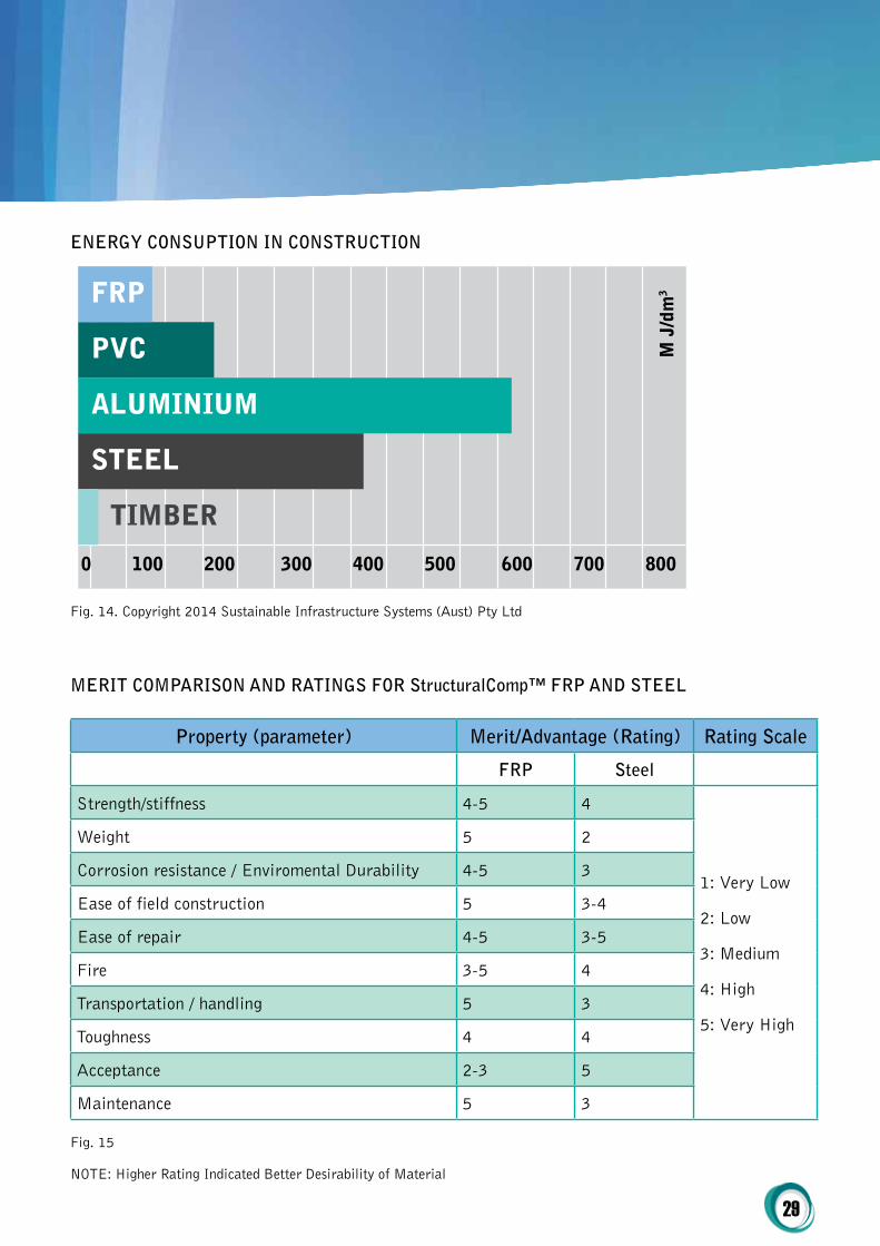
ENErgy coNSUptioN iN coNStrUctioN
Fig. 14. Copyright 2014 Sustainable Infrastructure Systems (Aust) Pty Ltd
MErit coMpAriSoN AND rAtiNgS For Structuralcomp™ Frp AND StEEL
property (parameter) Merit/Advantage (rating) rating Scale
Frp Steel
Strength/stiffness 4-5 4
1: Very Low
2: Low
3: Medium
4: High
5: Very High
Weight 5 2
Corrosion resistance / Enviromental Durability 4-5 3
Ease of field construction 5 3-4
Ease of repair 4-5 3-5
Fire 3-5 4
Transportation / handling 5 3
Toughness 4 4
Acceptance 2-3 5
Maintenance 5 3
Fig. 15
NOTE: Higher Rating Indicated Better Desirability of Material
FRP
PVC
ALUMINIUM
STEEL
TIMBER
0 100 200 300 400 500 600 700 800
M J
/dm
3
30
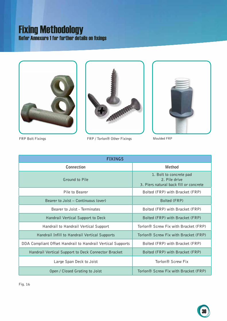
FiXiNgS
connection Method
Ground to Pile1. Bolt to concrete pad
2. Pile drive3. Piers natural back fill or concrete
Pile to Bearer Bolted (FRP) with Bracket (FRP)
Bearer to Joist – Continuous (over) Bolted (FRP)
Bearer to Joist - Terminates Bolted (FRP) with Bracket (FRP)
Handrail Vertical Support to Deck Bolted (FRP) with Bracket (FRP)
Handrail to Handrail Vertical Support Torlon® Screw Fix with Bracket (FRP)
Handrail Infill to Handrail Vertical Supports Torlon® Screw Fix with Bracket (FRP)
DDA Compliant Offset Handrail to Handrail Vertical Supports Bolted (FRP) with Bracket (FRP)
Handrail Vertical Support to Deck Connector Bracket Bolted (FRP) with Bracket (FRP)
Large Span Deck to Joist Torlon® Screw Fix
Open / Closed Grating to Joist Torlon® Screw Fix with Bracket (FRP)
Fig. 16
Fixing Methodology Refer Annexure 1 for further details on fixings
FRP Bolt Fixings FRP / Torlon® Other Fixings Moulded FRP
31
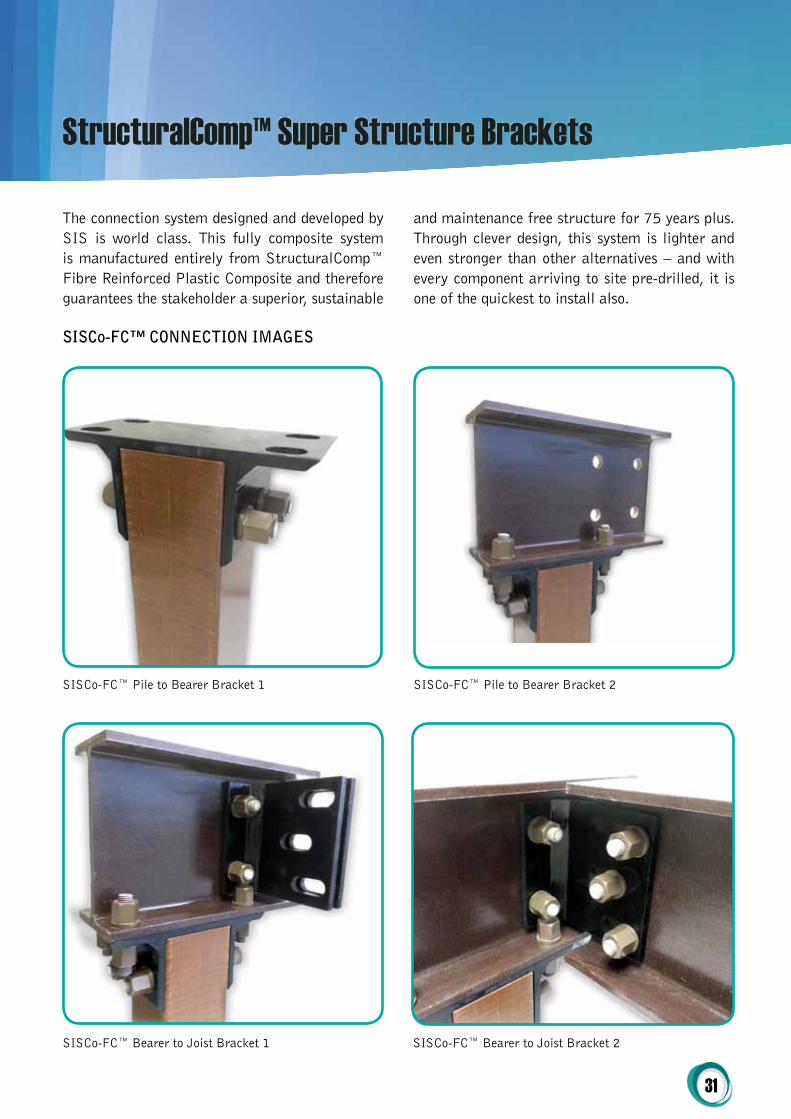
The connection system designed and developed by SIS is world class. This fully composite system is manufactured entirely from StructuralComp™ Fibre Reinforced Plastic Composite and therefore guarantees the stakeholder a superior, sustainable
and maintenance free structure for 75 years plus. Through clever design, this system is lighter and even stronger than other alternatives – and with every component arriving to site pre-drilled, it is one of the quickest to install also.
SISCo-FC™ Pile to Bearer Bracket 1 SISCo-FC™ Pile to Bearer Bracket 2
SISCo-FC™ Bearer to Joist Bracket 1 SISCo-FC™ Bearer to Joist Bracket 2
SiSco-Fc™ coNNEctioN iMAgES
StructuralComp™ Super Structure Brackets
32
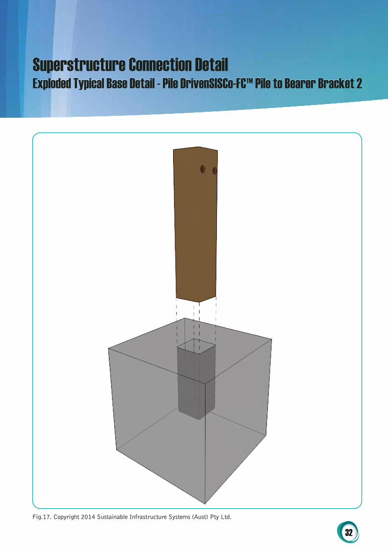
Superstructure Connection DetailExploded Typical Base Detail - Pile DrivenSISCo-FC™ Pile to Bearer Bracket 2
Fig.17. Copyright 2014 Sustainable Infrastructure Systems (Aust) Pty Ltd.

33
Fig. 18. Copyright 2014 Sustainable Infrastructure Systems (Aust) Pty Ltd.
Typical Base Detail - Pile Driven
34
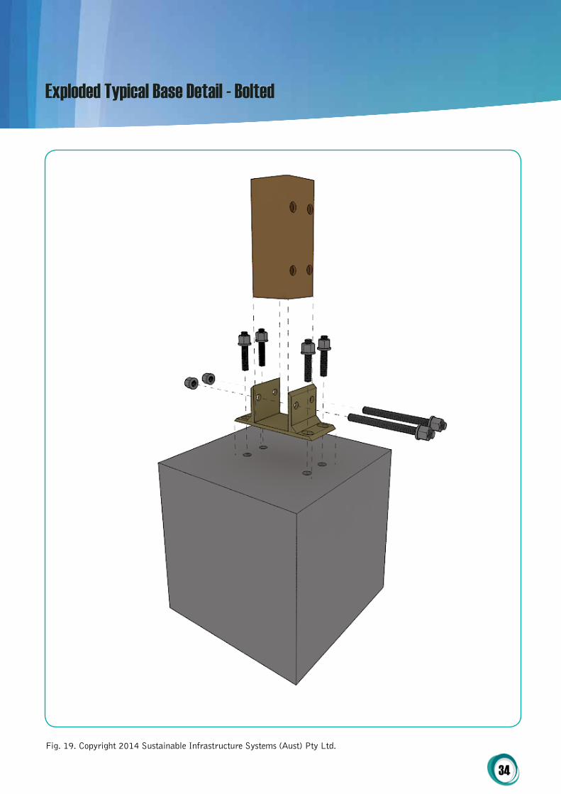
Fig. 19. Copyright 2014 Sustainable Infrastructure Systems (Aust) Pty Ltd.
Exploded Typical Base Detail - Bolted

35
Fig. 20. Copyright 2014 Sustainable Infrastructure Systems (Aust) Pty Ltd.
Exploded Typical Base Detail - Bolted

36
Fig. 21. Copyright 2014 Sustainable Infrastructure Systems (Aust) Pty Ltd.
Exploded Typical Pile to Bearer Detail

37
Fig. 22. Copyright 2014 Sustainable Infrastructure Systems (Aust) Pty Ltd.
Typical Pile to Bearer Detail

38
Fig. 23. Copyright 2014 Sustainable Infrastructure Systems (Aust) Pty Ltd.
Exploded Typical Bearer to Joist
39
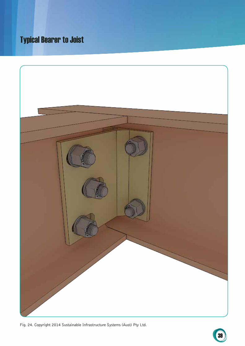
Fig. 24. Copyright 2014 Sustainable Infrastructure Systems (Aust) Pty Ltd.
Typical Bearer to Joist

40
Fig. 25. Copyright 2014 Sustainable Infrastructure Systems (Aust) Pty Ltd.
Exploded Typical Joist over Bearer

41
Fig. 26. Copyright 2014 Sustainable Infrastructure Systems (Aust) Pty Ltd.
Typical Joist over Bearer
42
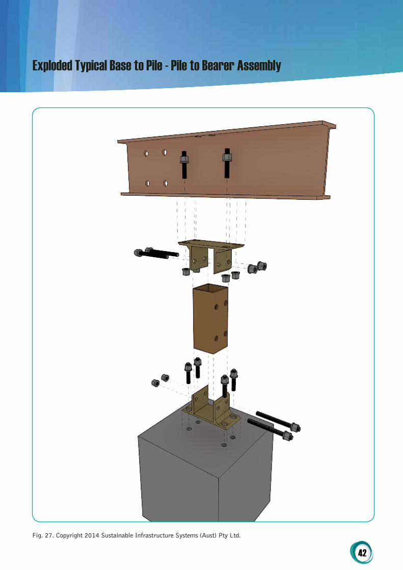
Fig. 27. Copyright 2014 Sustainable Infrastructure Systems (Aust) Pty Ltd.
Exploded Typical Base to Pile - Pile to Bearer Assembly

43
Fig. 28. Copyright 2014 Sustainable Infrastructure Systems (Aust) Pty Ltd.
Exploded Typical Assembly

44
Fig. 29. Copyright 2014 Sustainable Infrastructure Systems (Aust) Pty Ltd.
Typical Assembly
45
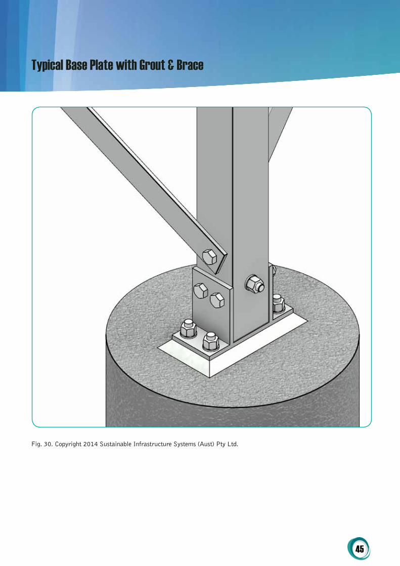
Typical Base Plate with Grout & Brace
Fig. 30. Copyright 2014 Sustainable Infrastructure Systems (Aust) Pty Ltd.

46
Typical Cap Plate & Brace
Fig. 31. Copyright 2014 Sustainable Infrastructure Systems (Aust) Pty Ltd.

47
Typical Handrail Stanchion Connection
Fig. 32. Copyright 2014 Sustainable Infrastructure Systems (Aust) Pty Ltd.
48
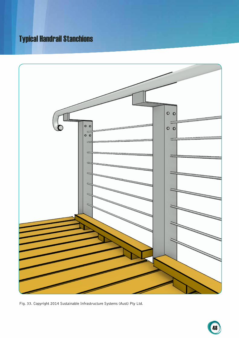
Typical Handrail Stanchions
Fig. 33. Copyright 2014 Sustainable Infrastructure Systems (Aust) Pty Ltd.

49
Typical Bridge Abutment
Fig. 34. Copyright 2014 Sustainable Infrastructure Systems (Aust) Pty Ltd.
50
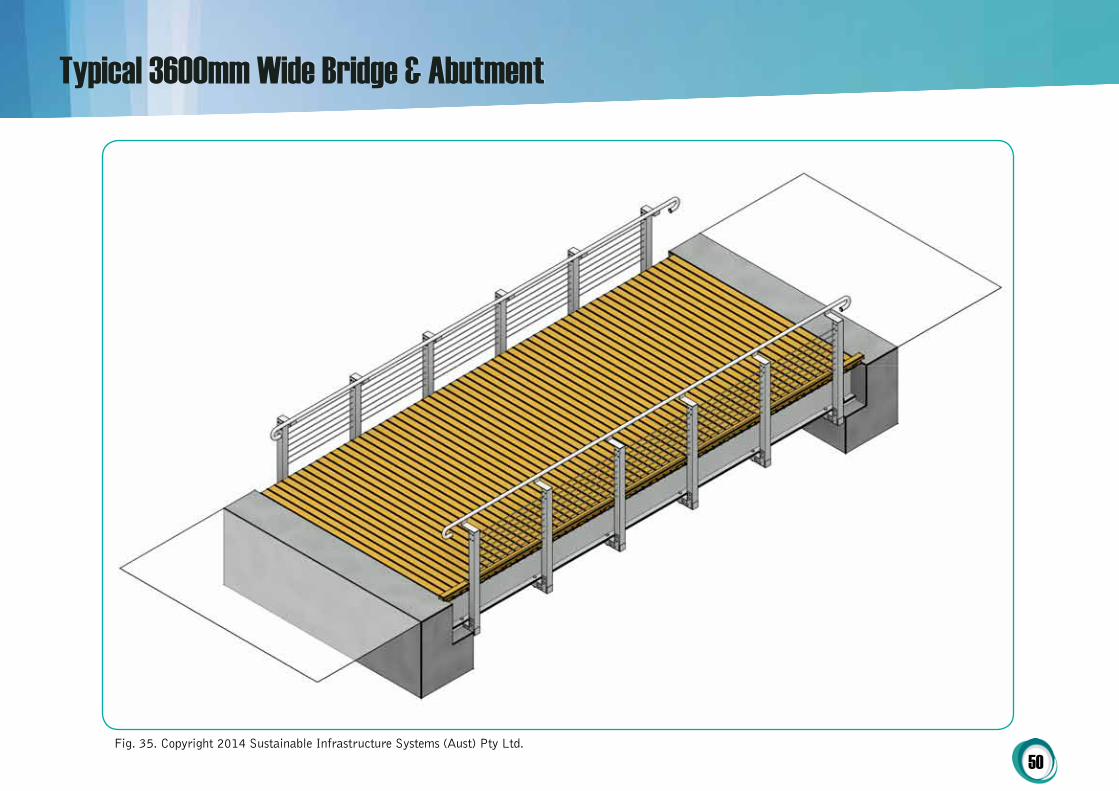
Typical 3600mm Wide Bridge & Abutment
Fig. 35. Copyright 2014 Sustainable Infrastructure Systems (Aust) Pty Ltd.

51
Typical 3600mm Wide Boardwalk Section
Fig. 36. Copyright 2014 Sustainable Infrastructure Systems (Aust) Pty Ltd.

52
Typical 1800mm Wide Boardwalk Section
Fig. 37. Copyright 2014 Sustainable Infrastructure Systems (Aust) Pty Ltd.

53
P6PLANS, SECTIONS & DETAILS
S00150 50104 01
SISCO-FC SYSTEM
App
Project Ref
Sheet
Scale
Drawn
DesignedProject Director Approved Date
COPYRIGHT All rights reserved.These drawings, plans and specifications and the copyright therein are the property of the BonacciGroup and must not be used, reproduced or copied wholly or in part without the written permissionof the Bonacci Group.
ByDateDescriptionRev
North
Drawing No RevDate
Project
Drawing
Name
Title
File
: G:\J
ob\5
0501
04\0
1\_S
truc\
5050
1040
1S-S
001.
dwg
Plo
tted:
02.
04.1
4 at
12:
02 P
M B
y: M
icha
el H
anna
y
ABN 61 160 899 7036 / 7-9 Streiff Road, Wingfield SA 5013Tel: 1300 261 074 Fax: 1300 081 075www.sisau.com.au
Sustainable InfrastructureSystems
TM
Typical Detail
Fig. 38. Copyright 2014 Sustainable Infrastructure Systems (Aust) Pty Ltd.

54
Typical Detail
Fig. 39. Copyright 2014 Sustainable Infrastructure Systems (Aust) Pty Ltd.
55
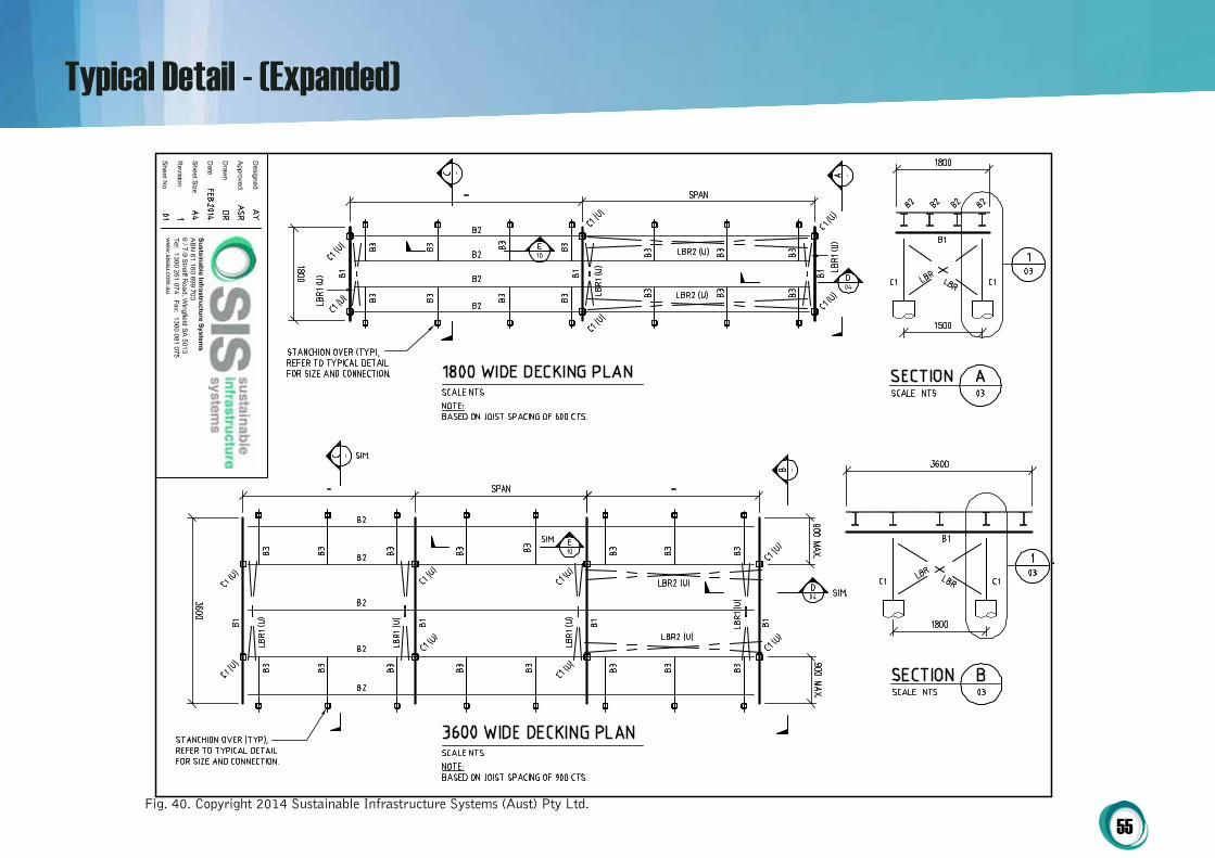
Typical Detail - (Expanded)
Fig. 40. Copyright 2014 Sustainable Infrastructure Systems (Aust) Pty Ltd.

56
Sheet Size
Drawn
Designed
Date
Revision
Approved
Sheet No
Sustainable Infrastructure SystemsABN 61 160 899 7036 / 7-9 Streiff Road, Wingfield SA 5013Tel: 1300 261 074 Fax: 1300 081 075www.sisau.com.au
Typical Detail - (Expanded)
Fig. 41. Copyright 2014 Sustainable Infrastructure Systems (Aust) Pty Ltd.
57
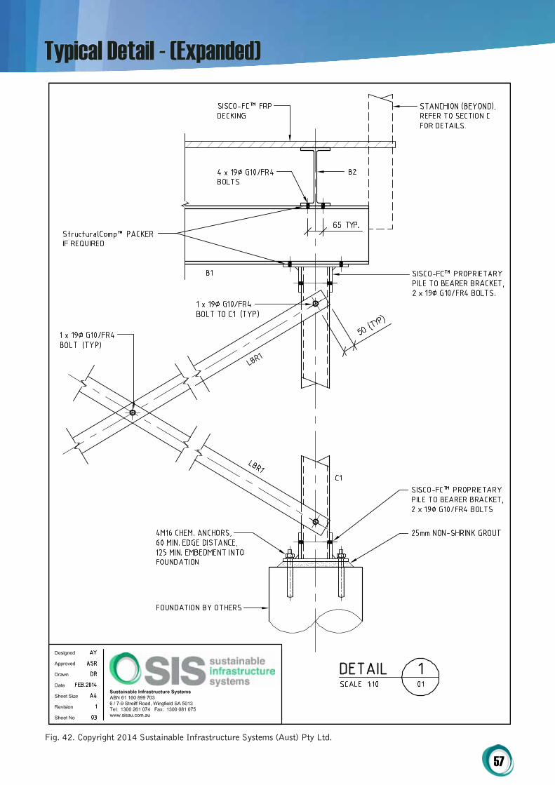
Typical Detail - (Expanded)
Fig. 42. Copyright 2014 Sustainable Infrastructure Systems (Aust) Pty Ltd.
58
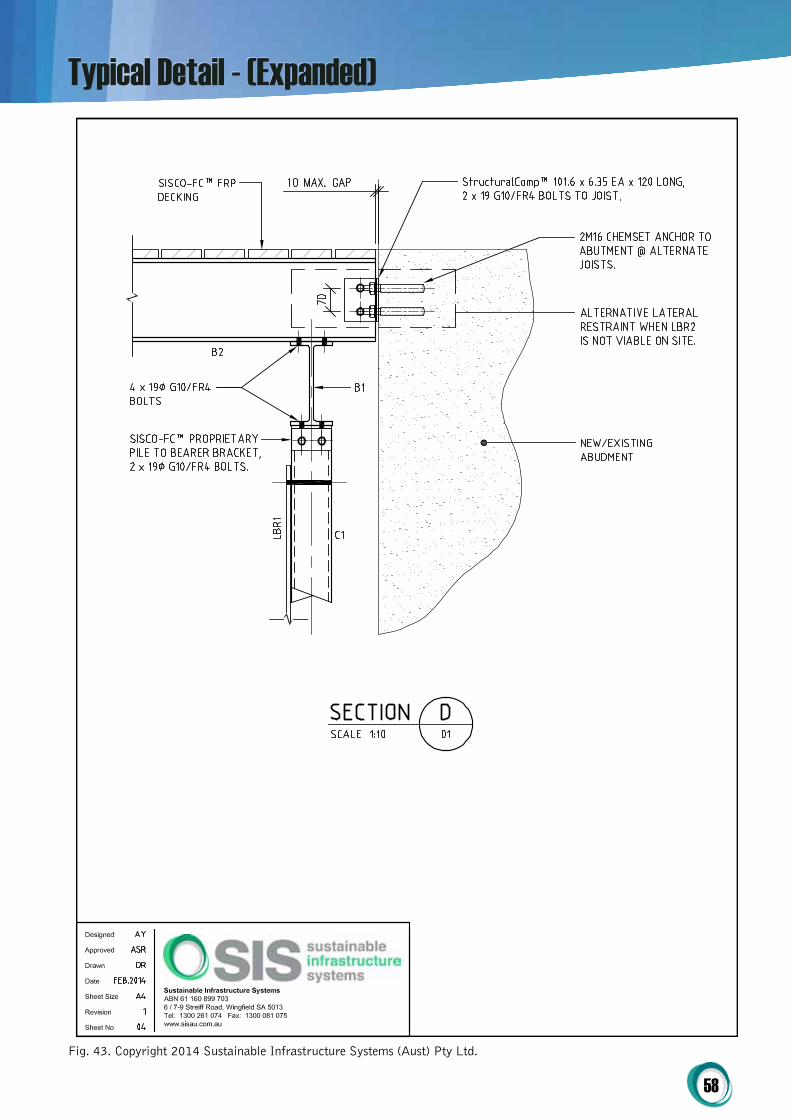
Typical Detail - (Expanded)
Fig. 43. Copyright 2014 Sustainable Infrastructure Systems (Aust) Pty Ltd.
59
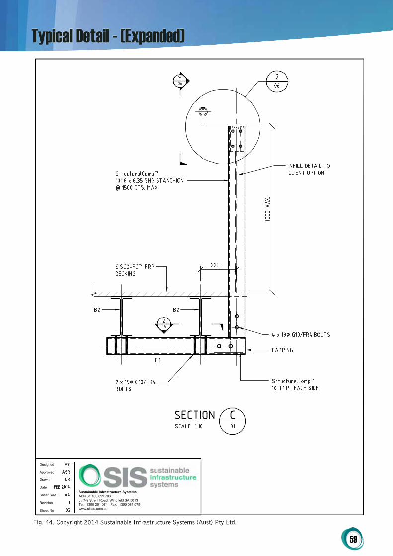
Typical Detail - (Expanded)
Fig. 44. Copyright 2014 Sustainable Infrastructure Systems (Aust) Pty Ltd.

60
Typical Detail - (Expanded)
Fig. 45. Copyright 2014 Sustainable Infrastructure Systems (Aust) Pty Ltd.
61
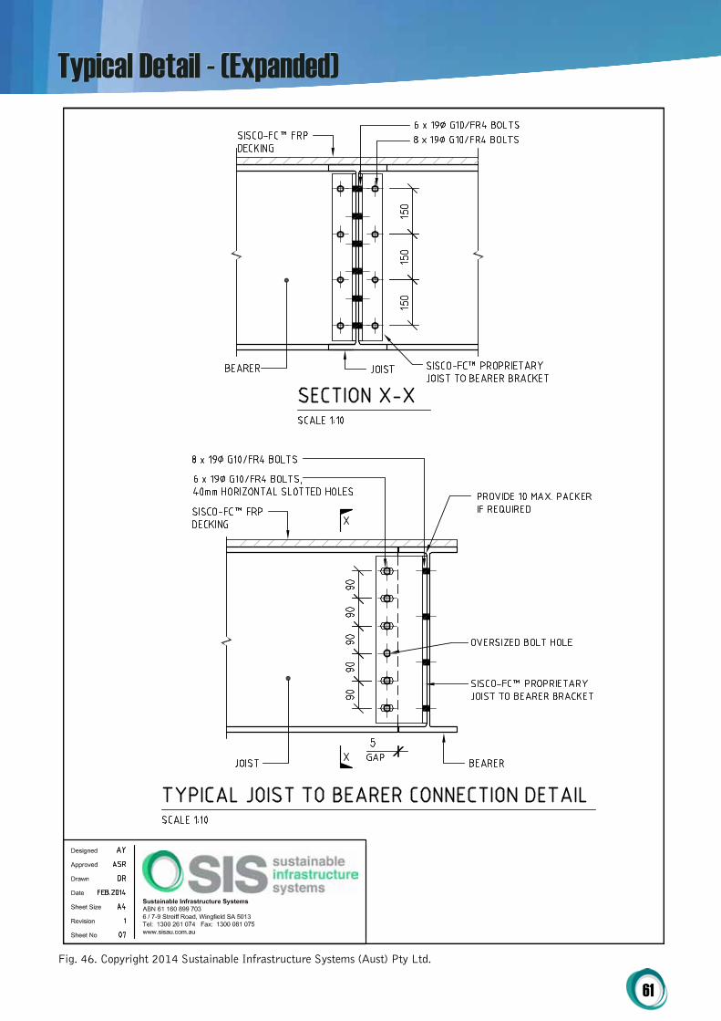
Typical Detail - (Expanded)
Fig. 46. Copyright 2014 Sustainable Infrastructure Systems (Aust) Pty Ltd.

62
Typical Detail - (Expanded)
Fig. 47. Copyright 2014 Sustainable Infrastructure Systems (Aust) Pty Ltd.

63
Typical Detail - (Expanded)
Fig. 48. Copyright 2014 Sustainable Infrastructure Systems (Aust) Pty Ltd.

64
Typical Detail - (Expanded)
Fig. 49. Copyright 2014 Sustainable Infrastructure Systems (Aust) Pty Ltd.

65
SISCo-FC™ WPC Decking / FRP Decking & Grating Options
Structuralcomp™ Frp grAtiNg – colour options
FiBrE rEiNForcED pLAStic coMpoSitE grAtiNg – coLoUr optioNS
Dark GreyStandard
GreyLight Grey Blue Green Yellow Orange
Fig. 48
Structuralcomp™ Frp grAtiNg – Surface options
FiBrE rEiNForcED pLAStic coMpoSitE grAtiNg – SUrFAcE optioNS
Smooth Cover Pool Grit
Checker Plate Cover Meniscus
Grit Cover Grit
Anti Abrasive Grit Smooth
Fig. 50

66
grAtiNg optioN 1
Weight (kg/m²) Web Thickness Void Ratio (%)
21.2 8mm 78
Panel Size Options (WxL) Mesh Size Height
1220mm x 3660mm1220mm x 2440mm915mm x 3050mm
50 x 50mm 50mm
concentrated point Load & Deflection Data – open (Without top)
Load (kg)
Span (mm)
450 600 750 900 1050 1200 1500 1800 2100 2400 2700
Deflection (mm)
150 0.30 0.55 0.80 1.23 1.81 2.62 4.45 7.52 11.47 15.28 23.00
200 0.39 0.73 1.08 1.59 2.40 3.45 5.87 9.75 15.27 21.86
250 0.48 0.87 1.29 2.00 3.08 4.30 7.44 12.17 19.27
300 0.55 1.06 1.54 2.39 3.66 5.16 8.84 14.83
400 0.72 1.37 2.06 3.25 4.85 6.86 11.72
600 1.07 1.99 3.11 4.80 7.22 10.19
800 1.38 2.65 4.14 6.48 9.55
1000 1.70 3.34 4.95 7.60
concentrated point Load & Deflection Data – closed (With 3mm top)
Load (kg)
Span (mm)
600 750 900 1100 1200 1500 1800 2100 2400 2700
Deflection (mm)
100 0.36 0.53 0.65 0.79 1.01 1.98 2.97 4.42 6.63 9.58
150 0.55 0.83 1.03 1.18 1.56 2.99 4.59 6.67 10.17 14.52
200 0.67 1.05 1.30 1.64 2.02 4.07 6.08 9.06 13.79
250 0.78 1.26 1.60 2.04 2.50 4.92 7.77 11.32
300 0.89 1.45 1.91 2.42 3.01 5.89 9.39
400 1.09 1.78 2.40 3.17 3.89 7.79 12.55
600 1.46 2.48 3.39 4.59 5.77 11.60
800 1.84 3.21 4.35 5.99 7.55
Fig. 51
StructuralComp™ FRP Grating – Profile Options
67
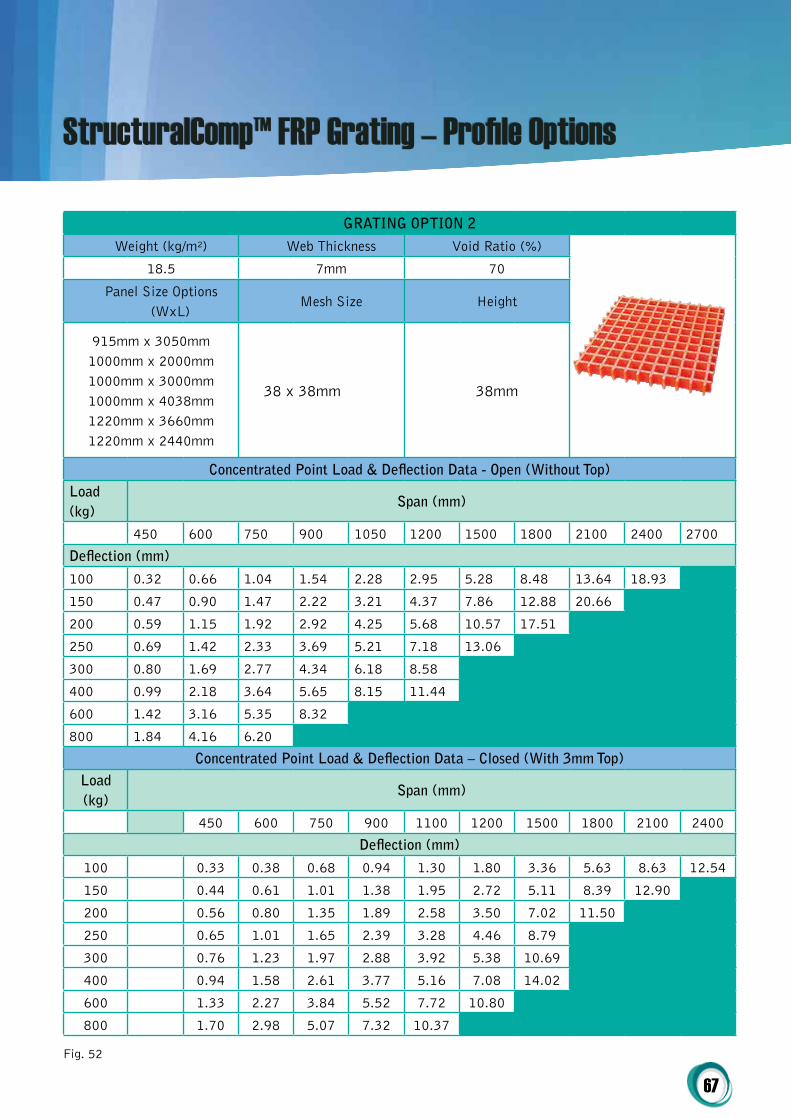
grAtiNg optioN 2
Weight (kg/m²) Web Thickness Void Ratio (%)
18.5 7mm 70
Panel Size Options (WxL)
Mesh Size Height
915mm x 3050mm1000mm x 2000mm1000mm x 3000mm1000mm x 4038mm1220mm x 3660mm1220mm x 2440mm
38 x 38mm 38mm
concentrated point Load & Deflection Data - open (Without top)Load (kg)
Span (mm)
450 600 750 900 1050 1200 1500 1800 2100 2400 2700
Deflection (mm)
100 0.32 0.66 1.04 1.54 2.28 2.95 5.28 8.48 13.64 18.93
150 0.47 0.90 1.47 2.22 3.21 4.37 7.86 12.88 20.66
200 0.59 1.15 1.92 2.92 4.25 5.68 10.57 17.51
250 0.69 1.42 2.33 3.69 5.21 7.18 13.06
300 0.80 1.69 2.77 4.34 6.18 8.58
400 0.99 2.18 3.64 5.65 8.15 11.44
600 1.42 3.16 5.35 8.32
800 1.84 4.16 6.20
concentrated point Load & Deflection Data – closed (With 3mm top)Load (kg)
Span (mm)
450 600 750 900 1100 1200 1500 1800 2100 2400
Deflection (mm)
100 0.33 0.38 0.68 0.94 1.30 1.80 3.36 5.63 8.63 12.54
150 0.44 0.61 1.01 1.38 1.95 2.72 5.11 8.39 12.90
200 0.56 0.80 1.35 1.89 2.58 3.50 7.02 11.50
250 0.65 1.01 1.65 2.39 3.28 4.46 8.79
300 0.76 1.23 1.97 2.88 3.92 5.38 10.69
400 0.94 1.58 2.61 3.77 5.16 7.08 14.02
600 1.33 2.27 3.84 5.52 7.72 10.80
800 1.70 2.98 5.07 7.32 10.37
Fig. 52
StructuralComp™ FRP Grating – Profile Options
68
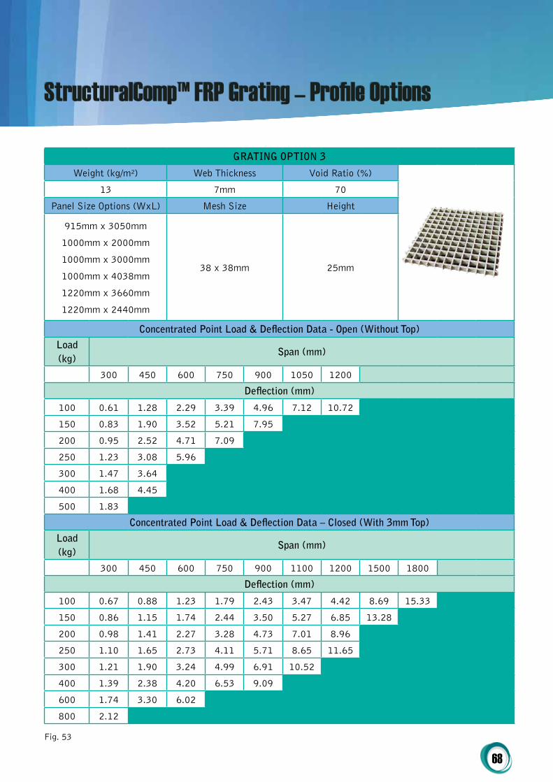
grAtiNg optioN 3
Weight (kg/m²) Web Thickness Void Ratio (%)
13 7mm 70
Panel Size Options (WxL) Mesh Size Height
915mm x 3050mm
1000mm x 2000mm
1000mm x 3000mm
1000mm x 4038mm
1220mm x 3660mm
1220mm x 2440mm
38 x 38mm 25mm
concentrated point Load & Deflection Data - open (Without top)
Load (kg)
Span (mm)
300 450 600 750 900 1050 1200
Deflection (mm)
100 0.61 1.28 2.29 3.39 4.96 7.12 10.72
150 0.83 1.90 3.52 5.21 7.95
200 0.95 2.52 4.71 7.09
250 1.23 3.08 5.96
300 1.47 3.64
400 1.68 4.45
500 1.83
concentrated point Load & Deflection Data – closed (With 3mm top)
Load (kg)
Span (mm)
300 450 600 750 900 1100 1200 1500 1800
Deflection (mm)
100 0.67 0.88 1.23 1.79 2.43 3.47 4.42 8.69 15.33
150 0.86 1.15 1.74 2.44 3.50 5.27 6.85 13.28
200 0.98 1.41 2.27 3.28 4.73 7.01 8.96
250 1.10 1.65 2.73 4.11 5.71 8.65 11.65
300 1.21 1.90 3.24 4.99 6.91 10.52
400 1.39 2.38 4.20 6.53 9.09
600 1.74 3.30 6.02
800 2.12
Fig. 53
StructuralComp™ FRP Grating – Profile Options

69
All Recycled Wood Plastic Composite decking is
provided in project lengths, meaning very little
on-site cutting and therefore wastage. In most
cases, decking is also provided pre-drilled with
oversize countersunk holes to prevent this from
being done on site. The only exception to this is
where a SISCo-FC™ system may have curves and
therefore boards are provided without holes to
allow for accurate on-site drilling.
coreSpan™ Wpc / Frp DEcKiNg & Wpc Decking – colour options
Wpc Decking – coLoUr optioNS
Ash grey copper Desert red Saddle Brown
Fig. 54
coreSpan™ Wpc / Frp MULti coMpoSitE DEcKiNg
Weight Height Width
6.7(kg/m) 40mm 200mm
Fixing Options
Screw Fix (with pre-drilling) YES
Screw Fix (without pre-drilling) NO
Hidden Fixing System YES
Maximum Span Maximum Cantilever Slip Ratings Fire Rating
1200mm 300mm W (TBC) R12 (TBC) BAL (TBC)
Fig. 55
CoreSpan™ WPC / FRP Decking & WPC Decking

70
Wpc DEcKiNg optioN 1
Weight Height Width
4.2 25mm 140mm
Fixing Options
Screw Fix (with pre-drilling) YES
Screw Fix (without pre-drilling) NO
Hidden Fixing System YES
Maximum Span Maximum Cantilever Slip Ratings Fire Rating
450mm 150mm (W (TBC) R12 (TBC) BAL (TBC)
Fig. 56
Wpc DEcKiNg optioN 2
Weight Height Width
5.5 30mm 140mm
Fixing Options
Screw Fix (with pre-drilling) YES
Screw Fix (without pre-drilling) NO
Hidden Fixing System YES
Maximum Span Maximum Cantilever Slip Ratings Fire Rating
550mm 200mm W (TBC) R12 (TBC) BAL (TBC)
Fig. 57
Please contact SIS on either 1300 261 074 or [email protected] to request product samples of any of the above grating or decking options.
71
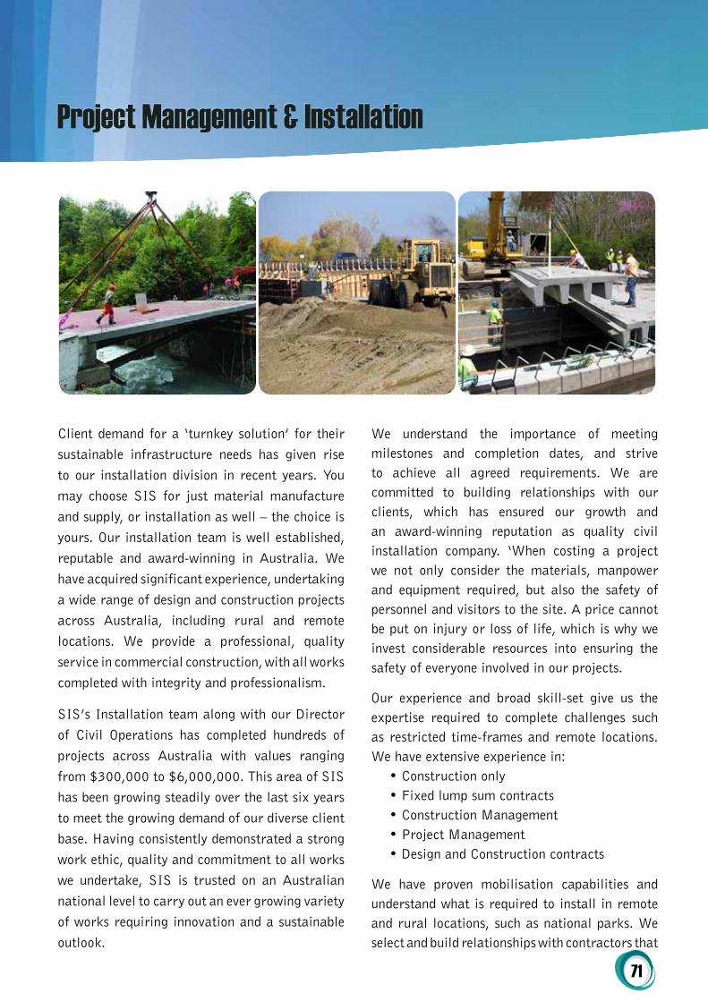
Client demand for a ‘turnkey solution’ for their sustainable infrastructure needs has given rise to our installation division in recent years. You may choose SIS for just material manufacture and supply, or installation as well – the choice is yours. Our installation team is well established, reputable and award-winning in Australia. We have acquired significant experience, undertaking a wide range of design and construction projects across Australia, including rural and remote locations. We provide a professional, quality service in commercial construction, with all works completed with integrity and professionalism.
SIS’s Installation team along with our Director of Civil Operations has completed hundreds of projects across Australia with values ranging from $300,000 to $6,000,000. This area of SIS has been growing steadily over the last six years to meet the growing demand of our diverse client base. Having consistently demonstrated a strong work ethic, quality and commitment to all works we undertake, SIS is trusted on an Australian national level to carry out an ever growing variety of works requiring innovation and a sustainable outlook.
We understand the importance of meeting milestones and completion dates, and strive to achieve all agreed requirements. We are committed to building relationships with our clients, which has ensured our growth and an award-winning reputation as quality civil installation company. ‘When costing a project we not only consider the materials, manpower and equipment required, but also the safety of personnel and visitors to the site. A price cannot be put on injury or loss of life, which is why we invest considerable resources into ensuring the safety of everyone involved in our projects.
Our experience and broad skill-set give us the expertise required to complete challenges such as restricted time-frames and remote locations. We have extensive experience in:
• Construction only• Fixed lump sum contracts• Construction Management• Project Management• Design and Construction contracts
We have proven mobilisation capabilities and understand what is required to install in remote and rural locations, such as national parks. We select and build relationships with contractors that
Project Management & Installation
72
understand the complications involved in working outside of any metropolitan area. We believe the key to building in remote and rural locations is sequential planning. During pre-construction, we conduct scheduling meetings with proven service contractors, including electrical, plumbing, mechanical and fire, to discuss lead times and the methodology to transport materials and construct in a distant location.
Our team has successfully mobilised projects within one to one and half weeks, a rare feat in our industry, and have the proven know-how to deliver large-scale projects Australia wide. Once the installation and any additional civil works has been completed, a formal handover process takes place between the client and our project manager. Unless an ongoing maintenance contract is held with SIS, this is the final stage of the project life-cycle in terms of delivery to the client.
iNStALLAtioN & coNStrUctioN AWArDS
The team at SIS prides itself on surpassing expectations in every way, from design and manufacturing through to installation and hand-over.
Our installation team has been awarded the 2009 Master Builders Association – Building Excellence Award and also the 2012 Master Builders Association – Commercial/ Industrial Building up to $1m.
MANAgEMENt SyStEMS
Sustainable Infrastructures Systems (Aust.) Pty Ltd is environmentally, quality and customer service focused and this, plus exceptional safety standards and environmental diligence, is demonstrated through our Management Systems. We are committed to following the Quality Assurance initiatives stipulated in the standard ISO 9001:2008 and to its continuous improvement.
Our goal is to provide the highest quality service and products to surpass the needs and expectations of our clients and stakeholders. SIS is committed to manufacturing and construction excellence. To achieve this we continually identify, set, measure and review our quality objectives. We have developed and implemented written procedures to ensure our capability for consistently providing a quality service that;
• Exceeds our customer’s needs;• Meets the requirements of applicable
legislation;• Allows us to operate with increased
effectiveness and efficiency with the overall aim of continually improving our business systems.
A Quality Management Plan is produced for every project undertaken by SIS (using template QMP 04.1) to act as an interface between client’s requirements and the SIS Quality Management System. This Quality Management Plan is provided to our client at project commencement and includes;
• Information about the project;• Communication channels between the client
and SIS;• The Quality Assurance responsibilities;• Reference to the Quality System;• Purchasing initiatives;• Commitments to service;• Commitments to care for client’s property;• Initiatives for accuracy;• Control of Non Conformance;• A customised Inspection Test Plan;• Sign off and commitment.
ENViroNMENtAL MANAgEMENt SyStEM
Our Environmental Management Implementation Plan (EMP) has been developed to ensure full and complete compliance with any statutory and regulatory environmental obligations. It is our policy to meet these environmental management requirements and to exceed current industry

73
best practice where possible. All supply and install contracts are managed in accordance with our Environmental Management System together with plans and procedures provided by clients. From an operational perspective, this includes identifying and assessing all potential environmental hazards from onsite at the quotation stage, and again immediately prior to undertaking works using the Risk Assessment of the Daily Job Sheet.
The aim of SIS is to whilst any project installation, minimise our impact on the environment throughout project activities including;
• To ensure that the quality of surface water leaving the site is acceptable during the construction phase;
• To minimise negative impacts on any significant, protected or natural areas of vegetation on or adjacent to the site, and to comply with native vegetation conditions;
• To identify, assess and control risk arising from erosion and sediment generated from operations carried out by SIS;
• To minimise any dust and nuisance noise emissions;
• To be aware of;1. The potential for the contamination of the
site;2. The potential for environmental impact of
wastes generated on site;3. The impacts arising from site activities
on items or areas of cultural heritage significance.
occUpAtioNAL hEALth & SAFEty MANAgEMENt SyStEM
SIS management recognises their absolute responsibility in ensuring the health and safety of every employee, contractor, visitor and ‘other’ person within the business and adopts a risk management strategy in the planning, implementation and management of its operations so as to minimise potential safety
hazards and environmental impact. Employees
are trained and empowered to recognise, identify
and report potential safety hazards and potential
environmental impact.
We are committed to maintaining the highest
possible standards of health, safety and wellbeing
for employees, contractors and visitors across all
operations.
The success of our business is dependent on the
capability, commitment and productivity of our
employees and our sub-contractors. We aim to
operate safely, efficiently and to be the preferred
supply and install company within the sectors in
which we operate.
Sustainable Infrastructure Systems (Aust) Pty Ltd:
• Complies with Occupational Health and
Safety Act and associated statutory
requirements;
• Maintains a safety culture within the
company;
• Is regarded as pro-active and committed to
OHS&W
• Has a target of zero injuries or illness due
to work
SIS has an ongoing commitment to provide safe
systems of work to ensure that, as far as reasonably
practicable, a safe working environment is
maintained and by providing this Management
System, SIS defines the mechanisms to ensure
compliance from management and employees
directly by SIS and also via subcontractors.
The Hazard Management process should be part
of everyday activities on construction sites and
associated activities. To ensure an adequate focus
on potential hazards, some purposeful attention
should be directed towards hazard identification.
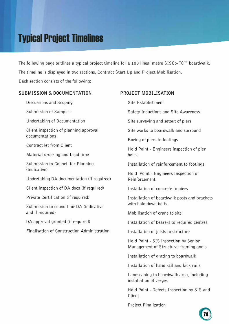
74
SUBMiSSioN & DocUMENtAtioN
Discussions and Scoping
Submission of Samples
Undertaking of Documentation
Client inspection of planning approval documentations
Contract let from Client
Material ordering and Lead time
Submission to Council for Planning (indicative)
Undertaking DA documentation (if required)
Client inspection of DA docs (if required)
Private Certification (if required)
Submission to coundil for DA (indicative and if required)
DA approval granted (if required)
Finalisation of Construction Administration
proJEct MoBiLiSAtioN
Site Establishment
Safety Inductions and Site Awareness
Site surveying and setout of piers
Site works to boardwalk and surround
Boring of piers to footings
Hold Point - Engineers inspection of pier holes
Installation of reinforcement to footings
Hold Point - Engineers Inspection of Reinforcement
Installation of concrete to piers
Installation of boardwalk posts and brackets with hold down bolts
Mobilisation of crane to site
Installation of bearers to required centres
Installation of joists to structure
Hold Point - SIS inspection by Senior Management of Structural framing and s
Installation of grating to boardwalk
Installation of hand rail and kick rails
Landscaping to boardwalk area, including installation of verges
Hold Point - Defects Inspection by SIS and Client
Project Finalization
Typical Project Timelines
The following page outlines a typical project timeline for a 100 lineal metre SISCo-FC™ boardwalk.
The timeline is displayed in two sections, Contract Start Up and Project Mobilisation.
Each section consists of the following:

75
25 Mar’13 1 Apr’13 8 Apr’13 15 Apr’13 22 Apr’13 29 Apr’13 6 May’13 13 May’13 20 May’13 27 May’13 3 Jun’13 10 Jun’13 17 Jun’13 24 Jun’13 1 Jul’13 8 Jul’13 15 Jul’13 22 Jul’13 M T W T F S S M T W T F S S M T W T F S S M T W T F S S M T W T F S S M T W T F S S M T W T F S S M T W T F S S M T W T F S S M T W T F S S M T W T F S S M T W T F S S M T W T F S S M T W T F S S M T W T F S S M T W T F S S M T W T F S S M T W T F S S
Task Project Summary External Tasks External Milestone Deadline
Dec’12 7 Jan’13 14 Jan’13 21 Jan’13 28 Jan’13 4 Feb’13 11 Feb’13 18 Feb’13 25 Feb’13 4 Mar’13 11 Mar’13 18 Mar’13 25 Mar’13 1 Apr’13 8 Apr’13 15 Apr’13 M T W T F S S M T W T F S S M T W T F S S M T W T F S S M T W T F S S M T W T F S S M T W T F S S M T W T F S S M T W T F S S M T W T F S S M T W T F S S M T W T F S S M T W T F S S M T W T F S S M T W T F S S M T W T F S S
Task Name
SIS – Boardwalk Construction 100m long x 2m wide x 1m of the ground surface
Project Mobilisation
Site Establishment
Safety Inductions and Site Awareness
Site surveying and setout of piers
Site works to boardwalk and surround
Boring of piers to footings
Hold Point – Engineers inspection of pier holes
Installation of reinforcement to footings
Hold Point - Engineers inspection of Reinforcement
Installation of concrete to piers
Installation of boardwalk posts and brackets with hold down bolts
Mobilisation of crane to site
Installation of bearers to required centres
Installation of joists to structure
Hold Point – SIS inspection by Senior Management of Structural framing and signo�
Installation of grating to boardwalk
Installation of hand rail and kick rails
Landscaping to boardwalk area, including installation of verges
Hold Point – Defects Inspection by SIS and Client
Project Finalization
ID
1
2
3
4
5
6
7
8
9
10
11
12
13
14
15
16
17
18
19
20
21
Duration
62 days
62 days
3 days
2 days
4 days
5 days
5 days
0 days
4 days
0 days
5 days
6 days
2 days
5 days
8 days
0 days
6 days
5 days
4 days
0 days
0 days
Start
Mon 1/04/13
Mon 1/04/13
Mon 1/04/13
Thu 4/04/13
Mon 8/04/13
Fri 12/04/13
Fri 19/04/13
Thu 25/04/13
Fri 26/04/13
Wed 1/05/13
Thu 2/05/13
Thu 9/05/13
Thu 16/05/13
Mon 20/05/13
Fri 24/05/13
Tue 4/06/13
Wed 5/06/13
Thu 13/06/13
Thu 20/06/13
Tue 25/06/13
Tue 25/06/13
Finish
Tue 25/06/13
Tue 25/06/13
Wed 3/04/13
Fri 5/04/13
Thu 11/04/13
Thu 18/04/13
Thu 25/04/13
Thu 25/04/13
Wed 1/05/13
Wed 1/05/13
Wed 8/05/13
Thu 16/05/13
Fri 17/05/13
Fri 24/05/13
Tue 4/06/13
Tue 4/06/13
Wed 12/06/13
Wed 19/06/13
Tue 25/06/13
Tue 25/06/13
Tue 25/06/13
Site Establishment
Safety Inductions and Site Awareness
Site surveying and setout of piers
Site works to boardwalk and surround
Boring of piers to footings
25/04
Installation of reinforcement to footings
Installation of concrete to piers
Installation of boardwalk posts and brackets with hold down bolts
Mobilisation of crane to site
Installation of bearers to required centres
Installation of joists to structure
Installation of grating to boardwalk
Installation of hand rail and kick rails
Landscaping to boardwalk area, including installation of verges
25/06
25/06
4/06
1/05
SIS – Indicative Program – 100m Boardwalk and 1m from GL at 2m in width – Construction
Project: SIS Indicative Program - ConstrDate: 1st Jan 2013
Split . . . . . . Progress Milestone Summary
Task Project Summary External Tasks External Milestone DeadlineProject: SIS Indicative Program - ConstrDate: 1st Jan 2013
Split . . . . . . Progress Milestone Summary
Task Name
SIS – Boardwalk Construction 100m long x 2m wide x 1m of the ground surface
Contract Start up
Discussions and scoping
Submission of Samples
Undertaking of documentation
Client inspection of planning approval documentation
Contract let from the Client
Material ordering and lead time
Submission to council for planning (indicative)
Undertaking DA documentation (if required)
Client inspection of DA docs (if required)
Private Certi�cation (if required)
Submission to council for DA (indicative and if required)
DA approval granted (if required)
Finalisation of Construction administration
ID
1
2
3
4
5
6
7
8
9
10
11
12
13
14
15
Duration
59 days
59 days
3 days
2 days
8 days
3 days
2 days
40 days
12 days
18 days
6 days
6 days
7 days
3 days
0 days
Start
Thu 3/01/13
Thu 3/01/13
Thu 3/01/13
Tue 8/01/13
Thu 10/01/13
Tue 22/01/13
Wed 23/01/13
Mon 21/01/13
Wed 23/01/13
Wed 30/01/13
Mon 25/02/13
Tue 5/03/13
Wed 13/03/13
Fri 22/03/13
Tue 26/03/13
Finish
Tue 25/06/13
Tue 25/06/13
Wed 3/04/13
Fri 5/04/13
Thu 11/04/13
Thu 18/04/13
Thu 25/04/13
Thu 25/04/13
Wed 1/05/13
Wed 1/05/13
Wed 8/05/13
Thu 16/05/13
Fri 17/05/13
Fri 24/05/13
Tue 4/06/13
Undertaking of documentation
Client inspection of planning approval documentation
Contract let from the Client
Material ordering and lead time
Submission to council for planning (indicative)
Undertaking DA documentation (if required)
Client inspection of DA docs (if required)
Submission to council for DA (indicative and if required)
DA approval granted (if required)
26/03
Private Certi�cation (if required)
SIS – Indicative Program – 100m Boardwalk and 1m from GL at 2m in width – Administration
Discussions and scoping
Submission of Samples
Fig. 58. Copyright 2014 Sustainable Infrastructure Systems (Aust) Pty Ltd.58

76
Listed below is INDICATIVE PRICING only. Please contact SIS for quantity / project pricing. Pricing is ex Adelaide. For larger projects or stocking orders freight can be quoted to any Australian capital city. All pricing is quoted in $AUD
NOTE: For pricing on EXTREN DWB® hybrid and all-glass members contact SIS.
Pricing
iNDicAtiVE priciNg
CODE COMPONENT PRICE ex GST
SIS-FCS-250JB-0000250 Joist / Bearer - StructuralComp™ I Beam 250mm x 125mm x 12mm
$127.50/m
SIS-FCS-609JB-0000609 Joist / Bearer - StructuralComp™ I Beam 609mm x 9.5mm x 190mm x 19.1mm
$236.20/m
SIS-FCS-PILE-0000 Piles - StructuralComp™ SHS 120mm x 120mm x 8mm $62.45/m
SIS-FCS-BRACE-0000 Brace - StructuralComp™ Plate 75mm x 10mm $4.85/m
SIS-FCS-HRHS-0000Handrail Horizontal Support - StructuralComp™ SHS 101.6mm x 6.35mm
$49.18/m
SIS-FCS-HRS-0000Handrail Stanchion - StructuralComp™ SHS 101.6mm x 6.35mm
$49.18/m
SIS-FCS-HR-0000 Handrail - StructuralComp™ CHS 50.8mm x 6.4mm $7.43/m
SIS-FCS-BKT-1Pile to Bearer / Footing Bracket - StructuralComp™ 125mm x 172mm x 280mm x 12mm
$22.09ea
SIS-FCS-BKT-2Joist to Bearer Bracket - StructuralComp™ 530mm x 172mm x 165mm x 12mm
$56.12ea
SIS-FCS-BKT-3Handrail Horizontal Support to Handrail Stanchion Bracket - StructuralComp™ 175mm x 250mm x 10mm
$8.22ea
SIS-FCS-BKT-4Handrail to Handrail Stanchion Bracket - StructuralComp™ 16mm x 100mm x 166mm
$7.60ea
SIS-FCS-CPNT-1Capping (Handrail Horizontal Support) - Recycled Plastic Insert Cap (Flush)
$1.88ea
SIS-FCS-CPNT-2In Plain Joist to Bearer Packer - StructuralComp™ 165mm x 530mm x 10mm
$7.10ea
SIS-FCS-CPNT-3Pile to Bearer Packer - StructuralComp™ 280mm x 125mm x 5mm
$5.90ea
SIS-FCS-CPNT-4Handrail Internal Connection Sleeve - StructuralComp™ 38.1mm x 6.4mm CHS (160mm)
$1.03ea
SIS-FCS-CPNT-5Anti-Crush Tubes - StructuralComp™ 21.8mm x 2.4mm x 119mm CHS
$1.22ea
SIS-FCS-CPNT-6 Handrail Adhesive - SCOTCHWELD DP8010 TBA

77
iNDicAtiVE priciNg
CODE COMPONENT PRICE ex GST
SIS-FCS-CPNT-7 FRP Sealent TBA
SIS-FCS-CPNT-8 Non Shrink Grout TBA
SIS-FCS-CPNT-9Superstructure Bolted Connection Fixings - G10/FR4 19mm Bolts / Washers / Nuts
$8.15ea
SIS-FCS-CPNT-10Pile to Footing Bracket Fixings (to Footing) - M16 Chem Anchors
TBA
SIS-FCS-CPNT-11Kickrail to Deck Fixings - G10/FR4 M12 Countersunk Bolt / Nut / Washer (Hex Head)
$3.18ea
SIS-FCS-CPNT-12Handrail Internal Sleeve Fixing - G10/FR4 M8 Countersunk Screws
$2.33ea
SIS-FCS-CPNT-13Handrail to Handrail Stanchion Bracket Fixing - G10/FR4 M8 Screws
$2.33ea
SIS-FCS-COC-1Large Span Decking - CoreSpan™ FRP/WPC 200mm x 40mm Large Span Decking
$25.70/m
SIS-FCS-COC-2 WPC Decking Option 1 - Recycled WPC 140mm x 25mm $12.01/m
SIS-FCS-COC-3 WPC Decking Option 2 - Recycled WPC 140mm x 30mm $15.90/m
SIS-FCS-COC-4FRP Grating Option 1 - StructuralComp™ FRP 50mm x 50mm x 50mm Grating
$89.90sq/m
SIS-FCS-COC-5FRP Grating Option 1 With Top - StructuralComp™ FRP 50mm x 50mm x 50mm Grating with 3mm Top
$101.12sq/m
SIS-FCS-COC-6FRP Grating Option 2 - StructuralComp™ FRP 38mm x 38mm x 38mm Grating
$72.30sq/m
SIS-FCS-COC-7FRP Grating Option 2 With Top - StructuralComp™ FRP 38mm x 38mm x 38mm Grating with 3mm Top
$78.60sq/m
SIS-FCS-COC-8FRP Grating Option 3 - StructuralComp™ FRP 38mm x 38mm x 25mm Grating
$61.80sq/m
SIS-FCS-COC-9FRP Grating Option 3 With Top - StructuralComp™ FRP 38mm x 38mm x 25mm Grating with 3mm Top
$68.22sq/m
SIS-FCS-COC-10 Handrail Infill Option 1 - Stainless Steel Wire TBA
SIS-FCS-COC-11 Handrail Infill Option 2 - Vertical Aluminium Panel TBA
SIS-FCS-COC-12 Handrail Infill Option 3 - Vertical Recycled WPC Panel TBA
SIS-FCS-COC-13 Kick Rail - Recycled WPC 90mm x 45mm $9.89/m
SIS-FCS-COC-14 Kick Rail Blocks - Recycled WPC 90mm x 45mmx 100mm $1.22ea
Fig. 59
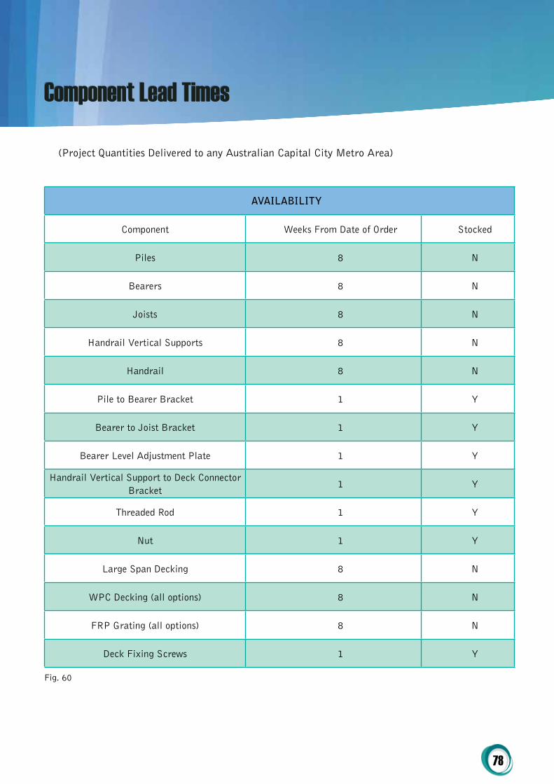
78
(Project Quantities Delivered to any Australian Capital City Metro Area)
AVAiLABiLity
Component Weeks From Date of Order Stocked
Piles 8 N
Bearers 8 N
Joists 8 N
Handrail Vertical Supports 8 N
Handrail 8 N
Pile to Bearer Bracket 1 Y
Bearer to Joist Bracket 1 Y
Bearer Level Adjustment Plate 1 Y
Handrail Vertical Support to Deck Connector Bracket
1 Y
Threaded Rod 1 Y
Nut 1 Y
Large Span Decking 8 N
WPC Decking (all options) 8 N
FRP Grating (all options) 8 N
Deck Fixing Screws 1 Y
Fig. 60
Component Lead Times

79
coDEDrAWiNg MArK /
rEFErENcEMEMBErS pArticULArS
SIS-FCS-250JB-0000 B2 250 Joist / Bearer StructuralComp™ I Beam 250mm x 125mm x 12mm
SIS-FCS-609JB-0000 B2 609 Joist / BearerStructuralComp™ I Beam 609mm x 9.5mm x 190mm x 19.1mm
SIS-FCS-PILE-0000 C1 Piles StructuralComp™ SHS 120mm x 120mm x 8mm
SIS-FCS-BRACE-0000 LBR1, LBR2 Brace StructuralComp™ Plate 75mm x 10mm
SIS-FCS-HRHS-0000 B3 Handrail Horizontal Support StructuralComp™ SHS 101.6mm x 6.35mm
SIS-FCS-HRS-0000 Stanchion Handrail Stanchion StructuralComp™ SHS 101.6mm x 6.35mm
SIS-FCS-HR-0000 Handrail Handrail StructuralComp™ CHS 50.8mm x 6.4mm
coDEDrAWiNg MArK /
rEFErENcEBrAcKEtS pArticULArS
SIS-FCS-BKT-1 Pile to Bearer / Footing Bracket Pile to Bearer / Footing Bracket StructuralComp™ 125mm x 172mm x 280mm x 12mm
SIS-FCS-BKT-2 Joist to Bearer Bracket Joist to Bearer Bracket StructuralComp™ 530mm x 172mm x 165mm x 12mm
SIS-FCS-BKT-3 10LPLHandrail Horizontal Support to Handrail Stanchion Bracket
StructuralComp™ 175mm x 250mm x 10mm
SIS-FCS-BKT-4 16x100 Long Bent PLHandrail to Handrail Stanchion Bracket
StructuralComp™ 16mm x 100mm x 166mm
coDEDrAWiNg MArK /
rEFErENcEcoMpoNENtS & FiXiNgS pArticULArS
SIS-FCS-CPNT-1 CappingCapping (Handrail Horizontal Support)
Recycled Plastic Insert Cap (Flush)
SIS-FCS-CPNT-2 10 Max Packer In Plain Joist to Bearer Packer StructuralComp™ 165mm x 530mm x 10mm
SIS-FCS-CPNT-3 Packer Pile to Bearer Packer StructuralComp™ 280mm x 125mm x 5mm
How to Specify
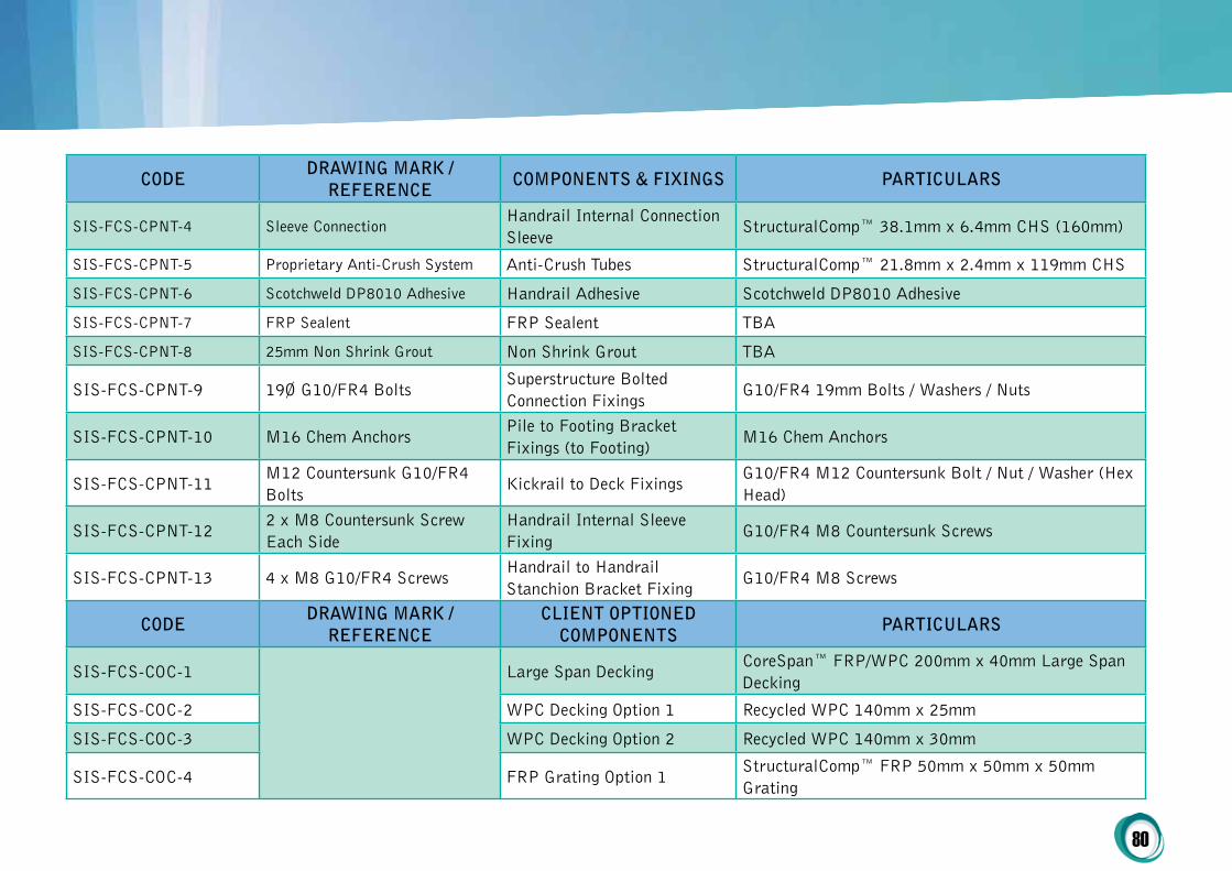
80
coDEDrAWiNg MArK /
rEFErENcEcoMpoNENtS & FiXiNgS pArticULArS
SIS-FCS-CPNT-4 Sleeve ConnectionHandrail Internal Connection Sleeve
StructuralComp™ 38.1mm x 6.4mm CHS (160mm)
SIS-FCS-CPNT-5 Proprietary Anti-Crush System Anti-Crush Tubes StructuralComp™ 21.8mm x 2.4mm x 119mm CHS
SIS-FCS-CPNT-6 Scotchweld DP8010 Adhesive Handrail Adhesive Scotchweld DP8010 Adhesive
SIS-FCS-CPNT-7 FRP Sealent FRP Sealent TBA
SIS-FCS-CPNT-8 25mm Non Shrink Grout Non Shrink Grout TBA
SIS-FCS-CPNT-9 19Ø G10/FR4 BoltsSuperstructure Bolted Connection Fixings
G10/FR4 19mm Bolts / Washers / Nuts
SIS-FCS-CPNT-10 M16 Chem AnchorsPile to Footing Bracket Fixings (to Footing)
M16 Chem Anchors
SIS-FCS-CPNT-11M12 Countersunk G10/FR4 Bolts
Kickrail to Deck FixingsG10/FR4 M12 Countersunk Bolt / Nut / Washer (Hex Head)
SIS-FCS-CPNT-122 x M8 Countersunk Screw Each Side
Handrail Internal Sleeve Fixing
G10/FR4 M8 Countersunk Screws
SIS-FCS-CPNT-13 4 x M8 G10/FR4 ScrewsHandrail to Handrail Stanchion Bracket Fixing
G10/FR4 M8 Screws
coDEDrAWiNg MArK /
rEFErENcEcLiENt optioNED
coMpoNENtSpArticULArS
SIS-FCS-COC-1 Large Span DeckingCoreSpan™ FRP/WPC 200mm x 40mm Large Span Decking
SIS-FCS-COC-2 WPC Decking Option 1 Recycled WPC 140mm x 25mm
SIS-FCS-COC-3 WPC Decking Option 2 Recycled WPC 140mm x 30mm
SIS-FCS-COC-4 FRP Grating Option 1StructuralComp™ FRP 50mm x 50mm x 50mm Grating

81
coDEDrAWiNg MArK /
rEFErENcEcLiENt optioNED
coMpoNENtSpArticULArS
SIS-FCS-COC-5FRP Grating Option 1 With Top
StructuralComp™ FRP 50mm x 50mm x 50mm Grating with 3mm Top
SIS-FCS-COC-6 FRP Grating Option 2StructuralComp™ FRP 38mm x 38mm x 38mm Grating
SIS-FCS-COC-7FRP Grating Option 2 With Top
StructuralComp™ FRP 38mm x 38mm x 38mm Grating with 3mm Top
SIS-FCS-COC-8 FRP Grating Option 3StructuralComp™ FRP 38mm x 38mm x 25mm Grating
SIS-FCS-COC-9FRP Grating Option 3 With Top
StructuralComp™ FRP 38mm x 38mm x 25mm Grating with 3mm Top
SIS-FCS-COC-10 Handrail Infill Option 1 Stainless Steel Wire
SIS-FCS-COC-11 Handrail Infill Option 2 Vertical Aluminium Panel
SIS-FCS-COC-12 Handrail Infill Option 3 Vertical Recycled WPC Panel
SIS-FCS-COC-13 Kick Rail Recycled WPC 90mm x 45mm
SIS-FCS-COC-14 Kick Rail Blocks Recycled WPC 90mm x 45mmx 100mm
Fig. 61
*NOTE: Bolt set includes bolt, nut and 2 x washers*NOTE: SIS-FCS-BSA is used at Pile to Bearer Bracket (to bearer only) and Joist to Bearer (All)*NOTE: Items not specified on this table are due to design options – i.e. handrail components
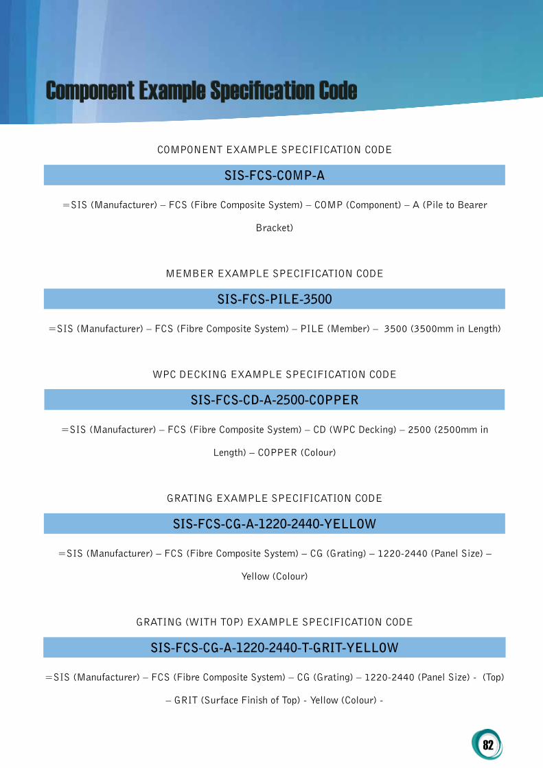
82
COMPONENT EXAMPLE SPECIFICATION CODE
SiS-FcS-coMp-A
=SIS (Manufacturer) – FCS (Fibre Composite System) – COMP (Component) – A (Pile to Bearer
Bracket)
MEMBER EXAMPLE SPECIFICATION CODE
SiS-FcS-piLE-3500
=SIS (Manufacturer) – FCS (Fibre Composite System) – PILE (Member) – 3500 (3500mm in Length)
WPC DECKING EXAMPLE SPECIFICATION CODE
SiS-FcS-cD-A-2500-coppEr
=SIS (Manufacturer) – FCS (Fibre Composite System) – CD (WPC Decking) – 2500 (2500mm in
Length) – COPPER (Colour)
GRATING EXAMPLE SPECIFICATION CODE
SiS-FcS-cg-A-1220-2440-yELLoW
=SIS (Manufacturer) – FCS (Fibre Composite System) – CG (Grating) – 1220-2440 (Panel Size) –
Yellow (Colour)
GRATING (WITH TOP) EXAMPLE SPECIFICATION CODE
SiS-FcS-cg-A-1220-2440-t-grit-yELLoW
=SIS (Manufacturer) – FCS (Fibre Composite System) – CG (Grating) – 1220-2440 (Panel Size) - (Top)
– GRIT (Surface Finish of Top) - Yellow (Colour) -
Component Example Specification Code
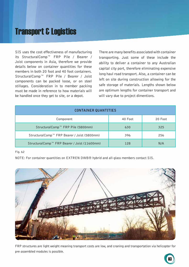
83
SIS uses the cost effectiveness of manufacturing its StructuralComp™ FRP Pile / Bearer / Joist components in Asia, therefore we provide details below on container quantities for these members in both 20 foot and 40 foot containers. StructuralComp™ FRP Pile / Bearer / Joist components can be packed loose, or on steel stillages. Consideration in to member packing must be made in reference to how materials will be handled once they get to site, or a depot.
There are many benefits associated with container transporting. Just some of these include the ability to deliver a container to any Australian capital city port, therefore eliminating expensive long haul road transport. Also, a container can be left on site during construction allowing for the safe storage of materials. Lengths shown below are optimum lengths for container transport and will vary due to project dimentions.
Transport & Logistics
coNtAiNEr QUANtitiES
Component 40 Foot 20 Foot
StructuralComp™ FRP Pile (5800mm) 630 325
StructuralComp™ FRP Bearer / Joist (5800mm) 396 256
StructuralComp™ FRP Bearer / Joist (11600mm) 128 N/A
Fig. 62
NOTE: For container quantities on EXTREN DWB® hybrid and all-glass members contact SIS.
FRP structures are light weight meaning transport costs are low, and craning and transportation via helicopter for
pre-assembled modules is possible.

84
Other Products From Sustainable Infrastructure Systems
picture SiS product code Wpc hollow rectangular profiles
SIS-WPC-51H30-1000Extruded Hollow Rectangular Profile, 51mm x 30mm
SIS-WPC-85H50-1000Extruded Hollow Rectangular Profile, 85mm x 50mm
SIS-WPC-89H25-1000Extruded Hollow Rectangular Profile, 89mm x 25mm
SIS-WPC-100H30-1000Extruded Hollow Rectangular Profile, 100mm x 30mm
SIS-WPC-100H50-1000Extruded Hollow Rectangular Profile, 100mm x 50mm
SIS-WPC-145H22-1000Extruded Hollow Rectangular Profile, 145mm x 22mm
SIS-WPC-180H80-1000Extruded Hollow Rectangular Profile, 180mm x 80mm
SIS-WPC-160H60-1000Extruded Hollow Rectangular Profile, 160mm x 60mm
SIS-WPC-200H60-1000Extruded Hollow Rectangular Profile, 200mm x 60mm
picture SiS product code Wpc Solid rectangular Sections
SIS-WPC-70S16-1000Extruded Solid Rectangular Profile, 70mm x 16mm
SIS-WPC-140S10-1000Extruded Solid Rectangular Profile, 140mm x 10mm
SIS-WPC-140S20-1000Extruded Solid Rectangular Profile, 140mm x 20mm
SIS-WPC-140S30-1000Extruded Solid Rectangular Profile, 140mm x 30mm
SIS-WPC-147S16-1000Extruded Solid Rectangular Profile, 147mm x 16mm
SIS-WPC-250S20-1000Extruded Solid Rectangular Profile, 250mm x 20mm
SIS-WPC-298S16-1000Extruded Solid Rectangular Profile, 298mm x 16mm
Fig. 63
Fig. 64

85
picture SiS product code Wpc hollow Square Sections
SIS-WPC-51H51-1000Extruded Hollow Square Profile, 51mm x 51mm
SIS-WPC-60H60-1000Extruded Hollow Square Profile, 60mm x 60mm
SIS-WPC-70H70-1000Extruded Hollow Square Profile, 70mm x 70mm
SIS-WPC-90H90-1000Extruded Hollow Square Profile, 90mm x 900mm
SIS-WPC-100H100-1000Extruded Hollow Square Profile, 100mm x 100mm
SIS-WPC-120H120-1000Extruded Hollow Square Profile, 120mm x 120mm
SIS-WPC-150H150-1000Extruded Hollow Square Profile, 150mm x 150mm
SIS-WPC-200H200-1000Extruded Hollow Square Profile, 200mm x 200mm
Fig. 65
picture SiS product code Wpc Solid Decking
SIS-WPC-140S25-1000Extruded Solid Decking Profile, 140mm x 25mm
SIS-WPC-140S30-1000Extruded Solid Decking Profile, 140mm x 30mm
Fig. 66
picture SiS product code Wpc hollow Decking
SIS-WPC-100H25 -1000Extruded Hollow Decking Profile, 100mm x 25mm
Fig. 67
picture SiS product code Wpc Accessories
SIS-WPC-AC-AC01Plastic Hidden System Fixing Clip for WPC Decking
SIS-WPC-AC-AC03Stainless Steel Start Clip for WPC Decking
Fig. 68

86
picture SiS product code coreSpan™ co-Extruded Wpc / Frp
SIS-CEWPC-100x50-1000
CoreSpan™ Co-Extruded Profile, 100mm x 50mm (WPC / FRP Section 50x25x3)
SIS-CEWPC-140x40-1000
CoreSpan™ Co-Extruded Profile, 140mm x 40mm (WPC / FRP Section 100x20x3)
SIS-CEWPC-120x120- 1000
CoreSpan™ Co-Extruded Profile, 120mm x 120mm (WPC / FRP Section 90x90x3)
SIS-CEWPC-140x90-1000
CoreSpan™ Co-Extruded Profile, 140mm x 90mm (WPC / FRP Section 100x50x3)
SIS-CEWPC-70R-1000
CoreSpan™ Co-Extruded Profile, 70mm Round (WPC / FRP Section 42x3)
SIS-CEWPC-90R-1000
CoreSpan™ Co-Extruded Profile, 90mm Round (WPC / FRP Section 59x3)
SIS-CEWPC-120R-1000
CoreSpan™ Co-Extruded Profile, 120mm Round (WPC / FRP Section 48x3)
SIS-CEWPC-150R-1000
CoreSpan™ Co-Extruded Profile, 150mm Round (WPC / FRP Section 88x3)
Fig. 69
picture SiS product code Structuralcomp™ Frp hollow round tubes
SIS-FRP-RH-A1Pultruded Hollow Round Profile, 19mm OD, 14mm ID
SIS-FRP-RH-A2Pultruded Hollow Round Profile, 25.4mm OD, 20.5mm ID
SIS-FRP-RH-A3Pultruded Hollow Round Profile, 25.4mm OD, 18.4mm ID
SIS-FRP-RH-A4Pultruded Hollow Round Profile, 28mm OD, 24mm ID
SIS-FRP-RH-A5Pultruded Hollow Round Profile, 31mm OD, 25mm ID
SIS-FRP-RH-A6Pultruded Hollow Round Profile, 32mm OD, 27.5mm ID
SIS-FRP-RH-A7Pultruded Hollow Round Profile, 32mm OD, 26mm ID
SIS-FRP-RH-A8Pultruded Hollow Round Profile, 33.7mm OD, 27.7mm ID
SIS-FRP-RH-A9Pultruded Hollow Round Profile, 39mm OD, 34mm ID
SIS-FRP-RH-A10Pultruded Hollow Round Profile, 45mm OD, 35mm ID
Fig. 70

87
picture SiS product code Structuralcomp™ Frp Square hollow Sections
SIS-FRP-SH-B1Pultruded Hollow Square Profile, 25.4mm x 25.4mm, 2mm Wall Thickness
SIS-FRP-SH-B2Pultruded Hollow Square Profile, 25.4mm x 25.4mm, 3.2mm Wall Thickness
SIS-FRP-SH-B3Pultruded Hollow Square Profile, 38mm x 38mm, 4mm Wall Thickness
SIS-FRP-SH-B4Pultruded Hollow Square Profile, 41.4mm x 41.4mm, 4.2mm Wall Thickness
SIS-FRP-SH-B5Pultruded Hollow Square Profile, 50mm x 50mm, 4mm Wall Thickness
SIS-FRP-SH-B6Pultruded Hollow Square Profile, 50mm x 50mm, 5mm Wall Thickness
SIS-FRP-SH-B7Pultruded Hollow Square Profile, 50mm x 50mm, 6mm Wall Thickness
SIS-FRP-SH-B8Pultruded Hollow Square Profile, 50.8mm x 50.8mm, 6.35mm Wall Thickness
SIS-FRP-SH-B9Pultruded Hollow Square Profile, 75mm x 75mm, 6mm Wall Thickness
SIS-FRP-SH-B10Pultruded Hollow Square Profile, 76.2mm x 76.2mm, 6.35mm Wall Thickness
SIS-FRP-SH-B11Pultruded Hollow Square Profile, 80mm x 80mm, 6mm Wall Thickness
SIS-FRP-SH-B12Pultruded Hollow Square Profile, 100mm x 100mm, 8mm Wall Thickness
SIS-FRP-SH-B13Pultruded Hollow Square Profile, 120mm x 120mm, 8mm Wall Thickness
SIS-FRP-SH-B14Pultruded Hollow Square Profile, 150mm x 150mm, 8mm Wall Thickness
SIS-FRP-RH-A11Pultruded Hollow Round Profile, 50mm OD, 42mm ID
SIS-FRP-RH-A12Pultruded Hollow Round Profile, 75mm OD, 67mm ID
SIS-FRP-RH-A13Pultruded Hollow Round Profile, 110mm OD, 90mm ID
Fig. 71
Fig. 72

88
picture SiS product code Structuralcomp™ Frp c channel Sections
SIS-FRP-CC-C1Pultruded C-Channel Profile, 50mm x 30mm, 5mm & 5mm Wall Thickness
SIS-FRP-CC-C2Pultruded C-Channel Profile, 52mm x 30mm, 5mm & 5mm Wall Thickness
SIS-FRP-CC-C3Pultruded C-Channel Profile, 57mm x 60mm, 3mm & 3mm Wall Thickness
SIS-FRP-CC-C4Pultruded C-Channel Profile, 60mm x 50mm, 5mm & 5mm Wall Thickness
SIS-FRP-CC-C5Pultruded C-Channel Profile, 70mm x 26mm, 4mm & 3mm Wall Thickness
SIS-FRP-CC-C6Pultruded C-Channel Profile, 79mm x 28.5mm, 3mm & 3mm Wall Thickness
SIS-FRP-CC-C7Pultruded C-Channel Profile, 84mm x 30mm, 5.5mm & 5.5mm Wall Thickness
SIS-FRP-CC-C8Pultruded C-Channel Profile, 100mm x 35mm, 5mm & 5mm Wall Thickness
SIS-FRP-CC-C9Pultruded C-Channel Profile, 100mm x 50mm, 6mm & 6mm Wall Thickness
SIS-FRP-CC-C10Pultruded C-Channel Profile, 101.6mm x 35mm, 4.8mm & 4.8mm Wall Thickness
SIS-FRP-CC-C11Pultruded C-Channel Profile, 150mm x 50mm, 6mm & 6mm Wall Thickness
SIS-FRP-CC-C12Pultruded C-Channel Profile, 150mm x 40mm, 10mm & 10mm Wall Thickness
SIS-FRP-CC-C13Pultruded C-Channel Profile, 152.4mm x 42mm, 6.35mm & 6.35mm Wall Thickness
SIS-FRP-CC-C14Pultruded C-Channel Profile, 152.4mm x 42mm, 9.5mm & 9.5mm Wall Thickness
SIS-FRP-CC-C15Pultruded C-Channel Profile, 200mm x 50mm, 10mm & 10mm Wall Thickness
SIS-FRP-CC-C16Pultruded C-Channel Profile, 203.2mm x 56mm, 9.5mm & 9.5mm Wall Thickness
SIS-FRP-CC-C17Pultruded C-Channel Profile, 250mm x 70mm, 12mm & 12mm Wall Thickness
Fig. 73

89
picture SiS product code Structuralcomp™ Frp Solid round Sections
SIS-FRP-RS-D1 Pultruded Solid Round Profile, 6mm Diameter
SIS-FRP-RS-D2Pultruded Solid Round Profile, 7.9mm Diameter
SIS-FRP-RS-D3Pultruded Solid Round Profile, 10mm Diameter
SIS-FRP-RS-D4Pultruded Solid Round Profile, 12.7mm Diameter
SIS-FRP-RS-D5Pultruded Solid Round Profile, 14mm Diameter
SIS-FRP-RS-D6Pultruded Solid Round Profile, 18mm Diameter
SIS-FRP-RS-D7Pultruded Solid Round Profile, 19mm Diameter
SIS-FRP-RS-D8Pultruded Solid Round Profile, 22mm Diameter
SIS-FRP-RS-D9Pultruded Solid Round Profile, 23.7mm Diameter
SIS-FRP-RS-D10Pultruded Solid Round Profile, 25mm Diameter
SIS-FRP-RS-D11Pultruded Solid Round Profile, 28mm Diameter
SIS-FRP-RS-D12Pultruded Solid Round Profile, 30mm Diameter
SIS-FRP-RS-D13Pultruded Solid Round Profile, 32mm Diameter
Fig. 74
picture SiS product code Structuralcomp™ Frp right Angle Sections
SIS-FRP-RA-E1Pultruded Right Angle Profile, 40mm x 40mm, 4mm & 4mm Wall Thickness
SIS-FRP-RA-E2Pultruded Right Angle Profile, 50mm x 50mm, 5mm & 5mm Wall Thickness
SIS-FRP-RA-E3Pultruded Right Angle Profile, 75mm x 75mm, 6mm & 6mm Wall Thickness
SIS-FRP-RA-E4Pultruded Right Angle Profile, 76.2mm x 76.2mm, 6.4mm & 6.4mm Wall Thickness
SIS-FRP-RA-E5Pultruded Right Angle Profile, 76.2mm x 76.2mm, 8mm & 8mm Wall Thickness
Fig. 75
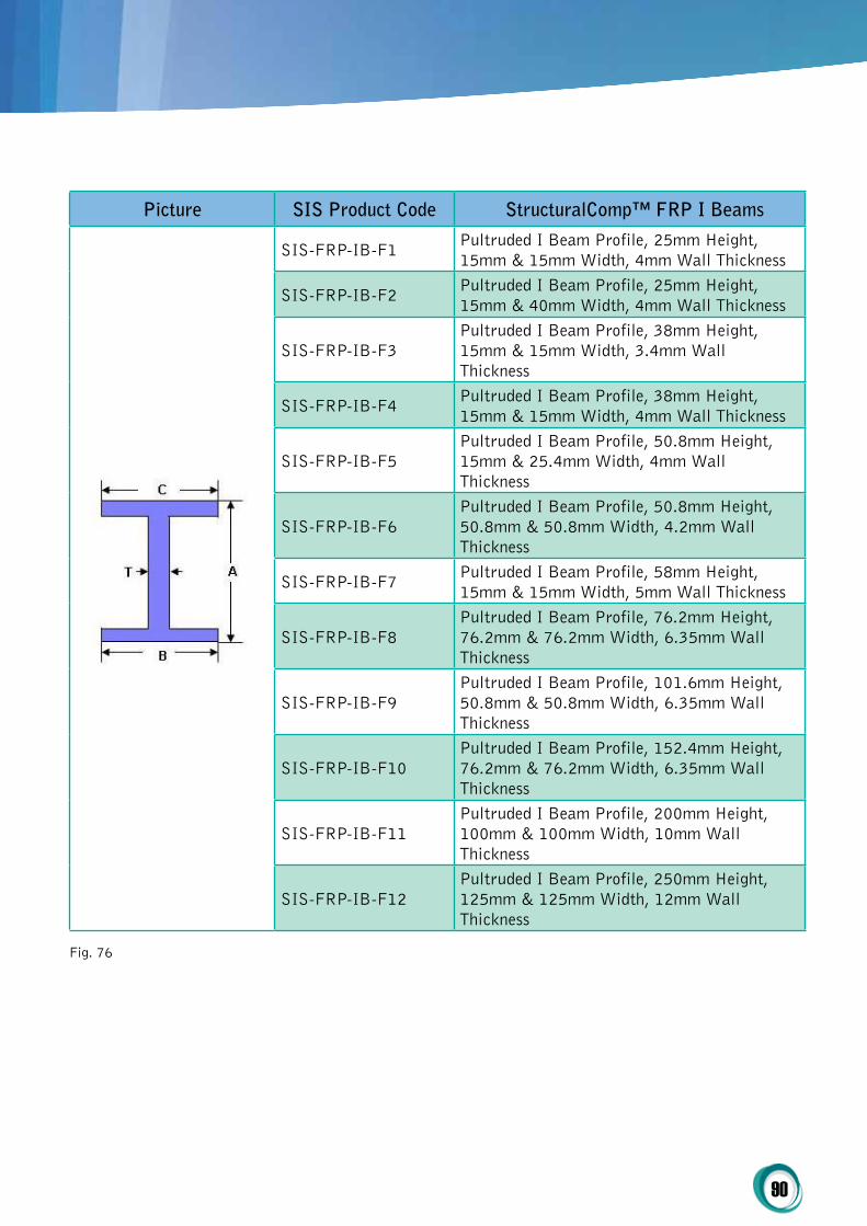
90
picture SiS product code Structuralcomp™ Frp i Beams
SIS-FRP-IB-F1 Pultruded I Beam Profile, 25mm Height, 15mm & 15mm Width, 4mm Wall Thickness
SIS-FRP-IB-F2 Pultruded I Beam Profile, 25mm Height, 15mm & 40mm Width, 4mm Wall Thickness
SIS-FRP-IB-F3Pultruded I Beam Profile, 38mm Height, 15mm & 15mm Width, 3.4mm Wall Thickness
SIS-FRP-IB-F4 Pultruded I Beam Profile, 38mm Height, 15mm & 15mm Width, 4mm Wall Thickness
SIS-FRP-IB-F5Pultruded I Beam Profile, 50.8mm Height, 15mm & 25.4mm Width, 4mm Wall Thickness
SIS-FRP-IB-F6Pultruded I Beam Profile, 50.8mm Height, 50.8mm & 50.8mm Width, 4.2mm Wall Thickness
SIS-FRP-IB-F7 Pultruded I Beam Profile, 58mm Height, 15mm & 15mm Width, 5mm Wall Thickness
SIS-FRP-IB-F8Pultruded I Beam Profile, 76.2mm Height, 76.2mm & 76.2mm Width, 6.35mm Wall Thickness
SIS-FRP-IB-F9Pultruded I Beam Profile, 101.6mm Height, 50.8mm & 50.8mm Width, 6.35mm Wall Thickness
SIS-FRP-IB-F10Pultruded I Beam Profile, 152.4mm Height, 76.2mm & 76.2mm Width, 6.35mm Wall Thickness
SIS-FRP-IB-F11Pultruded I Beam Profile, 200mm Height, 100mm & 100mm Width, 10mm Wall Thickness
SIS-FRP-IB-F12Pultruded I Beam Profile, 250mm Height, 125mm & 125mm Width, 12mm Wall Thickness
Fig. 76
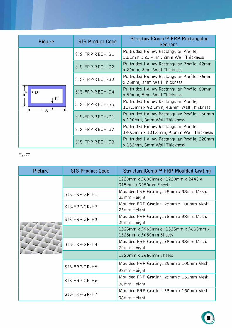
91
picture SiS product code Structuralcomp™ Frp rectangular Sections
SIS-FRP-RECH-G1Pultruded Hollow Rectangular Profile, 38.1mm x 25.4mm, 2mm Wall Thickness
SIS-FRP-RECH-G2Pultruded Hollow Rectangular Profile, 42mm x 20mm, 2mm Wall Thickness
SIS-FRP-RECH-G3Pultruded Hollow Rectangular Profile, 76mm x 26mm, 3mm Wall Thickness
SIS-FRP-RECH-G4Pultruded Hollow Rectangular Profile, 80mm x 50mm, 5mm Wall Thickness
SIS-FRP-RECH-G5Pultruded Hollow Rectangular Profile, 117.5mm x 92.1mm, 4.8mm Wall Thickness
SIS-FRP-RECH-G6Pultruded Hollow Rectangular Profile, 150mm x 100mm, 8mm Wall Thickness
SIS-FRP-RECH-G7Pultruded Hollow Rectangular Profile, 190.5mm x 101.6mm, 9.5mm Wall Thickness
SIS-FRP-RECH-G8Pultruded Hollow Rectangular Profile, 228mm x 152mm, 6mm Wall Thickness
Fig. 77
picture SiS product code Structuralcomp™ Frp Moulded grating
1220mm x 3600mm or 1220mm x 2440 or 915mm x 3050mm Sheets
SIS-FRP-GR-H1Moulded FRP Grating, 38mm x 38mm Mesh, 25mm Height
SIS-FRP-GR-H2Moulded FRP Grating, 25mm x 100mm Mesh, 25mm Height
SIS-FRP-GR-H3Moulded FRP Grating, 38mm x 38mm Mesh, 38mm Height1525mm x 3965mm or 1525mm x 3660mm x 1525mm x 3050mm Sheets
SIS-FRP-GR-H4Moulded FRP Grating, 38mm x 38mm Mesh, 25mm Height
1220mm x 3660mm Sheets
SIS-FRP-GR-H5Moulded FRP Grating, 25mm x 100mm Mesh,
38mm Height
SIS-FRP-GR-H6Moulded FRP Grating, 25mm x 152mm Mesh,
38mm Height
SIS-FRP-GR-H7Moulded FRP Grating, 38mm x 150mm Mesh,
38mm Height

92
1220mm x 3600mm or 1220mm x 2440 or
915mm x 3050mm Sheets
SIS-FRP-GR-H8Moulded FRP Grating, 50mm x 50mm Mesh,
50mm Height
1220mm x 3660mm Sheets
SIS-FRP-GR-H9Moulded FRP Grating, 50mm x 50mm Mesh,
13mm Height
SIS-FRP-GR-H10Moulded FRP Grating, 38mm x 38mm Mesh,
25mm Height
580mm x 3050mm or 580mm x 3660 Sheets
SIS-FRP-GR-H11Moulded FRP Grating, 38mm x 152mm Mesh,
38mm Height1247mm x 3087mm or 1007mm x 3007mm
Sheets
SIS-FRP-GR-H12Moulded FRP Grating, 40mm x 40mm Mesh,
25mm Height
1009mm x 3007mm Sheets
SIS-FRP-GR-H13Moulded FRP Grating, 25mm x 100mm Mesh,
25mm Height
1009mm x 3307mm Sheets
SIS-FRP-GR-H14Moulded FRP Grating, 100mm x 25mm Mesh,
25mm Height
1247mm x 3087mm Sheets
SIS-FRP-GR-H15Moulded FRP Grating, 40mm x 40mm Mesh,
40mm Height1247mm x 4047mm or 1007mm x 3007mm
Sheets
SIS-FRP-GR-H16Moulded FRP Grating, 40mm x 40mm Mesh,
40mm Height
1007mm x 4047mm Sheets
SIS-FRP-GR-H17Moulded FRP Grating, 40mm x 40mm Mesh,
40mm Height1000mm x 4038mm or 1000mm x 3000mm or
1000mm x 2000mm Sheets
SIS-FRP-GR-H18Moulded FRP Grating, 38mm x 38mm Mesh,
25mm Height
SIS-FRP-GR-H19Moulded FRP Grating, 38mm x 38mm Mesh,
30mm Height

93
Fig. 78
SIS-FRP-GR-H20Moulded FRP Grating, 38mm x 38mm Mesh,
30mm Height
1413mm x 4000mm Sheets
SIS-FRP-GR-H21Moulded FRP Grating, 38mm x 38mm - 12mm
x 12mm Mesh, 32mm Height1000mm x 4050mm or 1000mm x 3000mm or
1000mm x 2000mm Sheets
SIS-FRP-GR-H22Moulded FRP Grating, 52mm x 52mm - 19mm
x 19mm Mesh, 32mm Height
SIS-FRP-GR-H23Moulded FRP Grating, 52mm x 52mm - 19mm
x 19mm Mesh, 38mm Height
SIS-FRP-GR-H24Moulded FRP Grating, 52mm x 52mm - 18mm
x 18mm Mesh, 52mm Height
SIS-FRP-GR-H25Moulded FRP Grating, 52mm x 52mm - 18mm
x 18mm Mesh, 55mm Height
1000mm x 4038mm Sheets
SIS-FRP-GR-H26Moulded FRP Grating, 38mm x 38mm - 8mm x
8mm Mesh, 30mm Height1220mm x 3660mm or 1220mm x 2440mm or
915mm x 3050mm Sheets
SIS-FRP-GR-H27Moulded FRP Grating, 50mm x 50mm - 18mm
x 18mm Mesh, 32mm Height
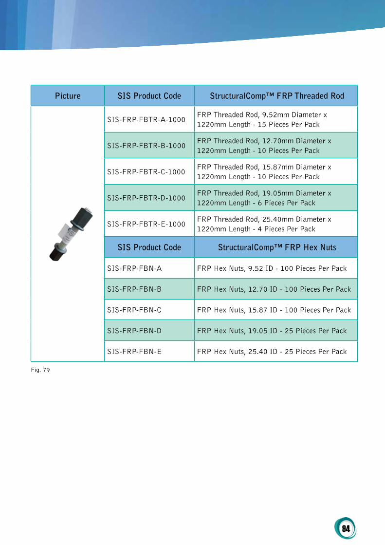
94
picture SiS product code Structuralcomp™ Frp threaded rod
SIS-FRP-FBTR-A-1000FRP Threaded Rod, 9.52mm Diameter x 1220mm Length - 15 Pieces Per Pack
SIS-FRP-FBTR-B-1000FRP Threaded Rod, 12.70mm Diameter x 1220mm Length - 10 Pieces Per Pack
SIS-FRP-FBTR-C-1000FRP Threaded Rod, 15.87mm Diameter x 1220mm Length - 10 Pieces Per Pack
SIS-FRP-FBTR-D-1000FRP Threaded Rod, 19.05mm Diameter x 1220mm Length - 6 Pieces Per Pack
SIS-FRP-FBTR-E-1000FRP Threaded Rod, 25.40mm Diameter x 1220mm Length - 4 Pieces Per Pack
SiS product code Structuralcomp™ Frp hex Nuts
SIS-FRP-FBN-A FRP Hex Nuts, 9.52 ID - 100 Pieces Per Pack
SIS-FRP-FBN-B FRP Hex Nuts, 12.70 ID - 100 Pieces Per Pack
SIS-FRP-FBN-C FRP Hex Nuts, 15.87 ID - 100 Pieces Per Pack
SIS-FRP-FBN-D FRP Hex Nuts, 19.05 ID - 25 Pieces Per Pack
SIS-FRP-FBN-E FRP Hex Nuts, 25.40 ID - 25 Pieces Per Pack
Fig. 79
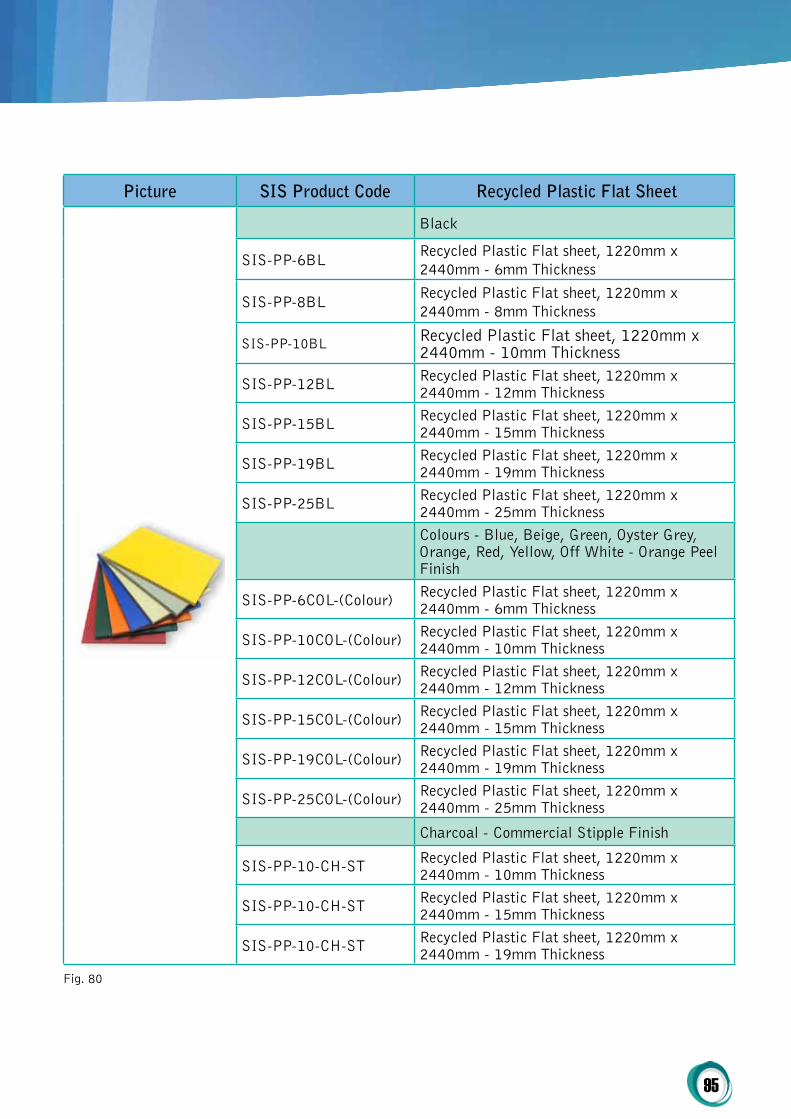
95
picture SiS product code recycled plastic Flat Sheet
Black
SIS-PP-6BL Recycled Plastic Flat sheet, 1220mm x 2440mm - 6mm Thickness
SIS-PP-8BL Recycled Plastic Flat sheet, 1220mm x 2440mm - 8mm Thickness
SIS-PP-10BL Recycled Plastic Flat sheet, 1220mm x 2440mm - 10mm Thickness
SIS-PP-12BL Recycled Plastic Flat sheet, 1220mm x 2440mm - 12mm Thickness
SIS-PP-15BL Recycled Plastic Flat sheet, 1220mm x 2440mm - 15mm Thickness
SIS-PP-19BL Recycled Plastic Flat sheet, 1220mm x 2440mm - 19mm Thickness
SIS-PP-25BL Recycled Plastic Flat sheet, 1220mm x 2440mm - 25mm Thickness Colours - Blue, Beige, Green, Oyster Grey, Orange, Red, Yellow, Off White - Orange Peel Finish
SIS-PP-6COL-(Colour) Recycled Plastic Flat sheet, 1220mm x 2440mm - 6mm Thickness
SIS-PP-10COL-(Colour) Recycled Plastic Flat sheet, 1220mm x 2440mm - 10mm Thickness
SIS-PP-12COL-(Colour) Recycled Plastic Flat sheet, 1220mm x 2440mm - 12mm Thickness
SIS-PP-15COL-(Colour) Recycled Plastic Flat sheet, 1220mm x 2440mm - 15mm Thickness
SIS-PP-19COL-(Colour) Recycled Plastic Flat sheet, 1220mm x 2440mm - 19mm Thickness
SIS-PP-25COL-(Colour) Recycled Plastic Flat sheet, 1220mm x 2440mm - 25mm Thickness
Charcoal - Commercial Stipple Finish
SIS-PP-10-CH-ST Recycled Plastic Flat sheet, 1220mm x 2440mm - 10mm Thickness
SIS-PP-10-CH-ST Recycled Plastic Flat sheet, 1220mm x 2440mm - 15mm Thickness
SIS-PP-10-CH-ST Recycled Plastic Flat sheet, 1220mm x 2440mm - 19mm Thickness
Fig. 80
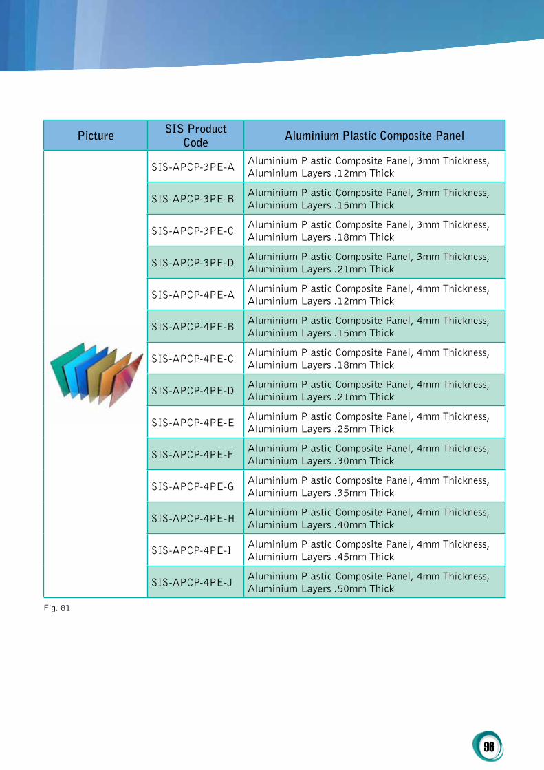
96
picture SiS product code Aluminium plastic composite panel
SIS-APCP-3PE-A Aluminium Plastic Composite Panel, 3mm Thickness, Aluminium Layers .12mm Thick
SIS-APCP-3PE-B Aluminium Plastic Composite Panel, 3mm Thickness, Aluminium Layers .15mm Thick
SIS-APCP-3PE-C Aluminium Plastic Composite Panel, 3mm Thickness, Aluminium Layers .18mm Thick
SIS-APCP-3PE-D Aluminium Plastic Composite Panel, 3mm Thickness, Aluminium Layers .21mm Thick
SIS-APCP-4PE-A Aluminium Plastic Composite Panel, 4mm Thickness, Aluminium Layers .12mm Thick
SIS-APCP-4PE-B Aluminium Plastic Composite Panel, 4mm Thickness, Aluminium Layers .15mm Thick
SIS-APCP-4PE-C Aluminium Plastic Composite Panel, 4mm Thickness, Aluminium Layers .18mm Thick
SIS-APCP-4PE-D Aluminium Plastic Composite Panel, 4mm Thickness, Aluminium Layers .21mm Thick
SIS-APCP-4PE-E Aluminium Plastic Composite Panel, 4mm Thickness, Aluminium Layers .25mm Thick
SIS-APCP-4PE-F Aluminium Plastic Composite Panel, 4mm Thickness, Aluminium Layers .30mm Thick
SIS-APCP-4PE-G Aluminium Plastic Composite Panel, 4mm Thickness, Aluminium Layers .35mm Thick
SIS-APCP-4PE-H Aluminium Plastic Composite Panel, 4mm Thickness, Aluminium Layers .40mm Thick
SIS-APCP-4PE-I Aluminium Plastic Composite Panel, 4mm Thickness, Aluminium Layers .45mm Thick
SIS-APCP-4PE-J Aluminium Plastic Composite Panel, 4mm Thickness, Aluminium Layers .50mm Thick
Fig. 81
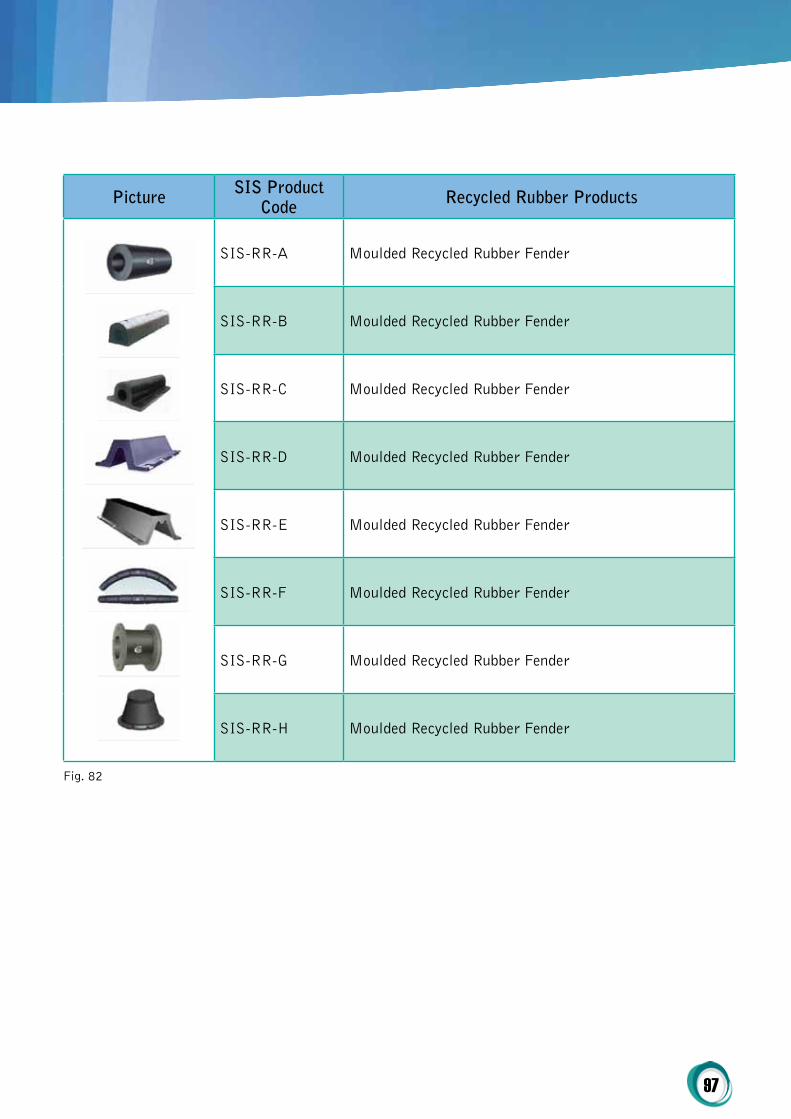
97
picture SiS product code recycled rubber products
SIS-RR-A Moulded Recycled Rubber Fender
SIS-RR-B Moulded Recycled Rubber Fender
SIS-RR-C Moulded Recycled Rubber Fender
SIS-RR-D Moulded Recycled Rubber Fender
SIS-RR-E Moulded Recycled Rubber Fender
SIS-RR-F Moulded Recycled Rubber Fender
SIS-RR-G Moulded Recycled Rubber Fender
SIS-RR-H Moulded Recycled Rubber Fender
Fig. 82

98
pricE NotE For proDUctS BELoWSIS offers container pricing on products below - contact us for further information
picture SiS product code recycled plastic Flat Sheet
SIS-RR-BLDMoulded Recycled Rubber / Recycled Plastic Traffic Bollard - 1150mm x Ø25mm
SIS-RR-TCMoulded Recycled Rubber / Recycled Plastic Traffic Cone - 750mm
SIS-RR-PARecycled Rubber Parking Aid - 1650mm x 140mm x 100mm
SIS-RR-SHRecycled Rubber Speed Humps - 500mm x 350mm x 50mm Black / Yellow Section
Fig. 83

99
general
1. What is SiS Structuralcomp™ Frp?
StructuralComp™ FRP is Fibre Reinforced Polymer (plastic) that is reinforced with glass or carbon fibre. The primary function of fibre reinforcement is to carry load along the length of the fibre and to provide strength and stiffness in one direction. SIS StructuralComp™ FRP represents a class of materials that falls into a category referred to as composite materials. Composite materials consist of two or more materials that retain their respective chemical and physical characteristics when combined together.
2. Why is Structuralcomp™ Frp better than traditional construction materials?
StructuralComp™ FRP composites are different from traditional construction materials like steel or aluminium. StructuralComp™ FRP composites are anisotropic (properties apparent in the direction of applied load) whereas steel or aluminium is isotropic (uniform properties in all directions, independent of applied load). Therefore StructuralComp™ FRP composites properties are directional, meaning that the best mechanical properties are in the direction of the fibre placement.
3. What is Structuralcomp™ Frp’s environmental impact?
StructuralComp™ FRP is environmentally friendly as FRP products produce fewer air and water emissions, consumes less energy and emits less greenhouse gas, leading to both a reduced environmental impact and a lower
carbon footprint. Since FRP does not corrode or deteriorate, it can be recycled. More importantly, however, virgin production of FRP usually has less environmental impact than even recycling alternate materials, such as steel and aluminium.
pricing
4. how does Structuralcomp™ Frp compare to steel in price?
StructuralComp™ FRP materials are generally more expensive than steel when comparing material costs. However, when factoring in installation, handling, transportation and other associated expenses, the total installed cost of FRP is more competitive to steel.
5. how does Structuralcomp™ Frp compare to stainless steel in price?
StructuralComp™ FRP materials are normally less than the cost of stainless steel.
6. how does Structuralcomp™ Frp compare to wood in price?
StructuralComp™ FRP materials cannot compete with wood on price alone. Customers considering using FRP in place of wood should evaluate the strength, rot resistance and overall performance requirements for the application and choose the best material accordingly.
7. What information is needed to get a Structuralcomp™ design and cost estimate for a bridge?
A: SIS just needs bridge size, load requirements and support spacing to provide an initial design (depth, weight) and cost (+/- 10%). If the
SIS Product FAQs

100
support spacing is undecided, we will provide an engineered solution.
technical
8. can SiS provide certified drawings by an Engineer?
A: Yes. We have in-house engineers in Australia to certify all drawings we provide. SIS also has a worldwide network of engineering companies for international projects.
9. Does Structuralcomp™ Frp corrode?
StructuralComp™ FRP does not corrode - FRP structural products are corrosion resistant to almost all chemicals. In many structural applications where wood rots and metals corrode, FRP products will last indefinitely with little or no maintenance. The applications can be as diverse as water parks, water and sewage plants and coastal areas, in fact anywhere where water (either salt water or fresh water) is present, or where corrosive chemical solutions and or vapours are present. FRP is used extensively in processing and chemical plants. Pultruded FRP products will endure an extremely long life with very little maintenance.
10. how strong is Structuralcomp™ Frp?
Generally speaking, StructuralComp™ structural shapes have a high strength-to-weight ratio and kilos for kilo are stronger than steel longitudinally. FRP products distribute impact loads to prevent surface damage even in sub-zero temperatures and will not permanently deform under impact. Engineers and Designers in the future will use StructuralComp™ FRP to design and build what was virtually impossible before FRP.
11. how heavy is Structuralcomp™ Frp?
StructuralComp™ FRP materials are lightweight. Generally on an equal volume basis, pultruded
FRP will weigh only 25% of the weight of steel and 70% of the weight of aluminium. This feature can significantly impact installation costs, reduce the risk for injury and result in less structural support from foundations or supporting structures.
12. is Structuralcomp™ electrically safe?
Yes, StructuralComp™ FRP is extremely low in electrical conductivity. Nonconductive products provide significant safety benefits in many applications such as those found in electrical switch board rooms and sub stations.
13. is Structuralcomp™ Frp thermally conductive?
StructuralComp™ FRP has a low ‘U’ value and is low in thermal conductivity and FRP products do not expand or contract like metals. This feature can provide a significant degree of thermal insulation. It also can be a safety feature. For example, if one part of an FRP product is extremely hot, individuals who touch the structure away from the heat source won’t be burned.
14. is Structuralcomp™ Frp compatible with Wi-Fi?
StructuralComp™ FRP is EMI / RFI Transparent - material that is transparent to radar and radio waves. This feature can benefit applications such as Wi-Fi, antenna and cellular shielding. FRP products are suitable for communication installations and server rooms.
15. is Structuralcomp™ Frp flammable?
StructuralComp™ FRP is fire resistant and can be provided with a fire resistant additive that virtually eliminates the flame and smoke components from the polymer. StructuralComp™ FRP fire retardant will comply with AS 1530.4, BS 1979 and ASTM E-84 and ASTM D-635.

101
StructuralComp™ FRP can be used in buildings with confidence. We manufacture many different products that are suitable for use where there is a calculated fire risk.
16. how does Structuralcomp™ Frp compare to steel in strength?
Please contact SIS customer service for a comparison data sheet.
17. how does Structuralcomp™ Frp compare to wood in strength?
Please contact SIS customer service for a comparison data sheet.
18. how does Structuralcomp™ Frp handle hot and cold temperatures?
Temperatures must be taken into consideration during the structural design process. Refer to the SIS Design Manual for a chart showing changes in mechanical properties as the temperatures reach 50 degrees Celsius and higher. Cold temperatures are generally of little concern unless below -40 degrees Celsius.
19. What is the service life of Structuralcomp™ Frp materials?
The service life of any particular product depends on the application in which it is installed. Generally speaking, StructuralComp™ service life is beyond 40 years.
20. Does Structuralcomp™ Frp have UV protection?
The resins, coatings, and wear surfaces that we utilize are extremely resistant to UV rays. These materials are designed specifically for direct sunlight exposure.
21.how do i fabricate Structuralcomp™ Frp products?
StructuralComp™ FRP products can be cut,
drilled, and otherwise fabricated using standard
carpenter’s tools. Carbide blades and drill bits
are recommended to facilitate the task and
extend the life of the blade or bit.
22. can SiS provide pre-engineered and
fabricated materials?
Yes, SIS has in-house engineers, estimators,
drafters and fabrication services available. The
SIS Design Manual is available to assist external
engineers in the design/built process.
transport
23. how are my Structuralcomp™ Frp products
delivered?
SIS has distribution facilities in all Australian
capital cities. SIS FRP products are manufactured
in North America and China. We can therefore
land your orders into the closest sea port in
Australia to your project at much better rates
than trucking the product around Australia. This
also applies to international deliveries.
Lead times
24. What is your lead time?
Lead times vary; stocked items typically have
a lead time of 48 hours or less. If the item is
not stocked, please contact Customer Service to
inquire about its lead time.

V4.3 - Release Date 01.03.14
SISCo-FCTM SYSTEMCOMPOSITE FIXINGS
Threaded Rod & Flanged Hex NutsPart #SIS-TR Part #SIS-FHN
Annexure 1

www.sisau.com.au - 1300 261 074 104
COPYRIGHT 2013 – Sustainable Infrastructure Systems (Aust) Pty Ltd
TRADE MARKS
SISCo-FC™, CoreSpan™ and StructuralComp™ are registered trademarks used under licence by Sustainable Infrastructure Systems (Aust) Pty Ltd. Licence permission granted by Sustainable Infrastructure Systems (Aust) Pty Ltd
PATENTS / PATENTS PENDING
Parts of the SISCo-FC™ System are protected by either patents or patents pending. Individual components are protected by either patents or patents pending. Fixing methodology is protected by patents or patents pending.
All SISCo-FC™ System composite fixings are manufactured in the United States of America

www.sisau.com.au - 1300 261 074 105
Most common hardware fixings are available from SIS in various composites, although it is our threaded rod and nuts that continues to replace more traditional materials throughout Australia, North America and Europe than any other product. SISCo-FC™ threaded rod is manufactured using only premium grade vinyl ester (VE) resins and UV inhibitors. Pultrusion results in the production and supply of one of the world’s strongest and most durable fixing products available today.
SISCo-FC™ Flanged Hex Nuts are manufactured from Isoplast 40% long glass fibre engineering thermoplastic polyurethane resin via a wind out moulding process. These resins are high strength,
chemical resistant resins that combine the toughness and dimensional stability of amorphous resins with the chemical resistance of crystalline materials.
Features of SISCo-FC™ Flanged Hex Nuts and Threaded Rod Are:
1) High Strength2) Corrosion Resistant to Many Chemicals3) Light Weight – Weighs Nearly 80% Less
than Steel 4) Electrically Non Conductive5) Non Metallic6) Provides a Lower Life Cycle Cost7) Non Leaching8) Dimensionally Stable
Sizes Available - Threaded Rod
SIS CODE DIAMETER THREAD LENGTH
SIS-FC-TR-A 3/8 (9.5mm) 16 UNC Up to 8ft (2.4m)
SIS-FC-TR-B 1/2 (12.7mm) 13 UNC Up to 8ft (2.4m)
SIS-FC-TR-C 5/8 (15.9mm) 11 UNC Up to 8ft (2.4m)
SIS-FC-TR-D 3/4 (19.0mm) 10 UNC Up to 8ft (2.4m)
SIS-FC-TR-E 1 (25.4mm) 8 UNC Up to 8ft (2.4m)
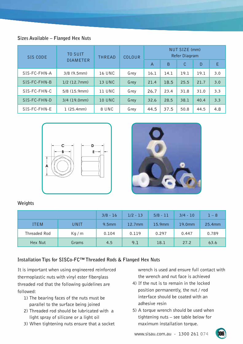
www.sisau.com.au - 1300 261 074 106
Sizes Available – Flanged Hex Nuts
SIS CODETO SUIT DIAMETER
THREAD COLOUR
NUT SIZE (mm) Refer Diagram
A B C D E
SIS-FC-FHN-A 3/8 (9.5mm) 16 UNC Grey 16.1 14.1 19.1 19.1 3.0
SIS-FC-FHN-B 1/2 (12.7mm) 13 UNC Grey 21.4 18.5 25.5 21.7 3.0
SIS-FC-FHN-C 5/8 (15.9mm) 11 UNC Grey 26.7 23.4 31.8 31.0 3.3
SIS-FC-FHN-D 3/4 (19.0mm) 10 UNC Grey 32.6 28.5 38.1 40.4 3.3
SIS-FC-FHN-E 1 (25.4mm) 8 UNC Grey 44.5 37.5 50.8 44.5 4.8
Weights
3/8 - 16 1/2 - 13 5/8 - 11 3/4 - 10 1 – 8
ITEM UNIT 9.5mm 12.7mm 15.9mm 19.0mm 25.4mm
Threaded Rod Kg / m 0.104 0.119 0.297 0.447 0.789
Hex Nut Grams 4.5 9.1 18.1 27.2 63.6
Installation Tips for SISCo-FC™ Threaded Rods & Flanged Hex Nuts
It is important when using engineered reinforced thermoplastic nuts with vinyl ester fiberglass threaded rod that the following guidelines are followed:
1) The bearing faces of the nuts must be parallel to the surface being joined
2) Threaded rod should be lubricated with a light spray of silicone or a light oil
3) When tightening nuts ensure that a socket
wrench is used and ensure full contact with the wrench and nut face is achieved
4) If the nut is to remain in the locked position permanently, the nut / rod interface should be coated with an adhesive resin
5) A torque wrench should be used when tightening nuts – see table below for maximum installation torque.

www.sisau.com.au - 1300 261 074 107
Ultimate Torque Table
SIZE ULTIMATE TORQUE STRENGTH MAXIMUM TORQUE
3/8 (9.5mm) 10.84Nm 5.42Nm
1/2 (12.7mm) 24.40Nm 12.20Nm
5/8 (15.9mm) 47.45Nm 23.72Nm
3/4 (19.0mm) 67.71Nm 33.85Nm
1 (25.4mm) 149.14Nm 74.57Nm
Typical Properties of SISCo-FC™ Threaded Rod & Nuts
Value (Diameter – Threads Per Inch)
3/8 - 16 1/2 - 13 5/8 - 11 3/4 - 10 1 – 8
PROPERTIES ASTM UNITS 9.5mm 12.7mm 15.9mm 19.0mm 25.4mm
Ultimate Transverse Shear (Double Shear)
B-565 N 18,680 30,240 44,480 59,600 106,750
Longitudinal Compressive Strength
D-695 MPa 344 344 344 344 344
Flexural Strength D-790 MPa 482 482 482 482 482
Flexural Modulus D-790 GPa 17.2 17.2 17.2 17.2 17.2
Flammability D-635 Self Extinguishing For All
Fire Retardant E-84 Class 1
Water Absorption(24hr Immersion)
D-570 % Max. 0.8 0.8 0.8 0.8 0.8
Longitudinal Coefficient of Thermal Expansion
D-69610-6 mm/mm/ C°
11 11 11 11 11
Ultimate Thread Shear (Fiberglass Nut)
---- N 5,337 10,670 16,010 17,790 36,470
Ultimate Torque Strength (Fiberglass Nut)
---- N/M 10 21 47 67 149

www.sisau.com.au - 1300 261 074 108
Typical Properties of 101 LGF40 BLK Engineering Thermoplastic Polyurethane Resin (Nuts – Raw Form)
PROPERTIES ASTM UNITS VALUE
Mould Shrinkage D-955 mm/mm 0.001
Water Absorption (24hrs @ 23°c) D-570 % 0
Specific Gravity D-792 1.51 No.
Tensile Strength at Yield D-638 MPa 186
Tensile Strength at Break D-638 MPa 186
Elongation at Yield D-638 % 2
Elongation at Break D-638 % 2
Tensile Modulus D-638 MPa 10,000
Flexural Strength D-790 MPa 248
Flexural Modulus D-790 MPa 9,600
Izod Impact Strength (Notched, 23°c) D-256 J/m 320
Izod Impact Strength (Notched, -40°c) D-256 J/m 320
Vicat Temperature D-1525 °C 186
Coefficient of Linear Thermal Expansion D-696 10-5 mm/mm/°C 1.4

www.sisau.com.au - 1300 261 074 109
Typical Properties of Glass Reinforced Vinyl Ester (Threaded Rod – Raw Form)
PROPERTIES ASTM UNITS VALUE
Barcol Hardness D-2583 ---- 45
Tensile Strength, Ultimate (Lengthwise) D-638 207 MPa
Tensile Strength, Ultimate (Crosswise) D-638 48.3 MPa
Tensile Modulus (Lengthwise) D-638 17.2 GPa
Tensile Modulus (Crosswise) D-638 5.52 GPa
Flexural Modulus (Lengthwise) D-790 12.4 GPa
Flexural Modulus (Crosswise) D-790 5.52 GPa
Flexural Strength (Lengthwise) D-790 207 MPa
Flexural Strength (Crosswise) D-790 68.9 MPa
Compressive Strength (Lengthwise) D-635 207 MPa
Compressive Strength (Crosswise) D-635 103 MPa
Compressive Modulus (Lengthwise) D-635 17.2 GPa
Compressive Modulus (Crosswise) D-635 6.89 GPa
Shear Modulus ---- 3.1 GPa
Shear Strength (Punch Shear) D-732 68.9 MPa
Shear Strength (Short Beam Shear) D-2344 31 MPa
Izod Impact, Notched (Lengthwise) D-256 13.3 J/cm
Izod Impact, Notched (Crosswise) D-256 2.14 J/cmDielectric Constant (Perpendicular to
Laminate Face)D-150 5 60 Hz
Dielectric Strength (Perpendicular to Laminate Face)
D-149 7.87 kV/mm
Dielectric Strength (Lengthwise) D-149 1.38 kV/mm
Arc Resistance (Lengthwise) D-495 120 Sec
Flame Spread Index (Tunnel Test) E-84 Max 25 ----
Flammability D-635 Non Burning
Density D-792 1.72-1.94 g/cc
Water Absorption 24hrs, ASTM Max 0.45%
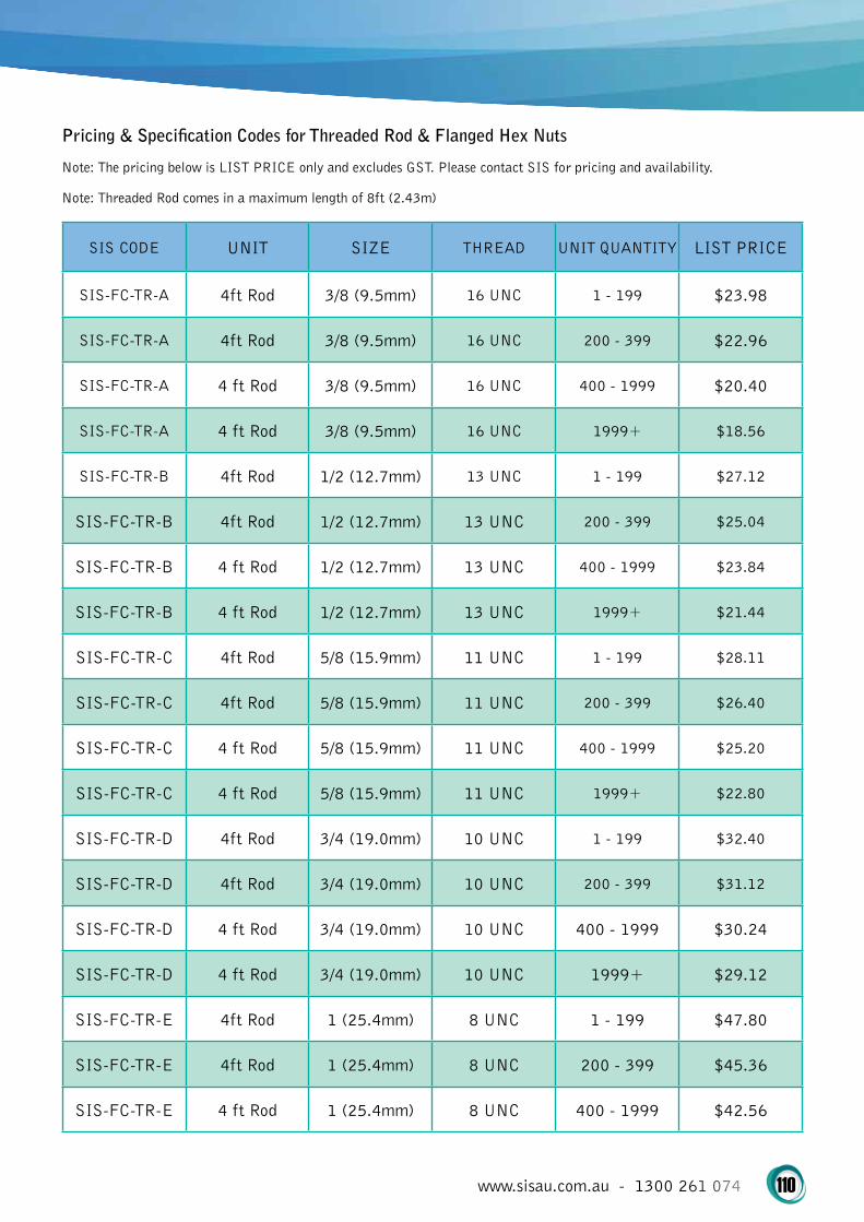
www.sisau.com.au - 1300 261 074 110
Pricing & Specification Codes for Threaded Rod & Flanged Hex Nuts
Note: The pricing below is LIST PRICE only and excludes GST. Please contact SIS for pricing and availability.
Note: Threaded Rod comes in a maximum length of 8ft (2.43m)
SIS CODE UNIT SIZE THREAD UNIT QUANTITY LIST PRICE
SIS-FC-TR-A 4ft Rod 3/8 (9.5mm) 16 UNC 1 - 199 $23.98
SIS-FC-TR-A 4ft Rod 3/8 (9.5mm) 16 UNC 200 - 399 $22.96
SIS-FC-TR-A 4 ft Rod 3/8 (9.5mm) 16 UNC 400 - 1999 $20.40
SIS-FC-TR-A 4 ft Rod 3/8 (9.5mm) 16 UNC 1999+ $18.56
SIS-FC-TR-B 4ft Rod 1/2 (12.7mm) 13 UNC 1 - 199 $27.12
SIS-FC-TR-B 4ft Rod 1/2 (12.7mm) 13 UNC 200 - 399 $25.04
SIS-FC-TR-B 4 ft Rod 1/2 (12.7mm) 13 UNC 400 - 1999 $23.84
SIS-FC-TR-B 4 ft Rod 1/2 (12.7mm) 13 UNC 1999+ $21.44
SIS-FC-TR-C 4ft Rod 5/8 (15.9mm) 11 UNC 1 - 199 $28.11
SIS-FC-TR-C 4ft Rod 5/8 (15.9mm) 11 UNC 200 - 399 $26.40
SIS-FC-TR-C 4 ft Rod 5/8 (15.9mm) 11 UNC 400 - 1999 $25.20
SIS-FC-TR-C 4 ft Rod 5/8 (15.9mm) 11 UNC 1999+ $22.80
SIS-FC-TR-D 4ft Rod 3/4 (19.0mm) 10 UNC 1 - 199 $32.40
SIS-FC-TR-D 4ft Rod 3/4 (19.0mm) 10 UNC 200 - 399 $31.12
SIS-FC-TR-D 4 ft Rod 3/4 (19.0mm) 10 UNC 400 - 1999 $30.24
SIS-FC-TR-D 4 ft Rod 3/4 (19.0mm) 10 UNC 1999+ $29.12
SIS-FC-TR-E 4ft Rod 1 (25.4mm) 8 UNC 1 - 199 $47.80
SIS-FC-TR-E 4ft Rod 1 (25.4mm) 8 UNC 200 - 399 $45.36
SIS-FC-TR-E 4 ft Rod 1 (25.4mm) 8 UNC 400 - 1999 $42.56
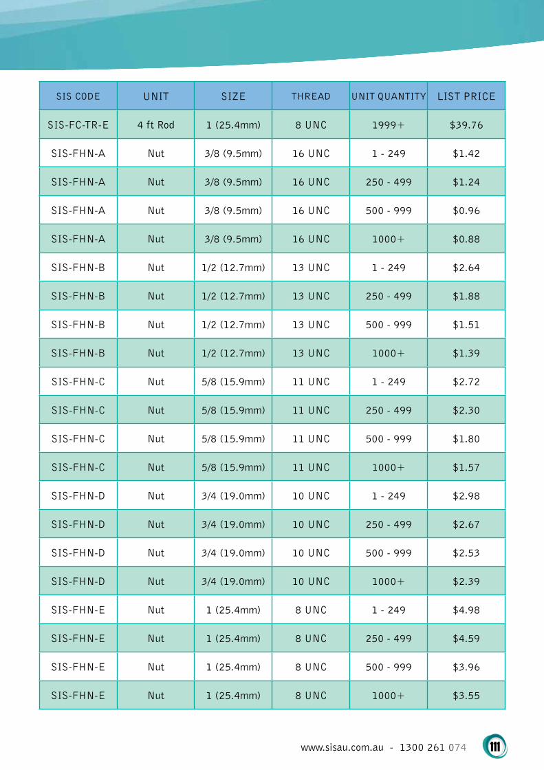
www.sisau.com.au - 1300 261 074 111
SIS CODE UNIT SIZE THREAD UNIT QUANTITY LIST PRICE
SIS-FC-TR-E 4 ft Rod 1 (25.4mm) 8 UNC 1999+ $39.76
SIS-FHN-A Nut 3/8 (9.5mm) 16 UNC 1 - 249 $1.42
SIS-FHN-A Nut 3/8 (9.5mm) 16 UNC 250 - 499 $1.24
SIS-FHN-A Nut 3/8 (9.5mm) 16 UNC 500 - 999 $0.96
SIS-FHN-A Nut 3/8 (9.5mm) 16 UNC 1000+ $0.88
SIS-FHN-B Nut 1/2 (12.7mm) 13 UNC 1 - 249 $2.64
SIS-FHN-B Nut 1/2 (12.7mm) 13 UNC 250 - 499 $1.88
SIS-FHN-B Nut 1/2 (12.7mm) 13 UNC 500 - 999 $1.51
SIS-FHN-B Nut 1/2 (12.7mm) 13 UNC 1000+ $1.39
SIS-FHN-C Nut 5/8 (15.9mm) 11 UNC 1 - 249 $2.72
SIS-FHN-C Nut 5/8 (15.9mm) 11 UNC 250 - 499 $2.30
SIS-FHN-C Nut 5/8 (15.9mm) 11 UNC 500 - 999 $1.80
SIS-FHN-C Nut 5/8 (15.9mm) 11 UNC 1000+ $1.57
SIS-FHN-D Nut 3/4 (19.0mm) 10 UNC 1 - 249 $2.98
SIS-FHN-D Nut 3/4 (19.0mm) 10 UNC 250 - 499 $2.67
SIS-FHN-D Nut 3/4 (19.0mm) 10 UNC 500 - 999 $2.53
SIS-FHN-D Nut 3/4 (19.0mm) 10 UNC 1000+ $2.39
SIS-FHN-E Nut 1 (25.4mm) 8 UNC 1 - 249 $4.98
SIS-FHN-E Nut 1 (25.4mm) 8 UNC 250 - 499 $4.59
SIS-FHN-E Nut 1 (25.4mm) 8 UNC 500 - 999 $3.96
SIS-FHN-E Nut 1 (25.4mm) 8 UNC 1000+ $3.55
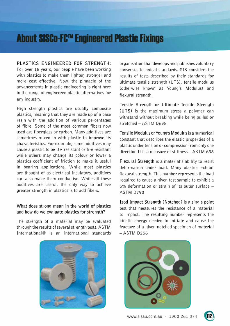
www.sisau.com.au - 1300 261 074 112
PLASTICS ENGINEERED FOR STRENGTH: For over 18 years, our people have been working with plastics to make them lighter, stronger and more cost effective. Now, the pinnacle of the advancements in plastic engineering is right here in the range of engineered plastic alternatives for any industry.
High strength plastics are usually composite plastics, meaning that they are made up of a base resin with the addition of various percentages of fibre. Some of the most common fibers now used are fiberglass or carbon. Many additives are sometimes mixed in with plastic to improve its characteristics. For example, some additives may cause a plastic to be UV resistant or fire resistant while others may change its colour or lower a plastics coefficient of friction to make it useful in bearing applications. While most plastics are thought of as electrical insulators, additives can also make them conductive. While all these additives are useful, the only way to achieve greater strength in plastics is to add fibers.
What does strong mean in the world of plastics and how do we evaluate plastics for strength?
The strength of a material may be evaluated through the results of several strength tests. ASTM International® is an international standards
organisation that develops and publishes voluntary consensus technical standards. SIS considers the results of tests described by their standards for ultimate tensile strength (UTS), tensile modulus (otherwise known as Young’s Modulus) and flexural strength.
Tensile Strength or Ultimate Tensile Strength (UTS) is the maximum stress a polymer can withstand without breaking while being pulled or stretched – ASTM D638
Tensile Modulus or Young’s Modulus is a numerical constant that describes the elastic properties of a plastic under tension or compression from only one direction It is a measure of stiffness – ASTM 638
Flexural Strength is a material’s ability to resist deformation under load. Many plastics exhibit flexural strength. This number represents the load required to cause a given test sample to exhibit a 5% deformation or strain of its outer surface – ASTM D790
Izod Impact Strength (Notched) is a single point test that measures the resistance of a material to impact. The resulting number represents the kinetic energy needed to initiate and cause the fracture of a given notched specimen of material – ASTM D256

www.sisau.com.au - 1300 261 074 113
High Strength Plastics Reference Chart
MATERIALTENSILE STRENGTH
(MPa)
TENSILE MODULUS
(MPa)
FLEXURALMODULUS (MPa)
IZOD IMPACT STRENGTH
(J/m)
G10 / FR4 310LW: 24131CW: 20684
LW: 400CW: 345
641
Nylon 6/6 30% Glass Filled 155 8274 179 107
PAI Unfilled 152 4480 241 123
PAI 30 % Glass Filled 221 14500 333 80
PAI 30% Carbon Filled 221 16500 350 48
PARA 30% Glass Filled 190 11500 360 70
PARA 30% Carbon Filled 250 26000 285 59
PEEK 30% Glass Filled 165 8963 193 96
PEEK 30% Carbon Filled 138 7584 172 55
PC 20% Glass Filled 110 2206 131 107
PEI 30% Glass Filled 138 6205 207 107
POM 30% Glass Filled 110 9653 165 40
PPS 30% Glass Filled 152 13100 200 90
PPS 30% Carbon Filled 193 25512 269 31
TPU 40% Glass Filled 186 12000 310 427

www.sisau.com.au - 1300 261 074 114
Why Do We Add Fibers to Already Strong Plastics?
Here are some examples of performance increasing when we have added glass or carbon fibers to already strong plastics. Other benefits of these materials are also mentioned.
All values are expressed in MPa.
G10/FR4: This material is made of woven fiberglass cloth and an epoxy resin. It can be made as either a laminate or through a moulding process. G10/FR4 has a tensile strength (UTS) of 310, which makes it stronger than structural steel at 276 and is one of the strongest plastic materials available. Because G10/FR4 is anisotropic or directionally dependent, it has both LW (Length Wise) and CW (Cross Wise) values for tensile modulus and flexural modulus. Additionally, G10/FR4 is fire resistant, UV resistant and water proof.
Polyamide Nylon 6/6, 30% Glass Filled: Perhaps the best known composite plastic. Unfilled Nylon 6/6 has a tensile strength of 82 but adding 30% glass fiber increases this to 155. Additionally the tensile modulus or Young’s Modulus goes from 2558 unfilled to 8274 for 30% glass filled. The flexural strength for the unfilled grade is 103 compared to 179 for 30% glass filled. Grades are also available that are fire and UV resistant and also resistant to organic solvents such as petrol and kerosene. Nylon 6/6 30% glass filled offers increased strength for relatively low cost.
Polyarylamide, PARA 30% Glass Filled & PARA 30% Carbon Filled: This polymer is not commonly sold in an unfilled grade. It can be fibre filled up to 60% with glass, carbon and mineral fibers or a combination thereof. PARA 30% glass filled has a tensile strength (UTS) of 190 and PARA carbon filled is 250. The tensile modulus for 30% glass filled is 11500 while for 30% carbon fibre it is 26000 (ISO527-2). Flexural strength for the 2 grades are 360 and 285 respectively. PARA has a high quality surface finish and can be painted and chromed for high end applications.
Polyamide Imide, PAI Unfilled, PARI 30% Glass Filled & 30% Carbon Filled: PAI is one of the few polymers that has significant strength in the unfilled grade. The UTS of unfilled PAI is 152 while the UTS of both the 30% glass filled and the 30% carbon filled increases to 221. The tensile modulus or stiffness of unfilled PAI is 480 but this increases to 14500 for PAI 30% glass filled and 16500 for PAI 30% carbon filled. Flexural strength is 241 for the unfilled grade and 333 for the PAI 30% glass filled and 350 for PAI 30% carbon filled grade. This makes polyamide imide the strongest thermoplastic currently available.
Polycarbonate (PC) 20% Glass Filled: Polycarbonate is not one of the strongest composites, however, if the characteristics of PC are required and more strength than the unfilled grade will provide are necessary, the 20% glass filled composite may be the answer. Tensile strength of the unfilled grade is 69 and increases to 110 with the addition of 20% glass fibre. Stiffness (tensile modulus) almost triples at 2206 for the unfilled grade to 5929 for the 20% glass composite. The ability for the material to avoid deformation under load (flexural strength) goes from 90 to 131. Unfilled PC is optically clear as well as UV resistant.
Polyetherimide (PEI 30% Glass Filled): Unfilled PEI has a tensile strength of 115 but the strength of PEI goes up when 30% glass is added to 138. Tensile modulus (stiffness) is 3309 for the unfilled grade but almost doubles to 6205 for the 30% glass filled composite. Flexural strength increases from 138 to 207 and the flexural modulus of 3447 for the unfilled resin increases to 6550 for 30% glass filled. PEI is also microwave clear, has high heat resistance and good chemical resistance. It is also fire resistant and virtually smoke free.
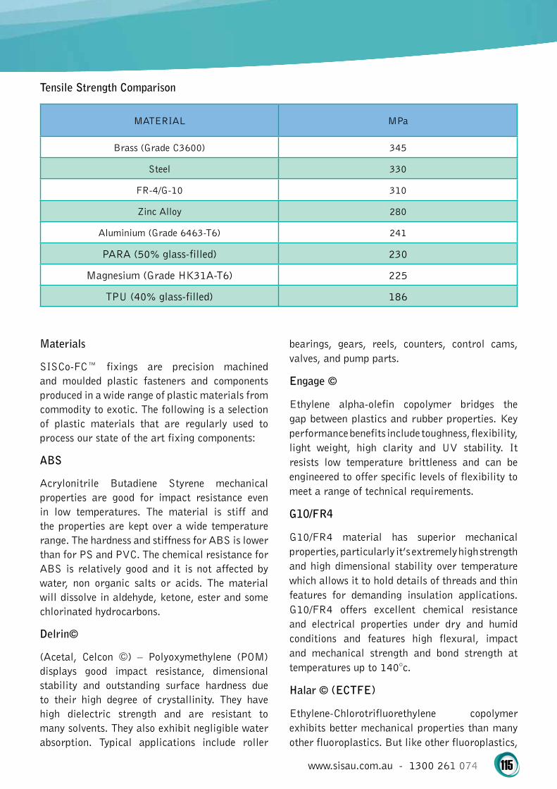
www.sisau.com.au - 1300 261 074 115
Tensile Strength Comparison
MATERIAL MPa
Brass (Grade C3600) 345
Steel 330
FR-4/G-10 310
Zinc Alloy 280
Aluminium (Grade 6463-T6) 241
PARA (50% glass-filled) 230
Magnesium (Grade HK31A-T6) 225
TPU (40% glass-filled) 186
Materials
SISCo-FC™ fixings are precision machined and moulded plastic fasteners and components produced in a wide range of plastic materials from commodity to exotic. The following is a selection of plastic materials that are regularly used to process our state of the art fixing components:
ABS
Acrylonitrile Butadiene Styrene mechanical properties are good for impact resistance even in low temperatures. The material is stiff and the properties are kept over a wide temperature range. The hardness and stiffness for ABS is lower than for PS and PVC. The chemical resistance for ABS is relatively good and it is not affected by water, non organic salts or acids. The material will dissolve in aldehyde, ketone, ester and some chlorinated hydrocarbons.
Delrin©
(Acetal, Celcon ©) – Polyoxymethylene (POM) displays good impact resistance, dimensional stability and outstanding surface hardness due to their high degree of crystallinity. They have high dielectric strength and are resistant to many solvents. They also exhibit negligible water absorption. Typical applications include roller
bearings, gears, reels, counters, control cams, valves, and pump parts.
Engage ©
Ethylene alpha-olefin copolymer bridges the gap between plastics and rubber properties. Key performance benefits include toughness, flexibility, light weight, high clarity and UV stability. It resists low temperature brittleness and can be engineered to offer specific levels of flexibility to meet a range of technical requirements.
G10/FR4
G10/FR4 material has superior mechanical properties, particularly it’s extremely high strength and high dimensional stability over temperature which allows it to hold details of threads and thin features for demanding insulation applications. G10/FR4 offers excellent chemical resistance and electrical properties under dry and humid conditions and features high flexural, impact and mechanical strength and bond strength at temperatures up to 140°c.
Halar © (ECTFE)
Ethylene-Chlorotrifluorethylene copolymer exhibits better mechanical properties than many other fluoroplastics. But like other fluoroplastics,

www.sisau.com.au - 1300 261 074 116
its flame retardation, chemical resistance and low dielectric constant remain constant over a wide temperature range. These qualities make it suitable for use in such products as electrical insulation, monofilament, tank linings, housings and electrical components. It may be usefully employed at temperatures from the cryogenic range to about 160°c.
Isoplast™
Impastmodified urethane resins are high tensile strength, chemically resistant resins originally developed for medical use. They are available in long glass fibre-filled grades. Isoplast combines the toughness and dimensional stability of amorphous resins with the chemical resistance of crystalline materials. The long fibre reinforced grades are strong enough to replace some metals in load bearing applications.
IXEF
1521 is a 50% glass-fibre reinforced, fire resistant polyarylaminde which exhibits high strength and stiffness, outstanding surface gloss and excellent creep resistance. The compounds in this family are characterised by creep resistance at high stress levels, high flow, low and slow moisture pickup and excellent dimensional stability. IXEF 1521′s glass transition temperature of approximately 85°c offers remarkable rigidity for a polymeric material and its combination of properties makes the material an excellent candidate for metal replacement in many market areas.
LCP
Vectra® Liquid Crystal Polymer grades offer advantages over metal, thermosets and other thermoplastics materials. Advantages include excellent chemical and hydrolytic stability, corrosion resistance, thermal stability and dimensional stability. Additional good properties include creep resistance at elevated temperatures, high strength and high continuous use temperatures, very high abrasion resistance and excellent electrical insulation properties. All grades have UL 94 V-0 flammability ratings and most grades have low smoke ratings.
Lexan® (PC)
Polycarbonate exhibits the highest impact strength over a range of temperatures from -30°c to 135°c. It is fine for all precision parts or where transparency is desired. Its water-clear transmittance (89%) makes it excellent for visors or guards. It shows good creep resistance and has a temperature-independent dielectric constant, as well as good insulating properties.
Nylon 6/6
All grades possess roughness and resiliency and have high fatigue strength. Resistance to oils and hydrocarbon solvents is also good. Almost all formulations are also self-extinguishing and retain stable mechanical properties at temperatures from -32°c to above 110°c. They are widely used for gears and many other moving parts due to their excellent abrasion and impact resistance. Glass-filled Nylon has improvements over un-filled Nylon including higher strength and tensile strength.
PCTFE (Kel-F)
Polychlorotrifluoroethylene is highly transparent. It also exhibits good electrical properties, and is resistant to most common solvents at room temperature. Kel-F is a fluorochemical product which offers the unique combination of physical and mechanical properties, chemical resistance and near zero moisture absorption. PCTFE has a temperature range of -200°c to +200°c. It also has extremely low out gassing making it well suited for use in aerospace and flight applications. Compression, impact and tensile strength are high over a wide temperature range.
PEEK, T-series
Based on VICTREX®® PEEKTM polymer and Celazole® polybenzimidazole (PBI) and offering excellent mechanical performance. The TU-60 grade is unfilled, unreinforced PEEK/PBI blend suitable for high performance in high temperature and high-strength applications. TF-60V is glass-reinforced for even greater rigidity and dimensional stability while maintaining

www.sisau.com.au - 1300 261 074 117
many of the useful characteristics of the unfilled grade. The glass reinforcement yields a product with an exceptional strength-to-weight ratio and increased tensile strength.
PEEK,30% Glass-Filled
Has an increase in flexural modules and a reduction in expansion rate. This grade is ideal for structural applications that require improved strength, stiffness or stability, especially at temperatures above 150°c.
PEEK-HT (High Temperature)
Is a unique high performance polymer for applications requiring superior high-temperature resistance. With a glass transition temperature of 155°c and a melting temperature of 353°c, this semi-crystalline, unreinforced polymer offers all the key characteristics of standard PEEK including toughness, strength and chemical resistance.
Polyethylene (PE)
Because of its flexibility at low temperatures, excellent electrical resistance and low dielectric constant, Polyethylene is unique. PE’s self-lubricating properties also make it ideal for applications such as rollers, skids and other end-uses which call for a non-stick, low-friction material. PE is available in a wide range of densities and formulations.
Polypropylene (PP)
Has good impact resistance and structural rigidity and t is unaffected by any solvent at room temperatures. It has excellent insulating properties and is extremely lightweight. Its high fatigue strength makes it a top choice under cyclic loading conditions.
RADEL © A-200
Is a polyethersulfone resin offering high heat deflection temperatures, excellent toughness and dimensional stability and superior resistance to steam, boiling water and mineral acids. Other desirable properties include thermal stability, creep resistance and inherent flame resistance.
This medium viscosity grade can be used for either extrusion or injection moulding.
RADEL © AG-330
Is a 30% glass fibre reinforced polyethersulfone compound. Adding glass fibre to Radel A-300 polyethersulfone substantially increases the rigidity, tensile strength, creep resistance, dimensional stability and chemical resistance of the material while maintaining most of its other basic characteristics. The combination of structural properties and cost effectiveness makes this resin an attractive alternative to metals in many engineering applications. Radel AG-330 is an opaque gray material in its natural form and may be readily coloured.
RADEL© R-5000, R-5100 NT15, R-5500
Are polyphenylsulfone resins offering exceptional hydrolytic stability, and toughness that is superior to other commercially available, high-temperature engineering resins. They offer high deflection temperatures and outstanding resistance to environmental stress cracking. The polymer is inherently fire resistant and also has excellent thermal stability and good electrical properties. Radel R-5000 resin is a transparent injection moulding grade. R-5100 NT15 is an opaque general purpose injection moulding grade and R-5500 is a transparent extrusion grade.
Rexolite
Is one of the best dielectric materials known with a dissipation factor 200 times better than nylon. In contrast with other high temperature, ultrahigh frequency dielectrics, Rexolite has the rigidity and ability to resist deformation under load. These characteristics are extremely important where assembled insulators must withstand compression without yielding and loosening over long periods of time.
Rexolite 1422
Has a combination of good physical and excellent electrical properties including low and stable dielectric constant. These properties make this material suitable for precision components.
www.sisau.com.au - 1300 261 074 118
Not all plastics hold up well in extreme
environments. Engineers needs to be sure that
fasteners will last as long as the rest of the
materials used. While you should always conduct
testing to ensure that you make the right material
for your specific application, there are certain
chemical resistant plastics which tend to hold up
well in most environments. In order to guide you
in the right direction, we’ve put together a list
of the top four commonly used chemical resistant
plastics.
1) Kynar® (PVDF)
PVDF resins are used in the power, renewable
energies and chemical processing industries
for their excellent resistance to temperature
and harsh chemicals. PVDF is also used in the
pharmaceutical, medical, food & beverage and
semiconductor industries for its high purity and
availability in a multitude of forms. PVDF is
also one of the most popular chemical resistant
plastics in the mining, plating and metal
preparation industries. This popularity is due
to PVDF’s resistance to hot acids of a wide
range of concentrations. PVDF is also used in
the automotive and architectural markets for its
chemical resistance and excellent resistance to
UV degradation and extreme weather conditions.
2) PEEK
PEEK exhibits excellent mechanical and thermal
properties, creep resistance at high temperatures,
very low flammability, hydrolysis resistance and
radiation resistance. These properties make
PEEK a preferred product in the aerospace,
automotive, telephonic, and chemical processing
industries. PEEK is used for wear and load
bearing applications such as valve seats, pump
gears, and compressor valve plates.
3) PVC
Due to its wide use as indoor and in-ground
wastewater piping, thousands and thousands of
tons of PVC are produced every year, making
PVC the third most produced plastic. PVC is
extensively used in construction as it is more
effective than traditional materials such as copper,
steel or timber. PVC can be made softer and more
pliable with the addition of plasticisers. In this
form, it is used in clothing and upholstery. PVC’s
status as a chemical resistant plastic makes it
an ideal material for window and door frames,
insulation on electric cables, outdoor signs,
sporting equipment, medical tubing, flooring,
green houses and outdoor playgrounds.
4) CPVC
CPVC resin is made by the chlorination of PVC
resin and is used primarily to produce piping. CPVC
shares many properties with PVC, including low
conductivity and excellent corrosion resistance
at room temperatures. The extra chlorine in its
structure also makes it more corrosion resistant
than PVC. Whereas PVC begins to soften at
temperatures over 60°c, CPVC is useful to
temperatures of 82°c. Like PVC, CPVC is fire
resistant, is readily workable and can be used in
hot water pipes, chlorine pipes, sulphuric acid
pipes, and high-pressure electric cable sheaths.
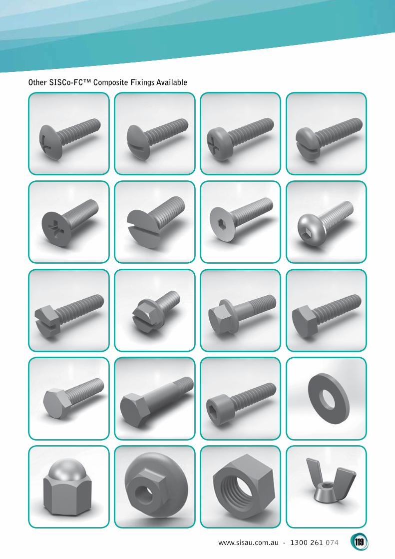
www.sisau.com.au - 1300 261 074 119
Other SISCo-FC™ Composite Fixings Available

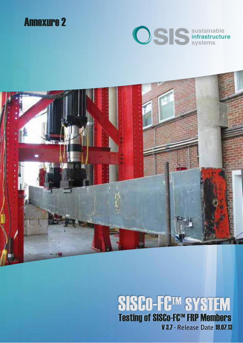
Testing of SISCo-FC™ FRP MembersV 3.7 - Release Date 19.07.13
Annexure 2
122
Testing of SISCo-FC™ FRP Members . . . . . . . . . . . . . . . . . . . . . . . . . . . . . . . . . . . . . . . . . . . . . . . . . . .4
254mm x 127mm x 12 .7mm I-BEAM . . . . . . . . . . . . . . . . . . . . . . . . . . . . . . . . . . . . . . . . . . . . . . . . . . . .7
609 .6mm x 9 .5mm x 190 .5mm x 19 .1mm I-BEAM . . . . . . . . . . . . . . . . . . . . . . . . . . . . . . . . . . . . . . . . . 8
609 .6mm x 9 .5mm x 190 .5mm x 19 .1mm I-BEAM - continued . . . . . . . . . . . . . . . . . . . . . . . . . . . . . . 9
Columns . . . . . . . . . . . . . . . . . . . . . . . . . . . . . . . . . . . . . . . . . . . . . . . . . . . . . . . . . . . . . . . . . . . . . . . . .10
Columns Tables . . . . . . . . . . . . . . . . . . . . . . . . . . . . . . . . . . . . . . . . . . . . . . . . . . . . . . . . . . . . . . . . . . .11
50 .8mm x 50 .8mm x 6 .4mm Angle . . . . . . . . . . . . . . . . . . . . . . . . . . . . . . . . . . . . . . . . . . . . . . . . . . .12
76 .2mm x 76 .2mm x 6 .4mm Angle . . . . . . . . . . . . . . . . . . . . . . . . . . . . . . . . . . . . . . . . . . . . . . . . . . .13
76 .2mm x 76 .2mm x 9 .5mm Angle . . . . . . . . . . . . . . . . . . . . . . . . . . . . . . . . . . . . . . . . . . . . . . . . . . .14
76 .2mm x 76 .2mm x 12 .7mm Angle . . . . . . . . . . . . . . . . . . . . . . . . . . . . . . . . . . . . . . . . . . . . . . . . . .15
101 .6mm x 101 .6mm x 6 .4mm Angle . . . . . . . . . . . . . . . . . . . . . . . . . . . . . . . . . . . . . . . . . . . . . . . . .16
101 .6mm x 101 .6mm x 9 .5mm Angle . . . . . . . . . . . . . . . . . . . . . . . . . . . . . . . . . . . . . . . . . . . . . . . . .17
101 .6mm x 101 .6mm x 12 .7mm Angle . . . . . . . . . . . . . . . . . . . . . . . . . . . . . . . . . . . . . . . . . . . . . . . .19
152 .4mm x 153 .4mm x 9 .5mm Angle . . . . . . . . . . . . . . . . . . . . . . . . . . . . . . . . . . . . . . . . . . . . . . . . .20
101 .6mm x 101 .6mm x 9 .5mm Square Tube . . . . . . . . . . . . . . . . . . . . . . . . . . . . . . . . . . . . . . . . . . . .21
152 .4mm x 153 .4mm x 9 .5mm Square Tube . . . . . . . . . . . . . . . . . . . . . . . . . . . . . . . . . . . . . . . . . . . .22
Corrosion Guide . . . . . . . . . . . . . . . . . . . . . . . . . . . . . . . . . . . . . . . . . . . . . . . . . . . . . . . . . . . . . . . . . .24
copyRight 2014 – Sustainable Infrastructure Systems (Aust) Pty Ltd
tRADE MARKS
SISCo-FC™, CoreSpan™ and StructuralComp™ are registered trademarks used under license
by Sustainable Infrastructure Systems (Aust) Pty Ltd . License permission granted by Sustainable
Infrastructure Systems (Aust) IP Pty Ltd
pAtENtS / pAtENtS pENDiNg
Parts of the SISCo-FC™ System are protected by either patents, or patents pending . Individual
components are protected by either patents, or patents pending . Fixing methodology is
protected by patents, or patents pending .
Contents

123
Weathering
Property loss is experienced in Fire Retardant (FR), Polyester, and Vinylester Fiberglass pultrusion when exposed
to continuous high temperatures. The loss of properties is considered during the designing stages. The following
table shows the percentage of propertreteon at certain continuous temperatures.
Testing of SISCo-FC™ FRP Members
temperature FR/polyester Vinylester
Ultimate Stress
37°C 85% 90%
51°C 70% 80%
65°C 50% 80%
79%C Not Recommended 75%
93°C Not Recommended 50%
temperature FR/polyester Vinylester
Modulus of Elasticity
37°C 100% 100%
51°C 90% 95%
65°C 85% 90%
79%C Not Recommended 88%
93°C Not Recommended 85%
After exposure to outdoor weathering, almost
all plastics undergo some degradation in surface
appearance.
The surface of pultrusions typically have good water
and ambient temperature resistance, but are attacked
by ultraviolet light.
Ultraviolet light is the light spectrum 290 to 400
nanometers. The light has higher energy and can
significantly degrade polymers by breaking chemical
bonds or starting chemical reactions that lead
to polymer degradation. Fire retardant polyester
formulations, which contain a halogen, are typically
more susceptible to ultraviolet light degradation, due
to the halogen additive. Ultraviolet light will cause
the surface of the pultrusion to fade (yellow) and lose
gloss. Over a longer period of time, fiberglass closest
to the surface will be exposed. This condition is known
as fiberbloom. Physical Properties are not affected by
this surface degradation.
SIS adds a UV stabilizer to our resin mix formulation.
This slows the affects of UV degradation. We also
incorporate a layer of polyester veil directly to the
surface of the pultrusion during processing. This
veil gives a resin rich surface and acts as a barrier
between the surface and the top layer of fiberglass
reinforcement. Pigments used in our resin formulations
also slow the effects of weathering.
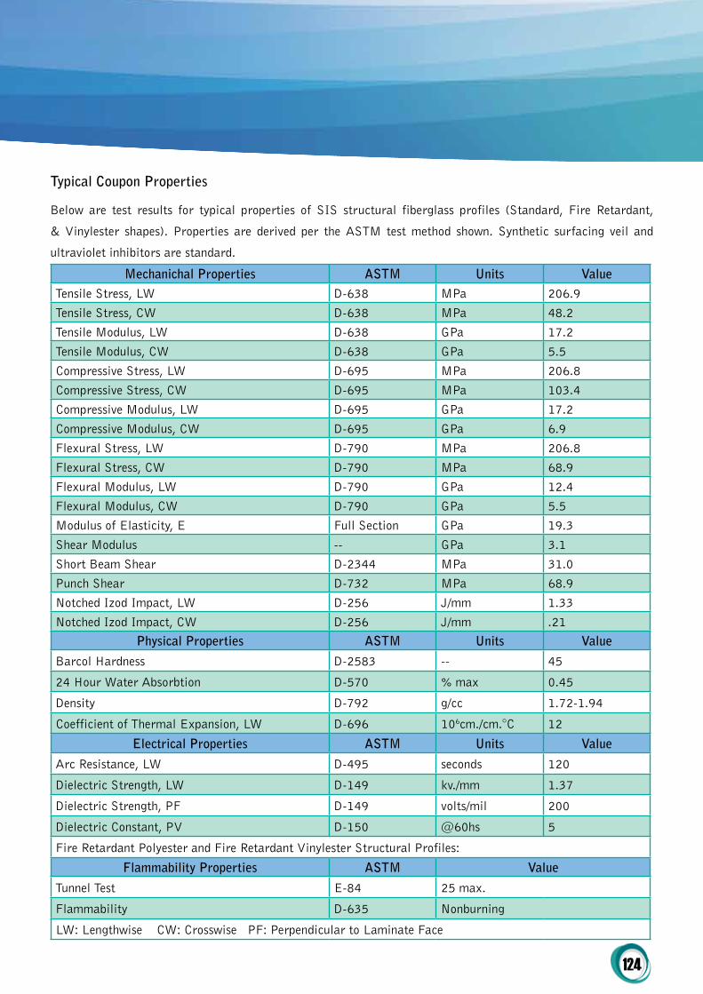
124
typical coupon properties
Below are test results for typical properties of SIS structural fiberglass profiles (Standard, Fire Retardant,
& Vinylester shapes). Properties are derived per the ASTM test method shown. Synthetic surfacing veil and
ultraviolet inhibitors are standard.
Mechanichal properties AStM Units ValueTensile Stress, LW D-638 MPa 206.9
Tensile Stress, CW D-638 MPa 48.2
Tensile Modulus, LW D-638 GPa 17.2
Tensile Modulus, CW D-638 GPa 5.5
Compressive Stress, LW D-695 MPa 206.8
Compressive Stress, CW D-695 MPa 103.4
Compressive Modulus, LW D-695 GPa 17.2
Compressive Modulus, CW D-695 GPa 6.9
Flexural Stress, LW D-790 MPa 206.8
Flexural Stress, CW D-790 MPa 68.9
Flexural Modulus, LW D-790 GPa 12.4
Flexural Modulus, CW D-790 GPa 5.5
Modulus of Elasticity, E Full Section GPa 19.3
Shear Modulus -- GPa 3.1
Short Beam Shear D-2344 MPa 31.0
Punch Shear D-732 MPa 68.9
Notched Izod Impact, LW D-256 J/mm 1.33
Notched Izod Impact, CW D-256 J/mm .21physical properties AStM Units Value
Barcol Hardness D-2583 -- 45
24 Hour Water Absorbtion D-570 % max 0.45
Density D-792 g/cc 1.72-1.94
Coefficient of Thermal Expansion, LW D-696 106cm./cm.°C 12
Electrical properties AStM Units Value
Arc Resistance, LW D-495 seconds 120
Dielectric Strength, LW D-149 kv./mm 1.37
Dielectric Strength, PF D-149 volts/mil 200
Dielectric Constant, PV D-150 @60hs 5
Fire Retardant Polyester and Fire Retardant Vinylester Structural Profiles:
Flammability properties AStM Value
Tunnel Test E-84 25 max.
Flammability D-635 Nonburning
LW: Lengthwise CW: Crosswise PF: Perpendicular to Laminate Face
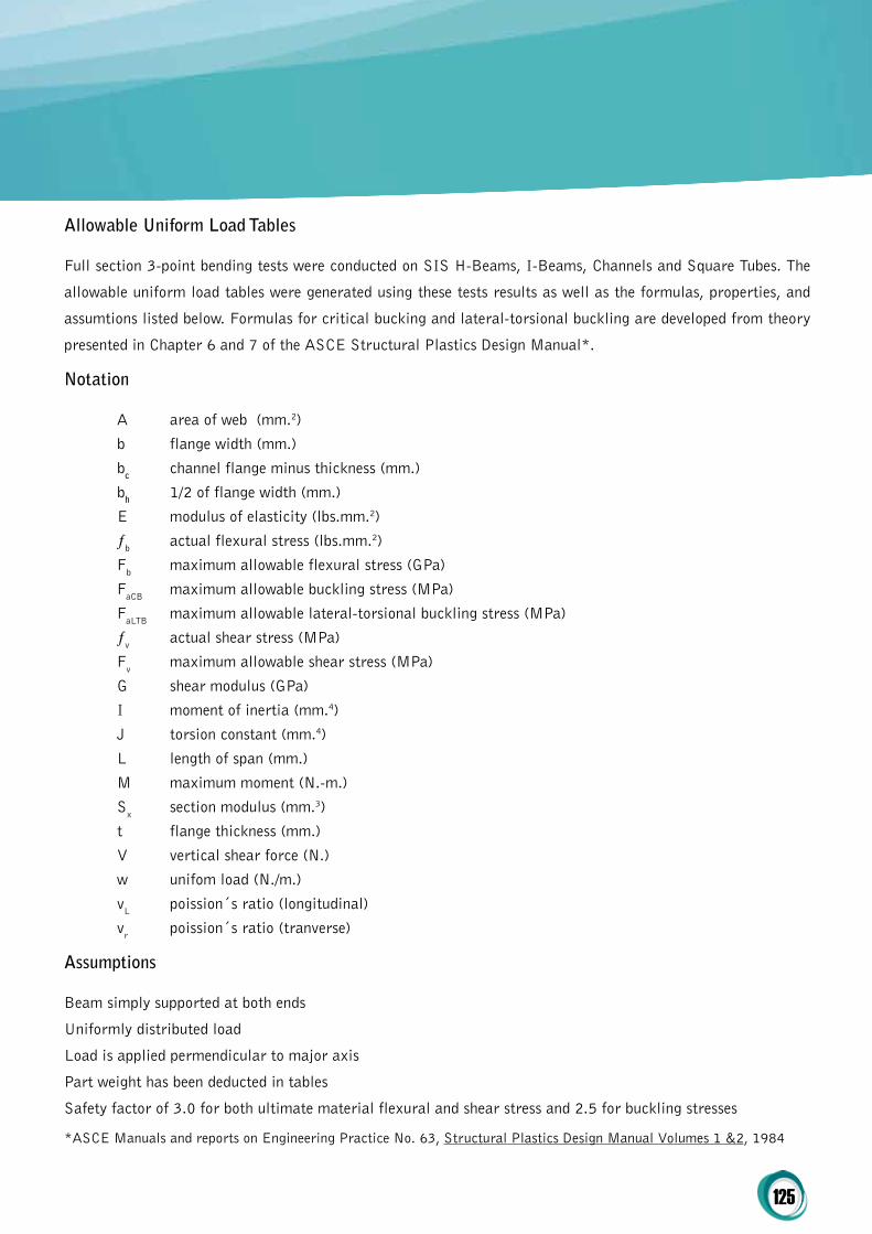
125
Allowable Uniform Load tables
Full section 3-point bending tests were conducted on SIS H-Beams, I-Beams, Channels and Square Tubes. The
allowable uniform load tables were generated using these tests results as well as the formulas, properties, and
assumtions listed below. Formulas for critical bucking and lateral-torsional buckling are developed from theory
presented in Chapter 6 and 7 of the ASCE Structural Plastics Design Manual*.
Notation
A area of web (mm.2)
b flange width (mm.)
bc channel flange minus thickness (mm.)
bh 1/2 of flange width (mm.)
E modulus of elasticity (lbs.mm.2)
ƒb actual flexural stress (lbs.mm.2)
Fb maximum allowable flexural stress (GPa)
FaCB maximum allowable buckling stress (MPa)
FaLTB maximum allowable lateral-torsional buckling stress (MPa)
ƒv actual shear stress (MPa)
Fv maximum allowable shear stress (MPa)
G shear modulus (GPa)
I moment of inertia (mm.4)
J torsion constant (mm.4)
L length of span (mm.)
M maximum moment (N.-m.)
Sx section modulus (mm.3)
t flange thickness (mm.)
V vertical shear force (N.)
w unifom load (N./m.)
vL poission´s ratio (longitudinal)
vr poission´s ratio (tranverse)
Assumptions
Beam simply supported at both ends
Uniformly distributed load
Load is applied permendicular to major axis
Part weight has been deducted in tables
Safety factor of 3.0 for both ultimate material flexural and shear stress and 2.5 for buckling stresses
*ASCE Manuals and reports on Engineering Practice No. 63, Structural Plastics Design Manual Volumes 1 &2, 1984

126
properties / Allowables Formulas
E = 19.3 GPa
G=3.1 GPa
Fb =68.9 MPa
Fv = 10.3 MPa
Allowable Critical Bucking Stress for laterally supported WF and I Beams
FaCB = π
2 .935
Et3 vTEt3 - (.656)
vTEt2 +
(2.082)
Gt3 /2.5 bh
2t 12λ 12λ 12λ 12
λ=(1-vLvT)
Allowable Lateral-Torsional Buckling Stress for laterally unsupported I Beams
FaLTB= Cπ EIyGJ +
d2 π2 E2-Iy2
/2.5 S(KL) (4)(KL)2
C= 1.13 and K= 1.0 for uniform load simple beam*
Allowable Critical Buckling Stress for Channels laterally supported to eliminated warping and twist
FaCB = G(t/bc)2/2.5
Allowable Bending Stress for Square Tube (b/t<=16)
Fb = 68.94 Mpa.
*ASCE Manuals and reports on Engineering Practice No. 63, Structural Plastics Design Manual Volumes 1 &2, 1984
∆ = 5wL4 + wL2
384EI 8AwG
ƒh = M
Sx
ƒh = V
Aw
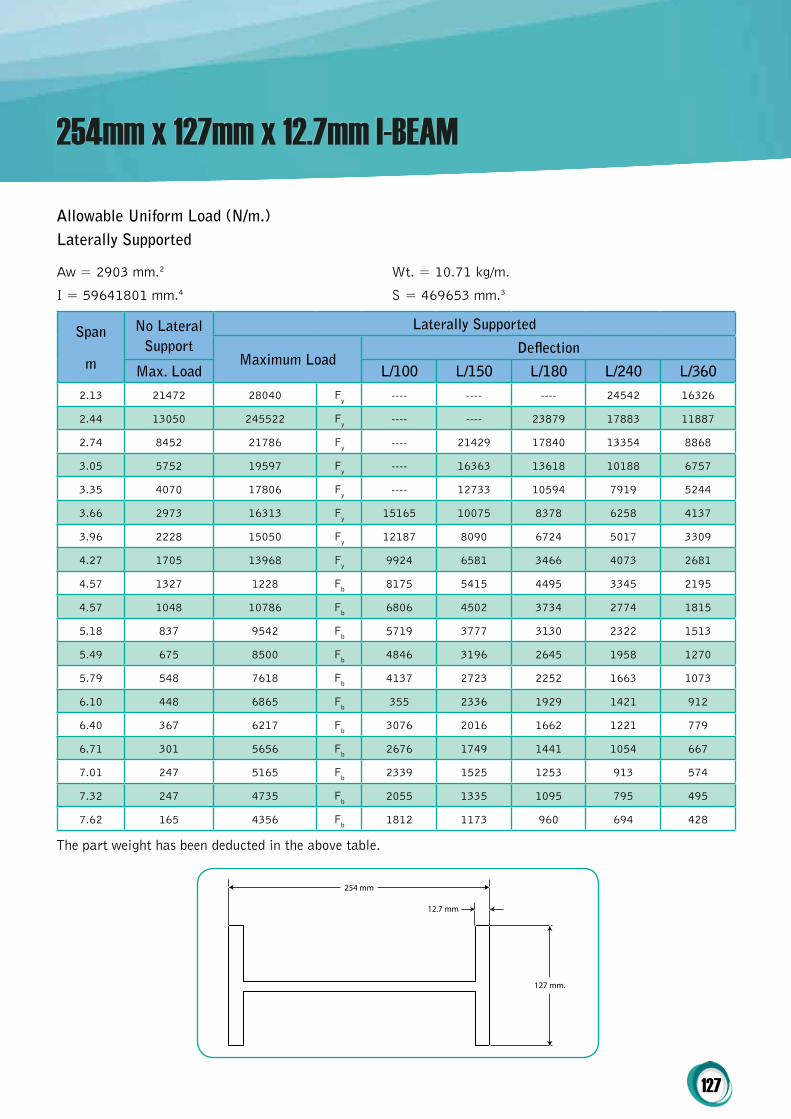
127
254mm x 127mm x 12.7mm I-BEAM
254 mm
127 mm.
12.7 mm
Span
m
No Lateral Support
Laterally Supported
Maximum LoadDeflection
Max. Load L/100 L/150 L/180 L/240 L/360
2.13 21472 28040 Fy ---- ---- ---- 24542 16326
2.44 13050 245522 Fy ---- ---- 23879 17883 11887
2.74 8452 21786 Fy ---- 21429 17840 13354 8868
3.05 5752 19597 Fy ---- 16363 13618 10188 6757
3.35 4070 17806 Fy ---- 12733 10594 7919 5244
3.66 2973 16313 Fy 15165 10075 8378 6258 4137
3.96 2228 15050 Fy 12187 8090 6724 5017 3309
4.27 1705 13968 Fy 9924 6581 3466 4073 2681
4.57 1327 1228 Fb 8175 5415 4495 3345 2195
4.57 1048 10786 Fb 6806 4502 3734 2774 1815
5.18 837 9542 Fb 5719 3777 3130 2322 1513
5.49 675 8500 Fb 4846 3196 2645 1958 1270
5.79 548 7618 Fb 4137 2723 2252 1663 1073
6.10 448 6865 Fb 355 2336 1929 1421 912
6.40 367 6217 Fb 3076 2016 1662 1221 779
6.71 301 5656 Fb 2676 1749 1441 1054 667
7.01 247 5165 Fb 2339 1525 1253 913 574
7.32 247 4735 Fb 2055 1335 1095 795 495
7.62 165 4356 Fb 1812 1173 960 694 428
The part weight has been deducted in the above table.
Allowable Uniform Load (N/m.)Laterally Supported
Aw = 2903 mm.2 Wt. = 10.71 kg/m.
I = 59641801 mm.4 S = 469653 mm.3

128
609.6mm x 9.5mm x 190.5mm x 19.1mm I-BEAM
609.6 mm.
190.5 mm.
9.5 mm.
19.1 mm.
The part weight has been deducted in the above table.
Span
m
No Lateral Support
Laterally Supported
Maximum LoadDeflection
Max. Load L/100 L/150 L/180 L/240 L/360
3.05 36730 36730 Fy ---- ---- ---- ---- 35335
3.35 33371 33371 Fy ---- ---- ---- ---- 29887
3.66 24071 30571 Fy ---- ---- ---- ---- 25450
3.96 17569 28203 Fy ---- ---- ---- ---- 21804
4.27 13127 26172 Fy ---- ---- ---- ---- 18782
4.57 10006 24413 Fy ---- ---- ---- ---- 16262
4.88 7760 22873 Fy ---- ---- ---- 21330 14146
5.18 6108 21514 Fy ---- ---- ---- 18651 12360
5.49 4870 20307 Fy ---- ---- ---- 16378 10844
5.79 3926 19226 Fy ---- ---- ---- 14439 9552
6.10 3196 18254 Fy ---- ---- 17111 12778 8445
6.40 2624 17374 Fy ---- ---- 15205 11348 7492
6.71 2170 16574 Fy ---- 16314 13558 10113 6668
7.01 1806 15844 Fy ---- 14598 12128 9041 5953
7.32 1511 15174 Fy ---- 13104 10883 8107 5331
Allowable Uniform Load (N/m.)Laterally Supported
Aw = 5445 mm.2 Wt. = 22.62 kg/m.
I = 78126686 mm.4 S = 2563265 mm.3

129
Span
m
No Lateral Support
Laterally Supported
Maximum LoadDeflection
Max. Load L/100 L/150 L/180 L/240 L/360
7.62 1269 14559 Fy ---- 1179 9794 7290 4786
7.92 106 13990 Fy ---- 10651 8839 6574 4309
83.23 903 13464 Fy ---- 9641 7997 5943 3888
8.53 764 12975 Fy ---- 8749 7254 5385 3516
8.84 647 12520 Fy 12049 7959 6596 4891 3187
9.14 547 12095 Fy 10996 7256 6010 4452 2894
9.45 462 11698 Fy 10056 6630 5488 4061 2633
9.75 389 11326 Fy 9216 6070 5022 3711 2400
10.06 325 10976 Fy 8463 5568 4603 3397 2191
10.36 271 10646 Fy 7787 5117 4227 3115 2003
10.67 223 10336 Fy 7177 4711 3889 2861 1834
10.97 181 10043 Fy 6627 4344 3583 2632 1681
11.28 144 9765 Fy 6129 4012 3306 2424 1542
11.58 112 9502 Fy 567 3711 3055 2236 1417
11.89 83 9253 Fy 5267 3437 2827 2065 1303
12.19 58 9016 Fy 4893 3188 2620 1909 1199
The part weight has been deducted in the above table.
Allowable Uniform Load (N/m.)Laterally Supported
Aw = 5445mm.2 Wt. = 22.62kg/m.
I = 781266386mm.4 S = 2563265mm.3
609.6mm x 9.5mm x 190.5mm x 19.1mm I-BEAM - continued
609.6 mm.
190.5 mm.
9.5 mm.
19.1 mm.

130
Columns
Ultimate stress vs. slenderness ratio curves were developed from the testing. The curves developed are based on
the Euler Buckling Stress Equation and a straight line transition from Euler Buckling to ultimate
stress. The allowable concentric axial load tables were generated from these curves.
The tables are based on a safety factor of three.
Full section column testing

131
Columns Tables
Allowable concentric Axial Stresses and Loads
Notation
A area (mm.2)
b width of flange/leg/wall (mm.)
t thickness of flange (mm.)
r minimum radius gyration (mm.)
l length (mm.)
K effective column length factor
Fa allowable column concentric axial stress (Mpa)
Pa allowable column centric axial load (N.)
AngleMaximum allowable stress:
b/t = 6 41.3Mpa
b/t = 8 33.5Mpa
b/t = 10.7 24.1Mpa
b/t = 12 19.5Mpa
b/t = 16 12.6Mpa
Square tube (1/4" wall)Maximum allowable stress:
b/t ≤ 16 68.9Mpa
WF- & i-Beam Maximum allowable stress:
b/t ≤ 12 68.9Mpa
b/t = 13.3 68.9Mpa
b/t = 16 50.5Mpa
b/t = 20 32.3Mpa
b/t = 21.3 28.4Mpa
b/t = 24 22.4Mpa
b/t = 26.7 18.1Mpa

132
50.8mm x 50.8mm x 6.4mm Angle
Allowable concentric Axial Stresses and Loads
A = 593.5mm.2
r = 9.65mm.
b/t = 8
Effective Length (m.) Kl r Fa (kpa) pa (N)
0.30 31.6 24207 14368
0.46 47.4 19550 11604
0.61 63.2 14892 8839
0.76 78.9 10234 6075
0.91 94.7 7077 4200
1.07 110.5 5199 3086
1.22 126.3 3981 2363
1.37 142.1 3145 1867
1.52 157.9 2548 1512
1.68 173.7 2105 1250
1.83 189.5 1769 1050

133
76.2mm x 76.2mm x 6.4mm Angle
Allowable concentric Axial Stresses and Loads
A = 916mm.2
r = 14.99mm.
b/t = 12
Effective Length (m.) Kl r Fa (kpa) pa (N)
0.30 20.3 16852 15438
0.46 30.5 15511 14210
0.61 40.7 14171 12982
0.76 50.8 12830 11754
0.91 61.0 11490 10526
1.07 71.2 10149 9298
1.22 81.4 8809 8070
1.37 91.5 7468 6842
1.52 101.7 6141 5626
1.68 111.9 5075 4650
1.83 122.0 4265 3907
1.98 132.2 3634 3329
2.13 142.4 3133 2871
2.29 152.5 2729 2501
2.44 162.7 2399 2198
2.59 172.9 2125 1947
2.74 183.1 1895 1736
2.90 193.2 1701 1559
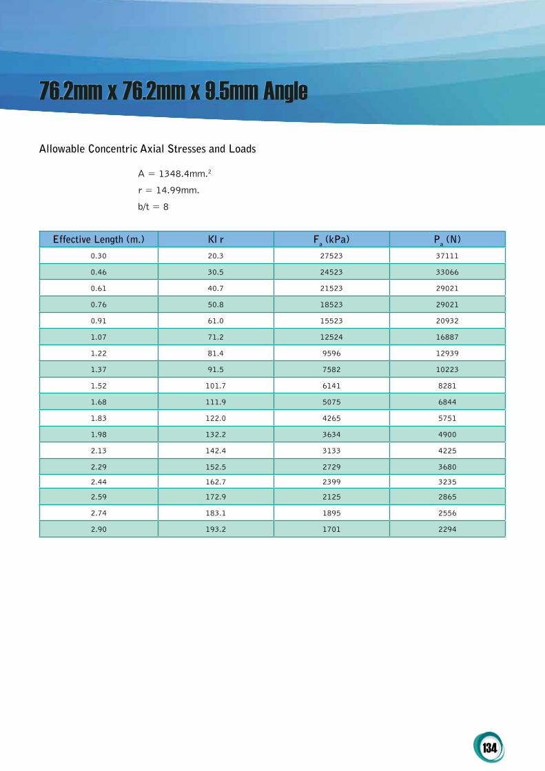
134
76.2mm x 76.2mm x 9.5mm Angle
Allowable concentric Axial Stresses and Loads
A = 1348.4mm.2
r = 14.99mm.
b/t = 8
Effective Length (m.) Kl r Fa (kpa) pa (N)
0.30 20.3 27523 37111
0.46 30.5 24523 33066
0.61 40.7 21523 29021
0.76 50.8 18523 29021
0.91 61.0 15523 20932
1.07 71.2 12524 16887
1.22 81.4 9596 12939
1.37 91.5 7582 10223
1.52 101.7 6141 8281
1.68 111.9 5075 6844
1.83 122.0 4265 5751
1.98 132.2 3634 4900
2.13 142.4 3133 4225
2.29 152.5 2729 3680
2.44 162.7 2399 3235
2.59 172.9 2125 2865
2.74 183.1 1895 2556
2.90 193.2 1701 2294

135
76.2mm x 76.2mm x 12.7mm Angle
Allowable concentric Axial Stresses and Loads
A = 1741.9mm.2
r = 14.99mm.
b/t = 6
Effective Length (m.) Kl r Fa (kpa) pa (N)
0.30 20.3 33326 58051
0.46 30.5 29304 51046
0.61 40.7 25283 44041
0.76 50.8 21262 37036
0.91 61.0 17059 29716
1.07 71.2 12533 21832
1.22 81.4 9596 16715
1.37 91.5 7582 13207
1.52 101.7 6141 10698
1.68 111.9 5075 8841
1.83 122.0 4265 7429
1.98 132.2 3634 6330
2.13 142.4 3133 5458
2.29 152.5 2729 4755
2.44 162.7 2399 4179
2.59 172.9 2125 3702
2.74 183.1 1895 3302
2.90 193.2 1701 2963

136
Allowable concentric Axial Stresses and Loads
A = 1225.8mm.2
r = 20.32mm.
b/t = 16
Effective Length (m.) Kl r Fa (kpa) pa (N)
0.30 15.0 11610 14381
0.46 22.5 11095 13744
0.61 30.0 10581 13107
0.76 37.5 10067 12470
0.91 45.0 9553 11833
1.07 52.5 9039 11196
1.22 60.0 8524 10559
1.37 67.5 8010 9922
1.52 75.0 7496 9285
1.68 82.5 6982 8648
1.83 90.0 6467 8011
1.98 97.5 5953 7374
2.13 105.0 5439 6737
2.29 112.5 4925 6100
2.44 120.0 4411 5463
2.59 127.5 3907 4840
2.74 135.0 3485 4317
2.90 142.5 3128 3874
3.05 150.0 2823 3497

137
101.6mm x 101.6mm x 9.5mm Angle
Allowable concentric Axial Stresses and Loads
A = 1832.3mm.2
r = 20.07mm.
b/t = 10.7
Effective Length (m.) Kl r Fa (kpa) pa (N)
0.30 15.2 21388 39188
0.46 22.8 20013 36668
0.61 30.4 18637 34148
0.76 38.0 17262 31628
0.91 45.6 15887 29108
1.07 53.2 14511 26588
1.22 60.8 13136 24068
1.37 68.4 11761 21549
1.52 75.9 10385 19029
1.68 83.5 9010 16509
1.83 91.1 7646 14010
1.98 98.7 6515 11937
2.13 106.3 5618 10293
2.29 113.9 4894 8966
2.44 121.5 4301 7881
2.59 129.1 3810 6981
2.74 136.7 3398 6227
2.90 144.3 3050 5588
3.05 151.9 2753 5044
3.20 159.5 2497 4575
3.35 167.1 2275 4168
3.51 174.7 2081 3814
3.66 182.3 1912 3502
3.81 189.9 1762 3228

138
101.6mm x 101.6mm x 12.7mm Angle
Allowable concentric Axial Stresses and Loads
A = 2387.1mm.2
r = 19.81mm.
b/t = 8
Effective Length (m.) Kl r Fa (kpa) pa (N)
0.30 15.4 28984 69188
0.46 23.1 26715 63771
0.61 30.8 24446 58355
0.76 38.5 22177 52938
0.91 46.1 19908 47522
1.07 53.8 17639 42105
1.22 61.5 15370 36689
1.37 69.2 13101 31272
1.52 76.9 10831 25856
1.68 84.6 8871 21175
1.83 92.3 7454 17793
1.98 100.0 6351 15161
2.13 107.7 5476 13072
2.29 115.4 4770 11388
2.44 123.1 4193 10009
2.59 130.8 3714 8866
2.74 138.5 3313 7908
2.90 146.2 2973 7098
3.05 153.8 2683 6406
3.20 161.5 2434 5810
3.35 169.2 2218 5294
3.51 176.9 2029 4843
3.66 184.6 1863 4448
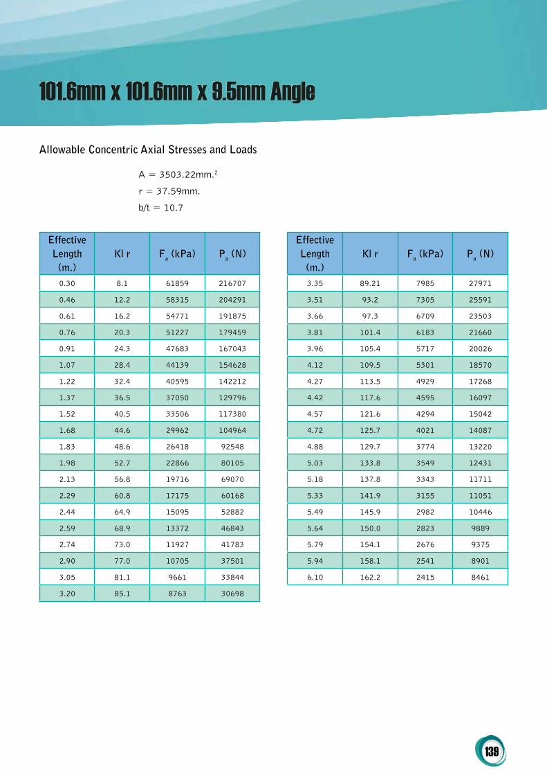
139
101.6mm x 101.6mm x 9.5mm Angle
Allowable concentric Axial Stresses and Loads
A = 3503.22mm.2
r = 37.59mm.
b/t = 10.7
Effective Length
(m.)Kl r Fa (kpa) pa (N)
0.30 8.1 61859 216707
0.46 12.2 58315 204291
0.61 16.2 54771 191875
0.76 20.3 51227 179459
0.91 24.3 47683 167043
1.07 28.4 44139 154628
1.22 32.4 40595 142212
1.37 36.5 37050 129796
1.52 40.5 33506 117380
1.68 44.6 29962 104964
1.83 48.6 26418 92548
1.98 52.7 22866 80105
2.13 56.8 19716 69070
2.29 60.8 17175 60168
2.44 64.9 15095 52882
2.59 68.9 13372 46843
2.74 73.0 11927 41783
2.90 77.0 10705 37501
3.05 81.1 9661 33844
3.20 85.1 8763 30698
Effective Length
(m.)Kl r Fa (kpa) pa (N)
3.35 89.21 7985 27971
3.51 93.2 7305 25591
3.66 97.3 6709 23503
3.81 101.4 6183 21660
3.96 105.4 5717 20026
4.12 109.5 5301 18570
4.27 113.5 4929 17268
4.42 117.6 4595 16097
4.57 121.6 4294 15042
4.72 125.7 4021 14087
4.88 129.7 3774 13220
5.03 133.8 3549 12431
5.18 137.8 3343 11711
5.33 141.9 3155 11051
5.49 145.9 2982 10446
5.64 150.0 2823 9889
5.79 154.1 2676 9375
5.94 158.1 2541 8901
6.10 162.2 2415 8461

140
152.4mm x 153.4mm x 9.5mm Angle
Allowable concentric Axial Stresses and Loads
A = 5335.47mm.2
r = 58.17mm.
b/t = 16
Effective Length
(m.)Kl r Fa (kpa) pa (N)
0.30 5.2 51967 277266
0.46 7.9 50371 268753
0.61 10.5 48775 260239
0.76 13.1 47179 251725
0.91 15.7 45584 243211
1.07 18.3 43988 234697
1.22 21.0 42392 226183
1.37 23.6 40797 217669
1.52 26.2 39201 209155
1.68 28.8 37605 200641
1.83 31.4 36009 192127
1.98 34.1 34414 183613
2.13 36.7 32818 175099
2.29 39.3 31222 166585
2.44 41.9 29626 158071
2.59 44.5 28031 149557
2.74 47.2 26435 141043
2.90 49.8 24839 132529
3.05 52.4 23129 123407
3.20 55.0 20979 111934
Effective Length
(m.)Kl r Fa (kpa) pa (N)
3.35 57.6 19115 10198
3.51 60.3 17489 9331
3.66 62.9 16962 8569
3.81 65.5 14803 7898
3.96 68.1 13686 7302
4.12 70.7 12691 6771
4.27 73.4 11801 6296
4.42 76.0 11001 5869
4.57 78.6 10280 5484
4.72 81.2 9627 5136
4.88 83.8 9035 4820
5.03 86.5 8496 4532
5.18 89.1 8003 42701
5.33 91.7 7552 40290
5.49 94.3 6758 38089
5.64 96.9 6758 36057
5.79 99.6 6407 34185
5.94 102.2 6083 32454
6.10 104.8 5782 30852

141
101.6mm x 101.6mm x 9.5mm Square Tube
Allowable concentric Axial Stresses and Loads
A = 3503.22mm.2
r = 37.59mm.
b/t = 10.7
Effective Length
(m.)Kl r Fa (kpa) pa (N)
0.30 8.1 61859 216707
0.46 12.2 58315 204291
0.61 16.2 54771 191875
0.76 20.3 51227 179459
0.91 24.3 47683 167043
1.07 28.4 44139 154628
1.22 32.4 40595 226183
1.37 36.5 37050 29796
1.52 40.5 33506 117380
1.68 44.6 29962 104964
1.83 48.6 26418 92548
1.98 52.7 22866 80105
2.13 56.8 19716 69070
2.29 60.8 17175 60168
2.44 64.9 15095 52882
2.59 68.9 13372 46843
2.74 73.0 11927 41783
2.90 77.0 10705 37501
3.05 81.1 9661 33844
3.20 85.1 8763 30698
Effective Length
(m.)Kl r Fa (kpa) pa (N)
3.35 89.2 785 27971
3.51 93.2 7305 2591
3.66 97.3 6709 23503
3.81 101.4 6183 21660
3.96 105.4 5717 20026
4.12 109.5 5301 18570
4.27 113.5 4929 17268
4.42 117.6 4595 16097
4.57 121.6 4294 15042
4.72 125.7 4021 14087
4.88 129.7 3773 13220
5.03 133.8 3549 12431
5.18 137.8 3343 11711
5.33 141.9 3155 11051
5.49 145.9 2982 10446
5.64 150.0 2823 9889
5.79 1541 2676 9372
5.94 158.1 2541 8901
6.10 162.2 2415 8461

142
152.4mm x 153.4mm x 9.5mm Square Tube
Allowable concentric Axial Stresses and Loads
A = 5335.47mm.2
r = 58.17mm.
b/t = 16
Effective Length
(m.)Kl r Fa (kpa) pa (N)
0.30 5.2 51967 277266
0.46 7.9 50371 268753
0.61 10.5 48775 260239
0.76 13.1 47179 251725
0.91 15.7 45584 243211
1.07 18.3 43988 234697
1.22 21.0 42392 226183
1.37 23.6 40797 217669
1.52 26.2 39201 209155
1.68 28.8 37605 200641
1.83 31.4 36009 192127
1.98 34.1 34414 183613
2.13 36.7 32818 175099
2.29 39.3 31222 166585
2.44 41.9 29626 158071
2.59 44.5 28031 149557
2.74 47.2 26435 141043
2.90 49.8 24839 132529
3.05 52.4 23129 123407
3.20 55.0 20979 111934
Effective Length
(m.)Kl r Fa (kpa) pa (N)
3.35 57.6 19115 10198
3.51 60.3 17489 9331
3.66 62.9 16962 8569
3.81 65.5 14803 7898
3.96 68.1 13686 7302
4.12 70.7 12691 6771
4.27 73.4 11801 6296
4.42 76.0 11001 5869
4.57 78.6 10280 5484
4.72 81.2 9627 5136
4.88 83.8 9035 4820
5.03 86.5 8496 4532
5.18 89.1 8003 42701
5.33 91.7 7552 40290
5.49 94.3 6758 38089
5.64 96.9 6758 36057
5.79 99.6 6407 34185
5.94 102.2 6083 32454
6.10 104.8 5782 30852
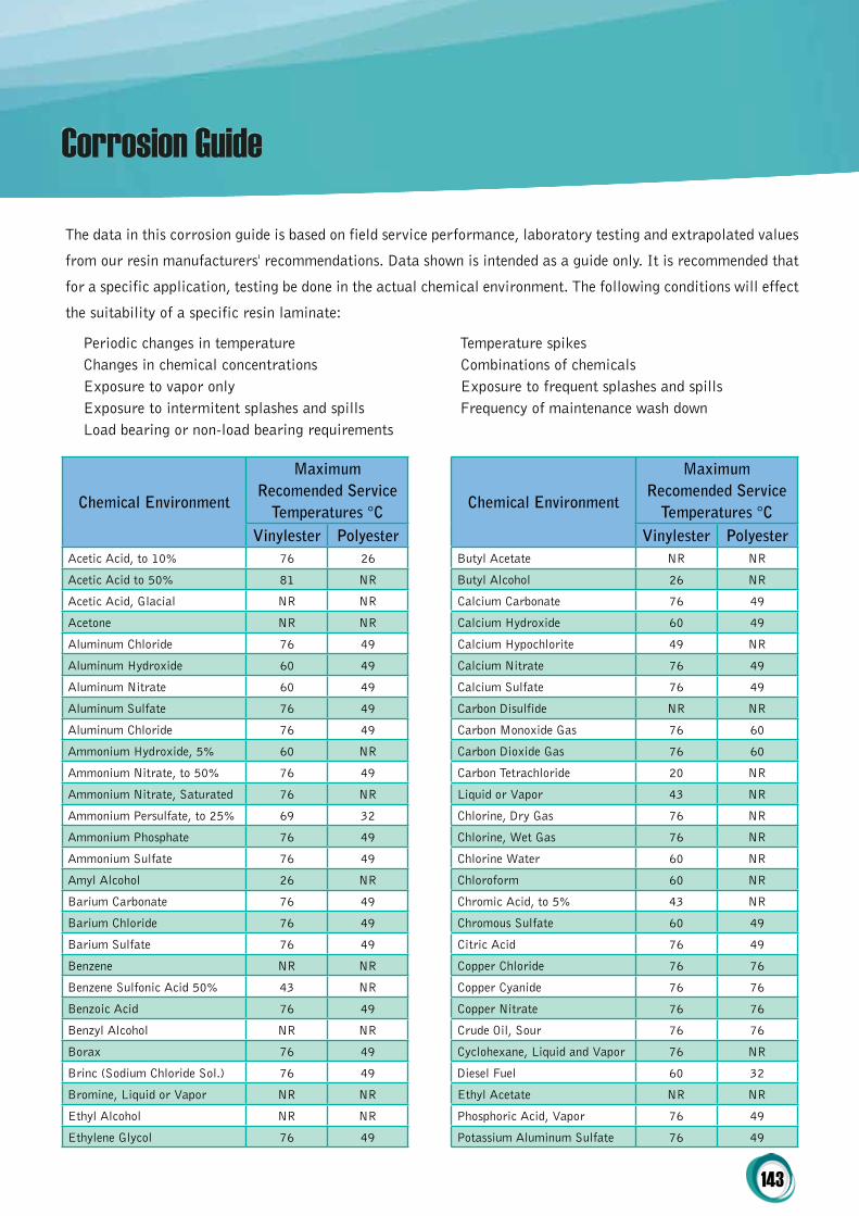
143
The data in this corrosion guide is based on field service performance, laboratory testing and extrapolated values
from our resin manufacturers' recommendations. Data shown is intended as a guide only. It is recommended that
for a specific application, testing be done in the actual chemical environment. The following conditions will effect
the suitability of a specific resin laminate:
Corrosion Guide
chemical Environment
Maximum Recomended Service
temperatures °cVinylester polyester
Acetic Acid, to 10% 76 26
Acetic Acid to 50% 81 NR
Acetic Acid, Glacial NR NR
Acetone NR NR
Aluminum Chloride 76 49
Aluminum Hydroxide 60 49
Aluminum Nitrate 60 49
Aluminum Sulfate 76 49
Aluminum Chloride 76 49
Ammonium Hydroxide, 5% 60 NR
Ammonium Nitrate, to 50% 76 49
Ammonium Nitrate, Saturated 76 NR
Ammonium Persulfate, to 25% 69 32
Ammonium Phosphate 76 49
Ammonium Sulfate 76 49
Amyl Alcohol 26 NR
Barium Carbonate 76 49
Barium Chloride 76 49
Barium Sulfate 76 49
Benzene NR NR
Benzene Sulfonic Acid 50% 43 NR
Benzoic Acid 76 49
Benzyl Alcohol NR NR
Borax 76 49
Brinc (Sodium Chloride Sol.) 76 49
Bromine, Liquid or Vapor NR NR
Ethyl Alcohol NR NR
Ethylene Glycol 76 49
Periodic changes in temperatureChanges in chemical concentrationsExposure to vapor onlyExposure to intermitent splashes and spillsLoad bearing or non-load bearing requirements
Temperature spikesCombinations of chemicalsExposure to frequent splashes and spillsFrequency of maintenance wash down
chemical Environment
Maximum Recomended Service
temperatures °cVinylester polyester
Butyl Acetate NR NR
Butyl Alcohol 26 NR
Calcium Carbonate 76 49
Calcium Hydroxide 60 49
Calcium Hypochlorite 49 NR
Calcium Nitrate 76 49
Calcium Sulfate 76 49
Carbon Disulfide NR NR
Carbon Monoxide Gas 76 60
Carbon Dioxide Gas 76 60
Carbon Tetrachloride 20 NR
Liquid or Vapor 43 NR
Chlorine, Dry Gas 76 NR
Chlorine, Wet Gas 76 NR
Chlorine Water 60 NR
Chloroform 60 NR
Chromic Acid, to 5% 43 NR
Chromous Sulfate 60 49
Citric Acid 76 49
Copper Chloride 76 76
Copper Cyanide 76 76
Copper Nitrate 76 76
Crude Oil, Sour 76 76
Cyclohexane, Liquid and Vapor 76 NR
Diesel Fuel 60 32
Ethyl Acetate NR NR
Phosphoric Acid, Vapor 76 49
Potassium Aluminum Sulfate 76 49
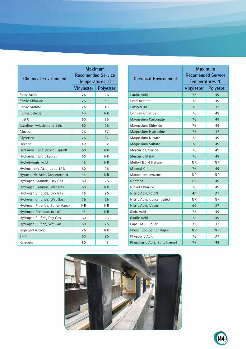
144
chemical Environment
Maximum Recomended Service
temperatures °cVinylester polyester
Fatty Acids 76 26
Ferric Chloride 76 43
Ferric Sulfate 76 43
Formaldehyde 43 NR
Fuel Oil 60 26
Gasoline, Aviation and Ethyl 60 26
Glucose 76 37
Glycerine 76 37
Hexane 49 32
Hydraulic Fluid (Glycol Based) 60 NR
Hydraulic Fluid Skydraul 60 NR
Hydrobromic Acid 43 NR
Hydrochloric Acid, up to 15% 60 26
Hyrochloric Acid, Concentrated 43 NR
Hydrogen Bromide, Dry Gas 60 26
Hydrogen Bromine, Wet Gas 60 NR
Hydrogen Chloride, Dry Gas 76 26
Hydrogen Chloride, Wet Gas 76 26
Hydrogen Fluoride, Sol or Vapor NR NR
Hydrogen Peroxide, to 10% 43 NR
Hydrogen Sulfide, Dry Gas 60 26
Hydrogen Sulfide, Wet Gas 60 26
Isopropyl Alcohol 26 NR
JP-4 60 26
Kerosene 60 43
chemical Environment
Maximum Recomended Service
temperatures °cVinylester polyester
Lactic Acid 76 49
Lead Acetate 76 49
Linseed Oil 76 37
Lithium Chloride 76 49
Magnesium Carbonate 76 49
Magnesium Chloride 76 49
Magnesium Hydroxide 76 37
Magnesium Nitrate 76 49
Magnesium Sulfate 76 49
Mercuric Chloride 76 49
Mercuric Metal 76 49
Methyl Ethyl Ketone NR NR
Mineral Oil 76 49
Monochlorobenzene NR NR
Naphtha 60 49
Nickel Chloride 76 49
Nitric Acid, to 5% 43 37
Nitric Acid, Concentrated NR NR
Nitric Acid, Vapor 60 37
Oleic Acid 76 49
Oxalic Acid 76 49
Paper Mill Liquor 37 37
Phenol Solution or Vapor NR NR
Phosporic Acid 76 37
Phosphoric Acid, Salts thereof 76 49
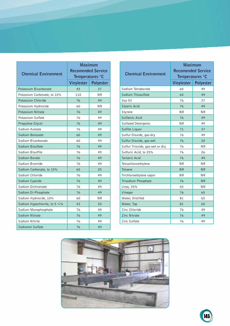
145
chemical Environment
Maximum Recomended Service
temperatures °cVinylester polyester
Sodium Tetraborate 60 49
Sodium Thiosulfate 60 49
Soy Oil 76 37
Stearic Acid 76 49
Styrene NR NR
Sulfamic Acid 76 49
Sulfated Detergents NR 49
Sulfite Liquor 71 37
Sulfur Dioxide, gas-dry 76 49
Sulfur Dioxide, gas-wet 76 20
Sulfur Trioxide, gas-wet or dry 76 NR
Sulfuric Acid, to 25% 76 26
Tartaric Acid 76 49
Tetrachloroethylene NR NR
Toluene NR NR
Trichloroethylene vapor NR NR
Trisodium Phosphate 76 NR
Urea, 35% 43 NR
Vinegar 76 65
Water, Distilled 81 65
Water, Tap 81 65
Zinc Chloride 76 49
Zinc Nitrate 76 49
Zinc Sulfate 76 49
chemical Environment
Maximum Recomended Service
temperatures °cVinylester polyester
Potassium Bicarbonate 43 37
Potassium Carbonate, to 10% 110 NR
Potassium Chloride 76 49
Potassium Hydroxide 60 NR
Potassium Nitrate 76 49
Potassium Sulfate 76 49
Propylene Glycol 76 49
Sodium Acetate 76 49
Sodium Benzoate 60 49
Sodium Bicarbonate 60 49
Sodium Bisulfate 76 49
Sodium Bisulfite 76 49
Sodium Borate 76 49
Sodium Bromide 76 49
Sodium Carbonate, to 10% 60 20
Sodium Chloride 76 49
Sodium Cyanide 76 49
Sodium Dichromate 76 49
Sodium Di-Phosphate 76 49
Sodium Hydroxide, 10% 60 NR
Sodium Hypochlorite, to 5 ¼% 43 20
Sodium Monophosphate 76 49
Sodium Nitrate 76 49
Sodium Nitrite 76 49
Sodiumm Sulfate 76 49


Terms & Conditions of Tradev2.4
Annexure 3
148
Sustainable Infrastructure Systems (Aust) Pty Ltd
(‘SIS’)
ABN: 61 160 899 703
These are the entire terms and conditions of trade
for goods supplied by SIS on or after 1st July, 2013
to customers within Australia or export customers
outside Australia (the ‘Customer’).
1. Definitions
Under these terms, unless the context otherwise
requires:
a. ‘SIS’ means Sustainable Infrastructure Systems
(Aust) Pty Ltd;
b. ‘Customer’ means the Customer as specified in
the Account Application and any Quotations
provided to prospective Customers;
c. ‘Quotation’ means SIS’s quotation for the supply
of the Goods to an existing or prospective
customer;
d. ‘Goods’ means the goods sold and purchased or
agreed to be sold and purchased, pursuant to
the Quotation;
e. ‘Order’ means the Customer’s instructions to
SIS to supply the Goods, pursuant to Quotation;
f. ‘Default Event’ means any of the following:
i. The customer does not make a payment
due to SIS;
ii. The customer is unable to pay its debts as
and when they fall due (insolvent);
iii. The customer ceases or suspends to conduct
its business, or threatens to do the same;
iv. A resolution passed or proposed or an
order made or a summon is presented to
wind up the customer;
v. A receiver and / or manager or other form
of insolvency administrator is appointed
over all or part of the customer’s assets;
vi. The customer makes or proposes to make
any arrangement with its creditors;
vii. The customer commits an act of bankruptcy;
viii. Execution is levied on any of the customers’
assets.
2. Applications
a. All orders placed with SIS shall only be accepted
subject to these Terms and Conditions of Trade.
SIS may at any time, and from time to time,
alter these Terms and Conditions and such
altered Terms and Conditions of Trade shall
apply after notification by SIS to the Customer.
3. Payment, Credit and Prices
a. The Customer shall pay for the Goods in
Australian currency, unless quoted otherwise,
at the price specified in the Quotation;
b. The Customer must pay for all the Goods before
the due date stated on the invoices issued by
SIS;
c. The Customer shall pay on delivery the full
amount of the purchase for three consecutive
orders prior to a credit application being
considered / approved;
d. Amount of the Goods in excess of the Approved
Credit Limit must be payable prior to delivery;
e. Interest is charged on amounts outstanding
after 21 days from due date;
f. SIS may withdraw any credit or limit the amount
of credit extended to the Customer at any time;
g. The Customer must pay the GST and any other
applicable taxes on the Goods;
Terms & Conditions of Trade

149
h. All prices shall be those referred to in SIS’s
price lists and/or arrangements current at the
date of invoice and prices shall be subject to
change without notice;
i. If the total weight or length of any item supplied
includes a fraction of a kilogram or metre, the
Customer will be invoiced and must pay for the
fraction as a whole kilogram or metre;
j. If a default event occurs:
i. SIS may withhold further deliveries of Goods
and/or withdraw any credit facilities; and;
ii. All amounts outstanding to SIS by the Customer,
even if not otherwise due for payment, become
immediately payable.
4. Deliveries
a. SIS will deliver the Goods to the delivery address
as specified by the Customer in the order;
b. The Customer shall pay the cost of delivery
unless stated otherwise in the Quotation;
c. If the Goods are sold ex – SIS store, the
Customer must, at its own cost and risk, collect
the Goods within reasonable time;
d. Delivery is complete when the Goods are
unloaded from the delivery vehicle. Unloading
of the Goods will be at the Customer’s cost and
risk;
e. Customer representative must be present at
the delivery address at the time the Goods are
delivered. The representative must sign the
delivery advice the driver of the delivery vehicle
presents as proof of the delivery;
f. SIS may deliver the Goods even if the Customer’s
representative is not present;
g. If SIS fails to deliver a portion of the Goods
by the estimated date or to deliver at all, the
Customer is not entitled to terminate and refuse
delivery of the balance of the Goods;
h. SIS shall not incur or be held responsibility of
any expenses caused by the delay in supply of
goods, which are manufactured overseas and
shipment to Australia by the third party. All
care and responsibility are taken to ensure that
goods are delivered on time.
5. Progress Payments for Construction Work
a. All Construction Work undertaken by SIS on
behalf of the Customer shall be governed by the
‘Building and Construction Industry Security
of Payment Act (1999) NSW’;
b. Under Section 8 of the Building and Construction
Industry Security of Payment Act (1999) SIS
shall be entitled to receive and recover progress
payments in relation to the Goods supplied
and/or work carried out on the premises of the
Customer, or their agent;
c. The amount recoverable will be the proportion
of Goods supplied and/or work undertaken in
accordance with the contract price of the entire
project;
d. Any Goods supplied and / or installed on a
construction project which have been fabricated
to custom specifications will require payment
in full even if the order is cancelled within the
7 day period stated in Clause 8 below.
6. Retention of Title
a. Title to Goods remains with SIS until the
customer pays to SIS all amounts the Customer
owes to SIS;
b. While the Customer retains title to Goods;
i. On reasonable notice, SIS may enter
150
premises where the Goods are stored to
inspect;
ii. The Customer may sell the Goods in the
ordinary course at full market value, until
a default event occurs;
c. Until the Customer pays all amounts it owes
SIS, the Customer:
i. Must store the Goods in a safe and secure
manner that identifies them as SIS’s
goods, distinguishable from other goods in
the Customer’s possession;
ii. Acknowledges that it holds the Goods
as SIS’s Bailee and that a fiduciary
relationship exists with SIS; and the
Customer must hold the proceeds from any
sales of the Goods on trust for SIS and
clearly identify these amounts in accounts;
d. If a Default Event occurs:
i. The Customer’s right to sell the Goods
immediately terminates; and
ii. Without notice to the Customer and without
prejudice to any of its other rights, SIS may
recover and/or resell the Goods unpaid for
and may enter the Customer’s premises by
its servants or agents for that purpose. The
Customer shall indemnify SIS for all its
claims, actions, suits, demands, and other
costs or damages to or arising out of such
entry.
7. Tolerances
a. Each SIS invoice shall be prima facie evidence
of classification, numbers and measurements of
the Goods delivered;
b. The Goods will be supplied with the tolerances
as to quality, dimensions, weight, gauge,
chemical composition, physical properties,
finish, shearing and degree of flatness specified
within SIS data sheets and manuals.
8. Warranties and Liability
a. SIS warrants:
i. For a period of three (3) years from the
date of delivery, that the Goods will be free
from defects in material and workmanship,
except defects normally regarded as being
commercially acceptable; and
ii. Subject to paragraph 5, that the Goods will
conform to the description as stated in the
Quotation;
iii. Except as set out in paragraph 6a and 6c
SIS:
1. Excludes all conditions and warranties
in relation to the Goods whether
imposed or implied by statute or
otherwise; and
2. Will not be liable for any loss, damage
or injury including loss of profits and
consequential loss, arising from the
condition, supply or use of the Goods,
or out of SIS’s breach of performance,
whether or not caused by SIS’s
negligence.
b. These terms includes terms implied by any
statute which cannot be lawfully excluded
including those implied by Division 2 of the
Trade Practices Act and, if applicable, the Fair
Trading Act (NSW) and the Sale of Goods Act
(NSW). These terms specifically exclude the
Sale of Goods (Vienna Convention) Act (NSW),

151
in relation to the supply of goods and services
that are not ordinarily acquired for personal,
domestic or household use or consumption. SIS’s
liability for breach of those terms (other than
Section 69 of the Trade Practices Act, NSW)
will be limited, at its option, to any or more of:
i. In the case of goods, the replacement, repair
or payment of the cost of replacement or
repair of the goods; and
ii. In the case of services, supplying the services
again or payment of the cost of having the
services supplied again.
c. The Customer acknowledges that it has exercised
independent skill and judgement in acquiring
the Goods and has not relied on any advice
or representation by SIS or any description,
illustrations or specifications contained in any
document produced by SIS which have not been
stated expressly in these terms.
d. The Customer will be taken to have adequately
inspected the Goods upon delivery and waived
any claim which it may have against SIS unless:
i. The Customer gives SIS written notice of
the claim within 7 days after delivery of the
Goods; and
ii. SIS is given a reasonable opportunity to
investigate the claim.
9. Stocking
a. If the Customer does not collect or accept
delivery of the Goods within 30 days of the
Goods becoming available for delivery, SIS
may:
i. Deliver the Goods to the Customer, in which
case the delivery will be taken as a delivery
pursuant to these terms; or
ii. Treat the Customer as having cancelled the
Order.
b. The Customer is aware of moisture trapped
between the articles when stored may lead to
staining or soiling which is not easily removed.
SIS will not be liable for any loss or damage
the customer sustains arising out of anything
referred to in this paragraph 7 and will not be
required to remove any stains or soiling.
c. If the Customer requests a deferment of delivery
of Goods and SIS agrees to defer delivery, the
Customer must pay the storage fee SIS specifies.
