design, modelling and laboratory testing
TRANSCRIPT

A R C H I V E O F M E C H A N I C A L E N G I N E E R I N G
VOL. LXII 2015 Number 3
* AGH University of Science and Technology, Faculty of Mechanical Engineering and Robotics, 30-059 Kraków, Al. A. Mickiewicza 30, Poland, http://www.imir.agh.edu.pl, [email protected], [email protected], [email protected], [email protected]
** Rzeszow University of Technology, Faculty of Mechanical Engineering and Aeronaut-ics, 35-959 Rzeszow, ul. Wincentego Pola 2, Poland, http://wbmil.portal.prz.edu.pl, [email protected]
10.1515/meceng-2015-0023
MICHAŁ CISZEWSKI*, MICHAŁ WACŁAWSKI*, TOMASZ BURATOWSKI*, MARIUSZ GIERGIEL*, KRZYSZTOF KURC**
DESIGN, MODELLING AND LABORATORY TESTING OF A PIPE INSPECTION ROBOT
This paper presents a design of a tracked in-pipe inspection mobile robot with an adaptive drive positioning system. The robot is intended to operate in circular and rectangular pipes and ducts, oriented horizontally and vertically. The paper covers a design process of a virtual prototype, focusing on track adaptation to work envi-ronment. A mathematical description of a kinematic model of the robot is presented. Operation of the prototype in pipes with a cross-section greater than 210 mm is de-scribed. Laboratory tests that validate the design and enable determination of energy consumption of the robot are presented.
1. Introduction
Pipeline inspection is a popular application field of mobile robots. In view of the fact that the access to a particular segment of a pipeline is usu-ally limited, various in-pipe inspection mobile robots are utilized. This paper presents a design of a tracked mobile robot that can adapt to various work environments. The mobile platform is based on two track modules with inte-grated motors, mounted on a positioning structure, consisting of three drives per track. The robot can operate in pipes and ducts with round and rectangular cross-sections, oriented horizontally and vertically, or work on flat surfaces. Application of an adjustable track positioning system allows on-line changes of the robot structure.
396 M. CISZEWSKI, M. WACŁAWSKI, T. BURATOWSKI, M. GIERGIEL, K. KURC
Various types of pipe inspection mobile robots exist, but the majority of them have low level of adaptivity to the operating environment, mainly due to geometric limitations. Choi and Roh [3] focus on design of wheeled inspec-tion robots, suitable for ø200 and ø85‒109 mm round pipes that are based on a modular structure that features segments with wheeled legs on pantograph mechanisms used for diameter changes. Tadakuma et al. [5] proposed a plat-form with a cylindrical track drive ‒ Omni-Track that increases the contact area with pipes of different diameters and allows forward, backward and side motion that is realized by a roll mechanism. Furthermore, a three-track vertical configuration for a constant pipe diameter was described.
Market research for inspection robots revealed several solutions. Inuk-tun company produces a wide range of tracked inspection robots. Among them are Versatrax models available in three different sizes for minimal pipe diameters of 100, 150 and 300 mm [9]. Their main components are individu-ally operated tracks modules of different sizes. Manually adjustable chassis allows the robot to be used in different environments such as sewer and storm drains, air ducts, tanks, oil and gas pipelines. Versatrax Vertical is a three-track version for a vertical, dry pipe inspection [8]. iPEK produces ROVVER wheeled inspection vehicles for pipe diameter ranges: 100-300, 150-760 and 230-1520 mm [10]. These robots have modular designs, with replaceable wheels, suitable for horizontal pipes and operation up to 10 m underwater.
As we may observe, inspection robots have different drive systems to re-alize motion. Wheels provide the least rolling resistance and are energy effi-cient, however, a small contact area may not be sufficient for uneven surfaces. Tracks are better suited to traversing uneven surface and their considerably larger surface contact area is an advantage in terms of traction. The presented tracked robots do not possess automatic track positioning and are designed for specific pipes. This paper presents a design of a versatile tracked mobile robot with an adaptive track positioning system intended for video inspection in variably changing environment.
2. Mechanical structure
The robot utilizes two track drives that ensure proper stability and ma-noeuvrability. For this project, Inuktun Microtrac track modules with dimen-sions 60x50x170 mm were selected. They are designed specifically for pipe inspection, with focus on small inspection platforms. Virtual prototype of the inspection robot was created in Autodesk Inventor Professional 2012.
The track positioning system consists of two independently rotating rings, with a centre of rotation in the axis of the robot body. Arms are attached on

397DESIGN, MODELLING AND LABORATORY TESTING OF A PIPE INSPECTION ROBOT
rotary joints to each of these rings. These arms are similarly mounted to both sides of each track. This configuration allows various orientations of the tracks with respect to the robot body. Each track unit is adjusted by three drives. Two drives allow rotations of rings with respect to the robot body axis, and the third drive rotates the outer arm with respect to the track. The rotating rings are connected to outer and inner arms. A general view of the robot is presented in Fig. 1. Drive controllers and power electronics are located inside of the robot body.
In total, the robot has 8 drives: 2 tracks and 6 track positioning servomo-tors, and consists of over 230 components. Estimated total mass of the robot, according to the 3D model, is 5.15 kg, excluding camera, lighting and cables, where the mass of one aluminium track is 1.1 kg.
Fig. 1. Robot CAD model ‒ general view1 ‒ robot body, 2 ‒ front arm, 3 ‒ rear arm, 4 ‒ front rotating ring, 5 ‒ rear rotating ring, 6 ‒ track drive unit
The robot is capable of operating in liquid environment such as water, sewage or oil. In order to meet this requirement, connections are sealed and cables are routed with usage of waterproof connectors.
3. Kinematic model of the robot
A description of motion of a crawler track in a real environment with uneven ground and changeable conditions is very complex. The detailed math-ematical description of the movement of individual crawler track points is so compound that it is necessary to apply simplified models. Elastomer tracks with treads could be modelled as an inextensible tape wound about a shape determined by a sprocket, an idler and an undeformable ground [2, 4, 6, 7]. The presented kinematic model of the robot describes a plane motion and an operation on inclined surfaces.
398 M. CISZEWSKI, M. WACŁAWSKI, T. BURATOWSKI, M. GIERGIEL, K. KURC
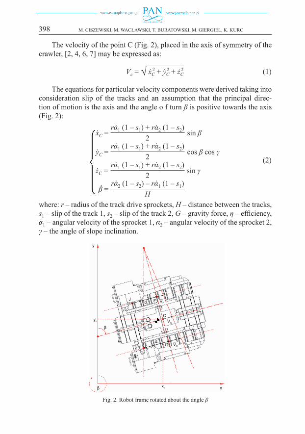
The velocity of the point C (Fig. 2), placed in the axis of symmetry of the crawler, [2, 4, 6, 7] may be expressed as:
Vc = √ xC2 + yC
2 + żC2. . (1)
The equations for particular velocity components were derived taking into consideration slip of the tracks and an assumption that the principal direc-tion of motion is the axis and the angle o f turn β is positive towards the axis (Fig. 2):
xC = sin β. rα1 (1 – s1) + rα2 (1 – s2)2
. .yC = cos β cos γ. rα1 (1 – s1) + rα2 (1 – s2)
2
. .
zC = sin γ. rα1 (1 – s1) + rα2 (1 – s2)2
. .
β =
. rα2 (1 – s2) – rα1 (1 – s1)H
. . (2)
where: r ‒ radius of the track drive sprockets, H ‒ distance between the tracks, s1 ‒ slip of the track 1, s2 ‒ slip of the track 2, G ‒ gravity force, η ‒ efficiency,
1 – angular velocity of the sprocket 1, 2 – angular velocity of the sprocket 2, γ ‒ the angle of slope inclination.
Fig. 2. Robot frame rotated about the angle β
399DESIGN, MODELLING AND LABORATORY TESTING OF A PIPE INSPECTION ROBOT
The slip of one track is calculated using the following formula:
s = (n – 1) ∙ dL
L (3)
where: n ‒ number of track treads in contact with the ground, dL ‒ track tread deformation, L ‒ length of a track load bearing segment.
The velocities of the points VF and VG located in the centres of tracks may be expressed as:
VF
2 = xF2 + yF
2 + żF2 . .
VG2 = xG
2 + yG2 + żG
2 . . (4)
xF = xC – 0.5Hβ sin β
yF = yC – 0.5Hβ cos β
żF = żC
.. .
... (5)
xG = xC – 0.5Hβ sin β
yG = yC – 0.5Hβ cos β
żG = żC
.. .
... (6)
The created kinematic model gives information about position and ori-entation of the robot. The kinematic model was used to design a preliminary control system for operation of the robot on flat surfaces. The next step in the design process was to select the appropriate drives for the positioning mecha-nisms that will allow the robot to move in horizontal and vertical pipes and ducts.
4. Multibody simulations
Multibody simulations aimed at determination of required torques for the positioning drives were performed using a simplified 3D model of the robot (Fig. 3) in the Autodesk Inventor Dynamic Simulation tool. An imposed mo-tion was defined for three drives by time dependent position input graphs, corresponding to various possible positions of a track with respect to the robot body. To simulate the worst case, maximum velocity of the servomotor located in the outer arm was used. The simplified model consisted of track assembly with total mass 1.5 kg, connected to the stationary body by bushings with fric-tion coefficient fb = 0.25, according to manufacturer’s specifications and ball bearings, where friction was neglected. It was sufficient to simulate only one side of the robot, because symmetric motion of track drives was assumed.

400 M. CISZEWSKI, M. WACŁAWSKI, T. BURATOWSKI, M. GIERGIEL, K. KURC
Fig. 3. Simplified 3D model of the robot used in the multibody simulations
Three simulations using the same trajectory were performed. The first one involved lifting the track and orienting it in space with respect to the stationary robot body oriented horizontally. The second simulation focused on a specific operation scenario of the robot, in which the extension forces exerted by the tracks on pipe walls were assumed to be equal to the maximum track payload (106 N). In the third simulation, the maximum payload forces were applied to the tracks and, addi tionally, the gravity was acting downwards the robot body, simulating operation in a vertical pipe.
The results shown in Fig. 4 are for the worst case scenario that is simula-tion of operation in a vertical pipe. The data indicate that the torques in the arm drives and ring drives do not exceed 4.2 Nm and 2 Nm, respectively. The results of the simulation were utilized to select servomotors and optimize ge-ometry of the track positioning system.
Fig. 4. Multibody simulations ‒ drive torques in vertical operation

401DESIGN, MODELLING AND LABORATORY TESTING OF A PIPE INSPECTION ROBOT
5. Prototype of the robot
A prototype of the robot was manufactured, based on the previously pre-pared CAD model. The prototype was equipped with light and an analogue CCTV camera. The total mass of the prototype is 6.5 kg.
Operation of the prototype can be controlled in different environments based on kinematic model and results of multibody simulations. The robot is capable of positioning its driving mechanism in various ways to adapt to de-sired inspection tasks. For the most compact configuration, the robot is able to operate in pipes of diameter 210 mm. In Fig. 5a, the robot is depicted in a hori-zontal ø235 mm pipe. The upper size limit of horizontal pipe is determined by the capabilities of the vision system.
The robot may also operate in pipes and ducts with a rectangular cross‒section. The same position is also utilized for inspection of flat surfaces.
Fig. 5. Operation environments: a) horizontal pipe, ø235 mm , b) vertical pipe, ø235 mm
A parallel extension of tracks is also possible for the robot structure. It may be utilized to operate in pipes or ducts with a rectangular or a circular cross-sections that are oriented in any direction, based on friction forces with respect to the walls. Fig. 5b shows the prototype during operation in a vertical pipe.
6. Measurements of power consumption
In order to estimate power consumption of the robot, the prototype was tested on flat surfaces (Fig. 6a) and in pipes with different diameters and ori-entations (Fig. 6b). Ten runs in each of three robot settings were performed to determine the minimum battery capacity required for various work scenarios. These tests will be an indispensable source of information for design of an autonomous version of the robot.

402 M. CISZEWSKI, M. WACŁAWSKI, T. BURATOWSKI, M. GIERGIEL, K. KURC
Fig. 6. Test environment: a) flat surface test, b) test in pipes
In the first setting, the robot structure was adjusted to operate on flat surface. The second type of environment was a horizontal pipe of diameter 242 mm, whilst the third experiment was performed in a vertical pipe of the same diameter. During all these tests, current drain was measured simultane-ously for 24 V and 6.4 V DC voltage. The higher voltage supplied the tracks and the lower voltage powered servomotors with robot control electronics.
Data acquisition was performed using a development board, equipped with two current sensors. Voltage measurements were realized with an univer-sal multimeter.
In order to determine measurement uncertainties, error analysis was per-formed. The voltage measured by the universal multimeter can be determined for range 0÷40V with the following limiting error (7):
ΔUlin = U ∙ 0.8% + 1 ∙ RES (7)
where U – value of measured voltage, RES – resolution of displayLimiting errors were calculated for measurements of voltages on power
supply cables of track drives (8) and positioning servomotors (9):
ΔUlin1 = 24.20 V ∙ 0.008 + 1 ∙ 0.01 = ±0.204 V (8)
ΔUlin2 = 6.45 V ∙ 0.008 + 1 ∙ 0.01 = ±0.062 V (9)
The limiting error that can appear during current measurements for the utilized sensors may be determined using equation (10):
ΔIlim = IR ∙ ETOT + [A]
VG
RG
S (10)
where: RG = 1024 – resolution of A/D transducer in development board, VG = 5 V – input voltage range of development board, IR – measurement range

403DESIGN, MODELLING AND LABORATORY TESTING OF A PIPE INSPECTION ROBOT
of particular current sensor, S – sensitivity of current sensor, ETOT = 1.5% – total error of current sensors
For measurements of current flow in power supply cables, limiting error values were calculated using equation (11) and (12) for track drives and posi-tioning servomotors accordingly:
ΔIlim1 = 5A ∙ 1,5% + = ±0.10 A
5V1024
0.185 V/A (11)
ΔIlim2 = 30A ∙ 1,5% + = ±0.52 A
5V1024
0.066 V/A (12)
The errors were taken into consideration during calculation of required capac-ity of rechargeable batteries used as a power supply for an autonomous prototype.
Results of the experiments indicate that the current drain during motion is within the operational parameters of the tracks. The difference of power consumption during motion in a horizontal pipe is within 10% margin with re-spect to operation on a flat surface as indicated in Fig. 7. During motion of the robot on a flat surface, large fluctuations of power consumption of positioning servomotors (Fig. 7 b) are observed. This is caused by an ununiform contact force between the tracks and the ground. During operation in a vertical pipe, the energy consumption is the highest among all experiments.
Fig. 7. Instantaneous power in various operation environments: a) flat surface, b) horizontal pipe, c) vertical pipe
a)
c)
b)
404 M. CISZEWSKI, M. WACŁAWSKI, T. BURATOWSKI, M. GIERGIEL, K. KURC
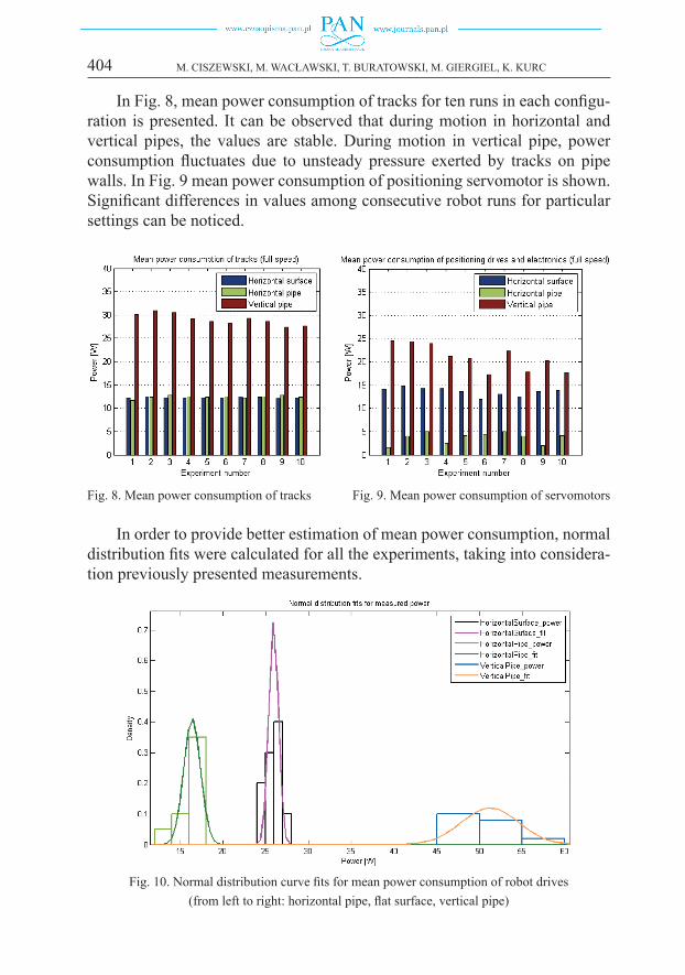
In Fig. 8, mean power consumption of tracks for ten runs in each configu-ration is presented. It can be observed that during motion in horizontal and vertical pipes, the values are stable. During motion in vertical pipe, power consumption fluctuates due to unsteady pressure exerted by tracks on pipe walls. In Fig. 9 mean power consumption of positioning servomotor is shown. Significant differences in values among consecutive robot runs for particular settings can be noticed.
Fig. 8. Mean power consumption of tracks Fig. 9. Mean power consumption of servomotors
In order to provide better estimation of mean power consumption, normal distribution fits were calculated for all the experiments, taking into considera-tion previously presented measurements.
Fig. 10. Normal distribution curve fits for mean power consumption of robot drives (from left to right: horizontal pipe, flat surface, vertical pipe)

405DESIGN, MODELLING AND LABORATORY TESTING OF A PIPE INSPECTION ROBOT
Figure 11 shows an estimate of operating time of the robot. It was as-sumed that the tracks and positioning servomotors are powered by separate lithium-polymer battery packs of total mass below 0.9 kg. It would be possible to attach a proper battery compartment on the back of the robot body without significant alteration of motion parameters.
Fig. 11. Mean operating time of robot on battery power supply
According to the data presented in Fig. 11, the robot should operate on selected battery power supply for 3 hours on flat surfaces, 6 hours in horizontal pipes and 2.5 hours in vertical pipes. This values would be sufficient for nor-mal operation scenarios during pipeline inspection.
7. Future work
Experiments with the track modules should be performed on different pipe and duct surfaces to provide values of the coefficient of friction that would al-low estimation of the required torque for the positioning drives.
An efficient control system that would allow an on-site adaptation to the work environment should be designed and implemented. The robot should be equipped with an Inertial Measurement Unit for determination of orien-tation of the robot in a pipe. One of the possible approaches to design the control system, based on the Kalman filter method, is presented in [1]. An algorithmic determination of the track treads deformation has to be devel-oped, based on particular surfaces to optimize positioning of the structure in the work environment. An autonomous prototype, powered by rechargeable

406 M. CISZEWSKI, M. WACŁAWSKI, T. BURATOWSKI, M. GIERGIEL, K. KURC
batteries would be designed, based on the performed energy consumption experiments.
8. Conclusions
This paper describes the design workflow from mathematical modelling of the robot, through CAD/CAE design and simulations and finally to a fully functional prototype. The market research of available pipe inspection robots showed that versatile inspection platforms are not available. The described robot was designed in order to address that problem.
A prototype was manufactured and its operation was verified with respect to the 3D model. Testing of the prototype proved that a reconfigurable robot platform is an advantageous solution to comprehensive pipe inspection. The proposed design eliminates the need for multiple devices dedicated to particu-lar types of pipelines. The measurements of energy consumption for different work scenarios of the robot were necessary to determine possibility of a design of an autonomous prototype, powered by rechargeable batteries.
Manuscript received by Editorial Board, October 16, 2014;final version, August 03, 2015
REFERENCES
[1] T. Buratowski et al.: A self-stabilising multipurpose single-wheel robot. Journal of Theoretical and Applied Mechanics, 2012, Vol. 50, No. 1, pp.99–118.
[2] Z. Burdziński.: Teoria ruchu pojazdu gąsienicowego (Theory of motion of a tracked vehicle). Warszawa, Wydawnictwa Komunikacji i Łączności, 1972 (in Polish).
[3] H. Choi, S. Roh.: In-pipe robot with active steering capability for moving inside of pipelines. Bioinspiration and Robotics Walking and Climbing Robots Red. M. K. Habib. Vienna, InTech.
[4] H. Dajniak.: Ciągniki. Teoria ruchu i konstruowanie (Tractors, theory of motion and design). Warszawa, Wydawnictwa Komunikacji i Łączności, 1985 (in Polish).
[5] K. Tadakuma et al.: Basic running test of the cylindrical tracked vehicle with sideways mobil-ity. Proc. IROS 2009 IEEE/RSJ International Conference on Intelligent Robots and Systems. 2009, pp.1678–1684.
[6] M. Trojnacki.: Modelowanie i symulacja ruchu mobilnego robota trzykołowego z napędem na przednie koła z uwzględnieniem poślizgu kół jezdnych (Modeling and simulation of motion of a three-wheeled mobile robot taking into account wheels slippage). Modelowanie Inżynierskie, 2011, Vol. 10, No. 41, pp.411–420 (in Polish).
[7] W. Żylski.: Kinematyka i dynamika mobilnych robotów kołowych (Kinematics and dynamics of wheeled mobile robots). Rzeszów, Oficyna Wydawnicza Politechniki Rzeszowskiej, 1996 (in Polish).
[8] Hydropulsion: Vertical Crawler Specification Sheet, http://www.hydropulsion.com/robotic-crawler-systems/vertical-crawler/ vertical-crawler.pdf, Accessed 09.01.2014
[9] Inuktun: Inuktun crawler vehicles, http://www.inuktun.com/crawler-vehicles, Accessed 12.01.2014[10] Ipek: ROVVER Brochure, http://www.ipek.at/fileadmin/FILES/downloads/ brochures/iPEK_
rovver_web_en.pdf, Accessed: 08.01.2014
407DESIGN, MODELLING AND LABORATORY TESTING OF A PIPE INSPECTION ROBOT
Projekt, modelowanie i testy laboratoryjne robota do inspekcji rurociągów
S t r e s z c z e n i e
Praca przedstawia projekt mobilnego gąsienicowego robota inspekcyjnego ze zmienną kon-figuracją układu napędowego. Robot jest stworzony do inspekcji okrągłych oraz kwadratowych rur i kanałów o orientacji pionowej oraz poziomej. W artykule opisany został proces wirtualnego prototypowania, podczas którego zwrócono uwagę na przystosowanie pozycji gąsienic do środo-wiska, w którym pracować będzie robot. Przedstawiono model matematyczny kinematyki robota oraz symulacje ruchu układu napędowego. Wynikiem prac była produkcja prototypu, który został przetestowany w rurach o średnicy przekraczającej 210 mm, co udokumentowano w artykule. Prze-prowadzone zostały również testy zużycia energii przez robota podczas przejazdów w trzech pod-stawowych konfiguracjach.