design of a block time bounded tdma (btb-tdma) mac protocol for uanets
TRANSCRIPT

Ocean Engineering 38 (2011) 2215–2226
Contents lists available at SciVerse ScienceDirect
Ocean Engineering
0029-80
doi:10.1
n Corr
E-m
poetwo
journal homepage: www.elsevier.com/locate/oceaneng
Design of a block time bounded TDMA (BTB-TDMA) MAC protocol for UANets
A-ra Cho a,n, Changho Yun b, Jong-won Park b, Yong-kon Lim b
a Marine Information and Communication Engineering Department, UST, 104 Sinseong-ro, Yuseong-gu, Daejeon 305-343, Republic of Koreab Ocean Engineering Research Department, MOERI-KORDI, 104 Sinseong-ro, Yuseong-gu, Daejeon 305-343, Republic of Korea
a r t i c l e i n f o
Article history:
Received 18 June 2010
Accepted 8 October 2011
Editor-in-Chief: A.I. Incecik(UANets). The BTB-TDMA determines transmission schedule of UNs based on UNs’ estimated propaga-
tion delays (EPDs), reflecting on UNs’ mobility. Furthermore, the scheduling algorithm gives UNs time
Available online 28 October 2011Keywords:
MAC
TDMA
Underwater acoustic network (UANet)
Mobile underwater node
18/$ - see front matter & 2011 Elsevier Ltd. A
016/j.oceaneng.2011.10.006
esponding author. Tel.: þ82 10 3839 9966.
ail addresses: [email protected] (Ar. Cho), sg
[email protected] (J.-w. Park), [email protected]
a b s t r a c t
In this paper, a Block Time Bounded Time Division Multiple Access (BTB-TDMA) medium access control
(MAC) protocol is proposed for mobile underwater nodes (UNs) in underwater acoustic networks
bound for data transfer with a unit of time block in order to reduce overall delay and avoid packet
collisions among UNs. To analyze the protocol’s performance, we divide BTB-TDMA into two cases, BTB-
TDMA considering EPDs (BTB-TDMA1) and BTB-TDMA without considering EPDs (BTB-TDMA2), to
show how the use of EPDs can improve overall network performance. In addition, we analytically derive
the channel access delay and channel utilization of STUMP (Kredo II et al., 2009) and TDMA, and
compare them with those of BTB-TDMA. The numerical analysis shows that BTB-TDMA1 can reduce
channel access delay by 20% and increase channel utilization by 35% at the maximum compared to
those of BTB-TDMA2. BTB-TDMA2 provides at least 14% lower channel access delay and 37% higher
channel utilization than STUMP. Furthermore, BTB-TDMA significantly outperforms TDMA, regardless
of the network environment.
& 2011 Elsevier Ltd. All rights reserved.
1. Introduction
We have developed many underwater acoustic network (UANet)applications, including oceanographic data collection, pollution mon-itoring, offshore exploration, disaster prevention, assisted navigation,and tactical surveillance (Ye et al., 2006). To efficiently realize theseapplications, we need to overcome the inherent limitations ofUANets, such as multipath interference, high bit error rates, sparserdeployment of nodes, and very limited energy consumption (Akyildizet al., 2005). In particular, the long propagation delay of acousticsignals (i.e., five-order higher than that of radio frequency (RF)signals) must be managed because it significantly affects the overallspeed of data transfer. In the network perspective, this long propaga-tion delay can be mitigated by controlling the medium access amongunderwater nodes (UNs). That is, an efficient medium access control(MAC) protocol would improve the delay performance of UANets,which controls UN transmission schedules by considering theirpropagation delays.
Previous literature in the field of underwater MAC protocolshas generally been divided into two areas (Chitre et al., 2008):one is contention-based MAC protocols, such as ALOHA, and
ll rights reserved.
[email protected] (C. Yun),
(Y.-k. Lim).
handshaking-based MAC protocols, and the other is contention-free MAC protocols, such as frequency division multiple access(FDMA), code division multiple access (CDMA), and time divisionmultiple access (TDMA)-based MAC protocols. Contention-basedprotocols could suffer intolerable long delays in underwater envir-onments and ALOHA-based MAC protocols (Chirdchoo et al., 2007;Syed et al., 2007) would have unbounded channel access delayscaused by the uncertain number of retransmissions. Handshaking-based protocols (Molins and Stojanovic, 2007; Guo et al., 2006;Peleato and Stojanovic, 2006; Shahabudeen et al., 2007) could alsoincur significant delay because of additional controlling signalsbefore transmission.
In view of delay performance, contention-free MAC protocolsare preferable to contention-based counterparts for UANets sincethey can avoid contention collision and message overhead such asrequest to send/clear to send (RTS/CTS), which exacerbate end-to-end delay significantly. Of the contention-free MAC protocols,FDMA-based MAC protocols (Nguyen et al., 2007) are not suitablefor UANets because of limited bandwidth. Regarding CDMA-basedMAC protocol (Pompili et al., 2009), they are very difficult to realizebecause of algorithm complexity and the near-far problem. TDMA-based MAC protocols can simply schedule transmission of UNs witha single frequency at the expense of its weakness of mobility.
To this end, we focus on a TDMA MAC protocol for UANets thatmanages propagation delays by reflecting on UNs’ mobility. PreviousTDMA-based protocols (Car and Adams, 2006; Guo et al., 2008;
A-ra Cho et al. / Ocean Engineering 38 (2011) 2215–22262216
Kredo II et al., 2009; Shin and Park, 2007) improve delay performanceand reduce the length of long guard time slots by using thepropagation delay information of UNs. However, as they are confinedto stationary UNs, they just consider UNs’ mobility due to oceancurrents and handle network topology change by a simple periodicbroadcast of mobility information. This method might be sufficient ina trivial case such as that nodes move slightly. Currently, most UANetapplications employ mobile UNs (e.g., Autonomous UnderwaterVehicles (AUVs), submarines, or gliders) that move with differentvelocity so that the change of network topology depends on UNs’velocity. TDMA-based MAC protocols only using periodic mobilityinformation can hardly deal with this various pace of change innetwork topology.
For the reason, we propose a Block Time Bounded TDMA (BTB-TDMA) that periodically determines the transmission schedules ofUNs using their estimated propagation delays (EPDs) during onecycle. A master node (MN) periodically calculates UN’s EPDs thatare determined by their previous position plus their predictablemoving distance based on present linear velocities. Then, the MNallocates time slots to UNs. In addition, the assigned transmissionschedule is time-bounded in the unit of a block which is anothertime unit as a time slot. The use of these blocks, referred to asblock time bounds (BTBs), enables the delay of data transfer to bereduced and data transfer collisions among UNs to be avoided.Thus, the BTB-TDMA protocol can reduce the length of one timeslot compared with classical TDMA protocols, the time slot lengthof which are equivalent to the maximum propagation delay of aUN. Hence, the BTB-TDMA protocol can improve overall delayperformance by considering the mobility of UNs.
The remainder of this paper is organized as follows. In Section2, the architecture of UANets is described. In Section 3, we explainour BTB-TDMA protocol, including the frame structure, theinitialization phase, and the data transmission phase. In Section4, the performance analysis of the BTB-TDMA protocol is executedin terms of channel access delay and channel utilization. Finally,we conclude this paper in Section 5.
1.1. Related work
As previously mentioned, large delay is one of the mostremarkable restrictions in UANets. In order to reduce large delay,various kinds of MAC protocols have been proposed. Particularly,recently several papers have suggested MAC protocols whichutilize inter-node propagation delay. Below, we introduce thosekinds of MAC protocol briefly.
In Car and Adams (2006), namely an ACMENet MAC protocol isTDMA based and a master-slave protocol intended for small(maximum of 13 slaves) underwater acoustic sensor network.The master nodes in ACMENet compute the propagation delays ofslave nodes and based on the computation, it schedules datatransmission. Accordingly, data packets from slave nodes arrive atthe master node consecutively, without collisions.
Gain-time and Guard-time (GT2) TDMA MAC (Shin and Park,2007) which can be applicable to clustered networks has tried toreduce the length of time slot by grouping nodes based on thedistance between a master and slave nodes. The distance group isclassified by a master node obtaining propagation delays of slavenodes and slave node is given its distance group. The Gain-timeand the Guard-time vary with the distance group and a masternode schedules data transfer adaptively taking the Gain-time andthe Guard-time into consideration.
The authors in Guo et al. (2008) have proposed a MAC protocolwhich also makes use of the propagation delay to resolve collisionproblem and reduce overhead of control-packet to save energy. Theydivide nodes of a network into two groups, children nodes and parentnodes. A child node calculates its propagation delay by obtaining
round trip time and transmits data at its own duty cycle consideringits propagation delay. A parent node periodically listen to the channelduring each cycle and sends an ACK packet upon receiving datapacket, and then it goes to sleep mode. They compared their MACprotocol to ACMENet protocol and showed simulation results that itcan offer low energy consumption while avoiding collisions.
Staggered TDMA underwater MAC protocol (STUMP) (Kredo IIet al., 2009) uses node propagation delay estimates to scheduleoverlapping transmissions without conflicts. It segments the areasurrounding a node into centric rings. The nodes subjected to aparticular ring only reserve the channel for the periods to transmitto ring width which is determined by the length of each time slot.With this scheme, STUMP reserves all the rings and each nodetransmits to multiple rings.
RIPT (Chirdchoo et al., 2010) and ROPA (Ng et al., 2010) arehandshaking-based MAC protocols which also account for nodes’round trip time by exchanging control packet prior to nodes’ sendingtheir data packets. The transmission schedules vary with predicteddata traffic, once the information of propagation delay is determined.
2. Architecture of UANets
In this section, we describe the overall network architecture ofour target UANet, as illustrated in Fig. 1. The UANet consists ofseveral UNs, MNs, central command ships, land stations, and asatellite. A UN has mobility and can be represented as divers,submarines, AUVs, etc. A UN is responsible for performing collabora-tive tasks in a given area. An MN is a stationary node located on thewater surface, similar to a buoy, and relays data from UNs to an MN,a land station, or a command ship. To accomplish this, an MN hastwo transceivers: an acoustic transceiver to communicate with UNsand a RF transceiver to communicate with another node floating onthe water surface. A central command ship is a mobile node onthe water surface that commands underwater missions and sendsdata gathered from MNs to a land station or a satellite. A centralcommand ship has several transceivers with RF frequencies, includ-ing a high frequency (HF) transceiver, a very-high frequency (VHF)transceiver, and an ultra-high or super-high frequency (UHF or SHF)satellite transceiver. A land station is connected to the terrestrialbackbone network in order to send various data from underwater toanother network domain.
The overall operation of the UANet can be summarized asfollows. A central command ship primarily orders MNs to obtainoceanographic data from UNs. Then, an MN begins to broadcastan acoustic initialization signal to UNs. After receiving the signal, aUN obtains its time slot from the MN for data transfer, and sends itsdata to the MN under a given MAC protocol. After receiving the data,the MN forwards the information to a central command ship, whichrelays the data to a land station. Finally, the land station sends thedata to many Internet subscribers via terrestrial backbone networks.
3. Proposed MAC: BTB-TDMA
In this section, we describe a BTB-TDMA MAC protocol thatconsists of two phases, the initialization phase and the datatransmission phase. To execute the BTB-TDMA protocol, we considerthe following assumptions:
�
All UNs are time-synchronized before they are deployedunderwater, and the timing synchronization will still holdwith the help of an internal timer. � The initial position of UNs is given by a GPS and their initialdepth is manipulated by wire cables attached to a ship whilethey are being deployed.

Time flowing directionData transmission phaseInitialization phase
SYNCtime slot
· · ·
SYNCtime slot
BEACONtime slot
DTB1
. . .DTBM-1
DTBM
DTS1
DTS2
. . .DTS
N. . .
τ τ +ττ τ τ +τ τb+τ2τ τ
)τ( ττ21cycle +⋅+⋅= N
τ = M · τ
DTB: Data time blockDTS: Data time slot
Fig. 2. Time flow graph of the BTB-TDMA protocol.
Fig. 1. An illustration of nodes in UANets.
A-ra Cho et al. / Ocean Engineering 38 (2011) 2215–2226 2217
�
When UNs are underwater, their linear velocities, whichdetermine their position information, are measured by anattitude heading reference system (AHRS) and a Dopplervelocity log (DVL). An AHRS is a three axis sensor that providesUNs with roll, pitch, and yaw information. A DVL determinesthe velocity vector of a UN moving underwater. � Our BTB-TDMA is targeted for a mobile on-demand applicationwhere multiple UNs are deployed and move around within thecommunication range of an MN without joining of new UNs.
� The switching time to change Rx/ Tx modes is negligible becausethe time of a few micro seconds is very small compared tounderwater propagation delay of a few seconds. Moreover, theprocessing delay time in a real system varies with systemperformance and we cannot specify the accurate delay time.
� UNs have different EPDs due to their random and sparse under-water deployment, thus the collision probability can be low.
� The speed of acoustic signals in UANets is assumed to be1500 m/s (Harris III and Zorzi, 2007; Shi et al., 2007).
Based on the above assumptions, we primarily focus on the framestructure of the BTB-TDMA protocol. The BTB-TDMA protocolphases can be explained as follows.
3.1. The frame structure of the BTB-TDMA protocol
As illustrated in Fig. 2, the frame structure of the BTB-TDMAprotocol can be divided into two types, the frame for the initialization
phase and that for the data transmission phase. Before explainingboth frames, we define the following parameters:
�
tmax is the maximum propagation delay of a network, whichallows all UNs to receive signals from an MN within itscommunication range. � t is the minimum required time to send a single data packet; itdepends on the length of a data packet and the data rate.
� tb is the length of a data time block, which is changeable. Theshorter the length of a data time block, the tighter the BTB-TDMA protocol timing bounds.
� M is the maximum number of data time blocks and is given astmax=tb. � N is the number of deployed UNs in a UANet application.First, the frame for the initialization phase is composed ofseveral time slots to send synchronization (SYNC) packets,referred to as a SYNC time slot. The length of a SYNC time slotis given as 2tmax, which is enough long for an MN to broadcastand receive responses from all UNs within its communicationrange, even though all UNs send their SYNC responses in a SYNCtime slot, as illustrated in Fig. 3.
Second, the frame for the data transmission phase consists of atime slot to send a BEACON packet, referred to as a BEACON timeslot, M time slots to determine the BTB of a UN, referred to as adata time block, and N time slots to send data packets, referred toas a data time slot. The length of a BEACON time slot is given as
1st SYNC time slot 2nd SYNC time slot
2τ2τmax
2· (Propagation Delay1)
2τmax
2 (P ti D l )
2· (Propagation Delay2)
2· (Propagation Delay1)Informs MN of UN1’s linear velocities
. . .MN
)1(1tΔ)2(1tΔ
UN1
)(
Propagation Delay of UN1
UN
Propagation Delay of UN1
MN estimates D2 duringbased on UN2’s SYNC response
)2(2tΔ
MN estimates D1 during
UN2
Propagation Propagation(MN estimates D1 duringbased on UN1’s SYNC response
Propagationdelay of UN2
Propagationdelay of UN2
)2(2tΔ
)1(1tΔ
: SYNC packet : SYNC response packet : SYNC time slot
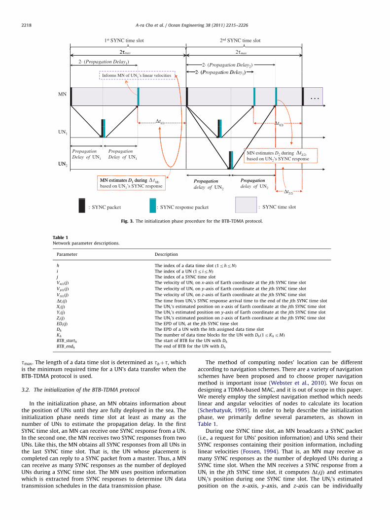
Fig. 3. The initialization phase procedure for the BTB-TDMA protocol.
Table 1Network parameter descriptions.
Parameter Description
h The index of a data time slot ð1rhrNÞ
i The index of a UN ð1r irNÞ
j The index of a SYNC time slot
VxðiÞðjÞ The velocity of UNi on x-axis of Earth coordinate at the jth SYNC time slot
VyðiÞðjÞ The velocity of UNi on y-axis of Earth coordinate at the jth SYNC time slot
VzðiÞðjÞ The velocity of UNi on z-axis of Earth coordinate at the jth SYNC time slot
DtiðjÞ The time from UNi’s SYNC response arrival time to the end of the jth SYNC time slot
XiðjÞ The UNi ’s estimated position on x-axis of Earth coordinate at the jth SYNC time slot
YiðjÞ The UNi ’s estimated position on y-axis of Earth coordinate at the jth SYNC time slot
ZiðjÞ The UNi ’s estimated position on z-axis of Earth coordinate at the jth SYNC time slot
EDiðjÞ The EPD of UNi at the jth SYNC time slot
Dh The EPD of a UN with the hth assigned data time slot
Kh The number of data time blocks for the UN with Dhð1rKh rMÞ
BTB_starth The start of BTB for the UN with Dh
BTB_endh The end of BTB for the UN with Dh
A-ra Cho et al. / Ocean Engineering 38 (2011) 2215–22262218
tmax. The length of a data time slot is determined as tbþt, whichis the minimum required time for a UN’s data transfer when theBTB-TDMA protocol is used.
3.2. The initialization of the BTB-TDMA protocol
In the initialization phase, an MN obtains information aboutthe position of UNs until they are fully deployed in the sea. Theinitialization phase needs time slot at least as many as thenumber of UNs to estimate the propagation delay. In the firstSYNC time slot, an MN can receive one SYNC response from a UN.In the second one, the MN receives two SYNC responses from twoUNs. Like this, the MN obtains all SYNC responses from all UNs inthe last SYNC time slot. That is, the UN whose placement iscompleted can reply to a SYNC packet from a master. Thus, a MNcan receive as many SYNC responses as the number of deployedUNs during a SYNC time slot. The MN uses position informationwhich is extracted from SYNC responses to determine UN datatransmission schedules in the data transmission phase.
The method of computing nodes’ location can be differentaccording to navigation schemes. There are a variety of navigationschemes have been proposed and to choose proper navigationmethod is important issue (Webster et al., 2010). We focus ondesigning a TDMA-based MAC, and it is out of scope in this paper.We merely employ the simplest navigation method which needslinear and angular velocities of nodes to calculate its location(Scherbatyuk, 1995). In order to help describe the initializationphase, we primarily define several parameters, as shown inTable 1.
During one SYNC time slot, an MN broadcasts a SYNC packet(i.e., a request for UNs’ position information) and UNs send theirSYNC responses containing their position information, includinglinear velocities (Fossen, 1994). That is, an MN may receive asmany SYNC responses as the number of deployed UNs during aSYNC time slot. When the MN receives a SYNC response from aUNi in the jth SYNC time slot, it computes DtiðjÞ and estimatesUNi’s position during one SYNC time slot. The UNi’s estimatedposition on the x-axis, y-axis, and z-axis can be individually
max
b b b b b b b b b b b
The 1ST cycle of the data transmission phase
BTBstart
BTBstart
D K
D K
BTBend
BTBend
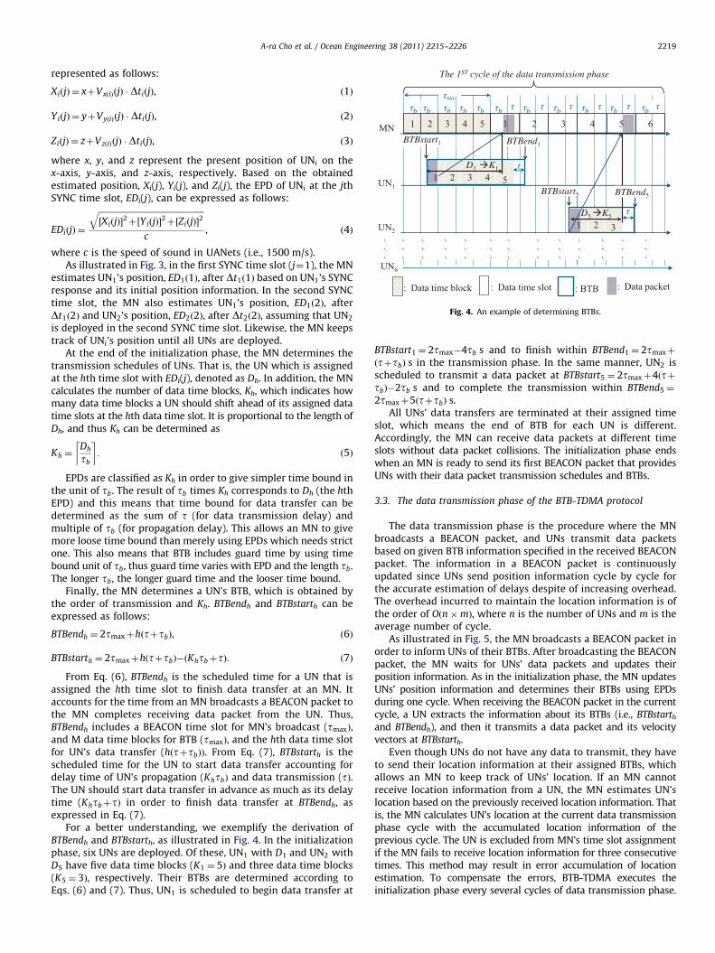
Fig. 4. An example of determining BTBs.
A-ra Cho et al. / Ocean Engineering 38 (2011) 2215–2226 2219
represented as follows:
XiðjÞ ¼ xþVxðiÞðjÞ � DtiðjÞ, ð1Þ
YiðjÞ ¼ yþVyðiÞðjÞ � DtiðjÞ, ð2Þ
ZiðjÞ ¼ zþVzðiÞðjÞ � DtiðjÞ, ð3Þ
where x, y, and z represent the present position of UNi on thex-axis, y-axis, and z-axis, respectively. Based on the obtainedestimated position, Xi(j), Yi(j), and Zi(j), the EPD of UNi at the jthSYNC time slot, EDi(j), can be expressed as follows:
EDiðjÞ ¼
ffiffiffiffiffiffiffiffiffiffiffiffiffiffiffiffiffiffiffiffiffiffiffiffiffiffiffiffiffiffiffiffiffiffiffiffiffiffiffiffiffiffiffiffiffiffiffiffiffiffiffi½XiðjÞ�
2þ½YiðjÞ�2þ½ZiðjÞ�
2q
c, ð4Þ
where c is the speed of sound in UANets (i.e., 1500 m/s).As illustrated in Fig. 3, in the first SYNC time slot (j¼1), the MN
estimates UN1’s position, ED1ð1Þ, after Dt1ð1Þ based on UN1’s SYNCresponse and its initial position information. In the second SYNCtime slot, the MN also estimates UN1’s position, ED1ð2Þ, afterDt1ð2Þ and UN2’s position, ED2ð2Þ, after Dt2ð2Þ, assuming that UN2
is deployed in the second SYNC time slot. Likewise, the MN keepstrack of UNi’s position until all UNs are deployed.
At the end of the initialization phase, the MN determines thetransmission schedules of UNs. That is, the UN which is assignedat the hth time slot with EDi(j), denoted as Dh. In addition, the MNcalculates the number of data time blocks, Kh, which indicates howmany data time blocks a UN should shift ahead of its assigned datatime slots at the hth data time slot. It is proportional to the length ofDh, and thus Kh can be determined as
Kh ¼Dh
tb
� �: ð5Þ
EPDs are classified as Kh in order to give simpler time bound inthe unit of tb. The result of tb times Kh corresponds to Dh (the hthEPD) and this means that time bound for data transfer can bedetermined as the sum of t (for data transmission delay) andmultiple of tb (for propagation delay). This allows an MN to givemore loose time bound than merely using EPDs which needs strictone. This also means that BTB includes guard time by using timebound unit of tb, thus guard time varies with EPD and the length tb.The longer tb, the longer guard time and the looser time bound.
Finally, the MN determines a UN’s BTB, which is obtained bythe order of transmission and Kh. BTBendh and BTBstarth can beexpressed as follows:
BTBendh ¼ 2tmaxþhðtþtbÞ, ð6Þ
BTBstarth ¼ 2tmaxþhðtþtbÞ�ðKhtbþtÞ: ð7Þ
From Eq. (6), BTBendh is the scheduled time for a UN that isassigned the hth time slot to finish data transfer at an MN. Itaccounts for the time from an MN broadcasts a BEACON packet tothe MN completes receiving data packet from the UN. Thus,BTBendh includes a BEACON time slot for MN’s broadcast (tmaxÞ,and M data time blocks for BTB (tmaxÞ, and the hth data time slotfor UN’s data transfer (hðtþtbÞÞ. From Eq. (7), BTBstarth is thescheduled time for the UN to start data transfer accounting fordelay time of UN’s propagation (KhtbÞ and data transmission (tÞ.The UN should start data transfer in advance as much as its delaytime (KhtbþtÞ in order to finish data transfer at BTBendh, asexpressed in Eq. (7).
For a better understanding, we exemplify the derivation ofBTBendh and BTBstarth, as illustrated in Fig. 4. In the initializationphase, six UNs are deployed. Of these, UN1 with D1 and UN2 withD5 have five data time blocks (K1 ¼ 5Þ and three data time blocks(K5 ¼ 3Þ, respectively. Their BTBs are determined according toEqs. (6) and (7). Thus, UN1 is scheduled to begin data transfer at
BTBstart1 ¼ 2tmax�4tb s and to finish within BTBend1 ¼ 2tmaxþ
ðtþtbÞ s in the transmission phase. In the same manner, UN2 isscheduled to transmit a data packet at BTBstart5 ¼ 2tmaxþ4ðtþtbÞ�2tb s and to complete the transmission within BTBend5 ¼
2tmaxþ5ðtþtbÞ s.All UNs’ data transfers are terminated at their assigned time
slot, which means the end of BTB for each UN is different.Accordingly, the MN can receive data packets at different timeslots without data packet collisions. The initialization phase endswhen an MN is ready to send its first BEACON packet that providesUNs with their data packet transmission schedules and BTBs.
3.3. The data transmission phase of the BTB-TDMA protocol
The data transmission phase is the procedure where the MNbroadcasts a BEACON packet, and UNs transmit data packetsbased on given BTB information specified in the received BEACONpacket. The information in a BEACON packet is continuouslyupdated since UNs send position information cycle by cycle forthe accurate estimation of delays despite of increasing overhead.The overhead incurred to maintain the location information is ofthe order of Oðn�mÞ, where n is the number of UNs and m is theaverage number of cycle.
As illustrated in Fig. 5, the MN broadcasts a BEACON packet inorder to inform UNs of their BTBs. After broadcasting the BEACONpacket, the MN waits for UNs’ data packets and updates theirposition information. As in the initialization phase, the MN updatesUNs’ position information and determines their BTBs using EPDsduring one cycle. When receiving the BEACON packet in the currentcycle, a UN extracts the information about its BTBs (i.e., BTBstarth
and BTBendh), and then it transmits a data packet and its velocityvectors at BTBstarth.
Even though UNs do not have any data to transmit, they haveto send their location information at their assigned BTBs, whichallows an MN to keep track of UNs’ location. If an MN cannotreceive location information from a UN, the MN estimates UN’slocation based on the previously received location information. Thatis, the MN calculates UN’s location at the current data transmissionphase cycle with the accumulated location information of theprevious cycle. The UN is excluded from MN’s time slot assignmentif the MN fails to receive location information for three consecutivetimes. This method may result in error accumulation of locationestimation. To compensate the errors, BTB-TDMA executes theinitialization phase every several cycles of data transmission phase.
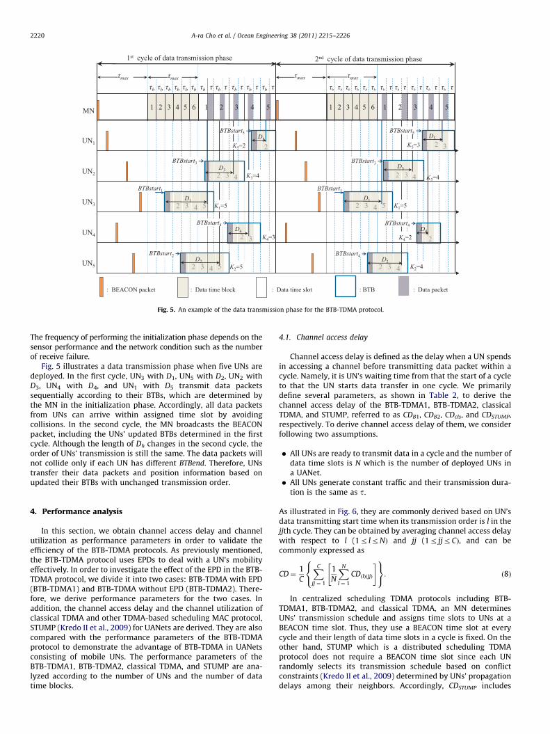
Fig. 5. An example of the data transmission phase for the BTB-TDMA protocol.
A-ra Cho et al. / Ocean Engineering 38 (2011) 2215–22262220
The frequency of performing the initialization phase depends on thesensor performance and the network condition such as the numberof receive failure.
Fig. 5 illustrates a data transmission phase when five UNs aredeployed. In the first cycle, UN3 with D1, UN5 with D2, UN2 withD3, UN4 with D4, and UN1 with D5 transmit data packetssequentially according to their BTBs, which are determined bythe MN in the initialization phase. Accordingly, all data packetsfrom UNs can arrive within assigned time slot by avoidingcollisions. In the second cycle, the MN broadcasts the BEACONpacket, including the UNs’ updated BTBs determined in the firstcycle. Although the length of Dh changes in the second cycle, theorder of UNs’ transmission is still the same. The data packets willnot collide only if each UN has different BTBend. Therefore, UNstransfer their data packets and position information based onupdated their BTBs with unchanged transmission order.
4. Performance analysis
In this section, we obtain channel access delay and channelutilization as performance parameters in order to validate theefficiency of the BTB-TDMA protocols. As previously mentioned,the BTB-TDMA protocol uses EPDs to deal with a UN’s mobilityeffectively. In order to investigate the effect of the EPD in the BTB-TDMA protocol, we divide it into two cases: BTB-TDMA with EPD(BTB-TDMA1) and BTB-TDMA without EPD (BTB-TDMA2). There-fore, we derive performance parameters for the two cases. Inaddition, the channel access delay and the channel utilization ofclassical TDMA and other TDMA-based scheduling MAC protocol,STUMP (Kredo II et al., 2009) for UANets are derived. They are alsocompared with the performance parameters of the BTB-TDMAprotocol to demonstrate the advantage of BTB-TDMA in UANetsconsisting of mobile UNs. The performance parameters of theBTB-TDMA1, BTB-TDMA2, classical TDMA, and STUMP are ana-lyzed according to the number of UNs and the number of datatime blocks.
4.1. Channel access delay
Channel access delay is defined as the delay when a UN spendsin accessing a channel before transmitting data packet within acycle. Namely, it is UN’s waiting time from that the start of a cycleto that the UN starts data transfer in one cycle. We primarilydefine several parameters, as shown in Table 2, to derive thechannel access delay of the BTB-TDMA1, BTB-TDMA2, classicalTDMA, and STUMP, referred to as CDB1, CDB2, CDcls, and CDSTUMP,respectively. To derive channel access delay of them, we considerfollowing two assumptions.
�
All UNs are ready to transmit data in a cycle and the number ofdata time slots is N which is the number of deployed UNs ina UANet. � All UNs generate constant traffic and their transmission dura-tion is the same as t.
As illustrated in Fig. 6, they are commonly derived based on UN’sdata transmitting start time when its transmission order is l in thejjth cycle. They can be obtained by averaging channel access delaywith respect to l (1r lrNÞ and jj (1r jjrCÞ, and can becommonly expressed as
CD¼1
C
XC
jj ¼ 1
1
N
XN
l ¼ 1
CDðlÞðjjÞ
" #8<:
9=;: ð8Þ
In centralized scheduling TDMA protocols including BTB-TDMA1, BTB-TDMA2, and classical TDMA, an MN determinesUNs’ transmission schedule and assigns time slots to UNs at aBEACON time slot. Thus, they use a BEACON time slot at everycycle and their length of data time slots in a cycle is fixed. On theother hand, STUMP which is a distributed scheduling TDMAprotocol does not require a BEACON time slot since each UNrandomly selects its transmission schedule based on conflictconstraints (Kredo II et al., 2009) determined by UNs’ propagationdelays among their neighbors. Accordingly, CDSTUMP includes
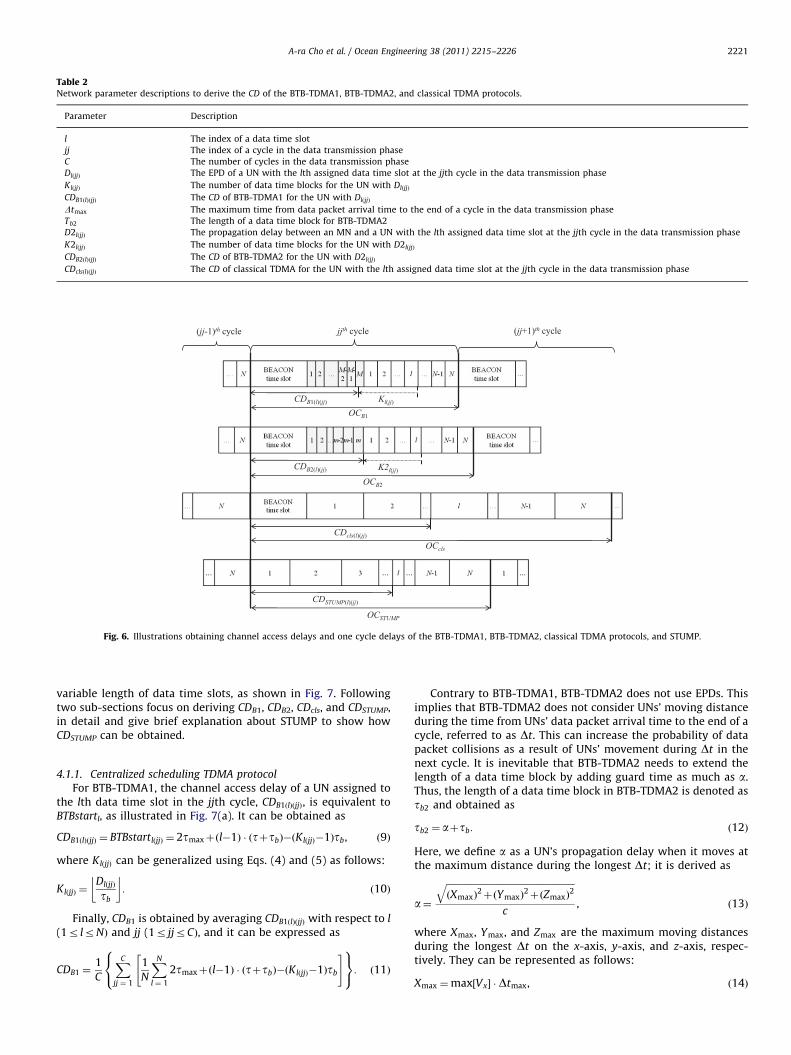
Table 2Network parameter descriptions to derive the CD of the BTB-TDMA1, BTB-TDMA2, and classical TDMA protocols.
Parameter Description
l The index of a data time slot
jj The index of a cycle in the data transmission phase
C The number of cycles in the data transmission phase
DlðjjÞ The EPD of a UN with the lth assigned data time slot at the jjth cycle in the data transmission phase
KlðjjÞ The number of data time blocks for the UN with DlðjjÞ
CDB1ðlÞðjjÞ The CD of BTB-TDMA1 for the UN with DlðjjÞ
Dtmax The maximum time from data packet arrival time to the end of a cycle in the data transmission phase
Tb2 The length of a data time block for BTB-TDMA2
D2lðjjÞ The propagation delay between an MN and a UN with the lth assigned data time slot at the jjth cycle in the data transmission phase
K2lðjjÞ The number of data time blocks for the UN with D2lðjjÞ
CDB2ðlÞðjjÞ The CD of BTB-TDMA2 for the UN with D2lðjjÞ
CDclsðlÞðjjÞ The CD of classical TDMA for the UN with the lth assigned data time slot at the jjth cycle in the data transmission phase
Fig. 6. Illustrations obtaining channel access delays and one cycle delays of the BTB-TDMA1, BTB-TDMA2, classical TDMA protocols, and STUMP.
A-ra Cho et al. / Ocean Engineering 38 (2011) 2215–2226 2221
variable length of data time slots, as shown in Fig. 7. Followingtwo sub-sections focus on deriving CDB1, CDB2, CDcls, and CDSTUMP,in detail and give brief explanation about STUMP to show howCDSTUMP can be obtained.
4.1.1. Centralized scheduling TDMA protocol
For BTB-TDMA1, the channel access delay of a UN assigned tothe lth data time slot in the jjth cycle, CDB1ðlÞðjjÞ, is equivalent toBTBstartl, as illustrated in Fig. 7(a). It can be obtained as
CDB1ðlÞðjjÞ ¼ BTBstartlðjjÞ ¼ 2tmaxþðl�1Þ � ðtþtbÞ�ðKlðjjÞ�1Þtb, ð9Þ
where KlðjjÞ can be generalized using Eqs. (4) and (5) as follows:
KlðjjÞ ¼DlðjjÞ
tb
� �: ð10Þ
Finally, CDB1 is obtained by averaging CDB1ðlÞðjjÞ with respect to l
(1r lrNÞ and jj (1r jjrCÞ, and it can be expressed as
CDB1 ¼1
C
XC
jj ¼ 1
1
N
XN
l ¼ 1
2tmaxþðl�1Þ � ðtþtbÞ�ðKlðjjÞ�1Þtb
" #8<:
9=;: ð11Þ
Contrary to BTB-TDMA1, BTB-TDMA2 does not use EPDs. Thisimplies that BTB-TDMA2 does not consider UNs’ moving distanceduring the time from UNs’ data packet arrival time to the end of acycle, referred to as Dt. This can increase the probability of datapacket collisions as a result of UNs’ movement during Dt in thenext cycle. It is inevitable that BTB-TDMA2 needs to extend thelength of a data time block by adding guard time as much as a.Thus, the length of a data time block in BTB-TDMA2 is denoted astb2 and obtained as
tb2 ¼ aþtb: ð12Þ
Here, we define a as a UN’s propagation delay when it moves atthe maximum distance during the longest Dt; it is derived as
a¼
ffiffiffiffiffiffiffiffiffiffiffiffiffiffiffiffiffiffiffiffiffiffiffiffiffiffiffiffiffiffiffiffiffiffiffiffiffiffiffiffiffiffiffiffiffiffiffiffiffiffiffiffiffiffiffiffiðXmaxÞ
2þðYmaxÞ
2þðZmaxÞ
2q
c, ð13Þ
where Xmax, Ymax, and Zmax are the maximum moving distancesduring the longest Dt on the x-axis, y-axis, and z-axis, respec-tively. They can be represented as follows:
Xmax ¼max½Vx� � Dtmax, ð14Þ
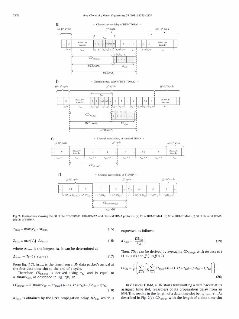
Fig. 7. Illustrations showing the CD of the BTB-TDMA1, BTB-TDMA2, and classical TDMA protocols. (a) CD of BTB-TDMA1. (b) CD of BTB-TDMA2. (c) CD of classical TDMA.
(d) CD of STUMP.
A-ra Cho et al. / Ocean Engineering 38 (2011) 2215–22262222
Ymax ¼max½Vy� �Dtmax, ð15Þ
Zmax ¼max½Vz� � Dtmax, ð16Þ
where Dtmax is the longest Dt. It can be determined as
Dtmax ¼ ðN�1Þ � ðtbþtÞ: ð17Þ
From Eq. (17), Dtmax is the time from a UN data packet’s arrival atthe first data time slot to the end of a cycle.
Therefore, CDB2ðlÞðjjÞ is derived using tb2 and is equal toBTBstart2lðjjÞ, as described in Fig. 7(b). In
CDB2ðlÞðjjÞ ¼ BTBstart2lðjjÞ ¼ 2tmaxþðl�1Þ � ðtþtb2Þ�ðK2lðjjÞ�1Þtb2,
ð18Þ
K2lðjjÞ is obtained by the UN’s propagation delay, D2lðjjÞ, which is
expressed as follows:
K2lðjjÞ ¼D2lðjjÞ
tb2
� �: ð19Þ
Then, CDB2 can be derived by averaging CDB2ðlÞðjjÞ with respect to l
(1r lrNÞ and jj (1r jjrCÞ
CDB2 ¼1
C
XC
jj ¼ 1
1
N
XN
l ¼ 1
2tmaxþðl�1Þ � ðtþtb2Þ�ðK2lðjjÞ�1Þtb2
" #8<:
9=;:ð20Þ
In classical TDMA, a UN starts transmitting a data packet at itsassigned time slot, regardless of its propagation delay from anMN. This results in the length of a data time slot being tmaxþt. Asdescribed in Fig. 7(c), CDclsðlÞðjjÞ with the length of a data time slot
Table 3Network parameter descriptions to derive the CD of the STUMP.
Parameter Description
nr A reference UN
nc A competing UN with nr
n.start UN’s transmission start time slot
n.duration The required time slots for UN’s transmission
nrnc :PRP Propagation delay between nr and nc
nr :PRP Propagation delay between nr ’ destination and nr
nc :PRP Propagation delay between nr ’ destination and nc
T The unit of a time slot
k The index of a nr ð1rkrNÞ
ncðkÞ:PRPðlÞðjjÞ Propagation delay between nrðkÞ ’ destination and ncðkÞ with the lth transmission order in the jjth cycle
nrðkÞncðkÞ:PRPðlÞðjjÞ Propagation delay between nrðkÞ and ncðkÞ with the lth transmission order in the jjth cycle
A-ra Cho et al. / Ocean Engineering 38 (2011) 2215–2226 2223
can be represented as
CDclsðlÞðjjÞ ¼ ðl�1Þ � ðtmaxþtÞþtmax: ð21Þ
Accordingly, CDcls can be derived by averaging CDclsðlÞðjjÞ withrespect to l (1r lrNÞ and jj (1r jjrCÞ, as follows:
CDcls ¼1
C
XC
jj ¼ 1
1
N
XN
l ¼ 1
ðl�1Þ � ðtmaxþtÞþtmax
" #8<:
9=;: ð22Þ
4.1.2. Distributed scheduling TDMA protocol
In order to derive channel access delay of STUMP, CDSTUMP, weneed to consider STUMP’s transmission scheduling constraints forunderwater acoustic networks. There are four possible schedulingconstraints; TX–TX conflict, TX–RX conflict, RX–RX conflict, and TX–RX–TX conflict (Kredo II et al., 2009). We primarily introducescheduling constraints for each conflicting case, and then showthat all the cases can be represented in a unified way and give twoinequality equations to resolve all possible conflicts. To begin with,we define several parameters required for analysis of STUMP, asshown in Table 3.
�
TX–TX conflict: This case occurs two transmissions share thesame source (nr’s source¼nc’s source) and but with differentdestinations. They assume that the nodes are equipped with asingle physical interface and therefore nodes cannot transmitmultiple packets simultaneouslynr :startZnc :startþnc:duration, ð23Þ
nr :startþnr :durationrnc :start, ð24Þ
�
TX–RX conflict: A node cannot receive a packet when it istransmitting another packet. Thus, nr should start transmissionafter finishing reception from nc, Eq. (25), or nr should startreceiving after finishing transmission, Eq. (26)nr :startZnc :startþnc:durationþnrnc:PRP
T, ð25Þ
nr :startþnr :durationþnr :PRP
Trnc:startþ
nrnc :PRP
T: ð26Þ
�
RX–RX conflict: Two transmissions share the same destination(nr’s destination¼nc’s destination). nr’s packet should arrive atthe destination after the destination node finishing receptionfrom nc, Eq. (27), or contrarily, Eq. (28)nr :startþnr :PRP
TZnc :startþnc :durationþ
nc :PRP
T, ð27Þ
nr :startþnr :durationþnr :PRP
Trnc :startþ
nc:PRP
T: ð28Þ
�
TX–RX–TX conflict: One transmission from nc interferes withthe other transmission at nr’s destination. This case is nearlyidentical to the RX–RX conflict.Eqs. (23)–(28) illustrate how one transmission task can be scheduledafter another transmission task without conflicts. Namely, theyconsider only two successive transmission tasks in the network.However, we should consider all transmission tasks in the networkin order to compare STUMP with our proposed MAC fairly. Thus, wegeneralize the Eqs. (23)–(28) in a unified way in order to deal alltransmission tasks. From Eqs. (23), (25) and (27), the equations canbe simplified in a single equation, Eq. (29), and we can also writeEqs. (24), (26) and (28) as expressed in Eq. (30).
nr :startZnc:startþnc :durationþmaxnc:PRP
T�
nr :PRP
T
� �,nrnc :PRP
T
,
ð29Þ
nr :startþnr :durationrnc:startþminnc:PRP
T�
nr :PRP
T
� �,nrnc:PRP
T
:
ð30Þ
We can calculate nr’s transmission start time slot from Eq. (29)which is on the basis of that nr starts transmission after previoustransmission from the other competing UN, nc is completed. Onthe contrary, Eq. (30) bounds nr’s transmission end time slot ifnext transmission start time from nc is determined, which isbased on that nr starts transmission first and finishes its transmis-sion then nc transmits data. Aforementioned, all UNs’ transmis-sion duration are identical, thus nr’s transmission end time slotcan be obtained without using Eq. (30). To end this, by usingEq. (29), we can calculate all UNs’ length of time slots in a cycle,which varies with which nr is selected among N UNs. Accordingly,it is necessary to consider all cases of nrðkÞ:start correspondingto selected reference UNs and multiply nrðkÞ:start with the unit oftime slot, T, in order to derive CDSTUMP. The result of multiplyingnrðkÞ:start with T, nrðkÞ:s is expressed as
nrðkÞ:s¼ T � ½nrðkÞ:start�: ð31Þ
Using Eqs. (29) and (31) and the fact that all UNs’ transmissionduration are the same as t, we can obtain UN’s transmission starttime with lth transmission order in the jjth cycle, nrðkÞ:sðlÞðjjÞ. It canbe represented as follows:
nrðkÞ:sðlÞðjjÞ ¼ ncðkÞ:sðl�1ÞðjjÞ þtþPkðl�1ÞðjjÞ, ð32Þ
where ncðkÞ:sð1ÞðjjÞ ¼ 0, and Pkðl�1ÞðjjÞ can be expressed as
PkðlÞðjjÞ ¼maxfðncðkÞ:PRPðlÞðjjÞ�nrðkÞ:PRPÞ,nrðkÞncðkÞ:PRPðlÞðjjÞg: ð33Þ
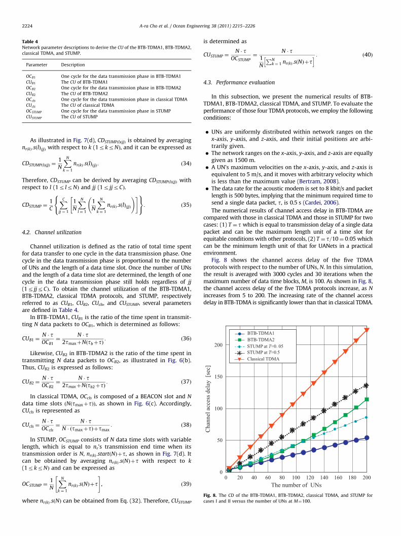
Table 4Network parameter descriptions to derive the CU of the BTB-TDMA1, BTB-TDMA2,
classical TDMA, and STUMP.
Parameter Description
OCB1 One cycle for the data transmission phase in BTB-TDMA1
CUB1 The CU of BTB-TDMA1
OCB2 One cycle for the data transmission phase in BTB-TDMA2
CUB2 The CU of BTB-TDMA2
OCcls One cycle for the data transmission phase in classical TDMA
CUcls The CU of classical TDMA
OCSTUMP One cycle for the data transmission phase in STUMP
CUSTUMP The CU of STUMP
Fig. 8. The CD of the BTB-TDMA1, BTB-TDMA2, classical TDMA, and STUMP for
cases I and II versus the number of UNs at M¼100.
A-ra Cho et al. / Ocean Engineering 38 (2011) 2215–22262224
As illustrated in Fig. 7(d), CDSTUMPðlÞðjjÞ is obtained by averagingnrðkÞ:sðlÞðjjÞ with respect to k (1rkrNÞ, and it can be expressed as
CDSTUMPðlÞðjjÞ ¼1
N
XN
k ¼ 1
nrðkÞ:sðlÞðjjÞ: ð34Þ
Therefore, CDSTUMP can be derived by averaging CDSTUMPðlÞðjjÞ withrespect to l (1r lrNÞ and jj (1r jjrCÞ.
CDSTUMP ¼1
C
XC
jj ¼ 1
1
N
XN
l ¼ 1
1
N
XN
k ¼ 1
nrðkÞ:sðlÞðjjÞ
!" #8<:
9=;: ð35Þ
4.2. Channel utilization
Channel utilization is defined as the ratio of total time spentfor data transfer to one cycle in the data transmission phase. Onecycle in the data transmission phase is proportional to the numberof UNs and the length of a data time slot. Once the number of UNsand the length of a data time slot are determined, the length of onecycle in the data transmission phase still holds regardless of jj
(1r jjrCÞ. To obtain the channel utilization of the BTB-TDMA1,BTB-TDMA2, classical TDMA protocols, and STUMP, respectivelyreferred to as CUB1, CUB2, CUcls, and CUSTUMP, several parametersare defined in Table 4.
In BTB-TDMA1, CUB1 is the ratio of the time spent in transmit-ting N data packets to OCB1, which is determined as follows:
CUB1 ¼N � tOCB1
¼N � t
2tmaxþNðtbþtÞ: ð36Þ
Likewise, CUB2 in BTB-TDMA2 is the ratio of the time spent intransmitting N data packets to OCB2, as illustrated in Fig. 6(b).Thus, CUB2 is expressed as follows:
CUB2 ¼N � tOCB2
¼N � t
2tmaxþNðtb2þtÞ: ð37Þ
In classical TDMA, OCcls is composed of a BEACON slot and N
data time slots ðNðtmaxþtÞÞ, as shown in Fig. 6(c). Accordingly,CUcls is represented as
CUcls ¼N � tOCcls
¼N � t
N � ðtmaxþtÞþtmax: ð38Þ
In STUMP, OCSTUMP consists of N data time slots with variablelength, which is equal to nr’s transmission end time when itstransmission order is N, nrðkÞ:startðNÞþt, as shown in Fig. 7(d). Itcan be obtained by averaging nrðkÞ:sðNÞþt with respect to k
(1rkrNÞ and can be expressed as
OCSTUMP ¼1
N
XN
k ¼ 1
nrðkÞ:sðNÞþt" #
, ð39Þ
where nrðkÞ:sðNÞ can be obtained from Eq. (32). Therefore, CUSTUMP
is determined as
CUSTUMP ¼N � t
OCSTUMP¼
N � t1
N
PNk ¼ 1 nrðkÞ:sðNÞþt
h i : ð40Þ
4.3. Performance evaluation
In this subsection, we present the numerical results of BTB-TDMA1, BTB-TDMA2, classical TDMA, and STUMP. To evaluate theperformance of those four TDMA protocols, we employ the followingconditions:
�
UNs are uniformly distributed within network ranges on thex-axis, y-axis, and z-axis, and their initial positions are arbi-trarily given. � The network ranges on the x-axis, y-axis, and z-axis are equallygiven as 1500 m.
� A UN’s maximum velocities on the x-axis, y-axis, and z-axis isequivalent to 5 m/s, and it moves with arbitrary velocity whichis less than the maximum value (Bertram, 2008).
� The data rate for the acoustic modem is set to 8 kbit/s and packetlength is 500 bytes, implying that the minimum required time tosend a single data packet, t, is 0.5 s (Cardei, 2006).
The numerical results of channel access delay in BTB-TDMA arecompared with those in classical TDMA and those in STUMP for twocases: (1) T ¼ t which is equal to transmission delay of a single datapacket and can be the maximum length unit of a time slot forequitable conditions with other protocols, (2) T ¼ t=10¼ 0:05 whichcan be the minimum length unit of that for UANets in a practicalenvironment.
Fig. 8 shows the channel access delay of the five TDMAprotocols with respect to the number of UNs, N. In this simulation,the result is averaged with 3000 cycles and 30 iterations when themaximum number of data time blocks, M, is 100. As shown in Fig. 8,the channel access delay of the five TDMA protocols increase, as N
increases from 5 to 200. The increasing rate of the channel accessdelay in BTB-TDMA is significantly lower than that in classical TDMA.
A-ra Cho et al. / Ocean Engineering 38 (2011) 2215–2226 2225
Overall, it is shown that BTB-TDMA1 outperform STUMP for cases Iand II regardless of N and the performance of BTB-TDMA1 becomespredominant as N increases. On the contrary, the channel accessdelay of BTB-TDMA2 is slightly lower than that of STUMP for case IIwhen Nr110 and finally longer than that of STUMP for case II whenN4110. This implies that BTB-TDMA1 can reduce the average delayto access a channel compared to classical TDMA and STUMP and itcan further decrease channel access delay when EPD is considered. Inaddition, the channel access delay difference between BTB-TDMA1and the other four TDMA protocols larger as N increases.
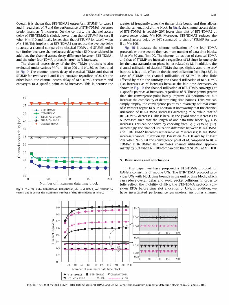
The channel access delay of the five TDMA protocols is alsoevaluated under various M from 10 to 200 and N¼50, as illustratedin Fig. 9. The channel access delay of classical TDMA and that ofSTUMP for two cases I and II are constant regardless of M. On theother hand, the channel access delay of BTB-TDMA decreases andconverges to a specific point as M increases. This is because the
Fig. 9. The CD of the BTB-TDMA1, BTB-TDMA2, classical TDMA, and STUMP for
cases I and II versus the maximum number of data time blocks at N¼50.
T N
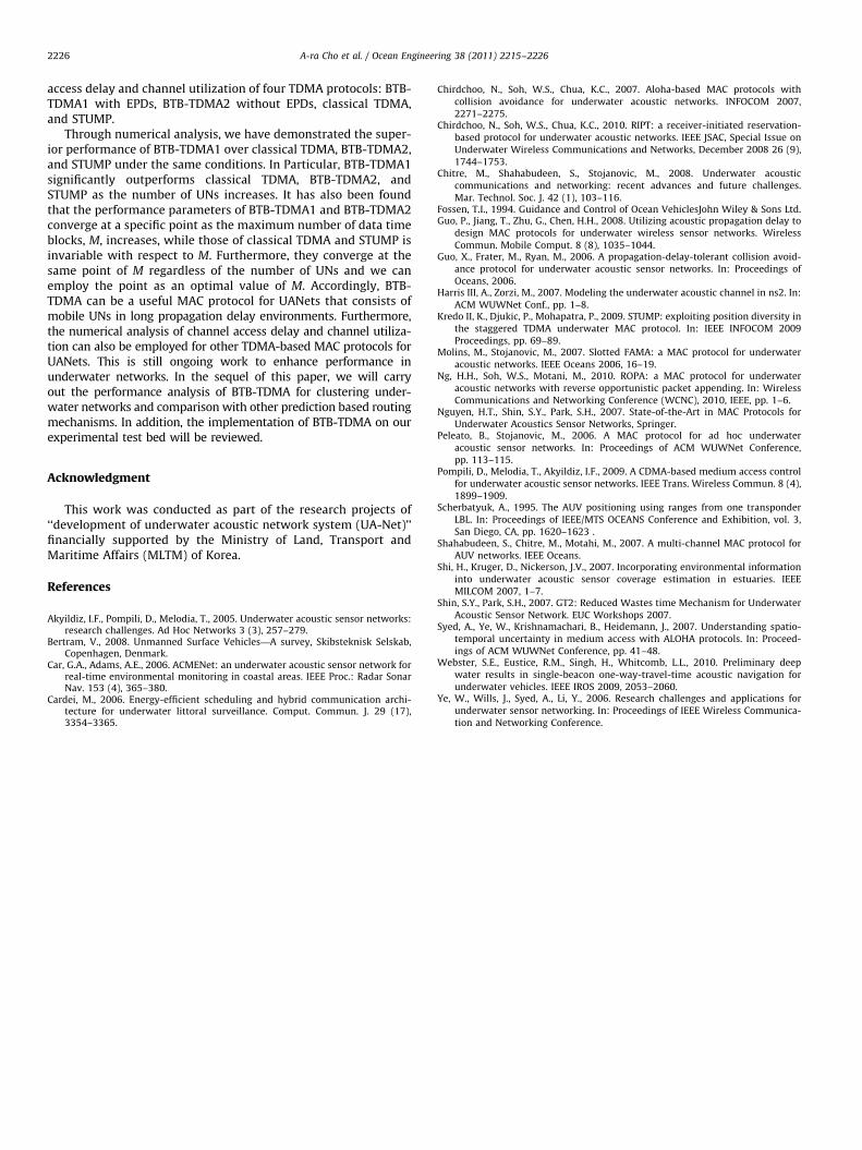
Fig. 10. The CU of the BTB-TDMA1, BTB-TDMA2, classical TDMA, and STUMP
greater M frequently gives the tighter time bound and thus allowsthe shorter length of a time block. In Fig. 9, the channel access delayof BTB-TDMA1 is roughly 20% lower than that of BTB-TDMA2 atconvergence point, M¼100. Moreover, BTB-TDMA2 reduces thechannel access delay by 14% compared to that of STUMP for caseII at M¼100.
Fig. 10 illustrates the channel utilization of the four TDMAprotocols with respect to the maximum number of data time blocks,M, at N¼50 and N¼100. The channel utilization of classical TDMAand that of STUMP are invariable regardless of M since its one cyclefor the data transmission phase is not related to M. In addition, thechannel utilization of classical TDMA changes slightly according to N
because N has little effect on the channel utilization from Eq. (38). Incase of STUMP, the channel utilization of STUMP is also littleaffected by N. On the contrary, the channel utilization of BTB-TDMAalso increases as M increases because the idle time decreases. Asshown in Fig. 10, the channel utilization of BTB-TDMA converges ata specific point as M increases, regardless of N. Those points greaterthan the convergence point barely improve CU performance, butincrease the complexity of determining time bounds. Thus, we cansimply employ the convergence point as a relatively optimal valueof M without regard to N. In addition, it noteworthy that the channelutilization of BTB-TDMA1 increases according to N, while that ofBTB-TDMA2 decreases. This is because the guard time a increases asN increases such that the length of one data time block, tb2, alsoincreases. This can be shown by checking from Eq. (12) to Eq. (17).Accordingly, the channel utilization difference between BTB-TDMA1and BTB-TDMA2 becomes remarkable as N increases; BTB-TDMA1increase channel utilization by 35% when N¼100 and by at least20% when N¼50 at the convergence point of M, compared to BTB-TDMA2. BTB-TDMA2 also increases channel utilization approxi-mately by 38% when N¼100 compared to that of STUMP at M¼100.
5. Discussions and conclusions
In this paper, we have proposed a BTB-TDMA protocol forUANets consisting of mobile UNs. The BTB-TDMA protocol pro-vides UNs with block time bounds in the unit of time block, whichcan reduce overall delay and avoid packet collisions. In order tofully reflect the mobility of UNs, the BTB-TDMA protocol con-siders EPDs before time slot allocation of UNs. In addition, wehave investigated performance parameters, including channel
N
versus the maximum number of data time blocks at N¼50 and N¼100.
A-ra Cho et al. / Ocean Engineering 38 (2011) 2215–22262226
access delay and channel utilization of four TDMA protocols: BTB-TDMA1 with EPDs, BTB-TDMA2 without EPDs, classical TDMA,and STUMP.
Through numerical analysis, we have demonstrated the super-ior performance of BTB-TDMA1 over classical TDMA, BTB-TDMA2,and STUMP under the same conditions. In Particular, BTB-TDMA1significantly outperforms classical TDMA, BTB-TDMA2, andSTUMP as the number of UNs increases. It has also been foundthat the performance parameters of BTB-TDMA1 and BTB-TDMA2converge at a specific point as the maximum number of data timeblocks, M, increases, while those of classical TDMA and STUMP isinvariable with respect to M. Furthermore, they converge at thesame point of M regardless of the number of UNs and we canemploy the point as an optimal value of M. Accordingly, BTB-TDMA can be a useful MAC protocol for UANets that consists ofmobile UNs in long propagation delay environments. Furthermore,the numerical analysis of channel access delay and channel utiliza-tion can also be employed for other TDMA-based MAC protocols forUANets. This is still ongoing work to enhance performance inunderwater networks. In the sequel of this paper, we will carryout the performance analysis of BTB-TDMA for clustering under-water networks and comparison with other prediction based routingmechanisms. In addition, the implementation of BTB-TDMA on ourexperimental test bed will be reviewed.
Acknowledgment
This work was conducted as part of the research projects of‘‘development of underwater acoustic network system (UA-Net)’’financially supported by the Ministry of Land, Transport andMaritime Affairs (MLTM) of Korea.
References
Akyildiz, I.F., Pompili, D., Melodia, T., 2005. Underwater acoustic sensor networks:research challenges. Ad Hoc Networks 3 (3), 257–279.
Bertram, V., 2008. Unmanned Surface Vehicles—A survey, Skibsteknisk Selskab,Copenhagen, Denmark.
Car, G.A., Adams, A.E., 2006. ACMENet: an underwater acoustic sensor network forreal-time environmental monitoring in coastal areas. IEEE Proc.: Radar SonarNav. 153 (4), 365–380.
Cardei, M., 2006. Energy-efficient scheduling and hybrid communication archi-tecture for underwater littoral surveillance. Comput. Commun. J. 29 (17),3354–3365.
Chirdchoo, N., Soh, W.S., Chua, K.C., 2007. Aloha-based MAC protocols withcollision avoidance for underwater acoustic networks. INFOCOM 2007,2271–2275.
Chirdchoo, N., Soh, W.S., Chua, K.C., 2010. RIPT: a receiver-initiated reservation-based protocol for underwater acoustic networks. IEEE JSAC, Special Issue onUnderwater Wireless Communications and Networks, December 2008 26 (9),1744–1753.
Chitre, M., Shahabudeen, S., Stojanovic, M., 2008. Underwater acousticcommunications and networking: recent advances and future challenges.Mar. Technol. Soc. J. 42 (1), 103–116.
Fossen, T.I., 1994. Guidance and Control of Ocean VehiclesJohn Wiley & Sons Ltd.Guo, P., Jiang, T., Zhu, G., Chen, H.H., 2008. Utilizing acoustic propagation delay to
design MAC protocols for underwater wireless sensor networks. WirelessCommun. Mobile Comput. 8 (8), 1035–1044.
Guo, X., Frater, M., Ryan, M., 2006. A propagation-delay-tolerant collision avoid-ance protocol for underwater acoustic sensor networks. In: Proceedings ofOceans, 2006.
Harris III, A., Zorzi, M., 2007. Modeling the underwater acoustic channel in ns2. In:ACM WUWNet Conf., pp. 1–8.
Kredo II, K., Djukic, P., Mohapatra, P., 2009. STUMP: exploiting position diversity inthe staggered TDMA underwater MAC protocol. In: IEEE INFOCOM 2009Proceedings, pp. 69–89.
Molins, M., Stojanovic, M., 2007. Slotted FAMA: a MAC protocol for underwateracoustic networks. IEEE Oceans 2006, 16–19.
Ng, H.H., Soh, W.S., Motani, M., 2010. ROPA: a MAC protocol for underwateracoustic networks with reverse opportunistic packet appending. In: WirelessCommunications and Networking Conference (WCNC), 2010, IEEE, pp. 1–6.
Nguyen, H.T., Shin, S.Y., Park, S.H., 2007. State-of-the-Art in MAC Protocols forUnderwater Acoustics Sensor Networks, Springer.
Peleato, B., Stojanovic, M., 2006. A MAC protocol for ad hoc underwateracoustic sensor networks. In: Proceedings of ACM WUWNet Conference,pp. 113–115.
Pompili, D., Melodia, T., Akyildiz, I.F., 2009. A CDMA-based medium access controlfor underwater acoustic sensor networks. IEEE Trans. Wireless Commun. 8 (4),1899–1909.
Scherbatyuk, A., 1995. The AUV positioning using ranges from one transponderLBL. In: Proceedings of IEEE/MTS OCEANS Conference and Exhibition, vol. 3,San Diego, CA, pp. 1620–1623 .
Shahabudeen, S., Chitre, M., Motahi, M., 2007. A multi-channel MAC protocol forAUV networks. IEEE Oceans.
Shi, H., Kruger, D., Nickerson, J.V., 2007. Incorporating environmental informationinto underwater acoustic sensor coverage estimation in estuaries. IEEEMILCOM 2007, 1–7.
Shin, S.Y., Park, S.H., 2007. GT2: Reduced Wastes time Mechanism for UnderwaterAcoustic Sensor Network. EUC Workshops 2007.
Syed, A., Ye, W., Krishnamachari, B., Heidemann, J., 2007. Understanding spatio-temporal uncertainty in medium access with ALOHA protocols. In: Proceed-ings of ACM WUWNet Conference, pp. 41–48.
Webster, S.E., Eustice, R.M., Singh, H., Whitcomb, L.L., 2010. Preliminary deepwater results in single-beacon one-way-travel-time acoustic navigation forunderwater vehicles. IEEE IROS 2009, 2053–2060.
Ye, W., Wills, J., Syed, A., Li, Y., 2006. Research challenges and applications forunderwater sensor networking. In: Proceedings of IEEE Wireless Communica-tion and Networking Conference.