design of a datalogger for modbus -...
TRANSCRIPT

Design of a Datalogger for MODBUS
CENTRE FOR ENERGY AND THE ENVIRONMENT
Software Document 39
February 2018

2
Report Name: Design of a Datalogger for MODBUS
Author(s): T.A. Mitchell
Report Number: Software Document 39
Publication Date: February 2018
CENTRE FOR ENERGY AND THE ENVIRONMENT
UNIVERSITY OF EXETER, HOPE HALL,
PRINCE OF WALES ROAD, EXETER, EX4 4PL
T: 01392 724143 W: www.exeter.ac.uk/cee
Rev. No. Comments Approved By Date 1 Final Draft D Lash 28/2/18
3
CONTENTS
Management Summary ............................................................................................................................. 4
1. Introduction .......................................................................................................................................... 5
1.1 Methods of Periodically Logging Meter Data ................................................................................ 5
1.2 The MODBUS RTU Protocol ....................................................................................................... 5
1.3 Approach to Hardware ................................................................................................................... 6
1.4 Approach to Software ..................................................................................................................... 6
2. Hardware ............................................................................................................................................... 6
2.1 Recommendations for Future Devices .......................................................................................... 8
3. Software ................................................................................................................................................. 9
3.1 Header............................................................................................................................................. 9
3.1.1 Libraries ................................................................................................................................... 9
3.1.2 Definitions and Global Variable Declaration ...................................................................... 10
3.2 Setup ............................................................................................................................................. 10
3.3 Main Loop .................................................................................................................................... 11
3.4 Other Functions ........................................................................................................................... 11
3.4.1 Interval Check ....................................................................................................................... 11
3.4.2 Read LCD Buttons ............................................................................................................... 11
3.4.3 Blink LED.............................................................................................................................. 11
3.4.4 Find Next ............................................................................................................................... 11
3.4.5 Date Time .............................................................................................................................. 11
3.5 Recommendations for Future Improvements ............................................................................. 12
4. User Guide .......................................................................................................................................... 12
APPENDIX 1 Component Listing ........................................................................................................ 17
APPENDIX 2 Pin Usage ....................................................................................................................... 18
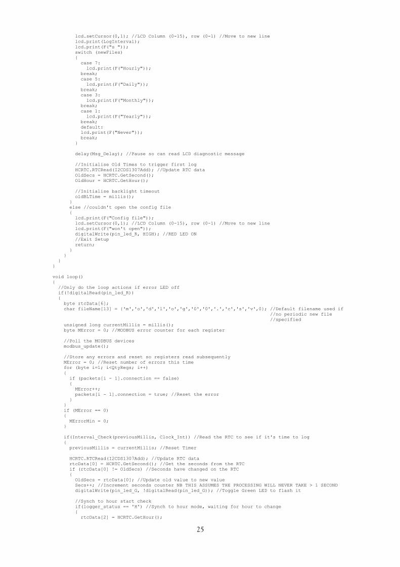
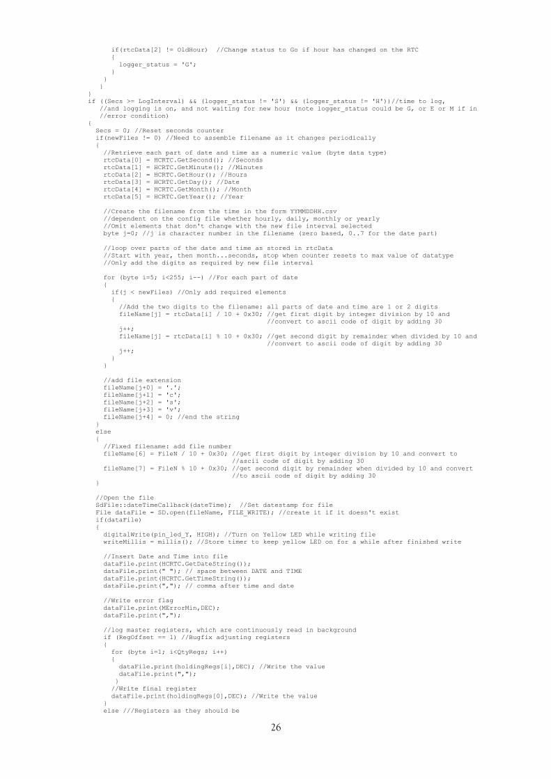
APPENDIX 3 Code Listing ................................................................................................................... 19
APPENDIX 4 Code Version History .................................................................................................... 31
APPENDIX 5 Testing of Communications Parameters ....................................................................... 31
APPENDIX 6 Example Configuration File .......................................................................................... 32

4
MANAGEMENT SUMMARY
Periodic recording of meter readings at time intervals of 30 minutes or less is valuable to reveal patterns of energy consumption and is essential for many monitoring tasks. Historically, this has been achieved by counting events, such as rotations of a spinning disc, flashes of visual indicators or closure of contacts on a pulse output. Whilst effective, none of these methods record the actual meter reading and if recording is interrupted the total consumption is not known unless meter readings are noted at the start and end of the period. Furthermore, some meters are only equipped with a digital output that cannot be recorded in this way.
A digital output typically makes all of the information (registers) on the meter available at any time when requested by a command from a connected device. Most typically the device is a building management system. Available registers on an electric meter may include total consumption, rate of consumption, voltage, current, supply frequency, power factor and harmonics values. Another type of meter where digital outputs are commonly provided are heat meters, with total flow, flow rate and flow and return temperatures being available. One common form of digital output is MODBUS-RTU, with communication over a screened twisted pair over up to 1 km between up to 32 devices.
To communicate over MODBUS-RTU, one device acts as a master and requests information and the other devices are slaves and respond to these requests. The master can be a microcontroller (e.g. the building management system or a bespoke deice), or a PC running suitable software. This report describes a bespoke master device designed specifically to periodically record values from slave devices.
The design is based around an Arduino Nano microcontroller, equipped with a memory card interface, battery-backed real-time clock, liquid crystal display, pushbuttons and RS-485 communications interface. Software has been written to record up to ten registers defined by the user at intervals of between one second and 18 hours, and features options to synchronise recording to whole hours, start and stop recording on a button press, record either to a single file or create new files hourly, daily, monthly, annually or on a button press, and to enable or disable the stop button.

5
1. INTRODUCTION
This document describes a datalogger that can be used to periodically request and store values from a meter equipped with a MODBUS RTU digital interface. It covers both the design of the datalogger (hardware in Section 2 and software in Section 3) and use (in Section 4).
1.1 METHODS OF PERIODICALLY LOGGING METER DATA
Projects monitoring energy usage or system performance frequently require the periodic logging of values from meters. This can be achieved in a number of ways:
1. connecting a pulse counting datalogger to a pulse output provided on the meter, each contact closure between the terminals representing a stated amount of consumption;
2. counting other periodic indicators, such as an LED on the meter that flashes after a stated amount of consumption, revolutions of a spinning disk on a mechanical electricity meter, or detecting the silvered digit on the mechanical numeric register of a meter, or
3. polling the meter for a reading via a digital interface.
The Centre for Energy and the Environment (CEE) has historically used methods 1 and 2. These have the advantage of being relatively simple to implement, but the disadvantage that if the logging is interrupted (e.g. due to interruption of the datalogger power, or a cable fault between the datalogger and meter) it can be difficult or impossible to determine the increment of the meter in the interim period. Method 3 is more difficult to implement, but has the advantage of obtaining a reading that directly matches the visual display on the meter.
1.2 THE MODBUS RTU PROTOCOL
Digital interfaces are most common on electricity and heat meters, and may be provided as standard, as a factory-fitted option or plug-in retro-fittable module. A number of communications protocols are in common use, based on differing physical interfaces and command sets. MODBUS1 RTU is a commonly used and long-established protocol used by building management systems (BMS). 2-wire RS485 is commonly used as the interface, this is a serial interface over a shielded twisted pair. The data signal is differential across the pair of data lines, i.e. one carries the inverse of the other. When the signal is read, any interference induced in the cable is largely cancelled out, permitting long cable runs of up to 1 km. Each network supports up to 32 devices connected in parallel across the data pair, and a 120Ω resistor across the data pair at the first and last device supresses cable end signal reflections. The connections are commonly labelled data – (or A), data + (or B) and ground (or C), although some manufacturers reverse the polarity of A and B—a source of confusion.
Since only a single data signal is carried, the data is half-duplex, i.e. at any one time data is either being sent or received by a device on the network. There is a possibility of data collision (resulting in data corruption) if one device is transmitting while another is receiving. This is overcome in the MODBUS communications protocol in a number of ways:
1. One device is designated the master and the rest as slaves; the master polls slaves for data and awaits a response.
2. Each device is assigned a slave ID, and a message from a master will be addressed to a specific slave device using this ID2. Other slaves will ignore the command.
3. A MODBUS message (either a command from the master or response from a slave) includes a 2-byte cyclical redundancy check (CRC) which is calculated from the content of the rest of the
1 MODBUS is named after the company that invented it, Modicon (later absorbed into Schneider Electric). 2 It is possible to “broadcast” a message to all devices by setting the Slave ID in the command to 0.
6
message, the receiving device uses this to check for data corruption. A slave will return an error code if the CRC is invalid (or if the content of the message is otherwise invalid, e.g. the value of a non-existent register is requested).
4. Furthermore, an odd or even parity check bit can be included in the communications protocol, the value of this bit is calculated from the 8 bits of data to make the overall sum of bits either odd or even.
5. The master will typically be set to resend the request up to set number of times if an invalid response, or no response, is received.
1.3 APPROACH TO HARDWARE
The MODBUS master can be, for example, a BMS outstation, a PC running software3 and equipped with an RS485 interface (converters from USB and RS232 are readily available), or a bespoke device.
The creation of a bespoke MODBUS datalogging device will require a microcontroller chip to be programmed with suitable code and connected to an RS485 interface and peripherals such as a real-time clock (RTC), memory card interface and (optionally) a user interface such as a keypad and
display. The design described here is based around an Arduino, a relatively user-friendly microcontroller aimed at prototyping and the hobbyist / experimentation market.
1.4 APPROACH TO SOFTWARE
The Arduino has limited program and data memory, so it would be difficult to write a sufficiently elaborate yet compact menu system to fully configure the datalogger. Therefore setup parameters are read from a file on the memory card. Data are logged to the card. The display indicates the current status of the datalogger, including error messages, setup parameters, and during datalogging the file being logged to, the current time, logger status, and the value of one of the registers specified to be logged. The user interface allows the logger to be stopped and started, the data filename incremented, the register displayed on the LCD to be selected, the backlight controlled and the datalogger to be reset.
Functions thought to be most useful for typical datalogging tasks have been included, such as synchronisation of logging intervals to a whole hour, start on button press, disabling the stop button and the periodic creation of new datafiles.
2. HARDWARE
Traditionally, microcontroller chips such as the PIC family were programmed by writing code directly in binary or hexadecimal. Assembly language was introduced as a more user-friendly alternative, but (for the PIC) still has a very small instruction set (35 commands) and is difficult to work with. Compilers are now available that allow programs to be written in dialects of Basic or C. The hardware side has also become more user-friendly, with pre-built circuit boards now available aimed at the hobbyist and others without a background in electronics engineering. The circuit includes the microcontroller chip, ancillaries such as a communications interface, clock, power circuit etc., and are supported by software to compile code and upload it to the chip.
These pre-built circuit boards range from simple microcontrollers to relatively powerful embedded computers. A microcontroller is generally limited to executing some initialisation code, then endlessly cycling round a loop. An embedded computer is far more suited to ad-hoc execution of
3 Simply Modbus Master (http://www.simplymodbus.ca/RTUmaster.htm) is a useful PC-based software tool for MODBUS RTU communication from a PC.

7
tasks as requested by the user. The Arduino and BeagleBoard are examples of microcontrollers (both
are open-source designs), and the Raspberry Pi is an example of an embedded computer.
The design described here is based around an Arduino Nano, one of a number of devices in the Arduino family:
1. Arduino Uno: 16 MHz clock speed, 32 kB program memory, 2 kB data memory, 14 digital inputs / outputs, 6 analogue inputs. Generally connections are provided with sockets for the
installation of stackable peripheral boards (shields), or jumper wires. Irregular pin spacing4 makes it difficult to mount on a standard breadboard or stripboard PCB.
2. Arduino Nano: Similar to the Uno (2 additional analogue inputs), but reduced in size, and with connections provided via solder connection or header pins. Regular pin spacing enables mounting on standard stripboard, but few pre-built shields are available.
3. Arduino Leonardo, Mega 2560: these are two examples of devices with increased memory and an increased number of inputs and outputs.
The Arduino Nano is adequate for the task of logging a small number of registers to a memory card, but the limited program and data memory places constraints on the extent to which an elaborate user interface can be provided, and the number of registers that can be logged (due to the buffer required for the incoming data, to only about ten). The design uses the following components (further details are provided in Appendix 1): -
1. Arduino Nano: The Arduino is an open-source design and the product used is a clone. It uses the CH340G USB driver chip, which differs from an original Arduino and requires a suitable driver to be installed5.
2. RS485 to TTL adaptor: Converts between the RS485 serial interface required for MODBUS and
the TTL (5 V) serial interface on the Arduino. A further digital pin is required to switch between transmit and receive mode6. The RS485 interface is brought out on a male 9-pin D connector (pin 1: data +, pin 2: data -, pin 5 ground, pin 6 +5 V, pin 9 power supply positive).
3. Real-Time Clock (RTC): Whilst the Arduino provides timer functions, for a datalogger a reliable real-time clock that will maintain timekeeping even if the device is reset or loses power is required. The RTC circuit incorporates a CR1220 backup battery and connects to the I2C port
on the Arduino7. 4. SD Card interface: The limited memory on the Arduino is insufficient to store logged data, and
data would be lost if the device was powered down. The SD card interface enables an SD card to be used for storage, the card can subsequently be removed and the file copied to a PC. Configuration settings for the logger are read from a file on the card. The card interface
connects to the SPI interface on the Arduino. 5. LCD Screen: A display screen is useful both for debugging during development (as the connection
to the RS485 interface uses the same serial port as the Arduino’s USB port which could otherwise be used for debugging), and also to provide confirmation messages and information to the user. The LCD screen used is a 16 x 2 character display (Hitachi HD44780) in the form of a shield designed for an Arduino Uno, and occupies seven digital pins on the Arduino.
4 Claimed to be a design mistake. 5 CHG_SEP_2017.zip, available from rebrand.ly/b35d (last accessed 26/2/2018). 6 The RS485 module DE pin is set high to transmit and the RE pin is set low to receive. These can be tied together and used to select either transmit or receive in the simple interface required. 7 A further unused pin provides a square wave reference. The device also contains 56 bytes of flash memory storage, which is not used.

8
6. Pushbuttons: The LCD screen PCB incorporates five user programmable pushbuttons (arranged as
Up, Down, Left, Right and Select), plus a reset button which duplicates that on the Arduino. The user-programmable pushbuttons are wired to a single analogue input, and each button places a known resistance between the analogue pin and 5 Volts, giving a reading in the range 0 to 1023 on the input.
7. Indicator LEDs: Red, yellow and green LEDs are provided as status indicators.
In addition, the Arduino Nano requires a DC power supply between 7 and 12 Volts, this can be connected via the 2.1 mm power socket (centre pin positive) or between pin 9 (positive) and pin 5 (negative) on the 9-pin D connector. Power could be sourced from a mains adaptor or suitable battery pack. The mini USB socket on the Arduino is accessible to allow easy reprogramming of the unit.
The datalogger (uncased and cased) is illustrated in Figure 2.1 and Figure 2.2.
Figure 2.1. Components of the datalogger.
Figure 2.2. The completed datalogger reading the kW h register of a connected meter.
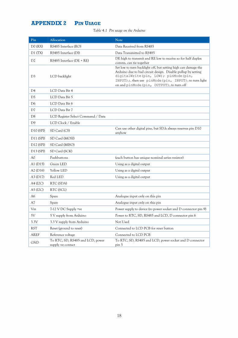
Connections to each component are described in Appendix 2.
2.1 RECOMMENDATIONS FOR FUTURE DEVICES
The datalogger is to an extent a prototype, and the following recommendations are made for future builds:

9
1. A bare display (with serial interface but without Arduino Uno shield) would be more suitable, being easier to mount in a case and allowing an I2C adaptor board to be used, freeing up six digital input/output pins (the code would need to be adapted to toggle communication between the RTC and display, and a suitable voltage provided to the contrast pin of the LCD circuit board via a fixed or variable resistance).
2. Panel mounted pushbuttons would be easier to work with and tidier than trying to actuate the circuit-board mounted buttons provided on the LCD shield from the outside of the case.
3. An Arduino Nano datalogging shield is available8 incorporating both an RTC and a micro SD card socket. This would simplify construction, but a full-size SD card is slightly preferable since most laptop computers only take a full-sized card and an adaptor is required to read a micro SD card.
3. SOFTWARE
The software was developed in the Windows Arduino programming environment, which provides a rudimentary library manager, compile-time debugging messages and facilities for uploading code to
the Arduino and receiving diagnostic output written by the Arduino to the serial port during program execution9.
Each section of the program is described below. A program listing is provided in Appendix 3. A version history is given in Appendix 4.
3.1 HEADER
This section includes references to libraries and global variable declarations
3.1.1 LIBRARIES
Publicly available libraries were used to accomplish “low level” tasks without reinventing the wheel:
LiquidCrystal.h Standard Arduino library for 4-bit serial communications with multi-character liquid crystal displays;
SPI.h Standard Arduino library for communications on the SPI port (used by the SD card);
SD.h Standard Arduino library for reading and writing from and to an SD card; Wire.h Standard Arduino library for communications on the I2C port (used by the RTC);
HCRTC.h10 Contributed library for reading and setting the RTC; SimpleModbusMaster.h 11 (from SimpleModbusMasterV2rev2.zip) Contributed library for
MODBUS communications over RS485 on the standard hardware serial port.
Documentation of some libraries is poor and compatibility with pre-built circuits (which are frequently supplied with no documentation is to some extent a matter of trial-and-error). Several alternative libraries were tested for both the RTC and MODBUS functions before one was identified that appeared to be stable. An issue remains with the MODBUS library that communications fails with some baud and parity setting combinations, and data are misplaced in the holding array for other combinations. However, most other MODBUS libraries only supported a data bit / parity
8 Deek Robot Nano Datalogging Shield, product ID 8105. 9 This form of output is useful for debugging, but not possible on the datalogger as the RS485 interface uses the same communications port (digital pins 0 and 1) as the USB / Serial port. 10 Real Time Clock RTC library. https://github.com/dtu-mekatronik/HCRTC, last accessed 26/2/2018. 11 charlesbaynham/simple-modbus https://github.com/charlesbaynham/simple-modbus, last accessed 26/2/2018 (latest version will be available at https://drive.google.com/drive/folders/0B0B286tJkafVYnBhNGo4N3poQ2c ).

10
combination (8 data bits, no parity bit, one stop bit) which is the default for RS232 communications but breaches the MODBUS standard and is not available on most metering devices12.
3.1.2 DEFINITIONS AND GLOBAL VARIABLE DECLARATION
One way of specifying what is effectively a global constant is to use the #define construct. This simply specifies a name and a string that the compiler replaces any instances of name with at compile
time. Given the very limited data memory on the Arduino, this is advantageous as the information is them held in program memory rather than data memory.
Global variables are declared, i.e. those which may need to be accessed during both setup and the main program loop. These include the arrays required for MODBUS communications to store details of the registers to be read and the values returned.
The LCD and RTC libraries are also initialised.
3.2 SETUP
setup() is a standard Arduino function that runs once following the processing of any header information. For the datalogger, it includes the following:
1. Declaration of local variables only used within the setup function, mainly to receive data read from the configuration file and to set the RTC.
2. Set the size of the LCD (number of characters per row and number of rows), initialise the LCD backlight13, initialise digital pins driving the LEDs, initialise the RS485, SD card and RTC interfaces.
3. Attempt to read the configuration file modlog.cfg from the SD card. Return an error if the card cannot be read. If the file is missing, create an example file for the user to edit and do not proceed further.
4. Read parameters from the configuration file into variables. These include an option to set the clock, communications baud rate, parity and stop bit settings, datalogger parameters (logging rate, new file creation options, initial state, whether the stop button is available, and details of the MODBUS registers to be logged). Note error checking is minimal; this could cause unexpected behaviour if numerical values in the file are out of range. Invalid single character values default to the first option listed in the example file (don’t set clock, odd parity bit, one stop bit, don’t create new files depending on date and time, start logging immediately, disable stop button).
5. If the option to set the clock was specified in the configuration file, a prompt is displayed on the LCD and the clock is reset when a button is pressed.
6. If the clock set, synchronise logging to a full hour (first time only) or start on button press (first time only) options were specified, modify the configuration file so these options are not implemented on subsequent resets.
7. Display an information message confirming the baud rate, parity, stop bit, logging rate and new file creation options.
8. Initialise timers used to read the RTC and control the backlight.
12 Such a breach would not be problematic if only using MODBUS communications internally between several Arduinos, for example. 13 Poor circuit design is reputed to potentially damage the digital output used to control the backlight if used as documented (setting the output low or high). A workaround is to first set the pin in the low state as an output, then declare the pin as an output to turn the light off, or an input to turn it on.
11
3.3 MAIN LOOP
loop() is a standard Arduino function that runs continuously as a loop once the setup() function has been completed. For the datalogger, it includes:
1. Check the state of the red LED and only process the remaining contents of loop() if the LED is off (which implies the configuration file was successfully read).
2. Declare local variables used to hold RTC data, data filename, logging interval counter and error flag for MODBUS communications.
3. Poll the MODBUS devices by calling a library function. Check whether an error condition resulted.
4. Read the RTC. Note if the seconds have incremented, this will be used to trigger logging on the specified interval. Note if the hours have incremented, and start logging if they have and the option to start on the hour is specified.
5. If the datalogger is in the “Go” state and the seconds have incremented by at least the logging interval, read the RTC, determine the data filename, and write data to the file. Reset the communications error variable.
6. Reset card write or MODBUS error conditions if they have cleared since being triggered. 7. Periodically (every 900 ms) update the LCD. 8. Read the value of the analogue input connected to the buttons and take appropriate action. 9. Check backlight timer against current timeout and switch backlight off if required.
3.4 OTHER FUNCTIONS
These are functions that are called from the setup() or loop() functions.
3.4.1 INTERVAL CHECK
Accepts a time datum and interval, compares to the current timer value (milliseconds since board booted up, as an unsigned long value), and returns 1 if the interval has been exceeded or zero otherwise. Accounts for the case where the timer has exceeded 65,535 and restarted counting from zero.
3.4.2 READ LCD BUTTONS
Checks a minimum interval (500 ms) has elapsed since a button press last triggered actions, this stops multiple actions due to the button being held down longer than it takes to increment around the loop() function once. If this condition is met, set a variable indicating which button was pressed, and reset the LCD backlight timer.
3.4.3 BLINK LED
Blinks the specified LED a set number of times. Currently only used to flash the red LED when the clock is set. Note: uses delay() function which can detrimentally affect code performance were the function called from within loop().
3.4.4 FIND NEXT
Accepts a reference to an open file and the ASCII code of a character to search for. Returns the next instance of this character forward from the current position in the file. Used to skip over comments when reading the configuration file.
3.4.5 DATE TIME
By default, when new files are written to the SD card, the datestamp is set to 1/1/2000 01:00. Modified files retain their previous datestamp. To set the datestamp correctly, this function is called

12
to set the datestamp to the current value of the RTC. Note: if the configuration file is altered by the program, the datestamp is not updated so it still indicates when the file was last edited by the user.
3.5 RECOMMENDATIONS FOR FUTURE IMPROVEMENTS
Issues not fully resolved or implemented include:
1. Certain combinations of baud rate and parity setting result in either no data being returned by MODBUS communications, or the data to be offset by one in the holding array (see Appendix 5). The latter has been adjusted for in code. At present no MODBUS master library has been identified that overcomes this problem. They all appear to use a relatively crude communications timing mechanism that may mot remain robust for all different permutations of communications settings.
2. A lack of exhaustive error checking (for invalid values entered by the user) when reading the configuration file. This could significantly complicate reading data from the file.
3. Error detection for MODBUS communications errors and SD card write errors is not reliable. For MODBUS, this could possibly be improved by interrogating other diagnostic values returned by the function. For the SD card it is a consequence of write caching and would require the use of a more low level and complicated SD card library.
4. No checking for a full SD card. Again this would only be possible using a more low level and complicated SD card library.
4. USER GUIDE
1. Prepare the MODBUS network: Use shielded twisted pair cable to connect together all the MODBUS devices, starting from the datalogger and linking each device in turn. Connect all the + (or B) terminals with one wire (connect to pin 1 of the 9-pin D connector on the datalogger), connect all the – (or A) terminals with the other wire (connect to pin 2 of the 9-pin D connector on the datalogger), and connect all the ground terminals to the screen of the cable (and connect to pin 5 of the 9-pin D connector on the datalogger). Note: some devices transpose A and B; if a device does not respond try swapping the connections on that particular device. On the last device connect a 120Ω resistor between the + and – (B and A) terminals on the device at the end of the line.
2. Configure the MODBUS devices: Set a unique slave ID (address) on each slave device, in the range 1 to 247 (up to 255 is possible, but does not adhere to the MODBUS standard). Set the baud rate, parity and stop bits on each device to a common value. 9600 baud and odd parity is recommended14. Valid baud rates are 300, 600, 1200, 2400, 4800, 9600, 14400, 19200, 28800, 38400, 57600, or 115200. Valid parity and stop bit settings are an odd or even parity check bit and one stop bit, or no parity check bit and 2 stop bits (no parity bit and one stop bit is supported, but does not adhere to the MODBUS standard). On MODBUS devices with a screen and menus, these settings are normally made via the menu system. Simpler devices may use switches or links to set the parameters, or require them to be set them by sending data to the device from a PC.
3. Arrange power supply to datalogger: The datalogger may be powered in one of three ways: a. Via the 2.1 mm DC power socket. Requires a regulated DC supply of between 7 and
12 Volts, centre pin of connector positive.
14Baud rates of 19,200 and 115,200, or even or no parity should be avoided as a bugfix has been implemented to overcome mis-ordered data for these settings. Baud rates of 1,200, 2,400 or 4,800 with even or no parity have been found to return no data. Two stop bits with a parity bit, or one stop bit and no parity bits have not been tested at all. See Appendix 5 for summary.

13
b. Via pin 9 (positive) and pin 5 (negative) of the 9 pin D connector. Requires a regulated DC supply of between 7 and 12 Volts. This may be more physically secure than the power connector.
c. Via a USB cable and power supply. This may, however, come unplugged relatively easily. Power via the USB can be supplied at the same time as either method b or c below without ill effect. Devices such as computers are not recommended as a power source since they may attempt to communicate with the datalogger, leading to corruption or unexpected behaviour.
4. Prepare a configuration file for the datalogger: Settings are read from the text file modlog.cfg on the SD card. To create an example file (reproduced in Appendix 6), place an SD card that does not contain a file of this name in the datalogger and connect power to the datalogger. The
datalogger screen shows the message Config file not found, created, and the red LED lights. Remove the card and edit the file on a PC. Note: the position of items is critical, in particular the colons, spaces and carriage returns15. Text before the colons on each line is not read.
The first line in the file is Update Time (N/Y): Setting to Y enables the real-time clock
on the datalogger to be set when the logger is started. Set to N (also the default for any other character) if the clock is already correct (check this by starting the datalogger with an SD card inserted containing a valid modlog.cfg file). Note: the clock is only set the first time the file is read (when the datalogger is powered on or reset); the file is then modified so that the clock is not set if the datalogger is subsequently reset or power is lost and restored.
The second line is New Time (YYMMDDHHMMSS): This is the date and time that will be set if the option to set the clock is specified, starting with the two last digits of the year, then two digits indicating the month and so on for day, hour, minute and seconds. Set it a little while into the future, you will be prompted to press a button to set the clock to this value when the datalogger is started. If the clock is not being set, this line must still be included in the file, but the value is ignored.
The next line specifies the baud rate, set to one of the values listed in step 2 above.
The next line specifies the type of parity bit (N for none, O for odd or E for even). Any other character is interpreted as odd parity.
The next line specifies the number of stop bits (1 or 2). Any other character is interpreted as one stop bit.
The next line sets the logging rate in seconds. This can be set as an integer between 1 and 65,535.
The next line specifies how frequently a new datafile is created (H for hourly, D for daily, M for
Monthly, Y for yearly or N for Never; other values are interpreted as N.). Logging into a series of smaller files reduces the risk of corruption and data loss, but can make the data more difficult to work with. A new file is created every time the element of the date or time specifies changes to a new value, i.e. on every new hour, day, month or year. The filename is in the form YYMMDDHH.csv where YY is the year, MM the month, DD the date and HH the hour (only
15 If the file is altered, it may not be read properly and lead to unpredictable behaviour of the datalogger. One possible indicator of this is garbled characters in the confirmation message displayed at step 5d.

14
elements that will increment between files are included, for example if a new file is created
monthly, the filename is of the form YYMM.csv).
The next line specifies the starting file number as two numeric digits. This line must be
present, but the value is only used if the new file rate is set to N. Data are then logged to a file
named modlogXX.csv, where XX is the file number. This number can be incremented during logging to create a new file (useful if, for example, conducting an experiment and saving data for each scenario into a different file). To ensure all data are logged to a single file that cannot be changed set the file number to 99.
Note: Existing files are not overwritten, if a file already exists data are appended to the end of the file.
The next line sets the initial state of the datalogger when started or reset. Valid values are:
G – Start logging as soon as possible (also the default for any unlisted character);
S – Enter the Stop condition and only start when the Go/Stop button is pressed (persistent, after a reset or power off/on the datalogger will again enter the stop condition);
s - Enter the Stop condition and only start when the Go/Stop button is pressed (non-persistent, file is modified when read so that after a reset or power off/on logging will restart as soon as possible);
H – Synchronise to hour, logging only starts when the hour changes to a new value (persistent, after a reset or power off/on the datalogger will only restart logging when the hour changes). This is useful to ensure that timestamps have round values, but has the disadvantage that a gap in data of up to an hour may result if the logger is reset or after power is restored following an outage. The option works best if the logging rate is a factor of 3,600.
h – as H, but non-persistent (after a reset or power outage, logging resumes as soon as possible and is no longer aligned to a full hour).
The next option sets whether the Go/Stop button can be used to stop the datalogger (Y for yes
or N for no; other values are interpreted as N).
The next line is a header for the rest of the file, where the MODBUS registers to log are specified (up to ten registers may be recorded). Each line below this contains the slave ID (1-
255), register type (C for read coil status (function 1), S for read input status (function 2), I for
read input register (function 4) or H for read holding register (function 3)), and register number (0 – 65535). Each parameter is separated by a comma and the values for each register are on a new line. Note that the register numbers are zero-based, whereas some documentation states the registers starting at one so one must be subtracted from the number. Some documentation states register numbers in hexadecimal, the values must be converted to decimal. Some slave devices infer the register type from the register number, or the register type from the register number, so some experimentation may be necessary if the device does not respond as expected. Starting registers are 0 for read coil status, 10,000 for read input status, 30,000 for read input register or 40,000 for read holding register, so for example a device that infers the register number from the register type may require the register number to be set to 5,000 rather than 45,000 when reading holding register 45,000.

15
5. Switch the datalogger on: Insert the SD card prepared in step 4 and provide power as in step 3. The datalogger is initialised as follows:
a. The SD card is checked. If the SD card cannot be read, an error message SD Card
Error is displayed and the red LED lights. Datalogging is not possible. Check that the card is formatted as FAT16 or FAT32.
b. The modlog.cfg file is read. If the file is not found but an example file could be written, the
error message Config file not found, created is displayed. If the file is
not found and an example file could not be written, the error message Config file
not found, failed is displayed. If the file is present but could not be read, the
error message Config file won’t open is displayed. In any of these cases the red LED lights and datalogging is not possible.
c. If the option to set the clock was specified in the modlog.cfg file, the message Press
Go/Stop to set clock is displayed. Wait until the current time is that specified in the file, then press the Go/Stop button momentarily. The red LED flashes once and
a confirmation message is shown briefly: Clock set to DD/MM HH:MM:SS (showing the date and time).
d. A message confirming the communications and logging parameters is briefly displayed, in the form
Baud, Data Bits Parity Stop Bits
Logging Interval New File Interval
6. The datalogger enters its normal running mode. The display shows the following:
Day/File Time Status Item
Sl.ID Register Value
where the entries are as follows:
Day/File displays the day of the month if the option to create a new datafile periodically was specified or if the current file number is the maximum permissible (99). Otherwise, the current file number is displayed (00 to 98).
Time displays the current time (in the form HH:MM:SS).
displays an* if the backlight timeout is one hour; if it is the default 30 s * is not displayed.
Status is S if the logger is stopped, G if the logger is running, H if waiting to start (synch to hour active), E if there was an error writing to file (logging will resume if possible), or M if a complete set of values could not be read from the MODBUS devices during the previous logging interval.
Item is the item number (1 to 10) of a register specified in the input file. By default item 1 is displayed.
Sl.ID is the slave ID for the item number being displayed on screen.
Register is the register type for the item number being displayed on screen (C for read coil status, S for read input status, I for read input register or H for read holding register), followed by the register number (zero based) for the item number being displayed on screen.
Value is the last value read for the for the item number being displayed on screen (will update about every second, regardless of the logging interval).

16
The green LED will flash during normal running mode. The yellow LED will flash when a value is being written to the SD card. If an error condition develops with the SD card or MODBUS communications, the yellow LED will stay illuminated (due to caching of writing to the card, this error indication and the associated E status indicator may not be triggered for some time, even if the SD card is corrupt or removed; the MODBUS error checking is also not exhaustive).
7. The pushbuttons provide the following functions while the datalogger is running:
Go/Stop: If the datalogger is in the stop condition (S displayed) or synch to hour (waiting to start (H displayed), press this button momentarily to start logging immediately. If the datalogger is in the go condition (G, E or M displayed), press to stop logging (unless this option was disabled in the configuration file).
: The display backlight stays on for 30 s after normal running mode starts. It comes back on for 30 s after any button is pressed. Press this button to toggle between this default 30 s timeout and a 1 hour timeout (useful if you need to monitor values on the screen over an extended period). The contrast of the display can be adjusted by turning the screw to the left of LCD Contrast.
Item +, Item –: Press to change the item number displayed on screen (if more than one register was specified in the configuration file).
File: If the option to log to a single file was specified, press this button to increment the file number by one (the file number is shown at the top left of the screen, until it reaches the maximum permissible value of 99, when it is replaced by the day of the month and the File button will have no effect).
Reset: Resets the datalogger (returning to step 5). Previously logged data are retained.
8. To retrieve data, either power down the datalogger or (if available) press the Go/Stop button to stop datalogging. Remove the SD card and copy the files to a PC. Data written on each timestamp take the form:
14/02/18 10:00:09,0,34069,2348,7,5020
(Date Time, Error Flag, followed by register values separated by commas).
If Error Flag is 1, it indicates that a complete set of readings was not retrieved during this interval and one or more of the readings are those read previously.

17
APPENDIX 1 COMPONENT LISTING
Item Detail Source Approximate Cost
Arduino Nano Arduino Nano v3.0 (ATMEGA 328P) CH340G
eBay (scooterboy101) £2.75
RS485 Adaptor RS485 Serial Port Adapter Module TTL RS-485
eBay (abaxas_uk) £1.95
Real Time Clock DS1307 I2C RTC Real Time Clock Module
eBay (jlb_electrical) £2.75
SD Card Interface Arduino compatible SD Card Module
eBay (hobbycomponents) £2.99
LCD Shield Blue 16x2 (1602 / HD44780) LCD Screen Keypad Shield
eBay (puretekuk) £4.95
Stripboard 36 strips x 62 rows Onecall PC01298 £6.66
LEDs 5 mm, Red, Yellow, Green Onecall SC08044, SC08046, SC08048
£0.24
Series Resistors 470 Ω ¼ W Onecall RE03756 £0.06 D Connector 9 pin male solder bucket Onecall CN00799 £0.72 Jackposts 10 mm length Onecall CN06421 £0.50 Power Socket 2.1 mm DC Power Socket Onecall AV15144 £0.45 Enclosure 120 x 65 x 40mm ABS Onecall EN55081 £2.93 Battery GP CR1220 Onecall BT00874 £0.67 Total £27.62
18
APPENDIX 2 PIN USAGE
Table 4.1 Pin usage on the Arduino
Pin Allocation Note
D0 (RX) RS485 Interface (RO) Data Received from RS485
D1 (TX) RS485 Interface (DI) Data Transmitted to RS485
D2 RS485 Interface (DE + RE) DE high to transmit and RE low to receive so for half duplex comms, can tie together
D3 LCD backlight
Set low to turn backlight off, but setting high can damage the Arduino due to bad circuit design. Disable pullup by setting digitalWrite(pin, LOW); pinMode(pin,
INPUT);, then use pinMode(pin, INPUT); to turn light on and pinMode(pin, OUTPUT); to turn off
D4 LCD Data Bit 4
D5 LCD Data Bit 5
D6 LCD Data Bit 6
D7 LCD Data Bit 7
D8 LCD Register Select Command / Data
D9 LCD Clock / Enable
D10 (SPI) SD Card (CS) Can use other digital pins, but SD.h always reserves pin D10 anyhow
D11 (SPI) SD Card (MOSI)
D12 (SPI) SD Card (MISO)
D13 (SPI) SD Card (SCK)
A0 Pushbuttons (each button has unique nominal series resistor)
A1 (D15) Green LED Using as a digital output
A2 (D16) Yellow LED Using as a digital output
A3 (D17) Red LED Using as a digital output
A4 (I2C) RTC (SDA)
A5 (I2C) RTC (SCL)
A6 Spare Analogue input only on this pin
A7 Spare Analogue input only on this pin
Vin 7-12 V DC Supply +ve Power supply to device (to power socket and D connector pin 9)
5V 5 V supply from Arduino Power to RTC, SD, RS485 and LCD, D connector pin 6
3.3V 3.3 V supply from Arduino Not Used
RST Reset (ground to reset) Connected to LCD PCB for reset button
AREF Reference voltage Connected to LCD PCB
GND To RTC, SD, RS485 and LCD, power supply -ve contact
To RTC, SD, RS485 and LCD, power socket and D connector pin 5
19
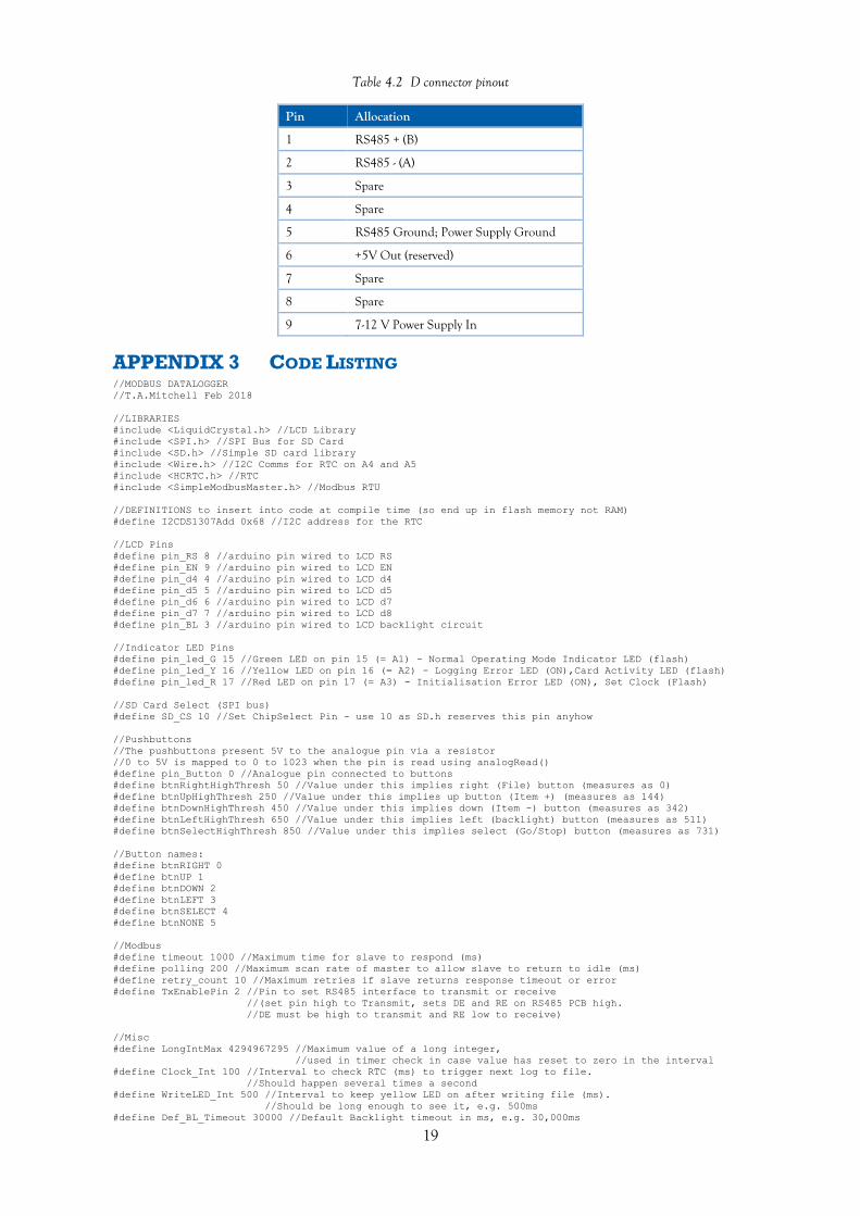
Table 4.2 D connector pinout
Pin Allocation
1 RS485 + (B)
2 RS485 - (A)
3 Spare
4 Spare
5 RS485 Ground; Power Supply Ground
6 +5V Out (reserved)
7 Spare
8 Spare
9 7-12 V Power Supply In
APPENDIX 3 CODE LISTING //MODBUS DATALOGGER
//T.A.Mitchell Feb 2018
//LIBRARIES
#include <LiquidCrystal.h> //LCD Library
#include <SPI.h> //SPI Bus for SD Card
#include <SD.h> //Simple SD card library
#include <Wire.h> //I2C Comms for RTC on A4 and A5
#include <HCRTC.h> //RTC
#include <SimpleModbusMaster.h> //Modbus RTU
//DEFINITIONS to insert into code at compile time (so end up in flash memory not RAM)
#define I2CDS1307Add 0x68 //I2C address for the RTC
//LCD Pins
#define pin_RS 8 //arduino pin wired to LCD RS
#define pin_EN 9 //arduino pin wired to LCD EN
#define pin_d4 4 //arduino pin wired to LCD d4
#define pin_d5 5 //arduino pin wired to LCD d5
#define pin_d6 6 //arduino pin wired to LCD d7
#define pin_d7 7 //arduino pin wired to LCD d8
#define pin_BL 3 //arduino pin wired to LCD backlight circuit
//Indicator LED Pins
#define pin_led_G 15 //Green LED on pin 15 (= A1) - Normal Operating Mode Indicator LED (flash)
#define pin_led_Y 16 //Yellow LED on pin 16 (= A2) - Logging Error LED (ON),Card Activity LED (flash)
#define pin_led_R 17 //Red LED on pin 17 (= A3) - Initialisation Error LED (ON), Set Clock (Flash)
//SD Card Select (SPI bus)
#define SD_CS 10 //Set ChipSelect Pin - use 10 as SD.h reserves this pin anyhow
//Pushbuttons
//The pushbuttons present 5V to the analogue pin via a resistor
//0 to 5V is mapped to 0 to 1023 when the pin is read using analogRead()
#define pin_Button 0 //Analogue pin connected to buttons
#define btnRightHighThresh 50 //Value under this implies right (File) button (measures as 0)
#define btnUpHighThresh 250 //Value under this implies up button (Item +) (measures as 144)
#define btnDownHighThresh 450 //Value under this implies down (Item -) button (measures as 342)
#define btnLeftHighThresh 650 //Value under this implies left (backlight) button (measures as 511)
#define btnSelectHighThresh 850 //Value under this implies select (Go/Stop) button (measures as 731)
//Button names:
#define btnRIGHT 0
#define btnUP 1
#define btnDOWN 2
#define btnLEFT 3
#define btnSELECT 4
#define btnNONE 5
//Modbus
#define timeout 1000 //Maximum time for slave to respond (ms)
#define polling 200 //Maximum scan rate of master to allow slave to return to idle (ms)
#define retry_count 10 //Maximum retries if slave returns response timeout or error
#define TxEnablePin 2 //Pin to set RS485 interface to transmit or receive
//(set pin high to Transmit, sets DE and RE on RS485 PCB high.
//DE must be high to transmit and RE low to receive)
//Misc
#define LongIntMax 4294967295 //Maximum value of a long integer,
//used in timer check in case value has reset to zero in the interval
#define Clock_Int 100 //Interval to check RTC (ms) to trigger next log to file.
//Should happen several times a second
#define WriteLED_Int 500 //Interval to keep yellow LED on after writing file (ms).
//Should be long enough to see it, e.g. 500ms
#define Def_BL_Timeout 30000 //Default Backlight timeout in ms, e.g. 30,000ms

20
#define LCD_UD_Int 900 //LCD Update Interval (ms).
//Should happen just over once a second so clock seconds increment nicely
#define But_Int 500 //Maximum button press interval (ms),
//stops multiple triggering of button command actions due to fast running of code.
//500ms is suitable, short enough not to be noticeable by user,
//but long enough to debounce
#define Msg_Delay 5000 //Delay (ms) after certain LCD messages before proceeding to next action
// that might write to the LCD, e.g. 5,000ms
//GLOBAL VARIABLES
unsigned int LogInterval = 1; //Logging interval in seconds (overwritten with value from config file)
byte QtyRegs = 0; //Number of registers defined in config file to be read
byte newFiles; //How often to create a new datafile, value is the number of digits in the name
//(without extension) of file to create each time, minus 1
//(1 for yearly, 3 for monthly, 5 for daily and 7 for hourly)
byte lcd_key = btnNONE; //Button number pressed by user, see function read_LCD_buttons
int adc_key_in = 0; //Analogue value of button pin
char logger_status; //Logger Status - G=Go, S=Stop, E=Card Error, M-Modbus Error,
//H=Synch to hour (persistent), h=Synch to hour (not on subsequent resets)
char DisableStop; //Stop logging using pushbutton only available if 'N',
//note if not 'N' synch to hour can be overridden by pressing button to start logging
byte disp_reg = 0; //Register to display on LCD (zero based) - changeable using buttons
byte FileN = 99; //File Number that can be incremented by user
//Timer Variables
unsigned long previousMillis; //Old timer value used to trigger RTC check
unsigned long writeMillis; //Timer value at last card write –
//used to keep yellow LED on for a short period after write
unsigned long Prev_LCD_UD = 0; //Timer at last LCD update
unsigned int Secs = 65534; //Elapsed seconds (read from RTC) since values last logged,
//large value ensures logging starts immediately
byte OldSecs; //Previous seconds value read from RTC - to detect change in RTC seconds to
//trigger logging on an interval defined in seconds
byte OldHour; //Used for synch to midnight start - only start logging when hour increments
//LCD Backlight Timer
unsigned long oldBLTime=0; //Time backlight last turned on
unsigned long BL_Timeout = 0; //Backlight timeout in ms
//Previous button Press
unsigned long OldButTime = 0; //Time of last button press
//Modbus Error Flags
byte MErrorMin = 1; //MODBUS error condition, set to zero (no error) whenever modbus reading
//successful for all registers and reset to 1 (error) after each write to file
//MODBUS data structures
#define TOTAL_NO_OF_REGISTERS 10 //Max number of registers to log, used to allocate memory,
//same as total packets as all packets are sized for one register
// Create an array of Packets to be configured
Packet packets[TOTAL_NO_OF_REGISTERS];
//Create an array to hold returned data in its raw form of unsigned integers
unsigned int holdingRegs[TOTAL_NO_OF_REGISTERS];
byte RegOffset = 0; //Bugfix for values being returned in wrong array subscript in holdingRegs.
//Determined by testing for each baud and parity setting. 0 if no adjustment,
//1 adds one to subscript and highest number becomes zero (if only one register, is
//unaffected)
//INITIALISE DEVICES
LiquidCrystal lcd( pin_RS, pin_EN, pin_d4, pin_d5, pin_d6, pin_d7); //Initialise LCD
HCRTC HCRTC; //Initialise RTC library
//Setup function reads or creates a config file
//Sets up the serial port as modbus slave
//Updates the RTC if the config file requests this (then writes to config file to stop future RTC
//update on reset)
void setup()
{
//Local variables for config
unsigned long serBaud; //Baud Rate
byte serParity; //Parity N/O/E = None/Odd/Even
byte serStop; //1 or 2
byte serConfig; //Value to set Data bits, parity and stop bits
byte dataRead; //Raw data from file
unsigned int slaveID, slaveReg, lineStartPos, x = 0; //Parameters to read slave ID and registers
//from file
byte func, invalidEntry = 0, commaCount = 0; //Various variables used to read register parameters from
//file
byte rtcData[6]; //Store elements of date and time to write to RTC to set it
byte i; //Counter to loop over characters
char BaudStr[7]; //Reads baud rate as series of character digits
char tempStr[6]; //Reads log rate, file number and register number as series of character digits
char timeStr[3]; //Reads in the two digits of each time variable
unsigned int logRate; //Log rate in raw state read from file
// set up the LCD's number of columns and rows:
lcd.begin(16, 2);

21
// Initialise backlight
BL_Timeout = Def_BL_Timeout; //Backlight timeout to default
digitalWrite(pin_BL, LOW); //Ensures pullup disabled to avoid damage due to backlight circuit bad
//design
pinMode(pin_BL, INPUT); //Set Backlight On
//Initialise LED Pins
pinMode(pin_led_G, OUTPUT);
pinMode(pin_led_Y, OUTPUT);
pinMode(pin_led_R, OUTPUT);
//Initialise RS485 Pin
pinMode(TxEnablePin, OUTPUT);
digitalWrite(TxEnablePin,LOW);//Receive 485
//Initialise SD card pin
pinMode(SD_CS, OUTPUT);
digitalWrite(SD_CS, HIGH);
//Initialise RTC
HCRTC.RTCRead(I2CDS1307Add);
//Open up the SD Card
if (!SD.begin(SD_CS)) //If fail to initialise SD comms trigger error condition and message
{
lcd.print(F("SD Card Error"));
digitalWrite(pin_led_R, HIGH); //RED LED ON
//Exit setup
return;
}
else //card is present
{
//Does the config file exist?
if (!SD.exists("modlog.cfg")) //If config file missing create an example and trigger error condition
//and message
{
//If no config file, create am example
SdFile::dateTimeCallback(dateTime); //Set datestamp for file
File dataFile = SD.open("modlog.cfg", FILE_WRITE); //create example file
if (dataFile)
{
//Create example
//F() stores strings in flash memory rather than RAM
//Example for ABB B21 meter, 9600,8O1, 5 minute logging, new file daily, log all 4 registers
//of active import (20480-20483), 2 registers of L1-N voltage (23296-23297),
//2 registers of L1 Current (23308-23309), L1 frequency (23340)
dataFile.println(F(
"Update Time (N/Y): N\r\n"
"New Time (YYMMDDHHMMSS): 180212130000\r\n"
"Baud: 9600\r\n"
"Parity (O/E/N): O\r\n"
"Stop Bits (1/2): 1\r\n"
"Log Rate (1-65535 S): 300\r\n"
"New File Rate (N/H/D/M/Y): D\r\n"
"Starting File Number (00-99): 99\r\n"
"Initial State (G/S/s/H/h): G\r\n"
"Disable Stop (Y/N): N\r\n"
"Registers to Log (Slave ID,Type (C/S/I/H),Reg No):\r\n"
"6,H,20480\r\n"
"6,H,20481\r\n"
"6,H,20482\r\n"
"6,H,20483\r\n"
"6,H,23296\r\n"
"6,H,23297\r\n"
"6,H,23308\r\n"
"6,H,23309\r\n"
"6,H,23340\r\n"));
dataFile.close(); //close file
lcd.print(F("Config file not"));
lcd.setCursor(0,1); //LCD Column (0-15), row (0-1) //Move to new line
lcd.print(F("found, created"));
digitalWrite(pin_led_R, HIGH); //RED LED ON
//Exit setup
return;
}
else //Failed to create a config file
{
lcd.print(F("Config file not"));
lcd.setCursor(0,1); //LCD Column (0-15), row (0-1) //Move to new line
lcd.print(F("found, failed"));
digitalWrite(pin_led_R, HIGH); //RED LED ON
//Exit setup
return;
}
}
else //Config file is present, read it
{
File dataFile = SD.open("modlog.cfg", FILE_WRITE); //open file, leave datestamp as is
if (dataFile)
{
dataFile.seek(0);//go to start of file

22
dataFile.seek(findNext(dataFile,':') + 1);//Find the first parameter
if (dataFile.peek() == 'Y') //Update RTC specified (Peek reads without changing current
//position in file)
{
dataFile.write('N'); //Change to N so clock not set again on next reset
dataFile.seek(findNext(dataFile,':') + 1);
//Loop over Year (5), Month (4),Date (3), Hour (2), Minute (1), Second (0)
for(i=5; i<255; i--)
{
timeStr[0] = dataFile.read();
timeStr[1] = dataFile.read();
rtcData[i] = atoi(timeStr);
}
//Set RTC
//Display message to press button to set clock
lcd.print(F("Press Go/Stop to"));
lcd.setCursor(0,1);
lcd.print(F("set clock"));
//Wait for keypress
do
{
adc_key_in = analogRead(pin_Button); //Read button
} while ((adc_key_in > btnSelectHighThresh) || (adc_key_in < btnLeftHighThresh)); //Keep
//looping until value is in the range for the Select button
//Set clock
HCRTC.RTCWrite(I2CDS1307Add, rtcData[5], rtcData[4], rtcData[3], rtcData[2], rtcData[1],
rtcData[0], 1); //Set Clock, last parameter is weekday and not used
delay(100); //Delay to let the clock be set
//Message displaying new time
HCRTC.RTCRead(I2CDS1307Add); //Read RTC
lcd.clear();
lcd.print(F("Clock set to:"));
lcd.setCursor(0,1); //LCD Column (0-15), row (0-1) //Move to new line
lcd.print(HCRTC.GetDateString()); //Display date
lcd.setCursor(5,1); //LCD Column 0 (0-15), row 0 (0-1)
lcd.print(" "); //Erase year
lcd.setCursor(6,1); //LCD Column 0 (0-15), row 0 (0-1)
lcd.print(HCRTC.GetTimeString()); //Display time
blinkLED(pin_led_R,1); //blink LED to signify time updated
delay(Msg_Delay); //Pause so can read LCD diagnostic message
}
else //don't need to update time
{
dataFile.seek(findNext(dataFile,':') + 1); //Move to clock set value, but will not be used
}
//Baud rate (read as multiple chars)
dataFile.seek(findNext(dataFile,':') + 1);
i=0;
do
{
dataRead = dataFile.read();
BaudStr[i] = dataRead;
i++;
} while ((dataRead != 13) && (i<7)); //read up to 6 chars or carriage return
serBaud = atol(BaudStr); //can be over 65535 so use atol (ascii to long) instead of
//atoi (ascii to int)
//Parity
dataFile.seek(findNext(dataFile,':') + 1);
serParity = dataFile.read();
//Stop Bits
dataFile.seek(findNext(dataFile,':') + 1);
serStop = dataFile.read();
//Set serConfig from constants
switch (serParity)
{
case 'N':
if(serStop == '1')
{
serConfig = SERIAL_8N1; //This breaks the MODBUS RTU standard but is used by
//some devices
}
else //2 stop bits by default
{
serConfig = SERIAL_8N2;
}
break;
case 'E':
if(serStop == '2')
{
serConfig = SERIAL_8E2; //This breaks the MODBUS RTU standard
}

23
else //1 stop bit by default
{
serConfig = SERIAL_8E1;
}
break;
default: //Odd Parity
if(serStop == '2')
{
serConfig = SERIAL_8O2; //This breaks the MODBUS RTU standard
}
else //1 stop bit by default
{
serConfig = SERIAL_8O1;
}
break;
}
//Set the RegOffset bugfix variable depending on selected comms parameters
//Note: 8E2 not tested, no adjustment made
if ((serBaud == 19200) || (serBaud == 115200) || (serConfig == SERIAL_8N2) ||
(serConfig == SERIAL_8E1))
{
RegOffset = 1;
}
//Log Rate (read as multiple chars)
dataFile.seek(findNext(dataFile,':') + 1);
i=0;
do
{
dataRead = dataFile.read();
tempStr[i] = dataRead;
i++;
} while ((dataRead != 13) && (i<7));
logRate = atoi(tempStr);
//set the logging interval
LogInterval = ((unsigned int)logRate);
//Create new files Hourly, Daily, Monthly or Yearly 0r Never
dataFile.seek(findNext(dataFile,':') + 1);
switch (dataFile.read())
{
case 'H':
newFiles = 7;
break;
case 'D':
newFiles = 5;
break;
case 'M':
newFiles = 3;
break;
case 'Y':
newFiles = 1;
break;
default: //Always use modlog00.csv
newFiles = 0;
}
//Initial file number (if not creating new file based on time)
dataFile.seek(findNext(dataFile,':') + 1);
memset(tempStr, 0, sizeof(tempStr)); //Clear the temporary string
tempStr[0] = dataFile.read();//First digit
tempStr[1] = dataFile.read();//Second digit
FileN = atoi(tempStr); //Convert to integer
//Initial State (S/s/G/M/m)
dataFile.seek(findNext(dataFile,':') + 1);
switch (dataFile.peek())
{
case 'h':
dataFile.write('G'); //Non persistent synch to hour - write to file to start
//immediately after subsequent reset
logger_status = 'H'; //Use synch to hour to start logging
break;
case 's':
dataFile.write('G'); //Non persistent stop - write to file to start immediately
//after subsequent reset
logger_status = 'S'; //Use synch to hour to start logging
break;
default: //Any other value
logger_status = dataFile.read(); //Read value from file and assign directly
break;
}
//Disable Stop (Y/N)
dataFile.seek(findNext(dataFile,':') + 1);
DisableStop = dataFile.read();
//Registers to log
dataFile.seek(findNext(dataFile,':') + 1);

24
do //scan the remaining data in the file to see if there are 2 commas on each line
{
lineStartPos = dataFile.position(); //save this position, so can return here
commaCount = 0; //reset the count
do
{
dataRead = dataFile.read();
if (dataRead == ',')
{
commaCount++;//count up the commas
}
} while ((dataRead != 255) && (dataRead != 13)); //keep going until end of file or
//carriage return
if (commaCount == 2) //if it's got 2 commas assume a valid slaveid, type and register
{
dataFile.seek(lineStartPos);
i=0;
memset(tempStr, 0, sizeof(tempStr)); //Clear the temporary string
do
{
dataRead = dataFile.read();
tempStr[i] = dataRead;
i++;
} while ((dataRead != ',') && (i<7));
slaveID = atoi(tempStr); //slave id
dataRead = dataFile.read(); //this should be the register type
switch (dataRead)
{
case 'C':
func = READ_COIL_STATUS;
break;
case 'S':
func = READ_INPUT_STATUS;
break;
case 'I':
func = READ_INPUT_REGISTERS;
break;
default: //H - Holding registers
func = READ_HOLDING_REGISTERS;
break;
}
dataFile.read(); //move to the next char
i=0;
memset(tempStr, 0, sizeof(tempStr)); //Clear the temporary string
do
{
dataRead = dataFile.read();
tempStr[i] = dataRead;
i++;
} while ((dataRead != 13) && (i<7));
dataFile.read(); //move to the next char
slaveReg = atoi(tempStr); //get the register number
//Initialize packets (pointer to packet, slave device ID, function code constant, address
//to read (zero based),number of registers to read,subscript of first returned value in
//holdingRegs array
//x is the zero based subscript value
modbus_construct(&packets[x], slaveID, func, slaveReg, 1, x);
x++;
}
else //not two commas on line, assume end of file
{
invalidEntry = 1;
}
} while((!invalidEntry) && (x<TOTAL_NO_OF_REGISTERS)); //keep reading in master packets until
//there are no more
//Store actual number of registers to read - x was incremented after final value so is the total
number of registers
QtyRegs = x;
// Initialize the Modbus comms using the default hardware serial port (Pins D0 and D1) and
//parameters read in from file, packet definitions and array to hold data locally
modbus_configure(&Serial, serBaud, serConfig, timeout, polling, retry_count, TxEnablePin,
packets, x ,holdingRegs); //Changed from max allowable registers (TOTAL_NO_OF_REGISTERS) to
//actual (x), the others are unused
dataFile.close();//close the config file
//Display info about setup on LCD
lcd.clear();
lcd.print(serBaud); //Baud Rate
lcd.print(F(", 8")); //Data Bits fixed as 8 for Modbus RTU
lcd.write((serParity)); //Parity, write not print to display char data type as ascii characters,
//not ascii value
lcd.write(serStop); //Stop Bits, write not print to display char data type as ascii characters,
//not ascii value
25
lcd.setCursor(0,1); //LCD Column (0-15), row (0-1) //Move to new line
lcd.print(LogInterval);
lcd.print(F("s "));
switch (newFiles)
{
case 7:
lcd.print(F("Hourly"));
break;
case 5:
lcd.print(F("Daily"));
break;
case 3:
lcd.print(F("Monthly"));
break;
case 1:
lcd.print(F("Yearly"));
break;
default:
lcd.print(F("Never"));
break;
}
delay(Msg_Delay); //Pause so can read LCD diagnostic message
//Initialise Old Times to trigger first log
HCRTC.RTCRead(I2CDS1307Add); //Update RTC data
OldSecs = HCRTC.GetSecond();
OldHour = HCRTC.GetHour();
//Initialise backlight timeout
oldBLTime = millis();
}
else //couldn't open the config file
{
lcd.print(F("Config file"));
lcd.setCursor(0,1); //LCD Column (0-15), row (0-1) //Move to new line
lcd.print(F("won't open"));
digitalWrite(pin_led_R, HIGH); //RED LED ON
//Exit Setup
return;
}
}
}
}
void loop()
{
//Only do the loop actions if error LED off
if(!digitalRead(pin_led_R))
{
byte rtcData[6];
char fileName[13] = {'m','o','d','l','o','g','0','0','.','c','s','v',0}; //Default filename used if
//no periodic new file
//specified
unsigned long currentMillis = millis();
byte MError = 0; //MODBUS error counter for each register
//Poll the MODBUS devices
modbus_update();
//Store any errors and reset so registers read subsequently
MError = 0; //Reset number of errors this time
for (byte i=1; i<QtyRegs; i++)
{
if (packets[i - 1].connection == false)
{
MError++;
packets[i - 1].connection = true; //Reset the error
}
}
if (MError == 0)
{
MErrorMin = 0;
}
if(Interval_Check(previousMillis, Clock_Int)) //Read the RTC to see if it's time to log
{
previousMillis = currentMillis; //Reset Timer
HCRTC.RTCRead(I2CDS1307Add); //Update RTC data
rtcData[0] = HCRTC.GetSecond(); //Get the seconds from the RTC
if (rtcData[0] != OldSecs) //Seconds have changed on the RTC
{
OldSecs = rtcData[0]; //Update old value to new value
Secs++; //Increment seconds counter NB THIS ASSUMES THE PROCESSING WILL NEVER TAKE > 1 SECOND
digitalWrite(pin_led_G, !digitalRead(pin_led_G)); //Toggle Green LED to flash it
//Synch to hour start check
if(logger_status == 'H') //Synch to hour mode, waiting for hour to change
{
rtcData[2] = HCRTC.GetHour();
26
if(rtcData[2] != OldHour) //Change status to Go if hour has changed on the RTC
{
logger_status = 'G';
}
}
}
}
if ((Secs >= LogInterval) && (logger_status != 'S') && (logger_status != 'H'))//time to log,
//and logging is on, and not waiting for new hour (note logger_status could be G, or E or M if in
//error condition)
{
Secs = 0; //Reset seconds counter
if(newFiles != 0) //Need to assemble filename as it changes periodically
{
//Retrieve each part of date and time as a numeric value (byte data type)
rtcData[0] = HCRTC.GetSecond(); //Seconds
rtcData[1] = HCRTC.GetMinute(); //Minutes
rtcData[2] = HCRTC.GetHour(); //Hours
rtcData[3] = HCRTC.GetDay(); //Date
rtcData[4] = HCRTC.GetMonth(); //Month
rtcData[5] = HCRTC.GetYear(); //Year
//Create the filename from the time in the form YYMMDDHH.csv
//dependent on the config file whether hourly, daily, monthly or yearly
//Omit elements that don't change with the new file interval selected
byte j=0; //j is character number in the filename (zero based, 0..7 for the date part)
//loop over parts of the date and time as stored in rtcData
//Start with year, then month...seconds, stop when counter resets to max value of datatype
//Only add the digits as required by new file interval
for (byte i=5; i<255; i--) //For each part of date
{
if(j < newFiles) //Only add required elements
{
//Add the two digits to the filename: all parts of date and time are 1 or 2 digits
fileName[j] = rtcData[i] / 10 + 0x30; //get first digit by integer division by 10 and
//convert to ascii code of digit by adding 30
j++;
fileName[j] = rtcData[i] % 10 + 0x30; //get second digit by remainder when divided by 10 and
//convert to ascii code of digit by adding 30
j++;
}
}
//add file extension
fileName[j+0] = '.';
fileName[j+1] = 'c';
fileName[j+2] = 's';
fileName[j+3] = 'v';
fileName[j+4] = 0; //end the string
}
else
{
//Fixed filename: add file number
fileName[6] = FileN / 10 + 0x30; //get first digit by integer division by 10 and convert to
//ascii code of digit by adding 30
fileName[7] = FileN % 10 + 0x30; //get second digit by remainder when divided by 10 and convert
//to ascii code of digit by adding 30
}
//Open the file
SdFile::dateTimeCallback(dateTime); //Set datestamp for file
File dataFile = SD.open(fileName, FILE_WRITE); //create it if it doesn't exist
if(dataFile)
{
digitalWrite(pin_led_Y, HIGH); //Turn on Yellow LED while writing file
writeMillis = millis(); //Store timer to keep yellow LED on for a while after finished write
//Insert Date and Time into file
dataFile.print(HCRTC.GetDateString());
dataFile.print(" "); // space between DATE and TIME
dataFile.print(HCRTC.GetTimeString());
dataFile.print(","); // comma after time and date
//Write error flag
dataFile.print(MErrorMin,DEC);
dataFile.print(",");
//log master registers, which are continuously read in background
if (RegOffset == 1) //Bugfix adjusting registers
{
for (byte i=1; i<QtyRegs; i++)
{
dataFile.print(holdingRegs[i],DEC); //Write the value
dataFile.print(",");
}
//Write final register
dataFile.print(holdingRegs[0],DEC); //Write the value
}
else ///Registers as they should be

27
{
for (byte i=0; i<QtyRegs; i++)
{
dataFile.print(holdingRegs[i],DEC); //Write the value
if (i != QtyRegs - 1)
{
dataFile.print(","); //No comma after last register
}
}
}
dataFile.println(""); //new line
dataFile.close(); //close the file
logger_status = 'G'; //Clear any previous E error status
}
else
{
//Card error - note this is not reliable as file writing is cached
logger_status = 'E'; //For display, logging will continue when possible
digitalWrite(pin_led_Y, HIGH); //Yellow LED ON Permanently until next successful write
}
//Modbus comms error - no value read in this logging interval that has just been written to file
if (MErrorMin == 1)
{
logger_status = 'M'; //For display, logging will continue when possible
digitalWrite(pin_led_Y, HIGH); //Yellow LED ON Permanently until next successful write
}
else
{
logger_status = 'G'; //Clear any previous M error status
}
//Reset Error flag for new logging interval
MErrorMin = 1; //Default to error, cleared if read successful before next log
} //End of writing results for logging interval
//Reset Error LED if error conditions have cleared
if ((Interval_Check(writeMillis,WriteLED_Int)) && (logger_status != 'E') && (logger_status != 'M'))
//Keep yellow LED on if in error condition, otherwise turn off after a set time //deleted ==1
{
digitalWrite(pin_led_Y, LOW);//turn off yellow LED
}
if(Interval_Check(Prev_LCD_UD, LCD_UD_Int)) //Update the LCD periodically
{
//Read the clock
HCRTC.RTCRead(I2CDS1307Add);
//Clear Display
lcd.clear(); //In case data not entirely erased by new data
//Display day of month or file number
if((newFiles != 0) || (FileN == 99)) //Display Day Number
{
lcd.print(HCRTC.GetDay()); //Day of month
}
else //Print file number
{
if (FileN < 10) //Print leading zero
{
lcd.print("0");
}
lcd.print(FileN);
}
//Display HH:MM:SS
lcd.setCursor(3,0); //LCD Column (0-15), row (0-1)
lcd.print(HCRTC.GetTimeString()); //Time
//Display long backlight timeout *
if (BL_Timeout != Def_BL_Timeout)
{
lcd.print(F("*"));
}
//Display logger status
lcd.setCursor(12,0); //LCD Column (0-15), row (0-1)
lcd.print(logger_status);
//Display current value of the selected register (changeable with up/down buttons)
//Display register subscript (1-based)
lcd.setCursor(14,0); //LCD Column (0-15), row (0-1)
lcd.print(disp_reg + 1);
//Display Slave ID (3 digits)
lcd.setCursor(0,1); //LCD Column (0-15), row (0-1) //Move to new line
lcd.print(packets[disp_reg].id);
lcd.setCursor(4,1); //LCD Column (0-15), row (0-1)
//Display function code (1 digit: 1: read coil / 2: read input status / 3: read holding registers
/ 4: read input registers )

28
switch (packets[disp_reg].function)
{
case 1:
lcd.print(F("C"));
break;
case 2:
lcd.print(F("S"));
break;
case 3:
lcd.print(F("H"));
break;
case 4:
lcd.print(F("I"));
break;
}
//No space here as not room on screen
//Display which register is being displayed (5 digits)
lcd.print(packets[disp_reg].address);
//Display register value (unsigned int - so 5 digits)
lcd.setCursor(11,1); //LCD Column (0-15), row (0-1)
if (RegOffset == 1) //Bugfix adjusts array subscript
{
if(disp_reg == (QtyRegs - 1)) //also if QtyRegs = 1
{
lcd.print(holdingRegs[0]);
}
else
{
lcd.print(holdingRegs[disp_reg + 1]);
}
}
else //No array subscript adjustment
{
lcd.print(holdingRegs[disp_reg]);
}
//Reset LCD refresh timer
Prev_LCD_UD=millis();
}
// read the buttons
read_LCD_buttons();
//Action on keypress
switch (lcd_key) // depending on which button was pushed, an action is performed
{
case btnSELECT:
//Toggle Log on / off if not disabled
if((logger_status != 'G') && (logger_status != 'E') && (logger_status != 'M'))
//Start if Stopped or Synch to Hour
{
logger_status = 'G';
Secs = 65534; //Log first value ASAP
}
else if ((DisableStop == 'N') &&
((logger_status == 'G') || (logger_status == 'E') || (logger_status == 'M')))
//Logging, so stop unless stop function disabled
{
logger_status = 'S';
}
break;
case btnUP:
//Increase register displayed on LCD
if(disp_reg == (QtyRegs - 1))
{
disp_reg = 0;
}
else
{
disp_reg++;
}
break;
case btnDOWN:
//Decrease register displayed on LCD
if(disp_reg == 0)
{
disp_reg = QtyRegs - 1;
}
else
{
disp_reg--;
}
break;
case btnLEFT:
//Toggle backlight timeout default or 1 hour
if (BL_Timeout == Def_BL_Timeout)
{
BL_Timeout = 3600000; //1 hour
}
else
{
BL_Timeout = Def_BL_Timeout; //Default value
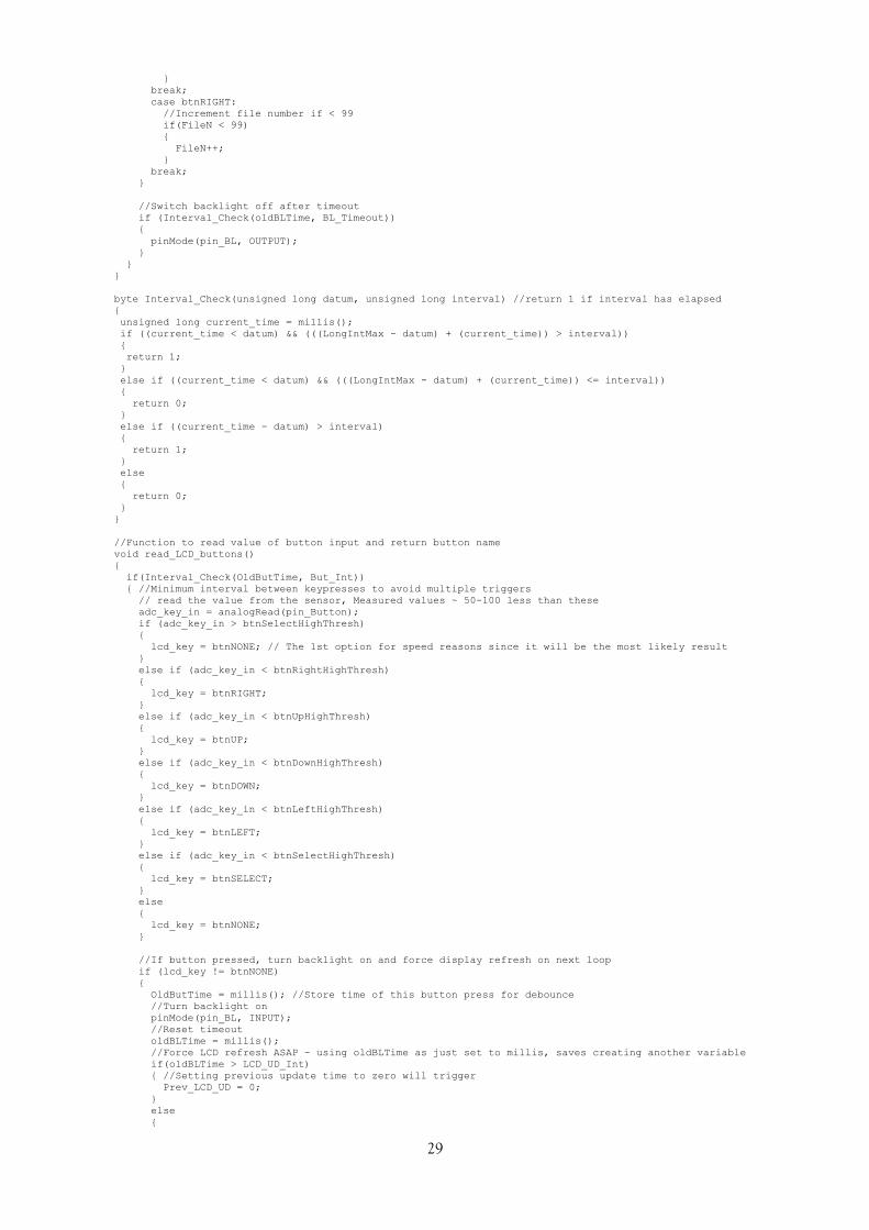
29
}
break;
case btnRIGHT:
//Increment file number if < 99
if(FileN < 99)
{
FileN++;
}
break;
}
//Switch backlight off after timeout
if (Interval_Check(oldBLTime, BL_Timeout))
{
pinMode(pin_BL, OUTPUT);
}
}
}
byte Interval_Check(unsigned long datum, unsigned long interval) //return 1 if interval has elapsed
{
unsigned long current_time = millis();
if ((current_time < datum) && (((LongIntMax - datum) + (current_time)) > interval))
{
return 1;
}
else if ((current_time < datum) && (((LongIntMax - datum) + (current_time)) <= interval))
{
return 0;
}
else if ((current_time - datum) > interval)
{
return 1;
}
else
{
return 0;
}
}
//Function to read value of button input and return button name
void read_LCD_buttons()
{
if(Interval_Check(OldButTime, But_Int))
{ //Minimum interval between keypresses to avoid multiple triggers
// read the value from the sensor, Measured values ~ 50-100 less than these
adc_key_in = analogRead(pin_Button);
if (adc_key_in > btnSelectHighThresh)
{
lcd_key = btnNONE; // The 1st option for speed reasons since it will be the most likely result
}
else if (adc_key_in < btnRightHighThresh)
{
lcd_key = btnRIGHT;
}
else if (adc_key_in < btnUpHighThresh)
{
lcd_key = btnUP;
}
else if (adc_key_in < btnDownHighThresh)
{
lcd_key = btnDOWN;
}
else if (adc_key_in < btnLeftHighThresh)
{
lcd_key = btnLEFT;
}
else if (adc_key_in < btnSelectHighThresh)
{
lcd_key = btnSELECT;
}
else
{
lcd_key = btnNONE;
}
//If button pressed, turn backlight on and force display refresh on next loop
if (lcd_key != btnNONE)
{
OldButTime = millis(); //Store time of this button press for debounce
//Turn backlight on
pinMode(pin_BL, INPUT);
//Reset timeout
oldBLTime = millis();
//Force LCD refresh ASAP - using oldBLTime as just set to millis, saves creating another variable
if(oldBLTime > LCD_UD_Int)
{ //Setting previous update time to zero will trigger
Prev_LCD_UD = 0;
}
else
{

30
Prev_LCD_UD = LongIntMax - LCD_UD_Int;
}
}
}
else //Insufficient time since previous button action: ignore button press
{
lcd_key = btnNONE;
}
}
//Function to flash LED as diagnostic indicator
void blinkLED(byte led, byte ontimes)
{
byte x = 0;
while(x < ontimes)
{
digitalWrite(led,HIGH);
delay(200);
digitalWrite(led,LOW);
delay(200);
x++;
}
delay(400);
}
//Function to find the next instance of a character in the sd card file
unsigned int findNext(File df,byte CharToFind)
{
byte dataRead;
do
{
dataRead = df.read();
} while ((dataRead != 255) && (dataRead != CharToFind)); //end of file or character position
return df.position();
}
//Callback Function to set timestamp for files
void dateTime(uint16_t* ddate, uint16_t* ttime) {
HCRTC.RTCRead(I2CDS1307Add); //Update RTC data
// return date using FAT_DATE macro to format fields
*ddate = FAT_DATE((2000 + HCRTC.GetYear()), HCRTC.GetMonth(), HCRTC.GetDay());
// return time using FAT_TIME macro to format fields
*ttime = FAT_TIME(HCRTC.GetHour(), HCRTC.GetMinute(), HCRTC.GetSecond());
}

31
APPENDIX 4 CODE VERSION HISTORY
Table 4.3 Version history
Version Notes
6 First full test version
7 Various bug fixes
8 Disable stop button and initial state read from file, start on hour option added, always use same data file option added; actions of select and left button swapped
9 Testing of resized arrays for MODBUS data
10 Removed unused string.h library, added wait for keypress before setting clock, simplified button checking, backlight elapsed time reset at end of initialisation code, changed placement of data on LCD during logging, added incrementing filename suffix number option.
11 Added datestamp of files using RTC
12 Simplified determination of parity and stop bit settings
13 Non-persistent stop (“s”) startup mode added; bug fix for year on file datestamps
14 Simplified declaration of data structures for MODBUS
15 Minimalist code for testing MODBUS communications
16 Minimalist code for testing MODBUS communications with commented out code removed
17 V.16 rewritten for different MODBUS library (SimpleModbusNGmaster.zip)
18 As V.14, added backlight indicator (“*”) on LCD, some MODBUS error checking with M error mode and yellow LED indication, added error flag to datafile, hard coded correction added to correct mis-ordered data with certain combinations of baud rate and parity.
APPENDIX 5 TESTING OF COMMUNICATIONS PARAMETERS
Communications were tested using an ABB B21 electricity meter, and also for some combinations on a Schneider PM710 meter (indicated by bold type), with results as tabulated below (OK – no errors, S – data shifted in array, corrected for in code, E – no data returned. Tests have not been performed with 2 stop bits in combination with a parity bit (8E2 or 8O2) or no parity bits with one stop bit (8N1).
Table 4.4 Results of testing combinations of communications parameters.
Baud Rate 8O1 8E1 8N2
1,200 OK E E
2,400 OK E E
4,800 OK E E
9,600 OK S S
19,200 S S S
38,400 OK S S
57,600 OK S S
115,200 S S S

32
APPENDIX 6 EXAMPLE CONFIGURATION FILE
The file below will not reset the RTC (new time not used), sets a baud rate of 9,600, odd parity, 1 stop bit, a log rate of 300 s (5 minutes), creates new datafile daily, (start file number not used), starts logging as soon as possible, enables the stop button, and reads 9 registers as holding registers (these are for an ABB B21 meter, all from most to least significant register for each parameter: four kWh registers, two voltage (L1-N) registers, two L1 current registers, and one L1 frequency register.
Update Time (N/Y): N
New Time (YYMMDDHHMMSS): 180212130000
Baud: 9600
Parity (O/E/N): O
Stop Bits (1/2): 1
Log Rate (1-65535 S): 300
New File Rate (N/H/D/M/Y): D
Starting File Number (00-99): 99
Initial State (G/S/s/H/h): G
Disable Stop (Y/N): N
Registers to Log (Slave ID,Type (C/S/I/H),Reg No):
6,H,20480
6,H,20481
6,H,20482
6,H,20483
6,H,23296
6,H,23297
6,H,23308
6,H,23309
6,H,23340