design of a lbe spallation target for fast-thermal ... of a lbe spallation target for fast-thermal...
TRANSCRIPT

647
DESIGN OF A LBE SPALLATION TARGET FOR FAST-THERMALACCELERATOR-DRIVEN SUB-CRITICAL SYSTEM (ADS)
P. Satyamurthy and K. BiswasLaser and Plasma Technology Division
Bhabha Atomic Research Centre (BARC), Trombay, Mumbai-400085, India
Abstract
Preliminary design of the Indian 750 MWth fast-thermal ADS indicated that a fairly large thermalpower was possible with a proton beam of 1 GeV and current in the range 2-3 mA. In this paper,preliminary thermal-hydraulic studies carried out on the spallation target of window type ADS basedon LBE, with a thermal power of 100 MW in the fast zone, are presented. The studies have beencarried out both for buoyancy as well as gas driven target systems and complete analysis of the loopconsisting of spallation region, riser, two-phase flow region of the riser (for gas-driven target) heatexchanger, downcomer etc has been done. The model is based on one-dimensional single and two-phase flow. Parametric analysis for different flow rates, beam currents (2 and 3 mA and 1 GeV),geometry etc is presented and comparison made between buoyancy and gas-driven systems.

648
Introduction
Accelerator-driven Sub-critical Systems (ADS) have evoked considerable interest in recentyears. [1] In earlier publications [2,3], the BARC group proposed a one-way coupled booster reactorsystem, which could be operated at proton beam currents as low as 1-3 mA for a power output of750 MWth. Here, the basic idea is to have a fast booster reactor zone of low power (~ 100 MWth),which is separated, by a large gap from the main thermal reactor of 650 MWth. In this preliminarydesign, the fast core consists of 48 hexagonal fuel bundles each containing 169 fuel pins of 8.2 mmdiameter arranged in 11.4 mm triangular array pitch. The average thermal power per fuel pin is about13.46 kW. However, due to neutron flux peaking effect, the maximum fuel pin power can be up to2.5 times this average power. The thermal reactor consists of heavy water as moderator and coolantsimilar to a typical CANDU type Indian PHWR except for fuel composition or alternatively AHWR.
In order to develop ADS system as a long-term programme, basic R&D programme has beeninitiated to study spallation target. For this purpose, the process of development of CFD codes andsetting up of experimental target loops for simulation of thermal-hydraulics and diagnostics havealready been initiated. In this paper preliminary thermal-hydraulic studies carried out for moltencirculating LBE target for the beam currents in the range of 2-3 mA and energy of 1 GeV have beenpresented.
Selection of target loop
For our programme, we have chosen molten LBE as target with separated loop. Presently we areconsidering both window as well as windowless configurations. For window configuration, bothbuoyancy and gas driven circulation have been considered (Figure 1). [4] In this paper, studies carriedout for window configuration are presented.
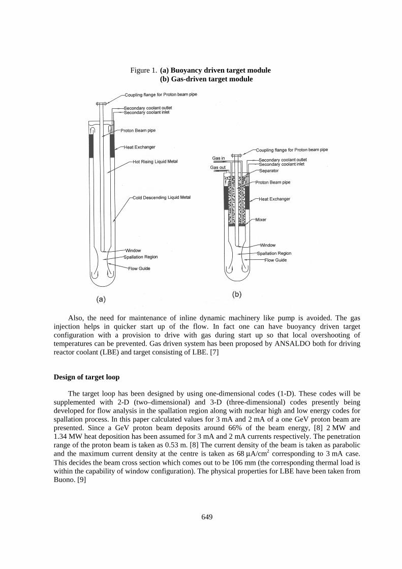
Flow under natural convection (buoyancy driven flow)
In this design (Figure 1a), flow of liquid metal of spallation target is induced by buoyancy force.A large value for volumetric expansion coefficient of LBE and high boiling temperature (1 670°C)helps in this regard. The heat deposition by the proton beam raises the fluid temperature in the hot legwhile the cold leg temperature is maintained through the secondary coolant flow in heat exchanger.The higher the temperature difference, greater will be the fluid flow. However, due to corrosion theremay be an upper limit to the temperature difference that can be maintained. [5,6] This is a passive,self-driven flow system and hence conducive to enhancing the safety feature of the ADS. The maindisadvantage of this system is the size of the target loop. In order to ensure that buoyancy head isadequate for required cooling, either the height or diameter of the loop becomes large. Anotherdisadvantage with buoyancy driven system is the likely over shooting of the coolant temperatureduring start up or fast transients when sufficient buoyancy head is not available (this puts the limit onthe rate at which beam current is increased during start up).
Flow under gas-injection enhanced buoyancy driven flow
In this system (see Figure 1b), the effects of natural convection are reinforced by way of mixing agas to create two-phase flow in the riser leg, which increases available pressure head to drive theliquid metal flow. Since an inert gas is introduced in the liquid heavy metal, which separates out in theseparator tank, it may be possible to use this gas loop to remove online, gaseous spallation productsand vapours like polonium and mercury. In this configuration, it is possible to build a compact targetloop system.
649
Figure 1. (a) Buoyancy driven target module(b) Gas-driven target module
Also, the need for maintenance of inline dynamic machinery like pump is avoided. The gasinjection helps in quicker start up of the flow. In fact one can have buoyancy driven targetconfiguration with a provision to drive with gas during start up so that local overshooting oftemperatures can be prevented. Gas driven system has been proposed by ANSALDO both for drivingreactor coolant (LBE) and target consisting of LBE. [7]
Design of target loop
The target loop has been designed by using one-dimensional codes (1-D). These codes will besupplemented with 2-D (two–dimensional) and 3-D (three-dimensional) codes presently beingdeveloped for flow analysis in the spallation region along with nuclear high and low energy codes forspallation process. In this paper calculated values for 3 mA and 2 mA of a one GeV proton beam arepresented. Since a GeV proton beam deposits around 66% of the beam energy, [8] 2 MW and1.34 MW heat deposition has been assumed for 3 mA and 2 mA currents respectively. The penetrationrange of the proton beam is taken as 0.53 m. [8] The current density of the beam is taken as parabolicand the maximum current density at the centre is taken as 68 µA/cm2 corresponding to 3 mA case.This decides the beam cross section which comes out to be 106 mm (the corresponding thermal load iswithin the capability of window configuration). The physical properties for LBE have been taken fromBuono. [9]

650
Loop calculations for buoyancy driven window configuration
As shown in the Figure 1, the target loop is an axi-symmetric cylindrical device and the loopconsists of spallation region, riser (annular cross-section of proton beam pipe and riser pipe) whereliquid metal flows up after collecting the spallation heat directly from proton beam as well as heatdeposited in the window by the beam. From the exit of the riser, the liquid metal flows into a heatexchanger located at the top of the downcomer. From the exit of the heat-exchanger, the liquid flowsdown in the downcomer (annular cross-section between downcomer pipe and riser pipe). The flowturns around and enters into the nozzle (spallation region) and into the riser (annular cross-section).Flow is assumed to be turbulent and incompressible except for variation of density with temperature(Boussinesq approximation). One-dimensional continuity, momentum and energy equations are usedfor the analysis. Pipe frictional pressure drop, gravity pressure head, pressure change due to velocitychange, pressure drop due to sudden expansion and contraction etc have been incorporated in the code.The proton beam pipe diameter is determined based on the beam cross-section, which in turn isdecided by maximum beam current density allowed by the window. Both riser and downcomer areassumed to be thermally insulated (by thin coating of appropriate ceramic material).
Heat-exchanger design
The coolant circuit envisaged for the Indian ADS target, at present, is a three-loop one. The targetis cooled in the heat exchanger by LBE. This primary coolant in turn gets cooled in an air cooler in thetertiary loop through cross flow heat exchange (in case totally buoyancy driven loop is envisaged) oralternatively water will be used. The heated air is finally released to atmosphere through the stack. Forthe heat-exchanger for the target system, shell-and-tube counter-current configuration is taken. Theoutlet temperatures of the target material in the tube side of the heat exchanger is limited from meltingpoint considerations and from the need for ensuring efficient heat transfer with the primary coolantthrough the entire length of the tube. Hence, the design inlet temperature is chosen to be around275°C. For the primary coolant, the inlet temperature in the shell side of the heat exchanger is limitedby its melting point. Temperature differences across the heat exchanger are restricted to a maximum of200°C as higher temperature differences could lead to undesirable thermal stresses and corrosionproblems.
The number of tube rings and total number of tubes in the heat exchanger are found from theannular dimensions. The shell side and tube side flow areas are calculated from the equivalenthydraulic diameters. For finding the length of the heat exchanger tubes for the required heat exchange,overall heat transfer coefficient, U1 is first evaluated from the wall conductivity and local convectiveheat transfer coefficients, which are found from the convective heat transfer equation for liquid metals.The length of the tubes is then found from the heat flux equation.
Buoyancy driven loop
The sizing of the various components is carried out for the beam current of 3 mA current. Thisessentially decides the proton beam pipe diameter, which is taken as 0.128 m ID and 0.141 m OD(Sch.40 pipe). The riser diameter is chosen as low as possible to minimise frictional pressure drop(0.203 m ID and 0.219 m OD). The nozzle length is taken as 0.7 m. In Figure 2, the required heightsfor various downcomer diameters have been plotted corresponding to three ∆T cases (100, 150 and200°C with inlet temperature of 275°C and the corresponding mass flow rates of 136, 91 and 68 kg/srespectively). Even though we have carried out the calculations for the case of 200°C temperaturedifference in the loop, detailed analysis will need to be carried out whether this much temperature

651
difference can be maintained from corrosion point of view. For ∆T cases of 100 and 150°C, themaximum temperature of the container materials (except for window) being less then 450°C, it ispossible to use austenitic steel (SS 316L). [10] Analysis has been carried out for different nozzlediameters (110, 100 and 90 mm). The main advantage of having smaller nozzle diameter is largervelocity of the liquid metal in the spallation region (which enhances the heat removing capability)with marginal increase in the pressure drop in the loop. For smaller nozzle diameters (less than theproton beam diameter), some heat will be directly deposited in the nozzle walls and some in thedowncomer. However for nozzle diameter of 100 mm, since only edges of the proton beam is exposed,very little heat deposition is expected but with the advantage of higher target velocity.
We see that the required height steeply increases with the reduction of downcomer diameter. Thisis due to steep increase in the heat-exchanger pressure drop. [11,12] The slight increase in the requiredheight with increase of downcomer diameter for the case of 150 and 200°C case (Figure 2) arisesbecause of increase of entrance heat-exchanger pressure (the heat-exchanger dimensions remainingsame for these cases). In the preliminary design of the Fast core, the available diameter for the target is0.378 m. Hence we see that we cannot have buoyancy driven loop with ∆T of 100 (we require ~700 mheight). Table 1 summarises major parameters of two possible configurations for buoyancy drivenloop. In Case-1 the target requires marginally larger space than what is provided in the preliminarydesign of the fast core (0.406 m as against 0.378 m). In Case-2, the target is accommodated with in thespace available in the core. The required height comes out to be around 12 m. The exact nozzlediameter and shape will be determined based on detailed flow analysis in the spallation region.Figure 3 compares the flow parameters when the same target is operated with 2 mA current(corresponding to 1.34 MW of heat). We see that, over all there is a reduction in the coolant flow rateand out let temperature. Reduction in the velocity in the spallation region may not affect the heatextraction since the heat densities also have been reduced (to be validated by CFD code).
Table 1. LBE target parameters for buoyancy driven window configuration for2 MW proton beam (1.0 GeV energy and 3mA current)
Parameter Case-1 Case-2Mass flow rate (kg/s) 91(nom) 68(nom)Inlet temperature (°C) 275 275Outlet temperature (°C) 425 475Proton beam pipe outer diameter (m) 0.141 0.141Riser outer diameter (m) 0.219 0.219Velocity in the riser (m/s) 0.534 0.403Downcomer outer diameter (m) 0.406 0.324Velocity in the downcomer (m/s) 0.115 0.191Heat-exchanger height (m) 1.116 2.308Frictional pressure drop across heat-exchanger (Pa) 3 735 19 858Funnel height (m) 0.7 0.7Funnel internal diameter (m) 0.10 0.11 0.10 0.11Average velocity in the spallation region (m/s) 1.127 0.93 0.85 0.7Total loop height (m) 8.95 7.4 12.10 11.5Buoyancy pressure head (Pa) 16 325 3 735 28 680 19 858Frictional pressure drop across the spallation region (Pa) 7 330 4 948 4 141 2 796

652
Figure 2. Effect of downcomer dimensions on Buoyancy height
Figure 3. Required Buoyancy height for various riser temperaturesand target mass flow rates
Gas-driven window configuration
The main difference in this loop is the presence of a mixer at the bottom of the riser (Figure 1b).Argon (or any suitable gas) at appropriate pressure and flow rate is introduced here. The gas isseparated at the exit of the riser and liquid alone flows in to heat exchanger. For loop design, inaddition to solving single-phase flow equations (similar to that for buoyancy system), two-fluidequations are used for two-phase flow. The two-phase model used here has been validated in amercury-nitrogen loop set up in our institute. [13] The two-phase flow equations consist of continuityequations for liquid metal and gas, combined momentum equation and momentum equation forvapour.

653
Figure 4. Effect of two phase height on gas flow rate
Figure 5. Effect of proton beam current and gas flow rate on liquidmass flow rate and target riser temperature
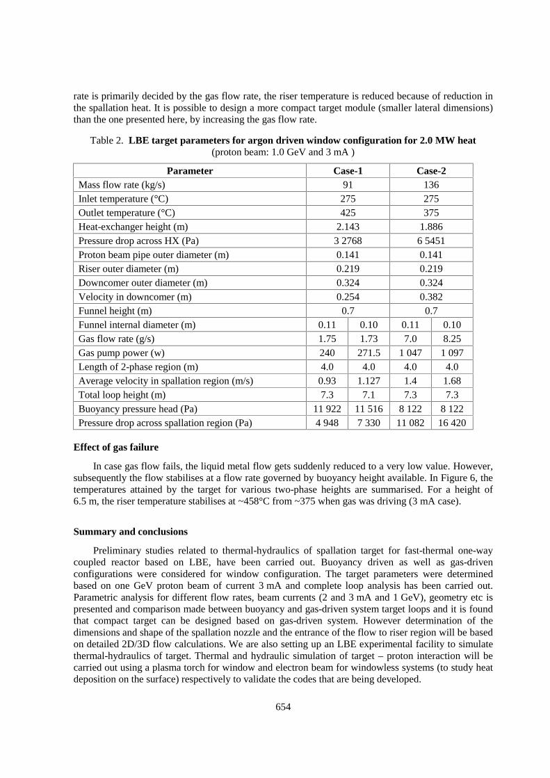
Different expressions for drag force have been used depending upon whether the flow is bubblyor churn or slug. Analysis has been carried out for different two-phase heights (2.0 to 4.0). Therequired gas flow rates have been plotted in the Figure 4 for different ∆T’s. The maximum gas flowrate (Argon) required (corresponding to 2.0 m two-phase height and ∆T of 100°C) is only 16 g/s. Theflow rate is 1g/s for the case of 4.0 m two-phase height and for ∆T of 200°C. Table 2 summarises themajor parameters of gas driven target system. In Figure 5, the performance of the target loop whenoperated at 2 mA current case is presented (for the same gas flow rate). Since the liquid metal flow
654
rate is primarily decided by the gas flow rate, the riser temperature is reduced because of reduction inthe spallation heat. It is possible to design a more compact target module (smaller lateral dimensions)than the one presented here, by increasing the gas flow rate.
Table 2. LBE target parameters for argon driven window configuration for 2.0 MW heat(proton beam: 1.0 GeV and 3 mA )
Parameter Case-1 Case-2Mass flow rate (kg/s) 91 136Inlet temperature (°C) 275 275Outlet temperature (°C) 425 375Heat-exchanger height (m) 2.143 1.886Pressure drop across HX (Pa) 3 2768 6 5451Proton beam pipe outer diameter (m) 0.141 0.141Riser outer diameter (m) 0.219 0.219Downcomer outer diameter (m) 0.324 0.324Velocity in downcomer (m) 0.254 0.382Funnel height (m) 0.7 0.7Funnel internal diameter (m) 0.11 0.10 0.11 0.10Gas flow rate (g/s) 1.75 1.73 7.0 8.25Gas pump power (w) 240 271.5 1 047 1 097Length of 2-phase region (m) 4.0 4.0 4.0 4.0Average velocity in spallation region (m/s) 0.93 1.127 1.4 1.68Total loop height (m) 7.3 7.1 7.3 7.3Buoyancy pressure head (Pa) 11 922 11 516 8 122 8 122Pressure drop across spallation region (Pa) 4 948 7 330 11 082 16 420
Effect of gas failure
In case gas flow fails, the liquid metal flow gets suddenly reduced to a very low value. However,subsequently the flow stabilises at a flow rate governed by buoyancy height available. In Figure 6, thetemperatures attained by the target for various two-phase heights are summarised. For a height of6.5 m, the riser temperature stabilises at ~458°C from ~375 when gas was driving (3 mA case).
Summary and conclusions
Preliminary studies related to thermal-hydraulics of spallation target for fast-thermal one-waycoupled reactor based on LBE, have been carried out. Buoyancy driven as well as gas-drivenconfigurations were considered for window configuration. The target parameters were determinedbased on one GeV proton beam of current 3 mA and complete loop analysis has been carried out.Parametric analysis for different flow rates, beam currents (2 and 3 mA and 1 GeV), geometry etc ispresented and comparison made between buoyancy and gas-driven system target loops and it is foundthat compact target can be designed based on gas-driven system. However determination of thedimensions and shape of the spallation nozzle and the entrance of the flow to riser region will be basedon detailed 2D/3D flow calculations. We are also setting up an LBE experimental facility to simulatethermal-hydraulics of target. Thermal and hydraulic simulation of target – proton interaction will becarried out using a plasma torch for window and electron beam for windowless systems (to study heatdeposition on the surface) respectively to validate the codes that are being developed.

655
Figure 6. Effect of compressor failure on LBE temperatures in donwcomer and riser
Acknowledgement
The authors wish to thank Dr. N. Venkatramani, Head, Laser and Plasma Technology Division,BARC for his valuable suggestions during the preparation of the paper. Special thanks are also due toDr. S.B. Degweker of Theoretical Physics Division, BARC for many useful discussions. We are alsograteful to Dr. S. Buono of CERN for providing the LBE properties and heat density deposition data inthe target due to Proton beam.
REFERENCES
[1] C. Rubbia et al. (1997), CERN-Group Conceptual Design of a Fast Neutron Operated HighPower Energy Amplifier, Accelerator-driven Systems: Energy Generation and Transmutation ofNuclear Waste, Status Report, IAEA-TECDOC-985, November.

656
[2] S.B. Degwekar, D.C. Sahni and S.S. Kapoor (1999), Analysis of a High Gain Energy AmplifierBased on the One Way Coupled Booster Reactor Concept, International Conference on Sub-critical Accelerator-driven Systems, Moscow, Russia, October 11-15.
[3] P. Satyamurthy, S.B. Degwekar and P.K. Nema (2000), Design of a Molten Heavy Metal Coolantand Target for Fast-thermal Accelerator-driven Sub-critical System (ADS), Advisory GroupMeeting on “Design and Performance of Reactor and Blanket Systems with Lead and Lead-Bismuth as Coolant and/or Target Material”, IAEA-AG-1076/IWG-FR/104, Moscow,23-27 October.
[4] Roadmap for Development of Accelerator-driven Sub-critical Reactor Systems (ADS) – AnInterim Report of the Co-ordination Committee on ADS, BARC/2001/R/004, Mumbai, India,2001.
[5] I.J.U. Knebel (1999), (Project Coordinator), Thermal Hydraulic and Material SpecificInvestigations into the Realisation of an Accelerator-driven System (ADS), HGF Strategy FundProject 99/16, Forschungzentrum Karlsruhe, Institute for Kern and Energietechnik, Karlsruhe,Germany.
[6] P.V. Ananthapadmanabhan, personal communication.
[7] Energy Amplifier Demonstration Facility Reference Configuration – Summary Report,ANSALDO, EA B0.001 – Rev.0, January 1999.
[8] S. Buono, Y. Kadi and C. Rubbia (1997), Energy Deposition of a Proton Beam in the LeadTarget of an Energy Amplifier, CERN/ET Internal note 97-11.
[9] S. Buono (1999), Review of Thermal and Physical Properties of Pb-Bi and other Heavy LiquidMetals, First Meeting of the Benchmark Working Group on Heavy Liquid Metal ThermalHydraulics, June 29-30, CERN, Geneva.
[10] A Roadmap for Developing ATW Technology: Target and Blanket System, LA-UR-3002, LosAlamos National Laboratory, USA, September 1999.
[11] P. Satyamurthy and N. Venkatramani (2002), Thermal-hydraulic Issues Related to SpallationNeutron Ttargets of Accelerator-driven Sub-critical Nuclear Reactors, International Symposiumon Recent Trends in Heat and Mass Transfer, IIT Guwahati, India, Jan 6-8, pp. 221-252.
[12] K. Biswas and P. Satyamurthy (2002), Coolant Circuit Design for a Heavy Liquid MetalSpallation Target in an Accelerator-driven Sub-critical Reactor System, International Symposiumon Recent Trends in Heat and Mass Transfer, Indian Institute of Technology, Guwahati,January 6-8, India.
[13] P. Satyamurthy, N.S. Dixit, T.K. Thiyagarajan, N. Venkatramani, A.M. Quraishi and A. Mushtaq(1998), Two-fluid Model Studies for High-density Two-phase Liquid Metal Vertical Flows, Int. J.Multi-phase flows, 24, pp. 721-737.