design of a non-vitiated heater ground test...
TRANSCRIPT
1
DESIGN OF A NON-VITIATED HEATER GROUND TEST FACILITY FOR SUPERSONIC COMBUSTION
By
ADRIAN BLOT
A THESIS PRESENTED TO THE GRADUATE SCHOOL OF THE UNIVERSITY OF FLORIDA IN PARTIAL FULFILLMENT
OF THE REQUIREMENTS FOR THE DEGREE OF MASTER OF SCIENCE
UNIVERSITY OF FLORIDA
2009

2
© 2009 Adrian Blot

3
To Alysen and my Family

4
ACKNOWLEDGMENTS
I thank Dr. Corin Segal for his guidance and for this educational and research opportunity.
I thank my family for all their loving support and I thank my colleagues in the lab who assisted
me in this research.
5
TABLE OF CONTENTS
page
ACKNOWLEDGMENTS ...............................................................................................................4
LIST OF TABLES ...........................................................................................................................7
LIST OF FIGURES .........................................................................................................................8
ABSTRACT ...................................................................................................................................13
CHAPTER
1 SUPERSONIC WINDTUNNEL GROUND TEST FACILITIES .........................................15
Introduction .............................................................................................................................15
Long Duration Facilities .........................................................................................................17
Arc Heated Facilities .......................................................................................................17
Combustion Heaters ........................................................................................................20
Non-Vitiated Heaters .......................................................................................................22
Short Duration Facilities .........................................................................................................22
Gas Driven Shock Tunnels ..............................................................................................24
Detonation Driven Shock Tunnels ..................................................................................24
Piston Driven ...................................................................................................................26
2 NON-VITIATED HEATER DESIGN ...................................................................................29
Design Parameters ..................................................................................................................29
Material Selection ............................................................................................................29
Insulation Sizing ..............................................................................................................32
Insulation Dimensions and Assembly .............................................................................34
Enclosure .........................................................................................................................34
3 PROTOTYPE .........................................................................................................................37
Setup .......................................................................................................................................37
Insulation Sizing .....................................................................................................................37
Experimental Results and Conclusions ..................................................................................42
4 SECOND STAGE HEATER DESIGN ..................................................................................48
Design Parameters ..................................................................................................................48
Heater Design .........................................................................................................................51
Plasma Torch ...................................................................................................................51
Cylinder and Insulation Sizing ........................................................................................51
Fuel Injectors ...................................................................................................................53
Flame Holder ...................................................................................................................61

6
Flanges .............................................................................................................................61
Bellmouth ........................................................................................................................61
5 CONCLUSIONS ....................................................................................................................68
APPENDIX
A NON-VITIATED HEATER DRAWINGS ............................................................................69
B HEATER ENCLOSURE DRAWINGS .................................................................................98
C PROTOTYPE HEATER DRAWINGS ................................................................................112
D SECOND STAGE HEATER DRAWINGS .........................................................................131
E BELLMOUTH DRAWINGS ...............................................................................................144
LIST OF REFERENCES .............................................................................................................157
BIOGRAPHICAL SKETCH .......................................................................................................159

7
LIST OF TABLES
Table page 2-1. List of materials considered and their properties used for material selection ........................31
8
LIST OF FIGURES
Figure page 1-1. Supersonic wind tunnel ground test facilities flight envelopes ..........................................16
1-2. Arc facility configurations ......................................................................................................19
1-3. Layout of the APTU vitiated heater facility ...........................................................................21
1-4. The HTT facility’s vitiated heater combustor ........................................................................21
1-5. The HTF non-vitiating facility layout ....................................................................................23
1-6. Backward and forward operating modes of detonation driven shock tunnels with corresponding wave diagrams ............................................................................................27
1-7. The HEG piston driven shock tube facility operated as a reflected shock tunnel ..................28
2-1. Heater facility diagram with optional second stage heater. ....................................................30
2-2. Insulation spacer required for structural support, insulation displacement, and thermocouple access. .........................................................................................................33
2-3. Insulation cylinder assembly: Semi cylinders, spacers and metal bands ...............................35
2-4. Heater facility within enclosure ..............................................................................................36
3-1. Prototype assembly with insulation ........................................................................................38
3-2. Air flow circuit of prototype system .......................................................................................38
3-3. Insulation sizing analytical results comparing insulation thickness and composite insulation with varying internal diameter ..........................................................................41
3-4. Temperature response of prototype heater .............................................................................43
3-5. Prototype heater tube temperature distribution ......................................................................44
3-6. Prototype efficiency plot ........................................................................................................46
3-7. Specific heat input required for exit air stagnation temperature ............................................47
4-1. Second stage heater assembly to non-vitiated heater .............................................................49
4-2. Second stage heater assembly drawing ..................................................................................50
4-3. Insulation assembly detail drawing ........................................................................................54

9
4-4. Hydrogen mass flow rate required to heat 250g/s of supply air to a specific exit air stagnation temperature with varying input temperartures .................................................56
4-5. Vitiation characteristics of the second stage heater ................................................................57
4-6. Fuel injector detail drawing ....................................................................................................58
4-7. Hydrogen mixing characteristics of two flow rates ................................................................59
4-8. Fuel injector design mixing comparison ................................................................................60
4-9. Flame distribution and stabilization over water cooled coils .................................................62
4-10. Flame holder detail drawing .................................................................................................63
4-11. Second stage heater inlet and exit flanges ............................................................................64
4-12. Bellmouth assembly views ...................................................................................................66
4-13. Bellmouth quarter section showing geometry and grooves for insulation ...........................67
A-1. Non-vitiated heater layout .....................................................................................................70
A-2. Non-vitiated heater bill of materials of all parts ....................................................................71
A-3. Non-vitiated heater bill of materials for assembly ................................................................72
A-4. Collector flange mechanical drawing ....................................................................................73
A-5. Collector branch flange gasket mechanical drawing .............................................................74
A-6. Collector flange end cap mechanical drawing .......................................................................75
A-7. Cold Collector supply flange mechanical drawing ................................................................76
A-8. Cold collector single tube entrance flange mechanical drawing ...........................................77
A-9. Cold collector double tube flange mechanical drawing ........................................................78
A-10. Cold collector single tube exit flange mechanical drawing .................................................79
A-11. Hot collector double tube flange mechanical drawing ........................................................80
A-12. Tube weldment mechanical drawing ...................................................................................81
A-13. Disconnect tube weldment mechanical drawing .................................................................82
A-14. Tube mechanical drawing ....................................................................................................83
A-15. Tube bushing mechanical drawing ......................................................................................84
10
A-16. Cold collector weldment mechanical drawing ....................................................................85
A-17. Cold collector mechanical drawing .....................................................................................86
A-18. Hot collector weldment mechanical drawing ......................................................................87
A-19. Hot collector mechanical drawing .......................................................................................88
A-20. Collector branch weldment mechanical drawing ................................................................89
A-21. Collector branch mechanical drawing .................................................................................90
A-22. Discharge pipe weldment mechanical drawing ...................................................................91
A-23. Discharge exit flange mechanical drawing ..........................................................................92
A-24. Hot collector discharge pipe mechanical drawing ...............................................................93
A-25. Hot collector discharge nipple mechanical drawing ............................................................94
A-26. Hot collector discharge elbow mechanical drawing ............................................................95
A-27. Insulation spacer mechanical drawing .................................................................................96
A-28. Semi cylinder insulation mechanical drawing .....................................................................97
B-1. Enclosure bill of materials for all parts ..................................................................................99
B-2. Enclosure assembly mechanical drawing ............................................................................100
B-3. Frame weldment mechanical drawing .................................................................................101
B-4. Subframe weldment mechanical drawing ............................................................................102
B-5. Angle iron A mechanical drawing .......................................................................................103
B-6. Angle iron C mechanical drawing .......................................................................................104
B-7. Angle iron B mechanical drawing .......................................................................................105
B-8. Angle iron D mechanical drawing .......................................................................................106
B-9. Front panel mechanical drawing ..........................................................................................107
B-10. Bottom front panel mechanical drawing ............................................................................108
B-11. Side panel mechanical drawing .........................................................................................109
B-12. Bottom side panel mechanical drawing .............................................................................110
11
B-13. Top panel mechanical drawing ..........................................................................................111
C-1. Prototype assembly layout ...................................................................................................113
C-2. Prototype bill of material of all parts ...................................................................................114
C-3. Prototype bill of material for assembly ................................................................................115
C-4. Support base weldment mechanical drawing .......................................................................116
C-5. Support base flat pattern sheet metal mechanical drawing ..................................................117
C-6. Support base bend pattern sheet metal mechanical drawing ...............................................118
C-7. Inlet flange base weldment mechanical drawing .................................................................119
C-8. Inlet flange base sheet metal mechanical drawing ...............................................................120
C-9. Brace sheet metal mechanical drawing ................................................................................121
C-10. Threaded insert mechanical drawing .................................................................................122
C-11. Prototype tube weldment mechanical drawing ..................................................................123
C-12. Prototype tube mechanical drawing ...................................................................................124
C-13. Inlet flange mechanical drawing ........................................................................................125
C-14. Outlet flange mechanical drawing .....................................................................................126
C-15. Flange ceramic insert mechanical drawing ........................................................................127
C-16. Ceramic disk with inset mechanical drawing ....................................................................128
C-17. Ceramic disk mechanical drawing .....................................................................................129
C-18. Ceramic spacer mechanical drawing .................................................................................130
D-1. Second stage layout .............................................................................................................132
D-2. Second stage bill of material of all parts .............................................................................133
D-3. Second stage bill of material for assembly ..........................................................................134
D-4. Second stage weldment mechanical drawing ......................................................................135
D-5. Steel outer cylinder mechanical drawing .............................................................................136
D-6. Second Stage inlet flange mechanical drawing ...................................................................137

12
D-7. Second stage exit flange mechanical drawing .....................................................................138
D-8. Permanent insulation mechanical drawing ..........................................................................139
D-9. Removable insulation mechanical drawing .........................................................................140
D-10. Flame holder plate mechanical drawing ............................................................................141
D-11. Flame holder mechanical drawing .....................................................................................142
D-12. Hydrogen fuel injector mechanical drawing ......................................................................143
E-1. Bellmouth assembly for currently used test section .............................................................145
E-2. Bellmouth weldment drawing for currently used test section ..............................................146
E-3. Weldment drawing of bellmouth sections for currently used test section ...........................147
E-4. Large quarter section of bellmouth for currently used test section mechanical drawing .....148
E-5. Small quarter section of bellmouth for currently used test section mechanical drawing .....149
E-6. Bellmouth assembly for new test section .............................................................................150
E-7. Bellmouth weldment drawing for new test section ..............................................................151
E-8. Weldment drawing of bellmouth sections for new test section ...........................................152
E-9. Large quarter section of bellmouth for new test section mechanical drawing .....................153
E-10. Small quarter section of bellmouth for new test section mechanical drawing ...................154
E-11. Bellmouth flange mechanical drawing ...............................................................................155
E-12. General mechanical drawing of bellmouth cooling coil ....................................................156
13
Abstract of Thesis Presented to the Graduate School of the University of Florida in Partial Fulfillment of the
Requirements for the Degree of Master of Science
DESIGN OF A NON-VITIATED HEATER GROUND TEST FACILITY FOR SUPERSONIC COMBUSTION
By
Adrian Blot
August 2009
Chair: Corin Segal Major: Aerospace Engineering
To date, few ground-based experimental facilities for hypersonic flight simulation have the
capacity of performing non-vitiated testing. Vitiated facilities introduce species that affect
chemical reactions during testing. The goal of this work was to investigate the performance of a
design for a new non-vitiated heater ground test facility for supersonic combustion.
The non-vitiated heater has been designed to simulate flight Mach numbers up to Mach 5.
This work shows the feasibility and design of this ground test facility as well as the design of an
optional second stage heater which will allow back-to-back experiments under vitiated and non-
vitiated conditions as well as produce larger Mach numbers. Insulation was designed to improve
the performance of the heater as well as provide structural support and safety.
A scaled down prototype, of the non-vitiated heater, was tested to determine the
performance of the design. Reynolds numbers, based on the inlet air conditions and the stainless
steel tube inner diameter, from 19,000 to 130,000 were tested and the desired stagnation
temperature of 1300K was achieved at a Reynolds number of 42,000. The efficiency of this
heater was found to be dependent on the Reynolds number and the exit stagnation temperature of
the heated air. The efficiency has a maximum value of 90% at a Reynolds number of 85,000 and
decreases linearly at a rate of 4% per 100K of increasing exit air stagnation temperature. The

14
efficiency’s rate of change also depends on the Reynolds number and decreases with increasing
Reynolds number. Further it was found the system heats and cools quickly where temperature
changes of 19K per second was experienced allowing experiments which require fast transients.
A vitiated second stage heater was also designed to simulate Mach numbers up to 6 for a
mass flow rate of 250g/s. This heater uses hydrogen as the working fuel and requires oxygen
replenishment to provide accurate air composition at the test section. This heater is to be installed
downstream of the non-vitiated heater and may be operated independently or simultaneously
with the non-vitiating heater. Hydrogen fuel rates up to 6.0g/s are required to raise the stagnation
temperature of the air to 1800K, the value required to simulate Mach 6 flight conditions. A
bellmouth has also been designed to couple the test section to either heater.
15
CHAPTER 1 SUPERSONIC WINDTUNNEL GROUND TEST FACILITIES
Introduction
The purpose of this work is to present and evaluate a non-vitiated ground test facility for
supersonic combustion to simulate flight condition up to Mach 5. Few wind tunnel testing
facilities are capable of non-vitiated supersonic combustion and achieving high flight enthalpies.
The importance of test facilities is broad, ranging from fundamental research to commercial and
military uses for performance improvements and cost reduction of aerodynamic systems.1 They
are also required to provide data in cases where current analytical models are insufficient or
existing models must be validated.2 As an example, validation is needed for flight Mach numbers
from 3 to 6, which encompasses the flight transition from ramjet to scramjet operation.3
Ground test facilities are specialized to operate within a limited window of test conditions
due to manufacturing difficulties. At high Mach numbers especially above Mach 8, the following
shortcomings arise: adequate test flow uniformity and fluid property equilibrium over a wide
range of conditions cannot be maintained, surface conditions are not identical to models, flow
contamination from surface erosion or vitiation of a pre-combusted gas, and insufficient test
times.2
Operating test times can be used to classify test facilities. The following sections discuss
the different types of supersonic ground test facilities that are currently in use and their primary
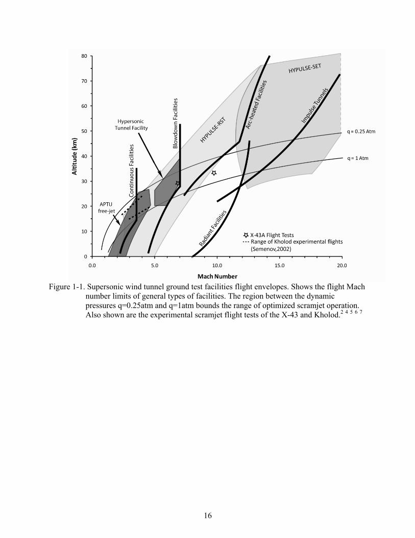
purposes outlining some of advantages and disadvantages. Figure 1-1 shows the equivalent flight
conditions that general types of facilities today are able to simulate and features a few specific
facilities. Shown in the figure is the range of optimized scramjet operation designated by the area
between the two dynamic pressures, q=1atm and q=0.25atm. An overview of main operational
characteristics of several types of facilities follows.
16
Figure 1-1. Supersonic wind tunnel ground test facilities flight envelopes. Shows the flight Mach
number limits of general types of facilities. The region between the dynamic pressures q=0.25atm and q=1atm bounds the range of optimized scramjet operation. Also shown are the experimental scramjet flight tests of the X-43 and Kholod.2 4 5 6 7
17
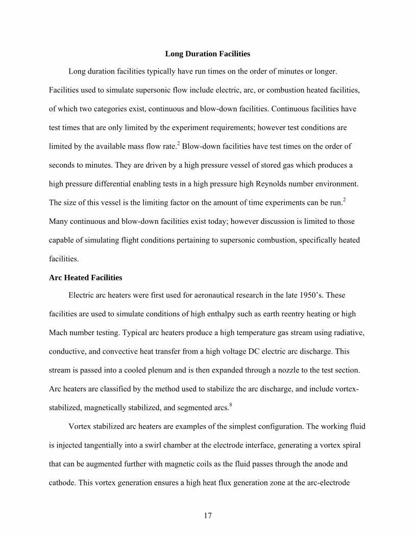
Long Duration Facilities
Long duration facilities typically have run times on the order of minutes or longer.
Facilities used to simulate supersonic flow include electric, arc, or combustion heated facilities,
of which two categories exist, continuous and blow-down facilities. Continuous facilities have
test times that are only limited by the experiment requirements; however test conditions are
limited by the available mass flow rate.2 Blow-down facilities have test times on the order of
seconds to minutes. They are driven by a high pressure vessel of stored gas which produces a
high pressure differential enabling tests in a high pressure high Reynolds number environment.
The size of this vessel is the limiting factor on the amount of time experiments can be run.2
Many continuous and blow-down facilities exist today; however discussion is limited to those
capable of simulating flight conditions pertaining to supersonic combustion, specifically heated
facilities.
Arc Heated Facilities
Electric arc heaters were first used for aeronautical research in the late 1950’s. These
facilities are used to simulate conditions of high enthalpy such as earth reentry heating or high
Mach number testing. Typical arc heaters produce a high temperature gas stream using radiative,
conductive, and convective heat transfer from a high voltage DC electric arc discharge. This
stream is passed into a cooled plenum and is then expanded through a nozzle to the test section.
Arc heaters are classified by the method used to stabilize the arc discharge, and include vortex-
stabilized, magnetically stabilized, and segmented arcs.8
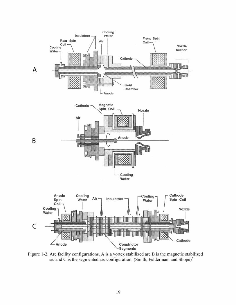
Vortex stabilized arc heaters are examples of the simplest configuration. The working fluid
is injected tangentially into a swirl chamber at the electrode interface, generating a vortex spiral
that can be augmented further with magnetic coils as the fluid passes through the anode and
cathode. This vortex generation ensures a high heat flux generation zone at the arc-electrode
18
contact site and minimizes contact wear on the cathode by distribution over a relatively large
surface area. Vortex stabilized facilities are inexpensive, easily maintained, reliable, and is
capable of very long run times of minutes to hours. Drawbacks to this approach include issues of
flow quality and reduced efficiency which arise from an uncontrolled arc length and a fixed
voltage differential. Due to the fixed voltage differential a greater magnitude of current is
required to increase the overall power, however this results in greater electrode erosion.
Magnetic stabilized heaters use a center-axis anode discharging to the outer wall. The stability of
the arc column is maintained through the use of external magnetic coils placed around the heater
plenum.8
Segmented arcs form the modern high performance arc heater, essentially a hybrid of the
vortex and magnetic stabilized arc heaters with the addition of a segmented construction which
efficiently produces clean high temperature gas. Only segmented arc heaters are able to provide
the combination of total pressure, enthalpy, and run times required for many endoatmospheric
aerothermal simulations. The use of this type of arc-heater has the following performance
advantages: high efficiency by the optimization of heat transfer from arc column to working gas,
arc stability at high pressures, high voltage operations resulting in lower required currents and
reduced electrode erosion, and repeatability of the flow field with respect to total enthalpy. The
disadvantages of this heater are related to initial and maintenance costs as well as the relative
complexity of such a system.8 The SCIROCCO facility in Italy is a segmented arc facility which
is capable of producing stagnation temperatures from 2,000 to 10,000K producing test conditions
up to Mach 12. The main purpose of this facility is to duplicate aerothemodynamic conditions
encountered by space vehicles for Earth reentry. The facility requires 70MW power and
processes air over a pressure range of 1-17 bar.4 Figure 1-2 shows the configurations of these
three types.
19
Figure 1-2. Arc facility configurations. A is a vortex stabilized arc B is the magnetic stabilized
arc and C is the segmented arc configuration. (Smith, Felderman, and Shope)8

20
In general, arc heated facilities have several drawbacks with respect to supersonic
combustion. They are limited in the pressures they are able to achieve due to the volume flow
rate of fluid that can be passed through the arc to achieve the desired temperatures.2 The arc of
plasma used to heat the fluid creates contaminants in the flow from the dissociation of molecules
in the gas mixture. This results in different flow characteristics which can affect results in
combustion facilities due to the addition of free radicals. These radicals can influence flame
ignition and stability.
Combustion Heaters
Combustion heaters use fuels mixed into the test flow where they are combusted to
increase the temperature of the fluid. The total temperature of the fluid that can be achieved in
these heaters is directly dependent on the fuel being used. For hydrocarbons this limit
corresponds to stagnation temperatures required for Mach 7 while the use of hydrogen allows for
even higher Mach numbers.2
This method of heating produces a number of undesired effects. The process of
combustion introduces combustion products, unburned fuel, and alters the oxygen content of the
test air. Oxygen enrichment and replenishment is required to provide the correct oxygen mole
fraction for the test section and ensure proper fuel combustion.5 This creates the need to control
and monitor the oxygen content of the test fluid to ensure proper amounts of oxygen exist in the
test flow to properly simulate atmospheric conditions that will be used in combustion tests. The
Aerodynamic and Propulsion Test Unit (APTU) facility uses Butane fuel in the combustor to
increase the stagnation temperature of the working fluid to 1100K for test time up to 12 minutes.
Figure 1-3 is a current schematic of the APTU facility and Figure 1-4 details the High
Temperature Tunnel (HTT) facility’s combustor which uses methane fuel to increase the
stagnation temperature of the working fluid to 2200K with pressures from 4.1 to 27.6MPa. After

21
Figure 1-3. Layout of the APTU vitiated heater facility. Butane and oxygen are mixed in the vitiated air heater where the fuel is combusted. The air is then expanded through the nozzle to the test section and ejected. (Rigney and Garrard)5
Figure 1-4. The HTT facility’s vitiated heater combustor. Details components and shows fuel,
air, and oxidizer supply. (Hodge and Harvin)9

22
combustion the test gas is expanded through a nozzle providing Mach numbers up to 7 and then
is exhausted to a 26ft diameter spherical test chamber with test times up to 2 minutes.9
Non-Vitiated Heaters
Heaters of this type introduce no flow contaminants into the test flow. Methods used to
achieve this involve electric resistance heating and other specialized heat transfer devices or
methods. One method of electric resistance heating involves passing air over a heating element.
Alternatively, storage heating can be used as done is by the High Temperature Facility (HTF)
facility at the NASA Glenn Research center.
Storage heaters transfer heat to the working fluid after preheating. Preheating can be done
by combustion or electrical heating. The HTF passes nitrogen through an induction heated
graphite core where oxygen is later added and mixed to obtain proper nitrogen to oxygen
concentrations to match that of air. The graphite core is heated via induction from a current that
is passed through its shell6 (Figure 1-5). The core is 12.2 m tall and weighs 27,000 kg and is
heated at a maximum rate of 28K per hour to minimize thermal stresses, resulting in 100 plus
hours to reach a temperature of 2800K. This facility has a domed test chamber with a diameter of
7.6m with a thrust stand that can handle a test article up to 7300kg.6
Short Duration Facilities
These facilities are shock tunnels and have run times on the order of milliseconds to a few
seconds. Test gas conditions are achieved through a compression process resulting from a shock
wave propagating through the tunnel at the local speed of sound of the test gas. Run times are
highly dependent on the fluid temperature, which determines the local speed of sound, and
physical length of the tube. This relation of the speed of sound to temperature determines the
velocity of the shock and expansion waves and the length of the tube determines the duration of
the test by the time it takes for the shock wave to travel the length of the tube.
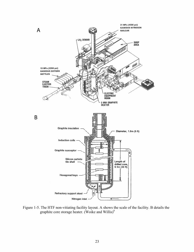
23
Figure 1-5. The HTF non-vitiating facility layout. A shows the scale of the facility. B details the graphite core storage heater. (Woike and Willis)6
24
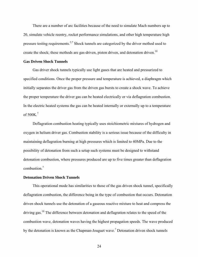
There are a number of arc facilities because of the need to simulate Mach numbers up to
20, simulate vehicle reentry, rocket performance simulations, and other high temperature high
pressure testing requirements.2,7 Shock tunnels are categorized by the driver method used to
create the shock; these methods are gas-driven, piston driven, and detonation driven.10
Gas Driven Shock Tunnels
Gas driver shock tunnels typically use light gases that are heated and pressurized to
specified conditions. Once the proper pressure and temperature is achieved, a diaphragm which
initially separates the driver gas from the driven gas bursts to create a shock wave. To achieve
the proper temperature the driver gas can be heated electrically or via deflagration combustion.
In the electric heated systems the gas can be heated internally or externally up to a temperature
of 500K.7
Deflagration combustion heating typically uses stoichiometric mixtures of hydrogen and
oxygen in helium driver gas. Combustion stability is a serious issue because of the difficulty in
maintaining deflagration burning at high pressures which is limited to 40MPa. Due to the
possibility of detonation from such a setup such systems must be designed to withstand
detonation combustion, where pressures produced are up to five times greater than deflagration
combustion.7
Detonation Driven Shock Tunnels
This operational mode has similarities to those of the gas driven shock tunnel, specifically
deflagration combustion, the difference being in the type of combustion that occurs. Detonation
driven shock tunnels use the detonation of a gaseous reactive mixture to heat and compress the
driving gas.10 The difference between detonation and deflagration relates to the speed of the
combustion wave, detonation waves having the highest propagation speeds. The wave produced
by the detonation is known as the Chapman-Jouguet wave.7 Detonation driven shock tunnels
25
were first used in 1957, however testing was stopped due to high mechanical loading of the
shock tube from the intersection of the reflected and incident shocks. This method was
reintroduced in 1989 when Yu10 used a buffer tube that reduced the high mechanical loads.
Combination of detonation driver and expansion tubes achieve extremely high enthalpy
conditions. The Hypulse facility run by NASA is one such facility having the capacity to
simulate Mach numbers up to 25. This tunnel can be operated as a reflected shock or shock
expansion tunnel.7
Two modes have been developed known as forward and backward driver modes. The
backward mode results in uniform and steady flow condition for a relatively long period of time
and more closely resembles the process of the classical shock tube. This mode uses detonation
between the driver and the driven section where the detonation wave propagates backward into
the driver section leaving behind a quasi-steady flow with constant properties from which the
primary shock is driven into the low pressure section.10
The forward mode creates a detonation wave at the upstream end of the driver section. The
detonation wave ruptures the main diaphragm between the driver and driven section and the high
pressure and temperature behind this wave drives the incident shock, which runs along the driven
section. An issue that occurs under normal operation is the Taylor expansion wave behind the
detonation wave overcomes and attenuates the incident shockwave resulting in unsteady flow
ahead of the nozzle. Several methods have been developed to reduce this phenomenon; however
none have been able to eliminate it. There is a performance gain using the forward mode
detonation driver for today’s existing shock tunnels; however is it does not achieve the
performance, with respect to reservoir pressure and enthalpy, of free- piston shock tunnels. This
is due to the limitation on the temperature of the driver gas from the detonation process. Despite
this the forward detonation mode is used as opposed to piston driven facilities because of the
26
lower initial investment, relative simplicity, and minimal required maintenance.10 Figure 1-6
shows the physical schematics of the two different modes with corresponding wave diagrams.
The wave diagrams show the series of wave propagation and reflections that occur during the
detonation processes.
Piston Driven
This method uses a piston to compress the driver gas until the diaphragm separating the
driver gas from the driven gas ruptures creating the shockwave. The stagnation conditions of the
test gas results after the shock has reflected from the end of the shock tube, and are dependent on
the compression ratio, driver gas composition, diaphragm rupture pressure, and initial pressure of
the driven gas. Due to the small volume of driver gas that results after compression the driver gas
pressure drops rapidly resulting in a rapid decay of shock tube performance. The tuned operation
method was developed to address this issue.11 The result is the piston is accelerated to nearly
sonic speeds to compress the driving gas10, and remains in motion from its momentum as the
diaphragm bursts maintaining the pressure for a longer duration. The piston is decelerated to a
stop at the compression end of the tube by the remaining driver gas after the test period.11
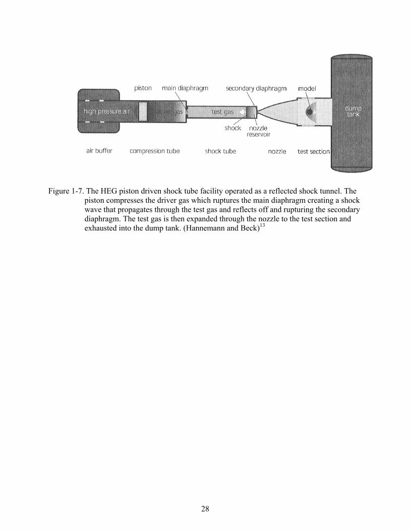
The High Enthalpy Shock Tunnel (HEG) facility (Figure 1-7) is operated as a reflected
shock tunnel and has an overall length of 60m. A piston is accelerated to 1000km/hr to compress
the driver gas and rupture the diaphragm. A shock is generated which travels through the tunnel
and upon reflection ruptures a secondary diaphragm beginning the test. This process creates
stagnation temperatures and pressures up to 9900K and 85MPa respectively.13
A difficulty in the use of heavy pistons lies in their inability to produce stagnation
temperature greater than 2000K. A solution was developed and is the multi-cascade compression
(MCC) method which allows for stagnation temperatures up to 4000K for diatomic gases with
test duration of 50 to 1000ms more than other shock tube methods for similar conditions.12

27
Figure 1-6. Backward and forward operating modes of detonation driven shock tunnels with corresponding wave diagrams. A shows the forward or downstream detonation mode detonation shock tunnel. B shows the backward or upstream detonation mode. (Olivier et al)10
28
Figure 1-7. The HEG piston driven shock tube facility operated as a reflected shock tunnel. The piston compresses the driver gas which ruptures the main diaphragm creating a shock wave that propagates through the test gas and reflects off and rupturing the secondary diaphragm. The test gas is then expanded through the nozzle to the test section and exhausted into the dump tank. (Hannemann and Beck)13
29
CHAPTER 2 NON-VITIATED HEATER DESIGN
Design Parameters
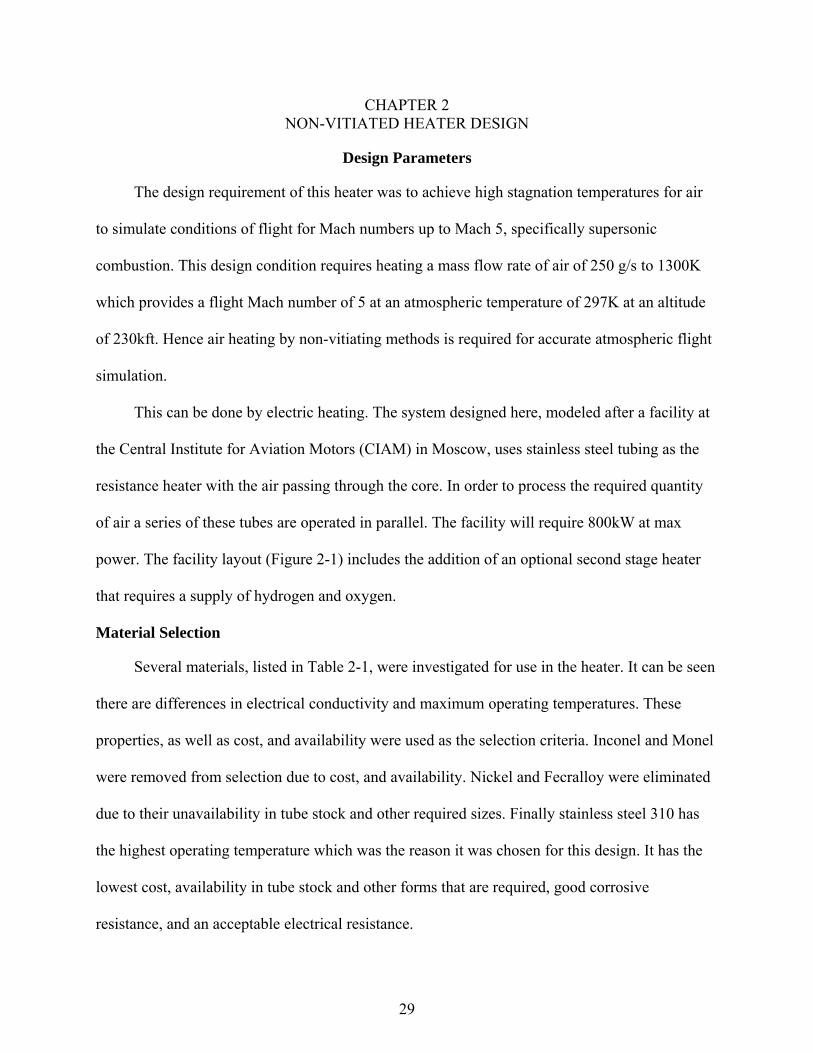
The design requirement of this heater was to achieve high stagnation temperatures for air
to simulate conditions of flight for Mach numbers up to Mach 5, specifically supersonic
combustion. This design condition requires heating a mass flow rate of air of 250 g/s to 1300K
which provides a flight Mach number of 5 at an atmospheric temperature of 297K at an altitude
of 230kft. Hence air heating by non-vitiating methods is required for accurate atmospheric flight
simulation.
This can be done by electric heating. The system designed here, modeled after a facility at
the Central Institute for Aviation Motors (CIAM) in Moscow, uses stainless steel tubing as the
resistance heater with the air passing through the core. In order to process the required quantity
of air a series of these tubes are operated in parallel. The facility will require 800kW at max
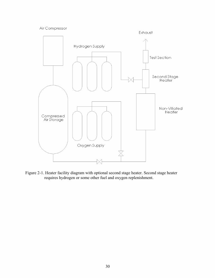
power. The facility layout (Figure 2-1) includes the addition of an optional second stage heater
that requires a supply of hydrogen and oxygen.
Material Selection
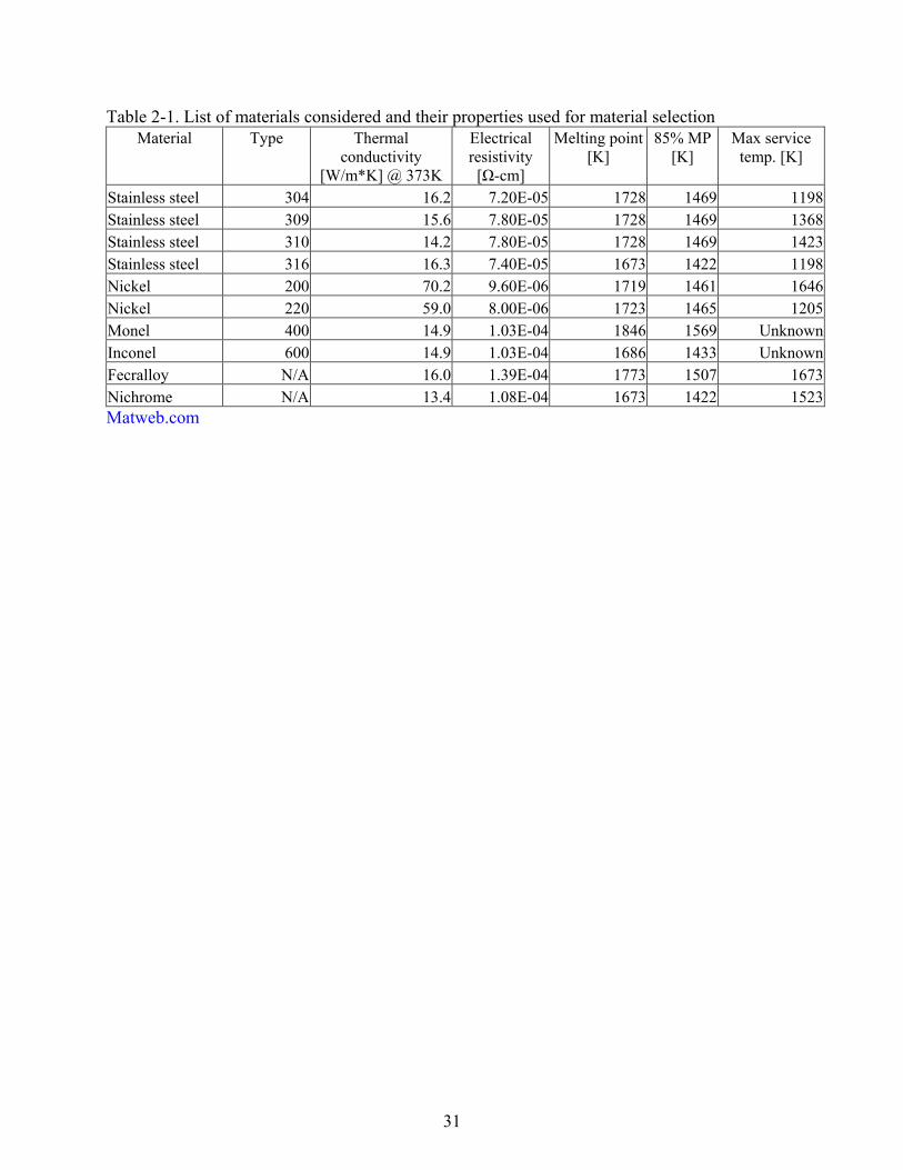
Several materials, listed in Table 2-1, were investigated for use in the heater. It can be seen
there are differences in electrical conductivity and maximum operating temperatures. These
properties, as well as cost, and availability were used as the selection criteria. Inconel and Monel
were removed from selection due to cost, and availability. Nickel and Fecralloy were eliminated
due to their unavailability in tube stock and other required sizes. Finally stainless steel 310 has
the highest operating temperature which was the reason it was chosen for this design. It has the
lowest cost, availability in tube stock and other forms that are required, good corrosive
resistance, and an acceptable electrical resistance.
30
Figure 2-1. Heater facility diagram with optional second stage heater. Second stage heater requires hydrogen or some other fuel and oxygen replenishment.
31
Table 2-1. List of materials considered and their properties used for material selection Material Type Thermal
conductivity [W/m*K] @ 373K
Electrical resistivity [Ω-cm]
Melting point [K]
85% MP [K]
Max service temp. [K]
Stainless steel 304 16.2 7.20E-05 1728 1469 1198 Stainless steel 309 15.6 7.80E-05 1728 1469 1368 Stainless steel 310 14.2 7.80E-05 1728 1469 1423 Stainless steel 316 16.3 7.40E-05 1673 1422 1198 Nickel 200 70.2 9.60E-06 1719 1461 1646 Nickel 220 59.0 8.00E-06 1723 1465 1205 Monel 400 14.9 1.03E-04 1846 1569 Unknown Inconel 600 14.9 1.03E-04 1686 1433 Unknown Fecralloy N/A 16.0 1.39E-04 1773 1507 1673 Nichrome N/A 13.4 1.08E-04 1673 1422 1523 Matweb.com
32
Insulation Sizing
Continuous operation minimization of the loss of heat requires insulation of all hot parts.
The insulation was sized using simulation data, computational analysis, and experimental data
from the prototype. The insulation materials chosen for the heater facility were Zircar alumina-
silica type AXL for use as solid semi cylinders and Zircar Type ASB-2300 blanket insulation;
both have a maximum service temperature of 1500K. The solid material was chosen because its
operating temperatures exceed that of the steel used, it is easily machined, relatively inexpensive,
and has high thermal and electrical resistances. The blanket was chosen for portions of the heater
where rigid insulation would be difficult to manufacture and install.
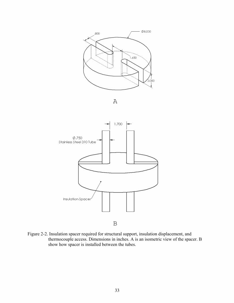
A semi-composite insulation structure is used in the current design. This semi-composite
structure is comprised of an air gap between the hot tubes and the insulation cylinder mentioned
to take advantage of the high thermal resistance of air. This setup requires the use of several
ceramic spacers that maintain proper displacement between the insulating cylinders and the hot
tubes and aid in the structural support of the hot tubes, which begin to lose rigidity at the high
operating temperatures. The spacers also allow an easy access point for the placement of
thermocouples which are required for safety monitoring of the facility and will be welded to the
steel. Finally, the spacers create a barrier between the air gaps of the large cylinders minimizing
natural convective flow and enhancing thermal resistance. Figure 2-2 shows these spacers and
how they are placed between each tube.
Since the material chosen has nearly identical thermal resistance as used in the Prototype,
discussed in the next section, similar heat transfer characteristics are expected for this new
facility. This performance includes minimizing heat loss enabling attainment of efficiencies of
nearly 90%. In addition, the outer surface temperature stayed below 473K while internal tube
temperatures were above 1300K.
33
Figure 2-2. Insulation spacer required for structural support, insulation displacement, and thermocouple access. Dimensions in inches. A is an isometric view of the spacer. B show how spacer is installed between the tubes.
34
Insulation Dimensions and Assembly
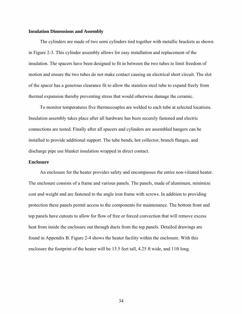
The cylinders are made of two semi cylinders tied together with metallic brackets as shown
in Figure 2-3. This cylinder assembly allows for easy installation and replacement of the
insulation. The spacers have been designed to fit in between the two tubes to limit freedom of
motion and ensure the two tubes do not make contact causing an electrical short circuit. The slot
of the spacer has a generous clearance fit to allow the stainless steel tube to expand freely from
thermal expansion thereby preventing stress that would otherwise damage the ceramic.
To monitor temperatures five thermocouples are welded to each tube at selected locations.
Insulation assembly takes place after all hardware has been securely fastened and electric
connections are tested. Finally after all spacers and cylinders are assembled hangers can be
installed to provide additional support. The tube bends, hot collector, branch flanges, and
discharge pipe use blanket insulation wrapped in direct contact.
Enclosure
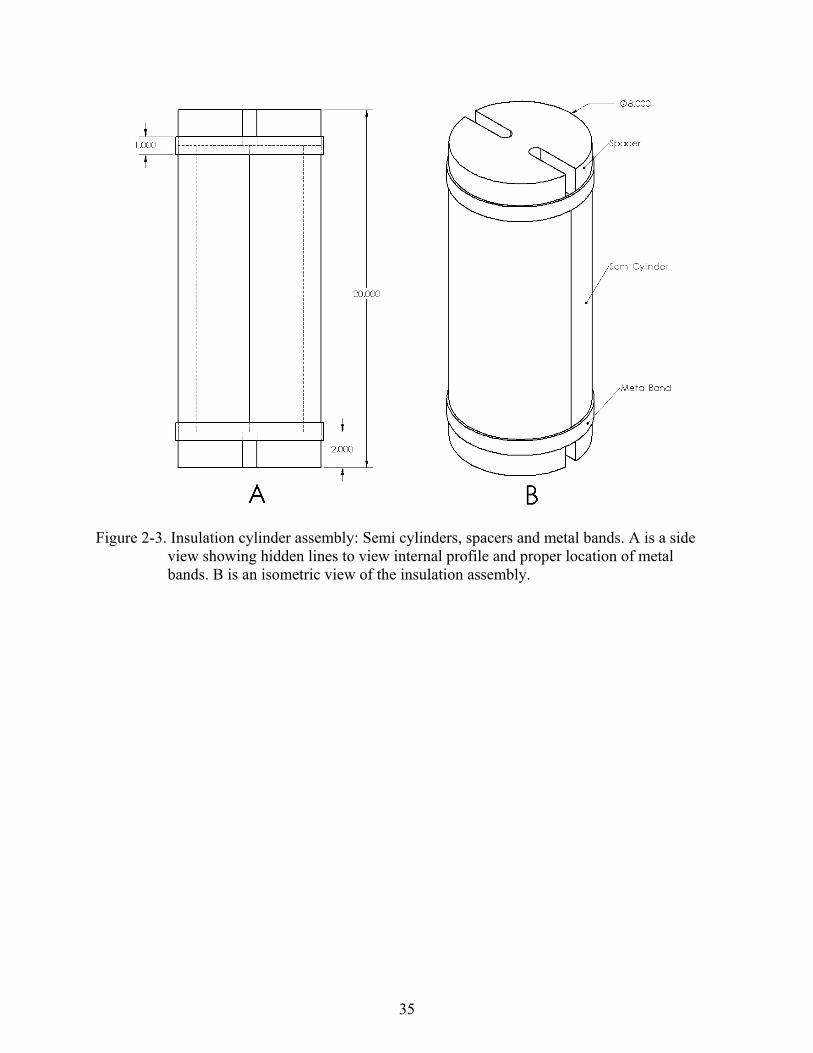
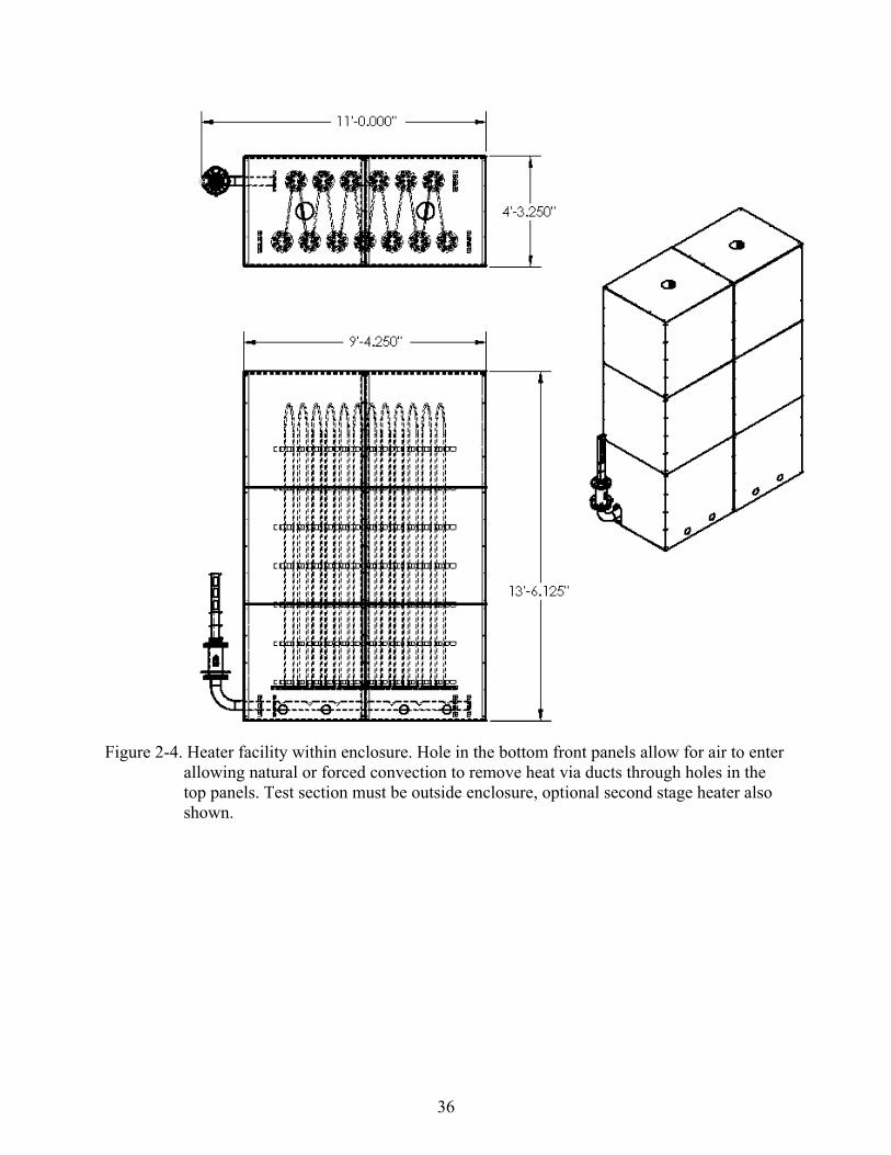
An enclosure for the heater provides safety and encompasses the entire non-vitiated heater.
The enclosure consists of a frame and various panels. The panels, made of aluminum, minimize
cost and weight and are fastened to the angle iron frame with screws. In addition to providing
protection these panels permit access to the components for maintenance. The bottom front and
top panels have cutouts to allow for flow of free or forced convection that will remove excess
heat from inside the enclosure out through ducts from the top panels. Detailed drawings are
found in Appendix B. Figure 2-4 shows the heater facility within the enclosure. With this
enclosure the footprint of the heater will be 13.5 feet tall, 4.25 ft wide, and 11ft long.
35
Figure 2-3. Insulation cylinder assembly: Semi cylinders, spacers and metal bands. A is a side view showing hidden lines to view internal profile and proper location of metal bands. B is an isometric view of the insulation assembly.
36
Figure 2-4. Heater facility within enclosure. Hole in the bottom front panels allow for air to enter allowing natural or forced convection to remove heat via ducts through holes in the top panels. Test section must be outside enclosure, optional second stage heater also shown.

37
CHAPTER 3 PROTOTYPE
Setup
The prototype is a scaled down model of the main facility with a ratio of 1:25 mass flow
rate and tube dimensions scaled to maintain equivalent Reynolds numbers. The prototype was
used to test the feasibility and performance of such a heater. The entire heater assembly was
constructed of stainless steel 310. The heater consists of an electric resistance heating element,
inlet and exit flanges, insulation, and mount. Detail drawings of this system and its components
are found in Appendix C. A total of six K-type thermocouples were installed to monitor the steel
tube temperature and a seventh used to measure the exit air stagnation temperature.
Thermocouple locations are measured from the inlet and are given here in percentage of the
overall length of 144 inches; 30%, 45%, 60%, 80%, 95% and 100%. Thermocouple locations are
clearly marked in Figure 3-1.
Air is supplied from a large storage vessel and controlled via a pressure regulator with
Figure 3-2 showing the air flow circuit of the experiment. Flow rates were measured using an
inline float flow meter downstream of the regulator. Electric power was supplied by a DCR-
A250 transformer whose power rating was determined by the maximum voltage and current that
could be produced, where the maximum achievable power was 9.4 kW. From the Reynolds
number’s relationship to heat transfer characteristics analysis of this heater is compared to the
design operating conditions of the main facility where the design operating conditions occurs at a
Reynolds number of 93,400.
Insulation Sizing
Insulation was designed and applied to the heater for safety and to improve performance.
The insulation used was a Zircar Type ASB-2300 blanket, which has a maximum operating
38
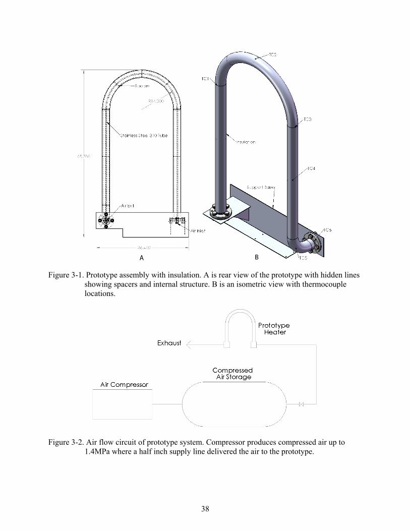
Figure 3-1. Prototype assembly with insulation. A is rear view of the prototype with hidden lines showing spacers and internal structure. B is an isometric view with thermocouple locations.
Figure 3-2. Air flow circuit of prototype system. Compressor produces compressed air up to 1.4MPa where a half inch supply line delivered the air to the prototype.
39
temperature of 1500K, and was lined on the inside of a three inch galvanized steel air-
conditioning ducting. The air conditioning duct material was used because it acted as an
exoskeleton for the insulation to enable creation of a uniform air gap with blanket material.
Sizing of the insulation was developed from results obtained from computational heat
transfer analysis comparing the effects insulation in direct contact to the heater tube with varying
thicknesses and composite insulation of different inner diameters and thicknesses. The heat
transfer analysis was based on the thermal resistance concept of a multilayer radial medium.
Equations are taken from Cengel.14 The steady state heat conduction equation is the following
Total
TQ
R
Total i Insulation NC
i
R R R R
where RTotal is the total resistance of the medium, Q is the rate of heat transfer, and T is the
difference of the gas temperature inside the cylinder and the ambient temperature. Thermal
contact resistances were neglected as a conservative approach in all heat transfer calculations.
The equations governing the resistances are as follows.
1NC
NC NC
Rh A
ln( / )
2Insulation
Insulation
OD IDR
L k
and for the composite insulation ln( / ) ln( / )
2 2Inuslation
Air Insulation
ID TD OD IDR
L k L k
c
Nu kh
L
2A r L where OD and ID are the inner and outer diameters of the insulation and TD is the outer diameter
of the heating tube. L is the length of the insulation where in this analysis a unit length scale is
used, h is the convection heat transfer coefficient, k is the thermal conductivity of a material, L is
40
the length of the cylinder, A is the area corresponding to the surface boundary in contact with the
fluid with r the outer radius of the insulation. Nu is the Nusselt number of the fluid, and Lc is the
characteristic length of the geometry, in this case the diameter. The Nusselt number is dependent
on the motion of the fluid and the geometry associated with it. The Nusselt number in this case is
based on natural convection around a cylindrical body, and is defined as follows
1
6
89 27
16
0.387 Pr0.825
0.4921
Pr
r
NC
GNu
3inf
2
1 c
surface
r
Tg L
TG
This Nu number equation is valid when the diameter of the cylinder meets the following criteria
1
4
35
r
LD
G
Here Gr is the Grashof number, g is gravity, υ is the kinematic viscosity of the fluid, and Pr is the
Prandtl number, which for standard air has the value of 0.73.
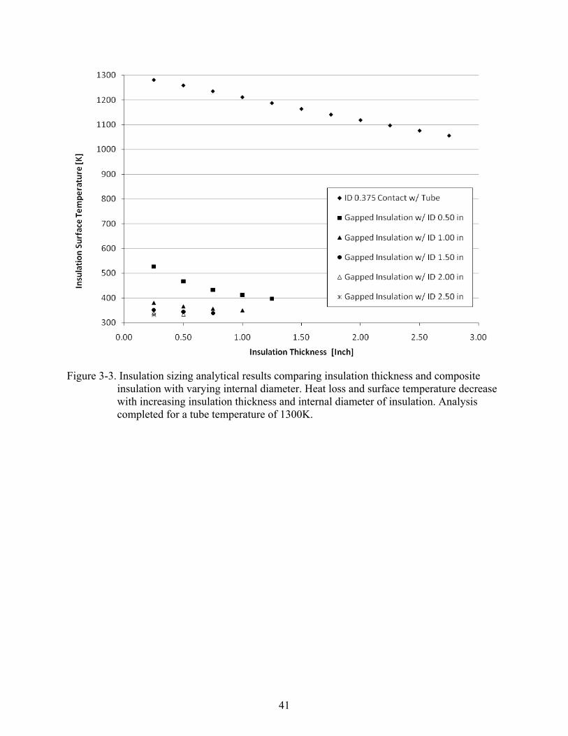
Heat transfer analysis results of the insulation are given in Figure 3-3. The composite
gapped insulation provides significantly better performance over that insulation that is in contact
with the tube. As the gap or inner diameter of the insulation increased to 2.5 inches the effect of
insulation thickness became negligible. Therefore insulation with inner diameter of 2.5 inches
and thickness of 0.25 inch was used due to a limitation of a 3inch OD from heater geometry and
negligible gain arises from any increase in ID or thickness.
Spacers made of hard insulation were used to ensure the air gap between the insulation and
the tube was maintained and made the entire structure more stable and supportive. The spacers
and ducting material act as a supportive frame for the stainless steel tube that becomes less rigid
at the high operating temperatures.
41
Figure 3-3. Insulation sizing analytical results comparing insulation thickness and composite insulation with varying internal diameter. Heat loss and surface temperature decrease with increasing insulation thickness and internal diameter of insulation. Analysis completed for a tube temperature of 1300K.
42
Experimental Results and Conclusions
A range of Reynolds numbers was tested from 18,860 to 130,076. From the theoretical
analysis, under the condition of 100% efficiency for a mass flow rate of 0.0208kg/s,
corresponding to Re = 93,400, the power required is 25.8 W. With the power supply used the
desired temperature could be attained at only Re = 70,000 based on the supply stagnation
temperature of 300K. Tests achieving the desired temperature were successfully completed for
Re up to 42,030 due to inefficiencies of the system.
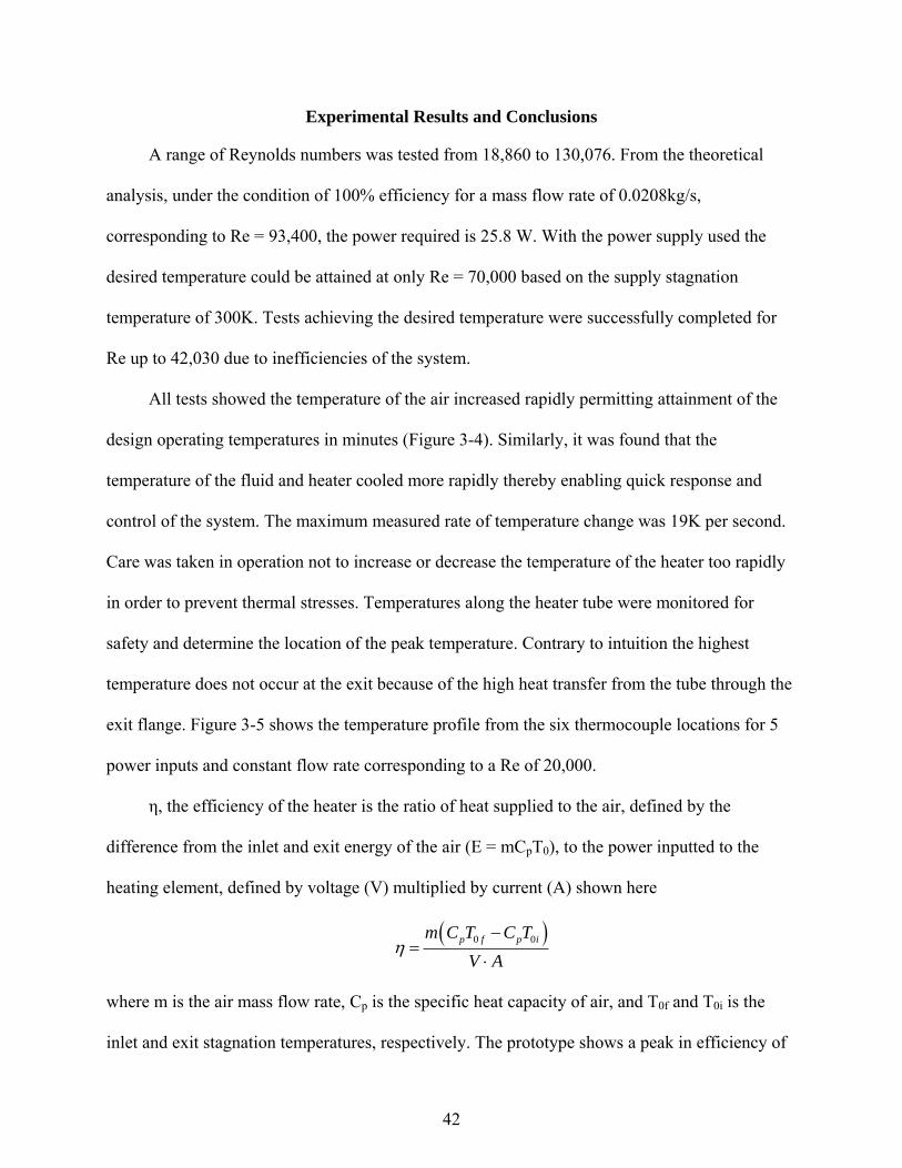
All tests showed the temperature of the air increased rapidly permitting attainment of the
design operating temperatures in minutes (Figure 3-4). Similarly, it was found that the
temperature of the fluid and heater cooled more rapidly thereby enabling quick response and
control of the system. The maximum measured rate of temperature change was 19K per second.
Care was taken in operation not to increase or decrease the temperature of the heater too rapidly
in order to prevent thermal stresses. Temperatures along the heater tube were monitored for
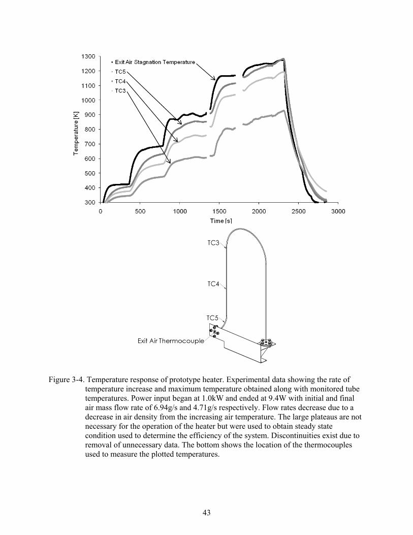
safety and determine the location of the peak temperature. Contrary to intuition the highest
temperature does not occur at the exit because of the high heat transfer from the tube through the
exit flange. Figure 3-5 shows the temperature profile from the six thermocouple locations for 5
power inputs and constant flow rate corresponding to a Re of 20,000.
η, the efficiency of the heater is the ratio of heat supplied to the air, defined by the
difference from the inlet and exit energy of the air (E = mCpT0), to the power inputted to the
heating element, defined by voltage (V) multiplied by current (A) shown here
0 0p f p im C T C T
V A
where m is the air mass flow rate, Cp is the specific heat capacity of air, and T0f and T0i is the
inlet and exit stagnation temperatures, respectively. The prototype shows a peak in efficiency of
43
Figure 3-4. Temperature response of prototype heater. Experimental data showing the rate of temperature increase and maximum temperature obtained along with monitored tube temperatures. Power input began at 1.0kW and ended at 9.4W with initial and final air mass flow rate of 6.94g/s and 4.71g/s respectively. Flow rates decrease due to a decrease in air density from the increasing air temperature. The large plateaus are not necessary for the operation of the heater but were used to obtain steady state condition used to determine the efficiency of the system. Discontinuities exist due to removal of unnecessary data. The bottom shows the location of the thermocouples used to measure the plotted temperatures.
44
Figure 3-5. Prototype heater tube temperature distribution. Monitored steady-state tube temperatures for flow with Re = 20,000 at five different power inputs. Total length of the tube is 144 inches; location is given in percentage of this length with 100% corresponding to the exit. Peak temperature does not occur at the exit due to high heat loss from exit flange. Bottom shows the specific location of the thermocouples on the heater element.
45
90% at a Reynolds number of 85,000. Considering the efficiency’s dependence on both
Reynolds number and exit air temperature the efficiency at design condition has been estimated
to be 80%. This could be done since the magnitude and rate of change of efficiency is dependent
on the Reynolds number in addition to a linear dependence on exit air temperature as seen in
Figure 3-6. The efficiency increases with increasing Reynolds number to 85,000 then begins to
decrease showing there is an optimum operating range of Reynolds numbers, and this facility has
been designed to operate in this range. Figure 3-7 shows the required power to mass flow rate
ratio required to obtain specific values of the exit air stagnation temperature. This means
significantly more power for the same flow rate is required to increase the air stagnation
temperature at high temperatures than it does at low temperature.
In conclusion this heater is easily controlled and operated, and is feasible for use in a large
scale non-vitiated facility for the given design condition provided sufficient power is available.
The quick response of the system enables experiments that require fast transient conditions.
46
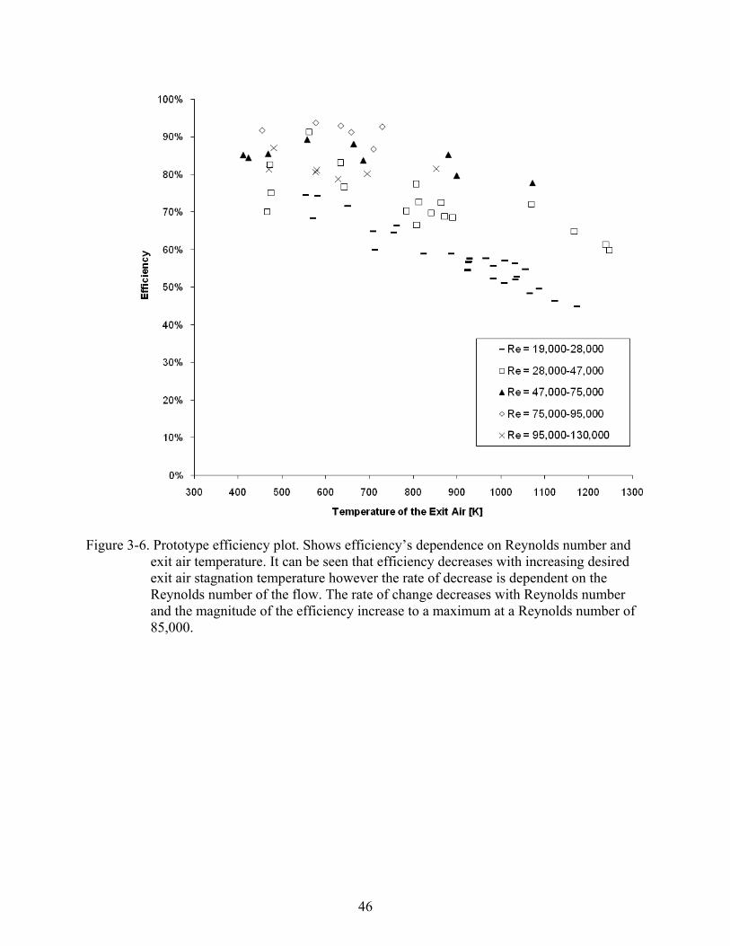
Figure 3-6. Prototype efficiency plot. Shows efficiency’s dependence on Reynolds number and
exit air temperature. It can be seen that efficiency decreases with increasing desired exit air stagnation temperature however the rate of decrease is dependent on the Reynolds number of the flow. The rate of change decreases with Reynolds number and the magnitude of the efficiency increase to a maximum at a Reynolds number of 85,000.
47
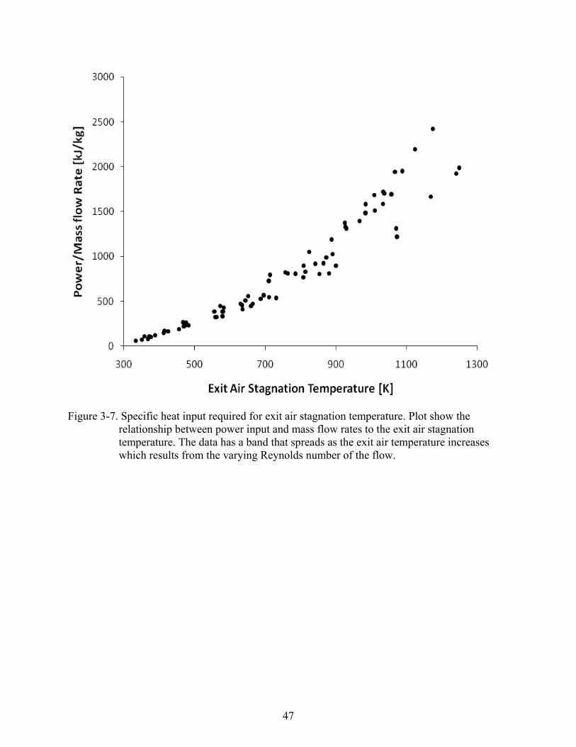
Figure 3-7. Specific heat input required for exit air stagnation temperature. Plot show the relationship between power input and mass flow rates to the exit air stagnation temperature. The data has a band that spreads as the exit air temperature increases which results from the varying Reynolds number of the flow.

48
CHAPTER 4 SECOND STAGE HEATER DESIGN
The second stage heater is an additional, although optional, component and its use creates
vitiated air flow, via hydrogen combustion, to send to the test section. The main purpose of its
inclusion is to enhance the temperature capabilities of the non-vitiated system as well as to
provide the ability of back-to-back testing under same day conditions using both vitiated and
non-vitiated flow through a test section for comparison on the effects of the vitiated flow. This is
useful in determining correlations from data already obtained from vitiated tests to how the data
relates to real conditions. The heater design comprising of a stainless steel 310 cylinder with
appropriate flanges for assembly, high temperature Zircar ceramic insulation, flame holder,
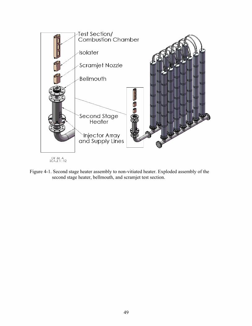
parallel series of four fuel injectors, and a plasma torch. Figure 4-1 shows the heater and test
section assembly to the non vitiated heater and Figure 4-2 is a detail of the heater assembly.
Detailed part and assembly drawings of the heater are found in Appendix D.
Design Parameters
The second stage heater utilizes hydrogen as the working fluid. This fuel was chosen due
to its high energy content giving the highest possible temperatures, and minimal combustion
products. Although this system is designed for hydrogen, other fuels may be used as is or with
minor modifications. One such modification would be the type of injector used, due to a change
in required flow rate and mixing characteristics.
The design specification was to provide test air stagnation temperatures of 1800K to cover
the entire range of the non-vitiated heater and enable tests of up Mach 6. Several factors were
considered in this design, such as proper material selection and geometry sizing and design. A
secondary objective was to minimize the size of this heater for ease of installation and removal
and to reduce cost.
49
Figure 4-1. Second stage heater assembly to non-vitiated heater. Exploded assembly of the second stage heater, bellmouth, and scramjet test section.

50
Figure 4-2. Second stage heater assembly drawing. A shows the second stage heater assembly without plasma torch. B is a section view showing internal components and layout.
51
Heater Design
Sizing of the heater length and positioning of the injectors and flame holder was based on
the combustion and mixing characteristics of the fuel air mixture. Proper time for fuel air mixing
and complete combustion determined the distance between the injectors and the flame holder and
the flame holder and the exit, respectively. Temperatures are monitored on the exterior and
interior portions of the heater via the installation of thermocouples. This is required to control
temperature of the test conditions and maintain all the components at safe temperatures.
Plasma Torch
Ignition of the fuel is by means of a plasma torch. This was chosen because, unlike spark
plugs and other ignition sources, which must be in the flow, the torch can project plasma into the
combustion chamber. This prevents igniter contact with the hot fluid, preventing damage that
would occur during continuous exposure to the hot gas for long periods of time.
A DC powered torch was chosen as the igniter because of its capacity to produce a
continuous stream of plasma whole using low flow rates of either air or nitrogen as the working
fluids. For a given flow rate of fuel the DC torch produces a higher maximum mean intensity of
the radical hydroxyl (OH) while using less power in comparison to an AC powered torch. A
higher maximum mean intensity of OH means the plasma has created a greater number of OH
radicals which are required for chain branching reactions to produce and continue combustion.
The AC torch is limited to bursts of plasma at specific frequencies and requires a higher flow
rate of only air to produce characteristics similar to that of a DC torch.15
Cylinder and Insulation Sizing
The sizing of the cylinder and the insulation had to be completed simultaneously due to the
dimensional dependence one has on the other. Insulation of this heater is not only necessary to
minimize heat loss but also to protect the heater components from melting. An internal insulating
52
cylinder made of Zircar Alumina Type ALC is used with its outer walls in contact with the inner
walls of the steel cylinder housing. The insulation has a maximum service temperature of 1825K
and is sized to have an inner diameter smaller than that of the supply pipe in order to throttle the
fluid, decreasing the static temperature of the fluid, and to minimize throttling required
downstream at the bellmouth. Sizing was based on a compromise between the outer cylinder
diameter influencing flange design and pipe size availability, maximum steel operating
temperature, and heat loss.
The heat transfer analysis is based on the following computational analysis and associated
assumptions. All calculations were made in the radial coordinate system with a conservative
assumption of an inner cylinder uniform static temperature of 1800K. Two models for insulation
were used, a standard single cylinder and a composite insulation that utilized an air gap. Forced
Turbulent Convection was modeled inside the chamber, conduction for the insulation and steel
material, and natural convection on the outer surface temperature of the steel cylinder.
The heat transfer analysis was conducted similarly to the method used in the sizing of the
prototype insulation with the addition of forced convective heat transfer. The basic equations
governing the analysis are
Total
TQ
R
1
Gas
Gas Gas
Rh A
1NC
NC NC
Rh A
3 2ln( / )
2SS
SS
r rR
L k
2 1ln( / )
2Insulation
Insulation
r rR
L k
and in the case of the composite insulation
1 1 1 1 2 1ln( / ) ln( / ) ln( / )
2 2 2
A B BInuslation
Insulation Air Insulation
r r r r r rR
L k L k L k
The Nusselt number required for the determination of the convective heat transfer coefficient of
the internal forced convection is obtained from
53
4 1
5 3_ 0.027Re PrTurbulent GasNu
which corresponds to flows with Re>10,000. The Nusselt number that corresponds to natural
convection for large cylinders is defined as
1
6
89 27
16
0.387 Pr0.825
0.4921
Pr
r
NC
GNu
equations are from Cengal.14
Sizing was chosen giving a maximum temperature of 900K for the stainless steel cylinder
corresponding to a factor of safety of 1.6 with respect to maximum service temperature. In
addition to the insulation, metal tubing is coiled around the cylinder to water cool the steel
allowing the use of higher stagnation temperatures when required, as well as additional safety.
With this addition the maximum steel temperature will be within 10K of the maximum water
temperature and the total heat loss will increase by a factor of 1.65. The insulation (Figure 4-3)
was designed to be assembled in two pieces, a removable section and a permanent section. The
reason for this was to enable removal of the upper section to gain access to the flame holder for
easy installation and removal.
Fuel Injectors
The hydrogen fuel injectors were designed to achieve air stagnation temperatures up to
1800K. The design considerations include air flow rate, maximum supply pressure, mixing
performance, and fuel mass flow requirement. From combustion and stoichiometric fuel analysis,
for the design air mass flow rate of 250g/s, hydrogen mass flow rates up to 6.04g/s are required.
Combustion analysis was based on the following reaction

54
Figure 4-3. Insulation assembly detail drawing. Shows complex geometry required for assembly and insertion of flame holder, injectors, and plasma. A is an exploded view of the insulation assembly. B shows the assembled insulation. C is a section view of insulation featuring insulation thickness and coupling geometry.
55
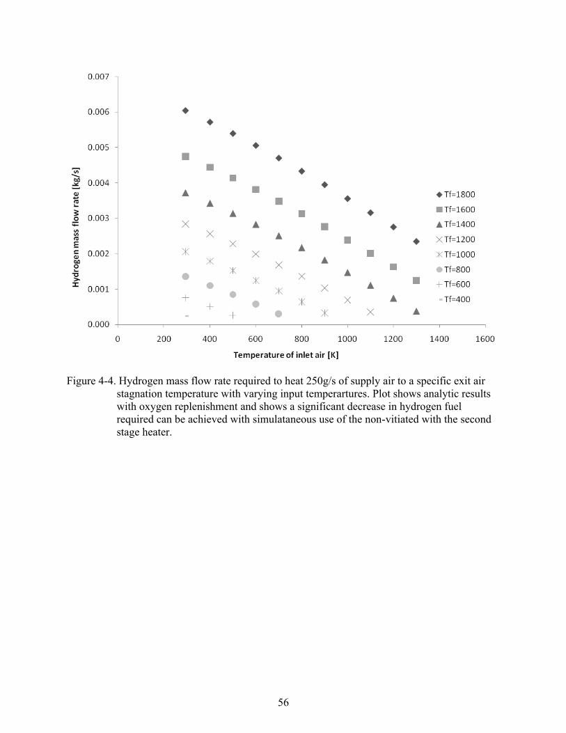
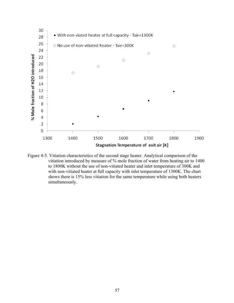
Figure 4-4 shows the relationship of the hydrogen mass flow rate required to achieve specific
exit air stagnation temperatures for various inlet air temperatures. Figure 4-5 compares the
vitiation that occurs by heating air to 1400 to1800K during operation of the second stage heater
with and without simultaneous use of the non-vitiated heater. Vitiation is decreased by 15% with
simultaneous use of the non-vitiated heater. Combustion analysis required fluid properties of air
at elevated temperatures, including Prandtl number, thermal conductivity, and viscosity which
were obtained from Ibele.16 Combustion analysis as well as lean and rich flammability limits of
hydrogen was obtained from Turns.17 Oxygen replenishment is needed due to the amount of
oxygen required to fully burn the fuel and ensure the air composition has the proper oxygen
percentage. This replenishment/enrichment occurs in the air supply line upstream of the heaters.
To supply the fuel a total of four injectors, detailed in Figure 4-6, were decided upon with
each injector having five nozzles. Three of the orifices are oriented to inject the fuel vertically
while two are offset from the vertical by an angle of 45 degrees to provide improved mixing in
comparison to the case where all five nozzles are oriented vertically. The performance of this
design has been verified with the use of COSMOS CFD software (Figures 4-7 and 4-8) for
various required flow rates. Figure 4-8 specifically compares the performance of the injector
with all the nozzles oriented vertically with that of the chosen design. Simulation conditions for
of all figures involve 250g/s of supply air plus the additional mass flow rate of oxygen mass. The
figure legend shows the hydrogen mass fraction in the flow and the scale chosen such that the
lowest (0.00404) and highest (0.06875) values correspond to the lean and rich flame limits17 of
hydrogen, respectively, thus visualizing the possible flame regions. The horizontal planar cuts
shown are at half inch intervals.
The nozzle diameter was sized to ensure sonic flow of the hydrogen gas over a large range
of design requirements with reasonable required pressures to produce the maximum needed mass
56
Figure 4-4. Hydrogen mass flow rate required to heat 250g/s of supply air to a specific exit air stagnation temperature with varying input temperartures. Plot shows analytic results with oxygen replenishment and shows a significant decrease in hydrogen fuel required can be achieved with simulataneous use of the non-vitiated with the second stage heater.
57
Figure 4-5. Vitiation characteristics of the second stage heater. Analytical comparison of the vitiation introduced by measure of % mole fraction of water from heating air to 1400 to 1800K without the use of non-vitiated heater and inlet temperature of 300K and with non-vitiated heater at full capacity with inlet temperature of 1300K. The chart shows there is 15% less vitiation for the same temperature while using both heaters simultaneously.

58
Figure 4-6. Fuel injector detail drawing. A shows top view with injector end views showing injector dimensions and nozzle orientation. B shows side view of the injector. C is a detail section showing nozzle size and layout.

59
A B
C D
Figure 4-7. Hydrogen mixing characteristics of two flow rates. Mixing for hydrogen mass flow rates of 1.24g/s in A and B and 3.23g/s in C and D with flow rates corresponding to temperature increases of 300K and 700K respectively. A and C show horizontal slices of the mixing profile at half inch intervals. B and D show a vertical slice of the injector centerline.

60
A B
C D
Figure 4-8. Fuel injector design mixing comparison. Hydrogen mass flow rate of 6.04 g/s for a temperature increase of 1500K. Injector design A and B is compared to design with all nozzles oriented vertically C and D. Mixing of the chosen injector design is faster and more distributed.
61
flow rate. Operating at the sonic condition enables easy control of the flow rates due to the mass
flow rate dependence only in the difference of combustion chamber pressure and the hydrogen
injector pressure.
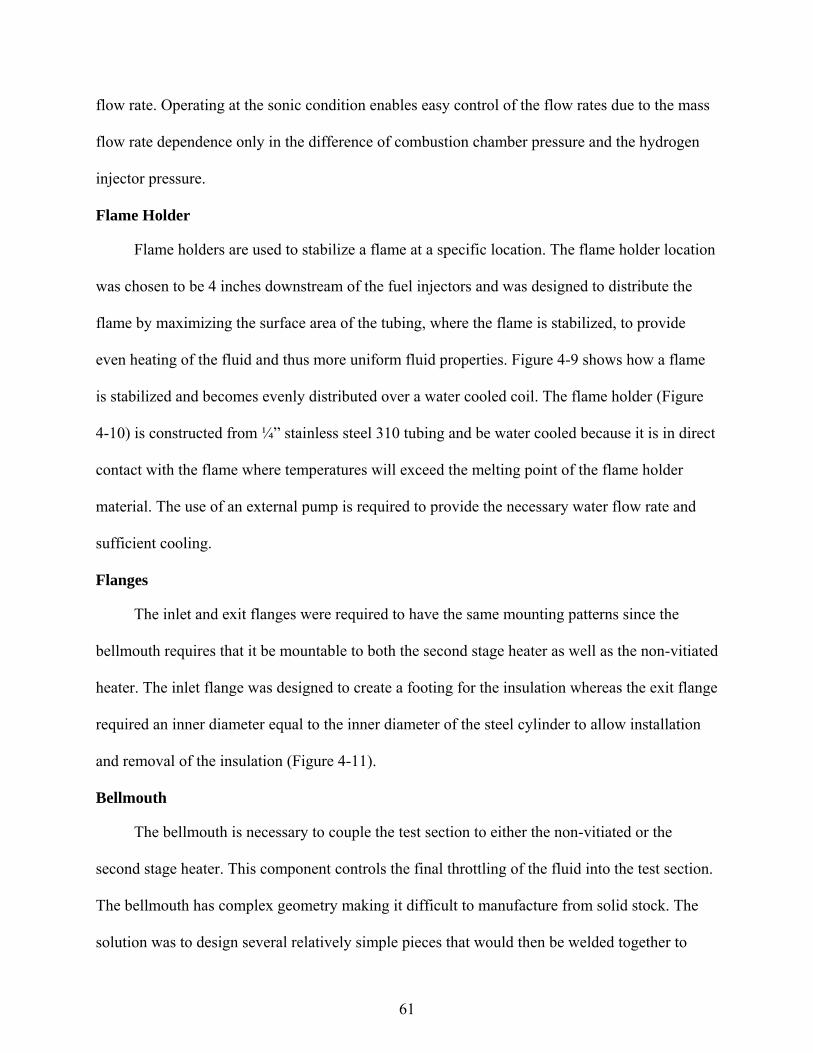
Flame Holder
Flame holders are used to stabilize a flame at a specific location. The flame holder location
was chosen to be 4 inches downstream of the fuel injectors and was designed to distribute the
flame by maximizing the surface area of the tubing, where the flame is stabilized, to provide
even heating of the fluid and thus more uniform fluid properties. Figure 4-9 shows how a flame
is stabilized and becomes evenly distributed over a water cooled coil. The flame holder (Figure
4-10) is constructed from ¼” stainless steel 310 tubing and be water cooled because it is in direct
contact with the flame where temperatures will exceed the melting point of the flame holder
material. The use of an external pump is required to provide the necessary water flow rate and
sufficient cooling.
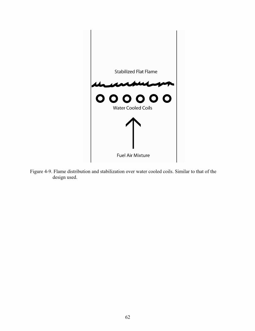
Flanges
The inlet and exit flanges were required to have the same mounting patterns since the
bellmouth requires that it be mountable to both the second stage heater as well as the non-vitiated
heater. The inlet flange was designed to create a footing for the insulation whereas the exit flange
required an inner diameter equal to the inner diameter of the steel cylinder to allow installation
and removal of the insulation (Figure 4-11).
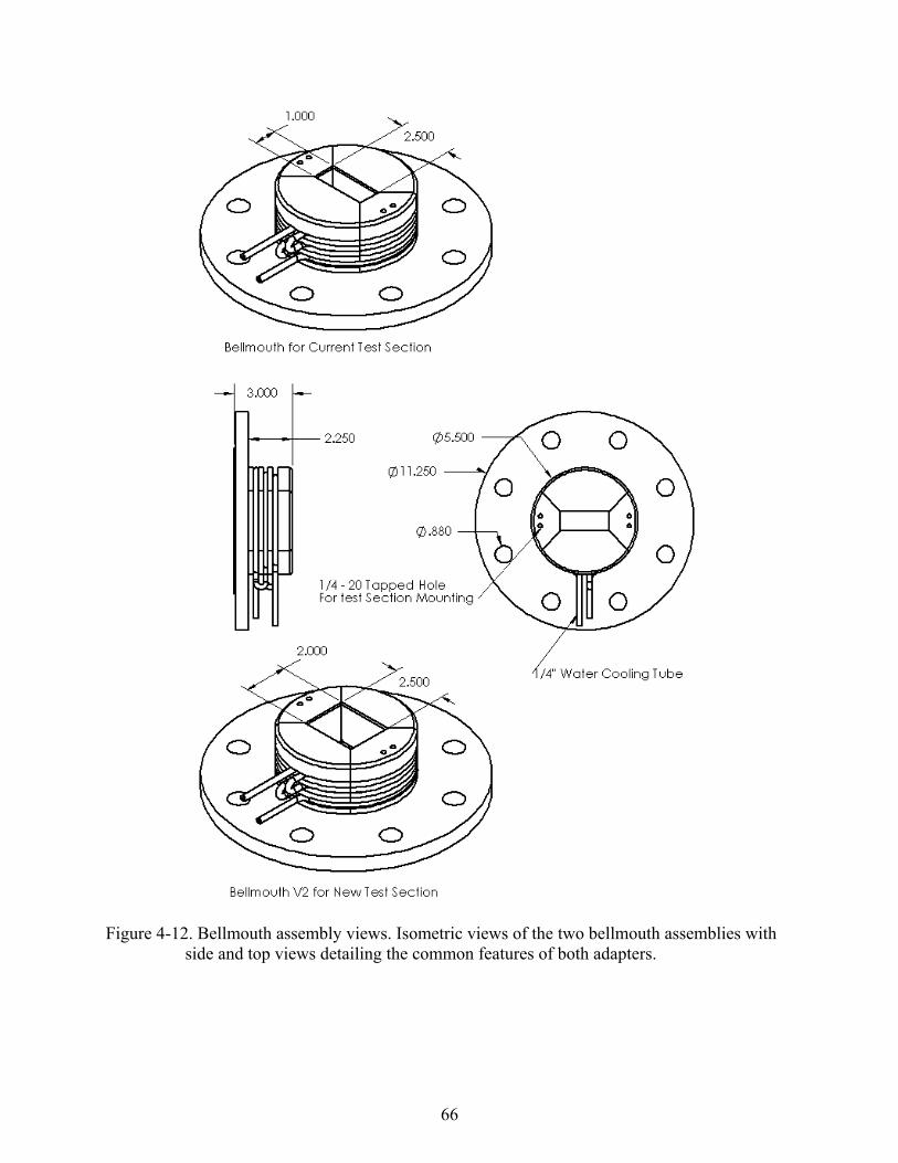
Bellmouth
The bellmouth is necessary to couple the test section to either the non-vitiated or the
second stage heater. This component controls the final throttling of the fluid into the test section.
The bellmouth has complex geometry making it difficult to manufacture from solid stock. The
solution was to design several relatively simple pieces that would then be welded together to
62
Figure 4-9. Flame distribution and stabilization over water cooled coils. Similar to that of the design used.

63
Figure 4-10. Flame holder detail drawing. Top view shows complex geometry to achieve maximum flame surface area. Water inlet and exit ports shown on bottom with tube dimensions.
64
Figure 4-11. Second stage heater inlet and exit flanges. Common dimensions not shown twice.

65
form the bellmouth. Two models have been developed, the first to adapt to the current test
section used and a second for a larger test section that will be manufactured.
Temperature control is important due to the high stagnation temperature to which the
bellmouth (Figure 4-12) is exposed to. To prevent overheating the internal components are
insulated with moldable insulation to a thickness of ¼” and be water cooled. There are three
grooves for placement of the water cooling piping in the bell mouth. An optional configuration
has a spiral groove with varying depth to match the inner profile of the bellmouth so that a tube
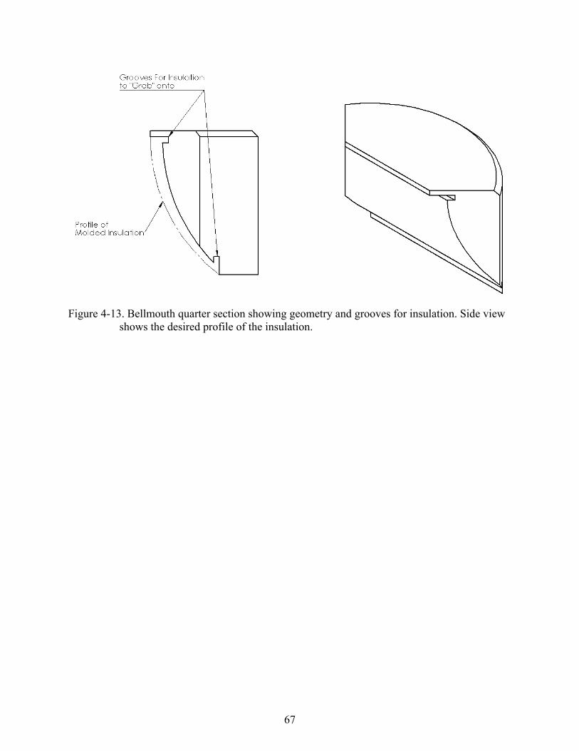
can be coiled around the bellmouth without discontinuities. Insulation grooves (Figure 4-13), are
necessary so that the moldable insulation, installed after assembly, has a place to seat and be held
in place. The insulation will be molded to provide a smooth transition from the second stage
heater insulation to the test section. Detailed drawings of the bellmouth are found in Appendix E.
66
Figure 4-12. Bellmouth assembly views. Isometric views of the two bellmouth assemblies with side and top views detailing the common features of both adapters.
67
Figure 4-13. Bellmouth quarter section showing geometry and grooves for insulation. Side view shows the desired profile of the insulation.
68
CHAPTER 5 CONCLUSIONS
This work found that this design of a non-vitiated heater ground test facility is feasible and
practical for use in supersonic combustion testing. The facility is required to produce air
stagnation temperatures of 1300K. A prototype was built and tested over a range of Reynolds
number showed that the heater is capable of heating air to this temperature under continuous
operation. Specifically, the desired results were obtained at a Reynolds number of 42,000. The
heater is very effective at heating air quickly and efficiently. The rapid response of the heater to
heat up or cool down allows experiments requiring fast transient test conditions to be performed.
Efficiencies of the heater ranged from 50 to 90% and were found to depend on the Reynolds
number of the air. The peak efficiency occurred at a Reynolds number of 85,000 and therefore
the heater facility has been designed to operate in this range.
A second stage heater was designed to supplement the non-vitiating heater. With this
addition vitiated air and non-vitiated air tests could be performed and compared to develop
correlations between both types of experimental results which can be used to better interpret data
obtained under vitiated conditions. This heater enhances the non-vitiated heater providing the
capacity to obtain Mach numbers up to 6 independently or with minimal vitiation when the two
systems are operated simultaneously.

69
APPENDIX A NON-VITIATED HEATER DRAWINGS
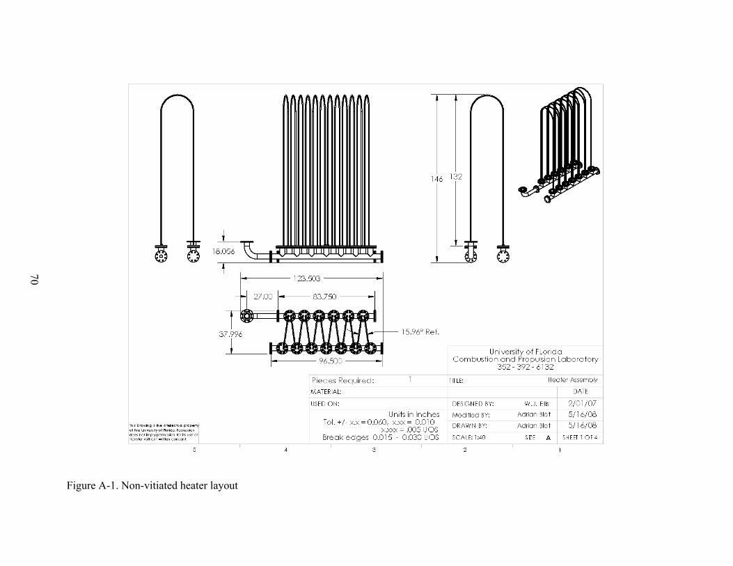
70
Figure A-1. Non-vitiated heater layout
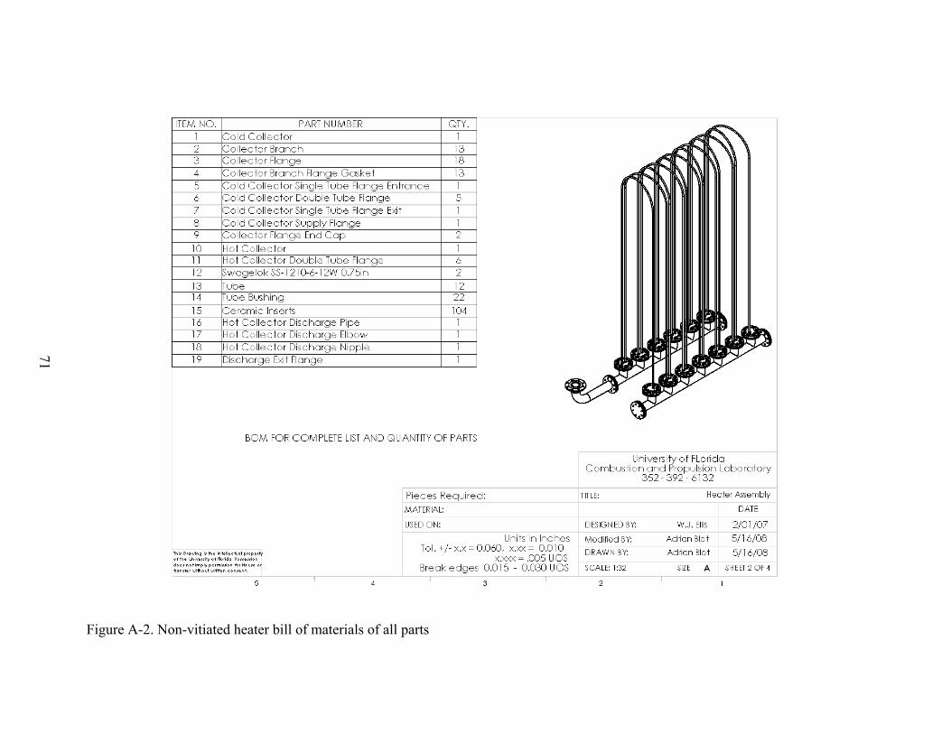
71
Figure A-2. Non-vitiated heater bill of materials of all parts
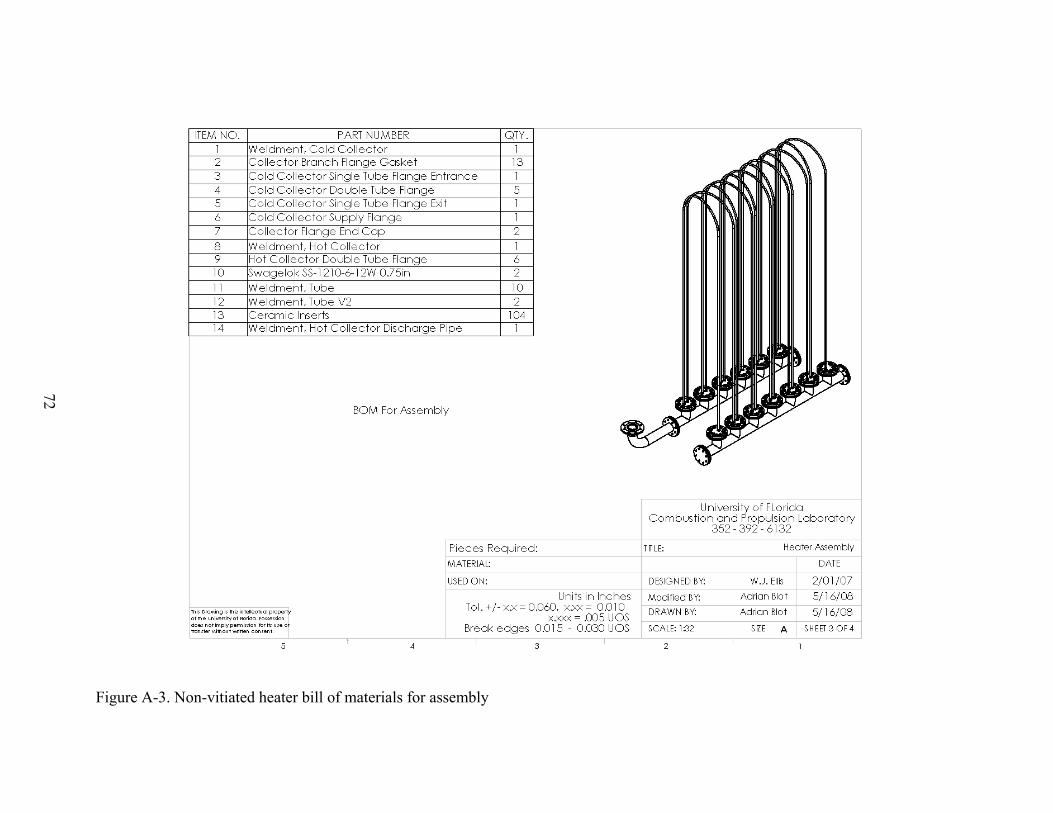
72
Figure A-3. Non-vitiated heater bill of materials for assembly

73
Figure A-4. Collector flange mechanical drawing
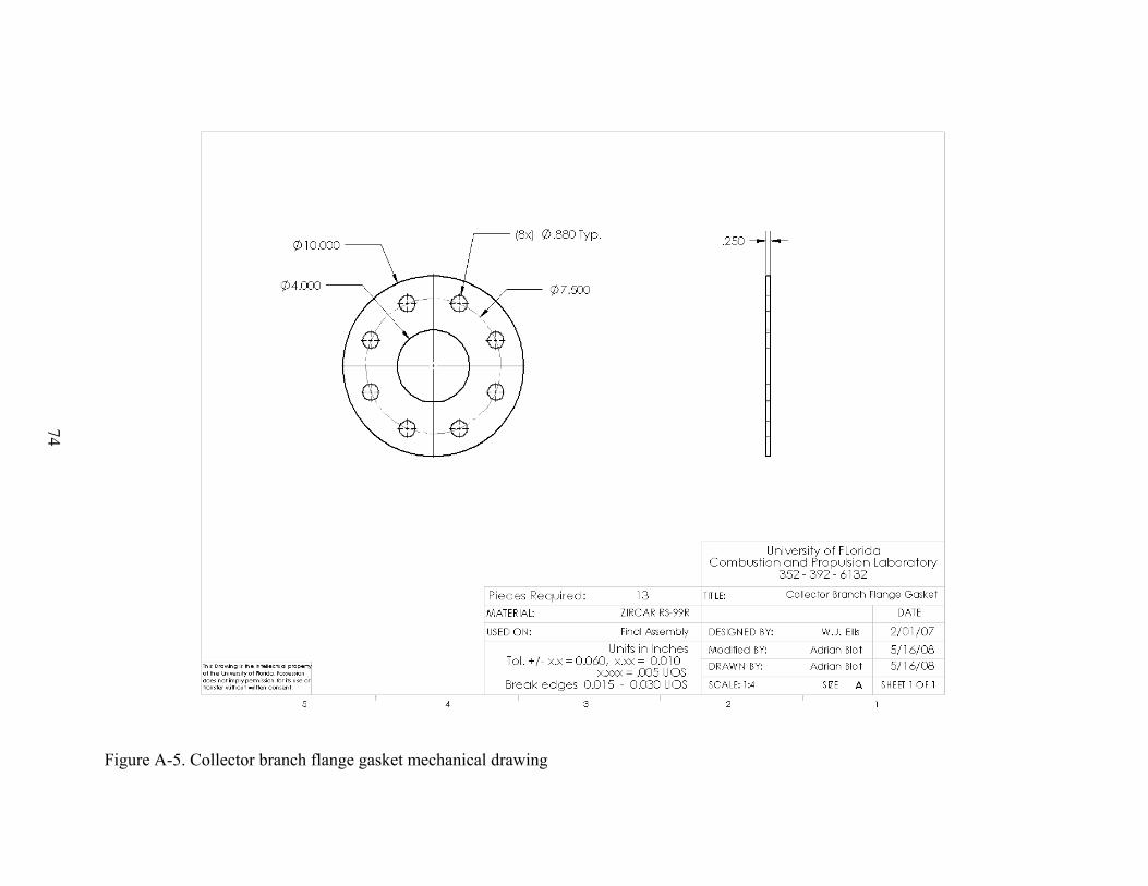
74
Figure A-5. Collector branch flange gasket mechanical drawing
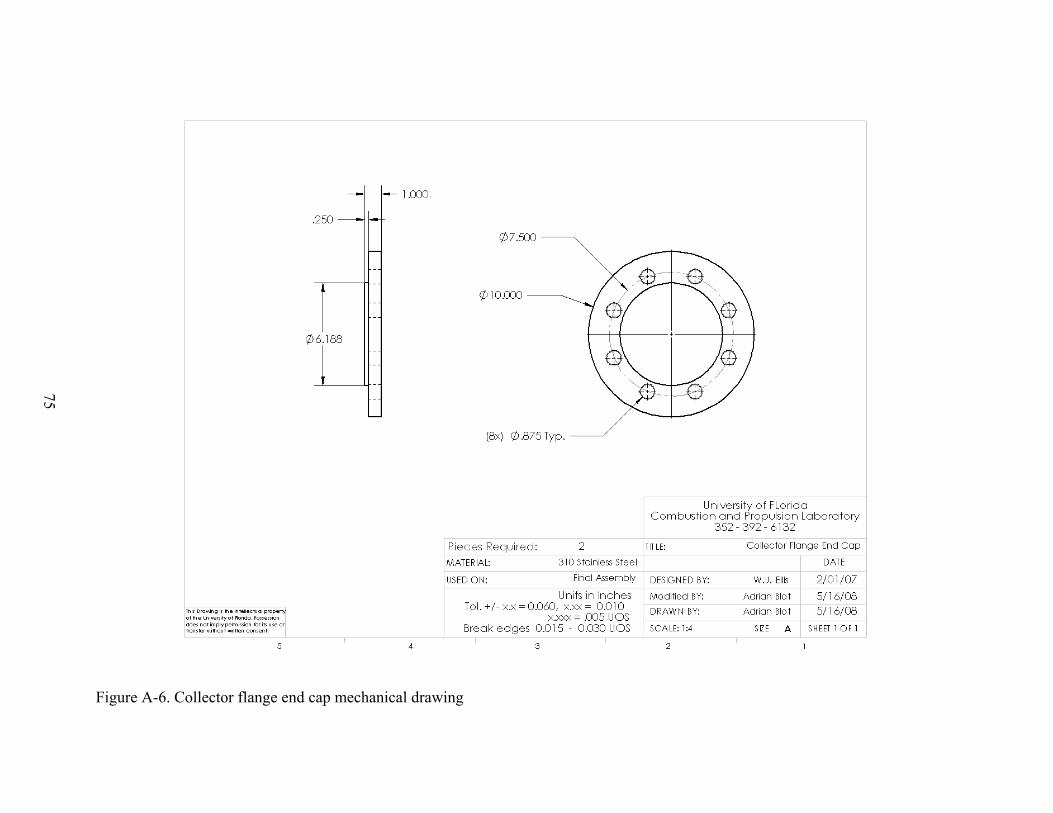
75
Figure A-6. Collector flange end cap mechanical drawing
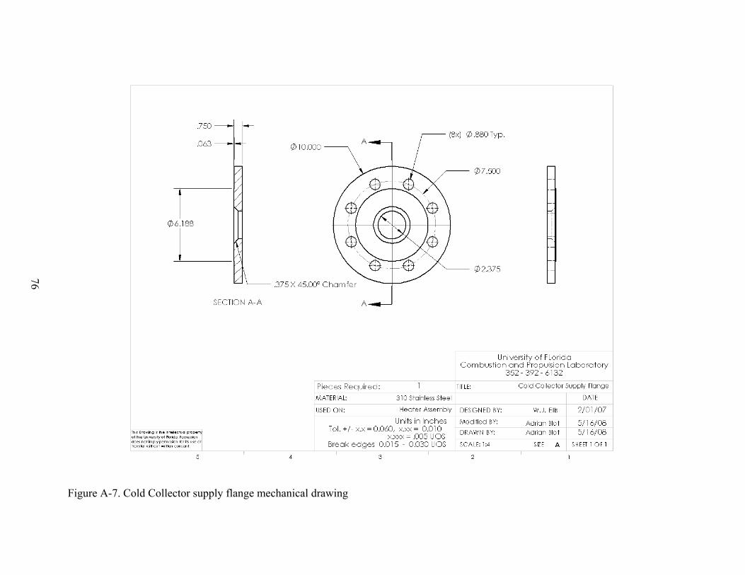
76
Figure A-7. Cold Collector supply flange mechanical drawing
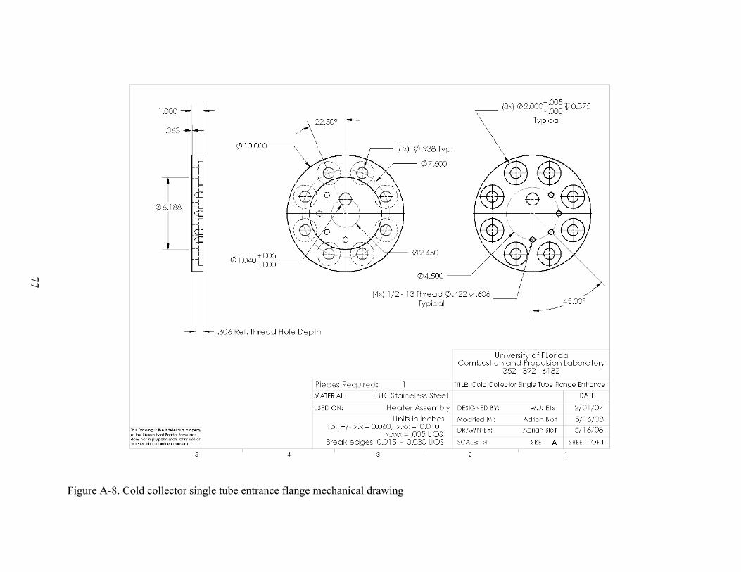
77
Figure A-8. Cold collector single tube entrance flange mechanical drawing
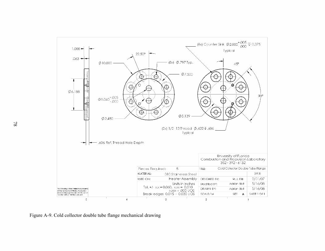
78
Figure A-9. Cold collector double tube flange mechanical drawing

79
Figure A-10. Cold collector single tube exit flange mechanical drawing
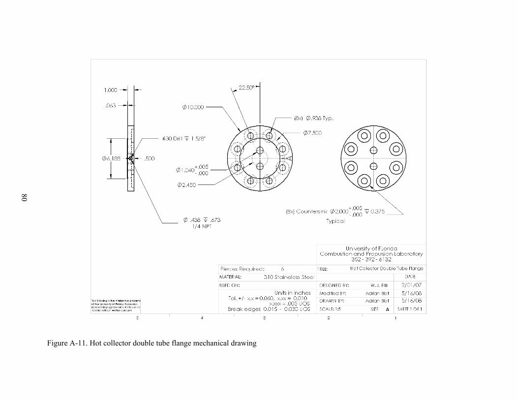
80
Figure A-11. Hot collector double tube flange mechanical drawing
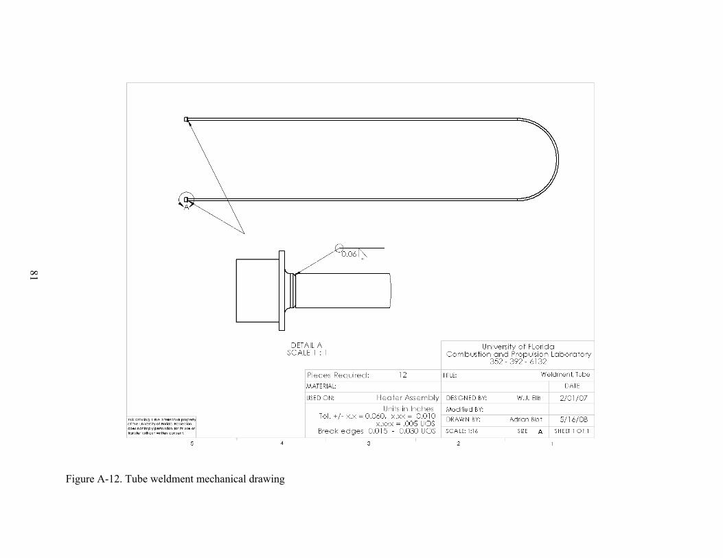
81
Figure A-12. Tube weldment mechanical drawing
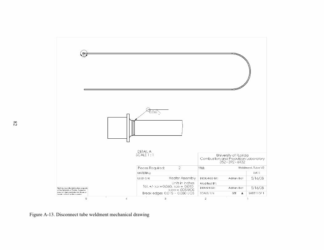
82
Figure A-13. Disconnect tube weldment mechanical drawing
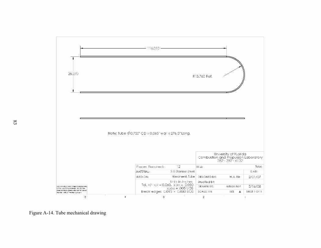
83
Figure A-14. Tube mechanical drawing
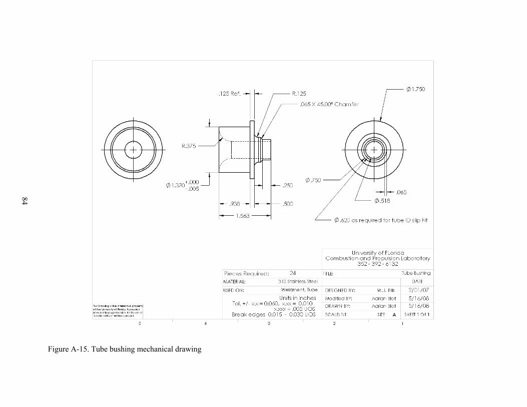
84
Figure A-15. Tube bushing mechanical drawing

85
Figure A-16. Cold collector weldment mechanical drawing
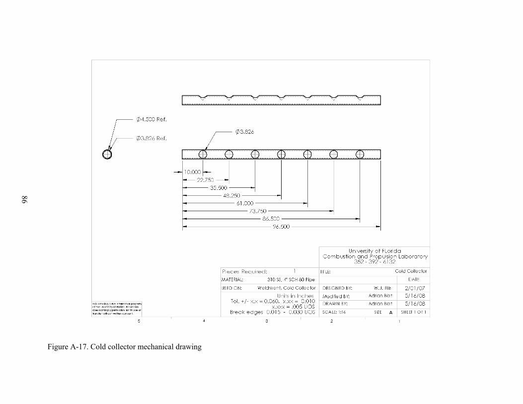
86
Figure A-17. Cold collector mechanical drawing
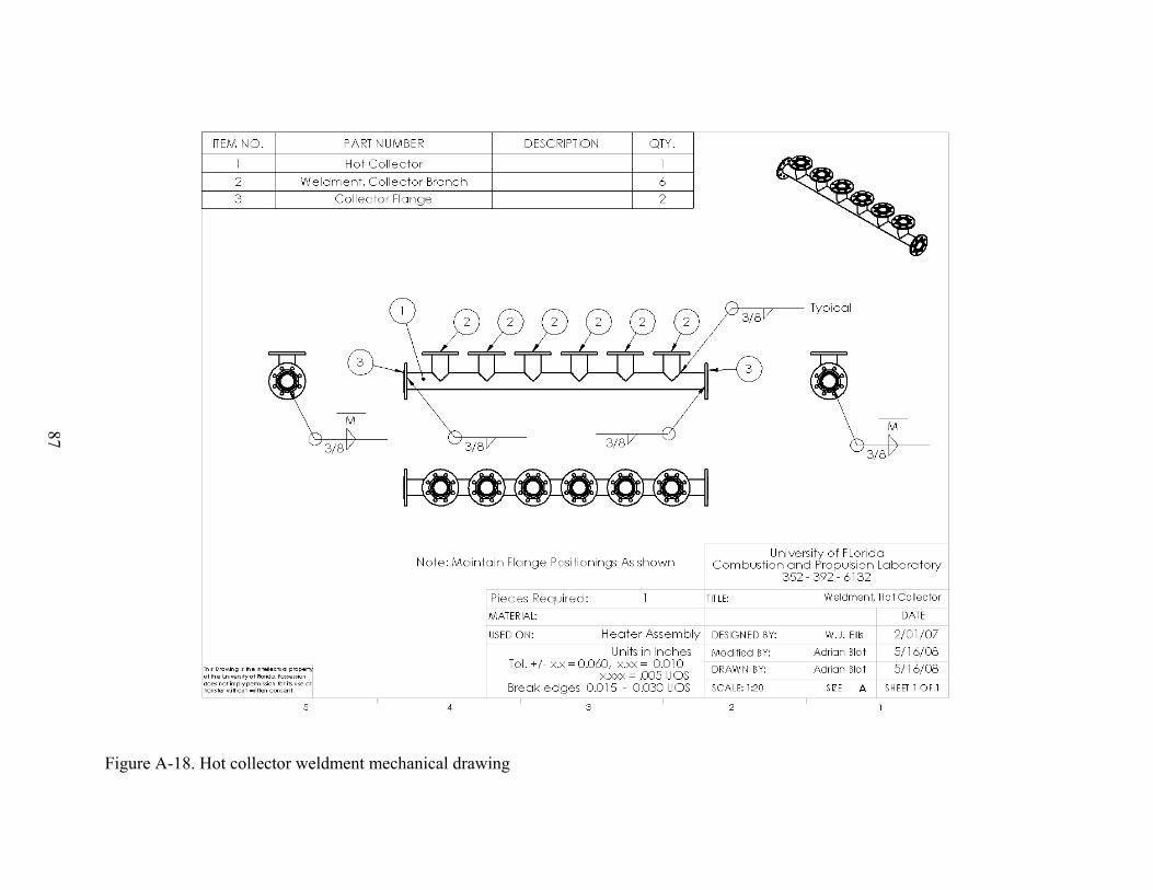
87
Figure A-18. Hot collector weldment mechanical drawing
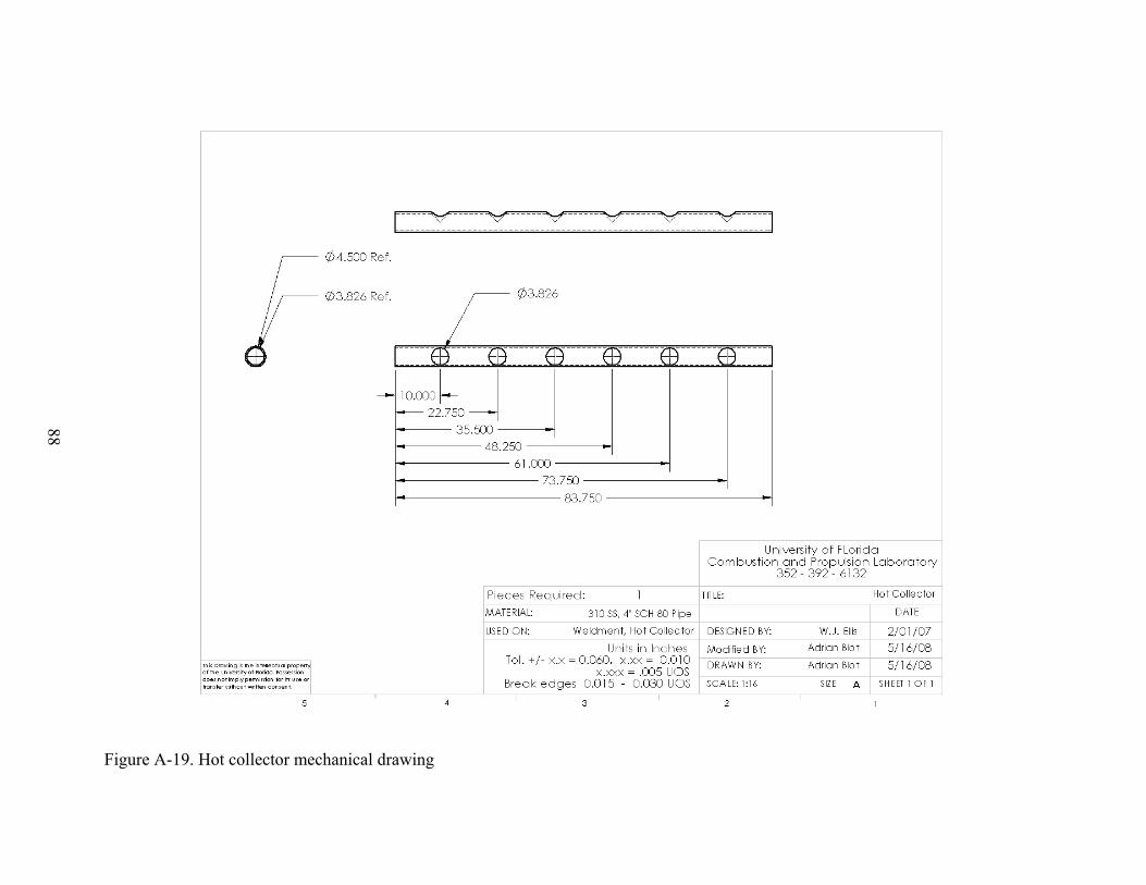
88
Figure A-19. Hot collector mechanical drawing
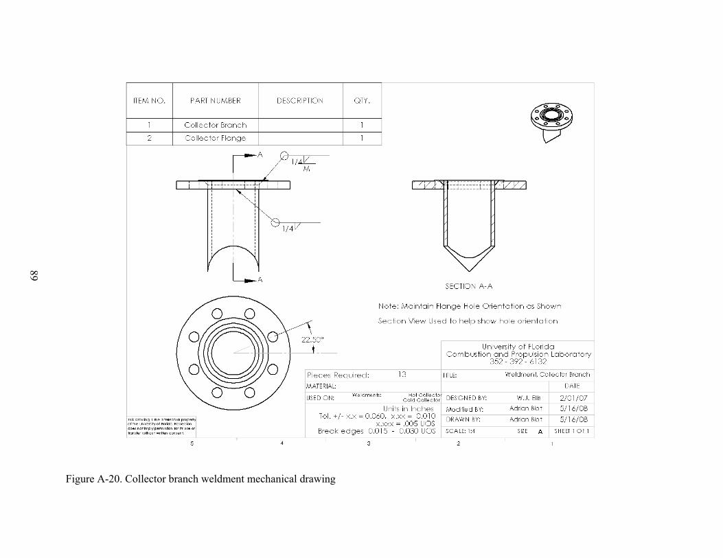
89
Figure A-20. Collector branch weldment mechanical drawing
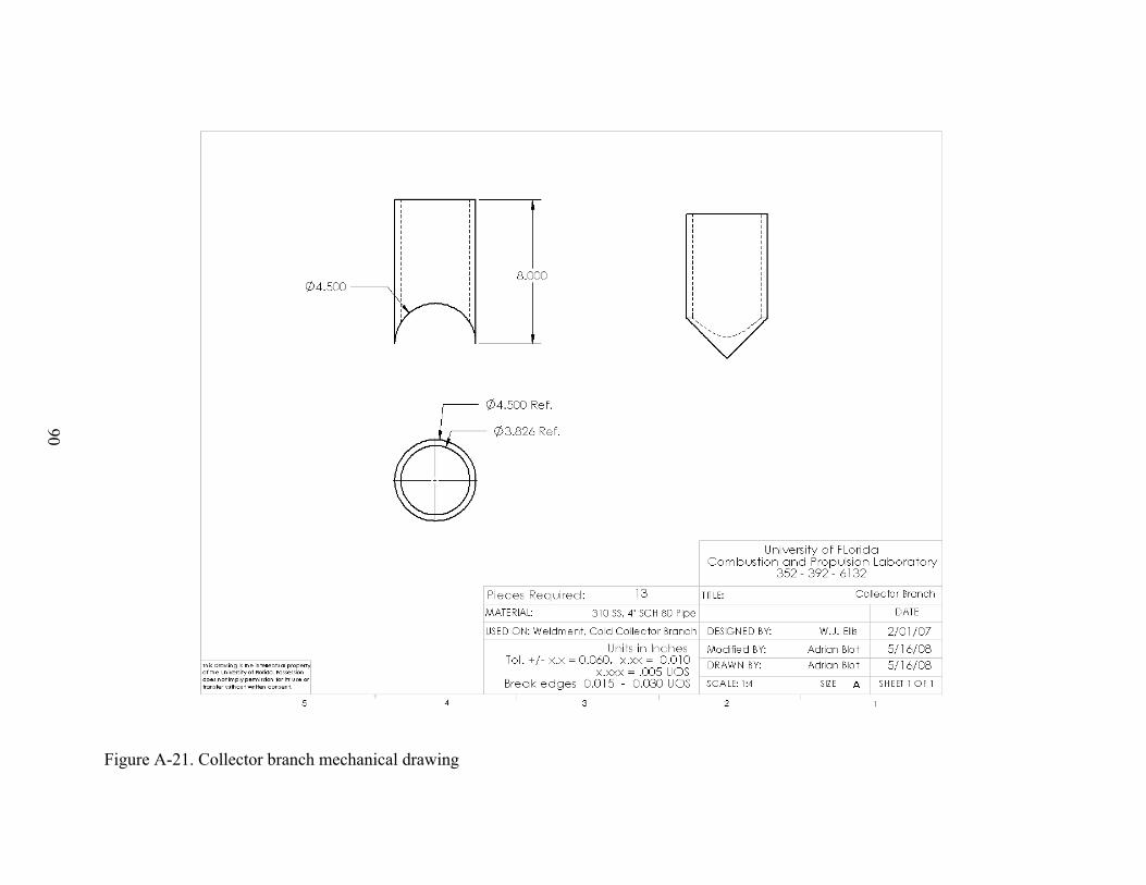
90
Figure A-21. Collector branch mechanical drawing
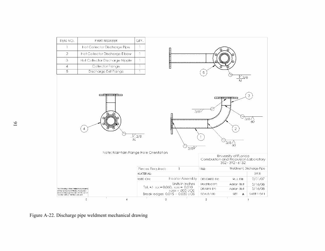
91
Figure A-22. Discharge pipe weldment mechanical drawing
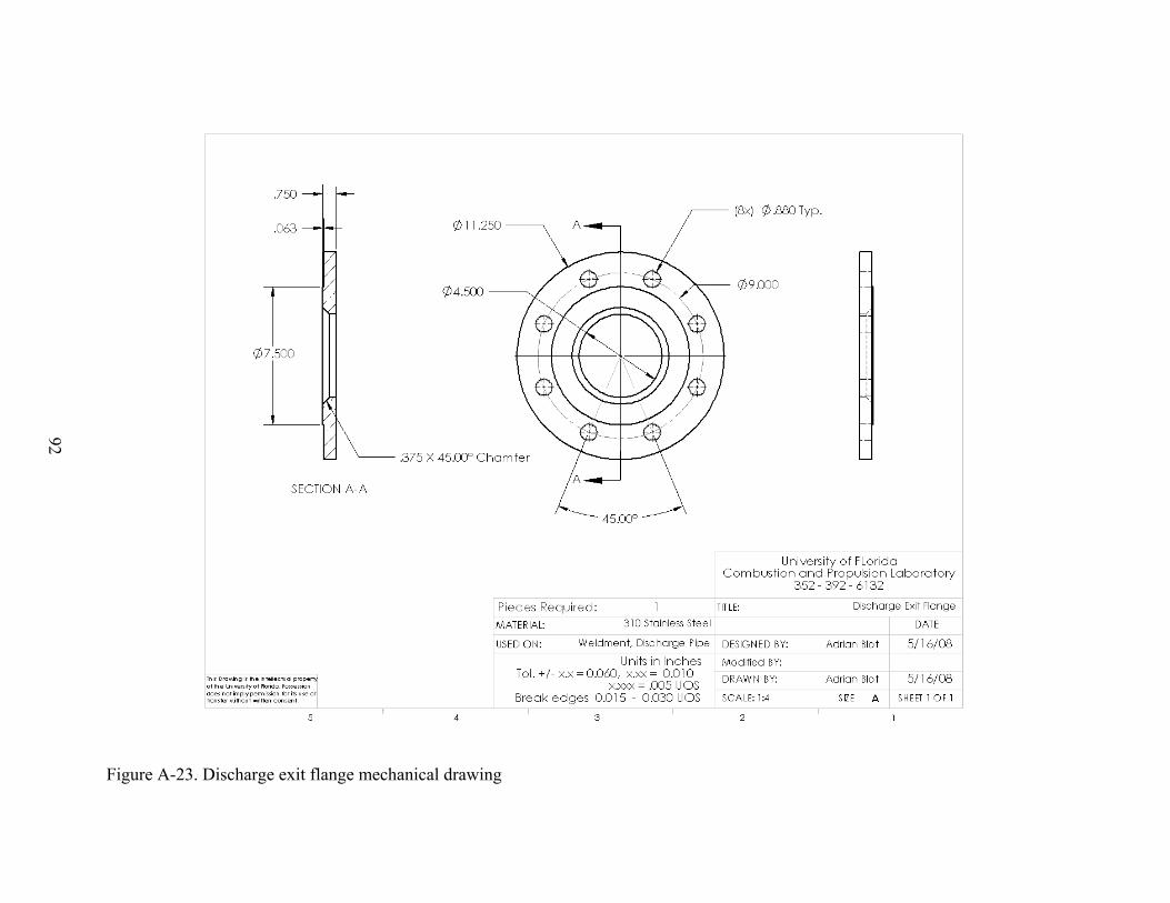
92
Figure A-23. Discharge exit flange mechanical drawing
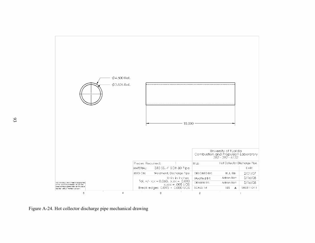
93
Figure A-24. Hot collector discharge pipe mechanical drawing

94
Figure A-25. Hot collector discharge nipple mechanical drawing
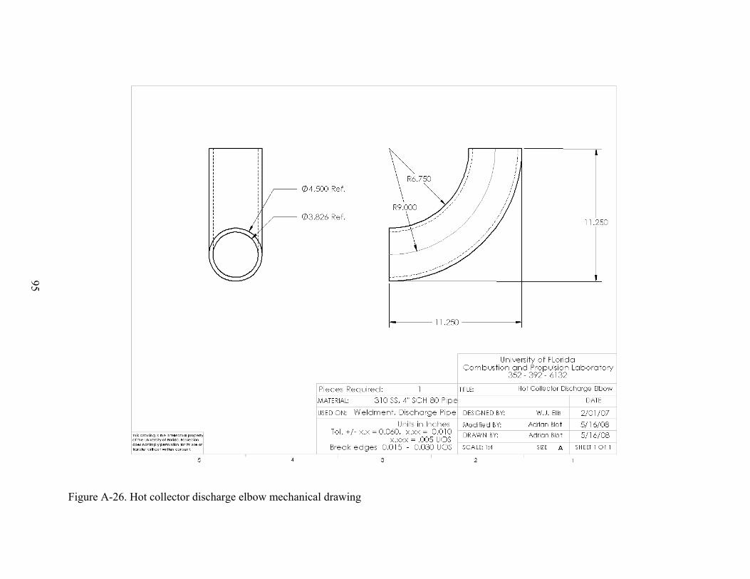
95
Figure A-26. Hot collector discharge elbow mechanical drawing
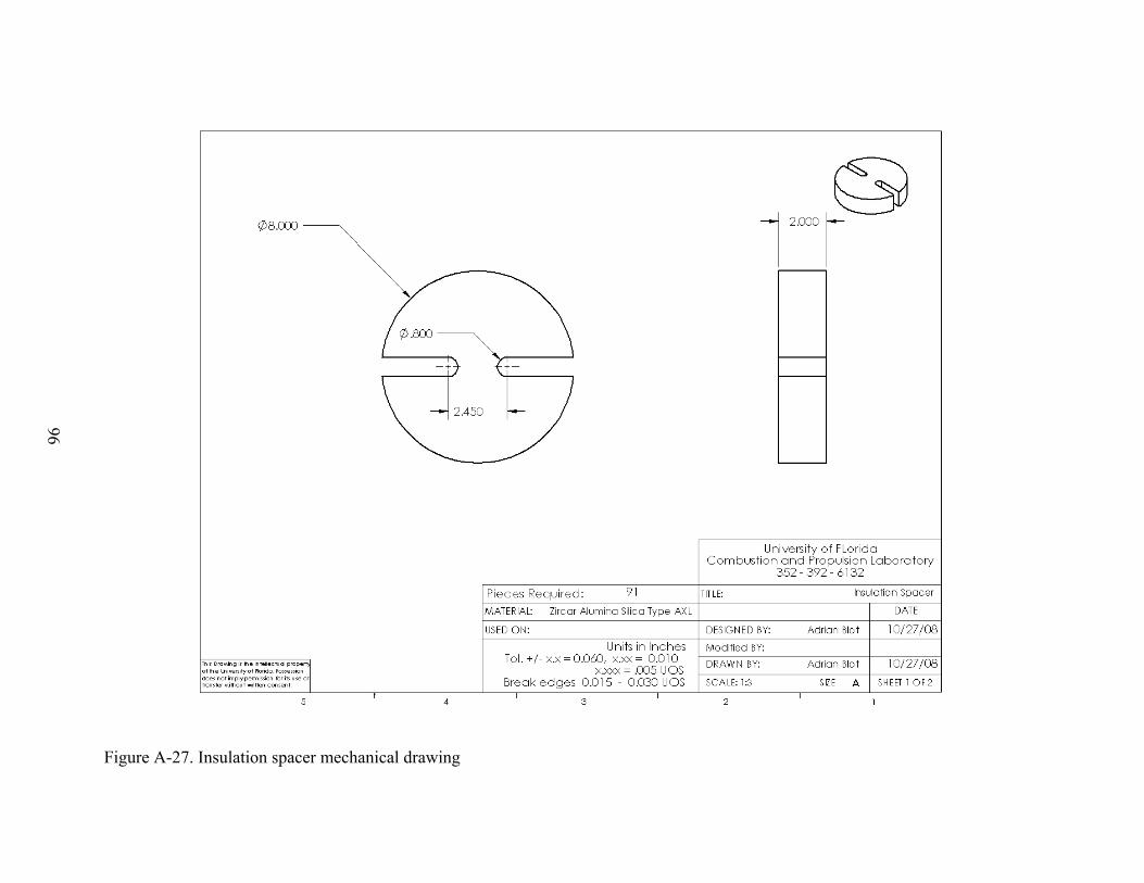
96
Figure A-27. Insulation spacer mechanical drawing

97
Figure A-28. Semi cylinder insulation mechanical drawing

98
APPENDIX B HEATER ENCLOSURE DRAWINGS

99
Figure B-1. Enclosure bill of materials for all parts
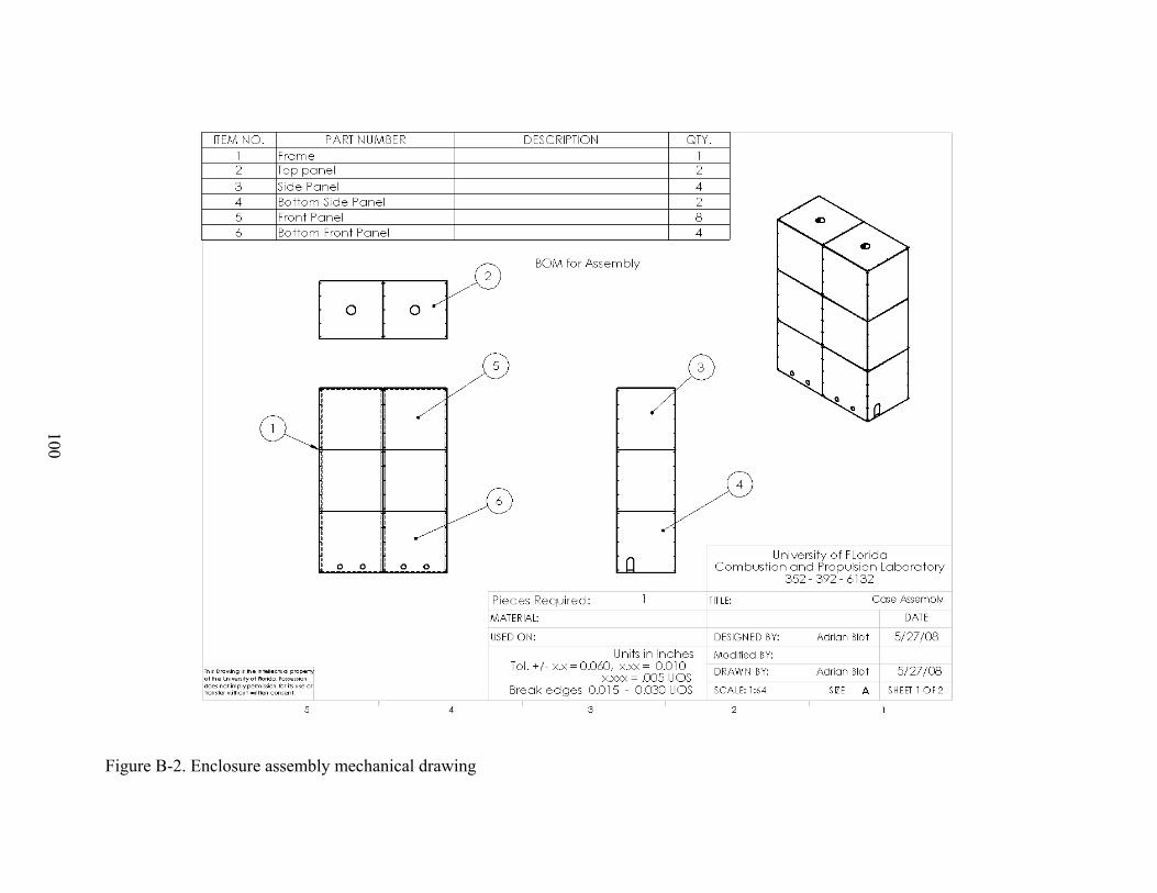
100
Figure B-2. Enclosure assembly mechanical drawing

101
Figure B-3. Frame weldment mechanical drawing
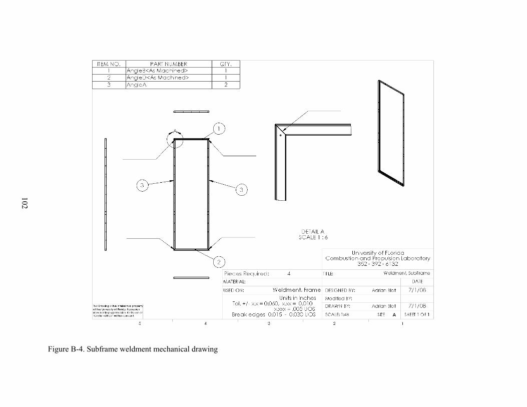
102
Figure B-4. Subframe weldment mechanical drawing
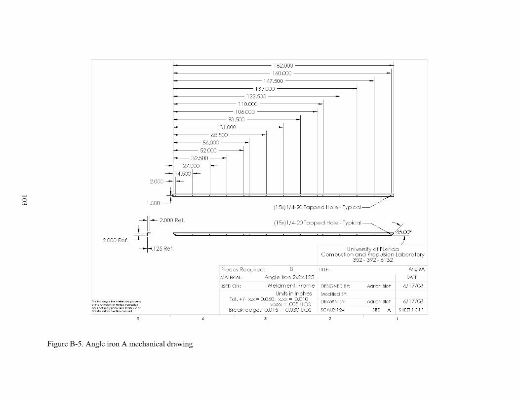
103
Figure B-5. Angle iron A mechanical drawing
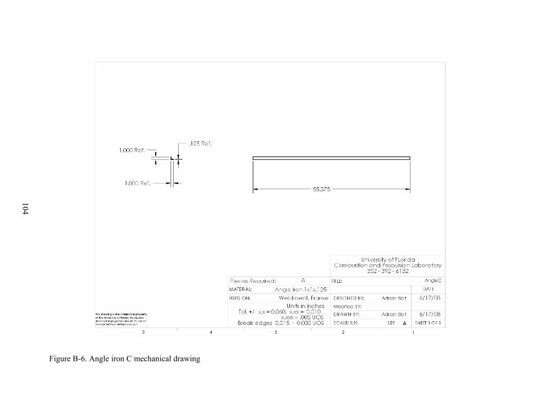
104
Figure B-6. Angle iron C mechanical drawing
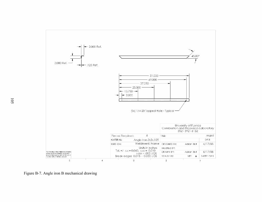
105
Figure B-7. Angle iron B mechanical drawing
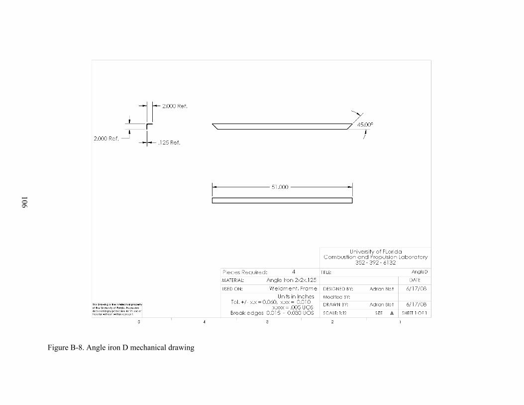
106
Figure B-8. Angle iron D mechanical drawing
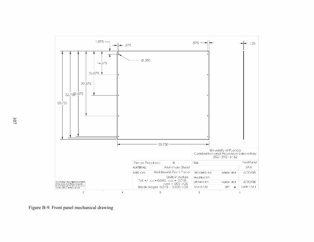
107
Figure B-9. Front panel mechanical drawing
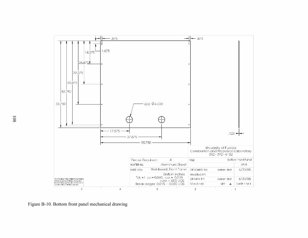
108
Figure B-10. Bottom front panel mechanical drawing
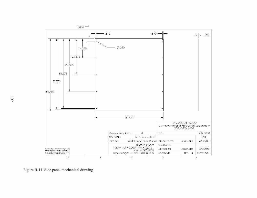
109
Figure B-11. Side panel mechanical drawing

110
Figure B-12. Bottom side panel mechanical drawing
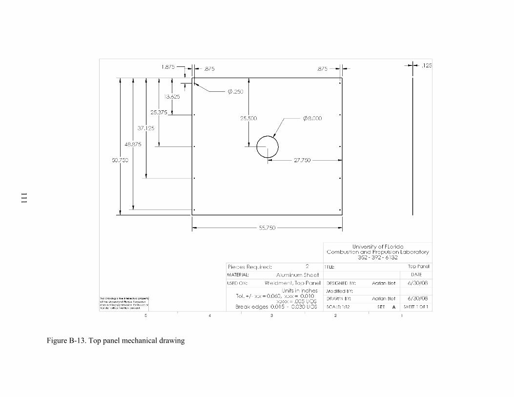
111
Figure B-13. Top panel mechanical drawing

112
APPENDIX C PROTOTYPE HEATER DRAWINGS
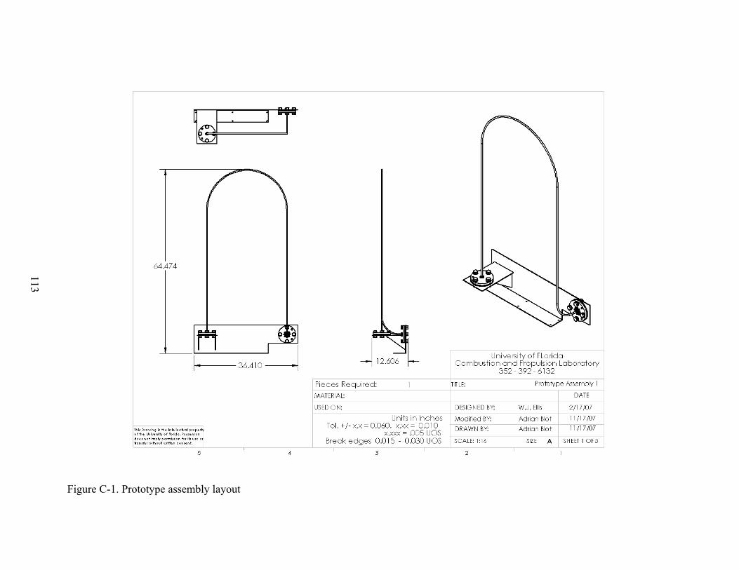
113
Figure C-1. Prototype assembly layout
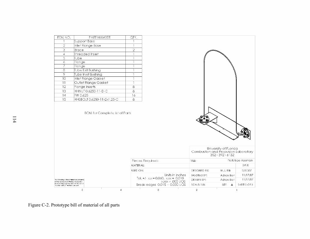
114
Figure C-2. Prototype bill of material of all parts
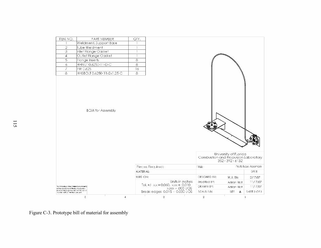
115
Figure C-3. Prototype bill of material for assembly
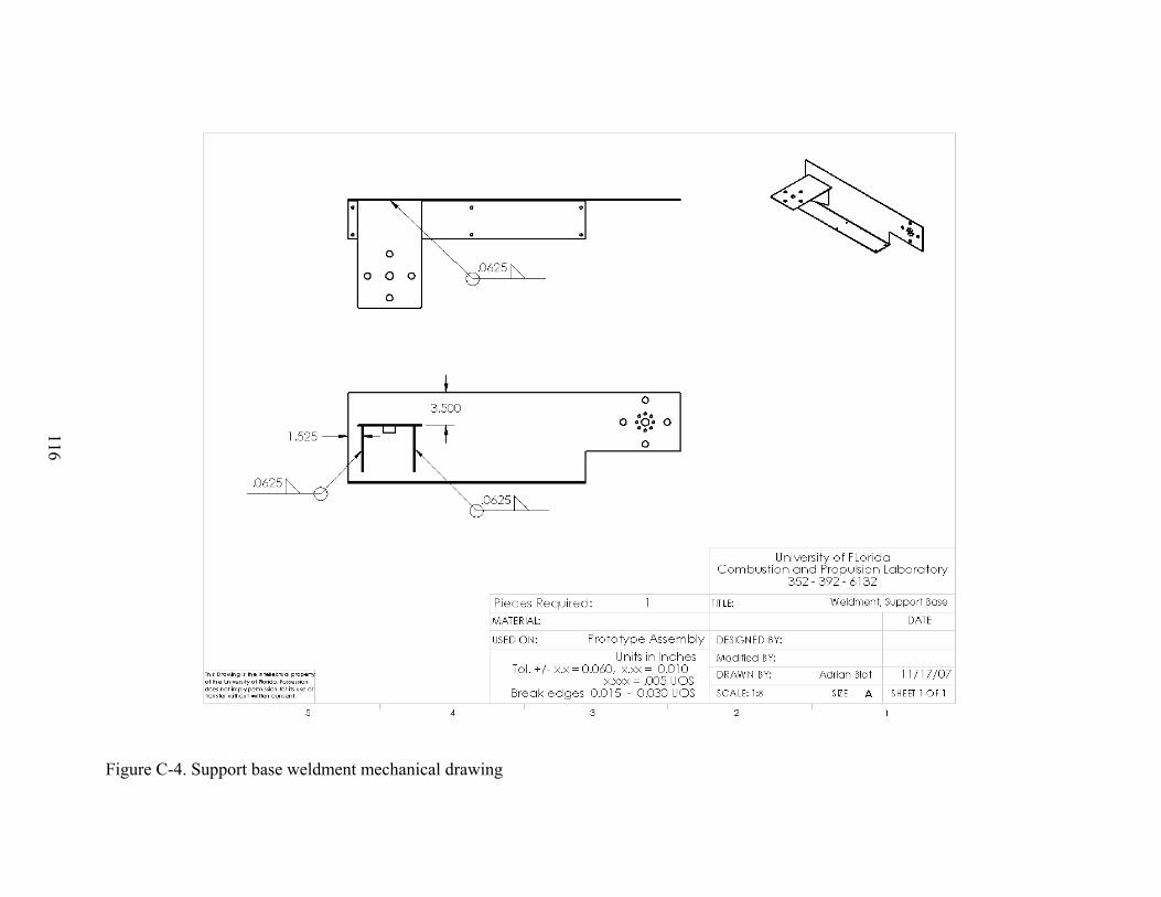
116
Figure C-4. Support base weldment mechanical drawing
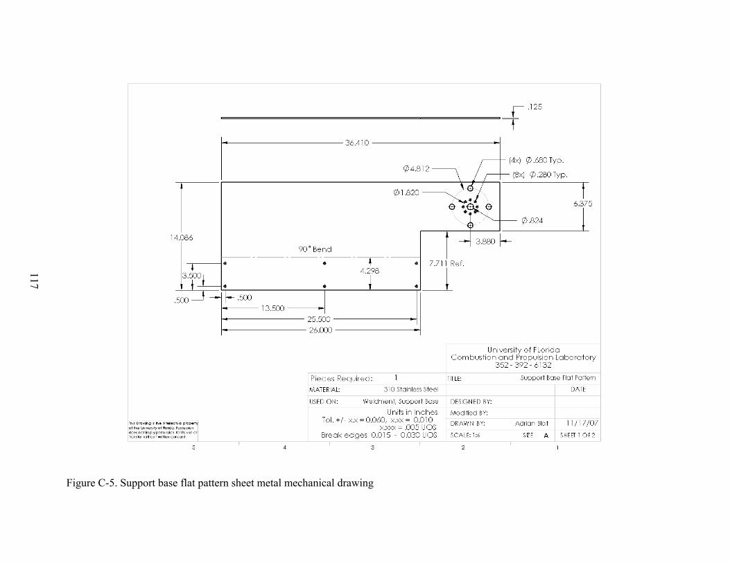
117
Figure C-5. Support base flat pattern sheet metal mechanical drawing
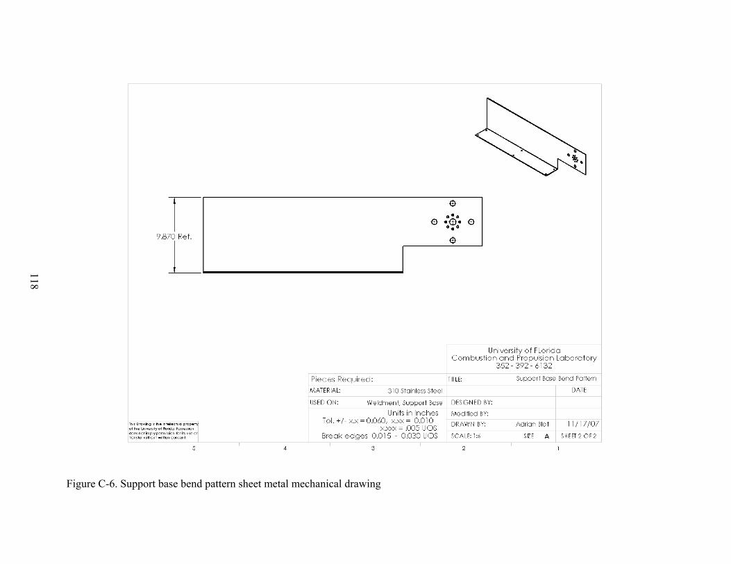
118
Figure C-6. Support base bend pattern sheet metal mechanical drawing
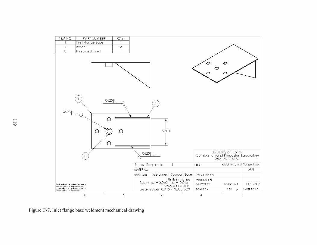
119
Figure C-7. Inlet flange base weldment mechanical drawing
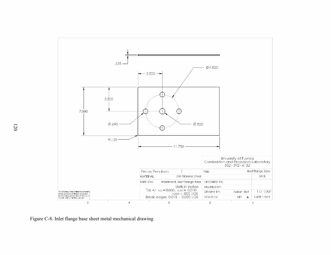
120
Figure C-8. Inlet flange base sheet metal mechanical drawing
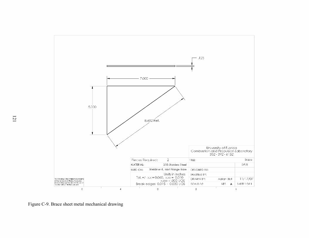
121
Figure C-9. Brace sheet metal mechanical drawing
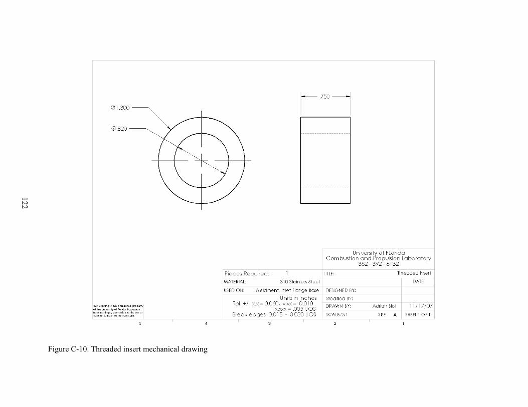
122
Figure C-10. Threaded insert mechanical drawing
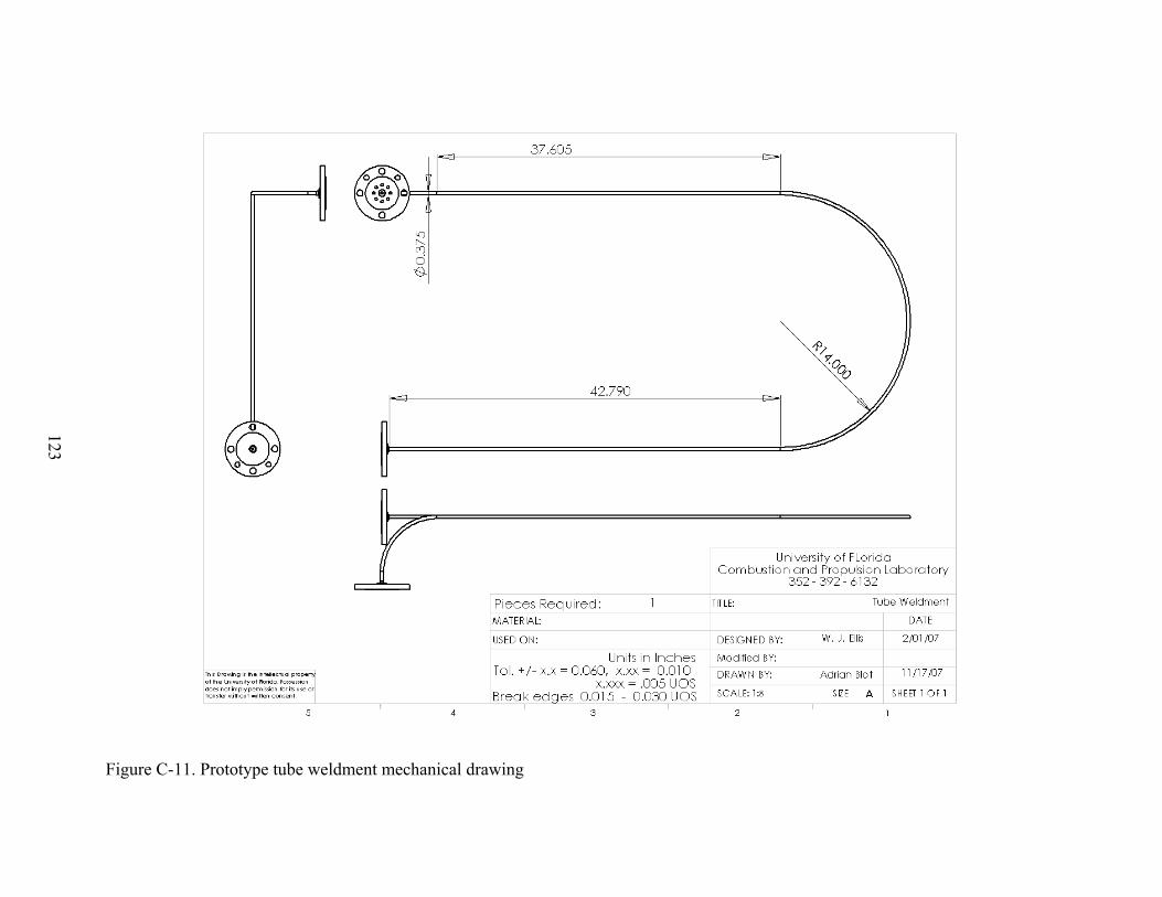
123
Figure C-11. Prototype tube weldment mechanical drawing
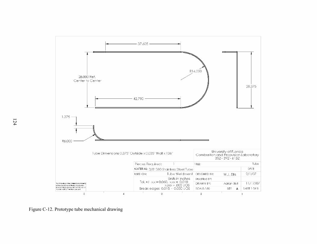
124
Figure C-12. Prototype tube mechanical drawing
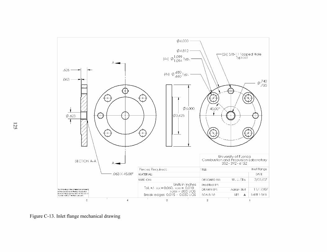
125
Figure C-13. Inlet flange mechanical drawing
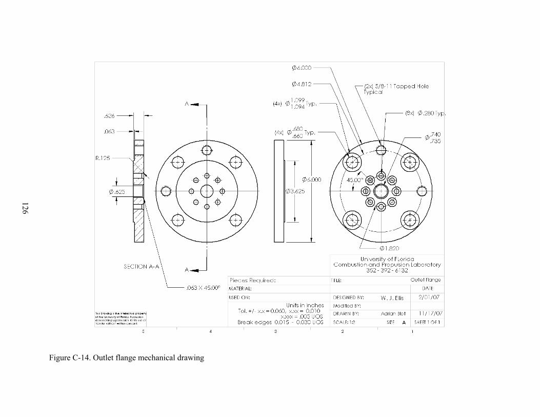
126
Figure C-14. Outlet flange mechanical drawing
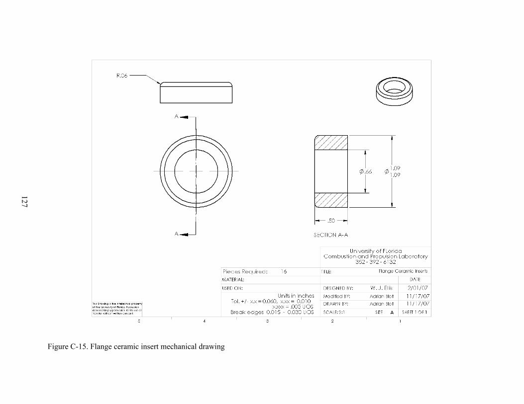
127
Figure C-15. Flange ceramic insert mechanical drawing
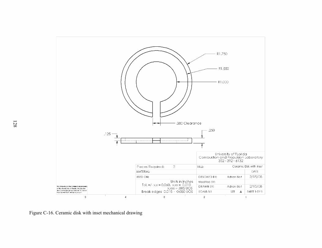
128
Figure C-16. Ceramic disk with inset mechanical drawing
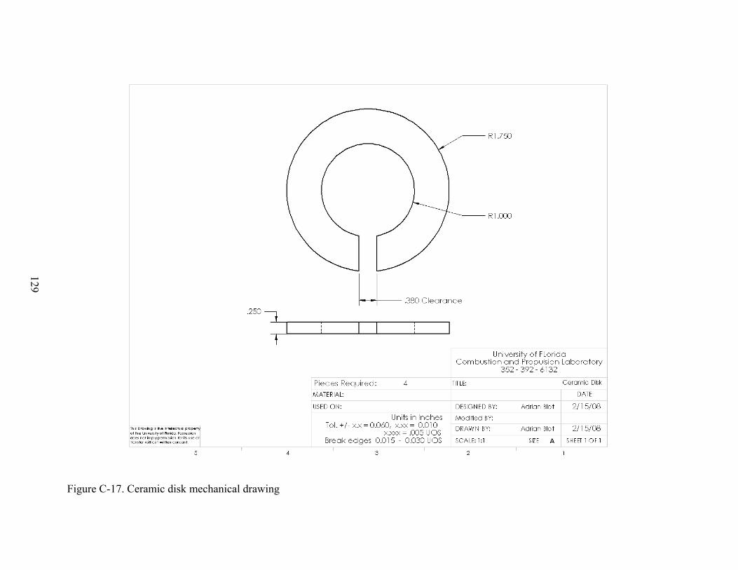
129
Figure C-17. Ceramic disk mechanical drawing
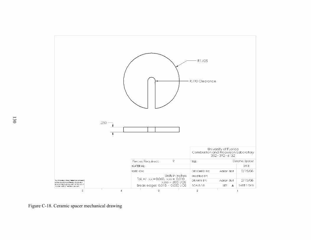
130
Figure C-18. Ceramic spacer mechanical drawing

131
APPENDIX D SECOND STAGE HEATER DRAWINGS
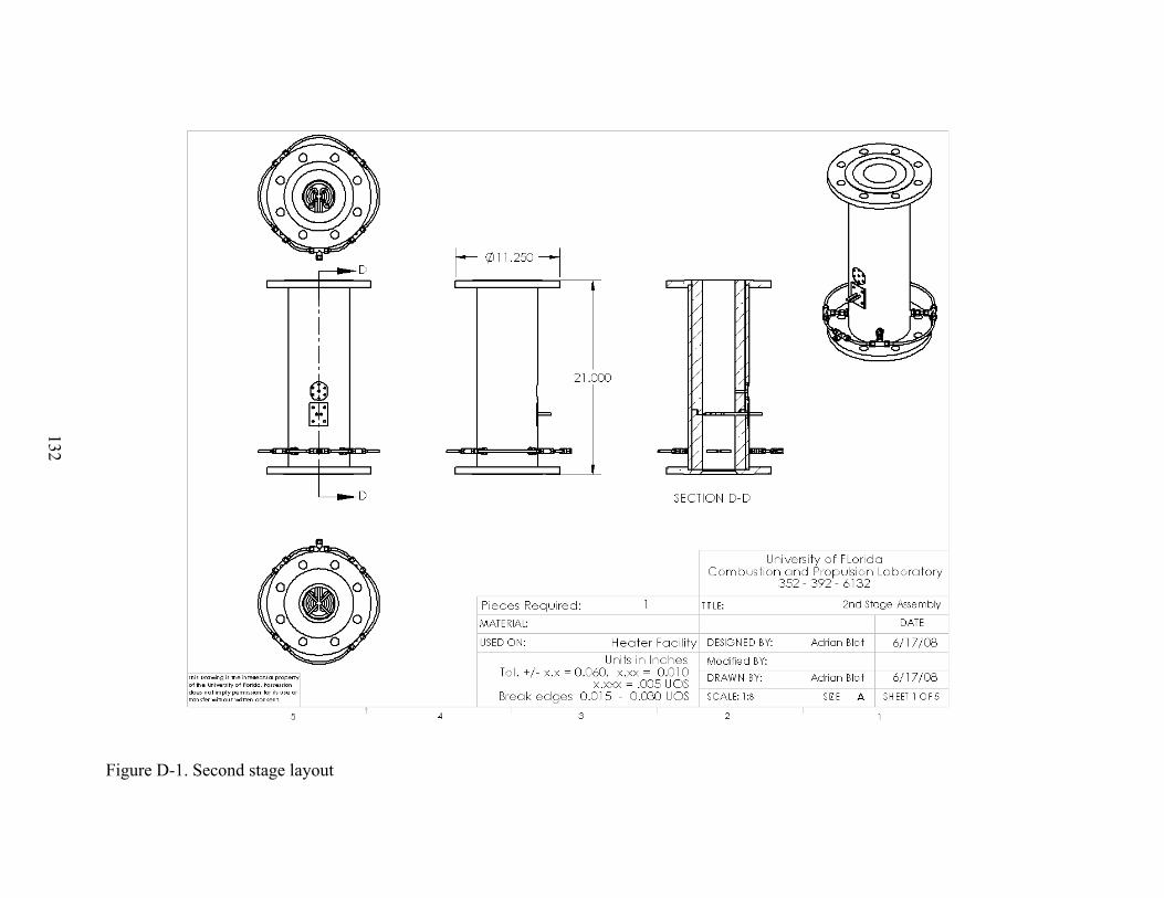
132
Figure D-1. Second stage layout
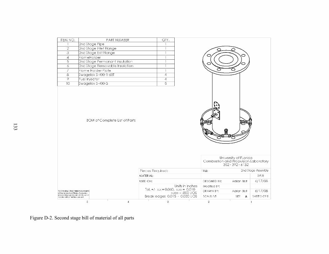
133
Figure D-2. Second stage bill of material of all parts
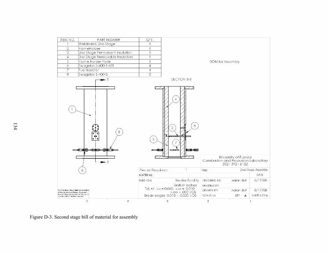
134
Figure D-3. Second stage bill of material for assembly
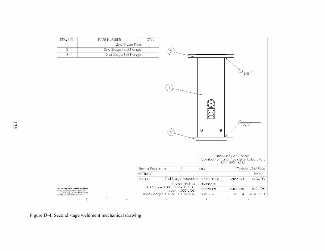
135
Figure D-4. Second stage weldment mechanical drawing
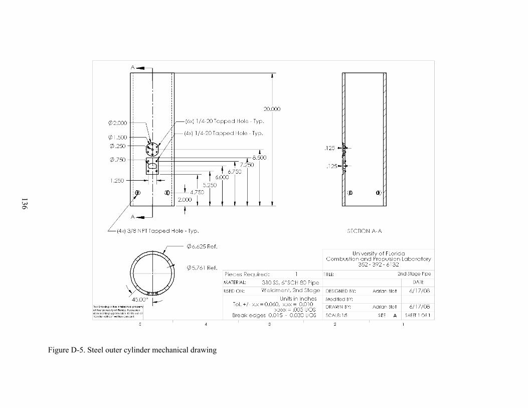
136
Figure D-5. Steel outer cylinder mechanical drawing

137
Figure D-6. Second Stage inlet flange mechanical drawing
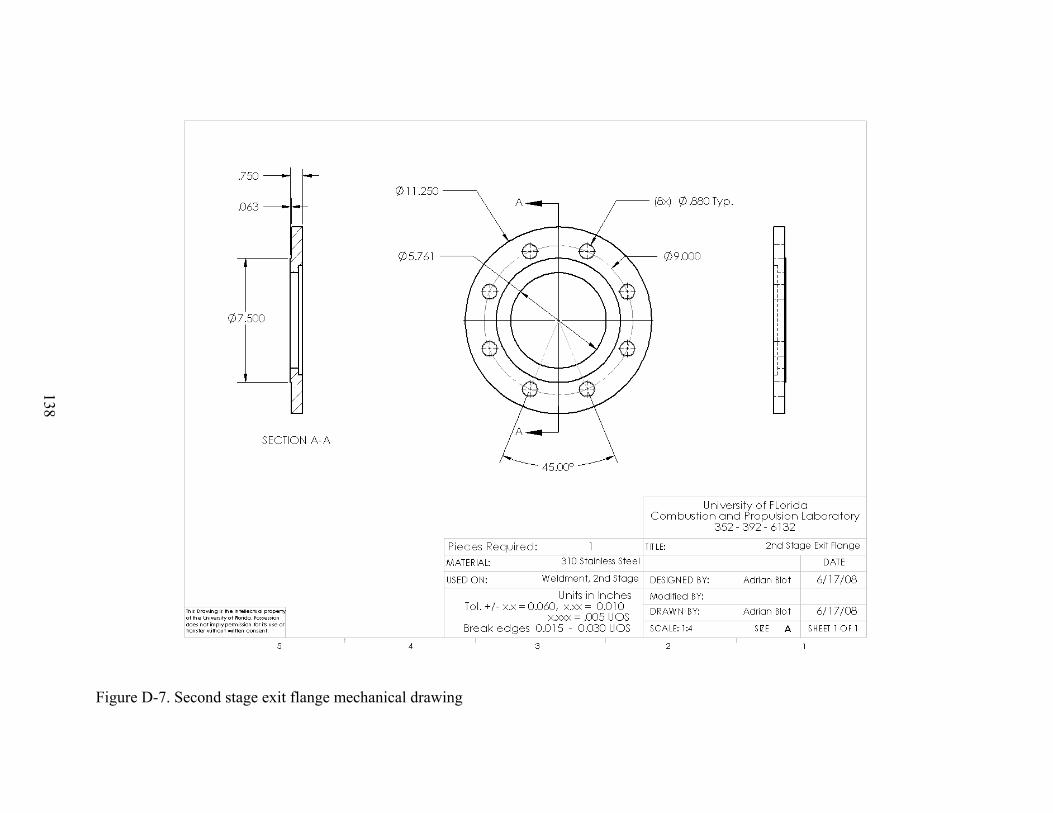
138
Figure D-7. Second stage exit flange mechanical drawing

139
Figure D-8. Permanent insulation mechanical drawing
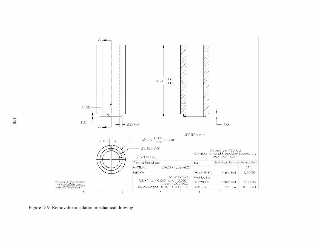
140
Figure D-9. Removable insulation mechanical drawing
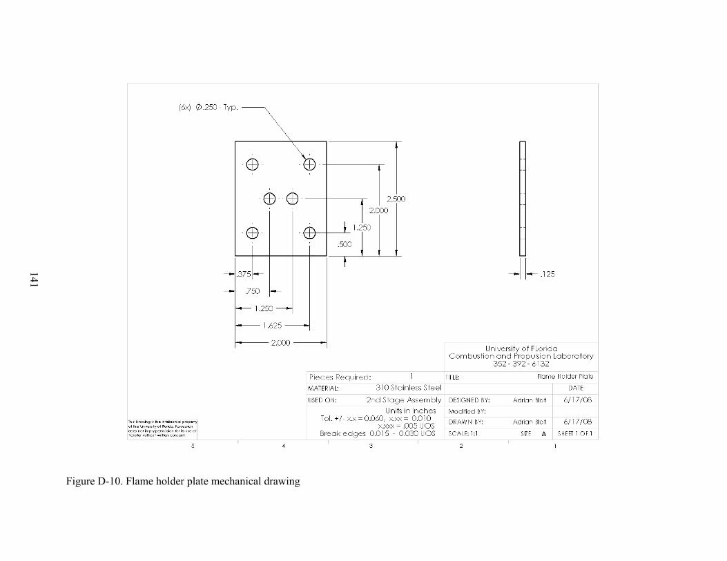
141
Figure D-10. Flame holder plate mechanical drawing
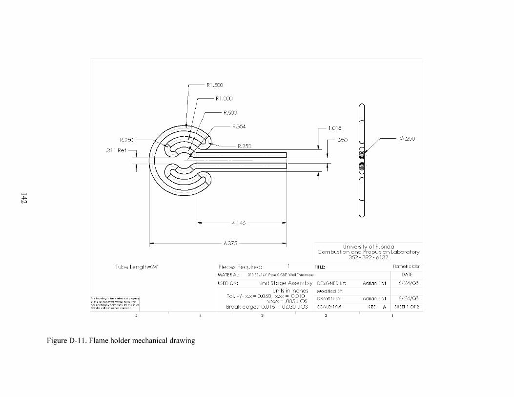
142
Figure D-11. Flame holder mechanical drawing
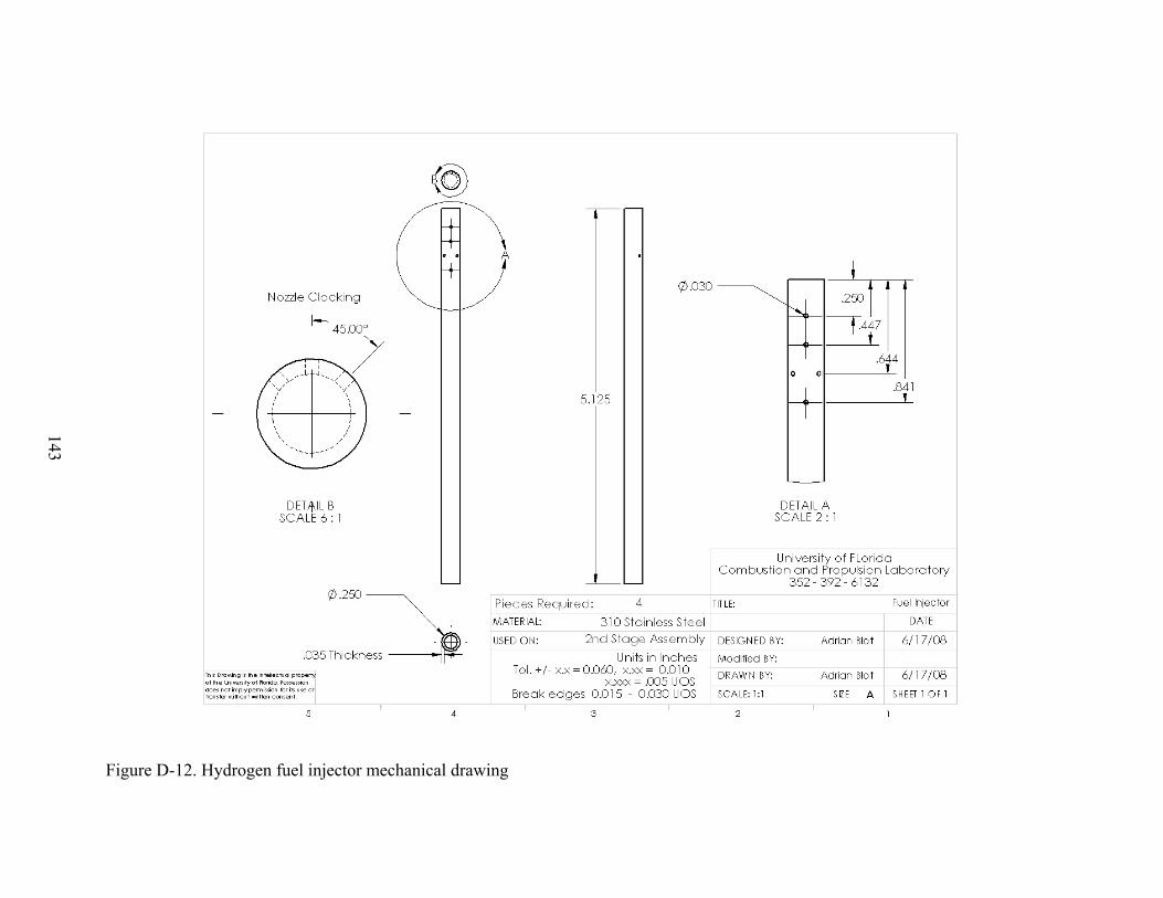
143
Figure D-12. Hydrogen fuel injector mechanical drawing

144
APPENDIX E BELLMOUTH DRAWINGS
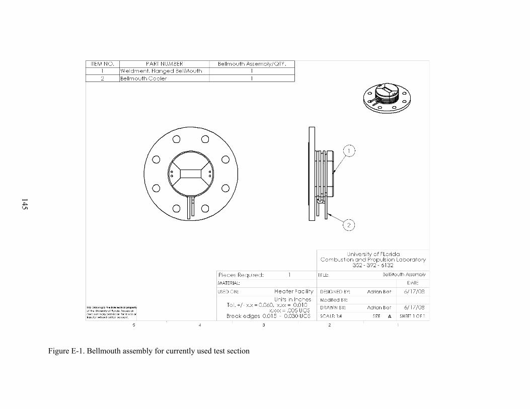
145
Figure E-1. Bellmouth assembly for currently used test section
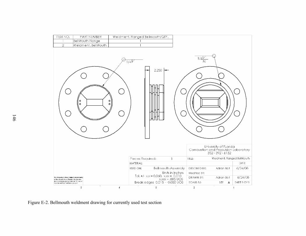
146
Figure E-2. Bellmouth weldment drawing for currently used test section
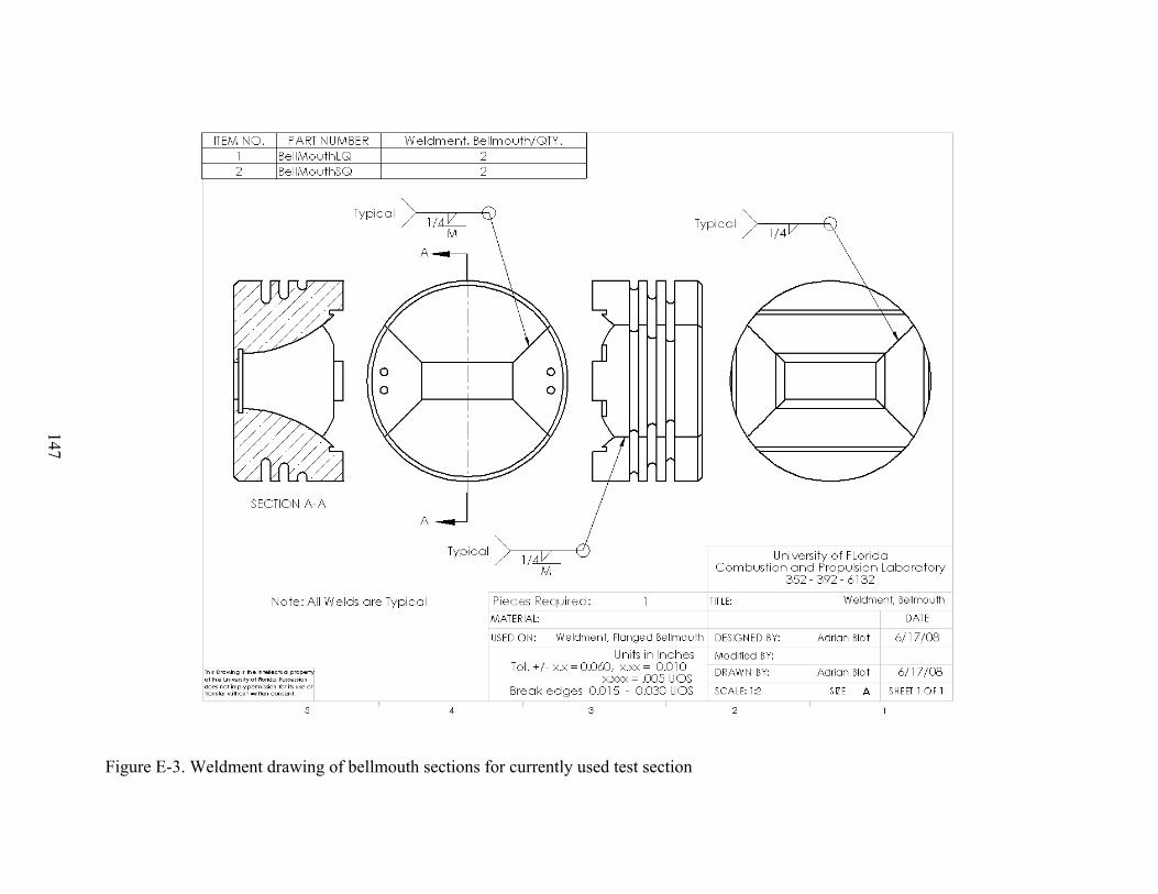
147
Figure E-3. Weldment drawing of bellmouth sections for currently used test section
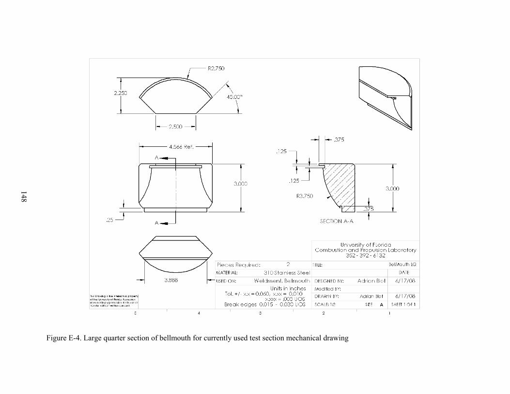
148
Figure E-4. Large quarter section of bellmouth for currently used test section mechanical drawing
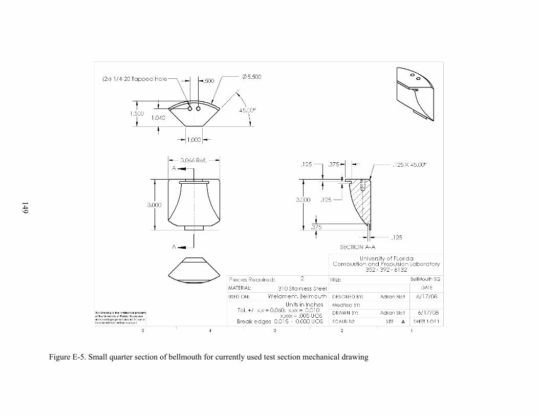
149
Figure E-5. Small quarter section of bellmouth for currently used test section mechanical drawing
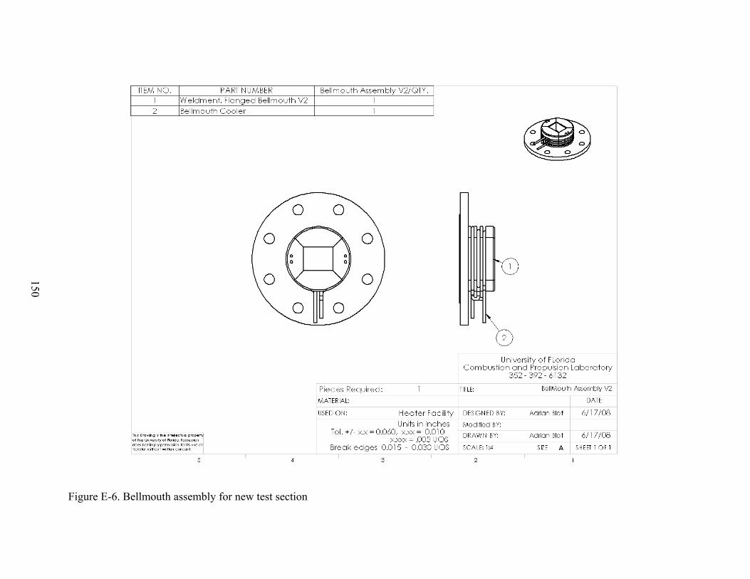
150
Figure E-6. Bellmouth assembly for new test section
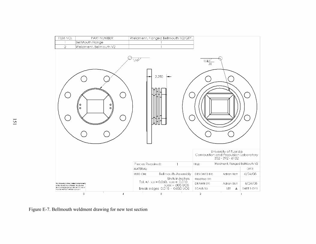
151
Figure E-7. Bellmouth weldment drawing for new test section
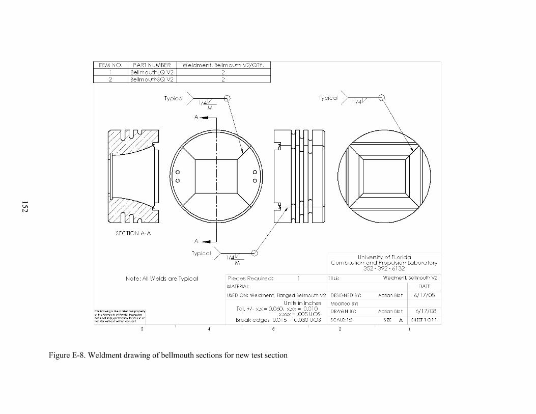
152
Figure E-8. Weldment drawing of bellmouth sections for new test section
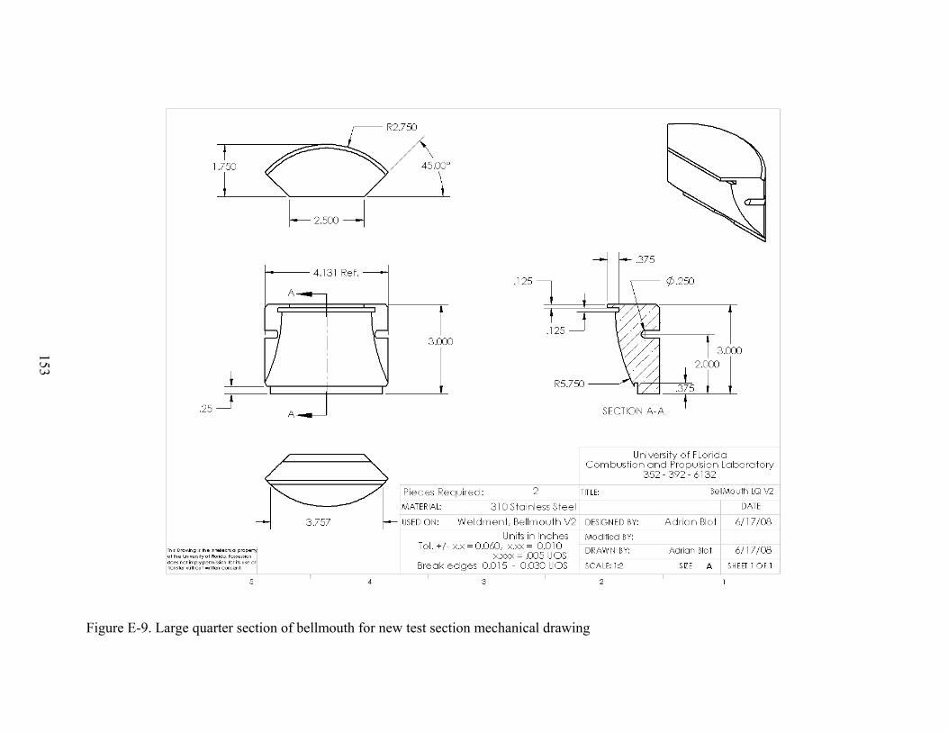
153
Figure E-9. Large quarter section of bellmouth for new test section mechanical drawing
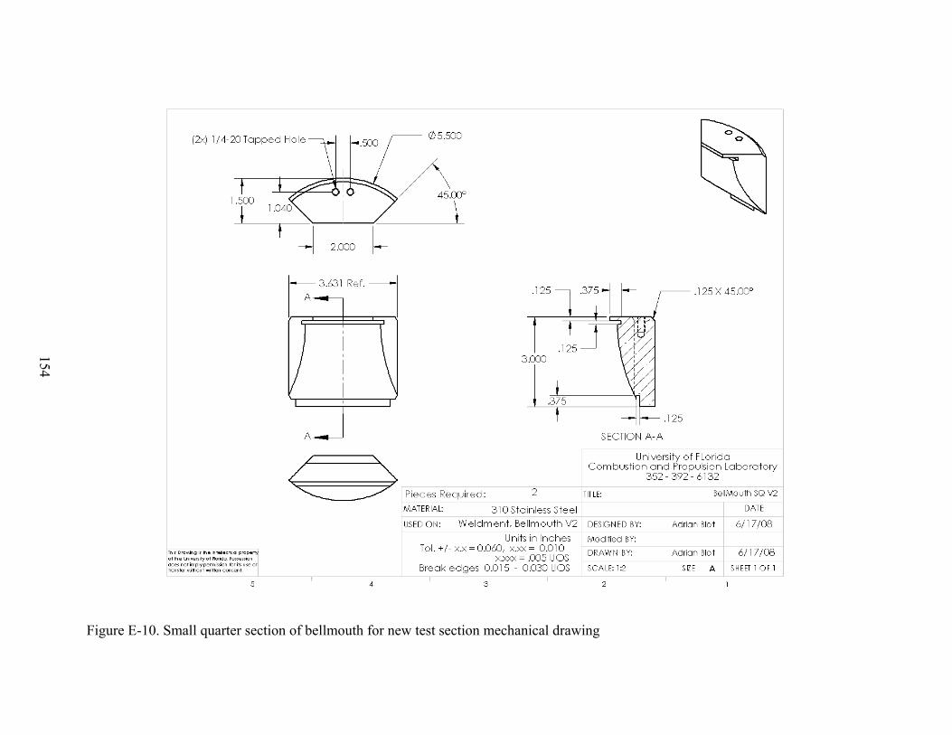
154
Figure E-10. Small quarter section of bellmouth for new test section mechanical drawing
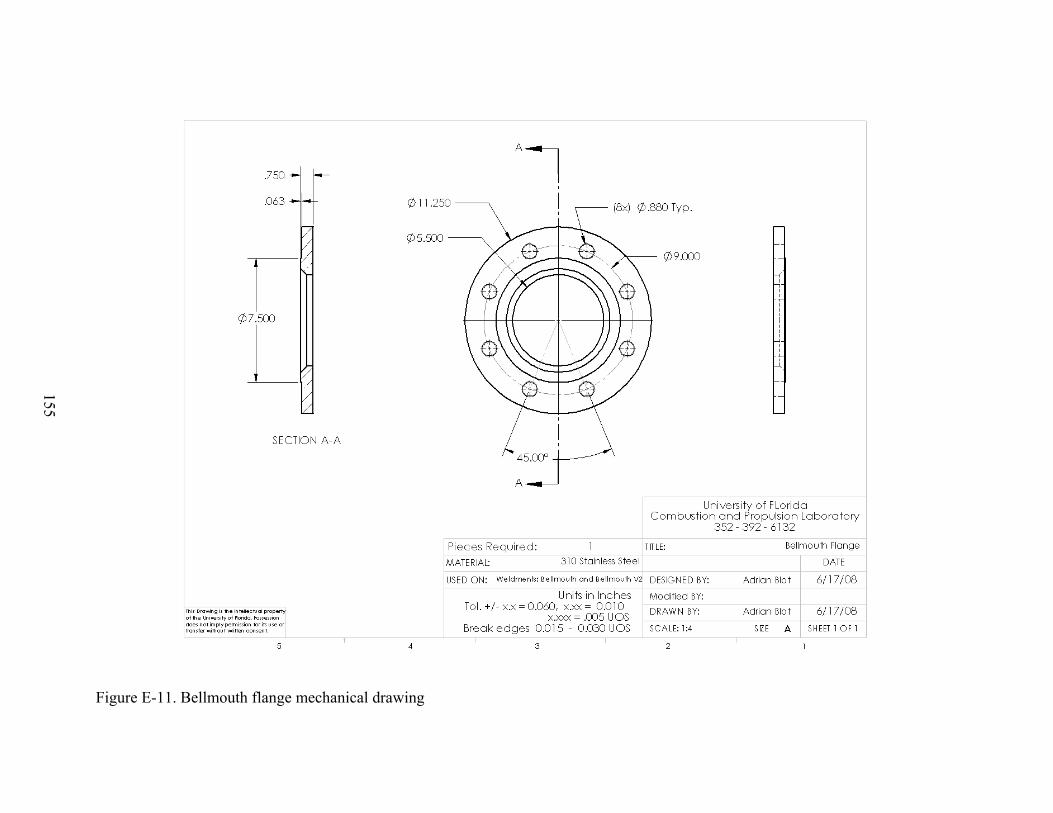
155
Figure E-11. Bellmouth flange mechanical drawing

156
Figure E-12. General mechanical drawing of bellmouth cooling coil
157
LIST OF REFERENCES
1. Bushnell, D. M., “Hypersonic Ground Test Requirements”, AIAA Journal, vol. 198, 2002, pp
1-15.
2. Lu, F. K. and Marren, D. E., “Principles of Hypersonic Test Facility Development”, AIAA
Journal, vol. 198, 2002, pp 17-27.
3. Andreadis, D., “Scramjet Engines Enabling the Seamless Integration of Air & Space Operations”, 2006, Retrieved December 11, 2007 from PWR Engineering: Data and Resources Web Site: http://www.pwrengineering.com/data.htm
4. Russo, G., De Filippis, F., Borrelli, S., Marini, M., and Carista, S., “The SCIROCCO 70-MW Plasma Wind Tunnel: A New Hypersonic Capability”, AIAA Journal, vol. 198, 2002, pp
315-351.
5. Rigney, S.J. and Garrard, G.D., “Aerodynamic and Propulsion Test Unit”, AIAA Journal,
vol. 198, 2002, pp 353-373.
6. Woike, M. R. and Willis, B. P., “NASA Glenn Research Center’s Hypersonic Tunnel
Facility”, AIAA Journal, vol. 198, 2002, pp 427-439.
7. Chue, R. S. M., Tsai, C.-Y, Bakos, R. J. and Erdos, J. I., “NASA’s HYPULSE Facility at
GASL – A Dual Mode Dual Driver Reflected-Shock/Expansion Tunnel”, AIAA Journal, vol.
198, 2002, pp 29-71.
8. Smith, D.M., Felderman, E. J., and Shope, F.L., “Arc-Heated Facilities”, AIAA Journal, vol.
198, 2002.
9. Hodge, J.S. and Harvin, S.F., “NASA Langley Research Center 8-ft HTT”, AIAA Journal, vol. 198, 2002, pp 405-425.
10. Olivier, H., Zonglin, J., Yu, H. R., and Lu, F. K., “Detonation-Driven Shock Tubes and Tunnels”, AIAA Journal, vol. 198, 2002, pp 135-203.
11. Itoh, K., “Characteristics of the HIEST and its Applicability for Hypersonic
Aerothermodynamic and Scramjet Research”, AIAA Journal, vol. 198, 2002, pp 239-253.
12. Kislykh, V. V., “Piston Gasdynamic Units with Multicascade Compression”, AIAA Journal,
vol. 198, 2002, pp 255-277.
13. Hennemann, K. and Beck, W. H., “Aerothermodynamics Research”, AIAA Journal, vol. 198, 2002, pp 205-237.
14. Cengel, Y., Heat and Mass Transfer, 3rd ed., McGraw Hill, New York, 2007.
15. Jacobsen, L. S., “Plasma assisted Ignition in Scramjets”, Journal of Propulsion and Power,
2008.

158
16. Ibele, W.E., “Prandtl number measurements and Thermal Conductivity, Viscosity Prediction for air, Helium, and Air-Helium Mixtures”, University of Minnesota, 1963.
17. Turns, Stephen R., An Introduction to Combustion Concepts and Applications, McGraw Hill, New York, 2006.

159
BIOGRAPHICAL SKETCH
Adrian Blot was born in Ris Orangis, France in 1984, but grew up in Florida and Virginia.
In 2003 Adrian began attendance at the New York Institute of Technology in Old Westbury, NY.
He enjoyed the city life of the Big Apple and after 4 years obtained a Bachelor of Science in
mechanical engineering with concentration in aerospace engineering and graduated summa cum
laude. While there he was also involved in an SAE club geared to the design and production of a
mini Baja vehicle for competition. Adrian began work on a Master of Science degree in
aerospace engineering in 2007 at the University of Florida where he joined the Combustion Lab
Group. After graduation Adrian plans to find an engineering position in the western United
States and looks forward to the future challenges that await him.