design of a prototypical dual-axis tracker solar...
TRANSCRIPT

Scientia Iranica D (2018) 25(6), 3542{3558
Sharif University of TechnologyScientia Iranica
Transactions D: Computer Science & Engineering and Electrical Engineeringhttp://scientiairanica.sharif.edu
Design of a prototypical dual-axis tracker solar panelcontrolled by geared dc servomotors
A. Mansouri�, F. Krim, and Z. Khouni
Laboratory of Power Electronics and Industrial Control (LEPCI), Department of Electronics, Faculty of Technology, UniversityFerhat Abbas of SETIF1, El Maabouda, Route de B�ejaia, S�etif 19000, Algeria.
Received 2 December 2015; received in revised form 27 November 2016; accepted 8 January 2018
KEYWORDSArduino Uno;Dual axis;Light-dependentresistor;Low-cost solar tracker;PWM control.
Abstract. The main challenges of solar tracking systems are sunlight sensing formaximum illumination, providing an initial position and delays of PV panel, and designingan adequate control unit for low-consumption servomotors. The objective of this paper isto design and implement an automatic control for directing maximum solar illumination toa photovoltaic (PV) panel. The proposed dual-axis solar tracker panel prototype is usedto optimize the conversion of solar energy into electricity by orienting the panel towardthe real position of the sun, at a cost of mechanical complexity and maintenance need,for the best e�ciency. In hardware development, two geared dc servomotors are adjustedby Pulse Width Modulation (PWM) which is controlled by a drive unit moving the panelusing four Light-Dependent Resistors (LDR) to provide analog signals; these signals areprocessed by a simple and low-energy ATMEGA328P microcontroller with Arduino. Forthe software part, after data processing, a C++ programming controls two dc servomotorsto position light sensors in the most favorable direction, where solar panel and sensors canbe perpendicular to the sunlight.© 2018 Sharif University of Technology. All rights reserved.
1. Introduction
Regarding the continuous depletion and pollution ofresources by using fossil fuels (oil, natural gas, coal,etc.), thermonuclear (Uranium, plutonium, etc.), andthe increasing demand for energy during the lastforty years, researchers all over the world struggle todevelop new technologies to produce clean, RenewableElectrical energy (REn) sources, such as solar and windenergy, to make them inexhaustible and accessible.Solar rays produced every day to our planet are milliontimes greater than the consumption rate of the globalelectrical energy need. Solar energy is abundant,non-polluting, silent, reliable, free, and inexhaustible,
*. Corresponding author. Tel.: +213 36 61 60 63E-mail address: [email protected] (A. Mansouri)
doi: 10.24200/sci.2018.20045
needing very low maintenance. For this reason, solarenergy will be widely used to produce clean electricity.
Solar trackers are devices that orient solar panels,Fresnel re ector, mirrors or lenses towards the sun toreceive maximum radiation in the form of light andheat to be converted to thermal energy or produceelectricity. In 1839, the French physicist Alexandre-Edmond Becquerel was the �rst researcher to discoverthat sunlight could be transformed into electricity. Itis the photovoltaic (PV) e�ect. A century later, the�rst PV cells where constructed. The early solarmodules were used in space in 1958. Other emergingtechnologies using multi-junction cells included con-centrator photovoltaic (CPV) and Concentrated SolarPower (CSP), which must use trackers to be pointedat the sun; otherwise, no energy can be produced. Forthese reasons, researchers are interested in motorizingsolar trackers. The main types of sun trackers aremechanical and electrical parts. In 1962, Finster

A. Mansouri et al./Scientia Iranica, Transactions D: Computer Science & ... 25 (2018) 3542{3558 3543
introduced the �rst purely mechanical tracker [1]. In1963, Saavedra designed an automatic electronic con-trol mechanism [2]. Afterwards, several research workshave been carried out on the design of single- and dual-axis solar tracking systems using electromechanicalactuators to allow for about more produced energy(30% to 60%) as compared to the �xed system, becausesunlight remains perpendicular to the PV panels [3-8]. Then, single- or dual-axis solar trackers [9-18],the optimized solar cell con�guration and geometry,new materials and technologies for optoelectronic ap-plications, etc. [19-22] can be used for improving thee�ciency of PV conversion. Although solar trackerscan gain more energy, some problems appear in theirinstallation such as high energy consumption, cost,the issue of (un)reliability and maintenance. It is notrecommended to use a solar tracker for small panelsbecause of high energy loss in the driving systems.It is shown that a tracking device increases energywhile consuming very low amount of power (2 to3%).
The strategic choice of Algeria, a country locatedin the Northern Africa on the Mediterranean coastwhich ranges in latitude from 18.96 south to 37.09north and in longitude from 8.69 west to 11.95 east,has a signi�cant solar potential for renewable energyin the world, recovered from sunlight reaching 3900 h,particularly in the Sahara desert. An Algerian map ofsolar radiation demonstrates solar energy potentials ofthis speci�c zone which provides useful information foroptimum plant selection of solar energy system [23].This map can be used as a database for future in-vestments in solar energy, showing that the highestintensity is detected to be around the area of Djanet(southern Algerian desert) and the less intense areais identi�ed to be around Ksar Chellala (Tiaret HighPlanes).
In 2007, the �rst hybrid plant in the world wasconstructed in Hassi R'Mel in the southern Algeriandesert. It is an ISCC (Integrated Solar CombinedCycle) composed of a conventional combined cycle anda solar �eld with a nominal thermal power of 150 MW.The goal of this project was to integrate the solar ther-mal technology into a conventional power plant whichintegrates a solar �eld of CCP (parabolic throughcollector) covering a re ective area of 180,000 m2. Thiscombined use reduces the cost and facilitates the de-ployment of renewable energies in newly industrializing
countries. The power plant will be constructed inBoughezoul, on the northern edge of the Sahara desert(Aures), and will serve primarily as a pilot and researchfacility. It will be able to operate using just solar energyor as hybrid power plant fuelled by a combination ofsolar power and gas.
Algeria is engaged in a new age of sustainableenergy use [24]. The program consists of installing upto 22 GW of power-generation capacity from renewablesources between 2011 and 2030, of which 12 GW will beintended to meet the domestic electricity demand and10 GW destined for export. This last option dependson the availability of a demand that is ensured in thelong term by reliable partners as well as attractiveexternal funding. It is expected that about 40% ofelectricity for domestic consumption be produced fromrenewable energy sources by 2030. This documentwas produced by the Ministry of Energy and Mines,which was designed and printed by SATINFO, SonelgazGroup Company.
In this context, this paper involves the design andcontrol of the prototype of a dual-axis solar trackingsystem for solar PV panel to improve energy e�ciency.Tracking system for solar PV panel improves theextraction of maximum solar energy. The system iscomposed of two basic parts: the mechanical assemblyand electrical parts. The electric part is composedof four identical LDRs as the input, the ATMEGAmicrocontroller as the controller, and two servomotorsas the output.
2. Solar tracking panels
Considering the geographic situation in Africa, Algeriaenjoys one of the most important sunny capacities inthe world with 2200 KWh/m2/annum. The insola-tion in most areas of the annual national territoriesreaches 2000 hours and may reach 3900 hours inthe Sahara. Daily received energy within a hori-zontal area of 1 m2 is nearly 5 kWh in the majorzones, 1700 kWh/m2/annum on the northern side,and 2263 kWh/m2/annum on the southern side of thecountry [24-27]. Sunny capacity exceeds 5000 TWh.Table 1 shows the solar potential in three principalzones (coast zone, high planes, Sahara) of the Algerianterritory.
Solar trackers represented in Figure 1 are a �eld ofPV panels mounted on a moving surface following the
Table 1. Solar potential in Algeria.
Zone Coast zone High planes zone Sahara
Surface area (%) 4 10 86
Sunny mean period (hours/annum) 2650 3000 3500
Mean energy received (kWh/m2/annum) 1700 1900 2650

3544 A. Mansouri et al./Scientia Iranica, Transactions D: Computer Science & ... 25 (2018) 3542{3558
Figure 1. Classes of dual-axis solar trackers.
trajectory of the sun using dual-axis trackers. Using asingle axis, the panels can be installed in an inclinedplan with a �xed angle on a vertical pylon which willorient the PV �eld in the direction of the sun alongthe sunny day. The single-axis panel can be in thesame plan of the inclined panels which will be tippingfrom east to west in the direction of the sun. A dual-axis solar tracker is mechanically more complex leavingthe plan of the PV panels always in the perpendiculardirection to the sun for any position in the sky.
The basic speci�cations which di�erentiate thetrackers from stationary ones are the electrical produc-tion gain, mono or multi-axial orientation, robustness(against wind), reliability, and cost.
By using a dual-axis solar tracker, the PV mod-ules produce up to 40% of energy per annum withdi�ering signi�cant production rates (> 5 times) inhigher consuming electrical energy hours at a cost ofmechanical complexity and maintenance need [5].
3. Moving PV panels interest
Two basic widely used solar PV panels are the single-and dual-axis trackers. A single-axis tracker can haveeither a horizontal or a vertical axis. The dual-axis solar PV panel tracker is characterized by thecapability to move in both horizontal and vertical direc-tions. The vertical and horizontal motions of the panelare obtained by taking altitude and azimuth anglesas references, making them able to track the sun'sapparent motion anywhere in the world throughoutthe day in any seasons. Furthermore, during seasonalchanges, latitudinal sun o�set must be compensated.
During the day, the sun is moving continuously,contrary to the �xed position of PV generator thatloses an enormous quantity of energy. To optimize thee�ciency, the panels will be installed in the Algeriansouth area (Sahara). The energy collected by PV
Figure 2. E�ciency comparisons of �xed support designand tracker panels.
panels is maximal only at midday, as seen in Figure 2.For this reason, if the PV panels are continuouslyoriented towards the sun, the maximal power will beprovided for a long period of the day.
During a sunny day, a well-oriented system (ofone kWp) provides 5.5 kWh of energy. The sametracker system, in the same sunny conditions, provides11 kWh. Figure 2 illustrates the comparison results oftheir productions [5].
4. Methodology and technique of PV panels
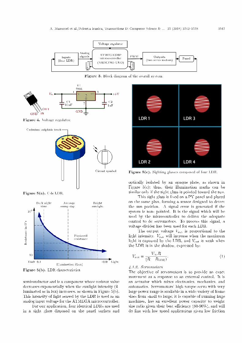
This project involves designing a dual-axis tracker solarpanel prototype, controlled by geared dc servomotors,and analysing its working and performance. It iscomposed of three main parts: Four LDRs formingthe inputs, the Arduino Uno as the ATMEGA328Pmicrocontroller, and two servomotors as the outputswhere the block diagram is represented in Figure 3.Analog signals from the cadmium sul�de LDRs arecaptured by the ATMEGA328P, converted to digitalsignals by Analog/Digital converters, adjusted by twopotentiometers (RTOL, RVIT), and sent to two PWMcontrolled servomotors to move panel towards the sunrays.
Figure 4 shows the LM 7805 positive voltage reg-ulator providing +5 V required by the microcontrollerand most of components of our realization.
The system is designed in two basic parts: themechanical and electrical parts.
4.1. Di�erent components of the electricdesign
This section concerns the components of the solartracker to orient the panel towards solar rays. Thecomponents of the hardware design are four LDRs, theArduino Uno microcontroller, and two servomotors.
4.1.1. PhotoresistorLight-Dependant Resistor (LDR) or Cds photocell, asshown in Figure 5(a), is composed of a high resistivity
A. Mansouri et al./Scientia Iranica, Transactions D: Computer Science & ... 25 (2018) 3542{3558 3545
Figure 3. Block diagram of the overall system.
Figure 4. Voltage regulator.
Figure 5(a). Cds LDR.
Figure 5(b). LDR characteristics.
semiconductor and is a component whose resistor valuedecreases exponentially when the sunlight intensity (il-luminated as in lux) increases, as shown in Figure 5(b).This intensity of light sensed by the LDR is used as ananalog input voltage for the ATMEGA microcontroller.
For our application, four identical LDRs are usedin a sight glass disposed on the panel surface and
Figure 5(c). Sighting glasses composed of four LDR.
optically isolated by an opaque plate, as shown inFigure 5(c); thus, their illumination marks can besimilar only if the sight glass is pointed toward the sun.
This sight glass is �xed on a PV panel and placedon the same plan, forming a sensor designed to detectthe sun position. A signal error is generated if thesystem is non- pointed. It is the signal which will beused by the microcontroller to deliver the adequatecontrol to dc servomotors. To process this signal, avoltage divider has been used for each LDR.
The output voltage Vout is proportional to thelight intensity. Vout will increase when the maximumlight is captured by the LDR, and Vout is weak whenthe LDR is in the shadow, expressed by:
Vout =Vin:R
(R+RLDR): (1)
4.1.2. ServomotorsThe objective of servomotors is to provide an exactmovement as a response to an external control. It isan actuator which mixes electronics, mechanics, andautomatics. Servomotors' high torque servo with verylarge power range is available in a wide variety of framesizes from small to large; it is capable of running hugemachines, has an excellent power capacity to weightsize ratio given their best e�ciency (80-90%), and willdo �ne with low speed applications given low friction

3546 A. Mansouri et al./Scientia Iranica, Transactions D: Computer Science & ... 25 (2018) 3542{3558
Figure 6. Servomotor blocks.
Figure 7. Di�erent parts of the servomotor.
and the correct gear ratio leading to a very low heatproduction, vibration, and very little noise.
The servomotor in Figure 6 is an assembly of threebasic blocks: a body comprising all the mechanics andelectronics, a cable to lead power and the control (refer-ence signal), and a pioneer attached to the servomotor'saxis. Herein, the pioneer is attached to the mechanicalparts to move (arm, wheel, etc.).
This servomotor type requires regulated supplyvoltage of 5 V. This consists of three wires: signal,positive, and ground wires.
It also comprises several internal parts that in-clude the motor and gearbox, position sensor, an errorampli�er, motor driver, and a circuit to decode therequested position. The servomotor only rotates bythe maximum of 180 degrees.
4.1.3. The internal servomotor structureThe servomotor used in this project is an assemblyof four parts: an electrical dc motor, a gearbox, aposition-sensing device which is usually a potentiome-ter, and an electronic card to control and assess themotor.
The servomotor body is composed of an electroniccard receiving the reference signal to do the assessment.This card controls an electrical dc motor that willdrive the pioneer through the speed-reducing gear, asillustrated in Figure 7.
The gearbox has two functions:
- Reducing the speed to provide an accurate trackingof relative position of the servomotor and avoidingany system damage when movement is driven by itsspeed if it is very high;
Figure 8(a). Motor angular speed versus supplyingvoltage.
- Increasing the torque by its mechanical movementof rotation. At an instant t, if we decrease speed leaving the same mechanical power Pmec, this willincrease torque T .
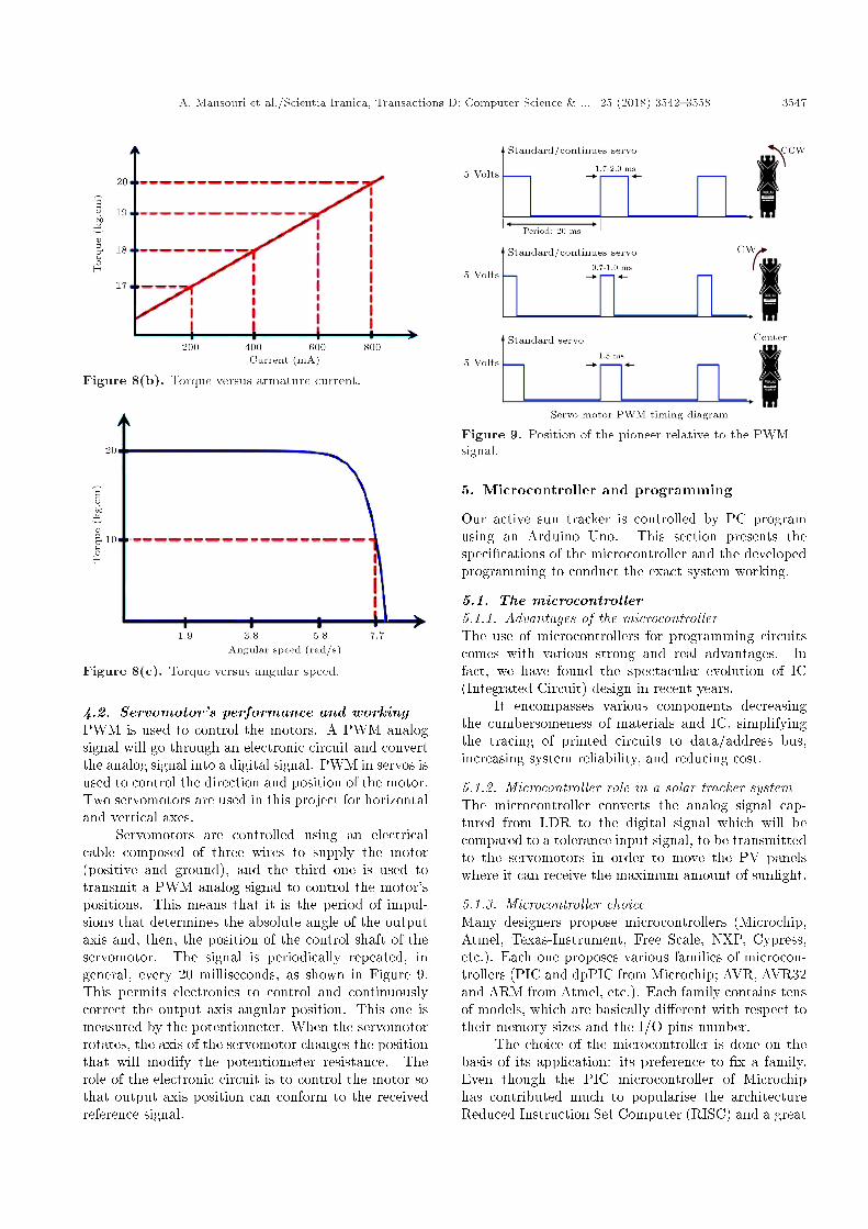
Figure 8 shows a dc servomotor response ofrotating speed via supplying voltage, = f(U),electromagnetic torque via the armature current, T =f(Ia), and torque via angular speed, T = f().
Speed and current are related to supplying voltageand electromagnetic torque, respectively. Hence, for agiven �xed speed, if our system increases the mechani-cal power to move a heavier load (solar panel weight),this will increase current (considering that U and remain constant and electrical power, Pel = U:I, mustbe equal to mechanical power, Pmec = T:, all internallosses are neglected). Since the consumed energy bythe system is generated by the panel itself, to improvee�ciency, power consumption of the solar tracker isreduced since the servomotors supply the amount oftorque just su�cient enough to move it (its mass isabout 250 g).
Figure 8(a) shows angular speed, , of the ser-vomotor changed with the output voltage, U , of thedrive unit. The speed, , starts obviously at zero(servomotor at rest) to reach its maximal value by7.8 rad/s. It is observed that increases in a linearmanner with voltage U to stabilize at an approximatespeci�c value for 5 V.
Figure 8(b) shows the evolution of torque, T , viacurrent, I. The drive unit controls the output torquelinearly, starting at TL = 16:3 kg cm, to increase withcurrent.
Figure 8(c) shows the evolution of T via . it isnoticed that the servomotor keep its torque value evenwhen its speed increases; however, when the motorreaches its nominal speed of 7.7 rad/s, servomotorssupply the amount of torque (10 kg.cm) just su�cientenough to move it.
A. Mansouri et al./Scientia Iranica, Transactions D: Computer Science & ... 25 (2018) 3542{3558 3547
Figure 8(b). Torque versus armature current.
Figure 8(c). Torque versus angular speed.
4.2. Servomotor's performance and workingPWM is used to control the motors. A PWM analogsignal will go through an electronic circuit and convertthe analog signal into a digital signal. PWM in servos isused to control the direction and position of the motor.Two servomotors are used in this project for horizontaland vertical axes.
Servomotors are controlled using an electricalcable composed of three wires to supply the motor(positive and ground), and the third one is used totransmit a PWM analog signal to control the motor'spositions. This means that it is the period of impul-sions that determines the absolute angle of the outputaxis and, then, the position of the control shaft of theservomotor. The signal is periodically repeated, ingeneral, every 20 milliseconds, as shown in Figure 9.This permits electronics to control and continuouslycorrect the output axis angular position. This one ismeasured by the potentiometer. When the servomotorrotates, the axis of the servomotor changes the positionthat will modify the potentiometer resistance. Therole of the electronic circuit is to control the motor sothat output axis position can conform to the receivedreference signal.
Figure 9. Position of the pioneer relative to the PWMsignal.
5. Microcontroller and programming
Our active sun tracker is controlled by PC programusing an Arduino Uno. This section presents thespeci�cations of the microcontroller and the developedprogramming to conduct the exact system working.
5.1. The microcontroller5.1.1. Advantages of the microcontrollerThe use of microcontrollers for programming circuitscomes with various strong and real advantages. Infact, we have found the spectacular evolution of IC(Integrated Circuit) design in recent years.
It encompasses various components decreasingthe cumbersomeness of materials and IC, simplifyingthe tracing of printed circuits to data/address bus,increasing system reliability, and reducing cost.
5.1.2. Microcontroller role in a solar tracker systemThe microcontroller converts the analog signal cap-tured from LDR to the digital signal which will becompared to a tolerance input signal, to be transmittedto the servomotors in order to move the PV panelswhere it can receive the maximum amount of sunlight.
5.1.3. Microcontroller choiceMany designers propose microcontrollers (Microchip,Atmel, Texas-Instrument, Free Scale, NXP, Cypress,etc.). Each one proposes various families of microcon-trollers (PIC and dpPIC from Microchip; AVR, AVR32and ARM from Atmel, etc.). Each family contains tensof models, which are basically di�erent with respect totheir memory sizes and the I/O pins number.
The choice of the microcontroller is done on thebasis of its application: its preference to �x a family.Even though the PIC microcontroller of Microchiphas contributed much to popularise the architectureReduced Instruction Set Computer (RISC) and a great

3548 A. Mansouri et al./Scientia Iranica, Transactions D: Computer Science & ... 25 (2018) 3542{3558
deal of information in the world of microcontrollers andin the related literature has been devoted to informaticsarchitectures, they are not the only circuits in the mar-ket. The microcontrollers of AVR family from Atmel,to which this paper is dedicated, use this architectureand, hence, bene�t from various advantages.
The AVR family has many advantages: inex-pensive, low-energy consumption, and a good supportmulti-platform. They are successful, given the follow-ing speci�cations:
(a) Easy C++ programmation for most basic func-tions;
(b) Low cost and large availability;(c) Low-energy consumption.
5.1.4. ATMEGA microcontrollerThe microcontrollers of the family ATMEGA, inCMOS technology, are models of 8-bit AVR based onarchitecture RISC. When instructions are executed ina simple clock cycle, the ATMEGA realizes operationsreaching 1 MIPS by MHZ allowing for simple systemsdesign and low-energy consumption.
5.1.5. Structure of an ATMEGA microcontrollerThe ATMEGA328P microcontroller is characterized bythe following particularities:
� A Flash Memory of 32 KB for program storage;� A SRAM Memory of 2 KB for variables storage;� An EEPROM Memory of 1 KB for permanent robot
parameters storage;� Technology RISC (one instruction per clock cycle)
presenting a power of 20 Million Instructions PerSecond (MIPS) for a clock frequency of 20 MHz;
� An UART (Universal Asynchronous Receiver/Transmitter) compatible RS232 for the communi-cation with the PC;
� I2C bus for the communication with the componentsI2C;
� An analog/digital converter ADC of 6 channels of10 bits;
� Supplying voltage of 2.7 V to 5.5 V.
5.1.6. SynopsisFigure 10 shows the synopsis of the internal hardwarearchitecture of the ATMEGA328P microcontroller.
5.1.7. Pins descriptionIt is an IC of 28 dual in-line pins shown in Figure 11in which 14 are the digital input/output, of which 6are PWM outputs, 6 are analog inputs, a 16 MHzquartz crystal oscillator, an ICSP (In Circuit SerialProgramming) header, an USB connection, a powerjack, and a reset button. Each pin function is describedbelow:
� VCC: supplying voltage (+3 V to +5 V);� GND: ground;� Port B (PB7... PB0): it is a bidirectional I/O port
of 8 bits with internal pull-up resistors chosen foreach bit;
� PB6/XTAL1: External oscillator ampli�er input orfree for internal clock;
� PB7/XTAL2: Output of the oscillator ampli�er;� Port C (PC5... PC0): It is a bidirectional I/O port
of 7 bits with internal pull-up resistors selected foreach bit;
� PC6/RESET: Released by falling front maintainedfor more than 50 ns producing the reset of micro-controller, even if the clock is at rest;
� Port D (PD7... PD0): The port D is a bidirectionalI/O port of 8 bits with internal pull-up resistorschosen for each bit. It is used as a USART andinputs for external interruptions;
� AVcc: It is supplying voltage to the pin for the A/Dconverter which must be connected to Vcc via lowpass �lter to avoid parasites;
� AREF: It is the analog reference input for the A/Dconverter with a voltage of 2 V to AVcc with low-pass �lter.
5.1.8. OscillatorThe external quartz crystal oscillator is connected toXTAL1 and XTAL2, as shown in Figure 12, to run themicrocontroller. Crystal type Quartz frequency is from4 to 16 MHZ or ceramic resonator.
Using the external quartz oscillator, a capacitivedamper of about 12 to 22 pF must be connected, asshown in Figure 12.
5.1.9. A/D Converter (ADC)The analog to digital converter integrated into theATMEGA comes with very interesting speci�cationssuch as a 10-bit resolution and 6 simultaneous inputs.This ADC converts the analog voltage to digital signalcoded on a 10-bit resolution described by resolutionEq. (2):
Resolution =�
Vin
VA:ref� 1024
�� 1: (2)
5.2. Design of the solar tracker control circuitA dual-axis tracker based on four identical LDRs wasconstructed and tested to set the optimal values of po-tentiometers RVIT and RTOL, shown in both Figure 3and Figure 13. The RTOL tolerance was calculatedin terms of the angle between the upside couple of(LDR1, LDR3) and downside couple of (LDR2, LDR4)sensors. After some initial and trial error testing,the optimal angle between these photo-resistors was

A. Mansouri et al./Scientia Iranica, Transactions D: Computer Science & ... 25 (2018) 3542{3558 3549
Figure 10. Synopsis of the ATMEGA328P.
evaluated experimentally to set the tolerance voltagevalue TOL. Precise results were found because thesystem was working in a close-loop system, whichis the conventional control method of sun trackingsystems by the photo sensors. The photo sensorsare used to discriminate the sun's position and, then,send the proper analog electrical signals, convertedto the digital signal, proportional to controller error,which actuates the motors to track the sun [17,28]. Acircuit scheme of the designed system for horizontaland vertical axes is shown in Figure 13. When thesun moves to the east or to the west, either the couple
(LDR3, LDR4) or (LDR1, LDR2) will receive morelight, transforming the collected solar light intensity toelectrical voltages VLDR3,4 or VLDR1,2 using the voltagedividers (Eq. (1)). Then, they are sent to ADC ports(Pc0, Pc1) for the altitude angle or ports (Pc2, Pc3) andfor the azimuth angle tracking to the microcontrollerto make a comparison with the tolerance input signalTOL sent to ADC port (Pc5) to control servomotors.These ports perform the orientation of the PV paneltowards the sun. Rotation directions for the azimuthand altitude angles tracking the respective horizon-tal (H) and vertical (V ) motors are controlled by

3550 A. Mansouri et al./Scientia Iranica, Transactions D: Computer Science & ... 25 (2018) 3542{3558
Figure 11. ATMEGA328 typical pins.
Figure 12. Oscillator circuit.
using two di�erential ampli�ers (op-amp-H, op-amp-V). Couples (VLDR3,4, VLDR1,2) and (VLDR1,3, VLDR2,4)voltages are sent to the microcontroller for averagecomputation and comparison with TOL. According tothe average di�erences between the voltages from LDRcouples, dVert = jmean(VLDR1,3 � VLDR2,4)j or dHoriz =jmean(VLDR1,2 � VLDR3,4)j are bigger or smaller thanthe �xed value TOL; the proper logic signals are sent tothe errors op-amps to drive the dc motors. The width ofa PWM control signal shown in Figure 9, generated byusing AVR timers, determines the absolute angle of theoutput axis and, then, the position of the control shaftof servomotors. When the motors rotate, H and Vaxes change the positions that will accordingly modifythe potentiometers' resistance (position sensors of theassessed electronic card in Figure 7) mounted on theshafts and provide H and V with feedback voltages.They will be compared to PWM control signals todetermine the positions of the dc motors. Finally,H-motor and V -motor are turned in such directionsas clockwise (cw) or counter-clockwise (ccw) that theabsolute values of dHoriz and dVert become less than theTOL value, and the motors then stop. When the lightsensors have the same amount of resistance values (i.e.,for the same rate of light), the error ampli�ers give thesame output (0 V ) (i.e., the sight glass in Figure 5(c)
is pointed towards the sun), and since the potentialdi�erence at the motor terminals is zero, the panel doesnot rotate.
The logic ISIS Proteus is used to simulate ourmontage in Figure 13. The assemblage of di�erentparts of the system is presented on the global electricscheme of the installation, represented as follows.
The optimal value of potentiometer RVIT is setbased on the weight of the PV panel. For our system,RVIT is �xed to 2.5 k.
If a very small value of the tolerance is chosen,e.g., TOL=0.0001 V, our panel surely oscillates. Po-tentiometer RTOL will be taken which has a toleranceof 0.5 V for a proper working of our system.
5.3. Developing environmentThe compiler gcc-avr has been chosen which is compat-ible with the most popular platforms (Windows, Linux,and Mac).
To transmit the software PC program to theAtmega328p microcontroller, conversion USB seriesmodule must be used; it is the FTDI Basic Breakoutin the same card comporting a microcontroller notedArduino Uno.
Arduino Uno developing environment is a Javamulti-Platform application, used as a code editor anda compiler, to transmit codes to asynchronous serialliaison using C++ programming language.
The Atmega328P pin mapping with Arduino Unoboard is shown in Figure 14 for its programming usingC++ language illustrated in Appendix A.1.
6. Various steps of the mechanical design
This section presents the design of the mechanical partsadopted for the solar tracking mode working on thebasis of horizontal and vertical directions of varyingangles from 0� to 180� and from 0� to 90�, respectively.

A. Mansouri et al./Scientia Iranica, Transactions D: Computer Science & ... 25 (2018) 3542{3558 3551
Figure 13. Solar tracker control circuit.
The mechanical design consists of rotary joints and twodc servomotors.
6.1. Photovoltaic panel prototypeFigure 15 shows our design as a prototype composed ofa wooden plate. Its size is 460� 285 mm and its massis about 250 g. This woody plate will be �xed by sevenvices in seven points on the vertical axis: three in frontand four behind.
6.2. The sight glassFigure 16 shows the sight glass which is �xed to thephotovoltaic panel prototype and placed on the sameplan. It is composed of four LDRs disposed in crossand optically isolated from each other; consequently,
the light intensities will not be identical only if thesight glass is pointed towards the sun.
6.3. Vertical axisThe vertical axis is realized in wood size of 390 mm, thesame for each side. Dual ball bearing facilitates theirrotation. Figure 17 shows how we have �xed the ser-vomotor HS-645MG standard deluxe on the one side.
6.4. Horizontal axisIt is realized that ball bearing will be in the middle ofthe axis as shown in Figure 18 in order to be able todrive the sole.
6.5. The basisThe axis is realized in wood size of 390 � 390 mm, as

3552 A. Mansouri et al./Scientia Iranica, Transactions D: Computer Science & ... 25 (2018) 3542{3558
Figure 14. Atmega328P pin mapping with Arduino Uno board.
Figure 15. Photovoltaic panel prototype.
Figure 16. Sight glass of the tracker.
shown in Figure 19. Its role is to insure the size andthe stability of the installation.
To orient the panel towards the solar rays, wemust, �rst of all, make the choice of the motors.
The size of the tracker panel prototype is imposedby the torques of servomotors. These constraints have
Figure 17. Vertical axis of the tracker.
Figure 18. Horizontal axis of the tracker.
conducted the design of an experimental tracker wherethe quotations are mentioned in Figure 20 (340 mm�275 mm).
7. Management of system owchart
The global program intended to a programmable cir-cuit is based on a precise idea to satisfy the constructor

A. Mansouri et al./Scientia Iranica, Transactions D: Computer Science & ... 25 (2018) 3542{3558 3553
Figure 19. Tracker basis.
Figure 20. Prototype of the tracker panel.
catalogue and industrial context. This one is generallytranslated through a owchart de�ning the varioussteps of the program.
Basic software designThe basic software owchart of the solar tracker systemis illustrated in Appendix B.
8. Conclusion
The described program satis�ed the control conditionsfor the good working of the system; hence, results areencouraging. In fact, the program repartition allowsto distinguish various realized operations. Instruc-tions were derived from the program guidelines in themethodical repairing of the functions. It facilitatedthe modi�cations which could be made during theseworks. The proposed montage used a limited numberof components which are easy to use and occupieda restricted space which could be integrated into acomplete photovoltaic system. The total cost reachedonly 150 Euros, and the period of realization is about40 days. It has an e�ective contribution to the environ-ment and could be improved. Two degrees of freedomorientation were made able to track the sun position.In our case, the system was tested using the ash-lightof a moving electrical lamp to shine it at the sensors;the tracker followed it around, which was successfulin verifying its e�cient and correct working. Themicrocontroller was used to control exact shaft positionof dc servomotors which ensured the point-to-point
intermittent stable movement. The microcontrollerwas designed to rotate the panel from 0 to 180 degrees.The presented dual-axis solar panel tracking systemkeeps the solar photovoltaic panel perpendicular to thesun throughout the year to improve the e�ciency ofthe system.
As advancements made in photovoltaic track-ers technology have decreased investment prices, thisproject could be extended to power supply �t forisolated villages or farms by mounting highly optimal,large and scheduled moving panels to provide a hugeamount of solar energy. Scheduled tracking must use acomputer program to change the angle of the panelbased on date, time, and its physical location evenunder cloud coverage.
References
1. Finster, C. \University Santa Maria Heliostat" [ElHeliostato de la Universidad Santa Maria], Scientia,119, pp. 5-20 (1962).
2. Saavedra, A.S. \Design of a sun tracking mechanismfor automatic measurement of direct solar radiation"[Diseno de un servomecanismo seguidor solar para uninstrumento registrador de la irradiaci�on solar directa],Memoria, Technical University Federico Santa Maria,Valparaiso, Chile (1963).
3. Abdallah, S. and Nijmeh, S. \Two axes sun trackingsystem with PLC control", Energy Conversion andManagement, 45(11-12), pp. 1931-1939 (2004).
4. Roth, P., Georgiev, A., and Boudinov, H. \Cheaptwo-axis sun following device", Energy Conversion andManagement, 46(7-8), pp. 1179-1192 (2005).
5. Yazidi, A., Betin, F., Notton, G., and Capolino, G.A.\Low cost two-axis solar tracker with high precisionpositioning", Proceedings of the International Sym-posium on Environment, Identities & MediterraneanArea ISEIM'2006, Corte-Ajaccio, France, pp. 211-216(July, 2006).
6. Rustemli, S., Dincadam, F., and Demirtas, M. \Perfor-mance comparison of the sun tracking system and �xedsystem in the application of heating and lighting",Arabian J. Sci. Eng., 35(2B), pp. 171-183 (2010).
7. Eke, R. and Senturk, A. \Performance comparison ofa double-axis sun tracking versus �xed PV system",Solar Energy, 86(9), pp. 2665-2672 (2012).
8. Lazaroiu, G.C., Longo, M., Roscia, M., and Pagano,M. \Comparative analysis of �xed and sun tracking lowpower PV systems considering energy consumption",Energy Conversion and Management, 92, pp. 143-148(2015).
9. Chang, T.P. \Output energy of a photovoltaic modulemounted on a single axis tracking system", AppliedEnergy, 86(10), pp. 2071-2078 (2009).
10. Sefa, I., Demirtas, M., and C�olak I. \Application ofone-axis sun tracking system", Energy Conversion andManagement, 50(11), pp. 2709-2718 (2009).

3554 A. Mansouri et al./Scientia Iranica, Transactions D: Computer Science & ... 25 (2018) 3542{3558
11. Ponniran, A., Hashim, A., and Joret, A. \A design oflow power single axis solar tracking system regardlessof motor speed", Internal Journal of Intergrated Engi-neering, 3(2), pp. 5-9 (2011).
12. Huang, B.J., Ding, W.L., and Huang, Y.C. \Long-term�eld test of solar power generation using one axis 3-position sun tracker", Solar Energy, 85(9), pp. 1935-1944 (2011).
13. Seme, S., Stemberger, G., and Vorsic, J. \Maximume�ciency trajectories of a two axis sun tracking systemdetermined considering system consumption", IEEETrans Power Electron, 26(4), pp. 1280-1290 (2011).
14. Koussa, M., Cheknane, A., Hadji, S., Haddadi, M., andNoureddine, S. \Measured and modelled improvementin solar energy yield from at plate photovoltaicsystems utilizing di�erent tracking systems and undera range of environmental conditions", Applied Energy,88(5), pp. 1756-1771 (2011).
15. Saravanan, C., Panneerselvam Dr., M.A., and WilliamChristopher, I. \A novel low cost automatic solartracking system", International Journal of ComputerApplications, 31(9), pp. 0975-8887 (October, 2011).
16. Mousazadeh, H., Keyhani, A., Javadi, A., Mobli, H.,Abrinia, K. and Shari�, A. \A review of principle andsun-tracking methods for maximizing solar systemsoutput", Review Sustain Energy Ren, 13(8), pp. 1800-1818 (2009).
17. Yilmaz, S., Ozcalik, H.R., Dogmus, O., Dincer, F.,Akgol, O., and Karaaslan, M. \Design of two axessun tracking controller with analytically solar radia-tion calculation", Renewable and Sustainable EnergyReview, 43, pp. 997-1005 (2015).
18. Yao, Y., Hu, Y., Gao, S., Yang, G., and Du, J. \Amultipurpose dual-axis solar tracker with two trackingstrategies", Renewable Energy, 72, pp. 88-98 (2014).
19. Nakano, Y. \Ultra-high e�ciency photovoltaic cells forlarge scale solar power generation", Ambio, 41(2), pp.125-131 (2012).
20. Ghaedi, A., Abbaspour, A., Fotuhi-Friuzabad, M., andParvania, M. \Incorporating large photovoltaic farmsin power generation system adequacy assessment", Sci-entia Iranica, Transactions on Electrical Engineering,21(3), pp. 924-934 (2014).
21. Zerhouni, F.Z., Zerhouni, M.H., and Zegrar, M. \Mod-elling polycristallin photovoltaic cells using design ofexperiments", Scientia Iranica, Transactions on Elec-trical Engineering, 21(6), pp. 2273-2279 (2014).
22. Dattaa, A., Bhattacharyab, G., Mukherjeec, D., andSahad, H. \An e�cient technique for controlling power ow in a single stage grid-connected photovoltaicsystem", Scientia Iranica, Transactions on ElectricalEngineering, 21(3), pp. 885-897 (2014).
23. Yaiche, M.R., Bouhanik, A., Bekkouche, S.M.A.,Malek, A., and Benouaz, T. \Revised solar maps ofAlgeria based on sunshine duration", Energy Conver-sion and Management, 82, pp. 114-123 (2014).
24. Stambouli, A.B. \Promotion of renewable energiesin Algeria: Strategies and perspectives", Renewableand Sustainable Energy Reviews, 15(2), pp. 1169-1181(2011).
25. Adouane, M., Haddadi, M., Touafek, K., andAitcheikh, S. \Monitoring and smart management forhybrid plants (photovoltaic-generator) in Ghardaia",Journal of Renewable and Sustainable Energy, 6(2),023112 (2014).
26. Yacef, R., Mellit, A., Belaid, S., and Sen, Z. \Newcombined models for estimating daily global solarradiation from measured air temperature in semi-aridclimates: application in Ghardaia, Algeria", EnergyConversion and Management, 79, pp. 606-615 (2014).
27. Behar, O., Khellaf, A., and Mohammedi, K. \Com-parison of solar radiation models and their validationunder Algerian climate - The case of direct irradiance",Energy Conversion and Management, 98, pp. 236-251(2015).
28. Bentaher, H., Kaich, H., Ayadi, N., Ben Hmouda, M.,Maalej, A., and Lemmer, U. \A simple tracking systemto monitor solar PV panels", Energy Conversion andManagement, 78, pp. 872-875 (2014).
Appendix A
C++ tracking control programm is shown in FigureA.1.
Appendix B
The basic software owchart of the solar tracker systemis shown in Figure B.1.
Explanation of the owchartWe start with the con�guration and initialization ofI/O ports.
It is the nomination of the type of con�gurationof inputs or outputs ports indicating the used pins.
LDRlt = 0; �! LDR top left,LDRrt = 1; �! LDR top right,LDRld = 2; �! LDR down left,LDRrd = 3; �! LDR down right.
Stand horizontal and vertical servomotors to the fol-lowing angles values:
servoh = 90 degrees; �! stand horizontal servo,servov = 90 degrees; �! stand vertical servo.
After delay times and system start up, compute meanvalues per sensors pair for the four sides shown inFigure (5c):
� Read the analog inputs: Acquire and convert theanalog signal to digital values captured by thesensors;

A. Mansouri et al./Scientia Iranica, Transactions D: Computer Science & ... 25 (2018) 3542{3558 3555
Figure A.1. Tracking control C++ program.

3556 A. Mansouri et al./Scientia Iranica, Transactions D: Computer Science & ... 25 (2018) 3542{3558
Figure A.1. Tracking control C++ program (continued).
� Compute the mean values (means): Compute themean values for each couple of LDRs among thefollowing four sensors (Figure 13).
- Between LDR1 and LDR3 �! Mean value of theup side,
- Between LDR2 and LDR4 �! Mean value of thelow side,
- Between LDR1 and LDR2 �! Mean value of theleft side,
- Between LDR3 and LDR4 �! Mean value of theright side.
� Compute the di�erence values (Di�s):
- Compute the di�erence between the mean valueof the up and down sides to control the verticalmotor;
- Compute the di�erence between the mean valueof the left and right sides to control the horizontalmotor.
� �1 � tol > dvertkdvert > tol: The previousobtained result�Compute di�s� will be comparedto tolerance input signal (tol.). If we obtain an equalvalue, the motor is at rest; otherwise, if we have a
di�erent value, the motor will move to change thevertical angle.
� meanh > meanl; (h: high; l: low): Accordingly,the values of the vertical allow for the correction ofthe vertical system position. The motor will movethe panel toward the side where there is a big value;however, when the reached angle is 180� or 0�, themotor stops;
� �1 � tol > dhorizkdhoriz > tol: The previousobtained result�Compute di�s� will be comparedto tolerance input signal (tol.). If we obtain an equalvalue, the motor is at rest; otherwise, if we havea di�erent value, the motor will move to changehorizontal angle;
� meanl > meanr; (l: left; r: right): Accordingly,the values of the horizontal allow for the correctionof the horizontal system position. The motor willmove the panel toward the side where there is a bigvalue; however, when reached angle is 180� or 0�,the motor stops;
The PV system needs two di�erent pauses: Theshort pause is the delay of the position of the PVPanel relative to the sun ray. We can �x a delay of

A. Mansouri et al./Scientia Iranica, Transactions D: Computer Science & ... 25 (2018) 3542{3558 3557
Figure B.1. Tracking control owchart.

3558 A. Mansouri et al./Scientia Iranica, Transactions D: Computer Science & ... 25 (2018) 3542{3558
30 minutes to avoid wasting of energy, after whichthe panel changes the inclination of 9 or 10 degreesfollowing the new position of the sun.
The long mean pause of 12 h (from 10 h to 15 hdepending on the season) will be at the end of the day,permitting panels to have their initial positions.
Biographies
Abdelhamid Mansouri was born in Sidi-Okba, Al-geria in 1951. He received the DES (Diploma of HigherStudies) degree from the University of Algiers in 1979and the MPhil degree in Electrical Engineering fromthe University of S�etif in 1996. He was an AssistantLecturer at the Department of Physics, University ofAnnaba in 1979, and was an Electrical Engineer inIndustrial Societies Enageo & Elatex from 1981 to1983. Currently, he is a Lecturer at the Depart-ment of Electrical Engineering, University of S�etif-1,where he has been since 1983. Being a member oflaboratory of power electronics and industrial control(LEPCI), his research interests are in the areas ofidenti�cation and optimal control of electrical ma-chines, arti�cial intelligence techniques, and renewableenergies.
Fateh Krim received BSc degree from Claude BernardUniversity of Lyon, France in 1976, MSc and Engineerdegrees in Electrical Engineering from Ecole Centrale,
Lyon in 1979, the PhD from Polytechnic NationalInstitute of Grenoble, France, and the special doctoratefrom University of S�etif, Algeria in 1982 and 1996,respectively. From 1982 to 1985, he was the Head ofIC design Department at CIT-Alcatel, Paris, France.He is currently a Professor of Electrical Engineering atUniversity of S�etif-1, Algeria and Director of laboratoryof Power Electronics and Industrial Electronics. Hismain research interests are systems control, power andindustrial electronics, renewable energies. In these�elds, he has more than 80 papers in internationaljournals and refereed conference proceedings. He isa reviewer in 13 journals. Professor Fateh Krimis a senior IEEE member and a member of IEEEIndustrial Electronics Society, IEEE Power ElectronicsSociety, IEEE Power Engineering Society, and IEEEComputational Intelligence Society. He is the Presidentof IEEE Algeria Section and industrial electronics andindustry applications chapter.
Zakaria Khouni was born in S�etif, Algeria in 1988.He received his Bachelor degree in Electrical Engi-neering (EEA) and his master's degree in IndustrialElectronics from Ferhat Abbas S�etif-1 University, S�etif,Algeria in 2012 and 2014, respectively. He is currentlypursuing his PhD at the Electronics Department atS�etif-1 University's, LCCNS Laboratory. His researchinterests include embedded system technologies, fuzzylogic systems, DSP system, and FPGA cards.