design of a ram accelerator mass launch system
TRANSCRIPT

DESIGN OF A RAM
ACCELERATOR MASS LAUNCH
SYSTEM (EASA-CB-184748) CESlGE CF B BAL1 N89-15965
A C C E L E E A 3 C E MASS LBUNCB SYISIEI! E i n a l BeFort ( k a s h i a g t o n trciv.) 2G6 p CSCL 1 U B
Unclas G3/14 0189652
-.
DEPARTMENT OF AERONAUTICS AND ASTRONAUTICS .
UNIVERSITY OF WASHINGTON SEATTLE, WA 98195
DESIGN OF A RAM ACCELERATOR MASS LAUNCH SYSTEM
FINAL REPORT
Spacecraft Systems Design, AA 420/499C NASANSRA Advanced Space Design Program
Prepared B y
Michael Aarnio Calvin’ h e r d i n g Andrew Berschauer Erik Christofferson Paul Clement Robin Gohd Bret Neely
David Reed Carlos Rodriguez F r m c k Swanstrom Seshu Vadd& Jesse Vickers Jack Wolda LeAnne Woolf
Advisors
Adam P. Bruckner Abraham Hertzberg
Department of Aeronautics and Astronautics University of Washington, FS-10
Seattle, WA 98195
June 6, 1988

ABSTRACT
The viability of any large scale permanent space structure relies on the capability of
being able to launch mass easily and efficiently into orbit. The ram accelerator mass launch
system has recently been proposed to greatly reduce the costs of placing acceleration-
insensitive payloads into low earth orbit.
The ram accelerator, conceived and experimentally demonstrated at the University of
Washington, is a chemically propelled, impulsive mass launch system capable of efficiently
accelerating relatively large masses from velocities of 0.7 W s e c to 10 W s e c . The
principles of propulsion are based upon those of a conventional supersonic air-breathing
ramjet; however the device operates in a somewhat different manner. The payload carrying
vehicle resembles the center-body of the ramjet and accelerates through a stationary tube
which acts as the outer cowling. The tube is filled with premixed gaseous fuel and oxidizer
mixtures that burn in the vicinity of the vehicle’s base, producing a thrust which accelerates
the vehicle through the tube.
This study examines the requirements for placing a 2000 kg vehicle into a 500 km
circular orbit with a minimum amount of on-board rocket propellant for orbital maneuvers.
The goal is to achieve a 50% payload mass fraction.
The proposed design requirements have several self-imposed constraints that define the
vehicle and tube configurations. Structural considerations on the vehicle and tube wall
dictate an upper acceleration limit of loo0 g’s and a tube inside diameter of 1.0 m. In-tube
propulsive requirements and vehicle structural constraints result in a vehicle diameter of
0.76 m, a total length of 7.5 m and a nose-cone half angle of 7’. An ablating nose-cone
constructed from carbon-carbon composite serves as the thermal protection mechanism for
atmospheric transit.
i

Two modes of in-tube propulsion involving ramjet cycles are used in sequence to
accelerate the vehicle to the desired launch tube exit velocity. The two modes that have been
investigated are a thermally choked subsonic combustion mode, capable of accelerating the
vehicle from 0.7 W s e c to 2.5 W s e c , and a mode which utilizes a stabilized oblique
detonation wave for combustion to accelerate the vehicle from 2.5 W s e c to as high as 10
km/sec. An initial acceleration from zero to 0.7 W s e c , required to start the ramjet cycle, is
provided by firing the vehicle into the launch tube using a combustion-driven gas gun. Nine
different propellant mixtures, each at a fill pressure of 33 atm and a fill temperature of 300
K, are utilized in the ram accelerator to achieve the desired velocity. These propellants
consist of methane or hydrogen as the fuel, oxygen as the oxidizer ahd carbon dioxide,
nitrogen or hydrogen as diluents which tailor the heat release and speed of sound of each
mixture. The acceleration of the projectile is kept near the design limit of loo0 g’s at an
average ballistic efficiency of 24% and an average thrust pressure ratio of 14%. The required
total length of the stationary launch tube varies from 3.8 km at 8 W s e c to 6.7 km at 10
km/sec. Using high strength steel as the launch tube material, the wall thickness required for
the thexmally choked portion of the barrel is 12.7 cm while the wall thickness of the oblique
detonation portion is 27.6 cm for the first 2.3 km and 24.8 cm for the remainder (using a
yield safety factor of 3).
.
Once the necessary launch velocity of 8-10 W s e c is obtained, the vehicle traverses
the atmosphere thermally protected by a carbon-carbon ablating nose cone. An aerodynamic
heating analysis was carried out to determine the ablation mass loss and the velocity loss
during atmospheric transit. Both turned out to be small. For example, for a 9 W s e c launch
at the corresponding optimum launch angle of 20°, the vehicle retains 85% of its original
launch velocity and suffers an ablative mass loss of only 1.3%. The drag coefficient
increases from .058 at launch to . l l during the atmospheric transit. The aerodynamic
stability of the vehicle was investigated by using small perturbation theory. The vehicle was
found to be inherently unstable. Angular accelerations on the order of 164 rad/s2 at the 4000
ii

m launch altitude and .16 rad/s2 at 40 km altitude were estimated. Stability augmentation
devices, such as control surfaces or spinning the vehicle to provide the needed stability, will
clearly be required.
After the vehicle exits the sensible atmosphere, an indirect orbital insertion maneuver
with two rocket burns and aerobraking is performed to minimize the required on-board
propellant mass. Analyses based on a proposed parking orbit altitude of 450 km and a final
orbit of 500 km have been carried out. A launch site which offers a launch altitude of about
4000 m and lies very near the equator is proposed at Mt. Kenya in Kenya. The total velocity
change needed from the on-board propellant for a 9 W s e c launch velocity at the optimum
launch angle of 20' is approximately 780 d s . The multi-step orbital maneuver with
aerobraking allows a 40% savings in the orbital velocity change required from on-board
propellant in comparison to a similar orbital maneuver without aerobraking. The optimum
on-board propulsion system using current technology is an MMH-N2O4 bi-propellant rocket
with an Isp of 297 sec and a total mass of approximately 670 kg.
The ram accelerator payload vehicle must structurally withstand an acceleration of
lo00 g's, a maximum pressure of 1000 atm in the subsonic combustion mode and 1667 atm
in the oblique detonation mode (using a 1-D analysis), and temperatures on the order of 3000
- 4000 K for brief periods (-1 second). A vehicle configuration incorporating 'T300/5208
graphite/epoxy resulted in minimum structural mass when approximating the composite
material properties as isotropic. The analysis produced a structural mass of approximately
600 kg for a vehicle length of 7.5 m. A finite element analysis yielded similiar results.
Estimates of the vehicle center of gravity place it 3.8 m behind the nose tip with a moment of
inertia of 6,200 kg/m2 about an axis perpendicular to the axis of the vehicle.
Each area of study was analyzed with the restriction that only current technology be
employed. Considerable effort was also made in designing the vehicle to be reusable. It.is
demonstrated that no technological barrier hinders the development of the ram accelerator
mass launch concept.
iii

PREFACE
In 1980 the Department of Aeronautics and Astronautics at the University of
Washington initiated an undergraduate design program in the field of space systems.
Effective student participation in these space-design-related activities has been integrated as
much as possible with the faculty's NASA-funded research program since the inception of
the course. The inception of the NASAAJniversity Pilot Program in 1985 and the selection
of the University as one of the participants in both the Pilot Program and the formalized
Advanced Space Design Program therefore enabled us to develop these efforts very
productively. The student response has been excellent and the synergism with our research
program highly beneficial.
Our course structure is aimed at exposing the students to a design situation which is
"real world" as much as possible within the University framework. In addition, the course
undertakes the responsibility of teaching the students those aspects of space engineering and
science which would be needed for general space capability. Students are taught the
fundamentals of propulsion, orbital mechanics, reentry physics, nuclear and solar power
systems, structures and thermal management.? The design problems expose the students to a
situation in which they must understand the inter-relationship and complete systems
dependence of the structural components, thermal components, and environmental
constraints particular to space.
The course offering consists of two 10-week academic quarters (Winter and Spring).
The first course (AA420 Space Systems Design) is initially structured as a formal
lecture/discussion series which meets 5 hrdweek. Formal lectures by the instructors and
presentations by guest lecturers fiom industry and NASA provide the students with the
fundamental background they need to carry out their design studies. By the second week of
the quarter, the students are divided into design teams whose responsibility is to address
? The topics of propulsion, orbital mechanics and structures are covered in depth in other departmental courses. In the space design course selected topics in these areas are covered.
i v

specific subsystems of the overall design. As the design progresses, more and more time is
devoted to in-class discussions of the students’ work. Teaching assistants supported by
NASA/USRA funds work with the students and help the instructors with project
management. The results of the design study are presented at the end of the quarter in the
form of formal written reports, one by each of the design groups.
The Spring Quarter offering (AA499C - Independent Studies in Space Systems Design)
is intended to refine and advance the design and to address key problem areas identified
during the previous quarter. The class meets formally three hours a week in group discussion
format. Early in the quarter the students are encouraged to submit papers on their projects to
the AIAA Region VI Student Conference. In all cases to date, the reactions of the judges to
the quality of our students’ papers has been very favorable. At this year’s conference our
students garnered two third-place awards in the undergraduate division. At the end of the
Spring Quarter the students submit a single final report on the overall design and make an
oral presentation as part of the department’s Undergraduate Seminar series.
The instructors are proud of the responsiveness of the students and feel that, while the
students are terribly overworked, they are virtually unanimous in agreeing that this course
provides them with a quality introduction to the world of design. A general competitive
atmosphere is maintained wherever possible as an additional simulation of the real world.
The feedback from the students to the instructors also has proved effective in stimulating the
instructors. In addition, the basic research program carried out by the University has
benefited by the recognition of the practical problems of design as they reflect back through
the program.
The design problem selected during the 1985 instructional period, the first year of the
NASA/University program, was a concept for a 150 kWe solar dynamic space power system
for future space factories, either in a roving mode or in space station orbits. The importmt
condition of this design was that this power unit had to operate in an independent power
package. A particularly significant finding of this study was the ability to combine the liquid
V

droplet heat exchanger concept with thermal energy storage in a unique fashion which tends
to avoid many of the difficulties associated with existing thermal storage concepts.
During the 1986 period, an examination was carried out of future NASA space power
needs, particularly in the high power region, i.e., greater than 1 MW. These studies led the
students to conclude that nuclear power offered the most reasonable approach to such high
power needs. A 3 MWe power system was therefore elected as the subject of the design
study. As we were able to perceive NASA’s power needs, we felt that such high power
systems will be required, particularly under the new thrust being set up by NASA based on
the recent report from the National Commission on Space. One of the particular
recommendations of this group is the utilization of extraterrestrial bodies such as the moon,
Mars, and selected large asteroids as part of the supporting infrastructure for a future space
culture. An important finding of our 1986 project was that space-based nuclear power
systems readily adapt themselves to a surface environment without significant mass
penalties. The liquid droplet radiator was found to be particularly adaptable to the moon due
to the positive aspect of lunar gravity on the droplet collection process.
The project selected in 1987, as well as its continuation during the present academic
year had its roots in the area of unconventional space transportation. Approximately 5 years
ago we embarked on a long-range effort to develop a new propulsive technique, the ram
accelerator, which is capable of both the velocities and the scale necessary for a viable direct-
launch-to-orbit system. The ram accelerator is a ramjet-in-tube concept that makes use of
chemical energy in an innovative manner to accelerate projectiles to superorbital velocities.
With funding from the Air Force we have successfully carried out proof-of-principle
experiments. The capabilities of this approach attracted the interest of NASNOAST
management and resulted in a grant (NAG-1-764), with United Technologies Research
Center as the subcontractor, to explore the engineering feasibility and economic advantages
that such a system may offer NASA. Simultaneously, we selected this topic as the 1987
design study for the NASA/USRA Advanced Space Design Program.
v i

The encouraging results of last years’ feasibility study, coupled with the results of the
work under the separate NASA grant, led to our being invited to participate in a briefing at
NASA Headquarters, in November 1987, on Unconventional Transportation Concepts. The
favorable reception accorded to the ram accelerator concept, together with our advances on
the experimental front prompted us to continue with a more detailed engineering study in our
design course this year. The results of that study comprise the content of this report.
The combination of the USRA program with the NASA program has proved unusually
effective, thereby proving a challenging and rewarding design experience for the students.
As this concept continues to develop, it is expected to remain one that the students will
surely respond to with creativity.
A.P. Bruckner Research Associate Professor
A. Hertzberg Professor
June 6,1988
v i i

ACKNOWLEDGEMENTS
We would like to express our deep appreciation to NASA for selecting the University
of Washington to participate in the NASNniversity Advanced Space Design Program.
Thanks are particularly due to Jack Sevier and Carol Hopf of the Universities Space
Research Association for their skillful management of the Program and for the frequent
informative discussions they had with the instructors, and to Karl Faymon of the NASA
Lewis Research Center for his helpful comments and discussions, for providing the
University with relevant literature and data, and for presenting topical seminars to our
students. We are also indebted to Peter Kaloupis and Gilbert Chew, graduate teaching
assistants, for their contributions and diligence throughout the duration of the course, and to
Dean Brackett and Alan Kull, graduate research assistants, for their assistance with some of .
the computational aspects of the project. Many thanks are also due to Bruce Schmitz, Vice
President for Research, Olin/Rocket Research Company, and to Paul Micheli, formerly with
Aerojet General Corporation, for their very helpful discussions on the design of liquid
and solid rocket propellant systems. We would also like to thank Prof. S. Eberhart of the
University of Washington for his insightful advice on atmospheric transit at hypersonic
velocities.
v i i i
TABLE OF CONTENTS
Abstract
Preface
Acknowledgments
I. Introduction
II. Initial accelerator
III. In-tube propulsion
IV. Atmospheric transit
V. Orbital Mechanics
VI. On-board propulsion
VII. Structural design
VIII. Conclusion
Appendix A: Launch Site
Parre i
iv
v i i i
1
8
29
66
98
124
149
181
183

I. INTRODUCTION
The viability of any large-scale, permanent space station relies on the capability of
launching mass easily and efficiently into orbit. Present systems require the launch vehicle
to carry all the propellant neccessary for launch and this reduces the amount of payload the
vehicle can carry, thus increasing the launch costs to as much as $7000/lb for the space
shuttle. Of prime importance for space stations would be water, propellants, consumables,
and structural material, all of which are capable of withstanding high accelerations. Thus,
research has turned toward the potential use of impulsive mass launchers, which impart the
needed orbital kinetic energy at the earth’s surface, eliminating the need for any on-board
fuel during launch, except that for orbit circularization. The ram accelerator mass launch
system is an impulsive launch concept conceived at the University of Washington for
launching acceleration-insensitive payloads into a low earth orbit.[ 1,2]
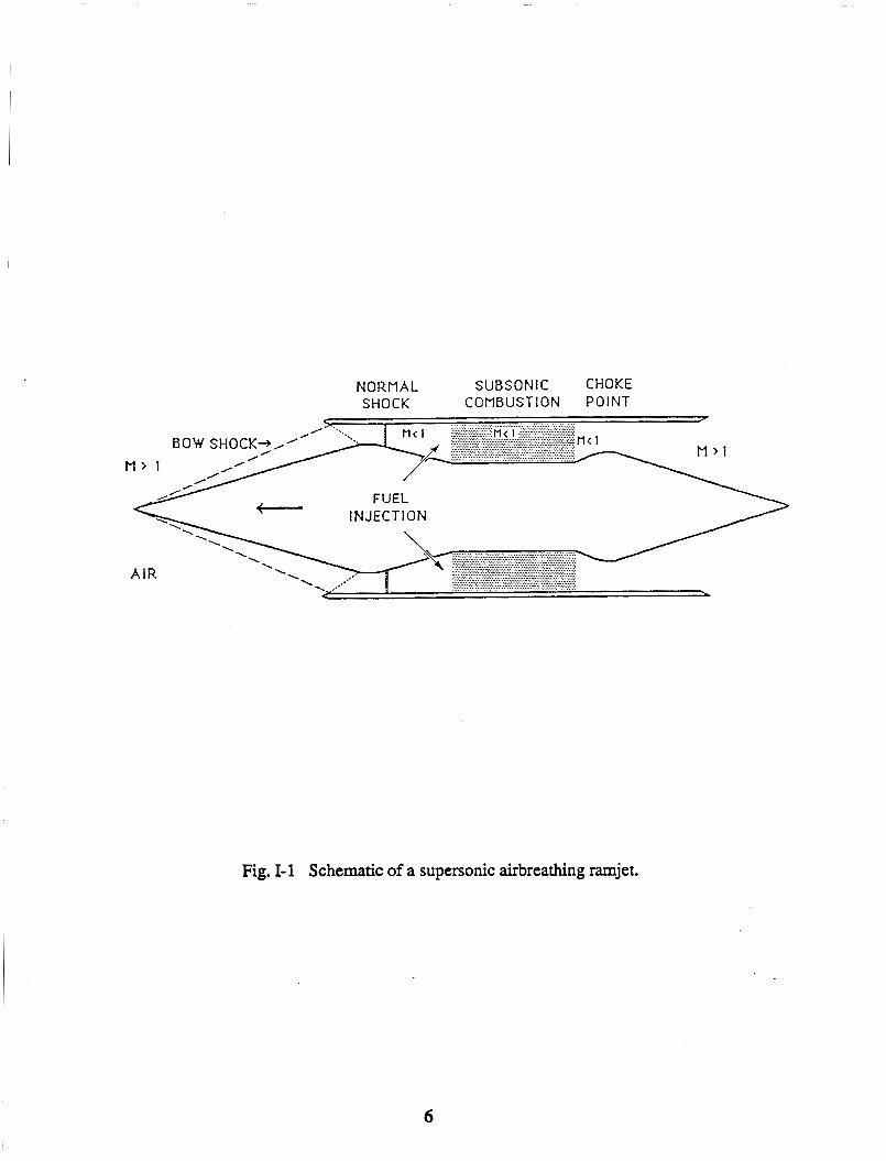
The principles of propulsion of a ram accelerator are based upon those of a
conventional supersonic air-breathing ramjet; however, the device operates in a somewhat
different manner (see Fig. 1-1 and 1-2). The payload carrying vehicle resembles the center-
body of a ramjet and accelerates through a stationary tube which acts as the outer cowling.
The tube is filled with premixed gaseous fuel and oxidizer mixtures that burn in the vicinity
of the vehicle’s base, producing a thrust which accelerates the vehicle through the tube. In
order to accelerate the vehicle to the desired launch tube exit velocity two different modes of
in-tube propulsion involving ramjet cycles are used. The two modes that have been
investigated are a thermally choked, subsonic combustion mode, which accelerates the
vehicle to 2.5 W s e c , and a mode which utilizes a stabilized oblique detonation wave for
combustion at higher velocities. Combined, these two modes are capable of accelerating the
vehicle to a velocity as high as 10 W s e c . An initial combustion-driven, gas-gun type
accelerator is used to impart the necessary initial velocity of 0.7 km/sec for the in-tube
propulsive processes.
In previous work feasibility studies were done and proposals made on how to best
1

design the systems of this concept [1,2]. This year the design program has centered on a
systems analysis based on the earlier proposals.
The design of the ram accelerator mass launch system presented in this report has been
divided into six areas: 1) initial acceleration, 2) ramjet in-tube propulsion, 3) atmospheric
transit, 4) orbital mechanics, 5) on-board propulsion, and 6) structural design of the vehicle
and launch tube. This report details a systems analysis of these five areas. The analysis is
done for the case study of placing a 2000 kg vehicle into a 500 km circular orbit with a
minimum amount of on-board rocket propellant for orbital maneuvers. The goal is to
achieve a 50% payload mass fraction. The proposed design requirements have several self-
imposed parameters that define the vehicle and tube configurations. Due to structural
considerations on the vehicle and tube wall, an upper limit of 1000 g's was imposed on the
acceleration and the launch tube inside diameter was fixed at 1.0 m. In-tube propulsive
requirements and vehicle structural constraints resulted in a vehicle diameter of 0.76 m, a
total length of 7.5 m and a nose-cone half angle of 7'.
The initial accelerator system is detailed in Chapter 11. The ramjet in-tube propulsion,
which deals with imparting the necessary kinetic energy needed for launch, is discussed in
Chapter m. It utilizes the ram accelerator concept which was conceived and experimentally
demonstrated at the University of Washington [3]. The aerodynamics of the vehicle as it
traverses the atmosphere after launch is discussed in Chapter IV. At the high hypersonic
launch velocities of 8-10 km/sec the vehicle experiences severe aerodynamic heating and
forces that will require adequate thermal protection and stability augmentation for controlled
ascent. The thermal protection system used in the study is a carbon-carbon ablative nose
cone. A transpiration cooling scheme was also considered but was ruled out as being too
complex and heavy. The ablative nose cone and large pressure drag act to reduce the kinetic
energy of the vehicle but high velocity retention is crucial for optimization of orbital
maneuvers.
Once beyond the atmosphere orbital maneuvers have to be performed to place the
2

vehicle into the desired low earth orbit. As in any mass launch system, an on-board
propulsion system is required in order to perform these maneuvers. Therefore, it is important
that the orbital maneuvers be devised as efficiently as possible in order to minimize the mass
penalty of the on-board rocket. Previous studies have indicated that a multi-step maneuver
involving aerobraking offers the potential for minimum on-board propulsion system mass
[2]. Therefore, the focus of this study is to integrate a multi-step maneuver with aerobraking
into the ram accelerator launch concept. To increase the flexibility of this launch concept a
parking orbit has been proposed to "store" the vehicle until it is needed at its final
destination, e.g. a space station. The orbital mechanics analysis is presented in Chapter V.
The orbital requirements of the payload vehicle dictate the necessary velocity change
and thrust performance for the on-board propulsion system. The optimization of the mass
fraction of payload limits the size and mass specifications of the propellant system. Various
propulsion systems exist for use on spacecraft, such as solid propellant rockets, liquid
propellant rockets, and other concepts. The selection of a propulsion system which can meet
the design criteria of vehicle mass and volume as well as system costs is treated in Chapter
VI.
During the in-tube acceleration process the vehicle and launch tube experience high
stagnation pressures and temperatures due to the propulsion modes. Of crucial importance to
the feasibility of the ram accelerator launch concept is whether it is possible to design a
vehicle and launch tube capable of withstanding the extreme conditions of launch, while
maintaining the design criteria. Particular areas of concern are at the base of the vehicle
during the thermally choked combustion mode and at the side wall of the vehicle during the
oblique detonation mode. In addition, the vehicle must withstand the peak acceleration of
lo00 g's. Analysis has centered around the use of lightweight, high yield stress
graphite/epoxy composites for the vehicle and high strength steel for the launch tube. These
structural studies are discussed in Chapter VII.
It should be noted that the present design study is not regarded as complete in that the
3

question of cost effectiveness in comparison to other launch methods has not been examined.
However, to keep costs low, only current technology was employed, cheap propellants were
selected, and a considerable effort was made to improve the reusability of the vehicle. Based
on the success of the design and the depth to which the studies could be taken, a clear
direction for system optimization in future studies can be defined.
4

REFERENCES
1. Hertzberg, A., Bruckner, A.P, eds., "The Ram Accelerator Concept: A Method for Direct Launch of Space Cargo to Orbit," Final Report, AA 420/499, NASANSRA Advanced Space Design Program, University of Washington, Seattle WA., June 1987.
2. Bruckner, A.P., and Hertzberg, A., "Ram Accelerator Direct Launch System for Space Cargo," IAF Paper 87-21 1, 38th Congess of the International Astronautical Federation, Brighton, United Kingdom, October 10-17, 1987.
3, Hertzberg, A., Bruckner, A.P., Bogdanoff, D.W., "Ram Accelerator: A New Chemical Method for Accelerating Projectiles to Ultrahigh Velocities", AIAA Journal, Vol. 26, Feb. 1988, pp. 195-203.
5
NORMAL S U B S O N I C CHOKE S H O C K C O M B U S T I O N P O I N T
Fig. 1-1 Schematic of a supersonic airbreathing ramjet.
6

. .
r v = - I
u 3 I- I 0 Z\ 3 Q a ,
m
I I I
t
W d 0
W * I
I I
Ei &
rr 0
? W
7

c Paul Clement
INTRODUCTION
An initial accelerator system must be employed to impart an initial velocity of 700 4 s
to the vehicle so that the in-tube ramjet cycle may properly start. A combustion-driven gas
gun is proposed which uses a stoichiometric methane-air mixture to initially accelerate the
vehicle at a maximum of lo00 g's.
A combustion-driven gas gun uses the pressure created by the combustion of the fuel
to accelerate the vehicle in much the same way a conventional powder gun accelerates a
projectile. Given the vehicle size, mass, acceleration, and post-combustion gas properties
one can determine the required barrel length, combustion chamber length, wall thickness,
mass of propellant and mass of air.
To alleviate gun recoil upon firing, the combustion gases must be diverted through a
muzzle blast deflector. This can be achieved by a simple design with very little increase in
overall ram accelerator length. The performance parameters determined for the initial
accelerator are: vehicle velocity versus the gas escape velocity, ballistic efficiency, and
piezometric pressure ratio.
In addition to determining the basic dimensions, proposals for supporting systems are
presented. Propellant-air mixing in a long tube is proposed as the most efficient method of
delivering well-mixed stoichiometric gases into the combustion chamber. Ignition of the
mixture is accomplished with an axial line ignition source made of tungsten wire. A
closure between the combustion chamber and vehicle in the barrel is needed. This closure
does not open until the required combustion pressure is reached to accelerate the vehicle at
the initial maximum of 1,OOO g's. It is shown that a simple, petalling metal diaphragm
should suffice. Replacement of the diaphragm and vehicle before subsequent launches
presents a unique problem that is solved by having the breech end of the barrel translate to
one side for reloading.
8

THEORY
ial Accelerator R e q . u . u .
The basic requirement of the initial accelerator is to take a vehicle of given mass and
diameter and impart to it a prescribed velocity without exceeding a given maximum
acceleration. Combustion chamber and barrel sizing require the following calculations.*
From Newton's Second Law,
F = m a
The maximum driving vehicle base pressure is then,
P ~ = F / A
and occurs at the beginning of the acceleration process.
Chamber and Barrel Lengths
The sizing of the combustion chamber and barrel is accomplished assuming an
isentropic process after combustion [ 11. The irreversibilities associated with the rapid
expansion of the gases are relatively small. That is, the gradients in an expansion process
tend to decrease, whereas in a compression process they increase. Seigel [ 13 determined
that the isentropic theory over-predicts the vehicle velocity by 2% for vehicle velocities of
the order of the initial sound speed of the gas immediately following combustion.
The required barrel length to achieve a given projectile velocity in a combustion-
driven gas gun is found from the following relation [l],
* The nomenclature follows the list of references in each chapter.
9

x - P -
2 m a0 2
i +1 - + (3)
where the speed of sound immediately following combustion is,
If rarefaction waves reflected from the breech reach the vehicle before it exits the end
of the barrel, the driving pressure, and hence pexformance, is reduced. To ensure this does
not occur, an effectively "infinite" combustion chamber is determined by [ 11,
The pressure at the base of the vehicle may be related to a given vehicle velocity for
the expansion of an ideal gas by [l],
2.1 4.1 -1) Pp / Po = { 1 - up / [2a, / (i -l)]]
The distance travelled down the barrel, xp, for given vehicle velocities (0 to 700 d s )
may be calculated using E!q. 3. A dimensionless distance, q, can then be defined as,
q = xp / Barrel Length (7)
For a given vehicle velocity, a dimensionless velocity, Udp, may be defined as the
ratio of the given local vehicle velocity, up, to the maximum vehicle velocity Urnax ,
10

It can be seen from Eq. 6 that the pressure drops to a value of zero when the gas
velocity reaches a value of 2%/ (V -1). This velocity is called the "escape velocity" [ 13,
If the gas expands to this velocity it can push no more since its pressure has dropped to
zero. The escape velocity is one measure of the usefulness of a propellant. (This relation
is valid for unchambered guns with effectively infinite combustion chambers as is the case
here. An unchambered gun has a combustion chamber I.D. equal to the barrel I.D.). In
practice, the vehicle can rarely obtain more than half the escape speed. This is due to the
fact that at high vehicle speeds the pressure at the base of the vehicle becomes low enough
that gas and frictional resistance and gas pressure ahead of the vehicle equal the pressure
behind the vehicle, thus preventing further acceleration.
The ballistic efficiency of the initial accelerator may be defined as the ratio of the
change in kinetic energy to the chemical energy invested,
The piezometric ratio, Q, is defined as the ratio of peak base pressure to average drive
pressure. It is an important performance parameter because it provides a measure of the
maximum pressure the vehicle and initial accelerator tube must regularly endure versus the
initial accelerator's average driving pressure.
The average pressure over the length of the barrel may be determined from, '
Pave = ( u d 2 m / 2 A L
11

. . e-Air Stoichiometrv and Combus#Jon ProDertieS
To calculate barrel and combustion chamber lengths, as well as required amounts of
methane and air, the gas properties following combustion must be determined.
Combustion of a methane-air mixture in the combustion chamber of the gun is a constant
volume process. The gas properties for this process were determined by use of a computer
combustion code [2]. Input data prior to combustion included reactant temperature,
pressure, molecular composition of the air and methane, and equivalence ratio &e., the
mass ratio of air to methane). Output data following combustion included product
temperature, pressure, molecular composition, ratio of specific heats, and molecular
weight.
From the ideal gas law the specific volume following combustion but before vehicle
movement is,
v = RT,/P, (13)
The chamber length multiplied by the tube area gives the combustion chamber
volume. The volume divided by the specific volume gives a combustion product mass.
From conservation of mass, the amount of combustion products is equal to the amount of
reactants. For a stoichiometric air to fuel ratio, the mass of methane required is,
The partial pressures of methane and air are determined from,
P = n Ru T/ V
12

For simplicity, a uniform thickness is assumed for the entire length of the chamber
and barrel. For safety, the chamber and barrel are designed to withstand detonation
pressures. The tangential stress is largest at the inside radius. If the atmospheric pressure
surrounding the gun is assumed negligible, the largest tangential stress in a thick-walled
cylinder is [3],
RESULTS
Figure 11-1 shows a schematic of the proposed gas gun system. To accelerate a
2,000 kg, 0.76 m diameter vehicle at a maximum of 1,OOO g's a force of 19.6 MN is
required. The required maximum driving pressure is thus 427 am.
The combustion code determined that the stoiciometric mass ratio of air to methane is
17.12. The critical temperature of methane is 191.1 K, above which it will not condense,
regardless of pressure [4]. With a propellant load temperature of 300 K, the methane will
remain in a gaseous state.
The required masses of methane and air are 56 kg and 944 kg, respectively. The
corresponding partial pressures are 5 atm and 42 atm. The total loading pressure of 47 a m
results in a deflagration pressure of 427 atm, as required. The product temperature is 2725
K, molecular weight is 27.39; ratio of specific heats is 1.325 and the resulting sound speed
is 982 m/s. Anticipating that the gun should safely handle accidental detonation of the
stoichiometric mixture, the detonation pressure was determined to be 840 atm.
The combustion chamber length is 42 m and the barrel length is 48 m. Thus, the
combined combustion chamber and barrel length is 90 m.
Figure 11-2 is a plot of Eq. 6 versus Eq. 7. The base pressure remaining after the
13

vehicle reaches 700 m/s is 39% of the initial pressure of 427 atm, or 167 atm.
Consequently, there is still a significant amount of pressure available for further
acceleration.
For a, = 982 m/s and V = 1.325, a gas escape velocity of 6,043 m/s is obtained.
With Umax = 700 m/s, the vehicle needs to achieve achieve only 11.5% of the escape
velocity. Equations 8 and 9 are plotted versus Eq. 7 in Fig. 11-3.
The change in kinetic energy for a 2,000 kg mass accelerating from 0 to 700 m/s is
490 MJ. The heating value for methane alone is 64.3 MJ/kg. With 56 kg of methane
required, the chemical energy invested is 3,600 MJ. Thus, the ballistic efficiency is 14%.
For = 700 m/s and a barrel length of 48 m, the average driving pressure is 222
atm. Thus, the piezometric efficiency is 1.93. The effect of the ambient air in the barrel
ahead of the vehicle is very small, resulting in a velocity reduction of 1.5% (10.5 m/s)
compared to an evacuated barre!l[ 11.
Chamber and Barrel D W
Figure II-4 depicts the cross-sectional dimensions of the chamber and barrel
combination. AIS1 4340 (Nickel-Chromium-Molybdenum) steel is proposed. The ultimate
strength is 1.98 GPa with 11% elongation. Rated yield strength is 1.86 GPa. With a
safety factor of 4.05, the design stress is 459.3 MPa.
Setting Ut equal to 459.3 MPa and knowing the inside radius, r14.38 m, the wall
thickness is calculated to be 7.83 cm. This yields a steel volume of 18.5 m3 and a mass of
144 metric tons based on a steel density of 7,8 18 kg/m3.
PROPOSALS FOR SUPPORTING SYSTEMS
In addition to the combustion chamber and barrel a number of additional systems are
required, such as propellant loading, barrel closures, muzzle brakeblast deflector, ignition
14
system, and replacement of the barrel closure and vehicle.
and J,oadmg
As shown in Fig. II- 1, the air and propellant are mixed in a tube prior to entering the
combustion chamber. Quicker, more thorough mixing and a less complicated loading
procedure is achieved in a tube compared to loading the constituents separately in the
combustion chamber. Tube I.D. is arbitrarily set at 15.24 cm (6 inches) as a size to load
the combustion chamber at a reasonable rate. Concentration fluctuations of less than one
percent can be achieved in a tube length of 100 diameters [5] , i.e. 15.34 m.
Also a consideration will be the presence of air at one a m pressure and in the mixing
tube and combustion chamber prior to fuel loading. This air must be taken into account to
ensure a stoichiometric mixture prior to ignition. The volume of the mixing tube and
combustion chamber is 19.33 m3. This yields 0.785 kg-moles, or 22.7 kg of ambient air.
This figure must be deducted from the 944 kg of air required for a stoiciometric mixture.
Therefore, about 921 kg of air must be added through the air pressure pump.
Since a combustible, stoichiometric mixture exists in the feed tube, it must be
designed to withstand high pressures should accidental ignition occur. An automatic
opening safety valve is installed to relieve pressure, should it significantly exceed loading
pressures. However, the tube thickness is designed to withstand a full 840 atm detonation
pressure. With the same allowable stress and 4.05 safety factor as in the chamber and
barrel, a tube wall thickness of 3.14 cm is obtained. Hence, the weight of the mixing tube
is 1,750 kg.
. . ion S v s t m
The NASA-Ames Research Center currently uses an experimental combustion-driven
shock tube with hydrogen gas as the propellant [a]. The length of the combustion
chamber is 22.86 m and has an I.D. of 0.43 m. These dimensions are of the order of the
size of the initial accelerator proposed here. To discourage the formation of combustion
15

detonation waves, a 0.38 mm O.D. tungsten wire strung down the center of the
combustion chamber is used. Ignition is accomplished by heating the wire with a large
electric pulse derived from a 90 pf capacitor bank charged to 14.5 kV. The suddenly
heated wire thus provides a line ignitioh source. It is proposed to use a similar arrangement
for the initial accelerator described here. However, experiments using a full size
combustion chamber should be conducted to precisely determine combustion behavior and
to ensure reliable, repeatable, and detonation-free operation.
A closure is required between the combustion chamber and gun barrel as well as
between the gun barrel and ram accelerator. The two options include a reusable valve or
moving slide plate and a nonreusable bursting diaphragm. The time between consecutive
launches is orders of magnitude longer than the launch itself. Together with the fact that a
slide plate mechanism would be very heavy, a simple bursting diaphragm is preferred, as
shown in Fig. 11-5.
Using a metallic diphragm, scribing is done along radial lines. The use of a round
shoulder around the circumferential edge of the diaphragm on the low pressure side
promotes clean petalling [7-81. This also helps to ensure that the petals fold back against
the wall. References 7 and 8 found that best results are obtained if a pressure is created
close to that of the natural bursting pressure. Those experiments inserted a plastic
explosive into the grooves of a stainless steel diaphragm. The experiments resulted in
opening times of less than one millisecond with a repeatability of better than 40
microseconds at about 30 atmospheres. Scaling to ram accelerator sizes should be
experimentally tested but would be expected to yield similar results.
To reduce launch tube recoil a multiple stage muzzle blast deflector is employed, as
16

shown in Fig. 11-1. The deflector turns some of the propellant gas backwards causing the
muzzle to be pulled forward, thereby decreasing the rearward force of the recoil.
Initially, the total required exhaust area is arbitrarily set to be five times the gun bore
cross-sectional area of 0.4536 m , i.e. 2.27 m (the exhaust area is arbitrarily picked and
the blast deflector dimensions calculated to see if the dimensions are acceptable with
regards to length and strength. If not, another exhaust area is picked until acceptable
dimensions are achieved).
2 2
For this design ten exhaust stages are initially chosen; the exhaust area is then 0.227
m2 per stage. Following this, if six holes per stage are selected, the exhaust area is 0.047
m* per hole. This results in a hole diameter of 24.5 cm. With six circumfkrential holes per
stage, 91.7 cm is available for the six spaces between the six holes, i.e 15.3 cm between
holes (based on the gun barrel I.D. of 76 cm). These dimensions appear to be suitable with
regards to deflector length as well as the strength of the material between the holes. This
aspect should be analysed in more detail to ensure a safe structure but significant increases
in ram accelerator length will not result in any case.
Assuming steady, one-dimensional flow, the amount of gas diverted at each stage is
proportional to the ratio of exhaust area to total exhaust-plus-bore cross-sectional areas.
The exhaust area of each stage is 1/2 the bore cross-sectional area. Therefore, 1/3 of the
incoming flow is exhausted at each stage.
The ten stages exhaust 98% of the combustion gas. The first stage exhausts 1/3 of
the gases. The second stage exhausts 1/3 of (1 - 1/3) or 2/9 of the gases. The third stage
exhausts 1/3 of (1 - 1/3 - 2/9) or 4/27 of the gases and so on up to ten stages. Using the
above hole diameter and hole spacing, the resulting length of the muzzle blast deflector is
3.03 m.
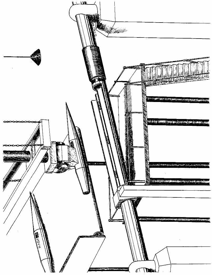
Figure 11-6 depicts a suggested method for diaphragm and vehicle replacement. This
17

method combines movement of a minimum amount of barrel mass with a minimum length
of joints to seal against combustion pressures. A section of the barrel would be translated
laterally to one side by hydraulic rams. The used diaphragm would be removed from the
aft end of the barrel section and a new vehicle inserted, followed by a replacement
diaphragm. The hydraulic rams would then retract and align the barrel section with the rest
of the initial accelerator. Sealing against combustion pressures could be accomplished
using O-rings. The O-rings would lightly seal the barrel upon retraction. Combustion
pressure would then automatically cause the O-rings to seal further.
The alternative would be to translate the 42 m combustion chamber to reload,
somewhat like a conventional cannon. Clearly, the mass and size of the combustion
chamber makes that scheme impractical.
CONCLUSION
There exists no fundamental technological barrier to constructing a combustion-driven
gas gun to accelerate a 2000 kg, 0.76 m diameter vehicle to 700 d s . The following are
initial accelerator size requirements as well as fuel-air requirements:
* Combustion chamber length: 42 m
* Barrel length: 48 m
* Chamber and barrel wall thickness: 7.83 cm
* Chamber and barrel mass: 144,OOO kg
* Muzzle blast deflector length: 3.03 m
* Load pressure of methane-air mix: 47 atm
* Mass of methane per launch: 56 kg
* Mass of air per launch: 944 kg
The following are suggested methods and designs to implement the above requirements:
*Propellant-air premixing in a feed tube.
*Line s o m e axial ignition system using tungsten wire.
*Combustion chamber-barrel closure: pre-scored replaceable steel diaphragm.
*Breech end of barrel translates to the side to facilitate diaphragm and vehicle
18

replacement.
The effect of air in the barrel ahead of the vehicle was found to reduce the maximum
velocity a neglible amount. The maximum vehicle speed of 700 m/s is only 11.5% of the
escape velocity of the combustion products. Therefore, the methane-air combustion
products are a suitable "pusher" for these accelerator requirements. The ballistic efficiency
of the initial accelerator is 14% and the piezometric ratio is 1.93.
19

REFERENCES
1.
2.
3.
4.
5.
6.
7.
8.
Seigel, Arnold E., The Theory of High Speed Gu nS, North Atlantic Treaty
Organization, Advisory Group for Aerospace Research and Developement (AGARD),
no. 91, May 1965, pp. 69-79.
Pratt, D.S., Calculation of Eauilibrium Product C omposition Resulting From
Comblastipn of m b o n Fueh, computer program, Department of Mechanical
Engineering, University of Washington, Seattle, WA, 1988.
Baumeister, T., Marks, L.S., Mechanical En Pineers' Handbook, 6th edition,
McGraw-Hill Book Company, New York, 1958, pp. 5-65 to 5-66.
Chemical Rubber Company, CRC Handbook of Chemistry and Phvsics, 46th
edition, The Chemical rubber Company, Cleveland, Ohio, 1965.
Breidenthal, R.E., Department of Aeronautics and Astronautics,
University of Washington, Seattle, WA, private communication, May 1988.
Bogdanoff, D.W., NASA-Ames Research Center, private communication, April,
1988.
Montgomery, R. and Abell, J.H., Metal DiaDhragm Released ExDlosivelv NOLTR
66-77, April 1955.
Memt, D. and Aronson, P.M., --actions on
9' Cone, NOLTR 67-182, January 1968.
20
NOMENCLATURE
A
AF a
a, CE F
AKE
L
m
n
PP P,g
Po Q R
Ru ‘1
r2
T
To
Urnax
udp uesc
V
V
cross-sectional area of accelerator tube
air to fuel ratio (by mass)
acceleration
maximum post-combustion sound speed
chemical energy
force
change in kinetic energy
barrel length
mass
number of moles
vehicle base pressure
average pressure
maximum post-combustion pressure
piezometric pressure ratio
local gas constant
universal gas constant, 0.08205 (liter-am) p
cylinder inside radius
cylinder outside radius
temperature maximum post-combustion temperature
maximum velocity
r (mole-degre-s K)
dimensionless local vehicle velocity with respect to maximum vehicle velocity
escape velocity of a gas
vehicle velocity
volume
specific volume
21

xd XO combustion chamber length
xP 17 ballistic efficiency
Y
ut tangential stress
dimensionless vehicle distance with respect to maximum vehicle distance
distance vehicle travels down the barrel for a given velocity
ratio of specific heats, cp/cv
22

M E W 4 M X a 4 E;
Sg X w
I .
@ $ E M U
c
r;; n n

BARRELLENGTH: 48 m
MAX PRESSURE: 427 am
0.0 0.2 0.4 0.6 0.8 1 .o
Dimensionless Distance: Projectile Distance/Barrel Length
FIG. II-2. VEHICLE BASE PRESSURE vs VEHICLE TRAWL.
24

0.8 l-F 0.6 t
7
J
0.0 0.2 0.4 0.6 0.8 1 .o
Dimensionless Distance: Vehicle Distance / Barrel Length
BARREL LENGTH 48 m
Umax = 700 m/s
Uesc = 6,044 m/s
FIG. 11-3. LOCAL VEHICLE SPEED COMPARED TO GAS ESCAPE SPEED.
25
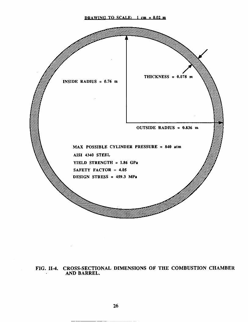
FIG. 11-4. CROSS-SECTIONAL DIMENSIONS OF THE COMBUSTION CHAMBER AND BARREL.

FIG. 11-5. PETALING DIAPHRAGM BETWEEN THE COMBUSTION CHAMBER AND BARREL.
27

crl w
4 X U
z 0
3
0 U
:
5 :
9: 9: c
W
clc 2
w u f 4 a W 9:
3
d Y
n 2 f E W 4
3: a f a \s; n CI
28


III. IN-TUBE PROPULSION Andrew Berschauer
Jesse Vickers
INTRODUCTION
The ram accelerator is a concept developed at the University of Washington for direct
launch of space cargo into orbit [l-61. The propulsion configuration of the ram accelerator
resembles that of a conventional, airbreathing ramjet. The projectile acts as the centerbody,
and the stationary launch tube serves as the outer cowling of the ramjet. The launch tube is
filled with premixed gaseous fuel and oxidizer, and the energy release process, i. e.,
combustion travels with the projectile. In this manner it is possible to specifically tailor the
fueVoxidizer mixtures to each velocity increment, thus serving to increase the overall
performance of the propulsion process. Because it is not necessary for the vehicle to carry
any primary on-board propellant to launch into orbit, a much greater fraction of the total
projectile mass can be allotted for payload [l].
Two modes of ram accelerator propulsion have been investigated: a thermally
choked, subsonic combustion mode (Fig. III-1) to propel the vehicle from 0.7 W s to 2.5
W s , and a 'kuperdetonative" mode (Figs. 111-2 and III-3) which uses an oblique detonation
wave for combustion to propel the vehicle from 2.5 W s up to 10 km/s.
The subsonic combustion mode utilizes thermally choked combustion to provide
thrust to the vehicle. As with a conventional ramjet, an initial velocity is required to start the
propulsive process. Therefore, the vehicle must be accelerated by conventional means, i.e., a
combustion-driven gas gun, to the velocity where the thermally choked mode is operational.
This velocity has been determined to be 0.7 Ws [3]. The composition of the pressurized
gas mixture is chosen such that the vehicle Mach number is sufficient to ensure that the flow
remains supersonic through the throat of the diffuser. The nose cone angle is designed to
ensure that the oblique shock system in the diffuser does not initiate combustion. A weak
29

normal shock is located downstream of the diffuser throat, and the flow behind this shock is
subsonic. The base of the vehicle acts as a flame holding dump combustor and the premixed
propellant gas burns in the tube behind the vehicle. The normal shock is stabilized on the
vehicle by the thermal choking of the flow in the full tube area [3,4]. This propulsion mode
is being experimentally investigated at the University of Washington. Velocities up to 2400
m/s have recently been achieved.
The oblique detonation (superdetonative) mode requires a strong oblique shock wave
to raise the propellant temperature high enough for combustion to occur. The Type I oblique
detonation supersonic combustion mode (Fig. 111-2) uses a reflected bow shock to form the
detonation wave which ignites the propellant mixture. For highest efficiency and assured
detonation, this mode requires that the reflected detonation wave intersect precisely at the
shoulder of the vehicle [6]. It was concluded that this mode is undesirable as it requires a
varying tube radius and/or stringently controlled freestream Mach number for this
requirement to be satisfied as the velocity of the vehicle increases.
The Type I1 oblique detonation mode (Fig. 111-3) operates on the same principle as
the Type I mode, except that a small protuberance located on the vehicle triggers the
detonation wave. This mode requires that the nose cone half-angle be small enough to
ensure that the bow and reflected bow shocks do not ignite the propellant. This design
allows for better flexibility, as the performance need not rely on the precarious placement of
the reflected bow shock. Both oblique detonation drive modes operate at vehicle velocities
which exceed the local propagation speed of a Chapman-Jouguet detonation wave [4-61,
hence the term "superdetonative".
The constraints on designing the propulsion configuration include the tolerable peak
acceleration of the vehicle and the maximum pressures on the projectile and tube wall. The
total mass of the vehicle was set at 2000 kg, and it was desired that 50% of this mass be
devoted as payload mass. Vehicle accelerations were restricted within the limits of 600 g to
1000 g for rapid acceleration while permitting practical structural design. The launch tube
was initially taken to be of 1.0 m internal diameter and the tube fill pressure and temperature
30

were set at 33 atm and 300 K, respectively. The design fill pressure results in the desired
acceleration of this vehicle mass and acceptable pressures on the body and tube wall, while
the temperature is typical ambient temperature. The tube diameter was chosen to
accommodate practical size considerations and desired vehicle performance.
The focus of this chapter is on the analysis of the two ram accelerator propulsion
modes necessary to propel the vehicle from 0.7 km/s to 10 W s . This velocity range spans
the minimum design velocity of the thermally choked combustion mode to the practical
velocity limits of the superdetonative mode.
THEORY
Thermallv Choked Mode
The subsonic, thermally choked mode of combustion (Fig. III-1) is modeled by a one-
dimensional, inviscid, quasi-steady analysis [4]. The gasdynamic conservation equations
(continuity, momentum, and energy) are applied to a control volume framed by stations 1
and 6 as well as the launch tube. Station 1 is located just forward of the projectile nose tip
and station 6 coincides with the plane where thermal choking occurs. These conservation
equations are applied in the frame of reference of a stationary vehicle. Consequently, the
tube wall moves relative to the vehicle with the same velocity as the gas upstream of the
vehicle [4].
The thrust on the vehicle is determined by the fill pressure of the launch tube, the
amount of heat released during combustion, and the properties of the fuel mixture. It can be
shown that the thrust is directly proportional to the tube fill pressure [4]. Diluents can be
added to the propellant mixture to change the vehicle Mach number and the energy per unit
mass; thus controlling the thrust on the vehicle.
The minimum velocity for a given propellarlt mixture is determined by the ratio of
diffuser throat area to tube area and the heat released during combustion. The normal shock
31
must remain behind the diffuser throat for shock stability. As the vehicle Mach number
increases the normal shock moves away from the throat, thus decreasing the vehicle thrust
via increased shock losses and stagnation temperature with constant area heat addition [4].
The maximum vehicle velocity (for a vehicle tapering to a point at its base) is limited, in
principle, by the Chapman-Jouguet (C-J) detonation velocity of the propellant [4]. Because
the vehicle rear cone is truncated to provide a recirculation region for flame retention, the
maximum velocity attainable is approximately 85-95% of the C-J detonation velocity.
Applying the conservation of momentum over the control volume defined by the tube
wall and stations 1 and 6 yields the equation for thrust [lo]:
F = (PA+hU)b - (PA+&U)1- D (1)
Where D is the drag on the body due to skin friction (wave drag appears in the other terms)
and is found from [2]
Combining Eq. 1 with the mass and energy conservation equations over the control volume
results in a non-dimensional thrust on the vehicle (F/PiA) given by the equation [4]:
The ballistic efficiency is defined as the rate of change of projectile kinetic energy
divided by the rate of heat addition to the flow. Using continuity, the ideal gas law, and the
definition of the speed of sound it can be shown that [4]:
32

A parameter useful in determining thrust performance is the thrust pressure ratio [4].
The thrust pressure ratio (TPR) is defiied by the ratio of effective thrust pressure on the
projectile to the maximum cycle pressure. The effective thrust pressure is the thrust divided
by the maximum projectile frontal area [3,4,6].
In addition to the performance parameters listed above it is also very important to
monitor the temperature of the gas along the body. This is especially true between station 4,
just after the normal shock, and station 5, the aft end of the vehicle, where the temperatures
are highest in the uncombusted flow. The purpose of monitoring the temperature is to ensure
that the propellant does not self ignite. For instance, when a hydrogen mixture is used, any
temperature beyond 1200 K risks ignition, whereas methane will ignite around 1500 K [ 111.
In general, by keeping the vehicle Mach number lower than 4.5, temperatures can be kept
low enough so that the gas will not ignite prematurely. The vehicle Mach number should
also be kept above about 2.6 to ensure that the diffuser does not unstart [ll]. The Mach
number is kept within the required limits by dividing the launch tube into several segments
filled with different propellant mixtures whose speed of sound increases towards the muzzle
of the launch tube.
The subsonic thermally choked analysis was performed with the aid of several
computer programs. C. Knowlen's "COMB-3" [7] and A. P. Bruckner's "TCRC11" [8]
programs were utilized for the high velocity, hydrogen mixtures. In addition, C. Knowlen's
program, "CHOKE" [9], was used for methane mixtures. In this manner, appropriate
mixtures for accelerating the projectile between the mentioned velocity limits were
determined.
Obliaue Detonation Mode
Oblique detonation is a complex combustion process, however, this process can be
effecGvely modeled by assuming that complete combustion and heat release take place
instantaneously in a thin region directly behind the oblique shock wave. This approximation
33

is actually quite good and was used in the calculations [12]. The compression across the
detonation wave raises the propellant temperature sufficiently so that combustion occurs
immediately. Since the vehicle is travelling at superdetonative speeds, i. e., faster than the
local speed of propagation of a C-J detonation wave, the detonation wave occurs at an
oblique angle, allowing the flow to remain supersonic over the entire body.
After the thermally choked mode reaches its upper velocity limit of approximately
2.5 Ws, the oblique detonation mode is used. Transition from thermally choked to oblique
detonation mode is affected by a sudden change in propellant mixtures. The oblique
detonation mode’s mixture has a much lower speed of sound than the preceding thermally I
choked mixture, thus causing the Mach number to suddenly increase, resulting in rapid
transition. Mixtures must be chosen so that the freestream velocity of the projectile is faster
than the C-J detonation velocity and combustion occurs immediately behind the oblique
detonation wave generated by the protuberance on the body.
The pressure distribution on the vehicle results from the flow characteristics over the
body. The flow is initially compressed by the bow shock and the reflected bow shock.
Further compressive shocks also occur but are partially canceled by the expansion fan over
the shoulder of the front end. The flow then passes over the body’s constant area portion
until it reaches the oblique detonation wave, across which a large pressure rise results from
the oblique shock and the supersonic heat addition. The pressure on the body then decreases
as the flow passes through the expansion fan which is characteristic of detonation waves
[ll]. After detonation of the propellant mixture by the oblique detonation wave, the flow
passes through the reflected shock from the detonation wave which raises the pressure, and is
expanded supersonically over the rear of the projectile resulting in thrust on the vehicle [6].
Predetonation of the mixture can occur if the temperature after the bow or reflected
bow shock is too high (1200 K) [3]. Predetonation would cause higher pressure on the front
of the body than on the back, i.e., negative thrust. To prevent this, the nose cone angle has to
be small enough to keep the temperature jump across the bow shocks low, yet high enough
34

so that when the flow hits the protuberance, a detonation wave forms. A nose cone half-
angle of 7-10' works well for this purpose [2] and has the added advantage of low
aerodynamic drag. An angle of 7' was used in this analysis.
As defined, the thrust pressure ratio (TPR) is the ratio of the effective thrust pressure
to the peak pressure in the cycle. This peak cycle pressure occurs on the barrel wall,
immediately following the reflected detonation wave.
A FORTRAN program [6,13] was used to calculate the performance of the oblique
detonation mode. For simplicity the flow is assumed to be isentropic up to the oblique
detonation wave. Here, the equations of continuity, momentum, and energy are applied
across the detonation wave, with a heat addition term added to the energy equation. The
flow calculations are performed assuming an ideal gas with one set of values for molecular
weight and specific heat ratio before combustion and a second set after [6]. The
approximation of isentropic compression over the forebody of the vehicle, up to the
detonation wave, affects the results in that the accelerations and efficiencies will be
somewhat overestimated and the TPR will be somewhat underestimated because no bow
shock losses are included. This assumption, however, is valid as a first approximation, and
leads to results very close to those of more sophisticated flow models [14].
A more complex, two-dimensional, CFD code [ 151 was used to c o n f m the results of
the 1-D code. The flow over the body was modeled at one chemistry and freestream
velocity. This program was not used extensively in the analysis because of the extreme
computational time requirements (typically 80 hours of CPU time on a DEC Microvax 11
computer).
The thrust is calculated using the momentum equation (Eq 1). Both the vehicle's
acceleration and the peak cycle pressures increase linearly with increasing tube fill pressure
[4]. From the accelerations, the launch tube length is calculated by simple kinematic
equations applied over specified velocity increments.
With increasing tube
stronger structure to support
fill pressures, rising peak pressures on the body require a
the increased loading; hence, a compromise between higher
35
accelerations and a larger, heavier structure is required. Lowering the tube fill temperature
increases the density of the mixture, giving an increase in thrust; however, temperature
manipulation is not a practical means for controlling vehicle acceleration. Consequently,
another design compromise needs to be made. If the cone angle is increased the bow shock
becomes correspondingly stronger, resulting in a larger temperature jump across the bow
shock [16]. The larger temperature jump causes predetonation to occur at a lower velocity;
hence, the upper velocity limit of the oblique detonation mode will be lower. Decreasing the
tube diameter while keeping the body the same size increases the peak pressures and lowers
the TPR because the flow is being isentropically compressed into a smaller area. By
changing the propellant mixtures (thereby increasing the speed of sound and the ratio of
specific heats along the launch tube), the performance of the vehicle can be tailored to meet
specific design restrictions.
RESULTS
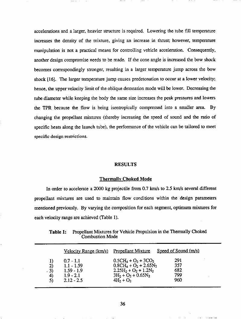
Thermallv Choked Mode
In order to accelerate a 2000 kg projectile from 0.7 km/s to 2.5 km/s several different
propellant mixtures are used to maintain flow conditions within the design parameters
mentioned previously. By varying the composition for each segment, optimum mixtures for
each velocity range are achieved (Table 1).
Table 1: Propellant Mixtures for Vehicle Propulsion in the Thermally Choked Combustion Mode
Velocitv Range - (kds) Prouellant Mixture Speed of Sound (ds)
1) 0.7 - 1.1 O S C b + 0 2 + 3CO2 291
3) 1.59 - 1.9 2.25H2 + 0 2 + 1.2N2 682
5) 2.12 - 2.5 4H2 + 02 960
2) 1.1 - 1.59 0.8Cb + 0 2 + 2.65N2 357
4) 1.9-2.1 3H2 + 0 2 + 0.65N2 799
36

Figure 111-4 shows a plot of acceleration versus vehicle velocity. It can be seen that the
accelerations are kept within the range of 600 to 1000 g, with an average acceleration of 857
g. A transition is made to another propellant mixture as the temperature behind the shock
reaches the design limit of 1500 K for methane and 1200 K for hydrogen (Fig. III-5). Above
these limits, the propellant mixtures can self ignite at the normal shock, resulting in a
detonation wave propagating ahead of the vehicle. This, in turn, would produce negative
thrust on the vehicle--a highly undesirable consequence.
Although the second methane mixture in Fig. 111-5 does not reach its maximum design
temperature of 1500 K, it was determined that higher accelerations, ballistic efficiencies, and
TPR’s could be reached by changing to another propellant mixture prior to attaining this
temperature limit. By optimizing the propellant mixtures, an average ballistic efficiency of
14.4% is achieved for the thermally choked mode. A maximum efficiency of 19.2% occurs
in mixture 2 (Fig. 111-6).
Figure 111-7 shows that the TPR was kept between 30 and 70% over the velocity range
of the thermally choked mode. The average TPR here is 48.5%. The TPR for a given
mixture is not allowed to fall below approximately half of its initial value to ensure that a
maximum thrust efficiency is maintained. This was not of major concern, however, as in
most of the mixtures the temperature design constraint is reached before the TPR falls to half
its initial value.
The Mach number for the vehicle is kept approximately between 2.6 and 4.5 (Fig. 111-
8). As noted earlier the reason for a minimum of 2.6 is to ensure that the flow in the diffuser
does not unstart. Depending on the propellant mixture and the initial velocity, unstarting of
the diffuser occurs in the range of M = 2.3 - 2.6. Figure III-8 also shows a plot of the Mach
number at the throat of the vehicle. Its value is not allowed to drop below approximately 1.5.
The maximum vehicle Mach number of 4.5 corresponds to the shock temperature limit to
prevent detonation of the propellant immediately behind the shock (Fig. 111-5).
37

In Fig. III-9 it can be seen that a maximum static pressure on the vehicle and the wall is
1007 atm and occurs just before the transition between mixtures 2 and 3. The average peak
static pressure is 770 atm on the vehicle and launch tube wall.
Figure III-10 shows a plot of velocity as a function of distance along the launch tube.
Here, it can be seen that the projectile is accelerated from 0.7 km/s to 2.5 km/s within a
distance of 345 m.
Smoother profiles of the performance parameters could be achieved if the number of
mixture segments were increased; however, the ratio of body length to segment length could
not be allowed to exceed one due to the computational methods used (for this analysis a body
length to segment length ratio of approximately 1/5 was used). Alternatively, it might be
possible to fill the tube with a continuously graded mixture composition.
Obliaue Detonation Mode
The lower limit of the velocity range for the oblique detonation mode is defined by the
C-J detonation velocity of the propellant mixture. To ensure combustion, however, a
limiting value of 15 - 20% greater than the C-J velocity was set at the low end of the desired
velocity range. This limit was determined to be 2.4 W s for a detonable mixture of methane,
oxygen, and argon. It was decided, however, that the thermally choked mode of propulsion
would transition to the oblique detonation mode at a velocity of 2.5 W s . This velocity was
used because it fell between the two limiting values for each mode. Also, the acceleration of
the thermally choked mode falls rapidly beyond 2.5 W s . Table 2 shows the mixtures used
for this mode of propulsion and their corresponding velocity ranges as determined by an
analysis based on 1-D flow assumptions.
Table 2: Propellant Mixtures for Vehicle Propulsion in the Oblique Detonation Mode
Calculated Velocitv Range (kmh) Promllant - Mixture Detonation Speed (kds)
1) 2.5 -3.15 cH4+02+5Ar 1.650 2) 3.15 - 4.75 2.4H2 + 0 2 + 2N2 2.723 3) 4.75 -7.2 5H2 + 02 3.510 4) 7.2- 10 8H2 + 02 3.749
38

The mixtures used in this analysis were tailored to meet the given acceleration
parameters while, at the same time, yielding satisfactory efficiencies. Figure III-11 shows
the acceleration profile of the projectile as a function of freestream velocity. It was desirable
to maintain as low freestream Mach numbers as possible (Fig. III-12) in order to minimize
in-tube heating of the vehicle, as projectile heating varies as the square of the Mach number.
Therefore, an arbitrary upper limit of M = 11 was set and changes in mixture were made
primarily to keep the Mach number below this value, as the acceleration does not vary
strongly with vehicle velocity. Some encroachment of this constraint does occur at velocities
in the vicinity of 9 km/s; however, this is near the design exit velocity and the remaining time
of vehicle transit in the tube is small enough that the increased heating effect is negligible,
especially when compared to the ensuing flight Mach numbers of atmospheric transit, which
are well into the hypersonic regime. In Chapter IV the problem of in-tube aerodynamic
heating is treated.
The maximum temperature on the body was found to occur immediately following the
oblique detonation wave and reached a maximum value of 4100 K for mixture 2 (Fig. III- 13). It was found that with the final propellant mixture, the vehicle acceleration did not meet
the established design criteria with a tube diameter of 1.0 m. To remedy this situation, an
investigation into the effects of varying the tube diameter was performed (Figs. III-14 - III- 16).
If the tube inner diameter is decreased, the flow must be compressed into a smaller
annular area; hence, the pressures on the body (Fig. III-14) and tube (Fig. III-15) increase
greatly with decreasing tube diameter and vehicle acceleration improves slightly (Fig. III-
16). In addition to increased acceleration, the ballistic efficiency of the process increases,
and the TPR decreases as the peak cycle pressure increases with decreasing tube diameter. It
was found that an inner tube diameter of 0.9 m yields satisfactory vehicle acceleration while
keeping the maximum pressures on the tube and body within reasonable structural limits.
The smaller tube diameter was used only for the final propellant mixture (8H2 + 02) because
of the inadequate performance of this mixture with the typical tube dimensions.
39
The maximum static pressure on the vehicle (Fig. 111-17) was found to occur
immediately following the oblique detonation wave prior to expansion. This pressure was
calculated to be approximately 1667 atm, occurring during the initial and final phase of
transit (mixtures 1 and 4, respectively). The peak pressure on the barrel wall occurs
immediately following the reflected detonation wave and is 3467 atm. After the detonation
wave the pressure drops abruptly as the flow passes through the expansion wave following
the shock.
Figure 111-18 shows that the Type I1 oblique detonation mode operates at ballistic
efficiencies ranging from 20.1% to 29.6%, and averaging 25.1%. The thrust pressure ratio
(Fig. 111-19) ranges from 8.1% to 14% and averages 11%. These figures compare to an
average ballistic efficiency of 22.7%, and an average thrust pressure ratio of 13.1% for the
Type I oblique detonation mode used in a previous study [2]. It should be reiterated that the
model used for computation neglects the bow shock; hence, the efficiency calculated is
overestimated and the thrust pressure ratio is underestimated due to the omission of shock
losses prior to detonation; however, the error incurred is small [14].
In Fig. ID-20 the launch tube length required for a given exit velocity is shown for
vehicle propulsion from initial acceleration to launch tube exit. For a design exit velocity of
9.0 km/s, a tube length of 5.1 km is required. Of this length, 4.78 km (approximately 93%) is
required for the oblique detonation mode alone. For higher exit velocities, this distance
increases rapidly, as shown. As can be seen, the oblique detonation mode is the dominant
factor in determining overall launch tube length.
2-D CFD Results
The two-dimensional analysis was performed only at a vehicle velocity of 7.2 krri/s
(mixture 5, oblique detonation mode) to confirm the validity of the 1-D analysis. CPU time
40
requirements precluded a full analysis of the oblique detonation propulsion mode over the
entire velocity range of interest.
The 2-D analysis yields accelerations which are 12% lower than what 1-D
approximations predicted. The ballistic efficiency calculated with 2-D approximations is
32.4%, and the thrust pressure ratio is 12.0%. These are 12.1% and 44.6% higher,
respectively, than the 1-D values.
The 2-D analysis also shows the peak pressures on the vehicle and barrel wall to be
1939 and 1872 atm, respectively. These values differ by +18.1% and -46.2%, respectively,
from the 1-D calculations. These differences occur because of the two-dimensionality of the
flow over the vehicle.
The 1-D analysis calculated pressures quite well in the immediate vicinity of the
vehicle (CFD values average a difference of 15% from 1-D approximations); however, near
the tube wall the differences were much greater. As a result, the 2-D value for peak pressure
on the launch tube wall (1872 atm) was used to determine tube wall thicknesses for the
detonation propulsion mode. The 2-D pressure values were chosen since the CFD code
provides a much more realistic description of the flow field. The thermally choked subsonic
combustion peak pressure values are quite accurate, though, since 1-D approximations are
quite good behind the body (where combustion takes place) and since the exact solution for
the pressure here is readily available in closed form (Eq. 3).
CONCLUSIONS
The ram accelerator is a concept designed to efficiently propel acceleration-
insensitive payloads into space. The gasdynamics of the ram accelerator resembles that of a
conventional airbreathing ramjet. The projectile serves as the centerbody of the ramjet while
the outer cowling of the ramjet is provided by the launch tube. The launch tube is filled with
premixed propellants so that the energy release travels with the vehicle, and no on-board
propellant is required. This design allows the propellant mixtures to be graded so that the
performance can be optimized to meet specific design requirements.
41

This chapter has analyzed the propellant mixtures necessary to accelerate a projectile
from 0.7 km/s to 10.0 km/s. A total of nine mixtures and two combustion modes are required
to propel the projectile to the design exit velocity (9.0 km/s). The thermally choked subsonic
combustion mode is used for velocities ranging from 0.7 km/s to 2.5 km/s, and requires 345
m of the accelerator length. The second combustion mode utilized is the Type II oblique
detonation mode. This mode propels the projectile from a velocity of 2.5 km/s to 9.0 km/s
(with the capability for further acceleration), and requires 4.78 km (approximately 93%) of
the total launcher length.
Ram acceleration can be performed with satisfactory efficiency. The thermally
choked mode efficiency averages 14.4%, while the oblique detonation mode averages 25.1%
for an overall average of 24.4%. The overall thrust pressure ratio averages 13.6%. Peak
pressures on the vehicle are 1007 atm and 1939 atm for the subsonic and detonation
propulsion modes, respectively. Also, the peak pressures on the wall of the launch tube are
1007 atm and 1872 atm for these modes.
42
REFERENCES
1.
2.
3.
4.
5.
6.
7.
8.
9.
10.
11.
12.
Bruckner, A.P. and Hertzberg, A., "Ram Accelerator Direct Launch System for Space Cargo," IAF Paper 87-21 1, 38th Congress of the International Astronautical Federation, Brighton, England, October 10-17, 1987.
Hertzberg, A. and Bruckner, A.P., eds., "The Ram Accelerator Concept: A Method for Direct Launch of Space Cargo to Orbit," Final Report, AA420/AA499, NASA/USRA Advanced Space Design Program, University of Washington, Seattle, WA, June 1987.
Bruckner, A.P., Bogdanoff, D.W. and Knowlen, C., "Investigation of Gasdynamic Phenomena Associated with the Ram Accelerator Concept," AIAA Paper 87-1327, AIAA 19th Fluid Dynamics, Plasma Dynamics and Laser Conference, Honolulu, HI, June 8-10,1987,
Hertzberg, A., Bruckner, A.P. and Bogdanoff, D.W., "The Ram Accelerator: A New Chemical Method for Accelerating Projectiles to Ultrahigh Velocities," AIAA Journal, %,195( 1988).
Hertzberg, A., Bruckner, A.P., Bogdanoff, D.W., and Knowlen, C., "The Ram Accelerator and its Applications: A New Chemical Approach for Reaching Ultrahigh Velocities," Proceedings of the 16th International Symposium on Shock Tubes and Waves, Aachen, West Germany, July 26-30,1987, pp 117 - 128.
Knowlen, C., Bruckner, A.P., Bogdanoff, D.W., and Hertzberg, A., "Performance Capabilities of the Ram Accelerator," AIAA Paper 87-2152, AIAA/SAE/ASME/ASEE 23rd Joint Propulsion Conference, San Diego, CA, June 29 - July 2, 1987.
Knowlen, C., "COMB-3," Computer Program for Combustion Analysis of the Thermally Choked Ram Accelerator, Department of Aeronautics & As.tronautics, University of Washington, Seattle, WA, November, 1983.
Bruckner, A.P., "TRCR11," Computer Program for Thermally Choked Ram Accelerator Analysis, Department of Aeronautics & Astronautics, University of Washington, Seattle, WA, February, 1987.
Knowlen, C., "CHOKE," Computer Program for Thermally Choked Ram Accelerator, Department of Aeronautics & Astronautics, University of Washington, Seattle, WA, 1984.
Oates, G.C., Aerothermodynamics of Gas Turbines and Rocket ProDulsion, American Institute of Aeronautics and Astronautics, New York, 1984.
Bruckner, A.P., Department of Aeronautics & Astronautics, University of Washington, Seattle, WA, Private Communication, February 1988.
Pratt, D.T., Humphrey, J.W., and Glenn, D.E., "Morphology of a Standing Oblique ' Detonation Wave," AIAA Paper 87-1785, AIAA/SAE/ASME/ASEE 23rd Joint Propulsion Conference, San Diego, CA, June 29 - July 2, 1987.
43

13. Bogdanoff, D.W., "OBLI2", Computer Program for Type 11 Oblique Detonation Ram Accelerator Analysis, Department of Aeronautics & Astronautics, University of Washington, Seattle, WA, June 1987.
Bogdanoff, D.W., NASA Ames Research Center, Private Communication, February 1988.
14.
15. Bogdanoff, D.W. and Brackett, D., "A Computational Fluid Dynamics Code for the Investigation of Ramjet-in-Tube Concepts," AIAA paper 87-1978, AIAA/ASME/SAE/ASEE, 23rd Joint Propulsion Conference, San Diego, CA June 29 - July 2, 1987.
16. Liepmann, H.W., Roshko, A., Elements of Gas Dvnamics, John Wiley, New York, 1957.
44

a
A
G
Cp D
F
g
m
M
P
4 S
T
U
Y rl
P
NOMENCLATURE
speed of sound
tube cross-sectional area
coefficient of friction
specific heat at constant pressure
drag
thrust
acceleration due to gravity
mass flow rate
Mach number
pressure
heat release due to cormus1
surface area
static temperature
velocity
ratio of specific heats
ballistic efficiency
density
Subscripts
i ith station
1 freestream conditions
.on
6 conditions at point of thermal choking
45

L
3 m 0
A z I
w l
= : 0
n w X
Y ce: e
z
46
U w
W M 3 n LL.- X
0
d a 8
.. d
k CI

F A 5
I
F A 2
s W C e
I 47

I v)
3 m 0
W
e a
/J 48
C 0 .- Y
E cd
C '0
(d C 0
.d Y
Y
4
3
P)
.d 3 0 U U
.. ;
' c (
do crc .-

2
8
x
c! r( + + P4
49

i
(u
5 0 +
. o " + (u - k s
Y
+
d
50

2 F! .-( +
2 v)
c1 \9
8 +
51

0 0 0 6 2 4
0 e9
0 * 0 hn 0
(0 0 0
b 0 0
0 m 50
52
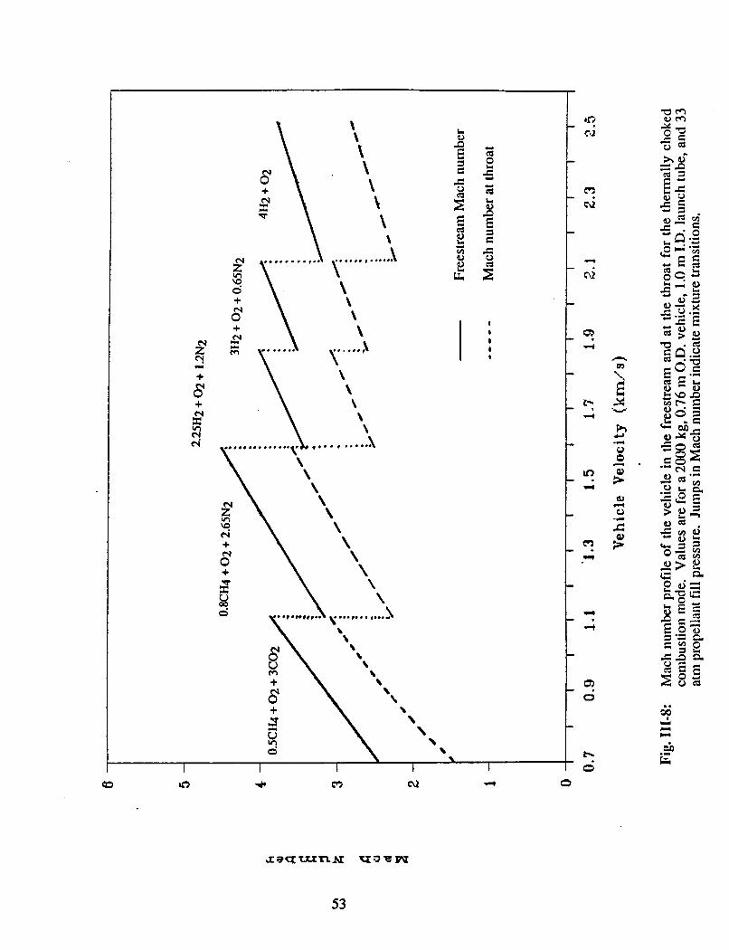
L a) n E
5
E E 2
1 E
5 (d
VI a)
d
L
I
53

54

0 0 m
0 0 N
0 0 -
-
- 0
55

z"
8 c( +
+ N
3 + 8 + P
E 2
II P
I
---- I
I + E
CI
c II
1 I I I I 1 I
d e .
eu d d
d Q)
0
m 0
h CD 0 0
0 1
In 0
56

E 2 n II
I - - - - I
I + E
II GI
rl
c .z: -s c1 0 ea
57
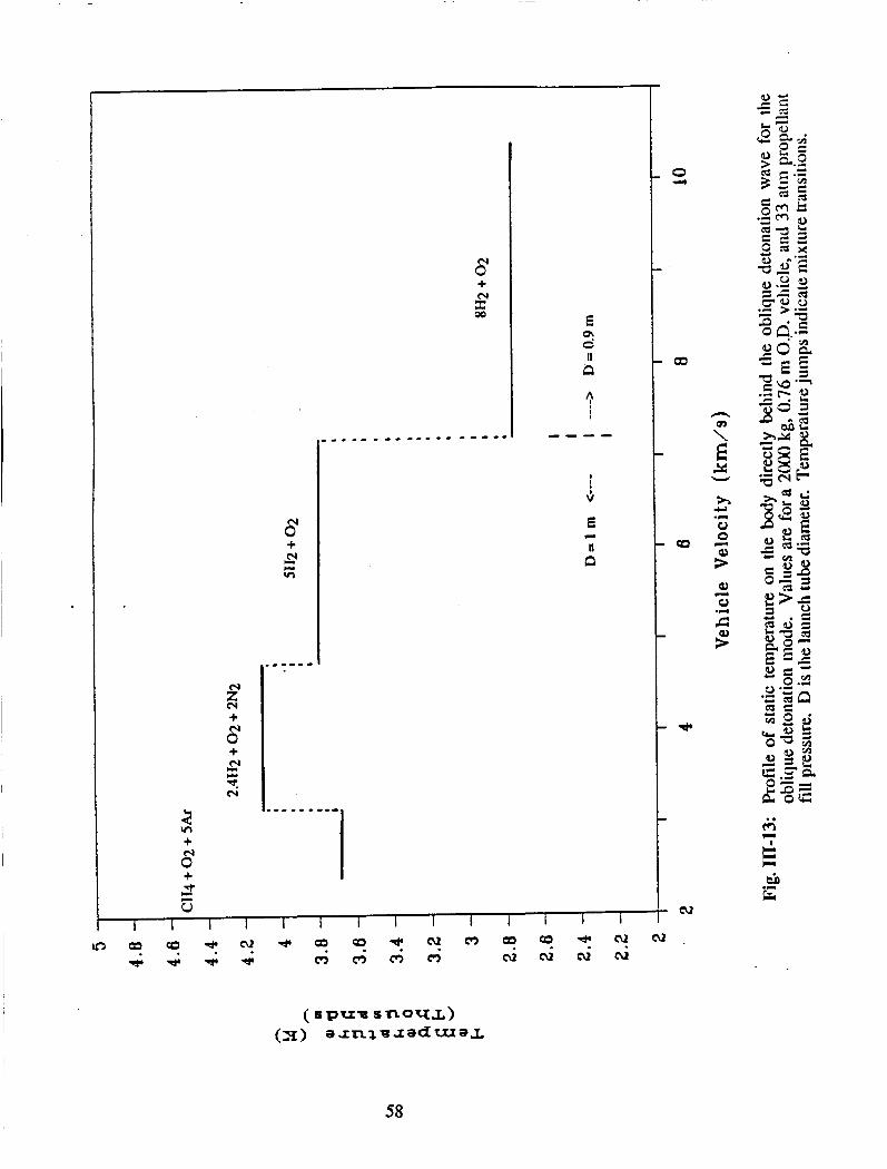
z"
0" e4 +
+ a e4
2
8 VI +
+
0" + 00 E
2 I! P
I
l
I
6 E
P
n II
58
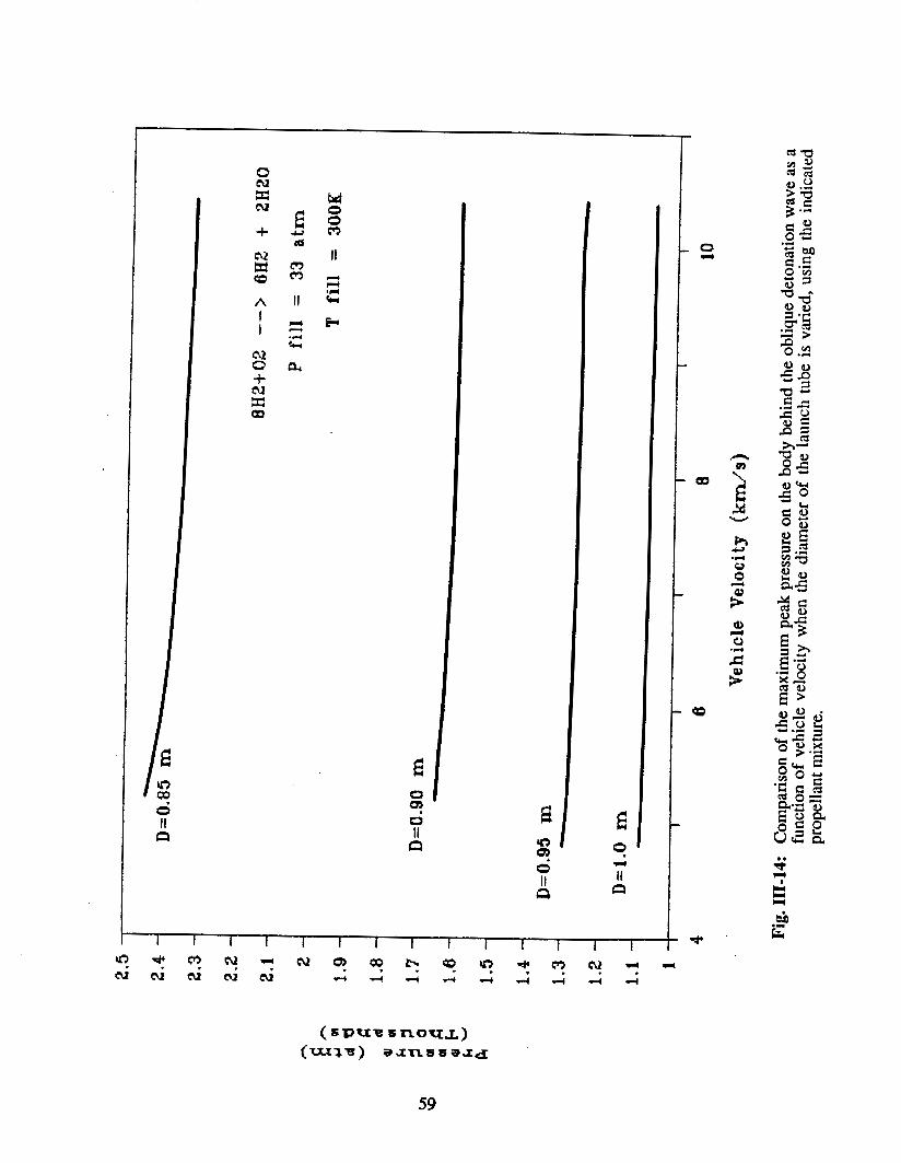
0 N
cv 0 X M
+ - E %
El 01
a 9
~
I I I I I I I I I I I I I I
59

G 0 m 0 I1 CI
a u3 U J
I I I I I I I I I I I I I I I
60

0 m 0 II CI
0 .I)
h m
- 2 X W

4
I . I - - - - I I +
z \ + : \ - N \ +
s \
8 +
2 I" + I S I d z u I
I I I I I 1 I I I I 1 I i I I
62

0 hn d( m
0" + p1
00 t:
3 I
- - - - I I
\i E CI
II n
0 c3
0 02
0 m 0 4
hn .rl

+
+
E 2
It 13
3 I
---- I I
4
n
Y E X
h
W
Y
0 0 .d
R
g * Q)
0 0
.r( c
64

65

IV. ATMOSPHERIC TRANSIT
Erik Christofferson Bret Neely
Fred Swanstrom
INTRODUCTION
The purpose of the atmospheric transit study is to determine the change in velocity
and the thermal protection requirements, and to examine the dynamic stability of the
vehicle from the exit of the ram accelerator tube at 4 km to an altitude of 40 km, at launch
angles ranging from 16' to 30'. As elevated a launch altitude as possible is desired in
order to reduce the atmospheric heating and drag, and thus minimize mass and velocity
loss. An altitude of 4 km is considered to be the most feasible altitude for launch (see
Appendix A). An altitude of 40 km is assumed to be the edge of the sensible atmosphere
due to the low density, the onset of slip flow, and the fact that aerodynamic heating
becomes negligible. The 16' to 30' launch angle constraint is the consequence of
parameters specified by orbital mechanics. Beyond 40 km, an orbital mechanics approach
can be used to follow the progress of the vehicle into low earth orbit, as discussed in
chapter V. The cylindrical, non-lifting vehicle has a nose cone half angle of 7', a diameter
of 0.76 m, and an initial mass of 2000 kg (Fig IV-1).
Upon exit from the launch tube, the vehicle will be traveling at 8 - 10 km/sec which
results in a Mach number range of 25 - 31. These hypersonic velocities will subject the
vehicle to severe aerodynamic heating and forces which will require adequate thermal
protection and stability augmentation for a controlled ascent. Convective heating
dominates the heat input to the nose cone, and radiative heating, even at the high velocities
considered, can be shown to be negligible in comparison to the convective heating.[l] Due
to convective heating alone, the nose of the vehicle will experience severe stagnation
temperatures that are on the order of 9,000 - 14,000 K, even after considering equilibrium
dissociation of the air across the bow shock wave and in the boundary layer.
66

There are a number of possible approaches to the thermal protection problem. One
possibility is transpiration cooling. This method, which involves injecting a coolant
through a porous nose cone to keep the nose at a relatively low constant temperature, was
previously examined.[2,3] Although this cooling method would theoretically render the
vehicle unharmed by the atmospheric heating, leaving it re-usable, transpiration hardware
is heavy, complicated and expensive.
Another method for thermal protection is to employ an ablative nose cone. Ablation
has been defined as a "self regulating heat and mass transfer process in which incident
thermal energy is expended by sacrificial loss of material"[4]. If an ablative nose cone
with low thermal conductivity is used, a large amount of heat can be absorbed through the
chemical charring and sublimation of the ablator; The heat absorbed will not reach the
virgin material below the charred layer of the ablator, thus in effect ablation leaves the
payload portion of the vehicle unharmed. Even though ablation blunts the shape of the
nose cone and destroys the re-usability of the front portion of the vehicle, it will be cheaper
to use ablation, in the long run, due to the manufacturing complications and decreased
allowable payload associated with transpiration cooling hardware [3]. Preliminary studies
have indicated that the mass loss due to ablation is not substantial [5], and thus the weight
of the thermal protection system is low, which allows for a large payload fraction. The
focus of this study is on employing ablative cooling, using a replaceable ablative nose
cone, to provide the needed thermal protection.
The ablative material chosen for the nose cone is carboncarbon composite. Carbon-
carbon represents a composite fiber reinforced with internal carbon deposits as a binder.
This material approximates the ablative performance of homogeneous graphite while
retaining a much higher thermal shock resistance [4]. It is relatively durable and readily
available.
The use of an ablative nose cone directly affects the total change in velocity during
atmospheric transit. Ablation results in variation of body shape during ascent. The drag of
67
the vehicle, being primarily pressure drag, is affected almost exclusively by body shape.
The blunting nose cone shape increases the drag, thereby increasing the velocity loss. An
accurate investigation of the changing CD and the simultaneous mass loss must therefore
be conducted in order to determine the velocity loss of the vehicle.
Vehicle instability is investigated by using small perturbation theory. The effect of
changing atmospheric density on the magnitude of instability is also of primary concern.
The need for stability augmentation schemes, such as control surfaces, to provide the
needed stability is discused.
Since propulsive requirements require that the nose cone shape remain unchanged
while in the launch tube, a first order examination of heating in the tube is performed. The
in-tube heat transfer to the nose is calculated using an analysis similar to the method
utilized for the heating due to the atmosphere.
This paper addresses the problem of heat transfer on the body to find the ablative
mass loss required to protect the integrity of the vehicle. The heat transfer to the vehicle is
analyzed in two regimes, non-stagnation and stagnation regions. From the heat transfer
analysis the mass loss of the ablator is established, and consequently the change in body
shape is determined. This blunting of the vehicle’s nose increases the drag coefficient and
reduces the velocity the vehicle will retain during atmospheric transit.
68

ANALYSIS OF HEAT TRANSFER
Heat Transfer on theNon-Staynation Region of the Bodv
The relation that governs the convective heat transfer from the air to the surface of
a body in hypersonic flow is [5]
dH/dt = hr(TR - Tw) (1)
where dH/dt is the heat transferred per unit area per unit time, hl is the local convective
heat transfer coefficient, TR is the recovery temperature, and Tw is the wall temperature.
The heat transfer coefficient hl can be found by using a modified Reynolds analogy[5]
where G is the local skin friction coefficient, p1 is the local gas density, VI is the local
velocity, C, is the local specific heat, and r is the blowing factor given by 131
r= 1 1 + (k*V2/()
(3)
In Eq. 3, 6 is the heat of vaporization of carbon-carbon (2.28 x 10 J/kg) [4], and k is a
constant that depends on the flow conditions at the body surface. Due to the large
Reynolds numbers, turbulent flow is assumed for which k J 0.1.[3] In Eq. (2), the local
skin friction coefficient is assumed to be 0.00056. This value of G has been determined
from previous work on the ram accelerator vehicle.[3] The local conditions needed to find
the heat transfer coefficient, and ultimately the convective heat transfer, are obtained by
examining the effects of the oblique shock wave on the flow. The focus of this study is on
determining the effects of dissociation through the shock on the flow conditions which
comprise the heat transfer coefficient.
To calculate the local conditions, a CFD normal shock code, which includes the
effects of dissociation, is utilized in order to obtain accurate post-shock static
temperatures, velocities, densities and molar fractions of the gas.[6] The code is run using
free stream conditions taken from the standard atmospheric tables[7] at altitudes varying
from 4 km to 40 km. It is also assumed that dissociation reaches equilibrium between the
69
shock and the vehicle body. In the normal bow shock (stagnation region) dissociation
equilibrium will occur within the thickness of the shock at the lower altitudes where most
of the ablation occurs.[8] Conversely, through the oblique shock dissociation is not very
significant, however, dissociation will occur within the boundary layer along the nose cone
sidewalls (non-stagnation region). Figure IV-2 shows the stagnation and non-stagnation
regions of the nose cone and the associated shock structure. The dissociation is caused by
the exchange of kinetic to thermal energy as the flow stagnates within the boundary layer,
reaching a no slip condition at the sidewall surface. The effect of dissociation is to lower
the static temperature rise of the gas across the shock by approximately 75%.
The total temperatures were calculated from the conservation of post-shock energy
defined by
where T and Tt are the static and total post-shock temperatures, C, is the specific heat of
air after dissociation, and u and v are the normal and tangential components of post shock
velocities, respectively. h D is defined a@]
where ho is the heat of formation of the ith species of the dissociated air and Ca is the
concentration of atoms of the ith species defmed by[9]
Ca= - n (n +2m)
where m is the mole fraction of diatomic gas, n is the mole fraction of monatomic gas.
The recovery temperature at the surface of the nose cone is calculated using[ 11
TR = RrCr, - T) + T (7)
where Tt and T are the post-shock total and static temperatures previously calculated, and
Rf is the recovery factor[5]
Rf = Prm (8)
70
and Pr is the Prandtl number. The Prandtl numbers for dissociated air range from 0.5 to
5.8 and are a strong function of temperature and how much dissociation has occurred.[ 101
The high total temperatures and Mach numbers encountered in this study resulted in
Prandtl numbers which varied only between 0.55 and 1. Thus for a conservative ablation
calculation, a constant Prandtl number of 0.7 is used.
Recall that the heat input per unit area per unit time dH/dt on the nose cone is
found with Eq. (1). The wall temperature, Tw, is taken to be constant at the value of the
sublimation temperature of the carbon-carbon composite (3850 K). Subsequently, h1 can
be calculated using Eq. (2) and the local conditions already described.
Heat Transfer at the Stagnation Repion
At the stagnation region of the vehicle, the bow shock wave is detached and normal
to the flow (Fig. IV-2). The noma1 shock wave in this region converts the high speed
flow to a low speed (subsonic) high temperature flow; thus the heat transfer at this point
may be treated as for a hemisphere in a low speed flow field.[l] The heat transfer rate per
unit area at the stagnation region, w d t is thus governed by the relation[5]
where 0 is the nose radius, 4 is the thermal conductivity of the gas at the recovery
temperature, and Nu, is the Nusselt number of the flow.[9] To determine this value, the
wall and recovery temperature discussed earlier can be used, and only a Nusselt number
and a thermal conductivity need to be found. Because the Reynolds number referenced at
the nose radius is fairly large (on the order of lO7), and the surface roughness of the
carbon-carbon material under ablation is significant, the flow is assumed to be fully
turbulent. As mentioned earlier, the boundary layer is comprised of mainly dissociated air,
and Nu, for a turbulent dissociating boundary layer can be found from[9]
71

where the Lewis number, Le, and the parameter p for a dissociating gas in equilibrium are
typically 1.4, and .52 respectively,[9]
enthalpy h,, from hypersonic similarity, can be assumed to be[9]
and hD is defined by Eq. (5). The stagnation
h, =JQ 2
where V, is the freestream velocity of the vehicle. The thermal conductivity was found by
looking up its value at the recovery temperature of the gas.[ 101
For the hemispherical nose considered, any position on the stagnation region of the
nose can be identified by the body angle x/r, where x is the longitudinal position measured
from datum to the nose tip, and r is the radius of the hemispherical portion of the nose (Fig.
IV-4)[9]. The datum position is shown in Fig. IV-4, and is located at the center of the
hemispherical nose. The position determined by x/r is simply the cosine of the angle
between the center-line of the nose cone and the point under investigation, and can be
given in degrees. The x/r position is used only to determine position on the hemispherical
portion of the nose. In general, the heat transfer rate, W d t , at any x/r position on the
hemisphere will decrease from the stagnation value, W d t , where x/r = 1 at the tip, to the
non-stagnation value, W d t , where x/r = 0.
To find W d t at every x/r position would increase the complexity of analysis
beyond the scope of this study, and thus a simplifying assumption is required. Studies
done by Schreier have determined a relation between I%Is and the body angle, x/r.[9]
Using these relations and the range of x/r for the hemispherical portion of the nose, an
average value of I$ks can be calculated, thereby allowing the total heat transfer to the
hemispherical portion of the nose to be represented by some fraction of the stagnation heat
transfer rate. For this study, was calculated from Schreier's results to be
approximately 0.65. The heat transfer rate to the entire hemispherical portion of the nose
is then calculated by multiplying the .result for stagnation point heat transfer (Eq. (9)) by
0.65, and this "average" heat transfer rate is applyed to determine the resulting ablative
mass loss.
72

COMPUTATIONAL PROCEDURE
The transit of the vehicle through the atmosphere is broken down into a series of
small increments of altitude (Fig IV-3). The mass and velocity loss of the vehicle is
determined at the beginning of each altitude increment, and due to the small size of each
increment, variable parameters such as the mass of the vehicle, CD, Vo, and local flow
conditions can be assumed constant as the vehicle transits through each increment. The
altitude increment used in this study is 100 m. The transit is started at 4 km and continues
to 40 km where an orbital mechanics approach can be used. 40 km is the altitude where
mass loss and drag induced velocity loss become negligible. For each altitude increment
mass loss and velocity loss can be calculated, and thus by summing up the mass and
velocity loss for each increment a total result can be obtained. A computer program is
utilized to carry out the computations.
Sham Change and Mass Loss Due to Ablation
The shape change of the body is dependent on the heat transfer rate at the body
surface, which is different for the stagnation and non-stagnation regions (Fig. IV-2).
Therefore, the shape change of the nose cone can be found using the heat transfer rate at
the stagnation region, Eq. (9), and the non-stagnation regions, Eq. (1). The heat transfer
rate at every point on the nose cone in actuality is different, and ideally a finite element
analysis of the heat transfer over the nose cone would be desired. Nonetheless, a finite
element analysis of the ablation process is beyond the scope of this study, and a
simplifying assumption is required. The simplifying assumption made for this study is that
the ablation of the nose cone is axisymmetric with a hemispherical nose tip of uniform
radius (Fig. IV-4). The assumption of an axisymmetric model for mass loss can be shown
to be a valid assumption for two reasons. First, using previously discussed theory it can be
shown that the heat transfer on the side walls of the nose cone is not high enough to cause
significant ablation (a recession of only 0.5 cm occurs at a 9 Ws, 20" launch), and thus
73
the angle of the nose cone remains essentially constant during ablation. Second, studies
done for reentry vehicles undergoing ablation have found that the vehicle retains its basic
shape and only encounters increasing bluntness.[l] Using the assumption of an
axisymmetric model, a method can be derived to obtain the length of recession of the nose
cone tip from the mass loss, and ultimately a new nose cone radius. Figure IV-4 shows the
recession model used in this study.
The ablative heat shield vaporizes during the aerodynamic heating with an
incremental mass loss given by
dml= dH-S c
where dml is the incremental mass loss, dH is the incremental heat input, c is the heat of
vaporization per unit mass of the ablator, and S is the surface area of the stagnation region
of the nose cone. For the model utilized, a new radius r2 can be found for each time
increment dt from the mass loss dml and the radius before mass loss rl:
where pCx is the density of the carbon-carbon ablator.
Each incremental mass loss yields a new radius and ultimately a new body shape.
This process is then repeated through the entire transit for each increment of altitude and
results in a total ablated mass loss and a final body shape.
Drag Coefficient Calculation
Once the new vehicle shape after incremental ablation is calculated, a new drag
coefficient must be found in order to enable a velocity loss for the increment to be
calculated. This can be achieved by using a tangent cone method[l 11 as shown in Fig. IV-
5. Given the new nose cone radius, a numerical expression for the curve describing the
new nose shape is found. Looking at x as a longitudinal location, (using the nose tip as
datum), and y as the cone radius at position x, the cone geometry is described by y as a
74

function of x. Thus a three-dimensional cone body can be described with a two-
dimensional Eq. due to its symmetry. This function is then differentiated to find dy/dx
which represents the local angle of attack, a at each longitudinal position x. The drag of
the body acts through the longitudinal axis; thus, if the vehicle's longitudinal axis is
parallel to the free stream, i.e. the vehicle body is at a zero incidence angle, the a at all
radial points at a specified longitudinal location can be viewed as equal when examining
the drag (Fig. IV-5). In other words, the elemental surface highlighted in Fig. IV-5, will be
at the same angle of attack at every radial position. The coefficient of pressure, Cp, is
found using the a defined at these elemental surface areas. This is achieved for a 3-D
axisymmetric body at zero angle of attack to the free stream if a < 57.6'[ 121. It is known
that with an axisymmemc body the maximum allowable a is 57.6' for y = 1.4. Greater
angles will result in a detached bow shock[l3], thereby making the above analysis invalid
at these high angles. This problem is resolved by using modified newtonian flow theory to
find the C p at a's greater than 57.6' where Cp is defined by[l 11
Cp = 1.89.(sin2 (a)) (14)
By using both the tangent cone approximation and modified newtonian flow, a
good approximation for the pressure drag coefficient, which is the dominant component of
the total CD, can be found. With this geometry the CD due to pressure drag only (the drag
due to skin friction will be addressed shortly) at any longitudinal station can be found
using[ 111
CD = Cp.(sin(a)) (15)
The nose cone finite radius will result in a variation of a from 90' to 7'. The nose cone
radius gives a surface perpendicular to the flow at the very tip of the cone. Conversely at
the point where the hemispherical tip becomes tangent with the 7' cone, a is 7'. Thus, one
can appropriately weight each area's respective CD using the following expression[ 111 . ,
CD = Cp.dS.sin(a) dA
75

where dS is the elemental surface area and dA is the elemental cross sectional area of the
nose cone. By integrating the CD’S over the entire length of the cone a total CD over the
body can be obtained. This weighting method is known as the tangent cone
approximation[ 1 13.
With the vehicle geometry used, the skin friction drag component also needed to be
addressed. Using a skin friction coefficient of 0.00056,[3] the CD due to skin friction is
given by
cDf= CrS A
where S is the surface area of the cylindrical portion of the vehicle. This cf approximates
the flow conditions on the cylindrical portion of the vehicle, as determined by a previous
study on the ram accelerator[3]. The weighting of the C D ~ uses only the surface area of the
cylindrical main body and not the nose cone surface area. The skin friction drag on the
nose cone is negligible compared to the pressure drag, and thus only pressure drag is
considered on the nose cone. The C D ~ is normalized by the frontal area, as is the
coefficient of drag due to pressure, to allow summation with the pressure coefficient of
drag. By combining the appropriately weighted pressure and skin friction drag coefficients
the total CD is given as
CD = C C,.S.sin(al+ c s (18) A T
The drag calculation process is repeated for the next increment in altitude by
modifying the body using the change in mass that was calculated. The new vehicle shape
is then redefined for the next altitude increment and so on. During each incremental
altitude, the CD is assumed to be constant.
76
Velocity Loss Calculation
!
Using the drag coefficient and vehicle’s mass calculated for the increment, a
velocity loss for the increment is obtained. The deceleration during each increment of
altitude traveled is assumed to be constant, which again is a good assumption for the small
increments used. The deceleration is given by
a = - C,.V,,~.O,.A (19) ” 2.m
With this deceleration, the velocity loss can be found from
Vc = Vi + adt
This process is then repeated for each altitude increment.
RESULTS FOR MASS AND VELOCITY LOSS
Using the previously discussed theory for non-stagnation heat transfer, it can be
shown that the heat transfer on the side walls of the nose cone is not high enough to cause
significant ablation. The non-stagnation heat transfer yields a total mass loss of only 7 kg
at a 9 W s , 20’ launch, and did not change appreciably with variations in launch angle.
The mass loss on the sidewalls, upon initial investigation, does not appear to be negligible;
however, this total mass loss corresponds to only a 0.5 cm recession over the total transit.
This small recession is what is considered negligible when compared to the nose tip
recession occuning in the stagnation region. The small recession does not appreciably
alter the nose cone shape during transit, and thus does little to change the drag coefficient.
The primary location where heat transfer is a significant changing factor is at the
stagnation region of the cone, and thus only heat transfer in the stagnation region is
considered further.
The vehicle design considered for all computations consists of a 2000 kg, 0.76m
diameter, 7.5 m long vehicle, with a 7’ nose cone half angle. The initial conditions for the
launch are velocities of 8000,9000 and 10,000 km/s at an altitude of 4000 m which were
77

specified as initial design conditions for this study. The transit phenomena are investigated
at the various launch velocities for launch angles ranging from 16" to 30" in order to
provide a parametric study for the orbital mechanics calculations. The initial coefficient of
drag is found to be 0.058.
I
From the orbital mechanics study on the ram accelerator vehicle, optimal launch
angles were determined for the three initial launch velocities considered. The optimization
parameters used in this study are discussed in Chapter V, and will not be discussed here.
At 8 km/s a launch angle of 22" is optimal, at 9 km/s 20" is optimal, and at 10 km/s 18" is
optimal. The results for these optimal launch angles are tabulated in Table IV-1 for
convenience.
Table IV-1. Results for optimal launch angles
Launch Initial Mass Final CD Final velocity loss velocity
~ ~~~~~
22" 8,000 m/s 22 kg 0.123 6899 m/s
20" 9,000 m/s 25 kg 0.111 7623 m/s
18" 10,000 4 s 29 kg 0.115 8276 m/s
At these optimal launch angles, the ablator mass needed for thermal protection is small,
and thus the integrity of the vehicle is maintained.
To investigate the effects of atmospheric transit, plots relating to mass and velocity
loss are shown versus altitude for the various launch angles considered in this study. The
general conclusions derived from these plots are similar for the three initial launch
velocities considered. For this reason, the plots are shown only for the 9000 m/s initial
launch velocity at specific launch angles. Results for the three initial launch velocities at
all the investigated launch angles can be found in Table IV-2.
78
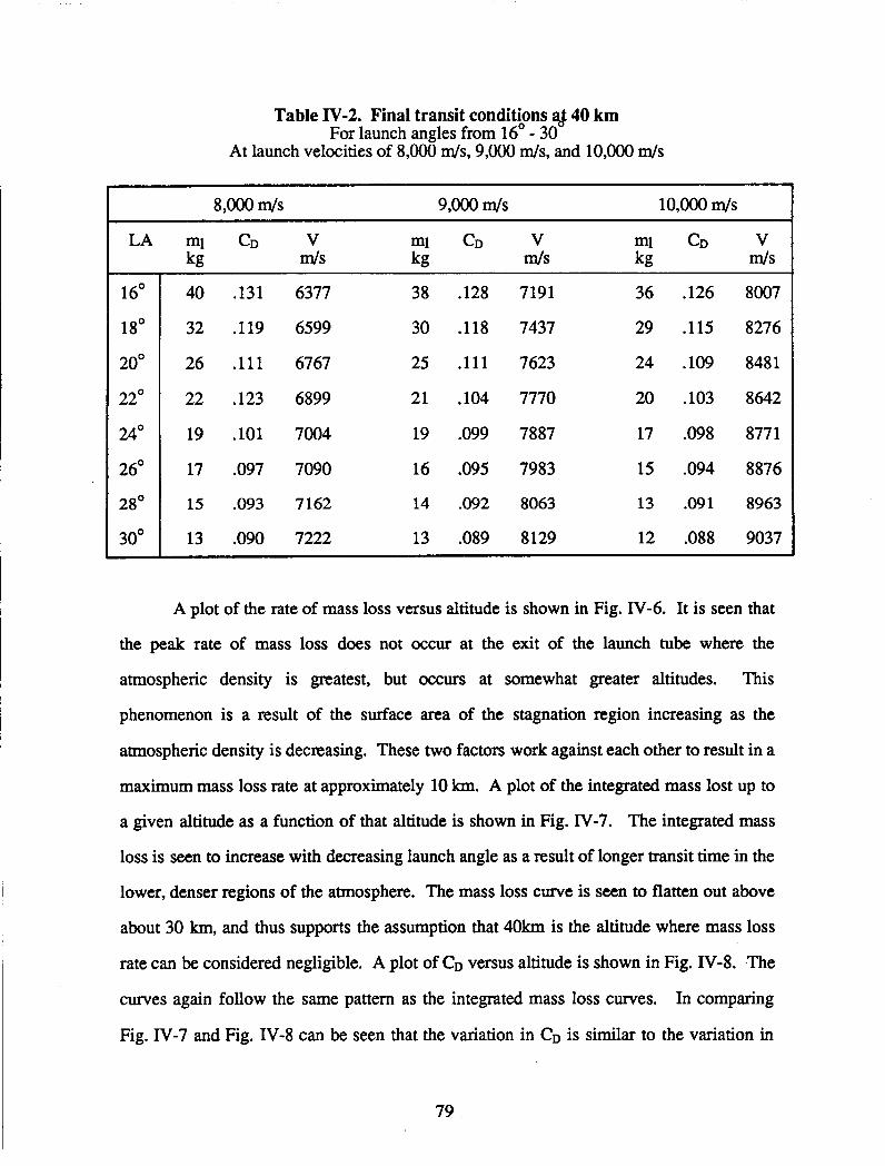
Table IV-2. Final transit conditions q,J 40 km For launch angles from 16' - 30
At launch velocities of 8,000 m/s, 9,000 d s , and 10,OOO m/s
16"
18'
20'
22'
24'
26'
28'
30'
40 .131
32 .119
26 .111
22 .123
19 .lo1
17 .097
15 .093
13 .090
6377
6599
6767
6899
7004
7090
7162
7222
38
30
25
21
19
16
14
13
.128
.118
.111
,104
.099
.095
.092
.089
7191
7437
7623
7770
7887
7983
8063
8129
36 .126 8007
29 .115 8276
24 ,109 8481
20 .lo3 8642
17 .098 8771
15 .094 8876
13 .091 8963
12 .088 9037
A plot of the rate of mass loss versus altitude is shown in Fig. IV-6. It is seen that
the peak rate of mass loss does not occur at the exit of the launch tube where the
atmospheric density is greatest, but occurs at somewhat greater altitudes. This
phenomenon is a result of the surface area of the stagnation region increasing as the
atmospheric density is decreasing. These two factors work against each other to result in a
maximum mass loss rate at approximately 10 km. A plot of the integrated mass lost up to
a given altitude as a function of that altitude is shown in Fig. IV-7. The integrated mass
loss is seen to increase with decreasing launch angle as a result of longer transit time in the
lower, denser regions of the atmosphere. The mass loss curve is seen to flatten out above
about 30 km, and thus supports the assumption that 40km is the altitude where mass loss
rate can be considered negligible. A plot of CD versus altitude is shown in Fig. IV-8. The
curves again follow the same pattern as the integrated mass loss curves. In comparing
Fig. IV-7 and Fig. IV-8 can be seen that the variation in CD is similar to the variation in
79

mass loss. This phenomenon is due to the direct relation between body shape and the drag
coefficient. Thus, as the body shape changes due to ablation, the CD changes similarly. A
plot of V/Vo versus altitude is shown in Fig. IV-9. This figure shows that the change in
velocity is very small at altitudes above 40 km., thus again verifying the assumption that
atmospheric effects at altitudes above 40 km need not be considered. In a plot of final
V/Vo versus launch angle (Fig. IV-lo), velocity losses, as expected, are seen to decrease
with increasing launch angles. Figure IV-10 is shown for all three initial launch velocities,
and all the curves are very similar, showing that the fractional velocity loss is
approximately the same for all launch conditions.
Obviously, as the launch angle is increased, the aerodynamic heating is reduced,
the ablative losses decrease, the CD remains smaller, and the final velocity is increased.
For the system considered, there are many conflicting design considerations. Lower
launch angles achieve a more energy-efficient means of orbital transfer, but in turn result
in higher mass and velocity losses. Conversely, keeping the launch angle high to minimize
mass and velocity losses results in excessive amounts of on board propellant required to
achieve the desired orbit. Strictly examining the atmospheric transit characteristics, the
different initial launch velocities do not significantly affect the final conditions; however,
chapter V will show that the effect of launch velocity on the orbital mechanics is
substantial.
Realizing that there are conflicting design constraints for the complete ram
accelerator system makes an optimization of any single aspect impossible. Thus,
examining only atmospheric transit characteristics, a maximum launch angle is desired to
achieve a minimal mass and velocity loss. The smaller ablative mass loss is desirable in
order to reduce the overall structural mass of the vehicle to allow for a larger payload
fraction.
80

STABILITY AND CONTROL
To examine the problem of stability and control, the vehicle geometry and mass
distribution must be defined. For the ram accelerator mass launch concept the current
vehicle has a length of 7.5 m, diameter of 0.76 m and a nose half angle of 7". The center
of gravity, CG, for such a vehicle is found to be at 5.3 m from the vehicle nose tip. The
result was obtained from the structural design of the vehicle (see Chapter VII). The center
of pressure, CP, is at 33% of the body length or 2.4 m from the nose tip. Due to the fact
that the CP is located in front of the CG the vehicle is inherently unstable. The effects and
magnitudes of the instability can be estimated by examining small perturbation effects on a
simple dynamic model of the vehicle.
The Eq. of the vehicle's motion is found by summing the moments acting about the
CG of the vehicle using, .
.. Z M ~ ~ = O = I . O - X - F (21)
where x is the moment arm of the applied force, (Fig. IV-11). The moment of inertia, I,
for the vehicle is 6350 kg-m2. To find the resultant angular acceleration, the magnitude of
the applied force must be examined.
For a slender body of revolution the lift coefficient, CL, and the lift-induced drag
coefficient, CDi are approximated as
CL = 24 (22)
CDi = 22 (23)
where i is the incidence angle of the body, (Fig. IV-11).[14] These coefficients are based
on the frontal area of the vehicle. The magnitude of the applied force is
F = 2+qA.cos(i) + i2-qA.sin3(i) (24)
where q is the dynamic pressure and A is the cross-sectional area of the vehicle. Assuming
a small perturbation (such that, cos(i) = 1 and sin(i) = i), the force can be approximated by
81

For small i, the second tern on the right is much smaller than the first term and can be
neglected.
The dynamic pressure on the vehicle varies by three orders of magnitude from an
altitude of 4 km to 40 km, and a 1' incidence angle. Thus, the altitude is the dominant
factor in the magnitude of the vehicles' dynamic response to perturbations. At an altitude
of 4 km, the angular acceleration is approximately 164 rad/secz , while at 40 km, the
angular acceleration is about .16 rdsecz.
In order to counter the angular accelerations, an active stability augmentation is
necessary. It is suggested that a ring of control surfaces mounted on the vehicle as far aft
as possible would provide one possible solution. Assuming control surfaces of 0.1 m2 area
located 6.4 m from nose cone tip, the required moment for zero rotation could be achieved
by a 17' deflection of one of these control surfaces.
This stability analysis is at best an order of magnitude study. It is apparent that at
the lower altitudes the instability of the vehicle is severe. A more detailed investigation of
this problem is clearly required, and possible alternative stability augmentation schemes
must be considered.
IN-TUBE HEATING
Propulsive cycles in the launch tube require that the nose cone of the vehicle retain
a constant geometry throughout acceleration in the tube. It is necessary to determine
whether convective in-tube heating results in significant ablation of the vehicle nose before
it exits the launch tube. Such vehicle ablation occurring inside the launch tube would have
a deleterious effect of the propulsive cycles.
To examine the problem of in-tube heating, an analysis similar to that used in
stagnation region for atmospheric transit is used. Equations 9 - 11 are used to calculate the
stagnation region heating and Eqs. 12 and 13 are used to determine the mass loss and
increased nose tip radius due to ablation. Several assumptions and simplifications that
82

facilitate a conservative heating calculation were made. Since forced convective heating
increases with Mach number, the analysis was carried out for the final 2.5 km section of
where the propellant mixture is 8H2 + 02 and the Mach number range is the highest. The
Mach number range varies from 7 to 11 to achieve an exit velocity of 9.0 km/sec, and from
7 to 13 to achieve an exit velocity of 10 Wsec (see chapter III). It is also approximated,
as it was with atmospheric transit, that the entire spherical nose tip region experiences 65%
of the stagnation heating. As a first order approximation, the CFD normal shock code was
used to calculate post shock temperatures for in-tube conditions of 33 atm pressure and a
temperature of 300 K, at the highest in-tube Mach number. Recovery temperatures were
then calculated with Eqs. 7 and 8 using a Fhndtl number of 0.7. The recovery temperature
(calculated with the greatest Mach number value) was assumed to remain constant
throughout the last section of the accelerator tube. All parameters in the Nusselt number
calculation (Eq. 10) were calculated for the in-tube gas mixture also at fill pressure and
temperature.
To account for heating that already occurs up to the last mixture, it is
conservatively assumed that the nose cone has just reached the sublimation temperature of
carbon-carbon, 3850 K, and is taken to be constant thereafter. The thermal conductivity
for use in Eq. 9 was approximated for the in-tube gas using the following relationship[ 101
where N is Avogadro's number, k,, is a reference thermal conductivity[lO] and SO is the
molecular cross sectional collision area. An average Reynolds number is used in Eq. 9 and
the total heat input is calculated using the total elapsed time of transit for the last section of
tube. After the mass loss is calculated using Eq. 12, the new nose tip radius is found using
Eq. 13.
Results from the first order analysis indicate that ablation due to in-tube heating is
minimal. Using an initial nose tip radius of 3 cm, the total ablative mass loss for a launch
velocity of 9 W s e c and 10 W s e c is 0.23 kg and 1.4 kg, respectively, while the
83

corresponding new nose tip radius is 3.6 cm and 5.2 cm respectively. When repeating the
analysis for a nose tip radius of 5 cm, the ablative mass loss for 9 km/sec and 10 km/sec is
0.55 kg and 3.3 kg with a corresponding new radius of 5.5 cm and 7.2 cm, respectively. In
either case it is clear that if an ablative nose cone is utilized for thermal protection during
atmospheric transit, no additional thermal protection will be needed to guard against in-
tube ablation.
IN-TUBE STABILITY
The vehicle is aerodynamically unstable during its acceleration in the launch tube,
for the same reasons that it is inherently unstable during atmospheric transit. Even if the
vehicle were stable any oscillations in response to perturbations in the pressure field would
be unacceptable. Therfore, in order to keep the projectile centered in the tube and to
prevent any rotational oscillations it is proposed to install a set of three equally-spaced
rails in the bore of the tube. These rails would touch only very lightly on the vehicle.
Additional details are provided in Chapter VII.
CONCLUSION
The investigation of the atmospheric transit phase of the ram accelerator mass launch
concept has included a study of an ablative nose cone as a thermal protection system, as
well as an examination of the dynamic stability of the vehicle. Velocity lost in transit due
to aerodynamic drag is also an important parameter which has been considered in order to
determine the orbital characteristics of the vehicle (Chapter ID).
In the ablation study, only convective heat transfer was considered, and the nose
cone was found to ablate predominantly in the stagnation region. Most of the ablation was
found to occur in the lower atmosphere, with a peak mass loss rate encountered at an
84

altitude of = 10 km. The mass loss due to ablation was found to be negligible above an
altitude of 40km.
At an optimum launch angle of approximately 18' for a 10,OOO m/s launch, 20' for a
9,000 m/s launch, and 22' for a 8,OOO m/s launch the vehicle retained approximately 85%
of its initial velocity, and suffers a mass loss of only 22-29 kg to ablation for all initial
launch velocities. These results support the assumption that a carbon-carbon ablative nose
cone is a viable option for the thermal protection of the vehicle.
The vehicle, as suspected, is highly unstable at low altitudes. At the 4 km launch
altitude the angular acceleration of the vehicle was found to be 164 radsec2. At higher
altitudes the magnitude of the instability is less with the angular acceleration, approaching
0.16 radsec2 at 40 km. The possible use of stability augmentation systems was briefly
discussed, and plausible methods of vehicle stabilization given.
In-tube heating was found to cause minimal mass loss and shape change. For a nose
radius of 3 cm at a launch velocity of 9 Wsec, the in-tube mass loss was 0.23 kg and the
nose radius increased to 3.6 cm. For a launch velocity of 10 Wsec , the mass loss was 1.4
kg and the nose radius increased to 5.2 c n
85

REFERENCES
1. Allen, H.J., "The Aerodynamic Heating of Atmosphere Entry Vehicles - A Review", Fundamental Phenomena in Hypersonic Flow: Proceedings of the International Symposium Sponsored by Cornell Aeronautical Laboratories, Cornell University Press, New York, 1966. pp. 5-14.
2. Ghosh, S., "A Study of Transpiration Cooling for Sharp Conical Bodies in Hypersonic Flow," MSC Thesis, Department of Aeronautics and Astronautics, University of Washington, Seattle WA., May 1988.
3. Hertzberg, A., Bruckner, A.P, eds., "The Ram Accelerator Concept: A Method for Direct Launch of Space Cargo to Orbit," Final Report, NASPJUSRA Advanced Space Design Program, University of Washington, Seattle WA., June 1987. pp. 38-52.
4. Roshenow, W.M., Hartnett, J.P., Handbook of Heat Transfer, McGraw Hill Book Company, New York, 1973. sects. 17, 19.
5. Allen, H.J., and Eggers, A.J. Jr., "A Study of the Motion and Aerodynamic Heating of Missiles Entering the Earth's Atmosphere at High Supersonic Speeds", NACA TN4047,1957. .
6. "CHEMIC", a computational fluid dynamic code for solution of normal shock waves. Sandia Laboratories, June 1981.
7. Anderson, J.D. Jr., Introduction to Flight, 2nd ed., McGraw Hill Books Company, New York, 1985. pp 507-516
8. Eberhardt, S., Department of Aeronautics and Astronautics, University of
9. Schreier, S., Compressible Flow, John Wiley and Sons, New York, 1982. pp
Washington, Seattle WA, private communication, February 1988.
406-455.
10. Hansen, F.C., "Approximation for the Thermodynamic and Transport Properties of
Eberhardt, S. "Tangent wedge approximations in Hypersonic flow", AA400 class
High-Temperature Air," NASA Technical Report R-50, 1968.
notes, University of Washington, Fall, 1987. 11.
12. Taylor, G.I. and Maccoll, J.W., "The Conical Shock Wave Formed by a Cone Moving at High Speed", Proceedings of the Royal Society of London, Cambridge University Press, London, 1937. no. 898 vol 159, pp 459-472.
13. Taylor, G.I. and Maccoll, J.W., "Air Pressure on a Cone Moving at High Speeds", Proceedings of the Royal Society of London, Cambridge University Press, London, 1933. Vol. 139, pp 298-311.
14. Liepmann, H.W., Roshko, A., Elements of Gas Dynamics, John Wiley and Sons Inc., New York, 1957. pp. 305-313,348-352. -
86

NOMENCLATURE
A a
c a
CD CDf G CG
CL CP
CP CP F W d t
hl
h
ho I i k k, 1 Le m ml M Mw m n N Nu Pr 9 r R
Area Acceleration Molar fraction of dissociated gas Coefficient of drag Drag coefficient due to skin friction Coefficient of skin friction Center of gravity Coefficient of lift Center of pressure Coefficient of pressure Constant pressure specific heat Force Rate of heat input Enthalpy Local heat transfer coefficient Heat of formation Moment of inertia Incidence angle of vehicle to the freestream Thermal conductivity Reference thermal conductivity Recession length Lewis number Mole fraction of diatomic gas
Mass loss Moment Molecular weight Mass Mole fraction of monatomic gas Avogadro’s number Nusselt number Prandtl number Dynamic pressure Radius Universal gas constant
c -A 87

Re
Rf S SO
T TR t
U
V
V X
Y
a P r
6
c c
P
d
Reynolds number Recovery factor Surface area Molecular cross section collision area Temperature Recovery temperature Time Normal velocity to shock Tangential velocity to shock Velocity Longitudinal body position Altitude
Angle of attack Constant dependent of flow conditions dissociated air Blowing factor Atmospheric density Angular acceleration Nose radius Summation Heat of vaporization of ablator
Subscripts a monatomic c-c Carbon-carbon composite e Final conditions i Initial conditions 1 Local conditions m Diatomic 0 Freestream conditions r S Stagnation region W Conditions at the wall
Conditions referenced at the nose radius
88

& 3 8 m RADIUS IN IT I AL CONDITIONS
20"-30" DEGREE LAUNCH ANGLE 4000 rn ALTITUDE 9000 m/s 2 0 0 0 Kg 7 DEGREE NOSE CONE HALF ANGLE
Fig. IV-1 The Ram Accelerator Vehicle
NON-STAGNATION REGION
STAGN AT1 ON REGION
Fig. IV-2 Ablative Regions on the Ram Accelerator Vehicle
89

DENSITY, MASS, VELOCITY HELD CONSTANT THROUGH ALTITUDE INCREMENT
DRAG=Cd q A ALTITUDE INCREMENT (100 m
/ DRAG>>mg
Fig. IV-3 Ram Accelerator Vehicle Travellng Through Altitude Increment
INITIAL \ .05
FINAL RADIUS
CONE VOLUME ABLATED BY AERO DY NAMlC HEATING
Fig. IV-4 Model for Nosecone Ablation 90

r TANGENT 'ONE
VEHICLE
Fig. IV-5 Method of Tangent Cone Approximation
91

92

\
9 I I I I I I l l
I I I I I I \
OP OE oz O L 0

I I I I I I
\
I I I, I \
E L' L L' 60' LO'

I I I I I 1
I I I I I I
c S6' 6' S8' 8'
O N A
95

6' L8'
0 cv
CD l-
O N A
96

FREE STREAM
VELOCITY INCIDENCE ANGLE CENTER OF PRESSURE
Fig. IV-11 Stability of the Ram Accelerator Vehicle
97


V. ORBITAL MECHANICS
Rob Gohd Dave Reed
Seshu Vaddey LeAnne Woolf
INTRODUCTION
Once the ram accelerator vehicle exits the atmosphere it pursues a ballistic trajectory
which, if left undisturbed, would intersect the earth (see Fig. V-1). Therefore, to place the
vehicle into low earth orbit (LEO) an appropriate circularization maneuver or series of
maneuvers must be carried out. This requires the vehicle to carry an on-board rocket and
sufficient propellant to accomplish the desired mission. Clearly, the mass of the on-board
propulsion system must be kept to a minimum to maximize the payload carrying capacity of
the vehicle.
A number of possible orbital insertion scenarios for the ram accelerator mass launcher
have been proposed [l], including direct circularization at the ballistic apogee and a multi-
step maneuver involving aerobraking. Preliminary investigations have indicated that the
latter offers the potential for lowest on-board propulsion system mass, and is discussed in
detail in this chapter. Figure V-1 illustrates the various phases of the vehicle trajectory for
this orbital scheme.
To increase the flexibility of this launch concept the use of a parking orbit below the
desired final orbit, e.g. a space station orbit, has been proposed. The parking orbit would be
used to "store" the vehicles until they would be needed in the final orbit, at which time an
orbital transfer would be performed. This would allow the continuous launching of vehicles
without having to synchronize the vehicle launch with the orbital position of the space station
in orbit.
Before the vehicle's orbital path can be studied, a launch site must be chosen; The
primary factors to be considered are maximizing the velocity imparted by the earth's rotation
by launching as close to the equator as possible and minimizing the amount of atmosphere to
98

be traversed by choosing a site with a high altitude. In addition, an equatorial launch site is
desirable to permit all vehicles to be inserted into the same orbit regardless of when
launched. This permits a frequent and flexible launch schedule. A launch site matching
these and other criteria is proposed at Mt. Kenya in Kenya. This site offers a launch altitude
of about 4000 m and lies very near the equator. A detailed discussion of the launch site
selection process is presented in Appendix A.
The development of an accurate atmospheric model is presented in this chapter along
with the orbital mechanics involved in the ascent of the vehicle from the earth's atmosphere
to its initial ballistic apogee, through aerobraking, and into a parking orbit. The analysis was
done using launch velocities of 8,9, and 10 W s e c and launch angles from 16-30'. Finally,
the AV requirements for achieving a parking orbit at approximately 450 km with the use of
an aerobraking maneuver is compared to that for reaching a 450 km parking orbit without
aerobraking. A Hohmann transfer is used to reach the final orbit altitude of 500 km.
.
ATMOSPHERIC MODEL
In previous studies carried out on the effects of the atmosphere on orbital maneuvers
performed "near" the earth's surface (e.g., aerobraking) an isothermal exponential density
profile was assumed for the entire atmosphere [ 11. However, the sensitivity of aerobraking
called for a model more closely based on experimental values of density taken from
atmospheric tables [2]. Using various curve-fitting routines, an equation for the density
variation as a function of altitude could be determined. Initial estimates that aerobraking
would probably occur at altitudes in the range of 30 to 100 km were confimed when further
studies indicated that most of the vehicle drag occurs between 30 and 50 km. The best curve
fit from 30-100 km was found to be an exponential
p = 1.3815 e-Y/6880 (1)
For altitudes under 30 km the following correlation was used [3]:
p = 1.225 e-YRl7O
The scale heights of 6880 and 7170 are in m.
99

This combined atmospheric model is illustrated in Fig. V-2a. A comparison between a
standard isothermal atmosphere [ 11 and the empirical atmosphere is provided in Fig. V-2b.
MULTI-STEP METHOD WITH AEROBRAKING
As indicated in Fig. V-1, the vehicle trajectory can be investigated in several phases.
The fmt phase encompasses the vehicle’s atmospheric transit from the muzzle of the ram
accelerator tube to approximately 40 km above the earth’s surface. At the end of
atmospheric transit, the velocity and flight path angle are corrected for the earth’s rotation
[4]. In Phase 2 standard orbital mechanics equations [4,5] are used to find the ballistic
apogee. A velocity change is made at this initial apogee by the use of an on-board
propulsion system. The vehicle then coasts toward the atmosphere and undergoes
aerobraking (Phase 3). In Phase 4 the vehicle coasts to a second, lower, apogee where a burn
is made to place it into a circular parking orbit. A Hohmann transfer from parking orbit to
final, space station, orbit comprises the final maneuver (Phase 5).
Phase 1: AtmosDheric Transit
During atmospheric transit, drag reduces the velocity of the vehicle from the initial
launch velocity as discussed in the preceding chapter. At the upper edge of the atmosphere,
the component of velocity contributed by the earth’s rotation at launch is added to the vehicle
velocity and the flight path angle adjusted [4].
vh2 = (& 0 COS + (vi* COS 0 2 + 2& vi* 0 COS h COS Q0 COS y (3)
(4)
(5 )
Vi2 = Vh2 + (Vi* S h $0)2
($1 = cot-qVh/(v1* sin $0)) The orbital mechanics calculations proceed from these values of V and (0.
Phase 2: Coast to Initial ADOPW
Given the altitude, velocity and flight path angle at the edge of the atmosphere, the
orbit’s radius at apogee is calculated by [4]

The first three factors determine the orbital parameters as th, vehicle enters the
atmosphere. The body dimensions, mass, and CD determine the amount of drag the vehicle
experiences and thus how much velocity is lost during the aerobraking maneuver. The
where
h =rlVl cos $1 (7)
q = (2gR&/rl - V12 (8)
The velocity at apogee is found from [5]
Va = h/ra (9)
In order to demonstrate the general trend of how conditions at this first apogee depend on
conditions at launch, the altitudes and velocities at apogee for launch velocities of 8,9, and
10 km/s and launch angles of 16-30" were calculated using Eqs. (6) and (9). Figures V-3 and
V-4 illustrate the changes in these apogee altitudes and velocities at apogee, respectively, as
functions of the launch conditions. Note that as launch angle increases, velocity at apogee
decreases more slowly than apogee altitude increases. This seems to indicate that apogee
altitude will dominate further orbital maneuvers.
Phase 3: Aerobraking
Because the details of aerobraking are dependent upon the conditions at the initial
ballistic apogee, Phase 3 combines the coast phase to the atmosphere and the aerobraking
into one phase. The two portions are listed as Phases 3a and 3b, respectively. The factors
that affect aerobraking are:
1. the altitude of the initial ballistic apogee,
2. the velocity at apogee,
3. the change in velocity needed at apogee to raise the perigee to the desired altitude,
4. the vehicle dimensions and mass,
5. the drag coefficient of the vehicle,
6. the desired altitude of the parking orbit.
101

altitude of the parking orbit, when combined with the other parameters, determines the
altitude at which aerobraking occurs. The altitude of initial ballistic apogee, the velocity at
that apogee, and the drag coefficient vary with initial launch angle and launch velocity, as
noted earlier, and with launch altitude. As noted earlier a launch altitude of 4000 m was
selected.
A simple model, called the impulsive model, was developed to gain insight into the
mechanics of aerobraking so as to guide a more comprehensive analysis. In this model the
following assumptions are made:
1. Aerobraking occurs over a small angular distance and short time duration; thus it
can be considered as an impulsive AV at perigee.
2. The flight path angle is virtually zero during aerobraking and the velocity vector is
tangent to the earth’s surface.
3. The flight path is defined by orbital parameters alone.
With these assumptions and the initial apogee altitude, an initial estimate of perigee altitude
for aerobraking is made. From [5]
a = (ra + rp)/2 (14)
E = -C1/(2a) (15)
V3 = (2(& + C1/ra))O*’ (16)
The AV at apogee is found by subtracting the initial velocity at apogee from V3. The orbital
parameters for the elliptical path (see Fig. V-5) to aerobraking are then calculated [5].
e = (ra - rp)/(ra + rp)
p = a(l - eZ) (17)
(18)
Although this model assumes an impulsive AV, it is actually based upon the loss of
velocity across incremental steps of true anomaly, v. The velocity loss in each increment is
calculated by
AVj = -1/2 (CD V2 A At p)/m, (19)
where the density is modeled by Eqs. (1) and (2) and
102

At = (Av r)/V (20)
The velocity, V, at the upper edge of the atmosphere before aerobraking begins is given by
V = (p/p)O.5 [-sin v + (e + cos v)QJ (21)
and Q are shown in Fig. V-6. The velocity is updated after every increment in time where
by
V = V - AVj (22)
By summing the change in velocity for each increment across a range of true anomaly
the total velocity decrement, AV,, for aerobraking can be calculated.
AV,= Z AVj (23)
This AVt is then applied at perigee as an impulsive change to yield an orbit with a new
specific mechanical energy. This approach is justified because the kinetic energy lost is
much smaller than the total specific mechanical energy of the orbit. The specific mechanical
energy is used to calculate a new value of a from
a=-1/2 Me (24)
and then the new apogee r6 is found by using the same value for rp as was chosen at the
beginning of aerobraking.
r6 = 2a - rp (25)
If this apogee altitude is not that of the design parking orbit, a new radius of perigee is
chosen and the process repeated until convergence is achieved.
The major contribution of this model to an understanding of the aerobraking process is
in finding the range of true anomaly, v, over which aerobraking is significant. It was found
that the velocity change outside the range of -20' to +20° is negligible. Figure V-7 illustrates
the ratio of the aerobrake AV for each degree of true anomaly to the total AVt calculated
over +20° for the case of a 20' launch angle at a launch velocity of 9 km/s. As can be seen
from the graph, approximately 75% of aerobraking occurs within 25' of perigee and- about
98% occurs within +loo of perigee. This supports the model's assumption of an impulsive
103

change in velocity during aerobraking. For all cases, a v of 20" corresponds to a flight path
altitude of about 100 km.
From the insight gained using the impulsive model, the study proceeded to a model
which took the effects of atmospheric drag on the flight path into account. This more
complex model uses numerical integration of the equations of motion
dZr/dtz - r(de/dt)2 = -g(ro/r)2 - 1/2(cD p VZ A sin$)/m,
r(dWdt2) + 2(dr/dt)(de/dt) = -1/2(cD p VZ A cos$)/m,
(26)
(27)
to determine the change of velocity during aerobraking. Equations (26) and (27) represent
accelerations in the radial and tangential directions, respectively [6]. For nose-first entry CD
depends on the launch angle and the amount of ablation that results from'atmospheric transit
(see chapter IV).
After choosing a AV to be made at initial apogee, ra and V, give the angular
momentum and specific mechanical energy of the orbit [5].
h=raV3 (28)
&=V32/2- Nra (29)
At the upper edge of the atmosphere, as defrned by the impulsive model, the velocity and
flight path angle can be found by [5]
V4 = (2(e + Nr4))Oa5 . (30)
$4 = cos-l(W(r4 V4)) (31)
Based on the initial conditions, V4 and q4, at the start of aerobraking, Eqs. (26) and (27) can
be numerically integrated using a Runge-Kutta 4th order method. The integration proceeds
until the vehicle is back at an altitude of 100 km as it moves away from the earth and
provides the net change in velocity due to aerobraking is found.
Aerobraking Results
Figure V-8 illustrates the perigee altitude reached during aerobraking. The perigee
altitude decreases with increasing launch angle for two reasons: For higher launch angles the
projectile travels through less atmosphere during ascent and thus ablates less. This means
104

the vehicle retains a lower drag coefficient which in turn requires the projectile to dip deeper
into the atmosphere to obtain the appropriate velocity loss during aerobraking. However, the
effects of CD are minimal compared to the second reason. As the launch angle increases the
initial apogee altitude and apogee velocity also increase, leading to higher velocities at the
beginnning of aerobraking. In order to reduce the projectile velocity enough to attain the
desired parking orbit altitude, the vehicle must go deeper into the atmosphere to obtain the
desired velocity loss from aerobraking.
Another parameter of interest is the velocity, and thus kinetic energy, lost during
aerobraking. The dissipation of energy will generally be in the form of aerodynamic heating
of the vehicle. Figure V-9 shows the absolute value of the AV occurring as a result of
aerobraking. As the velocity loss increases, so must the amount of energy to be dissipated.
The length of time over which the velocity loss occurs, however, determines the rate of heat
load to the vehicle. The aerobraking procedure lasts approximately 15-20 minutes, thus
allowing ample time for energy dissipation.
A major problem which has emerged from the study of aerobraking is that the
projectile will crash to earth if the change in velocity at the ballistic apogee is not done
accurately. Variations of as small as 0.1 m/s in the velocity change applied at apogee meant
the difference between whether the projectile crashed into the earth or successfully coasted
toward parking orbit. This is within the limits of most propulsion systems used today,
however the problem of sensitivity will require the vehicle to have an accurate guidance and
control system on board.
Phase 4: Reachin? ParkinP Orbit
Based on the velocity V5 and flight path angle Q5 at the end of the aerobraking
maneuver, r6 can be found using Eq. (10) after replacing VI with V5 and rl with r5 in Eqs.
(1 1) and (12). Similarly, vf, is calculated with Eq. (13). The velocity required to maintain an
object in a circular orbit is [5]
vcs = (P&,>0.5
105

The difference between V6 and VCS is the amount of velocity change needed to finally place
the projectile into a parking orbit.
DISCUSSION OF RESULTS
The goal of the orbital mechanics study was to minimize the propellant AV
requirements, as opposed to the AV due to aerobraking. Provided in Figure V-10 are the
results for the comprehensive model for total propellant AV required to deliver the vehicle to
the space station. This includes the primary burn at the initial ballistic apogee, the
circularization burn into the parking orbit and the Hohmann transfer to the space station
orbit.
As one can see from the graph there is an optimal launch angle corresponding to each
launch velocity considered. The velocity retention of the vehicle as it traverses the
atmosphere is the primary factor in the performance of the orbital maneuvers. Based on
purely orbital considerations, lower launch angles are preferred because the vehicle’s initial
flight path is more circular, which reduces the propellant AV requirements. However, at the
lower launch angles the vehicle travels through more of the atmosphere which results in
greater losses in velocity, which in turn requires a greater propellant AV. At the higher
launch angles the vehicle retains more of its initial velocity but the vehicle’s ‘flight path
becomes more eccentric, which offsets the benefits of the higher velocity retention. Thus, a
compromise or optimal launch angle occurs somewhere between the two extremes. Table V-
1 lists the optimal launch angle for each launch velocity analyzed and provides the
corresponding orbital maneuver performance for each case.
Figure V-10 also indicates, as expected, that higher launch velocities are more
desirable for orbital mechanics purposes. As the launch velocity increases, the optimal
launch angle decreases and so does the corresponding propellant AV requirement. The other
point of interest which can be noted from the graph is that at higher launch velocities the
curves become shallower, thus permitting a wider latitude of acceptable launch angles.
106

Table V- 1. Optimal performance parameters for the orbital maneuvers
Launch Velocity 8 kdsec 9 kdsec 10 M s e c
Optimal launch angle 22' 20' 18'
lSt apogee burn 1149 ds 630 d s 320 ds
Circularization burn (parking orbit) 117 ds 120 ds 123 ds
Transfer from parking to final orbit 43 m/s 30 ds 30 d s
Total AV 1309 ds 780 d s 473 ds
AV( aerobraking) -252 d~ -507 m / ~ -909 m / ~
Perigee altitude 50.2 km 44.4 km 39.6 km
The total velocity change required from the on-board propulsion system is the measure
of how efficient a set of orbital maneuvers is. In order to determine whether or not the
method emphasized in this study is optimal, a brief analysis of other possible scenarios is
necessary. Two other methods were evaluated, direct insertion and a multi-step method
without aerobraking.
For direct insertion into a circular parking orbit from initial ballistic apogee, the
projectile must be fired at a very low launch angle in order to have an apogee altitude at 450
km, as can be seen from Fig. V-1 1. This increases the amount of time the projectile spends
in the atmosphere, reducing the velocity retention leading to the need for additional heat
shielding (see Chapter IV). This reduces the amount of payload that can be carried and thus
increases the cost of launch [ 11.
Another approach is to impart a change in velocity at the initial ballistic apogee to raise
the perigee altitude to the desired parking orbit altitude. A subsequent burn is then made to
circularize the orbit. This approach allows higher launch angles and launch velocities than
does the use of direct insertion at initial apogee and thus its flexibility approaches that of the
multi-step maneuver with aerobraking. Figure V- 12 illustrates the total AV requirements to
107
place the projectile into the space station orbit at an altitude of 500 km given a launch angle
of 16-30', for a launch velocity of 9 Wsec . This AV is the sum of the absolute values of
the velocity change made at initial ballistic apogee and the velocity change made to
circularize the orbit. Also shown on the figure is the total AV requirement to be provided by
the on-board rockets for the multi-step maneuver with aerobraking. It can be seen that the
use of aerobraking significantly reduces the amount of AV needed, and thus the amount of
on-board propellant. At the optimal launch angle of approximately 20' for the 9 W s e c
launch velocity, the method using aerobraking requires about 40% less on-board propellant
(assuming I ~ P = 297) than using the multi-step approach without aerobraking.
CONCLUSIONS
The ram accelerator mass launch system was initially conceived as a means of
economically launching payloads into low earth orbit. A key part of this concept is the
reduction of the on-board propulsion system mass by minimizing the mission's total change
in velocity in order to increase the payload mass ratio. To reach this goal a multi-step
maneuver using aerobraking has been proposed. The study of the aerobraking process was
fmt performed with a simple model to gain an understanding of the parameters involved in
an atmospheric drag maneuver. This model indicated that aerobraking occurs almost
impulsively near the perigee. These results led to the development of a more comprehensive
model based on spacecraft re-entry analysis. Both models gave similar results, supporting
the approaches taken. Results using aerobraking were then compared with two other
methods of inserting the vehicle into the desired parking orbit. The multi-step maneuver
using aerobraking proved to be more efficient than a direct insertion at fwst apogee or a
multi-step process without aerobraking. Based on these findings, it is felt that aerobraking
can be integrated successfully into the ram accelerator mass launch concept. .
108

1.
2.
3.
4.
5.
6.
REFERENCES
Bruckner, A.P., and Hertzberg, A., "Ram Accelerator Direct Launch System for
Space Cargo," IAF Paper 87-211, 38th Congress of the International Astronautical
Federation, Brighton, United Kingdom, October 10-17, 1987.
U.S. Standard Atmomhere, 1976, NOAA, NASA, USAF, Washington, D.C., October
1976.
Vincenti, W.G., and Kruger, C.H., Jr., Introduction to Physical Gas Dvnamics, Robert
E. Krieger Publishing Company, Malabar, FL, 1965..
Ball, K.J., and Osborne, G.F., Space Vehicle Dynamics, Clarendon Press, Oxford,
1967.
Bate, R.R., Mueller, D.D., and White, J.E., Fundamentals of Astrodynamics, Dover
Publications, Inc., New York, 1971.
Allen, H.J., and Eggers, A.J., Jr., "A Study of the Motion and Aerodynamic Heating
of Missiles Entering the Earth's Atmosphere at High Supersonic Speeds," NACA TN
4047, Washington, D.C., October 1957.
109
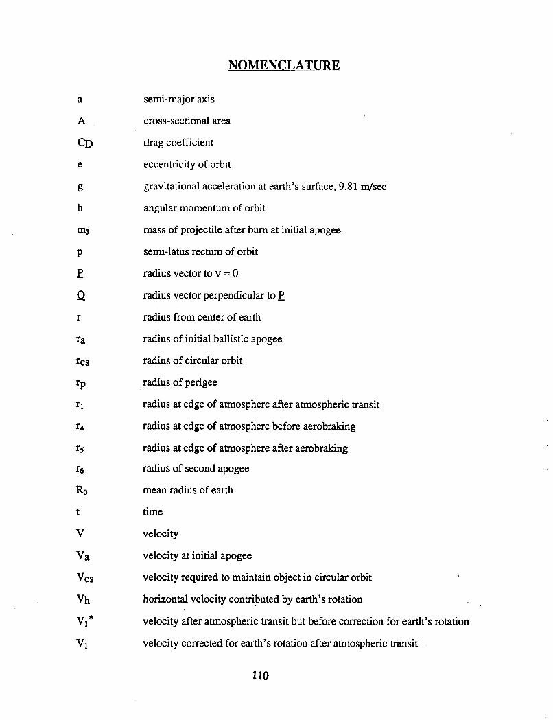
NOMENCLATURE
a
A
CD
e
m3
P
- P
a r
semi-major axis
cross-sectional area
drag coefficient
eccentricity of orbit
gravitational acceleration at earth’s surface, 9.8 1 d s e c
angular momentum of orbit
mass of projectile after burn at initial apogee
semi-latus rectum of orbit
radius vector to v = 0
radius vector perpendicular to
radius from center of earth
radius of initial ballistic apogee
radius of circular orbit
radius of perigee
radius at edge of atmosphere after atmospheric transit
radius at edge of atmosphere before aerobraking
radius at edge of atmosphere after aerobraking
radius of second apogee
mean radius of earth
time
velocity
velocity at initial apogee
velocity required to maintain object in circular orbit
horizontal velocity contributed by earth’s rotation
velocity after atmospheric transit but before correction for earth’s rotation
velocity corrected for earth’s rotation after atmospheric transit
110
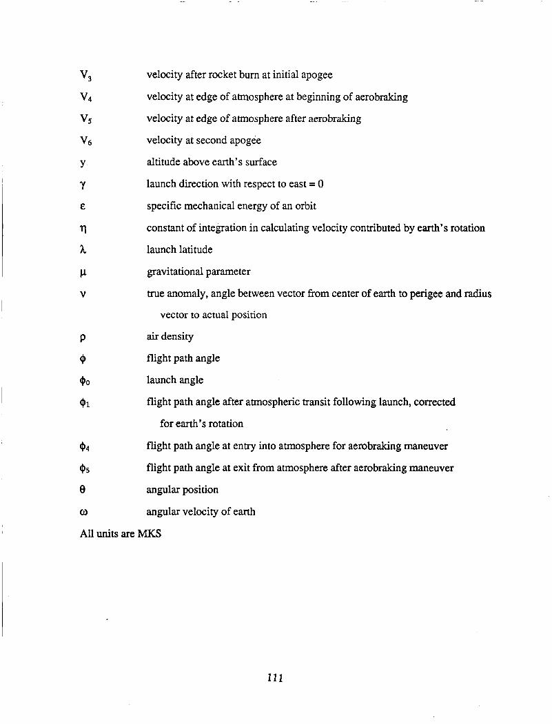
v3
v4
vs v6 velocity at second apogee
Y altitude above earth’s surface
Y E
r\
h launch latitude
P gravitational parameter
V
velocity after rocket bum at initial apogee
velocity at edge of atmosphere at beginning of aerobraking
velocity at edge of atmosphere after aerobraking
launch direction with respect to east = 0
specific mechanical energy of an orbit
constant of integration in calculating velocity contributed by earth’s rotation
true anomaly, angle between vector from center of earth to perigee and radius
vector to actual position
P air density
$ flight path angle
$0 launch angle
$1 flight path angle after atmospheric transit following launch, corrected
for earth’s rotation
$4
$5
e angular position
0 angular velocity of earth
All units are MKS
flight path angle at entry into atmosphere for aerobraking maneuver
flight path angle at exit from atmosphere after aerobraking maneuver
111

PHASE INITIAL APOGEE
FLIGHT PATH WITHOUT AV AT APOGEE
PHASE3a PHASE 2
Fig. V-I Proposed trajectory of the Ram Accelerator vehicle
112

0 20000 40000 60000 80000 100000 IU
Altitude, m
Fig. V-2a Curve fits of density variation of atmosphere with altitude
10-
10- E \ 0, Y
5 10- .- v) c a,
10-
10-
i n-
Isothermal atmosphere
Actual atmosphere
20000 40000 60000 80000 100000
Altitude, m
I V
Fig. V-2b Comparison between actual and isothermal atmospheres 113
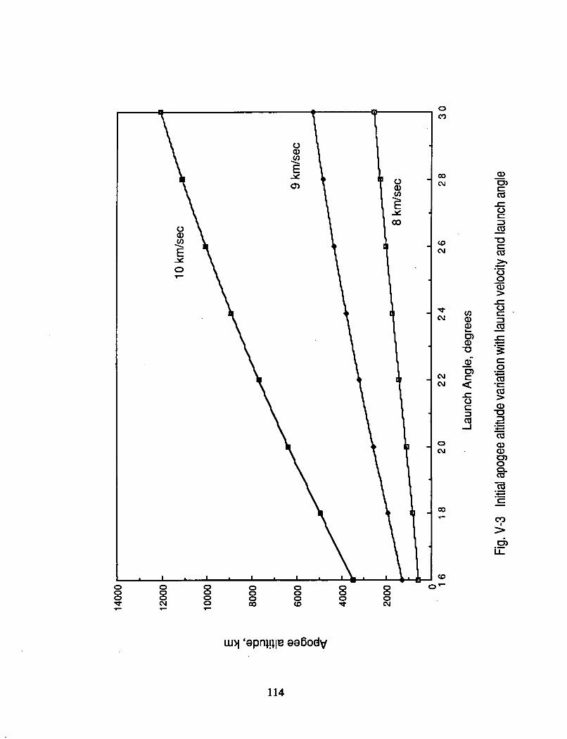

OF 0 0 cu
L
>
115
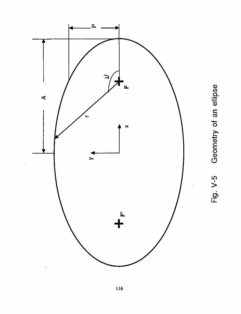
a
X
i t t
m >
116

117
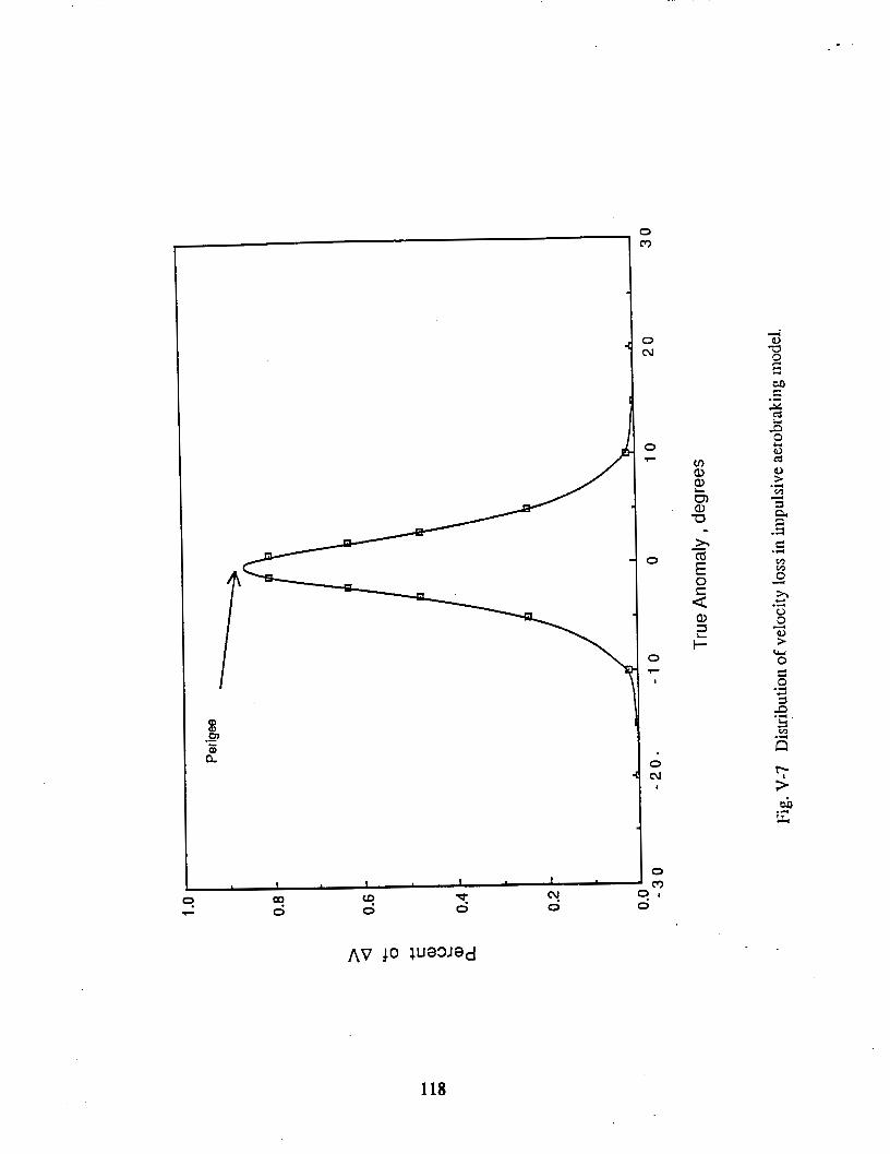
I 1 1
0 m
118

i J
I I
119

\
120

121
Fig. V-I 1 a Apogee altitude extrapolated to lower launch angles
7000
0 %
.- s 9
2
6000 Y
0 0 - a 0
5000 9 km/sec
\ 10 km/sec
4nnn 1 I I I I I .--- 1 2 1 4 1 6 1 8 2 0 2 2 2 4
Launch Angle, degrees
Fig. V-I 1 b Apogee velocity extrapolated to lower launch angles
122

0 0 0 d
0 0 0 m
8 0 cu
0 0 0 7
123


VI. ON-BOARD PROPULSION SYSTEM
Calvin Armerding Michael Aarnio
INTRODUCTION
An on-board propulsion system for the ram accelerator vehicle is needed so that
the vehicle can be maneuvered to a practical parking orbit. Since the vehicle is initially
launched into a ballistic trajectory which intersects the earth, it is necessary to change the
velocity of the vehicle in order to change the trajectory to an elliptical orbit, which can
then be circularized. The basic requirements of the on board rocket system are
established by the orbital mechanics (see Figure V-1 Chapter V). These include the
capability to deliver four separate burns: the initial burn at ballistic apogee, the
circularization burn at the parking orbit, and two burns for the Hohmann transfer from
parking orbit to space station orbit. Another requirement is that the system deliver
sufficient thrust to provide a minimum one-half g acceleration. This is needed to reduce
inaccuracies in the final orbit which are a consequence of finite burn times (the ideal burn
is an impulse, from which no orbital error results). An additional requirement, for
practical reasons, is that the propulsion system be simple and of a proven design. Out of
the broad range of available propulsion options, several meet these criteria and are
worthy of consideration.
The velocity change requirements, the small size of the vehicle, and the desire to
achieve the greatest possible payload fraction necessitates the use of a propulsion method
which offers high specific impulse and low system mass. The vehicle is moving at high
velocity (on the order of 6 km/sec) when passing through first apogee, where the largest
of the velocity changes is required. The Av’s required must be delivered over short time
124

spans, preferably less than two minutes. In an ideal situation the burn would be
instantaneous so that there would be no error due to the changing velocity and attitude of
the vehicle. However, it is impossible to instantaneously change the velocity of a
vehicle, therefore the burn time must be minimized. Decreasing the allowable burn time
increases the required thrust level, and thus the need for a high thrust level becomes as
important as the need for a high specific impulse.
Chemical propellants are generally classified into three principle groups: solid
propellants, liquid propellants, and hybrids. Hybrids are solid fuels with liquid oxidizers
and promise high performance levels; however, they have not been used commercially
and their technology is not sufficiently developed for consideration here.
SOLID PROPELLANTS
Solid propellants are attractive because of their great simplicity. A solid
propellant rocket is a canister filled with a combustible solid. Once ignited, the rocket
burns until the propellant is exhausted. Typical Isp values for solid propellants are less
than 280 seconds, though thrust levels can be quite high due to the rapid combustion.
However, the use of solid propellants in the ram accelerator vehicle introduces a
number of problems. The initial acceleration of the projectile during launch is as high as
lo00 g’s and exerts great stresses on the internal components. Solid propellants range
from brittle to viscoelastic in behavior. A brittle propellant runs the risk of fracture under
the initial loadings, while a propellant that is partially viscous will flow under a lo00 g
acceleration, introducing containment difficulties. In addition, the propellant must be
completely supported during high acceleration periods, as the wall-to-grain bonds are not
capable of supporting such high G loads. This eliminates the possibility of using an aft
mounted propulsion system and requires the use of an end burning grain.
125
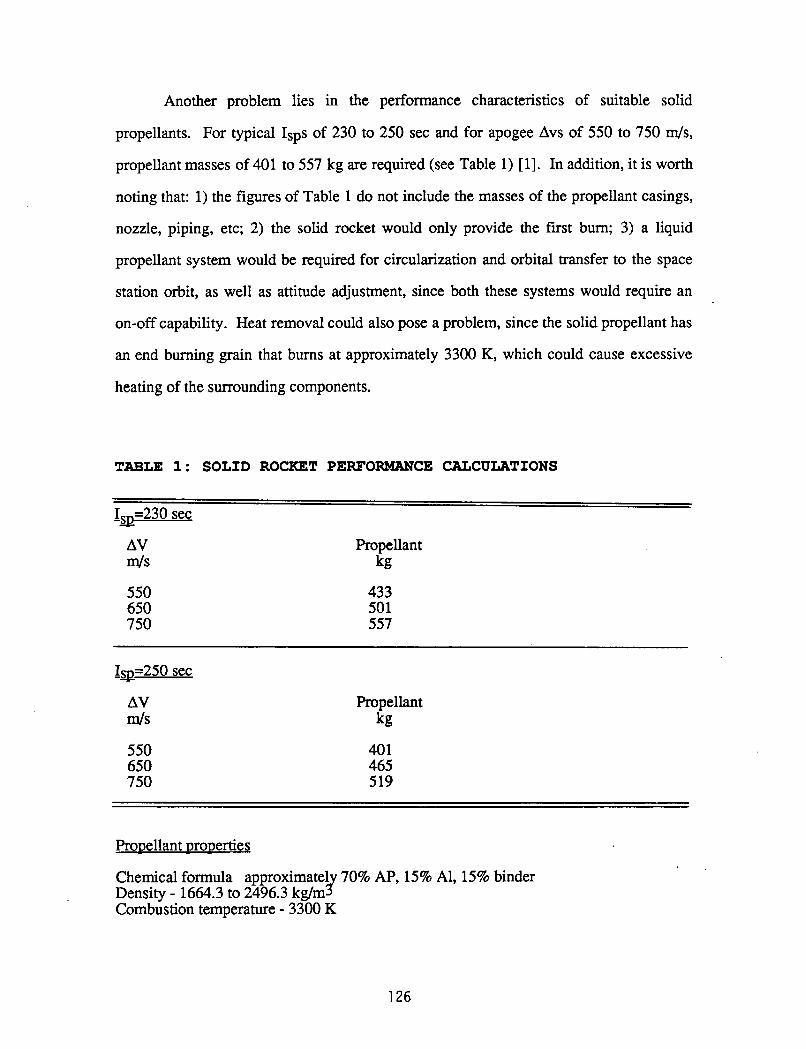
Another problem lies in the performance characteristics of suitable solid
propellants. For typical ISPS of 230 to 250 sec and for apogee Avs of 550 to 750 m/s,
propellant masses of 401 to 557 kg are required (see Table 1) [l]. In addition, it is worth
noting that: 1) the figures of Table 1 do not include the masses of the propellant casings,
nozzle, piping, etc; 2) the solid rocket would only provide the first burn; 3) a liquid
propellant system would be required for circularization and orbital transfer to the space
station orbit, as well as attitude adjustment, since both these systems would require an
on-off capability. Heat removal could also pose a problem, since the solid propellant has
an end burning grain that burns at approximately 3300 K, which could cause excessive
heating of the surrounding components.
TABLE 1: SOLID ROCKET PERFORMANCE CALCULATIONS
-S Is=230 sec
AV d S
550 650 750
Propellant kg
433 501 557
AV m/S
550 650 750
Propellant kg
401 465 519
Propellant properties
Chemical formula approximate1 70% AP, 15% Al, 15% binder
Combustion temperature - 3300 K Density - 1664.3 to 2496.3 kg/m r
126

LIQUID PROPELLANTS
The main restriction on a liquid propellant system is that the propellants must be
storable. This eliminates the highest specific impulse propellants which are all
cryogenic, but it is still possible to obtain reasonably high specific impulses with
available storable propellants. The use of cryogenic propellants requires refrigeration
systems or large amounts of insulation. This would add significant weight and undesired
complexity and cost to the rocket system. Storable propellants can keep the design
simple and can reduce maintenance.
Currently available storable propellants are the fuels hydrazine, N2H4,
monomethylhydrazine, CH3N2H3, known simply as MMH, unsymmetrical
dimethylhydrazine, (CH&NzH2, known as UDMH, ammonia, "3; diethylenetriamine,
(H2NC2H4)2NH, chlorine trifluoride, ClF3; bromine pentafluoride, BrF5; and the oxidizer
nitrogen tetroxide, N204, known as "TO [2]. The decision to use only the most proven
propellants limits this selection to hydrazine, MMH, UDMH, and "TO.
When NTO is used with any of the three hydrazine-based fuels the propellant
combination is hypergolic. With the capability of the propellants to react spontaneously
upon contact with each other, the need for external sources of power to initiate
combustion is eliminated [3]. Hypergolic propellants also provide uniform ignition in the
combustion chamber [2] and combustion instability problems are reduced as a
consequence.
"TO is very dense (1448 kg/m3), which makes it a good choice as an oxidizer
because it will then require minimal storage volume. Other advantages include good
performance, immediate availability, and low cost [2]. The only major disadvantage of
"TO is that it has a relatively high vapor pressure and so its container must be slightly
stronger and heavier than an oxidizer with a lower vapor pressure.
127

Hydrazine provides the best performance of the three fuels [4]. It has the highest
specific impulse and also has the greatest density. Hydrazine also has some very
important disadvantages. When exposed to mechanical shocks hydrazine can violently
decompose at temperatures as low as 360 K [2]. This phenomenon can be reduced by the
addition of large amounts of UDMH. Aerozine-50, a 50-50 mixture of hydrazine and
UDMH, has suitable resistance to shock decomposition but at the cost of a 4% reduction
in specific impulse and a decrease in density to 900.7 kg/m3. In addition to its uses as a
bipropellant, hydrazine may be used as a monopropellant by utilizing iridium as a
catalyst in the decomposition process. This type of a propellant system is very attractive
in its simplicity and is very often used in attitude control thrusters [3,5].
MMH offers performance close to that of hydrazine but is safer for applications
where pressure shocks could occur. The specific impulse of an MMH system is only 2%
lower than that of a hydrazine system. Under a pressure shock, MMH undergoes only a
moderate decomposition and then only at temperatures above 490 K [2]. The density of
this propellant is 874 kg/m3. The performance and characteristics of UDMH are similar
to those of MMH. UDMH offers the same shock insensitivity but at a slightly lower
specific impulse and an even lower density, 786 kg/m3.
With the possibility of pressure shocks, large amounts of hydrazine are
undesirable due to safety considerations. Small amounts of hydrazine are acceptable and
will be required for the attitude control thrusters. The main rocket engine will utilize
MMH and NTO, as this combination offers the best performance of the shock insensitive
propellants. The ratio of oxidizer to fuel is set at 1.75, which results in a ratio of specific
heats, 'y, of 1.25 in the combustion products.
128

MAIN ROCKET MOTOR DESIGN
Theorv
The rocket performance equations are well known, and a simplified presentation
of the formulas used follows. The thrust of a rocket in terms of mass flow, m, and
effective exhaust velocity, C, is
where the effective exhaust velocity is given in terms of the specific impulse, Isp, and
earth’s gravitational constant, go, as
Thrust may also be expressed in terms of throat area, At, thrust coefficient, Cf,
chamber pressure, Pc, and thrust correction factor, cf, as
where Cf depends on y and the pressure ratio such that
The thrust correction factor is used to account for losses arising from nozzle boundary
layers and the use of a nonideal nozzle. For this design it is reasonable to assume a thrust
129
correction factor of 0.96 [6].
The pressure ratio should be as high as possible to attain a large thrust coefficient.
The maximum value of the thrust coefficient, corresponding to a pressure ratio (PJpe) of
infinity when Pa=O, as is the case in orbit, is 2.08 for ~ 1 . 2 5 . In addition to determining
the thrust coefficient, the pressure ratio also sets the area ratio (AdAt).
From Eq’s. 4 and 5 , it is apparent that once the pressure ratio is set, the area ratio and
thrust coefficient become fixed.
Another useful quantity is the characteristic velocity, c‘. It can be expressed as a
function of the effective exhaust velocity and the thrust coefficient. The definition of the
characteristic velocity is [7].
c ‘ = C / C f
where
The characteristic velocity is determined chiefly by propellant properties and partially by
chamber pressure. Once the propellant is selected, the thrust and specific impulse can be
altered by tailoring the pressure ratio.
130
PROPULSION SYSTEM CONFIGURATION
In addition to the main rocket engine, the onboard propulsion system consists of
propellant tanks, valves and tubing, attitude control thrusters, a control package, and a
propellant delivery system. The two types of propellant delivery systems currently in use
are pump fed and pressure fed. For use in the ram accelerator, pump fed systems are
impractical because it is unlikely that the pumps could withstand the high acceleration
loadings to which the vehicle will be subjected at launch. An attractive alternative to
pump systems is found in pressurized propellant delivery systems, which are virtually
insensitive to high accelerations.
.
ProDellant Delivery
The standard method for pressurizing a propellant tank is to use an inert gas, such
as helium, stored in a separate tank. This gas is released into the propellant tanks during
flight by means of an explosive valve (Fig VI-1). The helium flow into the three
propellant tanks is controlled by a pressure regulator, and each tank is isolated by a check
valve which allows the helium to enter the tank but prevents the propellant from
escaping. Once the explosive valve is opened the helium flows into the tanks and forces
the propellants out the other side.
The helium-pressurized system carries an extra tank for storing the helium. The
volume of the helium container is given by [5]
VHe = VP pr /(pi - pf) (8)
The polytropic expansion coefficient, h, which corrects for effects of heat flow to the
helium container, has an approximate value of 1.2 for this application [5]. The regulated
pressure to the system must be higher than the chamber pressure, (the maximum chamber
pressure delivered by a pressure fed system is typically 2.0 MPa or about 20 atm), and
the helium residual pressure should be slightly higher than the regulated pressure. The
13?
regulated pressure was chosen as 2.8 MPa ( 28 am); the final helium pressure as 3.1 MPa
( 31 atm); and the initial helium pressure as 17.2 MPa ( 170 atm). The mass of the
helium container is dependant upon its configuration and the initial pressure.
A relatively new idea in the field of pressurized propellant delivery systems is the
use of a small hydrazine gas generator as an alternative method of pressurizing the tanks
during flight (Fig VI-2). The system is started with a pressure charge which initially
pressurizes the hydrazine tank, forcing some hydrazine across an iridium catalyst
embedded in aluminum oxide. The gas generated by the catalytic decomposition of the
hydrazine is then fed into the propellant tanks to pressurize them. The mass of hydrazine
required to pressurize the tanks is given by [5]
IQ, = Vp P, /. 850,000 (9)
One problem with the gas generator method of pressurization is the heat
generated by the decomposition of the hydrazine. In tests run by Rocket Research
Company this heat was negligible [6], but if long gas generation times occur, heating
could be a considerable problem. Further study of heat generation needs to be
performed.
Another problem is the need to prevent the helium or the hydrazine-generated
gases used to pressurize the tanks from mixing with the liquids in the tanks. This is
prevented by a simple, flexible diaphragm which is initially flush with the tank wall on
the side of the pressurizing gas inlet. As the contents are consumed the diaphragm
traverses the tank pushing propellant ahead of it. Due to the reactivity of rocket
propellants, the diaphragm is most commonly made of stainless steel [5]. This choice of
material requires that tanks be of spherical or quasi-spherical design to reduce the strains
on the diaphragm as it meets comers. The corrosive effects of the propellants also
require that the tanks be made of a material which ksists reaction. Most propellant tanks
132

either the forward or rear tapered section of the projectile without wasting excessive
amounts of volume (See Fig VII-1 in Chapter VI"). Figure VI-3 shows the relationship
have been constructed of titanium, but it is possible to build the tanks of composites with
an inner lining of titanium.
In addition to the check valves discussed above, each tank is equipped with an
isolation valve which keeps the propellants in the tanks until just prior to the initial burn.
This isolation valve is provided as a safety device to prevent leakage of the propellants.
Attitude Control Thrusters
The propulsion system also requires attitude control thrusters. Eight 220 N
thrusters will be sufficient for the vehicle [5 ] . These thrusters use hydrazine as a
monopropellant and are very simple and reliable. They are very light (approximately 1
kg) and small (roughly 20 cm long by 4 cm in diameter) but cost $15,000 to $20,000
each [8]. A good estimate of the amount of hydrazine required to run these thrusters is
5% of the mass of the main propulsion fuel, MMH [4].
A control system is required to activate the main rocket and the attitude control
thrusters at the appropriate moments. A simple timer could activate the main engine
when needed, and accelerometers can measure the Av to a very high degree of accuracy.
Gyroscopes could measure the projectile's attitude, and these measurements could signal
when the attitude thrusters need to be used. Such systems are in common use and are
relatively lightweight and inexpensive.
RESULTS
Main Rocket Motor
Most nozzles built today are contour nozzles, and this type is employed here also.
The exit diameter of the nozzle is taken as 40 cm so that the engine can be placed in
133

between thrust and area ratio at various chamber pressures for a contour nozzle having a
fixed exit area. From this graph it is evident that the highest possible chamber pressure
(2.069 MPa or 20 atm), corresponding to the maximum value attainable with a pressure
feed system, should be used.
Figure VI-4 shows the relationship between specific impulse and area ratio for
several characteristic velocities typical of hydrazine-based propellants. The theoretical
characteristic velocities of the hydrazine based propellants considered in this study range
from 1700 m/s to 1750 m/s [6]. On the other hand, a Rocketdyne publication [9] on real
hydrazine-based rocket motors, similar to the type required for the present vehicle, lists
characteristic velocities between 1530 m/s and 1630 4 s . Based upon the Rocketdyne
information, a characteristic velocity of 1580 m/s is assumed.
The minimum thrust, T, that the main engine must produce is determined from
where Q is the mass after atmospheric transit and a is the desired acceleration. An
acceleration of one-half g, 4.9 d s 2 , results in a minimum thrust of 9710 N. The design
value for thrust is taken as 10,OOO N, which gives a nozzle area ratio of 46.0, a throat
diameter of 5.90 cm, and a specific impulse of 297 sec. Thrusts exceeding 10,OOO N
yield specific impulses which rapidly decrease for the fixed nozzle exit area (see Figs VI-
3 and VI-4).
The nozzle length can be approximated by assuming a conical nozzle with a 150
half-angle. Figure VI-5 shows nozzle length versus area ratio. For an area ratio of 46.0
the length is 63.6 cm. A contour nozzle would be slightly shorter than this. Rockets of a
size similar to this design typically have a nozzle length which is approximately two-
thirds of the total length of the engine [9]. The overall length of the engine is thus
approximately 95 cm. Similarly, the engine mass and thrust are related [9] in such a way
that for 10,OOO N thrust the engine mass is about 60 kg, including the extra mass required
134
to make the engine restartable. Engine cooling was not studied but most engines which
would fit the ram acceleartor application are radiation cooled [9]. The approximate cost
of such an engine is $500,000 to $1,000,000 [8 ] , however, significant cost reductions
may be possible due to the large number of units that will be required for the ram
accelerator mass launch system.
ProDulsion Svstem
The first burn (at the ballistic apogee) is the longest and most critical one, as a
small error in the velocity increment can dangerously affect the aerobraking maneuver.
The burn time is found as follows. The velocity change of the vehicle is the integral of
the acceleration over the burn time
The acceleration is the ratio of thrust, which is constant, to the instantaneous mass.
z Av=Jo T/mdt
However, the mass at any point in time is the mass after atmospheric transit minus the
mass flow rate of propellants multiplied by the time into the burn.
t
0 Av =l T/[Q - A t] dt
The mass flow rate is simply the total amount of propellant burned divided by the total
burn time, assuming a constant mass flow.
Integrating yields,
AV = (T z / mpl) {In[q,I - - mpil)
135

expressed in terrns of Av, pre-burn vehicle mass, mo, and mass of propellant burned,
mp1. A plot of Eq. 16 is shown in Fig VI-6. For example, for Av’s of 500 m/s to 800
m/s (possible first burns) the burn times are 92 to 140 seconds. Not only is the one-half g
acceleration requirement met, but the short burn times indicate the finite bum time errors
will be minimized.
The mass ratio, i.e, the ratio of vehicle mass before burns to vehicle mass after all
burns have been completed, is [7].
M R = e(Av/C) (17)
Using this equation, the total amount of propellant consumed varies from 290 kg to 560
kg for velocity changes of 450 to 990 m/s (Fig VI-7).
Masses of the various valves and other hardware were obtained from the Rocket
Research Company [5] and quantities are tabulated in Tables VI-2 and VI-3. Required
helium and hydrazine masses for the two types of propellant delivery systems are
calculated using Eqs. 8 and 9. An additional 1% must be added to Helium, fuel, and
oxidizer masses as current diaphragm technology is capable of removing only slightly
over 99% of the propellant from the tanks [3]. A summary of these calculations is given
in Tables VI-2 and VI-3. The total mass of the pressurized helium propulsion system is
146.2 kg, excluding the propellant tanks. With propellant and tanks, the mass of this
system is 543.0 kg for a AV of 500 m/s and 740 kg for a AV of 800 m/s. The system
using the gas generator to pressurize the propellant tanks has a total mass of 490 and 670
kg for AVs of 500 and 800 m/sec respectively, including propellant and propellant
storage tanks. This is 50 to 70 kg lighter than the Helium pressurized system, and is an
advantage of the gas generator system.
136
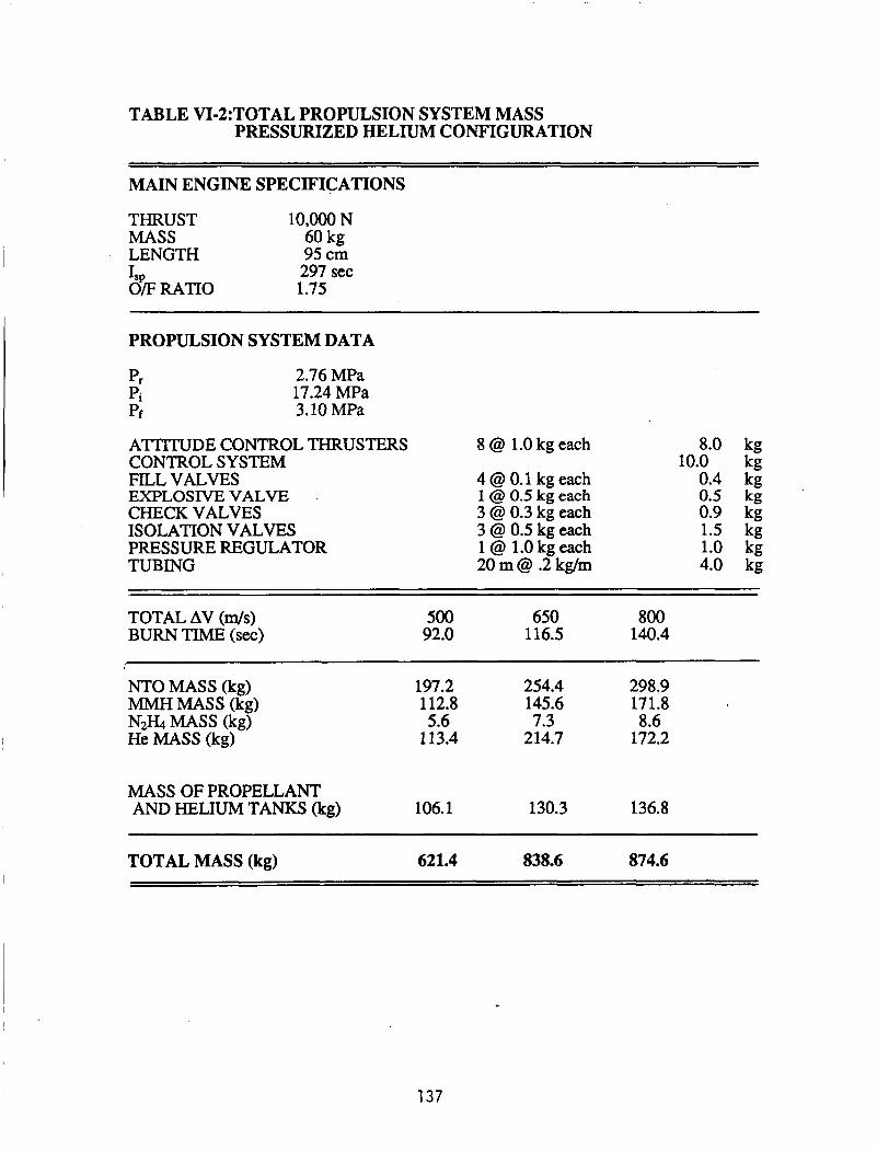
TABLE VI-2:TOTAL PROPULSION SYSTEM MASS PRESSURIZED HELIUM CONFIGURATION
~ MAIN ENGINE SPECIFICATIONS
THRUST 10,OOO N MASS 60 kg LENGTH 95 cm
297 sec kE R A m 1.75
I
I
PROPULSION SYSTEM DATA
2.76 MPa 17.24 MPa 3.10 MPa
ATTITUDE CONTROL THRUSTERS 8 @ 1.0 kg each CONTROL SYSTEM FILL VALVES 4 @ 0.1 kg each EXPLOSIVE VALVE . 1 @ 0.5 kg each CHECK VALVES 3 @ 0.3 kg each ISOLATION VALVES 3 @ 0.5 kg each PRESSURE REGULATOR 1 @ 1.0 kg each TUBING 20 m @ .2 kg/m
8.0 kg 10.0 kg
0.4 kg 0.5 kg 0.9 kg 1.5 kg 1.0 kg 4.0 kg
TOTAL AV ( d s ) BURN TIME (sec)
500 650 800 92.0 116.5 140.4
1
NTO MASS (kg) MMH MASS (kg)
He MASS (kg) N2H4 MASS (kg)
197.2 254.4 298.9 112.8 145.6 171.8 5.6 7.3 8.6
113.4 214.7 172.2
MASS OF PROPELLANT AND HELIUM TANKS (kg) 106.1 130.3 136.8
TOTAL MASS (kg) 621.4 838.6 874.6
137

TABLE VI3:TOTAL PROPULSION SYSTEM MASS GAS GENERATOR CONFIGURATION
MAIN ROCKET SPECIFICATIONS
THRUST 10,000 N MASS 60 kg LENGTH 95 cm
297 sec 1.75 Is,
O F
PROPULSION SYSTEM DATA
ATTITUDE CONTROL THRUSTERS CONTROL SYSTEM FILL VALVES PRESSURE CHARGE CHECK VALVES ISOLATION VALVES GAS GENERATOR TUBING
8 @ 1.0 kg each
3 @ 0.1 kg each 1 @ 0.5 kg each 3 @ 0.3 kg each 4 @ 0.5 kg each 1 @ 0.5 kg each 20 m @ .2 kg/m
8.0 kg 10.0 kg
0.3 kg 0.5 kg 0.9 kg 2.0 kg 0.5 kg 4.0 kg
TOTAL Av ( d s ) BURN TIME (sec)
500 650 800 92.0 116.5 140.4
NTO MASS (kg) MMH MASS (kg) N2H4 MASS (kg)
197.2 254.4 298.9 112.8 145.6 171.8 5.3 6.8 7.1
MASS OF PROPELLANT TANKS (kg) 79.0 93.1 103.9
TOTAL MASS (kg) 480.5 586.1 667.9
138

CONCLUSION
This study has shown that the onboard propulsion system for the ram accelerator
vehicle does not require new technology or present any major technical problems. A
liquid propellant rocket engine using monomethylhydrazine and nitrogen tetroxide
appears to be the most practical choice. Such a system would employ a gas generator
propellant delivery system to reduce system mass. The remaining propulsion system
components are commercially available at reasonable costs. The cost of the main engine
and the attitude control thrusters could approach $1.2 million, which indicates that engine
recovery and re-use is necessary for the ram accelerator to be cost effective. However,
the large number of units required would most likely reduce the costs significantly. The
entire propulsion system mass is approximately 30% of the proposed vehicle launch mass
of 2000 kg, which is very promising. Further studies need to be performed in the area of
heat generation by the main engine and the gas generator system, but preliminary studies
do not indicate a problem.
139

REFERENCES
1.
2.
3.
4.
5.
6.
7.
8.
9.
Micheli, Paul, formerly of Aerojet General, Private Communication, March 1988.
Holzman, R.T., Chemical Rockets, Marcel Dekker, New York, 1969, pp. 171-182.
Landel, R.F., Rembaum, A., Chemistry in Space Research, Publishing Company, Inc., New York, 1972, pp. 267,465-593
American Elsevier
Schmidt, E.W., Hvdrazine and Its Derivatives, John Wiley & Sons, New York, 1984, p. 807.
Schmitz, Bruce, Rocket Research Company, Private Communication, February 1988.
Sutton, G.P., Ross, D.M., Rocket Propulsion Elements, John Wiley & Sons, New York, 1976, pp. 76-78.
Oates, G.C., Aerothermodvnamics of Gas Turbine and Rocket Propulsion, American Institute of Aeronautics and Astronautics, Inc., New York, 1984, pp. 52,61-72.
Peineman, Fred, Rockwell International, Rocketdyne Division, Private Communication, February 1988.
"A Past to Build a Future On", Rockwell International, Rocketdyne Division, Publication 57 1-N-2 NEW 9-84.
140

NOMENCLATURE
a acceleration of vehicle
Ae
C
c f
C'
m,
t
T
T,'
Y Av
z
Cf
nozzle exit area
nozzle throat area
effective exhaust velocity
thrust coefficient
characteristic velocity
gravitational acceleration at Earth's surface
specific impulse
vehicle mass at any point in time
mass flow rate
vehicle mass after ablation
mass of propellant burned during initial burn
mass ratio, total mass to payload mass
combustion chamber pressure
nozzle exit pressure
final Helium pressure
initial Helium pressure
regulated pressure of propulsion system
gas constant
time
thrust
total temperature at the throat
ratio of specific heats
velocity change
burn time
thrust correction factor
141

142

K 0 I- K W a
!i cn 4 t3
a I I 1
143

I I I I I I I I I I I I I I
144

I I I I I I I I I
0 0 w-4
0 03
0 co
0 +
0 nl
0
i i
0
d
.d .& P; d a) 2
Y
8 1
Ei 3 .d

5 3
.H
146

3 8
a
F II >
0 m 0 m 0 02 4 4
0 m cu m 0 * 0 0

\\ i
\ \
\
148
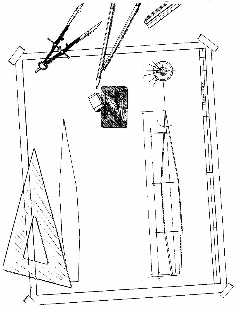

VII. STRUCTURAL DESIGN OF THE PAYLOAD VEHICLE AND LAUNCH TUBE
Carlos Rodriguez Jack Wolda
INTRODUCTION
The overall success of the ram accelerator concept depends ultimately on the
successful design of a payload vehicle. In the design process, it becomes evident that on-
board propulsion, flight mechanics, orbital mechanics and aerobraking, and launch tube
design are all highly sensitive to vehicle mass and geometry.. To optimize the perfomance
of the ram accelerator, the vehicle must meet the following requirements:
The vehicle must withstand a 1,000g acceleration, a maximum pressure of 169 MPa
(25 Ksi), and temperatures of the order of 3,000 OK to 4,200 OK for brief periods (-1 sec).
The total mass is 2,000 kg, and a payload fraction of 50% is desired. This vehicle must
accommodate a rocket and propellants for circularization maneuvers and attitude controls for
stability.
This chapter emphasizes the design of the payload vehicle and presents a simple
approach to launch tube design. In the preliminary analyses, simplified models are used to
determine stress components and, ultimately, shell thicknesses. These results then serve as a
starting point for a finite element analysis. The cargo vehicle is similar to the centerbody of
a conventional ramjet; a fixed launch tube is used as the outer cowling of the ramjet and is
filled with a premixed fuel and oxidizer mixture. A pointdesign outside diameter of 0.76 for
the payload vehicle was chosen as noted earlier in this report.
VEHICLE CONFIGURATION COMPARISON .
This section discusses the effect of the location of various internal components on the
physical and structural properties of the vehicle. The physical properties include mass, total
length, center of gravity, and other geometric characteristics. The structural design criteria
149
address vehicle resistance to axial buckling, resistance to pressure collapse, and overall
structural soundness. Two basic configurations were proposed and examined: 1) the rocket
nozzle is located in the rear with the payload compartment in the front, 2) the rocket is in the
front with the payload compartment aft. These two configurations are shown in Fig. VII-1.
Before addressing the advantages and disadvantages of each configuration, some of the
constraints placed by other than structural considerations are discussed.
One of the requirements for vehicle stability is that the center of gravity be placed as
far forward as possible to minimize the extent of attitude control needed. This suggests that
the payload be placed immediately behind the nose cone ablator (type 1 in Fig. VII-1) since
the mass of the payload is expected to be approximately half of the launch mass. This would
place the rocket motor in the tail of the vehicle, since the rocket nozzle must be located either
in the nose or the tail of the vehicle so that the circularization burn can be performed. This
configuration requires the removal of either part of the nose or part of the tail section so that
the nozzle may be exposed.
One of the disadvantages of locating the rocket motor in the rear is that the blunt
shape of the tail cannot be used in the aero-braking maneuver currently being studied.
However, it was decided that the stability problem is more serious than the aero-braking
inconvenience, and that nose first aerobraking is acceptable. Since no major advantages in
the type 2 configuration could be found, the type 2 configuration was discarded.
The propellant tanks must be arranged in such a way that the center of gravity be as
far forward as possible. If the payload is placed in the front, then the propellant tanks must
be located between For stability
considerations, the three propellant tanks should be arranged such that the densest propellant
is closest to the front. Another approach is to put the Nzo4 tank ahead of the payload
compartment since it is has a density of 1443.7 kg/m3. * This would help move the center of
gravity forward, but there would be increased complexities in propellant tubing and a
the rocket motor and payload (in the middle).
*It was assumed for present purposes that the payload is water.
150

corresponding increase in total launch mass. These complexities were avoided since, as will
be seen later, any unnecessary increase in total launch mass is undesirable.
PRESSURE AND TEMPERATURE DISTRIBUTIONS
The worst case pressure distributions over the vehicle of the ram accelerator were
found for both the thermally choked mode and the oblique detonation mode. These pressure
distributions were obtained from computer simulations of the two in-tube launch modes of
the ram accelerator [l], as discussed in Chapter III. For the thermally choked mode, the
maximum pressure was obtained at a velocity of 1.6 W s e c with O X & + 02. Fig. VII-2
shows the pressure distribution as a function of percent body length. The graph reveals that
the pressure increases from 3 MPa (.4 Ksi) to 12 Mpa (1.74 Ksi) along the cone, and then
stays constant until the point in front of the normal shock. This shock causes the pressure to
jump to 90 MPa (13 Ksi), and the pressure then slowly increases towards the rear of the body
to a value of 94 MPa (14 Ksi).
In the oblique detonation drive, the peak pressure distribution occurs at a velocity of
7.2 W s with a fill mixture of 8H2 + 02 (Fig. VII-3). The pressure along the nose cone and
body is relatively constant at 20 MPa (2.9 Ksi). For this simulation, the frustum that creates
the strong shock wave used to ignite the gas mixture is at 72% body length. Nevertheless,
the optimum location and height of the frustum remains to be determined. Here the pressure
jumps to a maximum of 169 (25 Ksi), decreases to 140 MPa (20 Ksi) at the rear comer, and
then decreases linearly along the rear cone to 17 MPa (2.4 Ksi).
From the same computer simulations, the temperature distribution along the body for
the oblique detonation drive was obtained and is shown in Fig. VII-4. The temperature on
the body before the frustum remains constant at about 360 OK. After the oblique shock, it
jumps to 4,200 OK, and decreases linearly along the rear cone to a value of 2,900 OK. The
temperature effects on the design of the vehicle are discussed in the following section.
151
CHOICE OF MATERIAL
After extensive research as to which material to use for the main frame of the vehicle,
the following two were chosen: graphite/epoxy (T300/5208) and titanium alloy (Ti-8Mo-
8V-2Fe-3Al). The graphite/epoxy's favorable characteristics are its light weight, high
ultimate strength, high modulus, and low production cost compared to other composites.
High-strength T300/5208 (p = 1550 kg/m3) was chosen from the group of graphite/epoxy
composites because it is approximately 50% stronger in transverse and longitudinal
compression than high-modulus or ultrahigh-modulus graphite/epoxy. Titanium, although it
is three times denser than graphite/epoxy, is two and a half times stronger, thus requiring a
thinner body wall and increasing the payload volume. Titanium is also easier to manufacture
and machine although it is more expensive than graphite/epoxy. The general properties of
T300/5208 are compared to those of titanium alloy in Table MI-1.
Composites are directional in nature, and as a result, it is possible to construct the
material so that it will meet specific load requirements without wasting material and weight,
and provide stiffness and strength only where needed. Although allowing the designer to
tailor the material for the specific loading conditions, the anisotropic nature of composites
creates the problem of selecting the proper orientation for the design application. This,
however, does not occur in metal design because metal is isotropic. Therefore, theanalysis
and design for composites must be refined to higher orders to provide a basis for selecting
proper orientation and for defining stresses on the body. Thus, the average properties of a
layup orientation of (Oo/900), were chosen for the isotropic approximation because this gives
the highest strength, considering the biaxial loading conditions imposed on the body [2].
This layup is shown in Fig. VII-5. By convention, the 0' direction is defined in the direction
of the acceleration and the layup is indicated to be symmetric by the subscripted s.
152

TABLE VII-1: COMPARISON OF PROPERTIES OF GRAPHITE/EPOXY AND TITANIUM ALLOY
PROPERTIES GRAPHITE/EPOXY TITANIUM ALLOY (T300/N5208) (Ti-8Mo-8V-2Fe-3AI)
Ultimate Transverse Compression Strength
Ultimate Longitudinal Compression Strength
Longitudinal Compression Modulus
Transverse Compression Modulus
In-Plane Modulus ' (O/H5/90),
Out-of-Plane Modulus (O/H5/90),
Density
Poisson's Ratio
526 MPa (76.3 Ksi)
517 MPa (75 Ksi)
60.9 GPa (9.1 Msi)
60.1 GPa (9.0 Msi)
69.9 GPa (10.1 Msi)
9.65 GPa (1.4 Msi)
1550 kg/m3 (.056 lb/ii3)
0.297
1310 MPa (190 Ksi)
1310 MPa (190 Ksi)
1 13 GPa (16.5 Msi)
113 GPa (16.5 Msi)
N/A
N/A
4844 kg/m3 (. 175 Ib/in3)
0.3
The other options for materials were aluminum, graphite/polyimide composites,
metal matrix composites (graphite/aluminum, graphite/titanium), and ceramic matrix
composites. These were all discarded for reasons of high cost (metal matrix composites,
graphite/polyimide), brittleness (ceramic matrix composites), or comparatively low strength
(aluminum).
The only problems foreseen using T300/5208 or ultra strength titanium alloy are their low
temperature tolerance. The vehicle sees a maximum temperature of 4200 OK, and the
maximum short term temperature, neglecting moisture effects, that T300/5208 can withstand,
is 450 O K . The maximum service temperature for titanium is 922 OK. However, because the
vehicle sees this temperature for approximately one second, it is possible and feasible to
153
wrap the vehicle in a thin ablative shield such as carbodcarbon composite which is a
standard ablative material.
SHELL ANALYSIS
Isotropic ApDroximation
Current analytical solutions to shell structures are not applicable to arbitrary shapes,
load conditions, or anisotropic stiffnesses. Thus, numerical solutions are necessary for better
than first order approximations. However, a first-order approximation for the thickness of
the payload vehicle can be made by assuming isotropic properties, constant pressure
distributions, and a simple geometry. These preliminary thicknesses can then be used in a
finite element analysis to ultimately optimize the vehicle mass.
To begin the frrst order analysis, a thin shell approximation was made using cylinders
with the mechanical properties of the titanium alloy described above. Constant cylinder radii
and thicknesses were also assumed. The analysis was performed for four different sections
as shown in Fig. VII-6. Since part of the nose cone consists of an ablative material for
thermal protection during atmospheric transit, the ablative material is not treated as part of
the load bearing structure. Thus, for structural design purposes, the nose cone 1,mks much
like the truncated tail cone. This truncation simply results in a reduction in length since the
nose cone and tail cone were also assumed to be cylinders for lack of better analytical
solutions with the prescribed loading. The radius of each cone was taken to be its mean
radius. Since the cone half angles are small (7' and 5' for the front cone and tail cone,
respectively), the results should be well within first order accuracy. Thus, the vehicle is
divided into four sections as mentioned earlier, all of which are cylindrical. These assumed
geometries are also shown in Fig. VII-6. To obtain a conservative estimate, the internal
hydrostatic pressure of the liquid payload was assumed negligible. This dictated the
thickriess of a thin cylindrical shell as given by the hoop stress equation,
154
0 2 = = t
Because the resultant thicknesses at the two sections upstream of the frustum required
by the oblique II detonation drive were very thin (on the order of 1 mm), the possibility of
buckling failure was recognized. For a long uniform thin-walled cylindrical shell the critical
thickness is given by
For the two sections downstream of the frustum (sections m and IV in Fig. VII-6), the
thin shell analysis yielded thicknesses greater than one-tenth the radius and rendered the thin
shell approximation invalid. An analysis for thick-walled cylinders was then performed for
the more heavily loaded areas from equations presented by Roark [3]. The simple equations
for thick walled cylinders are as follows:
0 1 = 0
2a2
a2 - bz 0 2 = -q
0 3 = - 9 a*
a2 - bz 2 = q
Again, sections III and Tv were modeled as cylinders of circular cross-section with
constant radii and thicknesses.
Note that none of the equations presented above account for stress interactions. Thus,
the design is made such that the structure can withstand the highest stress at each section.
Section I1 is designed with the buckling criterion and Sections I, m, and IV are designed for
the hoop stress. The thick-wall solutions assume i o longitudinal stress. The longitudinal
155

stress was separately computed by modeling the vehicle as a cylinder with hemispherical
caps rather than using the leading and trailing cones. The terms comprising the longitudinal
stress were due to the external pressure at the aft end, and the acceleration of the vehicle. It
was found that the longitudinal stress is smaller than the hoop stress predicted by Eq. 6.
Thus, only the hoop stress entered into the design of sections III and IV. The thicknesses
were computed in two ways; either to withstand 1.4 times the largest applied stress using the
ultimate strength of the material, or to have the critical buckling thickness using a safety
factor of 1.4.
For purposes of optimizing the design, an alternate analysis was made using high
strength graphite/epoxy (T300/5208). It was expected that having a body made from this
light composite material would save structural mass. Again, a first order analysis was
needed before proceeding to a more rigorous one. This analysis was similar to that used for
the titanium alloy. In other words, the composite material was modeled as having isotropic
properties. These properties were obtained from a flat plate with a (Oo/900) layup. The 90'
fibers were used to withstand the compressive hoop stress, and the 0' fibers to withstand the
longitudinal stress. The assumption of isotropy for a first order analysis is considered a
reasonable preliminary design criterion [2].
Of critical importance are the resulting masses for the different cases studied. These
are listed in Table VII-2.
TABLE VII-2: WALL THICKNESSES AND MASSES OF STRUCTURAL BODY SECTIONS
Material Titanium Alloy GraphiteEpoxy
I n m IV
.008 114 ,020 88
.015 345 .015 113 .
.06 1 84 .140 55
.027 496 .063 343
Total Mass 1039 600
156

The total structural mass (not including ablator, tanks, seals, or stiffeners) of a vehicle made
from titanium alloy (Ti-8Mo-8V-2Fe-3Al), using a 1.4 factor of safety and the ultimate
strength of the alloy is 1039 kg. The structural mass of a vehicle built entirely out of high
strength graphite/epoxy (T300/5208) is 600 kg. Although both cases require structural
masses that are rather high, it is clear that a titanium alloy body is not a viable option because
its mass exceeds 50% of total vehicle mass. A reason that titanium turned out inferior (in
terms of mass) to graphite/epoxy is that the thin shells (sections I and II) had to be designed
using buckling considerations (Eq. 4) rather than collapse pressures (Eq. 3). Although the
titanium could withstand the hoop stresses in the front of the vehicle very easily, the
longitudinal stress would cause buckling of the cylinder if the design were made on the basis
of the hoop stress only. Therefore, these shells are thicker than they need to be to withstand
the radial pressure field.
Since the mass of each section is consistently larger for the titanium alloy, any
combination of the two materials would yield a greater mass than a body made entirely of
graphite/epoxy. It is important to note that since a graphite/epoxy body resulted in greater
thicknesses, though lower mass, the internal volume was reduced. To keep the payload
volume a constant, it was necessary to increase the length of the vehicle from 7.15 m for the
titanium vehicle to 7.5 m for the graphite/epoxy vehicle. However, as stated earlier, this still
resulted in the lowest mass.
In previous work, it had been reported that a structural mass as low as 185 kg could
be achieved [4]. However, this mass was achieved by assuming an incorrect pressure
distribution. The mass reported here results from the design of a vehicle that can realistically
withstand the highest pressures at any propulsion mode, along with the 1OOOg’s peak
acceleration.
It is feasible to secure a solid disk onto the end of the payload compartment not only
to act .as the rear end of the payload vessel, but also as a stiffener to enable the vehicle to
withstand the radial pressure. This configuration is not treated in this analysis.
157
Anisotropic Analysis
In order to optimize the structural design, a finite element analysis is required. In
particular, an anisotropic finite element analysis can give high order approximations for the
graphite/epoxy vehicle and pinpoint stress concentrations. These stresses can be controlled
by varying the vehicle thickness until a nominal and more uniform stress distribution exists
over the entire body. In the following analysis, the preliminary thicknesses obtained from
the isotropic approximation for the graphite/epoxy are used in an anisotropic finite element
analysis to obtain displacements, stress distributions, total mass, and moments of inertia.
The code used is SUPERSAP [5]. Because it cannot do fully anisotropic materials, a
quasi-isotropic layup was used. Thus, an optimal layup cannot be determined from this code.
The quasi-isotropic layup is shown in Fig. VII-7. This layup has the simplicity of equal
properties in three directions: along the fibers, perpendicular to the fibers (in the plane of a
flat plate), and through the thickness (perpendicular to the plate). The stiffness matrix can be
described by three independent parameters as opposed to four. This minimizes computing
time and necessary memory.
A total of 804 nodes resulted in 621 four-node two dimensional elements. Four-node
elements were selected because the thickness after the frustum does not allow using shell
elements. Nevertheless, only the profile of the vehicle needed to be specified with a flag to
indicate an axisymmetric structure. This profile is shown in Fig. VII-8. The boundary
condition at the base of the body constrains one surface node from motion in the longitudinal
direction. This has the effect of making the vehicle appear slightly stiffer than it really is in
the region close to the base.
A loading of 1,OOO g’s and the pressure described earlier produced the deformed
configuration in Fig. VII-9 in which the displacement has been magnified 10 times.
Displacements are on the order of 1 cm which is a strain of less than 0.3%. The maximum
displacement was 1.25 cm at the leading edge of the vehicle, but since there is actually an
ablator that precedes it, the displacement is expected to be less. Through inspection of the
158

computer output, it was evident that the hoop stress was the maximum stress present. Figure
VII-10 shows the stress distribution on a distorted body to enhance the detail. The stresses in
this mesh (slightly adjusted from the previous preliminary sizing to avoid stress
concentrations) resulted in stresses that are smaller than the ultimate compression strength of
the GraphiteEpoxy (526 MPa). However, some of these stresses do not meet the 1.4 safety
factor. This indicates that slight resizing of the vehicle thickness should be made to lower
the maximum stresses and to somewhat increase the minimum stress magnitudes to obtain a
more uniform stress distribution, or, alternately, to analyze a ply layup with more fibers in
the 90' direction. The mesh presented here resulted in a structural mass of 625 kg which is
comparable to the mass from preliminary sizing (600 kg). The center of gravity along the
longitudinal axis was found to be 5.3 m Erom the base with a moment of inertia of 702 kg*m2
for the structure or approximately 2270 kg*m2 for the 2000 kg system when the mass is
homogeneously distributed in the vehicle compartments as described above. The center of
gravity is aft of the center of pressure which makes the vehicle inherently unstable.
Although stability problems have previously been recognized, no stability control systems
have yet been designed. Thus, no internal volume has been allowed for them and they are
not part of the total integral mass of the vehicle system at this time.
FAILURE CRITERIA
Note that the thicknesses of the vehicle shell were found for values that avoided
stresses on the body greater than 1.4 the ultimate strength. This simplified criterion for
isotropic materials with simple loadings resulted in thicknesses that were computed for
buckling or for collapse loads, whichever was greater. However, the mechanisms of failure
in composite materials are many and involve interlaminar shear, delamination, buckling,
voids, broken chains, thermal expansion, differential elastic properties, etc [6]. It is noted by
Chamis that the definition of ply failure is still controversial. Thus, failure criteria provide
the basis for establishing the strength of a structure under combined stresses. The existing
failure criteria are many and range from the simple (maximum stress or maximum strain with
159
no stress interaction) to those of greater complexity (three dimensional Huber-Mises yield
criterion) [7]. It is argued by some that to fully take advantage of composite materials, a
design for the full stress-strain range including the range of considerable nonlinearity be
considered [6].
ABLATIVE SHIELD AT VEHICLE REAR
The shock wave of the oblique detonation propulsion mode increases the flow temperature to
a magnitude that would melt the titanium alloy or graphite/epoxy in sections IIl and IV of the
body which consist of a small cylinder and a tail cone as was shown in Fig. VII-6. To avoid
melting or sublimation of the structures, an ablative heat shield is necessary. A standard
carbon/carbon composite ablator was chosen to protect the vehicle. The mass flow rate per
unit area (&/A) of the carbon/carbon ablator being evaporated off and total time, t, for the
vehicle to travel through the launch tube are calculated to determine the necessary thickness
of the ablator. In the oblique detonation mode, the ram accelerator vehicle goes through four
different gas mixtures at different velocities, therefore the mass flow rate per unit area and
time must be determined for each section. The mass flow rate per unit area, (&/A), can be
found from:
q" = AH(&/A) (7)
where AH is the heat of vaporization (2.28 X lo7 J/kg) for carbon/carbon, and q" is
the heat flux from the surroundings to the ablator. Hertzberg and colleagues [lo] have
shown that the wall heat flux is very small below 5 W s e c and varies from 3 x lo5 W/m2 at
5 W s e c to about 2 x 10⁶ W/m2 at 9 W s e c in the propellant mixtures. For present
purposes an average heat flux of 1.2 x 10⁶ W/m2 was assumed. The flight time of the
vehicle between the above velocity limits is approximately 1 second and thus the total heat
load is 1.2 x 10⁶ J/m2. Knowing the total surface area of the cylinder and the frustum, the
mass and thickness of the carbon/carbon ablator were determined as 2.1 kg and 3 mm.
160

PROPELLANT TANK DESIGN
A preliminary design (Fig. VII-1, vehicle type 1) has the tanks placed on top of each
other with the exception of the N2€& (hydrazine) for the attitude control rockets. This tank,
because of its small volume is kept in a spherical or toroidal shell. The tanks are basically
cylindrical in shape, however the comers are rounded to accommodate a diaphragm to push
the propellant out. This configuration appears to provide the most efficient use of space,
with a total volume of 0.245 cubic meters (for a AV of 780 dsec). First approximate
calculations show that a titanium vessel of seven millimeters thick is all that is required to
safely contain each of the propellants during maximum in-tube acceleration.
CENTER OF MASS AND MOMENT OF INERTIA
For simplicity of calculation, the axisymmetric vehicle was divided into four sections.
Each section was assumed to be a solid homogeneous body with dimensions defined by Fig.
VII-6. With this assumption, the sectional mass center x and radial moment of inertia I,,'
with respect to the sectional mass center were calculated for two different structural
configurations. These values are shown in Table VII-3.
TABLE VII-3 : SECTIONAL MASS CENTER AND MOMENT OF INERTIA
I 1.67 2.60 394 88 CARBON I1 2.18 3.691 410 110
COMPOSrrE IrI 0.15 5.23 460 55 Iv 2.20 6.00 1016 346
TITANIUM I 11
3.10 2.33 270 1.38 3.79 176
114 345
rn 0.35 4.93 15 84 IV 2.20 5.92 460 496
161
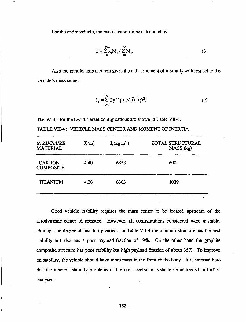
For the entire vehicle, the mass center can be calculated by
Also the parallel axis theorem gives the radial moment of inertia Iy with respect to the
vehicle’s mass center
The results for the two different configurations are shown in Table VII-4.
TABLE VII-4 : VEHICLE MASS CENTER AND MOMENT OF INERTIA
CARBON 4.40 6353 COMPOSITE
600
TITANIUM 4.28 6363 1039
Good vehicle stability requires the mass center to be located upstream of the
aerodynamic center of pressure. However, all configurations considered were unstable,
although the degree of instability varied. In Table VII-4 the titanium structure has the best
stability but also has a poor payload fraction of 19%. On the other hand the graphite
composite structure has poor stability but high payload fraction of about 35%. To improve
on stability, the vehicle should have more mass in the front of the body. It is stressed here
that the inherent stability problems of the ram accelerator vehicle be addressed in further
analyses.
162

RECYCLING THE VEHICLE MATERIAL
Once the payload has been successfully delivered to the space station, there is a
question concerning the reusability of the vehicle’s material. The most common and needed
material for use in erectable space structures and beam building machines has been cited to
be composites, specifically graphite/epoxy [2]. Thus, it would be practical to reuse the
composite material of the vehicle for use in a large space structure such as a space antenna.
According to Inoue [8], there are a wide range of techniques for machining composite
materials with applications to future use in other structures. Thermally set polymer mamx
composites (PMC’s), of which graphite/epoxy is a member, can be cut several ways: 1)
water jet, 2) abrasive water jet, 3) laser beam, 4) electron beam, and 5 ) plasma arc. Options
3-5 are quite costly, but options 1 and 2 are impractical. The scarcity of water in space
necessitates its conservation, so the water used to cut the composite would have to be
recycled. Laser beams however, give the cleanest cuts and incur the least amount of fiber
damage to the material.
Since the rocket motor is expected to cost in excess of one million dollars, it is vital
to retrieve it. Because the payload will be retrieved, the rocket motor is also accessible for
reuse. Details of this procedure have yet to be investigated.
LAUNCH TUBE
The wall thickness for the launch tube wall was determined for AIS1 4340 steel
(assuming a conservative yield stress of 1.4 GPa) with a safety factor of 3 to assure resistance
to fatigue failure and to keep internal deformations small. For thick-walled tube theory, the
following equations apply:
When an internal pressure is applied at the tube inner radius, the radial stress, 03, is
calculated from,
P(K2 - k2)
kZ(K2 - 1) O3 =
163

where K is the ratio of the tube outer radius and the inner radius, and k is the ratio of the
inside radius of the deformed tube to the inner radius of the undeformed tube. Since yielding
of the material is undesirable, k was taken to equal unity to assure tube longevity since a
vehicle may be launched as often as every two or three hours.
Similarly, the tangential stress is calculated from,
P(K2 + k2) 0, =
k2(K2 - 1)
The stress in the longitudinal direction of the tube is given by,
P
K2- 1 q=-. (12)
Lastly, the octahedral equilibrium stress which is a function of the radial, tensile, and
longitudinal stresses is obtained from,
Oes = P [ (a3 - 02)2 + (02 - 01)2 + (ol - 03)2 1421.5 (13)
The equation of interest (the non-dimensional octahedral stress) can finally be used to
determine the thickness,
The wall thickness required for the subsonic combustion portion of the barrel (1 .O m
I.D.) is 12.7 cm while the wall thickness of the oblique detonation portion is 27.6 cm for the
f i t 2.3 km and 24.8 cm for the remaining 2.5 km. This results in a total tube mass of
41,700 metric tons. Together with the initial accelerator, the total system tube mass is
4 1,844 metric tons.
Some alternatives that should be looked into in the future are: Autofretage, multi-
layer construction, smp and wire winding, and composite materials. Manning and Labrow
[9] have developed information on the fust three types. Using one of these alternatives could
greatly decrease the overall weight of the launch tube although it would increase its
164

fabrication complexity and cost. Therefore, the selection of tube wall material is likely to be
guided more by economic considerations than by weight.
As noted in Chapter IV, the vehicle is aerodynamically unstable during the
acceleration in the launch tube. Accordingly, some means of stabilizing the vehicle within
the tube is required. One straightforward approach is to attach a set of three equally spaced
guide rails to the bore of the tube as shown in Fig. VII-11. These rails, fabricated of steel or
other suitable material, would touch the vehicle only very lightly, and thus would not be
expected to wear significantly, or to cause frictional drag or erosion problems for the vehicle.
In order to contain the propellant mixture in the tube, it is necessary to provide end
closures similiar to the petaling diaphragm closure discussed in Chapter II. Also, in order to
seperate the nine different propellant mixtures thin lightweight plastic diaphragms would be
used. These would be sufficiently strong since they would not support a pressure difference
(all propellant mixtures are at a fill pressure of 33 atm.). Clearly, diaphragm and closure
replacement mechanisms will need to be incorporated into the design. This aspect of launch
tube design has not been examined in detail here, but needs to be addressed in future studies.
CONCLUSIONS
In the structural design of a payload vehicle, one configuration was selected. This
configuration placed the orbit circularization rocket in the tail cone with the payload in the
nose cone and midsection. Three propellant tanks were placed in the remaining volume. An
acceleration of 1,OOO g’s and a maximum pressure of 169.8 Mpa (25 Ksi) are the loadings on
the vehicle. The vehicle was designed to withstand the maximum pressure on its surface or
to withstand buckling, whichever is the greater effect. A titanium alloy (Ti-8Mo-8V-2Fe-
3A1) and graphite/epoxy (T300/N5208) composite were considered for the vehicle structural
material. It was shown that the titanium alloy was inferior to graphite/epoxy in terns of
mass. The graphite/epoxy vehicle had a mass of 600 kg for a 7.5 m long vehicle, and the
titanium body resulted in a mass of 1039 kg. A quasi-isotropic finite element analysis was
performed on the graphite/epoxy as a higher order analysis. A high correlation was found in
165

the two analyses but the computer code revealed that the 1.4 safety factor is not met at all the
elements and indicates that slight vehicle resizing is required. With the graphite/epoxy
vehicle a payload mass fraction of 35% was achieved. It is suggested that further studies
emphasize the obtaining of an optimum thickness using a computer code to obtain an
optimum layup and ultimately to minimize the mass. Reusability of the vehicle material for
other space structures is also proposed. Because the rear portion of the vehicle encountered
temperatures of the order of 4,000 OK, an ablative shield over the rear is required to protect
the vehicle. This shield has a mass of 2.1 kg yielding a thickness of 3 mm.. Preliminary
design of the launch tube resulted in a mass of 41,844 metric tons.
166
REFERENCES
1.
2..
3.
4
5.
6.
7.
8.
9.
10.
Bogdanoff, D.W. and Bracket, D., "A Computational Fluid Dynamics Code for the Investigation of Ramjet-in-Tube Concepts," AIAA Paper 87- 1978, AIAA/S AWASMWASEE, 23rd Joint Propulsion Conference, San Diego, CA, June
Department of Defense, National Aeronautics and Space Administration, Advanced ComDosites Design Guide, Wright-Patterson Air Force Base, OH, 1983.
29-July 2, 1987.
Roark, Raymond J., Formulas for Stress and Strain, McGraw-Hill, New York, 1975.
Bruckner, A.P. and Hertzberg, A., "Ram Accelerator Direct Launch System for Space Cargo," Paper No. IAF-87-211, 38th Congress of the International Astronautical Federation, Brighton, England, October 10-17, 1987.
Algor Interactive Systems Inc., ALGOR SUPERSAP, Finite Element Analysis System, Pittsburgh, PA, 1988.
Broutman, L. J. and Krock, R. H., Comuosite Materials, Vol. 5, Academic Press, New York, 1975.
Hinton, E. and Owen, D. R. J., Finite Element Software for Plates and Shells, Pineridge Press, Swansea, United Kingdom, 1984. pp. 235-396.
Inoue, H., "The Machinability of Composites", University of Washington Mechanical Engineering Department Seminar, Seattle, WA, March 4,1988.
Manning, W. R. D., and Labrow, S., High Pressure Eneineering, CRC Press, Cleveland, Ohio, 1971. pp. 121-130
Hertzberg, A., Bruckner, A.P. and Bogdanoff, D.W., An Exploratory Study of Ram Accelerator PrinciDles, Progress Report No. F08635-84-K-0 143, Aerospace and Energetics Research Program, University of Washington, Seattle, WA, April 15, 1985.
167
NOMENCLATURE
a outside radius
A unit area
b insideradius
E Young’s modulus of elasticity
AH heat of vaporization
Iy m ablator mass flow rate
M MachNumber
vehicle mass moment of inertia about the radial axis
Mi sectional mass
N axial forcehit length
p
q
r local vehicle radius
t wallthickness
external pressure on the vehicle
heat flux per unit area
AV apogeeburn
51
x sectional center of mass
center of mass location along vehicle axis measured from nose cone I)
v Poisson’s ratio
p massdensity
cq longitudinal stress
02 hoopstress
a3 radialstress
z shearstress
168

V Poisson’s ratio
P mass density
0 1 longitudinal stress
0 2 hoop stress
0 3 radial stress
z shear stress
subscripts:
0 0 stagnation property
o w wall property
0 1 nose cone structure
o n water payload and container
(h rocket propellant and containers
(h rocket motor, nozzle and casing
169

W 4 u I W
- a a 0 c
E 9
* v)
ZI I " I z l a
'I m I
Z 0
' C
z W c u, 3- u,
Z 0 u, 4
Q 0
Q 0
0
I Z 0
I
a
a
a a m
a a W A W u u a 1 a a W I c 0 LL u, Z 0 c
a
I
a a a c3 I
LL Z 0 u I- Z W Z 0
.. c
I I
I
a c3 LL I
170

- 8 h
- 8
- 8
- 8
- 0
W 0 : u I 4 a
c 0 I c
W I c
a a v) v) W
e
cv I
a .. I
I
a cj I
I&
(QdW) 3tlnSSgud
171

I I I I I I I I I I I I I I I I '
W 0 : I c a Z 0 c W 0 Y
I
4
0 0 I
Y
m
v x . c c3 I Z c
0 LL
0
a
0 Z m
W
3= 0
c I
z c W a u m U I
a W p.
m m
M I I
I
a c3 LL I
(QdW) 3UnSS3Ud 172
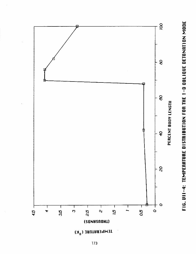
I c L3 Z w 4 s a 0
c Z w u w
eo
a
W 0 0 1 Z 0 c a I
W 0 W 3 0 4
0 0 I
W I + 0 LL
Z 0 c a
I
m
.I
a
I
m a - c v)
0 W
I
a a a c PE W
f W + + a cj
I I
I
I
L
173

0 c
a e e a e e
X
c I
a
F
.. v) I I
I
a . c3 LL I
174

n
a
a I
1 1
I c I
3 W II u I W
I
a a
W 4 W u u a 1
.. rD I I
I
a c j I
LL
175

0 v) *
I
r Z 0 c u W
0 Z 0- - W + W aa a m W W
in
I
a -
uo a u W
u I w
U
I
a
e I 4 u e 0 a c 0 v)
I
v)
. a a
I
I
I
a a a
3 a
U
LL 0
W I
u e 0 u v) 0
0
I
a
5 .. rc I I
I
a . I
LL
176

v)
X
I N
I
a
177

SI"-A
v)
X
I N
I
a
0
II
Z 0 c u LL
c
II
a I
I z L3 a I: c Z
F W u 4 eL u,
0
a
I
d o .. LL m o x
.. QI I I
9
a c3 I
LL
178

I
I
I
2
0 I
I
I
I
w 4 u I W
I
a
O a O a sw .. 0
I c
I - a
. cj. I
LL
179

v) A
U W 0 = c3 W 4 u I W a c3 Z
I
a
I
I
I
3 0 I v)
Z 0 c u Y v)
v) v) 0
u W
3 c
I
a
m
W m a + I u Z a a 4
\
I u
L 0 u c I
5 W I u v)
. a c c I I
I
a G I
k
180

VIII. CONCLUSION
The ram accelerator mass launch system was conceived as a means of economically
launching acceleration insensitive payloads into a low earth orbit. In previous years
feasibility studies were done and proposals made on how to best design the systems of this
concept, This year the research centered on a systems analysis based on the proposals from
previous years. The study was divided into six systems. Each system was researched and
designed based on the use of current technology to launch a 2000 kg vehicle into a low earth
orbit with as high a payload fraction as possible (the goal being 50%).
The vehicle is initially accelerated to a velocity of 0.7 W s e c using a combustion-
driven gas gun. From 0.7 W s e c two ram accelerator propulsive modes are used to propel
the vehicle to the necessary launch velocity. They are a thermally choked subsonic
combustion mode which propels the vehicle to 2.5 W s e c , where a transition is made to an
oblique detonation mode which accelerates the vehicle to 9 Wsec. The total length of the
stationary launch tube is 5.1 km for a maximum acceleration within the tube of lo00 g’s.
The hypersonic launch velocities required the development of a thermal protection
system for the nose cone of the vehicle. A carbon-carbon ablating nose-cone was chosen as
the thermal protection system. At an optimal launch angle of 20°, for a launch velocity of 9
kn~/sec at the equator, the vehicle retains 85% of its original launch velocity and suffers an
ablative mass loss of only 26 kg. The stability of the vehicle is another primary concern
during the atmospheric transit. It was found that the vehicle is highly unstable right out the
end of the launch tube and will require stability augmentation devices such as control
surfaces to maintain dynamic stability.
The prior feasibility studies proposed the use of a multi-step maneuver with
aerobraking to minimize the on-board propellant requirements. A parametric study, was
performed using launch velocities from 8 W s e c to 10 Wsec , and launch angles from 16-
30°. For the multi-step maneuver with aerobraking the optimal launch angles ranged from
c - 3 181

22-18' for launch velocities of 8-10 Wsec , respectively. At these launch angles the
propellant AV requirements range from 1309-473 d s e c to take the vehicle to a space station
in a 500 km orbit. Using an =-N204 bi-propellant rocket with an ISP of 297 sec, the on-
board propulsion system, including propellant and tanks, has a mass of approximately 470-
1000 kg, depending on the launch parameters.
The structural design of the vehicle centered on the use of lightweight, high yield
stress graphite/epoxy composites which could withstand the high pressures and accelerations
the launch tube. A vehicle configuration incorporating T300/5208 graphite/epoxy resulted in
minimal structural mass when approximating the composite material properties as isotropic.
The analysis produced a structural mass of approximately 600 kg for a vehicle length of 7.5
m. Estimates of the vehicle center of gravity place it 3.8 m behind the nose tip with a
moment of inertia of 6,200'kg/m2 about an axis perpendicular to the axis of the vehicle.
At the present stage of the design, the payload fraction of the vehicle is -40% for a
design launch velocity of 9 lcrn/sec. Further refinements of the in-tube propulsion modes and
of the structural design are needed to increase the payload fraction to the desired level of
50% or more. Optimization of parking orbit altitude and/or eccentricity may also provide an
increase in the payload fraction. Methods for recycling vehicle components or for returning
them to earth should be investigated. In addition, a cost analysis of the entire launch system
should be carried out. The work done thus far, however, has demonstrated the potential of
the ram accelerator mass launch concept.
182

APPENDIX A
LAUNCH SITE
LeAnne Woolf
In selecting a site for a mass launch system, the primary factors to be considered
are maximizing the velocity imparted by the earth's rotation by launching from as close
to the equator as possible, minimizing the amount of atmosphere to be traversed by
choosing a site with a high altitude, and selecting a site with minimal seismic and
volcanic activity. In addition, an equatorial launch site is desirable so that the mass
launch vehicles can be placed into the same orbit regardless of when they are launched.
Other issues to be considered include the climate (for minimal environmental stress on .
equipment) and the political stability of the country containing the launch site.
The velocity increment contributed to the projectile's speed by earth's rotation is
determined by the cosine of the latitude in degrees and by the cosine of the launch
direction with respect to due east (see Chapter V) [l]. For a contribution of about 90% or
greater of earth's angular velocity when launching due east, a latitude of less than 30" is
needed. To reduce atmospheric drag losses following launch, the higher the launch
altitude the better. The atmospheric density at 3500 m is approximately 60% of that at
sea level. Furthermore, most of the world's agricultural zones are found below 3500 m
and thus the ram accelerator would not be likely to impinge on the host country's
agrarian pursuits. In order to avoid permanent ice packs that could be quite detrimental
to the ram accelerator installation, an upper limit of 6OOO m altitude was chosen. These
upper and lower limits of latitude and altitude were chosen, after preliminary studies, to
maximize the appropriate parameters while still leaving a wide range of possible launch
sites to be investigated.
The countries with latitudes of less than 30" and mountains of 3500 m or taller are
listed in Table A-1 [2]. Each of them experiences some sort of seismic or volcanic
183
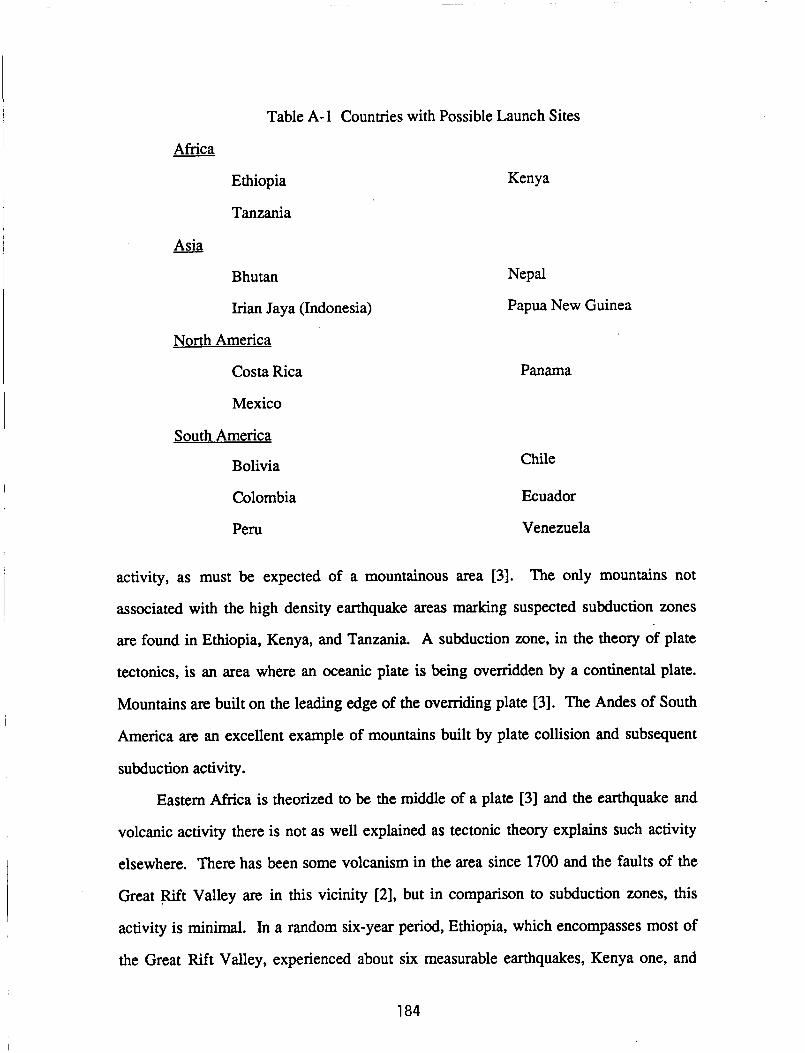
Table A-1 Countries with Possible Launch Sites
Africa
Ethiopia
Tanzania
- Asia
Bhutan
Irian Jaya (Indonesia)
North America
Costa Rica
Mexico
South America
Bolivia
Colombia
Peru
Kenya
Nepal
Papua New Guinea
Panama
Chile
Ecuador
Venezuela
activity, as must be expected of a mountainous area [3]. The only mountains not
associated with the high density earthquake areas marking suspected subduction zones
are found in Ethiopia, Kenya, and Tanzania. A subduction zone, in the theory of plate
tectonics, is an area where an oceanic plate is being ovenidden by a continental plate.
Mountains are built on the leading edge of the overriding plate [3]. The Andes of South
America are an excellent example of mountains built by plate collision and subsequent
subduction activity.
Eastern Africa is theorized to be the middle of a plate [3] and the earthquake and
volcanic activity there is not as well explained as tectonic theory explains such activity
elsewhere. There has been some volcanism in the area since 1700 and the faults of the
Great pift Valley are in this vicinity [2], but in comparison to subduction zones, this
activity is minimal. In a random six-year period, Ethiopia, which encompasses most of
the Great Rift Valley, experienced about six measurable earthquakes, Kenya one, and
184

Tanzania, site of Mt. Kilimanjaro and other volcanic peaks, had about eight measurable
earthquakes [3]. A measurable earthquake starts at a much lower severity than that
which can be felt by most humans. Earthquakes which cause structural damage are even
more severe than those which can be felt. A more thorough seismic study, as well as an
investigation of soil stability, should be made before construction begins; however, a
preliminary site choice is made here.
Several factors work against Ethiopia as a launch site. The flight path of the
projectile is much more likely to pass over the main area of the Asian land mass before
leaving the atmosphere than if launched from Kenya or Tanzania. Ethiopia’s current
government is not particularly friendly to United States interests and the drought and
famine in the country present logistical supply problems. The several rift valley faults
are also a consideration. All mountains of greater than 4000 m height are north of 5”N
latitude while Kenya and Tanzaia offer mountains very close to the equator.
Mt. Kilimanjaro and Mt. Kenya are both very attractive possibilities (see Fig. A-1).
However, Mt. Kilimanjaro has been volcanically active within the last 300 years,
whereas Mt. Kenya has not been active, is not near any major faults, and is nearly on the
equator. Thus, the recommendation of the author is to place the launch site at Mt. Kenya.
Mt. Kenya is about 112 km north of Kenya’s capital city Nairobi and is one of
Kenya’s major tourist attractions. The multiple, rugged peaks are surrounded by fifteen
permanent glaciers [4]. To have less impact on the tourist industry (an important part of
Kenya’s economy [4]) and to avoid the glaciers, the launch tube site should be carefully
chosen. It is also desirable to have a site which allows for a due-east launch. A study of
the contours of the higher slopes of Mt. Kenya has been done and a particular site chosen.
The average slope of this site is about 12’. In order to use higher launch angles, a tunnel
and dike system will need to be constructed, as shown in the example in Fig. A-2. This
construction should not prove to be difficult as tunnels of 9.6 km or longer have been
185.

built since 1882 [6] and the United States is dotted with large, free-standing, cement
structures.
The temperatures around the mountain are in the 10-20°C range all year and the
launch site, at an altitude of approximately 4000 m, is ice free. Annual precipitation is
50-100 cm. The working environment should be quite satisfactory and environmental
stresses on equipment minimal, especially since much of it will be underground.
Mombasa has large port facilities and the country has good aerial and highway systems
[4] capable of handing the logistics of bringing in equipment, supplies, and personnel.
Mt. Kenya seems to be as ideal a launch site as possible and all calculations made in this
report are based on its use as such.
186-

REFERENCES
1. Ball, K.J., and Osbome, G.F., SDace Vehicle Dynamics, Clarendon Press, Oxford,
1967.
The Prentice-Hall American World Atlas, Prentice-Hall, Inc., Englewood Cliffs,
NJ, 1984.
Press, F., and Siever, R., Earth, W.H. Freeman and Company, San Francisco,
1982.
2.
3.
4. Encyclopaedia Britannica, Encyclopaedia Britannica, Inc., H.H. Benton,
Publisher, Chicago, 1975.
"Mt. Kenya," map compiled and drawn by Directorate of Overseas Surveys, 1957.
"World's Longest Railway Tunnels," Railwav Directory and Year Book 1980,
5.
6.
1980.
187

KENYA
TANZANIA
Fig. A-1 Most Likely Launch Sites
188

E
189