design of a vertical tail for the crm configuration e c h n i c a l r e p o r t design of a vertical...
TRANSCRIPT
T E C H N I C A L R E P O R T
Design of a vertical tail for theCRM configuration
Design of a vertical tail for theCRM configuration
Design of a vertical tail for the
CRM configurationDesign of a vertical tail for the
CRM configuration
Design of a vertical tail for the
CRM configuration
Design of a vertical tail for the
CRM configuration
Design of a vertical tail for the
CRM configuration
Design of a vertical tail for the
CRM configuration
Authors : O. Atinault ; D. Hue
APPLIED AERODYNAMICS DEPARTMENT
RT 1/21960 GMT/DAAP - June 2014
UNCLASSIFIED (SANS MENTION DE PROTECTION)

-1-
BP 72 - 29, avenue de la Division Leclerc92322 Châtillon Cedex - FRANCE
Tél. : 01 46 73 40 40 - Fax : 01 46 73 41 41
APPLIED AERODYNAMICS DEPARTMENT
Technical Report N° RT 1/21960 GMT/DAAP
June 2014
Design of a vertical tail for the CRM configuration
Written by :O. AtinaultD. Hue
Verified by :O. Atinault, RT Prévision des performancesG. Carrier, chef d'unité Avions CIvils
Approved by :
Applied Aerodynamics DepartmentJ. Reneaux
UNCLASSIFIED (SANS MENTION DE PROTECTION)

-2-

-3-UNCLASSIFIED (SANS MENTION DE
PROTECTION)
IDENTIFICATION CARD of ONERA REPORT N° RT 1/21960 GMT/DAAP
Issued by :
APPLIED AERODYNAMICS
DEPARTMENT
Contracting Agency :
ONERA
Contract Number :
RGE MM 2013
Programme card number: Date :
June 2014
Title : Design of a vertical tail for the CRM configuration
Author(s) : O. Atinault ; D. Hue
SECURITY CLASSIFICATION : Civil
Title : UNCLASSIFIED (SANS MENTION DE PROTECTION)
ID Card : UNCLASSIFIED (SANS MENTION DE PROTECTION)
Report : UNCLASSIFIED (SANS MENTION DE PROTECTION)
Timing Classification Off
Title : Without object
ID Card : Without object
Report : Without object
Abstract :A vertical tail was designed on the CRM configuration for Onera purpose. This geometry was validated at cruisecondition. It is now released to the scientific community and can be computed or manufactured for other existing orfuture CRM wind tunnel test models.
Key words : CRM; WIND TUNNEL TEST; AERODYNAMIC; DESIGN
BP 72 - 29, avenue de la Division Leclerc92322 Châtillon Cedex - FRANCE
Tél. : 01 46 73 40 40 - Fax : 01 46 73 41 41
-4- UNCLASSIFIED (SANS MENTION DE
PROTECTION)
DISTRIBUTION LIST of ONERA REPORT N°RT 1/21960 GMT/DAAP
Distribution of report
• Outside ONERA :
• Inside ONERA :
DAAP/ACI O. Atinault, D. Hue, G. Carrier (pdf) ............................................................... 2 ex.
GMT A. Cartieri, A. Choffat, F. Ternoy, J.F. Piat, F. Garçon, S. Wolf .................... 6 ex.
ISP Documentation ................................................................................................. 1 ex.
Distribution of identification card
• Outside ONERA :
• Inside ONERA :
DAAP/ G. J.L. Cocquerez ................................................................................................. 1 ex.
DAAP/R.U. B. Mialon, P. Beaumier, P. Duveau ................................................................. 3 ex.
DAAP/GAAP P. Guillen ......................................................................................................... 1 ex.
GMT B. Guillermin ................................................................................................... 1 ex.
Systematic distribution : DSG, DTG, DAI, DCV/2I ................................................................................................ 4 ex.
BP 72 - 29, avenue de la Division Leclerc92322 Châtillon Cedex - FRANCE
Tél. : 01 46 73 40 40 - Fax : 01 46 73 41 41

RT 1/21960 GMT/ DAAP UNCLASSIFIED (SANS MENTION DE
PROTECTION)
-5-
JUNE 2014
GEN-F157-2.
TABLE OF CONTENT
1. INTRODUCTION ............................................................................................................. 6
2. VERTICAL TAIL PLANFORM ..................................................................................... 6
3. VERTICAL TAIL AERODYNAMIC AIRFOIL .......................................................... 7
4. VERTICAL TAIL 3D SHAPE ......................................................................................... 8
5. CFD ANALYSIS ................................................................................................................ 9
6. RELEASE TO THE SCIENTIFIC COMMUNITY .................................................... 11
7. CONCLUSION ................................................................................................................ 11
-6- UNCLASSIFIED
(SANS MENTION DE PROTECTION)
RT1/21960 GMT/DAAP
GMT/DAAP JUNE 2014
GEN-F157-2.
1. INTRODUCTION
ONERA is manufacturing a wind tunnel model of the CRM configuration to be tested in the large transonic wind tunnel facility S1MA in Modane, France. In this context, ONERA needed to add a vertical tail to the CRM model. This short memorandum describes how this vertical tail was designed.
The vertical tail geometry was designed by the Civil Aircraft Unit of the Applied Aerodynamics Department (DAAP/ACI) in cooperation with the Wind Tunnel Division (GMT).
2. VERTICAL TAIL PLANFORM
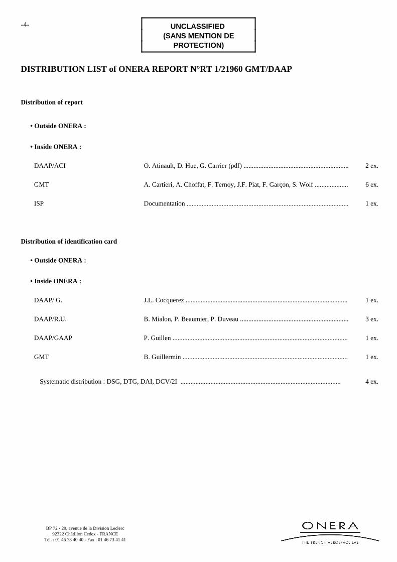
At first, the CRM configuration was compared to existing aircraft in order to find the more similar one.
Figure 1 – CRM mesh superimposed with a Boeing 777-200 sketch (from Internet)
As illustrated in Figure 1, the CRM fuselage perfectly fits with a Boeing 777-200 (note that even the horizontal plane is similar). Consequently, it was decided to design the vertical tail on the basis of the Boeing 777-200 planform.
Figure 2 – Vertical plane planform is sketched on top of the Boeing 777-200 sketch
Figure 2 simply shows the vertical plane 2D planform sketch on top of the Boeing sketch, and Figure 3 zooms in the vertical tail area. Note the small spline curve at the leading edge of the tail.
RT 1/21960 GMT/ DAAP UNCLASSIFIED (SANS MENTION DE
PROTECTION)
-7-
JUNE 2014
GEN-F157-2.
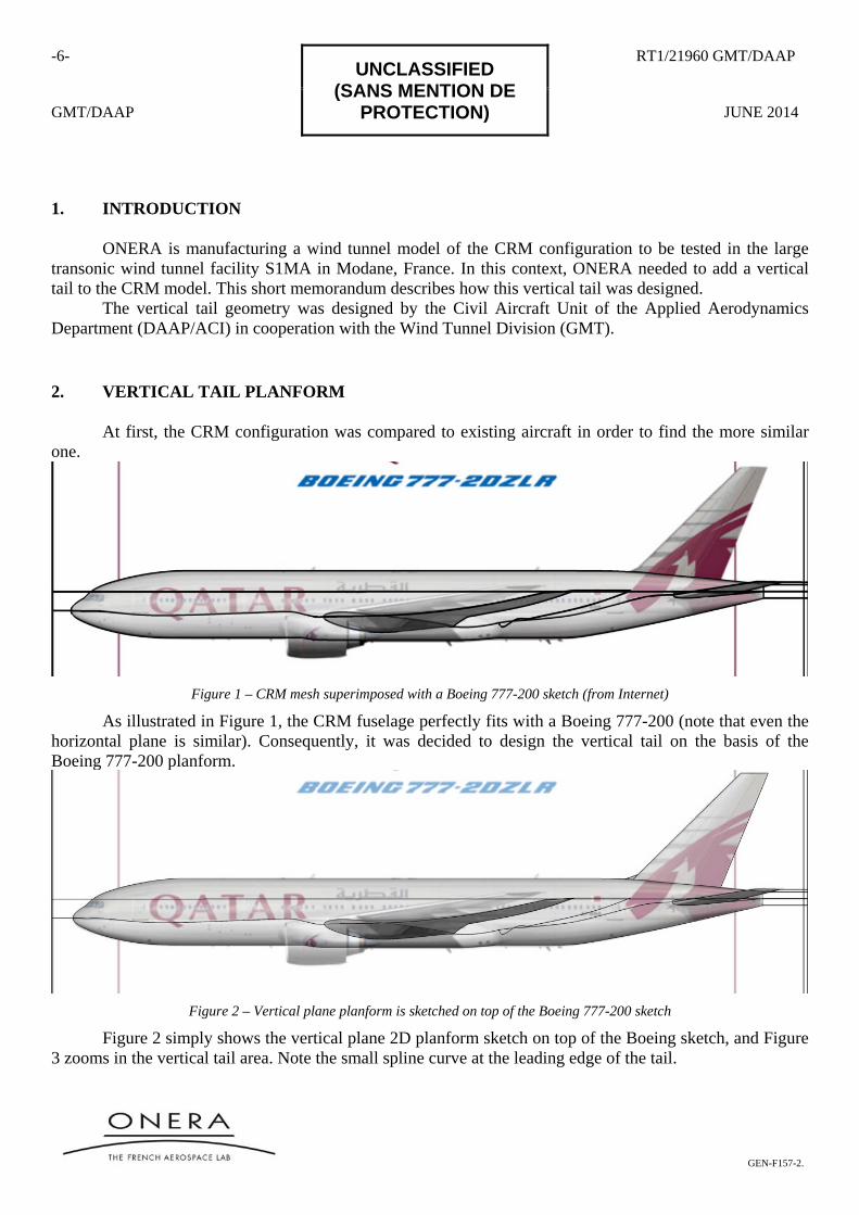
Figure 3 – Resulting planform for the vertical tail (left), small cavity in the rear fuselage (right)
Please note also that the local small and long functional area existing on the upper aft fuselage of the CRM model, which perfectly correspond to the location of the vertical tail of the Boeing 777-200 (on which this area is slightly visible too). This small area was probably designed to partialy compensate the volume effect of the vertical tail on the fuselage, thus mitigating local drag rise and flow separation risk.
The resulting tail planform has: - a projected surface of 56 m² - a tip chord of 5 104 mm - a root chord of 7 935 mm - a leading edge sweep angle of 44.5° - a trailing edge sweep angle of 22.2° - a 25% chord sweep angle of 40° - an height of approximately 10 m
3. VERTICAL TAIL AERODYNAMIC AIRFOIL
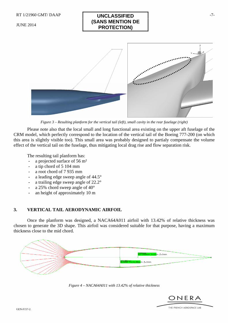
Once the planform was designed, a NACA64A011 airfoil with 13.42% of relative thickness was chosen to generate the 3D shape. This airfoil was considered suitable for that purpose, having a maximum thickness close to the mid chord.
Figure 4 – NACA64A011 with 13.42% of relative thickness
-8- UNCLASSIFIED
(SANS MENTION DE PROTECTION)
RT1/21960 GMT/DAAP
GMT/DAAP JUNE 2014
GEN-F157-2.
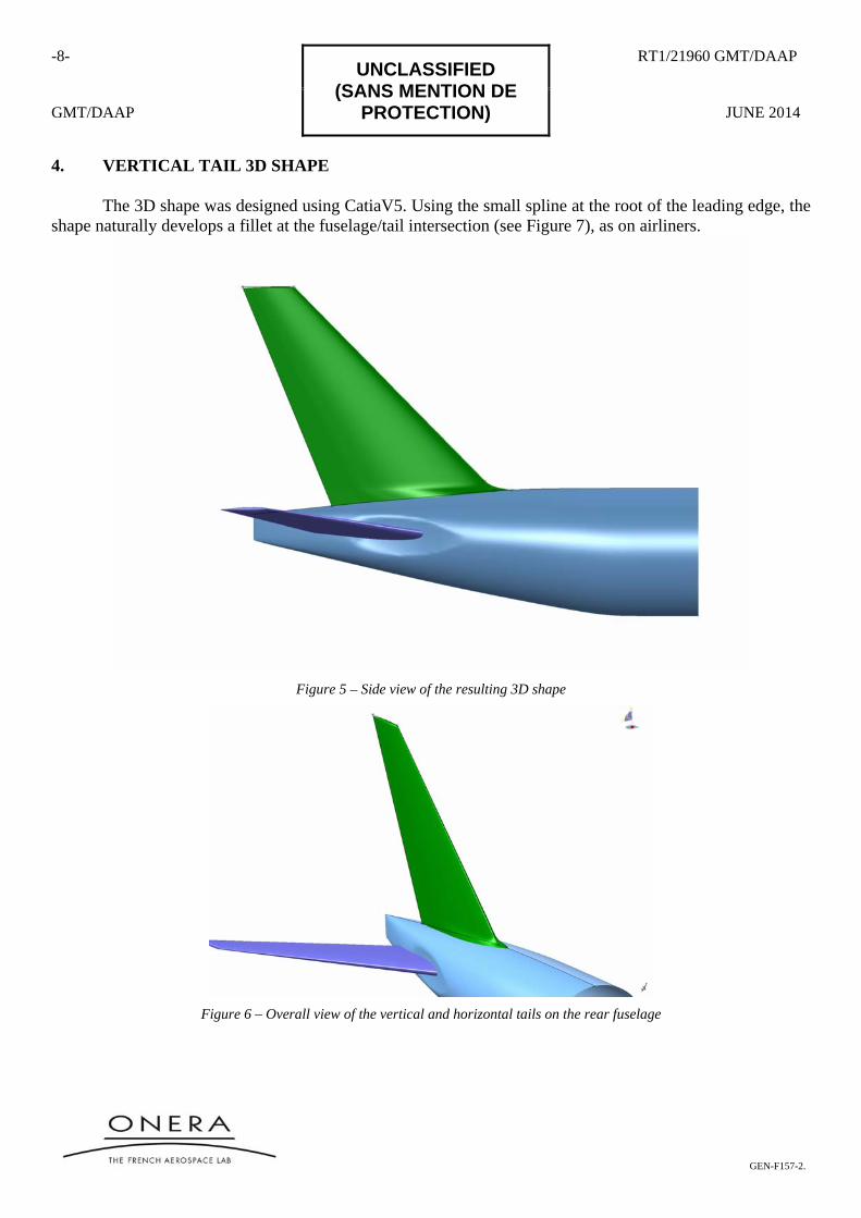
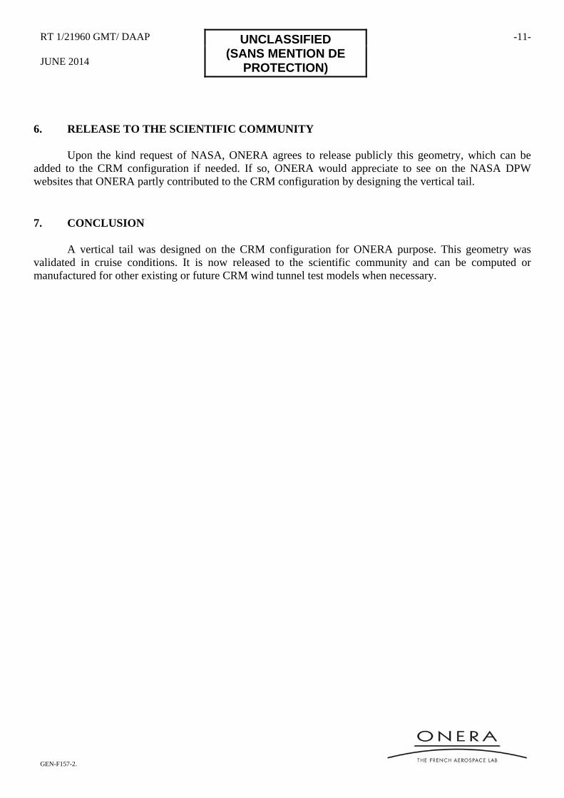
4. VERTICAL TAIL 3D SHAPE
The 3D shape was designed using CatiaV5. Using the small spline at the root of the leading edge, the shape naturally develops a fillet at the fuselage/tail intersection (see Figure 7), as on airliners.
Figure 5 – Side view of the resulting 3D shape
Figure 6 – Overall view of the vertical and horizontal tails on the rear fuselage

RT 1/21960 GMT/ DAAP UNCLASSIFIED (SANS MENTION DE
PROTECTION)
-9-
JUNE 2014
GEN-F157-2.
Figure 7 – Zoom in on the tail/fuselage intersection (front view)
Finally, a smoothed rounded wing tip was added, staying inside the tail planform (Figure 8).
Figure 8 – Vertical tail tip design
5. CFD ANALYSIS
The vertical tail was added to an existing CRM mesh with Chimera grid technique, and computed with ONERA’s elsA CFD code, solving the RANS equations with the Spalart-Allmaras turbulence model.
Flight conditions used are as follow: • Mach number 0.85 • Reynolds number based on chord: 5 millions • Angle of attack: 2.20° (lift coefficient close to 0.50) • Reference surface :191.8445 m²
The resulting computation does not show any issue on the vertical tail. The flow is clean and the
pressure distribution smooth on the vertical tail, and even at the tail/fuselage intersection (see Figure 9 and Figure 10). A very tiny and non relevant flow separation can be observed at the very end of the tail, keeping in mind that the Spalart-Allmaras turbulence model was used and is known to magnify flow separation.

-10- UNCLASSIFIED
(SANS MENTION DE PROTECTION)
RT1/21960 GMT/DAAP
GMT/DAAP JUNE 2014
GEN-F157-2.
Figure 9 – Friction lines and friction modulus on the vertical tail : no flow separation
Figure 10 – Zoom in on the trailing edge : a tiny and non-relevant flow separation can be observed (right)
Therefore the vertical tail design was considered acceptable for wind tunnel test.
RT 1/21960 GMT/ DAAP UNCLASSIFIED (SANS MENTION DE
PROTECTION)
-11-
JUNE 2014
GEN-F157-2.
6. RELEASE TO THE SCIENTIFIC COMMUNITY
Upon the kind request of NASA, ONERA agrees to release publicly this geometry, which can be added to the CRM configuration if needed. If so, ONERA would appreciate to see on the NASA DPW websites that ONERA partly contributed to the CRM configuration by designing the vertical tail.
7. CONCLUSION
A vertical tail was designed on the CRM configuration for ONERA purpose. This geometry was validated in cruise conditions. It is now released to the scientific community and can be computed or manufactured for other existing or future CRM wind tunnel test models when necessary.