design of an improved compression garment system number: klb-0802 design of an improved compression...
TRANSCRIPT

Project Number: KLB-0802
Design of an Improved Compression Garment System
A Major Qualifying Project Report submitted to the faculty of
WORCESTER POLYTECHNIC INSTITUTE in partial fulfillment of the
requirements for the Degree of Bachelor of Science
Submitted by:
Amanda DeBaie
Ashley Goncalo
David Nelson
Michael Susienka
Approved by:
______________________________
Prof. Kristen Billiar, Advisor
1. Compression bandage
2. Edema
3. Tension

i
Table of Contents
Table of Contents ............................................................................................................................. i Authorship...................................................................................................................................... iii Acknowledgments.......................................................................................................................... iv Abstract ........................................................................................................................................... v Table of Figures ............................................................................................................................. vi
Table of Tables ............................................................................................................................. vii Table of Equations .......................................................................................................................... 1 Chapter 1. Introduction ............................................................................................................... 2 Chapter 2. Literature Review...................................................................................................... 4
2.1 Significance of Compression Therapy ............................................................................ 4
2.2 Pathophysiology of Chronic Venous Insufficiency ........................................................ 5 2.3 Review of Existing Compression Therapies ................................................................... 7
2.4 Disadvantages of Existing Compression Therapies ........................................................ 9
Chapter 3. Project Strategy ....................................................................................................... 12 3.1 Initial Client Statement ................................................................................................. 12 3.2 Objectives ..................................................................................................................... 12
3.3 Ranking Objectives ....................................................................................................... 13 3.4 Functions ....................................................................................................................... 14
3.5 Constraints .................................................................................................................... 14 3.6 Specifications ................................................................................................................ 15 3.7 Project Approach .......................................................................................................... 15
Chapter 4. Alternative Designs ................................................................................................. 16
4.1 First Iteration: Novel Compression Garments .............................................................. 17
4.1.1 Conceptual Designs for Novel Compression Garments ......................................... 17 4.1.2 Feasibility Study of Novel Garment Ideas .............................................................. 20
4.2 Second Iteration: Compression Stocking Applicators .................................................. 21 4.2.1 Conceptual Designs for Compression Stocking Applicators .................................. 21 4.2.2 Feasibility Study of Stocking Applicators .............................................................. 22
4.3 Third Iteration: Compression Wrap Applicator ............................................................ 24 4.3.1 Feasibility Study of Wrap Applicator ..................................................................... 25
Chapter 5. Final Design ............................................................................................................ 26 5.1 Relating Tension and Pressure ...................................................................................... 26 5.2 Bandage Selection ......................................................................................................... 27
5.3 Tension Measurements ................................................................................................. 27 5.4 Development of Preliminary Design ............................................................................ 29
5.5 Prototype Manufacturing .............................................................................................. 31 5.6 Clutch Selection ............................................................................................................ 32
5.7 Final Design Manufacturing ......................................................................................... 32 5.8 Clutch Calibration ......................................................................................................... 35
Chapter 6. Design Verification ................................................................................................. 39 6.1 Clutch Calibration and Tension Verification ................................................................ 39 6.2 Pressure Verification ..................................................................................................... 43
Chapter 7. Discussion ............................................................................................................... 45 7.1 Tension Verification ..................................................................................................... 45

ii
7.2 Pressure Verification ..................................................................................................... 46
7.3 Limitations of the Wrapplicator .................................................................................... 47 7.4 Economic Impact .......................................................................................................... 48 7.5 Environmental Impact ................................................................................................... 48
7.6 Societal Influence ......................................................................................................... 48 7.7 Political Ramifications .................................................................................................. 49 7.8 Ethical Concerns ........................................................................................................... 49 7.9 Health and Safety Issues ............................................................................................... 49 7.10 Manufacturability .......................................................................................................... 49
7.11 Sustainability ................................................................................................................ 49 Chapter 8. Conclusions and Recommendations ....................................................................... 50
8.1 Conclusions ................................................................................................................... 50 8.2 Future Recommendations ............................................................................................. 51
References ..................................................................................................................................... 52 Appendix A. Patent Review ...................................................................................................... 54
Inflatable compression garments ............................................................................................... 54 Strap-based compression garments ........................................................................................... 54
Miscellaneous compression garments ....................................................................................... 55 Compression stocking applicators ............................................................................................. 56
Appendix B. Pairwise Comparison Charts (Initial) .................................................................. 57
Appendix C. Weighted Objectives Tree (Initial) ...................................................................... 61 Appendix D. Numerical Evaluation Matrix (Initial)................................................................. 62
Appendix E. Spring Specifications........................................................................................... 63 Appendix F. SolidWorks Drawings ......................................................................................... 64 Appendix G. Budget ................................................................................................................. 69

iii
Authorship
Author/Editor Chapter 1. Introduction ............................................................................................................................. AG/DN
Chapter 2. Literature Review 2.1 Significance of Compression Therapy............................................................................................. AG/MS 2.2 Pathophysiology of Chronic Venous Insufficiency ......................................................................... DN/MS 2.3 Review of Existing Compression Therapies .................................................................................... AG/MS 2.4 Disadvantages of Existing Compression Therapies ......................................................................... AG/MS
Chapter 3. Project Strategy 3.1 Initial Client Statement .................................................................................................................... AD/DN 3.2 Objectives ................................................................................................................................. AD/AG,DN 3.3 Ranking Objectives .................................................................................................................. AD/AG,DN 3.4 Functions ................................................................................................................................. AG/AD,DN 3.5 Constraints ....................................................................................................................................... AG/DN 3.6 Specifications .......................................................................................................................... AD/AG,DN 3.7 Project Approach ...................................................................................................................... AD/AG,DN
Chapter 4. Alternative Designs 4.1 First Iteration: Novel Compression Garments ................................................................................. DN/AD
4.1.1 Conceptual Designs .................................................................................................................. DN/AD 4.1.2 Feasibility Study of Novel Garment Ideas................................................................................ DN/AD
4.2 Second Iteration: Compression Stocking Applicators ..................................................................... DN/AD 4.2.1 Conceptual Design: Poloidal Toroid Applicator ...................................................................... DN/AD 4.2.2 Feasibility Study of Stocking Applicators ................................................................................ DN/AD
4.3 Third Iteration: Compression Wrap Applicator ............................................................................... DN/AG 4.3.1 Feasibility Study of Wrap Applicator ....................................................................................... DN/AG
Chapter 5. Final Design 5.1 Relating Tension and Pressure ........................................................................................................ MS/AD 5.2 Bandage Selection ........................................................................................................................... MS/AD 5.3 Tension Measurements .................................................................................................................... MS/AD 5.4 Development of Preliminary Design ............................................................................................... MS/AD 5.5 Prototype Manufacturing ................................................................................................................. MS/AD 5.6 Spring Selection .............................................................................................................................. MS/AG 5.7 Clutch Selection .............................................................................................................................. MS/AG 5.8 Final Design Manufacturing ............................................................................................................ MS/AG 5.9 Clutch Calibration ........................................................................................................................... DN/AG
Chapter 6. Design Verification 6.1 Clutch Calibration and Tension Verification ................................................................................... DN/AD 6.2 Pressure Verification ....................................................................................................................... DN/AG
Chapter 7. Discussion 7.1 Tension Verification ........................................................................................................................ MS/AD
7.2 Pressure Verification ....................................................................................................................... DN/AG
7.3 Limitations of the Wrapplicator ...................................................................................................... AG/DN
7.4 Economic Impact ............................................................................................................................. AG/AD 7.5 Environmental Impact ..................................................................................................................... AG/AD 7.6 Societal Influence ............................................................................................................................ AG/AD 7.7 Political Ramifications .................................................................................................................... AG/AD 7.8 Ethical Concerns .............................................................................................................................. AG/AD 7.9 Health and Safety Issues .................................................................................................................. AG/AD 7.10 Manufacturability ............................................................................................................................ AG/AD 7.11 Sustainability ................................................................................................................................... AG/AD
Chapter 8. Conclusions and Recommendations 8.1 Conclusions ..................................................................................................................................... AD/DN 8.2 Future Recommendations ................................................................................................................ AD/MS

iv
Acknowledgments
Our team would like to thank our advisor, Prof. Kristen Billiar, for his continuous support
throughout our MQP process. We also would like to express our gratitude to our clients, Dr.
Gary Fudem and Dr. Janice Lalikos from UMass Medical School, in addition to the technicians
and doctors from the UMass Wound Clinic. Finally, we would like to thank the WPI faculty and
staff, specifically, Prof. Jianyu Liang, Prof. Satya Shivkumar, Neil Whitehouse, and Krystyna
Gielo-Perczak for providing us with their knowledge and expertise.
v
Abstract
Compression garments are the standard of treatment for lessening the impact of the sequelae
associated with chronic venous insufficiency, which affects 30% of the adult population.
Unfortunately, there are several limitations with compression garments, specifically their
clinician dependence and resulting compression variability. The purpose of this project was to
design an improved compression garment system that provides reproducible compression, is
reusable, and can be applied at home by a patient or caretaker. To realize these objectives, a
compression bandage applicator that controls bandage tension during application was designed,
manufactured, and tested. The final design applies 1.48-2.95 lbf of bandage tension and can be
adjusted for different leg sizes. This bandage tension was shown to produce 24.7-30.7 mmHg of
graded pressure, which is more clinically acceptable than the pressure theoretically being
achieved in the clinic. Additionally, it can be used at home by a patient or caretaker, which
could greatly improve the quality of life for the patient.

vi
Table of Figures
Figure 1: Patient affected by chronic venous insufficiency ............................................................ 4 Figure 2: Venous ulcer as a result of severe edema ........................................................................ 5 Figure 3: Normal functioning valves vs. faulty valves ................................................................... 6 Figure 4: Compression stockings .................................................................................................... 8 Figure 5: Four-layer bandage system .............................................................................................. 9
Figure 6: Unna's boot ...................................................................................................................... 9 Figure 7: Diagram of iterations of conceptual designs ................................................................. 17 Figure 8: Stress vs. strain curve for Nitinol with superelasticity highlighted ............................... 18 Figure 9: Superelastic garment ..................................................................................................... 18 Figure 10: Heat-shrinkable shape memory polymer ..................................................................... 19
Figure 11: Image of a toroid with red and blue arrows indicating poloidal and toroidal direction,
respectively ................................................................................................................................... 21
Figure 12: Poloidal rolling toroid stocking applicator .................................................................. 22
Figure 13: CAD model of rigid toroid stocking applicator ........................................................... 23 Figure 14: CAD model of rigid cylindrical lipped stocking applicator ........................................ 24 Figure 15: Notebook sketch of the Wrapplicator preliminary design ........................................... 25
Figure 16: How sub-bandage pressure changes with leg radius if bandage tension remains
constant ......................................................................................................................................... 26
Figure 17: Plot of tension vs. Green strain for Profore #3 bandage ............................................. 28 Figure 18: Plot of bandage tension measurements at ankle, mid-calf, and knee in the clinic ...... 29 Figure 19: SolidWorks model of preliminary design ................................................................... 30
Figure 20: SolidWorks model of preliminary design with Profore #3 bandage ........................... 30
Figure 21: SolidWorks model of housing with ball bearing and clutch ....................................... 33
Figure 22: SolidWorks model of PVC spool with aluminum end caps ........................................ 34 Figure 23: Exploded view of final design ..................................................................................... 34
Figure 24: Photograph of final design .......................................................................................... 35 Figure 25: Photograph of clutch set to higher tension for lower half of leg ("green ankle" setting)
....................................................................................................................................................... 36
Figure 26: Photograph of clutch set to lower tension for upper half of leg (―green calf‖ setting) 36 Figure 27: Forces in a bisected cross section of the leg, assuming a frictionless cylindrical solid
....................................................................................................................................................... 38 Figure 28: Instron tensile testing................................................................................................... 39 Figure 29: Force vs. extension curve for blue ankle setting ......................................................... 40
Figure 30: Force vs. extension curve for green ankle setting ....................................................... 40 Figure 31: Force vs. extension curve for orange ankle setting ..................................................... 41
Figure 32: Force vs. extension curve for blue calf setting ............................................................ 42 Figure 33: Force vs. extension curve for green calf setting .......................................................... 42
Figure 34: Force vs. extension curve for orange calf setting ........................................................ 43 Figure 35: Water calibration of the pressure transducer via submersion of the pressure pad ...... 43 Figure 36: Sub-bandage pressure measured at ankle after application via Wrapplicator ............. 44 Figure 37: Sub-bandage pressure measured at calf after application via Wrapplicator ............... 44 Figure 38: Comparing tension output of the Wrapplicator with tension measured in clinic ........ 46 Figure 39: Weighted objectives tree for design objectives and sub-objectives ............................ 61

vii
Table of Tables
Table 1: Pairwise comparison chart with Dr. Fudem's scores ...................................................... 13 Table 2: Pairwise comparison chart with Dr. Lalikos' scores ....................................................... 14 Table 3: Average scores for pairwise comparison charts ............................................................. 14 Table 4: Extension measurements during application of compression garment........................... 27 Table 5: Specifications of ball bearings from McMaster-Carr (Part Number: 6455K27) ............ 32
Table 6: Color scheme data for torque limiting clutch ................................................................. 37 Table 7: Average tensions and standard deviations for Wrapplicator and measurements from
clinic .............................................................................................................................................. 45 Chart 8: Main objectives (as weighed by team)............................................................................ 57
Chart 9: Overall weights for main objectives ............................................................................... 57 Chart 10: Easy to use/apply sub-objectives (as weighed by team) ............................................... 58 Chart 11: Overall weights for Easy to Use/Apply sub-objectives ................................................ 58
Chart 12: Patient Friendly sub-objectives (as weighed by team) ................................................. 58
Chart 13: Overall weights for Patient Friendly sub-objective ...................................................... 59 Chart 14: Efficacy sub-objectives (as weighed by team).............................................................. 59 Chart 15: Overall weights for Efficacy sub-objective .................................................................. 59
Chart 16: Safe sub-objectives (as weighed by team) .................................................................... 60 Chart 17: Overall weights for Safe sub-objectives ....................................................................... 60
Table 18: Numerical evaluation matrix for conceptual design ideas ............................................ 62 Table 19: Specifications of constant force spring from McMaster-Carr (Part Number: 9293K48)
....................................................................................................................................................... 63

1
Table of Equations
Equation 1: Sub-bandage pressure as a function of bandage tension, leg radius, and bandage
width ............................................................................................................................................. 26 Equation 2: Green strain equation ................................................................................................. 28
Equation 3: Calculations for constant-force spring selection ....................................................... 31 Equation 4: Force-equilibrium equations...................................................................................... 37 Equation 5: Pressure applied by the nurse at the clinic ................................................................ 46 Equation 6: Percentage error the nurse’s applications in the clinic .............................................. 47 Equation 7: Percentage error calculated when using the Wrapplicator ........................................ 47

2
Chapter 1. Introduction
Compression therapy is an essential treatment for a myriad of medical conditions that result in
edema. These include, but are not limited to, congestive heart failure, venous insufficiency,
venous ulcers, varicose veins, acute and chronic burns, congenital lymphedema, parasitic
diseases, and lymph node dissection. However, this project primarily focused on the treatment
of lower leg edema due to chronic venous insufficiency, a condition whose effects can be seen in
3-11% of the adult population (Nicolaides, 2000).
Chronic venous insufficiency (CVI), which refers to a group of venous disorders, is typically
characterized by the retrograde flow of blood in the lower extremity. Currently, there is an
increase in prevalence of this disorder, as an estimated 25 million people in the United States
have varicose veins, about 2 to 6 million have more advanced forms of CVI, and nearly 500,000
develop venous ulcers as a result of untreated CVI (White, 2005). The population at greatest risk
for developing CVI are those who have suffered leg trauma, have deep vein thrombosis, are
genetically predisposed, have diabetes mellitus, rheumatoid arthritis, congestive heart failure, or
renal insufficiency. Additionally, the sequelae of CVI can be found in 80% of all pregnant
women, so the implications for the female population are substantial (Bamigboye, 2006).
It is general practice to treat chronic venous insufficiency and its sequelae with some form of
compression therapy (Berliner, 2003). There are various compression treatments available, such
as graduated compression stockings, elastic and inelastic bandages, orthotic devices, and
compression pumps. These treatments, particularly those that apply graded pressure, normally
result in reduced venous pooling and improved tissue oxygenation. Studies have also shown a
significant improvement in venous function as measured by the residual volume fraction and
reflux in the affected limb (Kolarj, 1987). In the case of pregnant women, compression therapy
has been shown to improve venous pump function, slow venous refilling time, and increase
venous outflow velocities.
While existing compression therapies have the potential to effectively treat CVI, the efficacy of
these techniques is often undermined. There arise several common disadvantages amongst the
more widely used compression therapies. One of the more pertinent issues is that many
treatments are highly clinician dependent. For example, it is difficult to apply wraps with proper
compression because there is no quantitative way to measure how much compression is being
applied. Therefore, the amount of compression varies from application to application and from
clinician to clinician. Additionally, wrinkling and creasing of the bandages easily occurs even
when the most experienced clinicians apply the wraps. These wrinkles and creases can lead to
the development of sores on the skin. Another significant disadvantage is that these garments do
not maintain proper compression over time because the wrap typically loosens as the edema
decreases. This necessitates frequent visits to the wound clinic (sometimes three times a week),
which can lead to issues with patient compliance and medical resources (G. Fudem, personal
communication, September 5, 2008).
Due to the limitations of current treatments, there is a significant decrease in the quality of life
for patients suffering from CVI. This disorder is accompanied by such sequelae as night cramps,
extreme swelling (edema), heaviness of the leg, severe pain, and paraesthesiae leading to anxiety

3
(Ruckley, 1997). Oftentimes, if this condition is left without proper treatment, it can lead to
breakdown of the skin and painful ulcer formation.
The goal of this project was to address the disadvantages of current compression therapies by
developing an improved compression garment system that applies reproducible compression to
the leg, is able to be put on at home by the patient or caretaker, controls tension in the bandage as
the patient’s leg is wrapped, and is reusable.
4
Chapter 2. Literature Review
Compression therapy, in its current clinical form, has many flaws that could be improved by the
design and implementation of an improved compression garment system. In order to better
understand the critical need for compression therapy in the clinical setting, this chapter will
explain the importance of compression therapy, the effects of CVI, existing compression
therapies, and limitations with existing compression therapies.
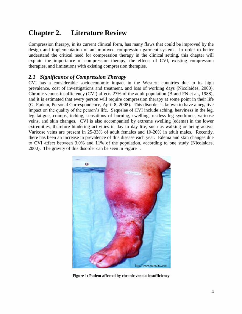
2.1 Significance of Compression Therapy CVI has a considerable socioeconomic impact in the Western countries due to its high
prevalence, cost of investigations and treatment, and loss of working days (Nicolaides, 2000).
Chronic venous insufficiency (CVI) affects 27% of the adult population (Brand FN et al., 1988),
and it is estimated that every person will require compression therapy at some point in their life
(G. Fudem, Personal Correspondence, April 8, 2008). This disorder is known to have a negative
impact on the quality of the person’s life. Sequelae of CVI include aching, heaviness in the leg,
leg fatigue, cramps, itching, sensations of burning, swelling, restless leg syndrome, varicose
veins, and skin changes. CVI is also accompanied by extreme swelling (edema) in the lower
extremities, therefore hindering activities in day to day life, such as walking or being active.
Varicose veins are present in 25-33% of adult females and 10-20% in adult males. Recently,
there has been an increase in prevalence of this disease each year. Edema and skin changes due
to CVI affect between 3.0% and 11% of the population, according to one study (Nicolaides,
2000). The gravity of this disorder can be seen in Figure 1.
Figure 1: Patient affected by chronic venous insufficiency
http://www.uptodate.com

5
Perhaps the most debilitating symptom is the occurrence of venous ulcers as a result of CVI,
shown in Figure 2. Those suffering from venous ulcers and who are also of low socioeconomic
class, of single marital status, or do not have central heating, might find that the treatment and
healing of their venous leg ulcers is significantly delayed. Additionally, the prognosis of venous
leg ulcers is poor: only 50% heal at four months, 20% remain open at two years, and 8% remain
open at five years. In one study, about 12.5% of patients with ulcers took early retirement
because the reoccurrence of the ulcers prevented their continuation of work. Another study
found that CVI is the 14th
most-frequently quoted disease for temporary work absenteeism and
the 32nd
most frequent cause of permanent disability and public financial assistance. In the
United States, the total cost of CVI (both indirect and direct) is estimated to be in excess of $1
billion dollars (Ruckley, 1997).
Figure 2: Venous ulcer as a result of severe edema
Currently, compression therapy is the standard care for treating the sequelae associated with
venous insufficiency. In the lower extremities, there are deep, communicating, and superficial
veins. These all possess one-way valves that direct blood from the superficial to the deep venous
system as a result of the pressure difference between them. The use of compression therapy
dates back to the 17th
century, when rigid lace-up stockings were used to improve circulation.
Years later, the idea of compression stockings with graded pressure was introduced. It is
generally accepted in the field that graded compression therapy is more effective than non-
graded; however, both are successful in helping to restore normal venous function (Choucair,
1998). Today, there are many types of compression therapies used to prevent or treat lower leg
edema, including graded compression stockings, multi-layer bandage systems, medicated
bandages, orthotic compression devices, and compression pumps. At the UMass Wound Clinic,
the Profore™ Multi-layer Compression System from Smith & Nephew and Unna’s boot are most
commonly used to treat lower leg edema.
2.2 Pathophysiology of Chronic Venous Insufficiency To understand how compression therapy is used to treat chronic venous insufficiency, it is
important to know some of the fundamentals of this disorder. Veins, the blood vessels that bring
deoxygenated blood back to the heart, have a ladder of valves that run along their length like a
sequence of gates. These gates compartmentalize the hydrostatic pressure of blood caused by the
vertical orientation of the veins and allow the muscles that surround the veins to assist in
Picture provided by Professor D. MacLellan Department of Surgery, Canberra Hospital
Copyright © National Prescribing Service 2008.

6
circulation by acting as pumps. Without these valves, the blood pressure at the bottom of a
person’s legs would be far greater than at the top of their legs and there would be no pumping
mechanism between the veins and leg muscles. Sometimes, the valves can become weakened or
damaged as a result of genetics, deep vein thrombosis, diabetes, pregnancy, or compression of
the left iliac vein by the right iliac artery (May-Thurner Syndrome) (Heniford, 1998). Regardless
of the cause, valve damage results in backflow, hypertension, pooling of blood, and dilation of
the veins.
Although obesity is considered a risk factor related to CVI, as well as varicose veins (VV), it is
not a documented as a direct cause for these conditions. Studies have shown that older men who
are obese are at a higher risk for developing CVI. Obese women over the age of fifty are also at
a higher risk for CVI and VV, being three times more likely to develop VV. It is still not proven
that obesity is a direct cause for developing CVI and VV, or if having CVI causes them to be
inactive and therefore overweight. Weight loss can improve a person’s condition if they are
suffering from CVI or VV; however, it is not a cure for either of these conditions (Lacroix,
2003).
CVI manifests itself into many sequelae in a vicious cycle of degrading physiological processes.
When the first venous valves begin to lose functionality, the stress that would otherwise be
relieved by proper function of those valves is added to the stress that is relieved by properly
functioning valves. Therefore, starting from the onset of valvular dysfunction, valvular
degradation accelerates unless physiological conditions are improved. The hydrostatic pressure
that the venous valves would otherwise prevent causes excess blood to flow from the deep veins
into the peripheral veins, which results in varicose veins (i.e. spider veins). Hypertension in the
venous walls also causes dilation of the veins, which further reduces valvular efficiency and
causes turbulent flow of blood in that section of the vein. As a result of this turbulent flow,
deoxygenated blood cells can linger in some areas of the vein for longer periods of time than
others, which reduces the efficiency of circulation in that area. Figure 3 demonstrates the
difference between normal venous function and faulty venous function.
Figure 3: Normal functioning valves vs. faulty valves
When the efficiency of circulation is reduced, the surrounding tissue that is fed by the blood
vessels begins to die. Scar tissue begins to replace the dead tissue surrounding the blood vessels,
essentially replacing healthy tissue with dry, poorly vascularized, rough tissue. This scar tissue
https://services.epnet.com/GetImage.aspx/getImage.aspx?ImageIID=7616
(https://services.epnet.com/GetImage.aspx/getImage.aspx?ImageIID=7616
)

7
has poor tissue mechanics, leaving it more susceptible to damage in the event that the tissue
sustains physical impact damage (e.g. if the patient bumps his or her leg on a hard surface). In
this case, a wound will form, but it will not bleed the way a wound normally would because scar
tissue is poorly vascularized. Therefore, the wound does not receive the antibodies and organic
molecules necessary to quickly heal the wound, leaving it vulnerable to infection over a much
longer healing period (Valencia, 2001).
The reflux and venous congestion of blood that result from CVI is the cause of many major
sequelae, most commonly but not limited to edema and discomfort. In the foot and lower ankle
region, the deep venous system is in very close proximity with the distal venous system. This
proximity allows for easy shifts of hypertensive pressure to the subcutaneous blood vessels,
which, having minimal amounts of supportive connective tissue surrounding them, are meant to
sustain lower pressures. This commonly results in distal skin changes, inflammation,
subcutaneous fibrosis, and ulceration (White, 1996). The visual signs of CVI can include the
presence of varicose veins, mild to moderate edema mostly in the distal calf and foot, darkening
of the perimalleolar skin, dry, scaling of skin of the calf and foot, and sometimes venous ulcers
near the malleoli. The pain resulting from CVI can come in the form of aching, throbbing,
stinging leg pain after standing for extended periods of time or soon after lying down, restless
legs, muscle cramps, or any combination of those.
To alleviate the sequelae of CVI, compression garments have been generally accepted as the
foundation of therapy. The means by which compression garments improve the conditions of
CVI are by reduction in surface area of the leg, decreased venous pooling, and limitation of
retrograde flow. These claims have been validated by studies by G.D. Motykie et al., 1999, Agu
et al., 2004, Ibegbuna et al., 2003, and Buchtemann et al., 1999.
2.3 Review of Existing Compression Therapies The use of graded compression stockings, as seen in Figure 4, has proven effective – there is
generally a fall in ambulatory venous pressure accompanied by a rise in the expelled calf volume
upon exercise. Each garment has a standard compression value, which is graded up the leg so
that there is more pressure at the bottom and this pressure lessens upon moving up the leg.
Generally there are four classes of compression stockings. Compression class I stockings apply
a pressure of 20-30 mmHg and are recommended for treatment of patients with varicose veins,
minimal edema, and leg fatigue. Compression class II stockings apply a pressure of 30-40
mmHg and are used for the treatment of moderate edema and moderate venous insufficiency.
Class III stockings apply a pressure of 30-50 mmHg, and class IV stockings (60+ mmHg) are
utilized in extreme cases of edema, venous insufficiency, and elephantiasis (O’Meara, 2008).

8
Figure 4: Compression stockings
Because patients using compression stockings are often elderly, obese, or suffer from arthritic
joints, donning a compression stocking proves to be a challenge. To overcome such challenges,
compression stocking applicators are utilized when the user is applying the compression
stocking. These are several marketed designs for such applicators. Generally, the dimensions of
the applicators are larger than that of the leg, to allow for minimal sheering and easier
maneuverability. The stockings are typically connected to or fitted around the applicator,
applied to the leg using the applicator, and then the applicator is removed, leaving the
compression stocking on the user’s leg. Despite the different designs, the overall purpose of
these applicators is to require less force and exertion from the patient when donning the stocking
(O’Meara, 2008).
A four-layer bandage (or wrap) system (e.g. the Profore™ Multi-layer Compression Bandage
System from Smith & Nephew) is another type of compression garment, where four layers of
bandage are used to effectively apply graded pressure to a patient’s leg. There is a wound
contact layer which should be placed on the leg before the four layers. The first layer is a natural
padding bandage, the second is a light conformable dressing, the third is a light compression
bandage, and the fourth is a flexible cohesive bandage. The third layer is responsible for
applying the bulk of the compression. The third layer is applied at mid-stretch, in figure eight
patterns with 50% overlap. The fourth layer keeps the garment in place for up to a week
(optimal time). Typical four layer bandages can provide up to 40 mmHg pressure, depending on
the technician applying the bandage. This type of garment is displayed below, in Figure 5.
http://www.shopmedrx.com

9
Figure 5: Four-layer bandage system
The Unna’s boot is a medicated bandage containing zinc oxide, calamine, glycerine, sorbitol, and
magnesium silicate. It is often used as a substitute for a failing muscle pump, since its inelastic
property simulates a pumping force at the ankle joint. This boot creates a pressure gradient of
approximately 30 mmHg at the medial malleolus, which decreases towards the knee. This is
typically the treatment for patients suffering from venous ulcers, due to the fact that they protect
the wound against trauma while simultaneously coating the wound with medication.
Figure 6: Unna's boot
2.4 Disadvantages of Existing Compression Therapies To understand the importance of designing an improved compression garment system, it is
helpful to identify the numerous problems associated with current compression therapies in
clinical use. Unfortunately, it is virtually impossible to isolate one distinct fundamental problem
with existing therapies because there is a myriad of individual factors that contribute to the
overall problem. The most pertinent disadvantages, which will be further elaborated upon,
include:
http://www.devotedmedicalsupply.com
http://www.medscape.com

10
Application of compression wraps is highly technician dependent
Clinicians often apply non-uniform tension during the application of compression
bandages
Compression wraps do not maintain consistent pressure over time
Compression wraps can only be put on by trained technicians
Compression garments can potentially compromise the quality of life for patients
Compression stockings are difficult to don
Compression stockings can cause shearing on the leg
The goal of this project is to design, construct, and evaluate a novel compression garment system
that addresses the most prominent disadvantages.
One of the major problems associated with existing compression garments is the fact that their
application is highly technician dependent. For instance, when using compression wraps, the
amount of created compression varies significantly between different applications and between
the clinicians who apply these wraps. Currently, there is no quantitative method for the clinician
to measure exactly how much tension is in the bandage when he or she is applying the wrap to
the patient’s leg. Since the amount of pressure is related to the tension of the bandage (Section
5.1), there is no way of quantitatively knowing the amount of compression on the leg without the
insertion of a pressure transducer. Moreover, it was found through data obtained when visiting
the UMass Wound Clinic that the clinician was applying a non-uniform tension to the bandage
while wrapping. Because there is non-uniform tension in the wraps, this can cause pressure
concentrations, which can result in wounds due to the fragility of the patients’ skin. The
inconsistencies in bandage tension can be seen in Section 5.3. Another problem with existing
wraps is that they are not able to maintain consistent pressure over time. As the excess fluid
gradually recedes from the edemic tissue, the compression garment loosens to the point where it
is no longer applying effective pressure. This loosening can also lead to wrinkles and creasing.
Furthermore, the compression garment can slide down the leg and bunch up, particularly around
the ankle, which can exacerbate the problem by inducing a tourniquet effect (Chocair, 1998).
Additionally, compression wraps can only be put on by trained medical clinicians. Therefore,
whenever a patient needs to have their leg re-wrapped, they must visit the clinic. Increased clinic
visits can impact the patient’s medical insurance and personal spending, and more importantly,
their quality of life. Because these wraps need to be left on for periods of time, this makes
normal daily activities, such as bathing, very difficult. In general, compression garments are not
very comfortable due to their lack of breathability. This is especially problematic during hot or
humid weather conditions, when they often become rather hot and moist. This wetness, along
with the fact that the skin and garment cannot be cleaned, often results in the development of a
pungent odor. Problems such as these contribute significantly to the larger problem of patient
compliance. For instance, it is not uncommon for patients to remove their compression wraps
earlier than their physicians instruct them to do so, if at all. As previously mentioned, this
requires the patient to wait for their next appointment with the physician, which is
disadvantageous to the healing process (Chocair, 1998).
Regarding compression stockings, while these are more effective in providing consistent graded
pressure on the leg, they are very difficult to don, especially for those patients who are obese,
have arthritic joints, or are elderly. Also, these stockings induce a great deal of shear stress on

11
the leg when they are applied. This is problematic for patients who have venous ulcers or burn
wounds on their legs because the application of the stocking has the potential to disturb these
wounds. In order to address these disadvantages, several applicators and application methods
have been marketed. However, many of these applicators are bulky and difficult to use (Chocair,
1998).

12
Chapter 3. Project Strategy
The purpose of this section is to detail the engineering design process that we exercised in order
to conceive our final design for an improved compression garment system. This procedure was
adapted from the book Engineering Design: A Project-Based Introduction by Clive L. Dym and
Patrick Little.
3.1 Initial Client Statement Dr. Gary Fudem and Dr. Janice Lalikos, our clients from UMass Medical School, wrote the
following description of our project, which we considered to be our initial client statement:
Compression therapy is essential for many medical conditions. These include—
but are not limited to—varicose veins, venous ulcers, congestive heart failure,
acute and chronic management of burns, diabetic ulcers, congenital lymphedema,
acquired lymphedema secondary to radiation injury, lymph node dissection,
parasitic diseases, and life threatening bleeding in a war zone. These diseases
have a broad reach, affecting all ages in all types of communities; compression
therapy is a vital treatment for billions of people worldwide and over one hundred
million in the United States. This project involves the design of a new
compression garment. An ideal pressure garment would be easy to apply,
disposable or readily washable, breathable, conform to irregular surfaces and
able to be coated with medication or permit the application of a medicated
dressing on open wounds, all while maintaining an effective pressure distribution.
Given that nearly every person in the world will require compression therapy at
some time in their life, and that current treatment mediums are nearly always
inadequate, developing a product that applies effective pressure in a uniform and
reproducible way is of the utmost importance.
3.2 Objectives The objectives for the project were developed based on our research of chronic venous
insufficiency (CVI), meetings with our advisors, and meetings with our clients from UMass
Medical School. The four original objectives decided on were: easy to use/apply, patient
friendly, effective in treating chronic venous insufficiency, and safe. However, while going
through the primary phase of the design process, we deemed it necessary to narrow the scope of
the broad project goal we initially had. This required the revisitation of the project approach
phase, where we conducted additional research and meetings with our clients. After several
iterations, we developed these three final objectives, ranked in order of importance:
1. Able to be put on at home by patient or caretaker
2. Maintains constant tension in the bandage, therefore creating a pressure gradient up the
leg
3. Reusable compression system
The ability for the patient to apply the compression garment system at home without the aid of a
medical professional was the most important objective. As previously mentioned, the
13
compression wrap system utilized by our clients is highly technician dependent. Specifically,
whenever the patient needs their leg re-wrapped, they must go into the clinic to have a trained
medical professional do so. Therefore, if the patient or a caretaker had the ability to wrap the
patient’s leg at home, this would decrease the number of visits the patient makes to the clinic
during the week. Also, by affording a patient or caretaker the ability to apply compression
garment system at home, they could perform daily activities such as bathing, because they would
no longer need to rely on visiting the clinic to have the garment reapplied.
The design should also be able to maintain constant tension in the wrap while it is being applied
to a patient’s leg. This creates a pressure gradient up the leg that is more effective than non-
graded compression in treating the sequelae associated with CVI (Jorgensen, 2005). The
pressure gradient (higher pressure at the ankle, lower pressure near the knee) is achieved because
pressure is inversely proportional to radius, the relationship for which can be seen in Section 5.1.
Our final objective was for our design to be reusable. Currently, patients must go into the clinic
every time they need their leg wrapped. Therefore, by creating a design that is be reusable, this
would provide an easier method for the patient to receive treatment without frequent visits to the
clinic. Additionally, a reusable garment system would likely be financially beneficial to both the
clinic and the patient.
3.3 Ranking Objectives In order to evaluate the conceptual designs, it was necessary to weigh the objectives to
distinguish which were more significant than others. An ideal design would better satisfy the
more essential objectives than those of lesser importance. To help accomplish this, pairwise
comparison charts were used to set precedence of the objectives. A pairwise comparison chart is
an engineering tool that quantifies and orders the primary and sub-objectives.
As mentioned, we went through several iterations of our objectives and thus sub-objectives.
Each time, pairwise comparison charts of these objectives were formulated. These can be found
in Appendix B. The final iteration of our objectives and their respective weights can be seen
below in Table 1 through Table 3.
Table 1: Pairwise comparison chart with Dr. Fudem's scores
Able to be put on
at home by
patient or
caretaker
Reusable Maintains
constant tension Total
Able to be put on at
home by patient or
caretaker
x 1 1 2
Reusable 0 x 0 0
Maintains constant
tension 0 1 x 1

14
Table 2: Pairwise comparison chart with Dr. Lalikos' scores
Able to be put on
at home by
patient or
caretaker
Reusable Maintains
constant tension Total
Able to be put on at
home by patient or
caretaker
x 0 1 1
Reusable 0 x 0 0
Maintains constant
tension 0 1 x 1
Table 3: Average scores for pairwise comparison charts
Objective Average
Able to be put on at home by patient or caretaker 1.5
Maintains constant tension 1
Reusable 0
3.4 Functions The primary function of this compression garment system was to apply constant tension in order
to receive graded pressure from the ankle to the knee of the patient. Many garments apply
pressure with an even distribution; however, there has been much research which suggests
graded pressure is more effective in treating CVI, since it reduces ambulatory venous pressure in
the leg (Horner, 1980). Due to these findings, we wanted the garment to apply graduated
compression by maintaining uniform circumferential tension up the leg until a new garment is
reapplied. Also, this garment system would ideally be applicable to a variety of leg sizes.
3.5 Constraints Constraints are limits that enable designers to identify and exclude unacceptable designs. These
included a time constraint (completion before April 30, 2009 or approximately 8 months), and a
budgetary constraint of approximately $600. Additionally, patient safety is a constraint as the
garment system cannot cause harmful side effects, which may result from shearing during
application or lack of breathability.
As previously discussed, an issue with current garments, particularly compression stockings,
includes the difficulty of application. Thus, the garment inadvertently causes shearing, a
potential problem if the patient has weak skin, a venous ulcer, or some other wound; this
constraint limits the design space for potential conceptual ideas. Our client specified that the
garment system would be unmarketable if it is overpriced. Therefore, we feel that if the
prototype falls within our project budget and we can prove that our design will be more
functional than current compression practices, further insight into the actual development of our
product could lead to mass production, reducing the cost of the garment system for patients. For

15
that reason, price of the garment system was only to be considered a constraint if the project
team could not afford to manufacture a prototype with the allotted $600 budget.
3.6 Specifications The final specifications for our design are closely related to the functions we set for our project.
The main function that our design must follow is that it provides constant tension on the leg, and
therefore provides a pressure gradient. As stated earlier, our group found that clinicians at the
UMass Wound Clinic were applying inconsistent tension when wrapping patient’s legs (Section
5.3). This variation was found not only from patient to patient, but also from clinician to
clinician, and the inaccuracy (from the ideal 20-30 mmHg pressure) of these tensions
theoretically approached 80% error (Section 7.2). Therefore, the device should not have greater
than 25% error of the desired range of compression, 20-30 mmHg, with the calf at a lower level
of compression than the ankle.
Additionally, this device needs to meet certain physical specifications such as maximum weight
capacity, size, and strength required to use the device. These specifications were decided based
on the estimated capabilities of a typical nurse in the clinic. A nurse should not be expected to
use a device more cumbersome than 2.5 pounds and should not have to push or pull with more
than five pounds of force using either arm. Furthermore, if the device has a handle, the handle
needs to be large enough to accommodate the hand of a person, which would not be expected to
be wider than 4.5 inches.
Finally, one of our objectives is for the patient to be able to use our design at home themselves or
with the aid of a caretaker. In order for our device to be useful for many patients, it needs to be
adjustable to fit the needs of patients with differing leg sizes. This would allow virtually all
patients to use the design in the home setting simply by adjusting the device to fit their needs.
3.7 Project Approach After adjusting the objectives based on the client’s need and ultimately narrowing the scope of
the project, it was necessary to revise the client statement. The revised client statement is as
follows:
We need to design, construct, and evaluate a novel compression garment system
that can be applied at home by the patient or caretaker. This garment system
should control the tension in the bandage, thereby creating a pressure gradient
up the leg, and be reusable.
This goal helped us to develop our conceptual designs, evaluate those designs, and select a final
design to pursue and implement.

16
Chapter 4. Alternative Designs
After several early interviews with our clients at UMass Medical School, we developed our
initial functions, objectives, and constraints of our design in order to brainstorm conceptual
designs. In this initial design phase, six unique conceptual designs were selected as potential
candidates for our preliminary design. These alternative designs primarily focused on
developing a completely novel compression garment that met our initial objectives. These
included compression garments that incorporated inflatable chambers, a heat-shrinkable shape
memory polymer, a spray-on garment, and woven superelastic materials. Additionally, several
innovations to existing wraps and garments were devised.
After determining that these initial conceptual designs were infeasible, we refined our design
objectives, functions, and constraints and shifted our focus to designing a compression stocking
applicator. Unfortunately, none of the compression stocking applicator ideas met these
objectives, functions, and constraints, so we moved on to the third iteration of our project, which
was to design a compression bandage applicator. A summary of these multiple iterations can be
seen in Figure 7.

17
Figure 7: Diagram of iterations of conceptual designs
4.1 First Iteration: Novel Compression Garments
4.1.1 Conceptual Designs for Novel Compression Garments
Superelastic Garment
The team’s first design idea was to incorporate a superelastic material, such as Nitinol (nickel-
titanium alloy), into the weave of a typical compression garment. A superelastic material would
be ideal because it allows for the pressure created by the garment to remain constant even as the
swelling of the leg diminishes. Due to its unique material properties, Nitinol maintains a constant
stress as it returns to its original length, as highlighted in Figure 8, which is unlike current elastic
compression wraps.
Iteration 1:
Novel Compression Garments
Shape Memory Polymer
Spray-on
Heat Shrinkable
Superelastic Material Nitinol
Multichambered Compression
Garment
Fluid-Filled
Inflatable
Iteration 2:
Stocking Applicator
Poloidal Toroid
Rigid Toroid
Rigid Cylindrical Lipped
Iteration 3:
Wrap Applicator The Wrapplicator

18
Figure 8: Stress vs. strain curve for Nitinol with superelasticity highlighted
By using a superelastic material, the pressure of the garment would remain constant within a
broader range of strains. In other words, the clinician applying the wrap could stretch the wrap
with a greater degree of freedom, and after application, the wrap would exert a similar amount of
pressure to the pressure exerted if the wrap had been stretched more or less. This design could
be incorporated into either a compression stocking or wrap. Also, in order to keep the wrap from
slouching down the leg over time, boning could be incorporated into the garment (similar to how
boning in corsets keeps them straight). In the case of a compression stocking, in order to reduce
the difficulty of application caused by shear, Teflon could be coated onto the thread. A sketch of
this design can be seen below in Figure 9.
Figure 9: Superelastic garment
The second idea was similar to the first in that it would incorporate a superelastic material like
Nitinol into the weave, but this garment would not be a wrap or a stocking. Instead, it would be
laced up the back like a shoe or a corset. This design would provide the same, even coverage as
a compression stocking, while the lacing in the back allows the garment to fit a variety of leg
sizes. The purpose of the superelastic material in the design is to maintain constant pressure as
swelling goes down. In order to minimize pressure concentrations where the laces would contact
the leg, the integration of a posterior strip to evenly distribute the pressure of the laces would be
necessary. This would serve a similar purpose to the tongue of a shoe. Longitudinal boning
could be incorporated into this design as well.

19
Heat-shrinkable Shape Memory Polymer Garments
Next, the design of a shrink wrap-based compression garment was proposed. Shrink wrap is a
shape memory polymer, which means that under a certain stimulus, such as heat, the polymer
tightens around the leg. The use of a perforated polymeric sheet would also be ideal, as it would
provide improved breathability. This polymer could be tightened using heat from an external
source such as a hair dryer, or by responding to body temperature, in which case simply applying
it to the leg (in the form of a large stocking) would cause it to shrink and conform to the leg. The
thickness of the stocking would determine the pressure created by the shrinking effect of this
garment. In order to provide optimal comfort, the first layer of the wrap should be a soft
cushioning layer, similar to the first layer of the Profore™ wrap.
The next design was based on the shape-memory polymer design, except that it integrates a
different method of application. This design would use a spray-on shape-memory polymer.
While this design has the potential to simplify and expedite application, it would be very difficult
to make a breathable spray-on garment, and it is uncertain if spray-on rubber can exhibit shape-
memory properties. A sketch of these designs can be seen below in Figure 10.
Figure 10: Heat-shrinkable shape memory polymer
Fluid-filled Compression Garments
This design idea employed the use of a multi-chambered inflatable compression garment. This
device would be designed with the inflatable chambers running sequentially from top to bottom
of the limb, like a series of pressure cuffs. The innermost layer of the garment would consist of a
removable inner cotton liner that is applied in a similar fashion to existing wraps (essentially the
same wrap as the first layer of the Profore™ boot). This would increase the comfort and
breathability of the garment, and also introduce the potential for the garment to be frequently
changed by only replacing the inner liner and then reapplying the inflatable outer. Each chamber
would be connected so that the entire boot could be inflated and have an equal internal air-
pressure distribution. It would be designed to have walls of either varying thicknesses or varying
elastic moduli to create a pressure gradient. Specifically, this graded effect would be achieved
by orienting the chambers to have a gradual increase in either elastic modulus or wall thickness
from bottom to top of the garment, such that the pressure on the leg progressively decreases as it
nears the top of the garment. This way, the internal air pressures of the chambers could be the
20
same throughout the garment, but the walls at the bottom of the garment would suppress less of
the air pressure than the walls at the top of the garment.
The next idea uses a single fluid-filled chamber, which would be filled with a liquid that applies
hydrostatic pressure, bypassing the requirement for separate chambers to provide graded
pressure. With this garment, the natural pressure gradient caused by hydrostatic pressure would
provide the necessary pressure to the leg. In order to minimize the weight of this design, the
fluid-filled chamber would be made with a highly elastomeric wall, so that it would be able to
conform to a variety of differently-shaped legs without wrinkling or creasing. Also, in order to
direct the majority of the hydrostatic pressure in toward the leg, stiff, net-like webbing would
compose the outermost wall of the garment. This would be adjustable so that the garment would
conform to the leg and minimize unnecessary weight (but at no point should the webbing be
pulled tight enough to make the inner and outer walls contact through the fluid). This device
would likely be expensive, however, and would lack breathability.
4.1.2 Feasibility Study of Novel Garment Ideas
Superelastic Garment
Nitinol (Ni-Ti) integrated fabric was the conceptual design idea which best fit our initial
objectives, and therefore the design that we initially decided to pursue. Upon speaking to Prof.
Shivkumar of the WPI Mechanical Engineering Department, we learned that Nitinol integrated
fabric is currently being produced and is available for purchasing. While researching this option,
we found that the material, manufactured under the name ―Oricalco‖, would cost around $2,500
for one square meter. Therefore, this option would not be feasible due to limitations in our
budget.
We next looked into weaving Nitinol wire into the Profore™ compression garment wrap. Test
pieces of Nitinol wire were purchased by the team to see if weaving metal wire into an elastic
fabric was possible. After initial inspection and qualitative testing of the wire, we concluded that
this approach would also be infeasible. This is because Nitinol wire, in order to exploit its
superelastic properties, must be strained to more than 8%. This is impractical in a clinical setting
because the clinician would have to strain the fabric by exactly 8% each time—any more or less
strain and the fabric would not exhibit the desired superelastic properties.
Heat-shrinkable Shape Memory Polymer
After the Nitinol fabric idea, the conceptual idea that best satisfied our initial objectives was the
stocking made of a heat-shrinkable shape memory polymer. This garment would shrink around
the leg with the application of heat, thus providing compression. However, upon further research
into which polymer blend to order, it was discovered that heat in excess of 110°C was needed to
shrink many commercially available shrink-wrap materials. This amount of heat would cause
serious burns to the skin, and hence, we determined that using a shape-memory polymer would
be infeasible as well.

21
4.2 Second Iteration: Compression Stocking Applicators The preceding conceptual ideas focused on developing a completely novel compression garment.
After narrowing the scope of the project, our subsequent conceptual designs focused on ways to
improve the application system of compression stockings.
4.2.1 Conceptual Designs for Compression Stocking Applicators
Poloidally Rotating Toroid Applicator
The first conceptual design for a compression stocking applicator was to create a flexible,
compression-resistant (in the toroidal direction), hollow toroid (Figure 11) around which a
compression stocking could be coiled. This toroid was intended to be flexible enough that it
could roll in on itself, in a poloidal motion (see the red arrow in Figure 11), similar to that with
which a compression stocking coils while it is being rolled up or down the leg. This toroid
would also have to be strong enough in compression to prevent the possibility of buckling under
the hoop stress caused by the coiling of the garment.
Figure 11: Image of a toroid with red and blue arrows indicating poloidal and toroidal direction, respectively
To best describe the process by which this design was intended to operate, it will be explained in
order of removal then application of the stocking. To remove the stocking, the patient’s leg
would be passed through the toroid, and the toroid would be elevated to the top of the garment.
At this point, the user would stretch the top of the garment out and over the entire body of the
toroid, such that the toroid is completely overlapped by the top of the garment. Next, to remove
the garment, the toroid is to be rolled poloidally down the leg in such a way that the garment
coils around the toroid as it rolls. To apply the garment after removal, the patient’s leg is to be
passed through the toroid around which the garment is coiled. At the same time, the toroid is to
be rolled up the leg, in the opposite direction as during removal. Once the garment has been
applied, the toroid can be removed from the leg.
Rigid Shell Applicator
The second conceptual design for a stocking applicator was to use a large, rigid pipe to act as a
circumferential anchoring scaffold for a plurality of wires, each of which attaches to multiple
points on a compression stocking and pulls the stocking away from the scaffold’s central axis
toward the radius of the pipe. A single wire was intended to pass through each of a plurality of
openings in the pipe wall, with a hook attached to the end extending in towards the central axis
of the pipe. The opposite end of each wire was to converge at one point on the outside of the
http://upload.wikimedia.org/wikipedia/commons/d/db/Toroidal_coord.png

22
pipe. At that point, all of the wires were to be coiled around a single knob or dial that could be
rotated to tighten all of the wires simultaneously. The compression stocking with which this
device could be used would need to be modified by sewing loops or hooks onto the outside
surface of the garment.
To apply the stocking, the knob on the outside of the pipe would be loosened so that there was
enough slack in the wires for the user to place each hook into each corresponding loop or hook
on the garment. After hooks are in place, the user would then tighten the knob on the outside of
the pipe until the garment expands enough for the patient’s leg to fit into the opened stocking
without shearing against the stocking walls. The knob could then be loosened to release the
tension on the wires until the hooks can be easily removed from the garment, and then after
doing so, the patient’s leg can be removed from the pipe. To remove the stocking, simply repeat
the aforementioned process accordingly.
4.2.2 Feasibility Study of Stocking Applicators
Upon further consideration of the stocking applicators, it was decided that the application
process for the rigid shell applicator would be too tedious for it to be used as a feasible
alternative to the plurality of other stocking applicators currently on the market. Therefore, the
poloidally rotating toroid applicator was pursued.
Poloidally Rotating Toroid Applicator
To manufacture the conceptual design for the stocking applicator, a segment of ribbed tubing
was used and the ends were fastened together using duct tape to create a ring that was 5 inches in
inner diameter and that was 1.25 inches in poloidal diameter (Figure 12). Ribbed tubing was
found to be an ideal candidate for the required flexibility and toroidal compressive strength of
the design because of its ribbed structure, which makes it capable of rolling in the poloidal
direction, while still maintaining its shape without buckling.
Figure 12: Poloidal rolling toroid stocking applicator
However, when testing this device, it was determined that the garment could not be stretched
over the toroid because the toroid was too thick. Minimizing the thickness of the toroid may
have improved this shortcoming, but in doing so would also make the rolling of the applicator
exceedingly more difficult for the user. Because of this, the design was regarded as infeasible
and a new design concept for a stocking applicator, the rigid toroid stocking applicator, was
attempted.

23
Rigid Toroid Stocking Applicator
The second conceptual design for a stocking applicator consisted of a rigid, compression-
resistant toroid (henceforth referred to as a ring) of a minimal poloidal radius around which a
compression stocking could be coiled. This ring was meant to roll the compression stocking up
or down the leg in a way similar to how a stocking would normally be rolled up or down a leg.
By giving this ring a diameter greater than that of the patient’s leg, its purpose was to allow the
garment to coil around itself and the ring without causing additional pressure on the patient’s leg.
This design was also intended to be used in conjunction with a ribbon, which was to span from
the top side of the patient’s calf, down the leg, underneath the heel, and up the other side of the
leg to the other side of the top of patient’s calf. The garment was then to be rolled onto the leg,
over the ribbon.
To best describe the process by which this design was intended to operate, it will be explained in
order of removal, then application of the stocking. To remove the stocking, the patient’s leg
would be passed through the ring, which would then be elevated to the top of the stocking. The
top of the stocking would then be pulled out and over the ring in such a way that the ring was
completely overlapped by the stocking. Next, to continue the rolling of the stocking around the
ring, the top ends of the ribbon would be pulled away from the central axis of the leg to act as a
guide for pulling the garment out over the edge of the ring while at the same time pushing the
ring down the leg. This way, the garment would be coiled around the ring as it progresses to the
bottom of the leg, at which time the ring would be removed with the stocking still on it. To
reapply the stocking, simply replace the ribbon under the heel and up the sides of the leg and lift
the ring up the leg. The stocking was intended to unravel readily enough for this to be a very
easy and basic application process, at the end of which the free ring could be removed from the
leg until the next time it is needed for removal of the stocking.
To manufacture the rigid toroid stocking applicator, a zinc-galvanized steel rod that was 0.1875
inches in diameter, was bent into a ring that was 5 inches in diameter (Figure 13). For the
ribbon, a 1 inch wide polyester ribbon was used.
Figure 13: CAD model of rigid toroid stocking applicator
When testing this device, it was found that instead of coiling around the ring as the ring was
pulled down the leg by the ribbon, the stocking would either bunch up after being pulled over the
ring, or would not manage to make it over the edge of the ring at all by the action of the ribbon.
As a result of this failure to coil, the bunched-up compression garment caused additional
pressure and shear on the leg as it was removed, and the design was regarded as infeasible.

24
However, the failure of this design made way for the creation of another stocking applicator that
attempted to resolve the issue, while working a similar fashion.
Rigid Cylindrical Lipped Applicator
This design (Figure 14) was an iteration of the design for the rigid toroid stocking applicator with
a rigid ring-shaped section to accommodate the bunching effect that was experienced with the
rigid toroid stocking applicator. To manufacture this design, a 0.5 inch polyethylene pipe was
cut longitudinally and wrought into the desired shape, with an inner diameter of 5 inches. This
design also was meant to employ the use of the ribbon, which was again, 1-inch wide ribbon.
Figure 14: CAD model of rigid cylindrical lipped stocking applicator
The cylindrical lipped applicator was meant to be slid up the leg the same way as the previous
ring design, and then operated the same way as the ring by pulling the ribbons out away from the
center axis of the leg. The purpose for the shape of this garment was so that the rigid wall that
resides below the smooth lip could be used to catch the stocking after it was pulled over the lip
and bunched up. This way, any pressure that created by the garment at the point at which it
bunched would be resisted by the rigid wall, and the garment and applicator could then be
removed from the leg the same way as the ring. However, the ribbons failed to provide the
coefficient of friction necessary to pull the garment over the lip. Even when this step was
conducted manually, the garment would then slip back over the lip and onto the leg. Therefore,
this design was also considered to be infeasible.
After testing all of these primary design ideas, we met with our clients and discussed the use of
applicators. At this time we were informed that although applicators would be useful for
compression stockings, they preferred for us to focus on improving compression wraps used in
the wound clinic or to make them applicable at home. Therefore, the team shifted focus to
design an applicator for compression bandages.
4.3 Third Iteration: Compression Wrap Applicator After the second iteration of the project approach phase, the final conceptual design was
developed. This final conceptual design was also an applicator, but in this case it was designed
to apply the compression wrap system utilized by our clients in the UMass Wound Clinic,
instead of a compression stocking. Because the Profore™ multi-layer compression bandage
system is the primary treatment used in the clinic, we chose to design our device to be used in
conjunction with this system. The technical expertise required to apply a compression wrap lies
mainly in applying the proper tension to the wrap as it is applied up the patient’s leg. Currently,

25
technicians rely on feel to apply the proper tension to the bandage. Therefore, by designing an
applicator that automatically regulates tension, the level of technical knowledge required when
applying a compression wrap by hand could be significantly reduced.
This wrap applicator would consist of a spool around which the bandage would wrap. A handle
would be included on the applicator to allow the caretaker or patient to wrap the bandage. The
tension could either be controlled by a spring or clutch. A notebook sketch of this design is
shown in Figure 15 below.
Figure 15: Notebook sketch of the Wrapplicator preliminary design
4.3.1 Feasibility Study of Wrap Applicator
This design originated conceptually as a spring-loaded dispenser similar to the tape dispensers
used for industrial packing. Ideally, by designing an applicator to dispense compression wraps
and by controlling the tension on the wrap using a constant tension spring, variations in tension
could be controlled during application. This idea seemed feasible after researching the parts
needed to construct such an applicator. Since we would simply be improving upon practices
which are already utilized, we knew that implementing such a system would be more practical.
Due to the time constraint of three months to complete this design, we chose to pursue the wrap
applicator as our preliminary design.

26
Chapter 5. Final Design
In this section, we will describe how we developed the compression bandage applicator
conceptual design into our final design, which we found to be the most feasible.
5.1 Relating Tension and Pressure In order to make our device replicate clinical practice in the home, we first had to understand
how the clinicians apply compression wraps to patients. After interviewing the clinicians in the
UMass Wound Clinic, we learned that they attempt to maintain constant tension in the bandage
during the application process. The purpose of this constant tension is to create a pressure
gradient on the leg, which is more effective than uniform pressure for treating lower leg edema.
This pressure gradient results from the fact that the radius increases from the ankle to the knee
(Figure 16). Because sub-bandage pressure is inversely proportional to leg radius, as seen in
Equation 1, this means that sub-bandage pressure is higher at the ankle than at the knee if
bandage tension is held constant. Therefore, by maintaining constant tension in the bandage
during the application process, the clinicians are creating a desirable pressure gradient on the leg.
To see the full derivation of Equation 1, please refer to Equation 4.
Figure 16: How sub-bandage pressure changes with leg radius if bandage tension remains constant
Pressure = 2 × Bandage Tension
Leg Radius × Bandage Width
Equation 1: Sub-bandage pressure as a function of bandage tension, leg radius, and bandage width

27
5.2 Bandage Selection We learned, during an interview with our clients, that the UMass Wound Clinic primarily utilizes
the Profore™ Multi-layer Compression Bandage System from Smith & Nephew to treat lower
leg edema. Because one of the functional requirements of our device was that it must be
compatible with existing compression bandages, we decided to design our device for use with
this system.
The Profore™ Multi-layer Compression Bandage System consists of four layers, each of which
is applied separately; however, only the third layer (Profore #3, light compression bandage) is
designed to apply compression. Therefore, we sought to design our device to apply only the
Profore #3 bandage because the other layers do not have a significant effect on the pressure
gradient.
5.3 Tension Measurements After our clients clarified that compression wraps are ideally applied with constant tension, we
sought to standardize their clinical practices by ensuring that our device applies the same tension
as the clinicians apply during the wrapping process. In order to quantitatively determine the
tension that the clinicians apply during the wrapping process, we visited the wound clinic to
measure the tension in the Profore #3 bandages as they were applied to the patient.
This tension was measured by measuring the extension in compression wrap at three different
points during the wrapping process: the ankle, mid-calf, and just below the knee. To prepare the
garment for the extension measurements, we used a surgical marker to draw two dots (three
inches apart) on the bandage before tension was applied. After the clinician stretched the
bandage, we measured the new distance between the two dots using a measuring tape. These
measurements were recorded in table form, which can be found below in Table 4.
Table 4: Extension measurements during application of compression garment
Location
Initial length
(in.)
Final length
(in.)
Extension
(in.)
Application 1
Ankle 3 4 1
Mid-calf 3 3.625 0.625
Below knee 3 4.25 1.25
Application 2
Ankle 3 4 1
Mid-calf 3 4.625 1.625
Below knee 3 4 1
Application 3
Ankle 3 4 1
Mid-calf 3 4.625 1.625
Below knee 3 5 2
Average 3 4.236 1.236
These measurements were converted to Green strain using Equation 2:

28
𝜀𝐺 =1
2 𝐿𝑓
2 − 𝐿𝑜2
𝐿𝑜2
Equation 2: Green strain equation
where εG is Green strain, Lf is final length of the bandage and Lo is original length of the
bandage. We decided to use Green strain instead of engineering strain because it is more
accurate for hyperelastic materials with large deformations, such as the Profore #3 bandage. This
is due to its elastic properties allowing it to easily stretch 2-3 times its original length.
After the Green strain for each measurement was calculated, we obtained force and extension
data for the Profore #3 bandage using a tensile test. We used an Instron 5500 testing machine to
obtain force and extension data for the Profore #3 bandage. First, we configured the machine for
tensile testing by installing the tensile grips. We cut a 12-inch section of Profore #3 and wrapped
one end of it around a pen and secured it in the lower grips of the machine. We wrapped the
other end of it around another pen and secured it in the upper grips with approximately 3 inches
of bandage between the grips. After applying a tare load of 0.025 lbf to the specimen, the
distance between the grips was measured as 3.25 inches. A tensile test with a strain rate of 1
inch/minute was conducted using the Bluehill software. Microsoft Excel 2007 was used to
calculate the Green strain and create a plot of tension vs. Green strain (Figure 17).
Figure 17: Plot of tension vs. Green strain for Profore #3 bandage
Using the tension vs. Green strain data and the Green strains calculated from our measurements
in the clinic, we created a chart of the tension in the bandage for each location on the leg, which
can be seen in Figure 18.
0
0.5
1
1.5
2
2.5
3
0 0.5 1 1.5 2 2.5
Ten
sio
n (
lbf)
Green strain

29
Figure 18: Plot of bandage tension measurements at ankle, mid-calf, and knee in the clinic
It is evident in the chart above that the despite the fact that the clinicians attempt to maintain
constant tension in the bandage during the application process, the tension, in fact, varies
significantly from point to point and from application to application. As seen above in Figure
16, it is important for this tension to be constant in order to obtain the proper pressure gradient.
Although we initially intended to use the average of these tension measurements to determine
how much tension our device would apply to the bandage, we decided that these measurements
were too inconsistent and unreliable for this purpose.
5.4 Development of Preliminary Design The conceptual design described in Section 4.3 was developed into a preliminary design
consisting of two parallel shafts stabilized by a plate on each end of the two shafts. One of the
shafts acts as a handle, while the other acts as a spool around which the bandage can be wound.
The spool shaft extends through one of the plates to allow for an extended neck to which a torque
can be applied by a constant tension coil spring.
Based on the notebook sketch found in Section 4.2.2, this design was modeled in SolidWorks
and refined to round the exterior edges and incorporated ball bearings where the spool shaft
intersects the stabilizing plates. Also, to allow for easy anchoring of the bandage, a slit was
incorporated through the center of the spool shaft, which is shown below in Figure 19.
0
0.1
0.2
0.3
0.4
0.5
0.6
0.7
0.8
0.9
1
Ankle Mid-calf Knee
Ba
nd
ag
e T
ensi
on
(lb
f)

30
Figure 19: SolidWorks model of preliminary design
The wrap would be positioned on the spool, as demonstrated below in Figure 20.
Figure 20: SolidWorks model of preliminary design with Profore #3 bandage

31
5.5 Prototype Manufacturing After modeling our preliminary design in SolidWorks, we sought to create a prototype of this
design. Mr. Neil Whitehouse, a lab machinist in Higgins Laboratories, advised us that we should
machine the prototype out of aluminum because it is cheap, easily obtainable, and easy to
machine.
Using force-moment calculations, we were able to determine the force that the spring must exert
to consistently apply this tension of 0.787 pounds to the compression bandage:
𝑀 = 𝐹 × 𝑟
∑𝑀 = 0
∑𝑀 = 𝐹𝑠𝑝𝑟𝑖𝑛𝑔 × 𝑟𝑠𝑎𝑓𝑡 − 𝐹𝑤𝑟𝑎𝑝 × 𝑟𝑠𝑝𝑜𝑜𝑙 = 0
𝐹𝑠𝑝𝑟𝑖𝑛𝑔 × 𝑟𝑠𝑎𝑓𝑡 = 𝐹𝑤𝑟𝑎𝑝 × 𝑟𝑠𝑝𝑜𝑜𝑙
𝐹𝑠𝑝𝑟𝑖𝑛𝑔 × 0.5 𝑖𝑛 = 0.787 𝑙𝑏𝑓 × 1 𝑖𝑛
𝐹𝑠𝑝𝑟𝑖𝑛𝑔 = 1.57 𝑙𝑏𝑓
Equation 3: Calculations for constant-force spring selection
Based on these calculations, we first selected a constant force spring from McMaster-Carr with
the specifications listed in Appendix E. However, it was not appropriate for our device because
it did not have the required number of revolutions for our device. We contacted various spring
manufacturers to obtain quotes for constant torque springs that met our specifications.
Unfortunately, we learned that to manufacture a constant torque spring that met our requirements
would be very difficult, time consuming, and too expensive considering the time and budgetary
constraints of the project.
Based on the dimensions of our device, we selected bearings from McMaster-Carr with the
specifications listed below in Table 5.

32
Table 5: Specifications of ball bearings from McMaster-Carr (Part Number: 6455K27)
Type Ball Bearings
Ball Bearing Style Open
Ball Bearing Type Maintenance-Free
System of Measurement Inch
For Shaft Diameter 1/2"
Outside Diameter 1-3/8"
Width 3/8"
ABEC Precision Bearing Rating Not Rated
Dynamic Radial Load Capacity, lbs. 69
Dynamic Radial Load Capacity Range,
lbs.
6 to 250 lbs.
Maximum rpm 1,069
Maximum rpm Range 250 to 3,000
Temperature Range -40° to +180° F
Bearing Material Delrin
Ball Material Stainless Steel
The handle was machined from a 1-inch diameter aluminum rod using a lathe. Mr. Neil
Whitehouse assisted us with the CNC machine to create the stabilizing plates from a 3/8-inch
thick aluminum plate. We used a file to smooth the sharp edges on all the parts. The bearings
were press fitted into the holes in the stabilizing plates. The stabilizing plates secured to the
handle using two bolts, to complete the housing. However, we did not machine the spool
because we had previously determined that the spring we had ordered did not have enough
revolutions to fully extend the bandage, which was over 15 feet long.
After constructing the housing, it became evident that the stabilizing plates would have to be
larger to accommodate for the bulk of the bandage after it had been wrapped around the spool.
The CAD files were updated to reflect these changes.
5.6 Clutch Selection After determining that the constant torque spring would be infeasible, we decided our second
best option for controlling tension, would be through the use of a torque-limiting clutch. We
contacted Polyclutch, a manufacturer of torque-limiting clutches. We described the
specifications of the torque-limiting clutch and found that the PAO32-8H matched our
requirements of 0.5-inch shaft diameter and adjustable 1-10 lb-in of torque.
5.7 Final Design Manufacturing Mr. Neil Whitehouse assisted us with the CNC machine to create the larger stabilizing plates
from another 3/8-inch thick aluminum plate. One of the bearings was press fitted into the hole in
one of the stabilizing plates and the mounting plate for the torque-limiting clutch was press fitted
into the other. These new stabilizing plates were secured to the same handle used for the
prototype housing. Figure 21 shows a SolidWorks model of the housing.

33
Figure 21: SolidWorks model of housing with ball bearing and clutch
To manufacture the spool, we purchased a 2-inch diameter solid aluminum rod from Peterson
Steel. We cut the rod to a length of 5 inches and drilled a 0.5-inch diameter hole to a depth of
about 1 inch and slip fitted a 3-inch steel dowel pin into the hole. This dowel pin was secured
into the spool using a set screw drilled radially into the spool. At the other end of the spool, a
hole was tapped for a shoulder bolt to secure the other of the spool to the stabilizing plate with
the bearing. Originally, our plan was to cut a slit through the spool to hold the bandage in place.
However, we found that a strip of Velcro hooks placed lengthwise on the spool to secure the
bandage would be more effective and less time consuming. The spool was secured to the
housing by sliding its dowel pin (shaft) through the mounting plate of the clutch. The clutch was
then secured to the shaft using two set screws on the clutch.
After handling the device, we realized that it was too heavy for the average person to maneuver
around their leg with one arm for the entire application process. The bulk of the weight was in
the solid aluminum spool. Therefore, we decided to replace the solid aluminum spool with a
hollow polyvinylchloride (PVC) piping because it would be much lighter than the solid
aluminum spool.
To manufacture the new spool, we machined two aluminum end caps from the solid aluminum
rod using the lathe. The purpose of these end caps was to secure the steel dowel pin to the spool
and to provide a hole for the shoulder bolt at the other end of the spool. The dowel pin was press
fitted into the center of one end cap, and a hole was drilled into the other for the shoulder bolt.
These end caps were press fitted into each end of the PVC piping to complete the spool, as seen
in Figure 22. A strip of Velcro hooks was placed lengthwise on the spool to secure the bandage.
Finally, the new PVC spool was secured to the housing.
Figure 23 is an exploded view of the final design. A photograph of the end product, ―the
Wrapplicator‖, can be seen in Figure 24.
Clutch
Stabilizing plate
Ball bearing
Handle

34
Figure 22: SolidWorks model of PVC spool with aluminum end caps
Figure 23: Exploded view of final design
Aluminum
end cap
PVC spool
Aluminum
end cap
Dowel pin
Shoulder bolt

35
Figure 24: Photograph of final design
5.8 Clutch Calibration For proper function of the Wrapplicator, the torque limiting clutch required adjustment to
accommodate different leg radii, changes in leg radius from ankle to calf, and change in effective
spool diameter as the bandage unravels from the spool. Firstly, because a change in leg radius
results in a coincident change in tension, to apply the appropriate pressure, the device required
different settings for different leg sizes. To do this, colored markings on the clutch denoted the
proper setting for each leg size. The circumference of the leg increases as the bandage is applied
up the leg as well, causing a decrease in pressure as tension remains constant. However, because
the effective spool radius decreases as the bandage is applied, the spool applies more tension as
this happens.
To address each of these factors, three ranges of leg sizes were created based on a study of
average leg sizes of patients with lower leg edema (Spence, 1996). For each of these leg ranges,
the smallest leg size in the range was used to calculate the tensions required on the leg to apply
the ideal 20-30 mmHg sub-bandage pressure. The smallest leg size was chosen because this leg
size is subjected to more sub-bandage pressure than larger leg sizes when tension is held
constant, and there is less harm in applying less than the ideal pressure range than there is in
applying more than the ideal pressure range. Because the decrease in effective spool radius
accompanies the increase in radius of the leg, the change in tension on the leg is less than the
change in tension that would result from either one of these factors acting independently of the
other. Therefore, and for the sake of simplicity, to apply a pressure gradient there were two
settings for each leg size. The first setting delivered a higher tension than the second, in order to
create the proper sub-bandage pressure gradient. The second setting was to be adjusted to during
the halfway point in the wrapping process, or roughly at the start of the calf.

36
To show which direction to rotate the clutch when the halfway point on the leg is reached, the
distance between the colored settings were filled (in order to create a wedge on the clutch of the
specified color). This way, the aligning mark on the section of the clutch that is fixed to the
spool is kept within the colored boundary of the wedge, being turned from the higher torque end
to the lower torque end, during application. For example, if a bandage is being applied to a leg
that falls within the green setting, as seen below in Figure 25, the clutch would first be adjusted
to the highest-torque end of the color wedge specified for the range in which the calf
circumference of the leg falls. When the user reaches the beginning of the calf, they would then
adjust the clutch to the lower-tension end of the colored wedge (Figure 26). (Rotating the clutch
in the opposite direction to reach the other end of the colored wedge would result in a greater
tension, which would most likely cause an adverse pressure gradient.)
Figure 25: Photograph of clutch set to higher tension for lower half of leg ("green ankle" setting)
Figure 26: Photograph of clutch set to lower tension for upper half of leg (“green calf” setting)

37
The tensions for the different ends of the wedge for each range of leg sizes were determined by
using a combination of data. The ankle-to-calf radius ratio for the larger two ranges of leg sizes
came from a study on variations in leg circumference due to edema, and the ankle-to-calf radius
ratio for the smallest range of leg sizes came from a normally-shaped leg (team member Amanda
DeBaie’s leg.) Using the ratio for each of the three ranges of leg sizes, a theoretical ankle and
calf circumference was devised for the smallest calf circumference of each range. The ranges of
leg sizes and theoretical circumferences and corresponding theoretical tensions at each point are
shown in Table 6 below. Using the circumferences, the corresponding tension necessary to
apply 20 or 30 mmHg to the calf or ankle, respectively, was determined via force equilibrium
equations. These equations are also explained below, according to Figure 27 in which the forces
are summed along the direction of the arrows denoting the x-direction along which P and T act.
Table 6: Color scheme data for torque limiting clutch
Color Circumference (in) Tension (lbf) Pressure (mmHg)
Blue ankle 8 1.477 30
Blue calf 16 1.96 20
Green ankle 13 2.4 30
Green calf 20 2.46 20
Orange ankle 16 2.95 30
Orange calf 24 2.95 20
Sub-bandage pressure = P Tensile Force = T Area = A
Width of bandage = w Radius = r Circumference = c
Assumptions: The leg is a cylindrical solid with uniform radius and a frictionless surface being
wrapped by two layers of evenly tensioned bandage on each side of the leg. Pressure is evenly
distributed across the surface, and is directed outward from the surface as every point.
𝑃 = 𝑇
𝐴
𝑇 = 𝑃 ∗ 𝐴
𝐴 = 2𝑟 ∗ 𝑤
𝑟 =𝑐
2𝜋
Σ𝐹𝑋 =𝑃∗𝑐∗𝑤
𝜋− 4𝑇 = 0
𝑇 =𝑃 ∗ 𝑐 ∗ 𝑤
4𝜋
Equation 4: Force-equilibrium equations

38
Figure 27: Forces in a bisected cross section of the leg, assuming a frictionless cylindrical solid
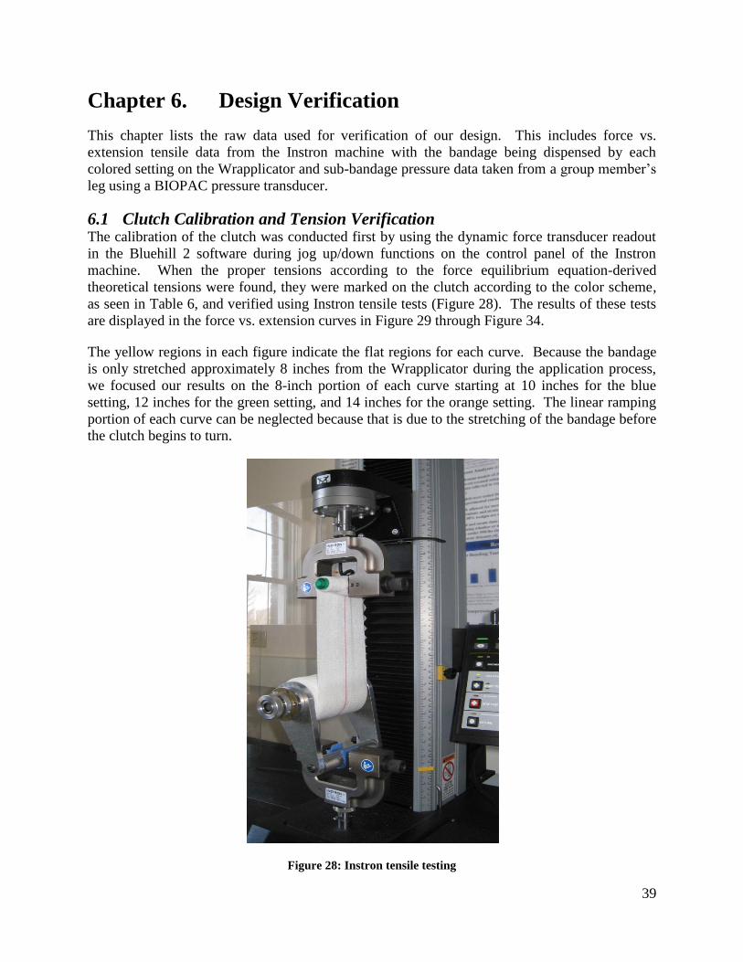
39
Chapter 6. Design Verification
This chapter lists the raw data used for verification of our design. This includes force vs.
extension tensile data from the Instron machine with the bandage being dispensed by each
colored setting on the Wrapplicator and sub-bandage pressure data taken from a group member’s
leg using a BIOPAC pressure transducer.
6.1 Clutch Calibration and Tension Verification The calibration of the clutch was conducted first by using the dynamic force transducer readout
in the Bluehill 2 software during jog up/down functions on the control panel of the Instron
machine. When the proper tensions according to the force equilibrium equation-derived
theoretical tensions were found, they were marked on the clutch according to the color scheme,
as seen in Table 6, and verified using Instron tensile tests (Figure 28). The results of these tests
are displayed in the force vs. extension curves in Figure 29 through Figure 34.
The yellow regions in each figure indicate the flat regions for each curve. Because the bandage
is only stretched approximately 8 inches from the Wrapplicator during the application process,
we focused our results on the 8-inch portion of each curve starting at 10 inches for the blue
setting, 12 inches for the green setting, and 14 inches for the orange setting. The linear ramping
portion of each curve can be neglected because that is due to the stretching of the bandage before
the clutch begins to turn.
Figure 28: Instron tensile testing

40
Figure 29: Force vs. extension curve for blue ankle setting
Figure 30: Force vs. extension curve for green ankle setting
0
0.5
1
1.5
2
0 5 10 15 20 25
Ten
sile
Fo
rce
(lb
f)
Extension (in)
Force vs. extension for blue ankle setting
Test 1
Test 2
Test 3
0
0.5
1
1.5
2
2.5
3
0 5 10 15 20 25
Ten
sile
Fo
rce
(lb
f)
Extension (in)
Force vs. extension for green ankle setting
Test 1
Test 2
Test 3

41
Figure 31: Force vs. extension curve for orange ankle setting
0
0.5
1
1.5
2
2.5
3
3.5
0 5 10 15 20 25
Ten
sile
Fo
rce
(lb
f)
Extension (in)
Force vs. extension for orange ankle setting
Test 1
Test 2
Test 3
0
0.5
1
1.5
2
2.5
3
3.5
0 5 10 15 20 25
Ten
sile
Fo
rce
(lb
f)
Extension (in)
Force vs. extension for orange ankle setting
Test 1
Test 2
Test 3
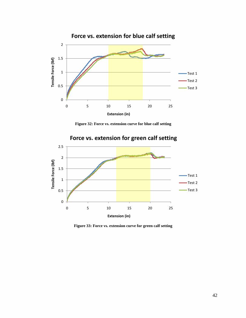
42
Figure 32: Force vs. extension curve for blue calf setting
Figure 33: Force vs. extension curve for green calf setting
0
0.5
1
1.5
2
0 5 10 15 20 25
Ten
sile
Fo
rce
(lb
f)
Extension (in)
Force vs. extension for blue calf setting
Test 1
Test 2
Test 3
0
0.5
1
1.5
2
2.5
0 5 10 15 20 25
Ten
sile
Fo
rce
(lb
f)
Extension (in)
Force vs. extension for green calf setting
Test 1
Test 2
Test 3

43
Figure 34: Force vs. extension curve for orange calf setting
6.2 Pressure Verification To verify that our theoretically derived pressure values were in fact valid, we utilized a pressure
transducer to find sub-bandage pressure of a leg after it was wrapped with the Wrapplicator. A
BIOPAC pressure transducer (TSD104A) was calibrated using hydrostatic pressure of water by
submerging the pressure pad (RX110) in a graduated cylinder of water. The calibration data for
the BIOPAC is shown below in Figure 35.
Figure 35: Water calibration of the pressure transducer via submersion of the pressure pad
Calibration data acquired from these results are listed below.
Depth that pressure pad was submerged in a graduated cylinder: 222 mmH2O
Change in voltage from normal atmospheric pressure to submersion: 0.372 volts
0
0.5
1
1.5
2
2.5
3
3.5
0 5 10 15 20 25
Ten
sile
Fo
rce
(lb
f)
Extension (in)
Force vs. extension for orange calf setting
Test 1
Test 2
Test 3
00.05
0.10.15
0.20.25
0.30.35
0.40.45
0.5
0 20 40 60 80 100
Vo
lts
Time (s)
Water calibration via submersion
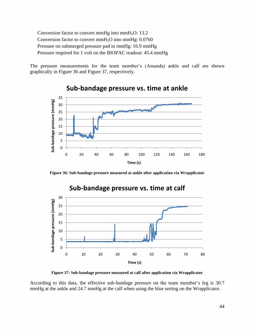
44
Conversion factor to convert mmHg into mmH2O: 13.2
Conversion factor to convert mmH2O into mmHg: 0.0760
Pressure on submerged pressure pad in mmHg: 16.9 mmHg
Pressure required for 1 volt on the BIOPAC readout: 45.4 mmHg
The pressure measurements for the team member’s (Amanda) ankle and calf are shown
graphically in Figure 36 and Figure 37, respectively.
Figure 36: Sub-bandage pressure measured at ankle after application via Wrapplicator
Figure 37: Sub-bandage pressure measured at calf after application via Wrapplicator
According to this data, the effective sub-bandage pressure on the team member’s leg is 30.7
mmHg at the ankle and 24.7 mmHg at the calf when using the blue setting on the Wrapplicator.
0
5
10
15
20
25
30
35
0 20 40 60 80 100 120 140 160 180
Sub
-ban
dag
e p
ress
ure
(m
mH
g)
Time (s)
Sub-bandage pressure vs. time at ankle
0
5
10
15
20
25
30
0 10 20 30 40 50 60 70 80
Sub
-ban
dag
e p
ress
ure
(m
mH
g)
Time (s)
Sub-bandage pressure vs. time at calf
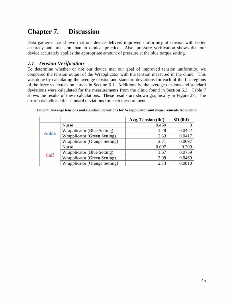
45
Chapter 7. Discussion
Data gathered has shown that our device delivers improved uniformity of tension with better
accuracy and precision than in clinical practice. Also, pressure verification shows that our
device accurately applies the appropriate amount of pressure at the blue torque setting.
7.1 Tension Verification To determine whether or not our device met our goal of improved tension uniformity, we
compared the tension output of the Wrapplicator with the tension measured in the clinic. This
was done by calculating the average tension and standard deviations for each of the flat regions
of the force vs. extension curves in Section 6.1. Additionally, the average tensions and standard
deviations were calculated for the measurements from the clinic found in Section 5.3. Table 7
shows the results of these calculations. These results are shown graphically in Figure 38. The
error bars indicate the standard deviations for each measurement.
Table 7: Average tensions and standard deviations for Wrapplicator and measurements from clinic
Avg. Tension (lbf) SD (lbf)
Ankle
Nurse 0.450 0
Wrapplicator (Blue Setting) 1.48 0.0422
Wrapplicator (Green Setting) 2.33 0.0417
Wrapplicator (Orange Setting) 2.71 0.0697
Calf
Nurse 0.607 0.200
Wrapplicator (Blue Setting) 1.67 0.0759
Wrapplicator (Green Setting) 2.09 0.0469
Wrapplicator (Orange Setting) 2.73 0.0810

46
Figure 38: Comparing tension output of the Wrapplicator with tension measured in clinic
It is clear that the Wrapplicator provides more precise tension at the calf than the nurse did in the
clinic because the standard deviations (error bars) of the calf tension measurements for the
Wrapplicator (±0.0810 maximum) are significantly smaller than that for the nurse (±0.200 lbf).
However, the Wrapplicator actually provided less precise tension at the ankle compared to the
nurse because the nurse applied identical tension at the ankle during each application, as seen in
Figure 18. It is possible that our measurements in the clinic were not precise enough, which
would explain why we measured the same tension at the ankle for each application.
7.2 Pressure Verification The preliminary data from the clinic showed variation in tension from patient to patient, and also
as the nurse applied the bandage up the leg. Furthermore, it was found theoretically that the
tension at which she was applying the bandages was far lower than what was required to apply
20-30 mmHg. The nurse was applying a maximum of 0.83 lbf of tensile force to the bandage,
and at some points during wrapping, less than half of this force. Force equilibrium equations
show that she was applying a maximum of approximately 6.7 mmHg at the calf and a pressure of
approximately 5.50 mmHg at the ankle. These calculations, previously explained in the final
design section, are shown below.
𝑃𝐶𝑎𝑙𝑓 𝑀𝑎𝑥 =𝑇∗4𝜋
𝑐∗𝑤=
.83 𝑙𝑏𝑓 ∗4∗𝜋
20 𝑖𝑛∗4 𝑖𝑛= 6.74 mmHg
𝑃𝐴𝑛𝑘𝑙𝑒 =𝑇∗4𝜋
𝑐∗𝑤=
.44 𝑙𝑏𝑓 ∗4∗𝜋
13 𝑖𝑛∗4 𝑖𝑛= 5.50 mmHg
Equation 5: Pressure applied by the nurse at the clinic
This means that the nurse was applying the bandage with a theoretical minimum of 66.3% error
and a theoretical maximum of 81.7% error. The calculations used to determine these values are
shown below.
0
0.5
1
1.5
2
2.5
3
Nurse Wrapplicator (Blue Setting)
Wrapplicator (Green Setting)
Wrapplicator (Orange Setting)
Ten
sio
n (
lbf)
Ankle
Calf
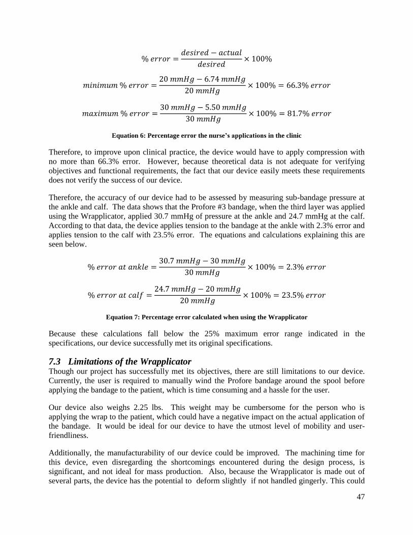
47
% 𝑒𝑟𝑟𝑜𝑟 =𝑑𝑒𝑠𝑖𝑟𝑒𝑑 − 𝑎𝑐𝑡𝑢𝑎𝑙
𝑑𝑒𝑠𝑖𝑟𝑒𝑑× 100%
𝑚𝑖𝑛𝑖𝑚𝑢𝑚 % 𝑒𝑟𝑟𝑜𝑟 =20 𝑚𝑚𝐻𝑔 − 6.74 𝑚𝑚𝐻𝑔
20 𝑚𝑚𝐻𝑔× 100% = 66.3% 𝑒𝑟𝑟𝑜𝑟
𝑚𝑎𝑥𝑖𝑚𝑢𝑚 % 𝑒𝑟𝑟𝑜𝑟 =30 𝑚𝑚𝐻𝑔 − 5.50 𝑚𝑚𝐻𝑔
30 𝑚𝑚𝐻𝑔× 100% = 81.7% 𝑒𝑟𝑟𝑜𝑟
Equation 6: Percentage error the nurse’s applications in the clinic
Therefore, to improve upon clinical practice, the device would have to apply compression with
no more than 66.3% error. However, because theoretical data is not adequate for verifying
objectives and functional requirements, the fact that our device easily meets these requirements
does not verify the success of our device.
Therefore, the accuracy of our device had to be assessed by measuring sub-bandage pressure at
the ankle and calf. The data shows that the Profore #3 bandage, when the third layer was applied
using the Wrapplicator, applied 30.7 mmHg of pressure at the ankle and 24.7 mmHg at the calf.
According to that data, the device applies tension to the bandage at the ankle with 2.3% error and
applies tension to the calf with 23.5% error. The equations and calculations explaining this are
seen below.
% 𝑒𝑟𝑟𝑜𝑟 𝑎𝑡 𝑎𝑛𝑘𝑙𝑒 =30.7 𝑚𝑚𝐻𝑔 − 30 𝑚𝑚𝐻𝑔
30 𝑚𝑚𝐻𝑔× 100% = 2.3% 𝑒𝑟𝑟𝑜𝑟
% 𝑒𝑟𝑟𝑜𝑟 𝑎𝑡 𝑐𝑎𝑙𝑓 =24.7 𝑚𝑚𝐻𝑔 − 20 𝑚𝑚𝐻𝑔
20 𝑚𝑚𝐻𝑔× 100% = 23.5% 𝑒𝑟𝑟𝑜𝑟
Equation 7: Percentage error calculated when using the Wrapplicator
Because these calculations fall below the 25% maximum error range indicated in the
specifications, our device successfully met its original specifications.
7.3 Limitations of the Wrapplicator Though our project has successfully met its objectives, there are still limitations to our device.
Currently, the user is required to manually wind the Profore bandage around the spool before
applying the bandage to the patient, which is time consuming and a hassle for the user.
Our device also weighs 2.25 lbs. This weight may be cumbersome for the person who is
applying the wrap to the patient, which could have a negative impact on the actual application of
the bandage. It would be ideal for our device to have the utmost level of mobility and user-
friendliness.
Additionally, the manufacturability of our device could be improved. The machining time for
this device, even disregarding the shortcomings encountered during the design process, is
significant, and not ideal for mass production. Also, because the Wrapplicator is made out of
several parts, the device has the potential to deform slightly if not handled gingerly. This could

48
have a negative impact on the amount of pressure applied to the leg of a patient if the device is
not readjusted for optimal performance.
Due to time constraints, we were not able to clinically validate our device because obtaining
approval from both the WPI and UMass Institutional Review Boards is a long process requiring
several months’ wait. However, we would like to arrange for a non-trained caretaker to use the
Wrapplicator to apply compression bandages to actual patients suffering from lower leg edema.
This would greatly corroborate the validity of our device.
7.4 Economic Impact As previously mentioned, it was found that about 12.5% of patients with ulcers took early
retirement because the reoccurrence of the ulcers prevented their continuation at work. Another
study found that chronic venous insufficiency (CVI) is the 14th
most-frequently quoted disease
for temporary work absenteeism and the 32nd
most frequent cause of permanent disability and
public financial assistance (Ruckley, 1997). With the annual estimated cost of treating the
sequelae associated with CVI exceeding $1 billion dollars, it can be said that CVI has a negative
economic impact on society.
Our device would look to improve these negative effects, thus having a positive economic
impact. Because the Wrapplicator can be used at home, this would hopefully improve patient
compliance. We found that the Profore wraps slouch during the week and patients simply
remove them due to the discomfort they caused. Because the patient would need to wait until
their next clinic appointment to have their leg re-wrapped, this would impede the healing of
venous ulcers and the alleviation of the patient’s edema (G. Fudem, Personal Correspondence,
September 5, 2008). Now, because the Wrapplicator allows the patient or caretaker to apply the
bandage whenever they deem necessary, this would hopefully require them to make fewer visits
to the clinic, saving valuable time and resources.
7.5 Environmental Impact The Wrapplicator would have minimal effect on the environment. One positive aspect of the
device, with respect to the environment, is that it is reusable. Thus, after using the Wrapplicator
to apply the bandage, it would not be thrown away, but rather it could be reused in subsequent
applications of the bandage. The Wrapplicator is adjustable to different leg sizes, and therefore
even if a patient’s edema decreases, they would only need to own one device, decreasing the
waste that would result from needing to purchase multiple devices.
The materials used in our device also have no negative bearing on the environment. The housing
of our device is made out of aluminum, which is a recyclable material. Additionally, the
operation of our device, unlike many other devices, does not rely on electrical power, which can
be harmful to the environment.
7.6 Societal Influence The ramifications of CVI have a large effect on our society, as nearly 25 million people in the
United States alone suffer from CVI (White, 2005). Because CVI drastically lowers the quality
of life for patients suffering from this disorder, this negatively affects the overall wellbeing of
society. The Wrapplicator aims to improve the quality of life for CVI patients by decreasing
clinic dependence. With the Wrapplicator, patients would be able to lead more independent

49
lives. Because such a large percentage of the population suffers from this disorder, if they had
increased independence, a drastic elevation of the quality of life for a major portion for the
population could be seen.
7.7 Political Ramifications We believe that our product has the potential to have an influence on the global market. The
Wrapplicator can be utilized in a number of worldwide markets – ranging from burn victims to
pregnant women. Another global use for our device is for wounded soldiers, who frequently use
compression therapy to treat wounds and severe swelling. Though our device could very well be
used on a global scale, it is not likely to have any negative political ramifications.
7.8 Ethical Concerns The Wrapplicator does not raise any ethical concerns, as it does not have the potential to
adversely affect anyone. Our device only improves upon current clinical practices, and there
exist few ethical issues, if any, associated with these practices. Compression therapy only seeks
to improve the quality of life for the patient and alleviate the sequelae associated with a very
debilitating health issue.
7.9 Health and Safety Issues The biggest asset of the Wrapplicator is its ability to improve the quality of life for the patients
who utilize it. It aims to improve the overall health and well being for the individual. Though
compression therapy does not cure CVI, it works by lessening the impacts of the disease. This
device should never negatively impact the health or safety of the patient.
7.10 Manufacturability The manufacturing of our device could easily be reproduced. As previously mentioned, the
device is composed of only three main constituents, the machining of which does not require
very advanced techniques. The parts are not small and intricate, as those of many other medical
devices are. The only machines required to manufacture our final device are a lathe, a CNC, an
arbor press, and a horizontal band saw.
7.11 Sustainability As the manufacturing of the Wrapplicator does not require high energy consuming machinery,
the carbon footprint left by the production of the device would be insignificant. The operation of
our device, as previously mentioned, does not require electrical power. Much emphasis has been
put on a products being environmentally sustainable, and our device satisfies this objective.

50
Chapter 8. Conclusions and Recommendations
8.1 Conclusions As outlined previously, chronic venous insufficiency is a very debilitating heath issue with many
sequelae such as varicose veins, lower leg edema, and ulcers (White, 2005). Through the use of
compression therapy, clinicians strive to minimize these debilitating effects. However, new
problems arise with compression therapy including loosening and slouching of the garment,
pressure sores, and the inability of the patient to bathe during the week. Our final design, the
Wrapplicator, improved on these shortcomings by allowing a patient or caretaker to reapply a
garment at home, as opposed to visiting the clinic multiple times a week.
The Wrapplicator met all of our objectives. The compression garment system can be applied at
home by the patient or caretaker, maintains constant tension in the bandage as it is applied to a
patient’s leg, and is reusable. The constant tension in the wrap was achieved by the use of the
torque-limiting clutch fastened to the spool. As the leg is wrapped, a pressure gradient is created
on the leg due to the increase in leg radius. This gradient is ideal for treating the sequelae
associated with CVI, particularly edema, allowing the fluid to be forced back up the leg and
decreasing swelling.
The device was comprised of three main constituents: the housing, the spool, and the torque-
limiting clutch. The housing of the device was built from two machined aluminum side plates,
an aluminum cylindrical handle, and two bolts that fastened the narrow end of each side plate to
each end of the handle. A plastic bearing was press-fitted into one of the aluminum side plates at
the wide end, while an anchoring device for the rotational motion of the torque-limiting clutch
was press-fitted into the wide end of the opposite side plate. The spool was built from a section
of PVC pipe with an aluminum end cap press-fitted into each end to create a hollow cylinder.
On the end of the spool adjacent to the face plate with the bearing, a shoulder bolt ran through
the bearing and fastened into the threaded end cap. On the other end of the spool, a dowel pin
was press-fitted into the end cap and ran through the anchoring device, extending out far enough
to also run through the torque-limiting clutch. A strip of Velcro hooks was adhered to the
circumferential surface of the spool to secure the bandage during use. Finally, the torque-limiting
clutch fastened onto the side of the housing, with set screws to hold it onto the dowel pin
extending from the spool and to hold it against the anchoring device. This clutch was calibrated
using a color scheme that allows it to be adjustable to different leg sizes and also to be adjustable
during application. This is necessary to address the change in tension that would otherwise be
detrimental due to the spool’s effective change in radius as the bandage is applied.
The device was verified using an Instron machine and a BIOPAC pressure transducer. The
Instron machine allowed us to see if constant tension was, in fact, being applied. Verification on
the Instron machine also allowed us to calibrate the torque limiting clutch, which aided us in
forming the development of the color system. This color system allowed the device to be
adjustable to different leg circumferences while maintaining a 20-30 mmHg pressure gradient up
the patient’s leg. To verify the theoretically derived pressure values of 20-30 mmHg were
actually accomplished by our device, we tested the pressure gradient with a BIOPAC pressure
pad for one of the leg ranges. Our results revealed that 20-30 mmHg was achieved on the leg
51
with no more than 25% error when all four layers of the Profore™ Multi-layer Compression
Bandage System were applied.
8.2 Future Recommendations Although the Wrapplicator does meet all of our objectives and functions, looking ahead, we
believe a few modifications could improve the efficacy of our device. These suggestions include
developing a way to ease loading of the bandage onto the device, constructing the device out of a
lightweight material, improving manufacturability, and further testing the device in the clinic.
Due to time and budget constraints, we were unable to implement these design ideas; however,
we hope that our clients will be able to utilize these proposed recommendations in order to
improve upon our design.
Currently, the bandage must be manually wound around the spool of the Wrapplicator. This is
not only time consuming, but also allows for error to occur. For example, while one person may
wrap it tightly around the spool, another person might wrap it loosely. This can affect the
tension the bandage as it unwinds from the spool, resulting in undesirable tension variations. An
easier way to load the wrap onto the Wrapplicator would be to include another device that can
attach to one of the side plates to automatically wind the bandage around the spool.
The Wrapplicator is made of three separate components: aluminum housing, a spool made out of
PVC with aluminum end caps, and a torque-limiting clutch. The current weight of our device is
2.25 pounds. We feel that we could further reduce the weight of our device by manufacturing it
as a single piece of plastic material. This would significantly reduce the weight of the
Wrapplicator, making it easier for the patient or caretaker to maneuver. In addition, this would
improve manufacturability because injection molding techniques are cheaper, faster, and more
precise than machining.
Finally, due to time constraints and the need for approval from both the WPI and UMass
Institutional Review Boards, our team was unable to test our device on patients in the clinic. We
believe that validation of the Wrapplicator by testing it on actual patients is necessary. This will
ensure that our color system on the torque-limiting clutch provides the correct tension, and
consequently, the correct pressure gradient, for varying leg sizes.

52
References
Agu, O., Baker, D., & Seifalian, A. M. (2004). Effect of graduated compression stockings on
limb oxygenation and venous function during exercise in patients with venous
insufficiency. Journal of Vascular Surgery, 12, 69-76.
Bamigboye, A. A., & Hofmeyr, G. J. (2006). Interventions for leg edema and varicosities in
pregnancy: What evidence? , 129(1), 3-8.
Benigni, J., Sadoun, S., Allaert, F. (2003). Efficacy of Class 1 elastic compression stockings in
the early stages of chronic venous disease. International Angiolgy, 24 (3), 224-238.
Berliner, E., Ozbilgin, B., & Zarin, D. (2003). A systematic review of pneumatic compression
for treatment of chronic venous insufficiency and venous ulcers. Journal of Vascular
Surgery, 37, 539-544
Buchtemann, A. S., Stein, A., Volkert, B., & al., e. (1999). The effects of compression therapy
on venous hemodynamics in pregnant women. British Journal of Obstetrics and
Gynaecology, 106, 563-569.
Choucair, M., & Phillips, T. J. (1998). Compression therapy. Dermatol Surg, 24(1), 141-148.
Heniford, B. T., Senler, S. O., Olsofka, J. M., & al., e. (1998). May-Thurner syndrome:
management by endovascular surgical techniques. Annals of Vascular Surgery, 22, 482-
486.
Horner, J., Fernandes, J., Fernandes, E., & Nicolaides, A. N. (1980). Value of graduated
compression stockings in deep venous insufficiency. Br Med J, 280(6217), 820-821.
Ibeguna, V., Delis, K. T., Nicolaides, A. N., & al., e. (2003). Effect of elastic compression
stockings on venous hemodynamics during walking. Journal of Vascular Surgery, 37,
420-425.
Jorgensen, P., Thoup, J., Fischer, A., Holst-Christensen, J., Flamsholt, R. (2005). Heparin with
and without graded compression stockings in the prevention of thromboembolic
complications of major abdominal surgery: A randomized trial. British Journal of
Surgery, 72 (7), 579-581.
Kolari, P., Pekanmaki, K. (1987). Effects of intermittent compression treatment on skin
perfusion and oxygenation in lower legs with venous ulcers. Vasa, 16, 312-317
Lacroix, P., Aboyans, V., Preux, P., Houles, M., Laskar, M. (2003) Epidemiology of venous
insufficiency in an occupational population. International angiology, 22, 172-176.
Nicolaides, A. N. (2000). Investigation of Chronic Venous Insufficiency : A Consensus
Statement. Circulation, 102(20), e126-163.

53
O’Meara, S., Cullum, N., Nelson, E. (2008). Compression for Venous Leg Ulcers. The
Cochrane Collaboration. 2: 1-124.
Prandoni, P., Lensing, A., Prins, M. (2005). Below knee elastic compression stockings reduced
development of post-thrombotic syndrome in proximal deep venous thrombosis.
Evidenced-Based Medicine, 10: 22-28.
Ruckley, C. (1997). Socioeconomic Impact of Chronic Venous Insufficiency and Leg Ulcers.
Angiology, 1, 67-69
Spence, R., Cahall, E. (1996). Inelastic versus elastic leg compression in chronic venous
insufficiency: A comparison of limb size and venous hemodynamics. Journal of
Vascular Surgery, 44, 783-787.
Valencia, I., Falabella, A., Kirsner, R., Eaglestein, W. (2001). Journal of the American
Academy of Dermatology, 44, 401-421.
White, J. V., Katz, M. L., Cisek, P., & Kreithen, J. (1996). Venous outflow of the leg: Anatomy
and physiology of the plantar venous plexus. Journal of Vascular Surgery, 24, 819-824.
White, J. V., & Ryjewski, C. (2005). Chronic Venous Insufficiency. Perspectives in Vascular
Surgery and Endovascular Therapy, 17(4), 319-327.

54
Appendix A. Patent Review
Inflatable compression garments
U.S. Patent #7,135,007
Compression garments and related methods
This patent describes a basic inflatable compression garment. This design employs the
use of a tubular body, with an inner and outer layer, which is fitted for different body
segments, such as arms and legs. Inflatable channels extend throughout the length of this
tubular body to provide compression. Also, there is a series of straps that encircle the
outer layer of the tubular body. These can be tightened or loosened accordingly to
provide adequate pressure variations or to better conform to the body segment being
compressed. This patent is useful because the compression garment for this project needs
to be easy to put on, which can be attained through the use of straps, and must provide
constant compression.
U.S. Patent #5,435,009
Inflatable compression garment
This patent describes a boot for lower leg compression, and employs the use of an
inflatable tongue for cushioning under the sole of the foot, and one inflatable chamber
that encompasses the rest of the lower leg and foot. A zipper along the front of the boot
allows for easy insertion of the foot and lower leg. Although this design employs the use
of a zipper and inflatable tongue for cushioning, both ideas that can be used to solve the
problem of preventing shear stress along the skin, but it seems to be bulky and is
probably not conducive to everyday wear.
U.S. Patent #4,029,087
Extremity compression device
This patent describes an extremity compression device which is an elongated pressure
sleeve that uses pressurized fluid to apply compression to a limb. The device has
separate fluid pressure chambers arranged longitudinally along the sleeve. The means of
filling the chambers applies greater pressure in the lower chambers than the upper
chambers to create a pressure gradient. The chambers can be filled and emptied either
sequentially or simultaneously. The device also has the ability to apply compression and
decompression cycles.
Strap-based compression garments
U.S. Patent #US2007/0179421
MODULAR COMPRESSION DEVICE AND METHOD OF ASSEMBLY
This patent describes a fitted garment comprised of a series of bands of compressible or
non-compressible material. These bands are fastened together by a flexible spine that
runs along the length of the limb to which the garment is being applied. The bands are
then wrapped around the limb to apply compression. These garments are fitted in such a
way that the user can measure his or her limb according to the requirements of a

55
document that can then be mailed to the manufacturer. The manufacturer then sends the
fitted garment to the patient.
U.S. Patent #5,918,602
Therapeutic compression garment
This patent describes a therapeutic compression device, made with a flexible, foldable,
lightweight, Velcro-type loop fabric. There is a central region with pairs of extending
bands that encompass the body part. The central region can be reinforced with one or
more flexible rods to prevent wrinkling, collapsing, or slippage. The invention also
includes a separate ankle-foot wrap to apply compression to the foot and ankle. Finally,
the invention also includes a conjoined device with both the leg portion and the ankle
foot wrap.
U.S. Patent #6,315,745
Compression garment for selective application for treatment of lymphedema
This patent describes a compression garment that is custom made for each patient and
hermetically sealed to provide graded air pressure along the leg, arm, or mid-section of a
patient. It is layered to provide comfort and also allows different sections of the garment
to have different air pressures so that the proper amounts of pressure is applied at
different points in the leg, arm, or mid-section. This device would be able to be applied
by the patient through the use of a wrap-around system with Velcro and/or hooks and
would be made out of a flexible material in order to provide comfort and mobility to the
patient.
Miscellaneous compression garments
U.S. Patent #6,613,007
Multilayer compression stocking system and method
This patent describes a multilayered compression stocking system comprised of a
plurality of layers, including an underlayer and at least one overlayer. The underlayer has
one or more alignment markings. Each alignment marking is positioned at a different
location on the respective layer, and each alignment marking on a layer corresponds to a
different one of the alignment marking on each other layer. Accurate pressure is
achieved when the markings on the layers align. By adjusting the location of each
marking, pressures can be alternated at discrete locations. The background of this patent
discusses the drawbacks of multi-layer stockings used on the market. This patent aims to
make a compression stocking system that is easier to correctly apply and more
economical and efficient to manufacture.
U.S. Patent #6,062,946
Post-pregnancy compression garment
This patent describes a post-pregnancy compression garment, which has features that
could be applied to a compression garment for chronic venous insufficiency. While this
compression garment is worn around the abdomen of a woman (post-pregnancy), it is
also relevant in that it offers insight into the type of material and weave pattern used to
achieve a state of effective compression on a variety of abdomen sizes. Maximum
compression is provided to the waist section of the garment, while there is minimum

56
compression in the remaining portion. If the elected design employs graded pressure, this
patent demonstrates the technique in which materials are used to apply this pressure
gradient.
Compression stocking applicators
U.S. Patent #5,826,761
Anti-embolism stocking aid
This patent describes a device that provides an easier means of application for a sock or
compression stocking on the leg of a patient. The wearer may have trouble putting these
garments on due to the pressure of the stocking or the age of the wearer, and this
invention offers another option for putting them on. The device is in a U-shape and is the
length of an average sized leg, and has a much larger width, with two openings at both
ends for the insertion of the leg. The sock or stocking is placed over the end of the device
and the wearer places their leg into the open hole of the device. This reduces shear stress
caused on the leg and allows the wearer to put the stocking on without pain or struggle.
The problem with this device, however, is that the person must be strong enough to
stretch the stocking over the device before putting it on. This may cause a problem with
elderly or weaker individuals if the stocking pressure is too high. In the case of chronic
venous insufficiency, 25-35 mmHg is a typical pressure range and therefore would be too
difficult to stretch without the aid of a technician.
U.S. Patent #6,536,636
Support hose applicator
This patent describes a compressions stocking applicator made of an elastic tubular
material with an expandable support ring with rotatable segments and a mandrel with
elongated sidewalls. Basically, the compressions stocking is first stretched over the
mandrel, and the support ring is placed over the hose and mandrel. Next, the hose is
rolled onto the support ring as the support ring is rolled along the mandrel. As the
support ring is rolled along the limb of the patient, the hose is applied to the limb.
Additionally, the support ring can expand and contract.

57
Appendix B. Pairwise Comparison Charts (Initial)
Chart 8: Main objectives (as weighed by team)
Easy to
use/apply
Patient
friendly
Efficacy Safe Total+1
Easy to
use/apply
x 1 0 0 2
Patient friendly 0 x 0 0 1
Efficacy 1 1 x 0 3
Safe 1 1 0 x 3
Chart 9: Overall weights for main objectives
Objective Weight (Team) Weight (Dr. Fudem) Weight (Average)
Easy to use/apply .222 .125 .174
Patient friendly .111 .187 .149
Efficacy .333 .187 .26
Safe .333 .5 .417

58
Chart 10: Easy to use/apply sub-objectives (as weighed by team)
Easy to use/apply Disposable
/Readily-
Washable
Must be able to be
worn for up to one
week
Can be put on by
patient or caretaker
(non-medical
professional)
Total+1
Disposable/Readily-
Washable
x .5 0 1.5
Must be able to be worn for
up to one week
.5 x 0 1.5
Can be put on by patient or
caretaker (non-medical
professional)
1 1 x 3
Chart 11: Overall weights for Easy to Use/Apply sub-objectives
Objective Weight
(Team)
Weight (Dr.
Fudem)
Weight
(Average)
Disposable/Readily-Washable .25 .333 .292
Must be able to be worn for up to one
week
.25 .167 .209
Can be put on by patient or caretaker
(non-medical professional)
.5 .5 0.5
Chart 12: Patient Friendly sub-objectives (as weighed by team)
Patient friendly Must be
lightweight
Must be
durable
Must be
breathable
Must be able to fit
variety of leg sizes
Total+1
Must be lightweight x .5 0 0 1.5
Must be durable .5 x 1 0 2.5
Must be breathable 1 0 x 1 3
Must be able to fit
variety of leg sizes
1 1 0 x 3

59
Chart 13: Overall weights for Patient Friendly sub-objective
Chart 14: Efficacy sub-objectives (as weighed by team)
Efficacy Must be able to be coated with
medication or permit the
application of medicated
dressing
Must be able to maintain
consistent and
reproducible (equal or
graded) pressure
Total+1
Must be able to be
coated with
medication or
permit the
application of
medicated dressing
x 0 1
Must be able to
maintain consistent
and reproducible
(equal or graded)
pressure
1 x 2
Chart 15: Overall weights for Efficacy sub-objective
Objective Weight (Team) Weight (Dr. Fudem) Weight
(Average)
Must be able to be coated with
medication or permit the application
of medicated dressing
.333 .333 .333
Must be able to maintain consistent
and reproducible (equal or graded)
pressure
.666 .666 .666
Objective Weight (Team) Weight (Dr.
Fudem)
Weight (Average)
Must be lightweight .15 .2 .175
Must be durable .25 .2 .225
Must be breathable .3 .4 .35
Must be able to fit variety of leg sizes .3 .2 .25

60
Chart 16: Safe sub-objectives (as weighed by team)
Safe Must not disturb
wounds
Must not wrinkle and cause hot
spots
Total+
1
Must not disturb
wounds
x 0 1
Must not wrinkle and
cause "hot spots"
1 x 2
Chart 17: Overall weights for Safe sub-objectives
Objective Weight (Team) Weight (Dr. Fudem) Weight (Average)
Must not disturb wounds .333 .333 .333
Must not wrinkle and cause "hot
spots"
.666 .666 .666

61
Appendix C. Weighted Objectives Tree (Initial)
Figure 39: Weighted objectives tree for design objectives and sub-objectives
Objectives
Easy to use/apply
.174
Disposable/Readily-Washable
.051
Worn for up to one week
.036
Put on by patient or caretaker
.087
Patient Friendly
.149
Lightweight
.026
Durable
.034
Breathable
.052
Fits variety of leg sizes
.037
Effective in Treating CVI
.26
Maintains consistent and reproducible pressure
.173
Coated with medication or permit the application of
medicated dressing
.087
Safe
.417
Should not wrinkle and cause "hot spots"
.278
Should not disturb wounds
.139

62
Appendix D. Numerical Evaluation Matrix (Initial)
Table 18: Numerical evaluation matrix for conceptual design ideas
Design
Constraints/Objectives
Weight
(%)
Multi-
chambered
inflatable
c.g.
Inflatable
c.g. with
hydrostatic
pressure
Shrink-
wrap c.g.
(heat
activated)
Spray-on
c.g.
Woven
superelas
tic
garment
Innovation
to current
wraps
C: Must not induce shear
stress
C: Must not cost more than $10/day to manufacture
C: Must be easily
manufactured
C: Material needs to be readily available
C: Cannot cause adverse
side effects
O:Easy to use/apply 17 0.5 x 17%
8.5%
0.4 x 17%
6.8%
0.7 x 17%
11.9%
0.75 x 17%
12.75%
0.8 x 17%
13.6%
0.7 x 17%
11.9%
O:Patient Friendly 15 0.4 x 15%
6%
0.3 x 15%
4.5%
0.6 x 15%
9%
0.4 x 15%
6%
0.7 x 15%
10.5%
0.7 x 15%
10.5%
O:Effective in treating CVI 26 0.6 x 26%
15.6%
0.6 x 26%
15.6%
0.7 x 26%
18.2%
0.4 x 26%
10.4%
0.8 x 26%
20.8%
0.6 x 26%
15.6%
O:Safe 42 0.5 x 42%
21%
0.5 x 42%
21%
0.6 x 42%
25.2%
0.6 x 42%
25.2%
0.7 x 42%
29.4%
0.5 x 42%
21%
TOTALS 100 51% 48% 64% 54% 74% 59%

63
Appendix E. Spring Specifications
Table 19: Specifications of constant force spring from McMaster-Carr (Part Number: 9293K48)
Type Constant-Force Springs
Material Stainless Steel
Stainless Steel Type Type 301 Stainless Steel
Cycle Life 4,000
Thickness .007"
Length 26"
Width .50"
Outside Diameter When Wound .75"
Outside Diameter Tolerance When
Wound
± 10%
Inside Diameter When Wound .59"
Inside Diameter Tolerance When Wound ± 10%
Load 1.62 lbs.
End Hole Diameter .131"
Number of End Holes 1

64
Appendix F. SolidWorks Drawings

65

66

67

68

69
Appendix G. Budget
Vendor Contents Cost
Peterson Steel Aluminum Cylinder $15.75
Biopac Systems, Inc. Pressure Pad (RX110) $65.00
Pressure Pad (RX110) $66.00
Walgreens Compression Stockings $20.00
McMaster-Carr Bearings – Plastic x 4 (6455K27) $21.32
Bearings – Metal x 2 (6383K41) $13.50
Constant-force spring (9293K48) $9.60
Shoulder bolt (91259A705) $2.16
Polyclutch Torque-limiting clutch (PAO32-8H) $105.99
Lowe’s Polyethylene tubing $1.54
Adhesive $3.28
Steel rod $2.33
Spray adhesive $3.98
Target Ribbon $2.99
Pantyhose stocking $4.99
Smallparts.com Nitinol wires $11.90
Total Cost $350.33